

Simeon Sim.LED 5000 SC, Sim.LED 7000 SC, Sim.LED 5000 MC, Sim.LED 7000 MC, Sim.LED 450 SC Installation manual
...Page 1
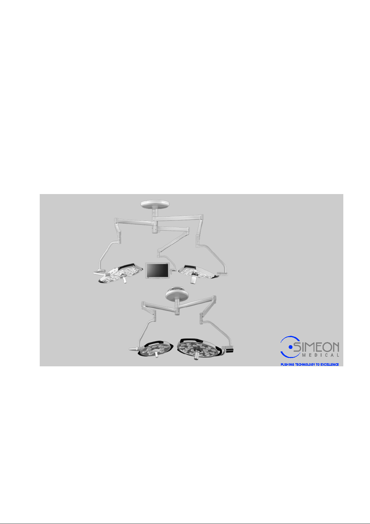
Installation Instructions
before starting any work!
Surgical LightingSim.LED
450/500/700/5000/7000 SC/MC
Doc. ID: 100-0010179-EN – V. 1.7
CO 003-01163
Please read these instruction s
Page 2

S.I.M.E.O.N. Medical GmbH & Co. KG 2016
S.I.M.E.O.N. Medical GmbH & Co. KG
In Grubenäcker 18
D-78532 Tuttlingen
Telephone: +49 (0) 7461 90068-0
Fax: +49 (0) 7461 90068-901
E-mail: [email protected]
Internet: www.simeonmedical.com
Technical Service
S.I.M.E.O.N. Medical GmbH & Co. KG
Telephone: +49 (0) 7461 90068-888
E-mail: [email protected]
©
V. 1.7 2
Page 3

Installation Instructions Surgical LightingSim.LED 450/500/700/5000/7000 SC/MC
Table of Contents
1 General .............................................................................................. 7
1.1 Information on theseInstallation Instructions ........................... 7
1.2 Explanation of symbols .......................................................... 10
1.3 Spare parts ............................................................................. 11
1.4 Warranty provisions ............................................................... 11
1.5 Technical Service ................................................................... 11
1.6 Intended use .......................................................................... 13
1.7 Incoming inspections.............................................................. 13
1.8 Duties of the operator............................................................. 14
1.9 Personnel requirements/qualifications ................................... 16
1.10 Dismantling and disposal ....................................................... 16
2 Transportation, packaging and storage ....................................... 17
2.1 Transportation inspection ....................................................... 17
2.2 Packaging .............................................................................. 17
2.3 Transport ................................................................................ 18
3 Design and function ....................................................................... 20
3.1 Variants .................................................................................. 20
3.1.1 Light head ............................................................... 20
3.1.2 Camera ................................................................... 20
3.1.3 Ceiling variant ......................................................... 21
3.1.4 Ceiling variant with Sim.F LEX ................................ 22
3.1.5 Mobile variants (illustration similar) ........................ 23
3.1.6 Sim.LED 450 wall variant (only available as
version with simple cardanic) ................................. 24
4 Mounting ......................................................................................... 25
4.1 Ceiling variant ........................................................................ 25
4.1.1 Mounting the ceiling anchor plate ........................... 26
4.1.2 Mounting the suspended ceiling fitting ................... 26
4.1.3 Mounting the round ceiling tube or Sim.FLEX ........ 29
4.1.4 Fit Sim.FLEX adapter to round ceiling tube ............ 32
4.1.5 Mounting the round central axis ............................. 33
4.1.6 Mount Sim.FLEX extension arms ........................... 36
4.1.7 Mounting adapter on spring arm / spring arm on
extension arm ......................................................... 38
4.1.8 Mounting adapter on spring arm / mounting
spring arm on Sim.FLEX extension arm ................. 42
4.1.9 Mounting spring arm adapter (optional delivery
variant) .................................................................... 45
4.1.10 Mounting the light heads onto the spring arm ........ 48
4.1.11 Mounting and connecting the power supply unit
for surgical lights to the ceiling tube ....................... 49
V. 1.7 3
Page 4

Installation Instructions Surgical LightingSim.LED 450/500/700/5000/7000 SC/MC
Table of Contents
4.1.12 Installing the Sim.INTERFACE ............................... 53
4.1.13 Connecting the Sim.INTERFACE ........................... 55
4.1.14 Mounting the wall controls ...................................... 56
4.1.15 Mounting canopy to ceiling tube ............................. 58
4.1.16 Mount rotating canopy to Sim.Flex extension arm
and normal central axis .......................................... 59
4.1.17 Mounting the Sim.FLEX ceiling tube cover ............ 60
4.2 Connecting the Sim.CAM HD Touch on separate extension
arm ......................................................................................... 62
4.2.1 Mount Sim.CAM HD TOUCH camera mount onto
spring arm ............................................................... 62
4.2.2 Mounting the Sim.CAM HD TOUCH onto the
camera mount ......................................................... 63
4.2.3 Connecting the Sim.CAM HD TOUCH ................... 64
4.3 Mounting the Sim.CAM HD (Sim.LED 5000/7000 only) ........ 67
4.3.1 Sim.CAM HD terminal board .................................. 69
4.3.2 Example: Sim.CAM HD wiring diagram .................. 70
4.3.3 Connecting the Sim.STREAM ................................ 71
4.4 Mounting the Sim.SCREEN monitor suspension ................... 72
4.4.1 Overview ................................................................. 72
4.4.2 Mounting the extension arm ................................... 73
4.4.3 Mounting adapter to AC3000/OSP spring arm ....... 73
4.4.4 Mounting the AC3000/OSP spring arm .................. 76
4.4.5 Mounting the Sim.SCREEN monitor mount to the
AC3000/OSP spring arm ........................................ 77
4.4.6 Sim.SCREEN monitor mount: Positioning the
lateral stop pieces
4.4.7 Connect monitor suspension cabling ..................... 80
4.4.8 Mount GTP8 and GTP14 ........................................ 86
4.5 Mounting the mobile variants (illustration similar) .................. 87
4.5.1 Installation of mobile variants report ....................... 87
4.5.2 Mount spring arm on stand (Module variant only) .. 91
4.5.3 Adjust spring force on spring arm (mobile variant
only) ........................................................................ 94
4.5.4 Mounting covers on mobile variant ......................... 95
4.5.5 Establishing power supply for mobile variant ......... 96
4.6 Mounting the Sim.LED 450 wall variant ................................. 97
4.6.1 Mounting the wall bearing ....................................... 98
4.6.2 Electrical connection ............................................. 100
4.6.3 Mount extension arm and wall bearing, correct
locking ring disassembly and mounting ................ 101
4.6.4 Mounting the spring arm to the extension arm
Sim.LED 450 ......................................................... 104
................................................... 78
V. 1.7 4
Page 5

Installation Instructions Surgical LightingSim.LED 450/500/700/5000/7000 SC/MC
Table of Contents
4.6.5 Mount light head on LC spring arm (wall and
ceiling variant only) ............................................... 106
5 Adjustments .................................................................................. 107
5.1 Mount the spring arm shells on the spring arm (ceiling
variant only) .......................................................................... 107
5.1.1 Mounting the cover sheets ................................... 108
5.2 Setting the spring force: Ceiling variant ............................... 109
5.3 Synchronisation of colour temperature and Sim.Biance (for
Sim.Interface, for MC lights only) ......................................... 110
5.4 Setting the height limit: LC spring arm (ceiling and wall
variant only) .......................................................................... 111
5.5 Setting the braking power .................................................... 112
6 Confirmation of static bearing capacity ..................................... 113
7 Installation report ......................................................................... 115
8 Technical data .............................................................................. 119
8.1 Technical data Sim.LED 5000 SC ....................................... 119
8.2 Technical data Sim.LED 7000 SC ....................................... 120
8.3 Technical data Sim.LED 5000 MC ....................................... 121
8.4 Technical data Sim.LED 7000 MC ....................................... 124
8.1 Technical data Sim.LED 450 SC ......................................... 125
8.2 Technical data Sim.LED 500 SC ......................................... 126
8.3 Technical data Sim.LED 700 SC ......................................... 127
8.4 Technical data Sim.LED 450 MC ......................................... 129
8.5 Technical data Sim.LED 500 MC ......................................... 130
8.6 Technical data Sim.LED 700 MC ......................................... 131
8.7 Dimension sheets ................................................................. 134
8.7.1 Sim.LED 5000/7000 ceiling variant ...................... 134
8.7.2 Sim.LED 5000 mobile variant ............................... 135
8.7.3 Sim.LED 7000 mobile variant ............................... 136
8.7.4 Sim.LED 450 ceiling variant ................................. 137
8.7.5 Sim.LED 500 ceiling variant ................................. 138
8.7.6 Sim.LED 700 ceiling variant ................................. 139
8.7.7 Sim.LED 450 wall variant ..................................... 140
8.7.8 Sim.LED 450 mobile variant ................................. 141
8.7.9 Sim.LED 500 mobile variant ................................. 142
8.7.10 Sim.LED 700 mobile variant ................................. 143
8.7.11 Wall controls, single .............................................. 144
8.7.12 Wall control, double .............................................. 144
8.7.13 Wall control, triple ................................................. 145
9 Approved combinations/lengths ................................................ 146
9.1 Approved Sim.FLEX combinations ...................................... 146
V. 1.7 5
Page 6

Installation Instructions Surgical LightingSim.LED 450/500/700/5000/7000 SC/MC
Table of Contents
9.2 Approved combinations for standard carrier arms in
conjunction with OndaSpace spring arms ........................... 147
9.3 Approved length for Sim.LED 450 wall mounting ................ 147
V. 1.7 6
Page 7
Installation Instructions Surgical LightingSim.LED 450/500/700/5000/7000 SC/MC
1 General
1.1 Information on theseInstallation Instructions
Any changes to this medical device are fundamentally not allowed.
These Installation Instr uctio ns instructions enable the safe and
efficient assembly and installation of the Sim.LED
450/500/700/5000/7000 SC/MC. The Installation
InstructionsService Manual must be stored so that they are
accessible to the lighting manufacturer's service personnel or
personnel authorised by the manufacturer. The
must be followed in ascending order.
As a rule, medical devices may only be installed, operated,
controlled and maintained by persons who possess the required
training, knowledge and experie nce.
General
assembly sequence
Safety information
Installation, maintenance and repairs may only be conducted by
authorised, qualified personnel as a minimum requirement.
Authorisation is granted upon completion of a training course and
receipt of a certificate from the manufacturer. The qualified
personnel in question must have carefully read these Installation
Instructions and understood their contents before starting any work.
The basic requirement for a safe work process is the adherence to
all safety and handling instructions in these Installation Instructions
in ascending order. Furthermore, local regulations for working with
medical equipment in sterile rooms such as operating theatres,
apply.
The illustrations in this manual are provided for basic
understanding and could deviate from the actual design. Service
work is described in a separate Service Manual. Operation of the
lights and accessories is described in the respective Instructions for
Use.
Safety information in these Installation Instructions is identified by
symbols.
Risk of death or severe bodily injury!
Non-observance could possibly result in death or severe bodily
injury!
Risk of injury!
Non-observance could result in bodily injury!
Risk of material damages: Non-observance of the instructions
may result in damage to or destruction of the product or other
objects, as well as loss of data or loss of working hours.
V. 1.7 7
Page 8

Installation Instructions Surgical LightingSim.LED 450/500/700/5000/7000 SC/MC
General
Symbols
Cable colours in circuit diagrams
Indicates handling ins truc ti ons .
Indicates a status or an automatic sequence as a result of
a handling step
“Reference title”, page 24
is a cross-reference to a chapter in this document.
Instructions for Use of this lighting
is a cross-reference to a separate document.
Abbreviation Cable colour (en) Cable colour (ger)
BK Black Schwarz
BU Blue Blau
BN Brown Braun
GN Green Grün
GNYE Green-Yellow Grün-gelb
OG Orange Orange
RD Red Rot
YE Yellow Gelb
Copyright protection
TR Transparent Transparent
These Installation Instr uctio ns are copyright-protected.
Transferring these Installation Instructions to a third party,
reproducing them in any type or form – even if only partial – and
using and/or disseminating their contents are prohibited without
written authorisation from the manufacturer.
Infringements will be liable to claims for damages.
We reserve the right to assert further claims.
V. 1.7 8
Page 9

Installation Instructions Surgical LightingSim.LED 450/500/700/5000/7000 SC/MC
General
Limitation of liability
All specifications and instructions in these Installation Instr uc tions
have been compiled under consideration of applicable norms and
standards, the current state of the art and our many years of
knowledge and experience.
We will accept no liability. The warranty and guarantee will become
inapplicable in the event of damages resulti ng from:
− Non-observance of these Installat ion Instr uct ions
− Non-observance of the Service Manual
− Non-adherence to the designated use / specific function
− Failure to document and observe the defined maintenance
plan and safety-relate d inspections
− Start-up currents and overvoltage
− Use by non-qualified personnel
− Modifications conducted independently
− Technical modifications
− Use of a defective or improperly repaired unit
− Use of unauthorised spare parts or accessories
The actual scope of delivery may deviate from the explanations or
illustrations provided in this manual in the case of special designs,
the use of additional order options, or due to the most recent
technical changes.
V. 1.7 9
Page 10
Installation Instructions Surgical LightingSim.LED 450/500/700/5000/7000 SC/MC
General
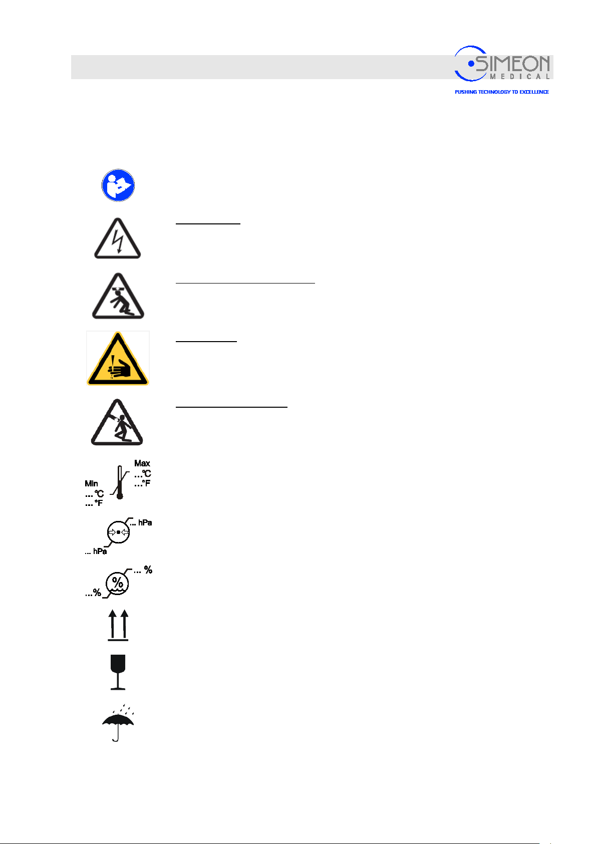
1.2 Explanation of symbols
The following symbols can be found on the type plate and/or packaging. The symbols must always be
observed.
Adhere to the Instructions for Use
Electric shock: Warns of an electric shock which can cause severe injury or even
death.
Collapse of bearer arm system: Warns of the bearing arm system suddenly
collapsing due to faulty mounting.
Cutting injury:
Warns of cuts. Wear protective gloves.
Spring arm snapping up: Warns of the spring arm snapping up suddenly when the
adaption or end device is disass em bled.
Specifications on minimum and maximum ambient temperature for storage and
transportation
Specifications on minimum and maximum air pressure for storage and
transportation.
Specifications on minimum and maximum air humidity for storage and
transportation
The arrows point towards the top side of the package. They must always point
upwards; otherwise, the contents could be damaged.
This symbol identifies packages that contain breakable or sensitive contents.
Handle the package carefully, do not allow it to drop and do not subject it to any
V. 1.7 10
blows.
Protect the package from wetness and keep dry.
Page 11
Installation Instructions Surgical LightingSim.LED 450/500/700/5000/7000 SC/MC
In addition, our personnel is always interested in hearing about new
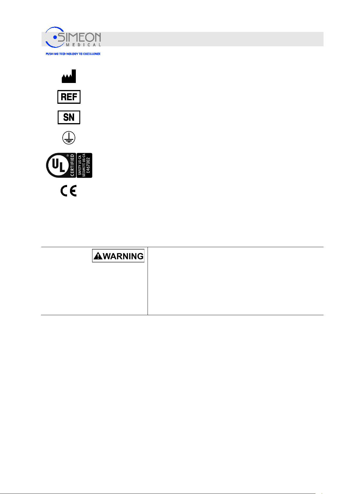
Date of manufacture and manufacturer's address
Article number
Serial number
Protective grounding (ground)
Medical Equipment – General Medical Equipment
ONLY COMPLIES WITH ANSI/AAMI ES60601-1 (2005), CAN/CSA-C22.2 No. 60601-1 (2008), IEC
60601-2-41:2009, UL 606011:2006, CAN/CSA-C22.2 No. 601.1 AND IEC 60601-2-41:2000
STANDARDS WITH RESPECT TO ELECTRICAL SHOCK, FIRE AND MECHANICAL HAZARDS
CE mark of conformity
General
1.3 Spare parts
1.4 Warranty provisions
Procure spare parts from your authorised dealer or directly from the
manufacturer. For the address, see page 2.
Risk of injury due to the use of incorr ect spare parts!
The use of incorrect or defective spare parts may place
personnel and patients at risk as well as cause damage,
malfunctions, or a total breakdown of the unit.
Only use original manufacturer spare parts or manufacturer-
approved spare parts.
If uncertain, always contact the manufacturer.
The warranty provisions are contained in the manufacturer's
General Business Terms and Conditions.
The manufacturer's warranty is voided if unauthorised spare parts
and devices are used. Authorised devices can be found in the valid
Instructions for Use. Authorised spare parts can be found in the
valid Spare Parts Price List.
1.5 Technical Service
V. 1.7 11
Our Technical Service is available to provide technical information.
For contact information, see page 2.
Page 12

Installation Instructions Surgical LightingSim.LED 450/500/700/5000/7000 SC/MC
information and experiences that may arise from use of the product
General
and that may be valuable for the improvement of our products.
Claims of any type due to damages caused by misuse, alteration or
modification of the light are excluded.
V. 1.7 12
Page 13
Installation Instructions Surgical LightingSim.LED 450/500/700/5000/7000 SC/MC
1.6 Intended use
General
The concept of intended use also includes adherence to all
specifications in these Installation Instructions and the separate
Instructions for Use. Any use that exceeds the intended use, and
any other kinds of uses, are considered to be incorrect uses.
Danger due to incorrect use!
Incorrect use of the unit may lead to dangerous situations. The
following are especially considered to be incorrect uses:
− Use of the unit in facilities that have not been built in
compliance with applicable s tandards and gu ide lines
regulating the construction of medical facilities.
− Use of the unit in explosion-prone areas.
− Use of a damaged unit.
Any type of claims against the manufacturer due to damages
caused by misuse, alteration or modification of the light are
excluded.
1.7 Incoming inspections
Inspect your delivery against the delivery slip for completeness and
integrity, immediately after receipt. The goods must be checked for
transport damages. The manufacturer or dealer must be notified of
any potential transport damages within 5 business days.
− Opening of the unit.
− Use of the unit by unqualified personnel.
− Use of the unit when objects are hanging from its extension
arm, spring arm or light head.
Risk of injury due to falling objects!
Parts may fall off of damaged goods.
Any goods which may be damaged may not be installed and
must be reported to the manufacturer immediately.
V. 1.7 13
Page 14

Installation Instructions Surgical LightingSim.LED 450/500/700/5000/7000 SC/MC
General
1.8 Duties of the operator
Responsibility to instruct
The operator must inform himself of all applicable accident
prevention and hygiene regulations, and must additionally conduct
a risk assessment at the site where the unit will operate in order to
identify any risks posed by the particular work conditions. The
regulations must be implemented in the form of instructions for
operation of the unit.
During the entire time that the unit is in use, the operator must
check whether the operating instructions that he prepared comply
with current technical regulations and revise them if necessary.
The operator must clearly establish and manage responsibilities in
the areas of installation, operation, troubleshooting, maintenance
and cleaning.
The operator must ensure that all employees who handle the unit
have read and understood the Instructions for Use.
Technical safety inspections
No liability in the event of noncompliance with time limits!
Translation
Furthermore, he must train personnel at regular intervals and
inform them of all dangers. He must also place safeguards so that
unauthorised persons do not use the unit.
The operator must ensure that the maintenance intervals and
technical safety inspections described in these Installation
Instructions are adhered to and documented.
The operator must ensure that only approved accessories and
accessories released by the manufacturer are used together with
the unit.
The operator must allow technical safety inspections to be
conducted annually.
Technical safety checks may only be conducted by the
manufacturer's personnel, or by authorised specialists who have
received written approval from the manufacturer.
The protocol prepared by the authorised specialist, detailing the
measurement procedures, measurement results, and other
evaluations, must be kept until the ligh tin g is disp os ed of
completely.
The manufacturer assumes no liability for personal injury or
material damages if technical safety inspections are not contracted
and conducted within the time limits provided.
In the case of translations into other languages, the German
version shall be binding.Instal lat ion Ins truc ti ons
V. 1.7 14
Page 15

Installation Instructions Surgical LightingSim.LED 450/500/700/5000/7000 SC/MC
General
Notification of accidents and
damages
Malfunctions or unit defects that lead to bodily injury must be
immediately notified to the authorities in charge and to the
manufacturer.
The authorities in charge may request that the operator submit the
incident being notified to a technica l safety evaluation by an
authorised expert, at its own expense, and that the evaluation be
submitted in writing to such authorities. The authorised expert will
be selected in consultation with the author it ies in char g e.
The technical safety evaluation will include determinations on:
− the cause of the incident
− the proper condition of the unit
− the risk situation following rectification of the fault
− the procurement of new knowledge as a result of the incident,
requiring revised or additional precautionary measures to
those already described
V. 1.7 15
Page 16
Installation Instructions Surgical LightingSim.LED 450/500/700/5000/7000 SC/MC
General
1.9 Personnel requirements/qualifications
As a rule, the medical devices described in these Installation
Instructions may only be installed, operated, controlled and
maintained by persons who have been trained and authorised to do
so by S.I.M.E.O.N. Medical GmbH & Co. KG.
Risk of death due to faulty installation or faulty initial startup!
Errors during the installation or initial start-up may result in lifethreatening situations and cause considerable material damages.
For that reason, please note the following:
The installation and initial start-up may only be conducted by
the manufacturer's personnel or by persons authorised by
the manufacturer.
The manufacturer must also be involved when conducting
unit relocations at a later time.
Unauthorised installation and relocations are prohibited.
1.10 Dismantling and disposal
Disposal of the unit
Disposal of packaging
The unit must be dismantled and undergo environmentally friendly
disposal.
Dismantling may only be conducted by trained, qualified personnel.
Risk of death due to improper dismantli n g!
Errors during dismantling may result in life-threatening situat ions
and cause significant material damages.
Only allow trained, qualified personnel to conduct
The manufacturer must also be involved when conducting
unit relocations at a later time.
Unauthorised dismantling and relocations are prohibited.
The packaging must undergo environmentally friendly disposal.
The packaging may be returned to the manufacturer.
dismantling.
V. 1.7 16
Page 17
Installation Instructions Surgical LightingSim.LED 450/500/700/5000/7000 SC/MC
Transportation, packaging and storage
2 Transportation, packaging and storage
The installation and initial start-up should be exclusively conducted by the manufacturer's personnel or
by persons authorised by the manufacturer.
The case may be, however, that operators or the operator's maintenance personnel are entrusted with
the handling of packaged items during the course of installation and further use. In such a case, the
following instructions must be heeded!
Risk of material damages due to improper transportation!
Transported items may fall or topple over as a result of improper
transportation. This can result in costly material damages.
When unloading items during delivery, and in the case of in-house
transportation, it is important to proceed cautiously and to heed the
instructions on the packaging.
Use only the designated suspension points.
Do not remove packaging until immediately before assembly.
2.1 Transportation inspection
2.2 Packaging
Inspect the delivery immediately upon receipt for completeness and possible
transportation damages.
If any exterior transportation damages are discovered, proceed as follows:
Do not accept delivery or only accept it conditionally.
Write down the extent of damages on the transportation documents or on the
transportation company's delivery note.
Initiate a claim.
Submit a claim for every fault as soon as it is discovered. Claims for damages
can only be asserted within the claim period in effect.
The individual items have been packaged in accordance with the
expected transportation conditions. Only environmentally friendly
materials were used for the packaging.
The packaging should protect the individual components from
transportation damages, corrosion, or other damages, up until the
time of assembly. Therefore, do not destroy the packaging and
only remove it shortly before assembly. Dispose of packaging
materials in accordance with valid legal regulations and local
standards.
V. 1.7 17
Page 18

Installation Instructions Surgical LightingSim.LED 450/500/700/5000/7000 SC/MC
Transportation, packaging and storage
2.3 Transport
Transport all packaged items under the following conditions:
Do not store outdoors.
Store in a dry and dust-free environment.
Transport temperature: -10
Protect from sunlight.
Avoid any mechanical vibrations.
Ambient temperature: - 10°C to max. + 50°C
Relative air humidity: min. 10% max. 90 %
Risk of environmental damage due to improper disposal!
Packaging materials are valuable raw materials and can, in many cases, be
reused or be sensibly processed and recycled. The improper disposal of
packaging materials may result in danger to the environment.
Dispose of packaging materials in an environmentally friendly way.
Observe the applicable local disposal regulations. If needed, contract a
specialist company for such disposal.
°C to 50 °C
Air pressure min. 500 hPa max. 1060 hPa
When transporting parts for longer than three months, check the general condition of all parts
and their packaging regularly.
If required, recondition or replace the preservation measures.
V. 1.7 18
Page 19

2.4 Storage
Store the packaged items under the following conditions:
Do not store outdoors.
Store in a dry and dust-free environment.
Do not expose to any aggressive media.
Protect from sunlight.
Avoid any mechanical vibrations.
Installation Instructions Surgical LightingSim.LED 450/500/700/5000/7000 SC/MC
Transportation, packaging and storage
Storage temperature: -10
°C to max. 50 °C
Relative air humidity: min. 10% max. 90 %
Air pressure min. 500 hPa max. 1060 hPa
When storing parts for longer than three months, check the general condition of all parts and
their packaging regularly.
If required, recondition or replace the preservation measures.
Storage instructions that exceed the requirements mentioned
herein may be found on the packaged items. These must be
adhered to accordingly!
V. 1.7 19
Page 20
Installation Instructions Surgical LightingSim.LED 450/500/700/5000/7000 SC/MC
Design and function
3 Design and function
3.1 Variants
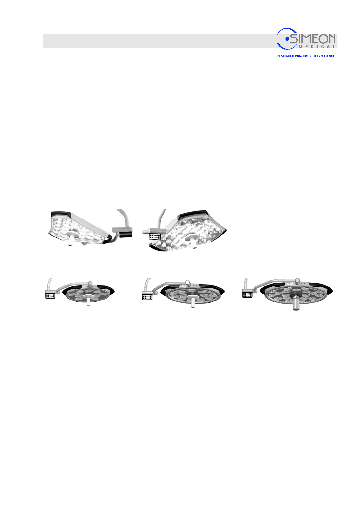
The different variants of the Surgical LightingSim .LED 450/ 500/ 700 /50 00/7000 SC/MC surgical lights are
exclusively intended for the illumination of treatment and surgical areas used in medicine. The mobility of the
light heads is guaranteed through a system consisting of extension arms, spring arms, a cardanic, and light
heads. The surgical lights and the camera, as an optional accessory, are operated through the control
panels on the light heads and on the wall. The light head is positioned using the unsterile handles and the
sterilisable handle.
The Surgical LightingSim.LED 450/500/700/5000/7000 SC/MC surgical light is available in different variants.
3.1.1 Light head
The various type designations generally denote light heads with different numbers and designs of Sim.PODs
(reflector/LED unit),
“Technical data“, page 119:
Sim.LED 5000 (SC)
24 reflectors
Sim.LED 450 (SC)
12 reflectors
Multi-colour lights (MC) allow you to select the factory-set colour temperatures on the control panel,
Instructions for Use Sim.LED 450/500/700 and Sim.LED5000/7000.
Sim.LED 7000 (SC)
32 reflectors
Sim.LED 500 (SC)
18 reflectors
Sim.LED 700 (MC, with
Sim.CAM)
24 reflectors
3.1.2 Camera
Lights with camera preparation can transmit/process the signals of a Sim.CAM SD or Sim.CAM HD TOUCH
accordingly, Instructions for Use Sim.LED 450/500/700 and Sim.LED 5000/7000.
V. 1.7 20
Page 21
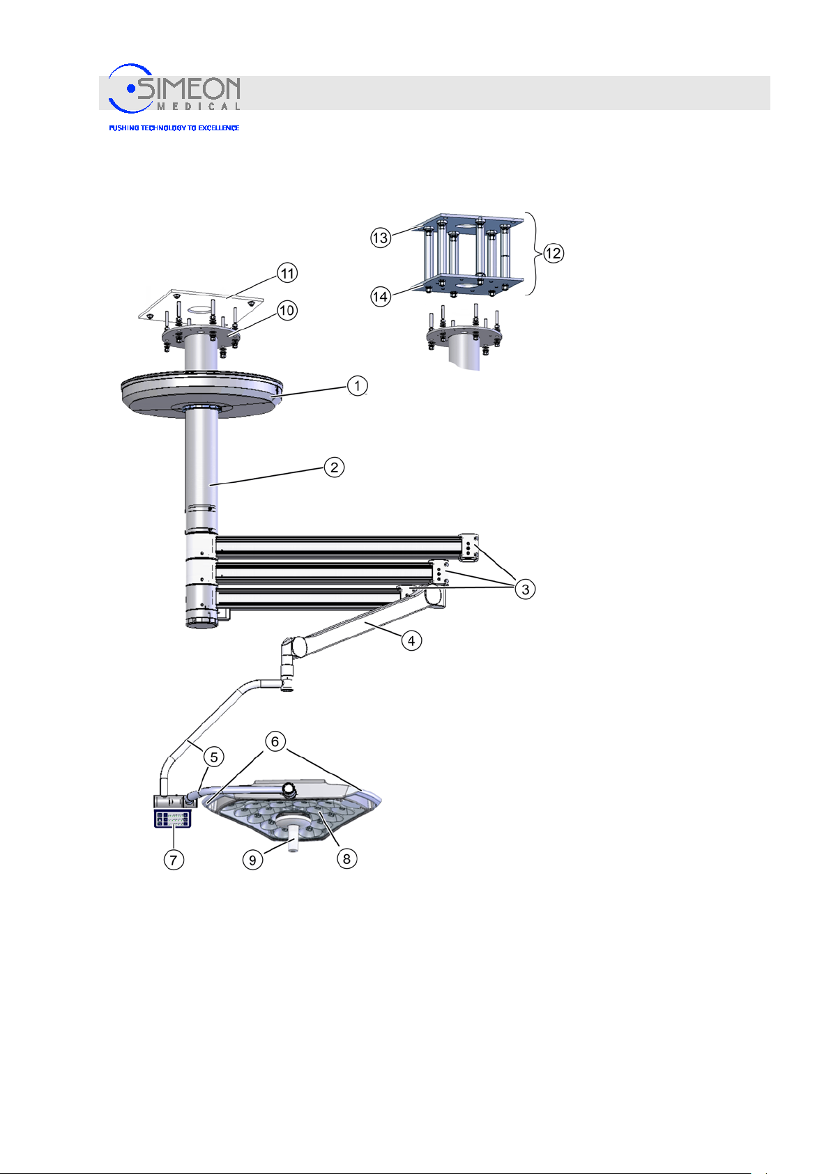
Installation Instructions Surgical LightingSim.LED 450/500/700/5000/7000 SC/MC
1
Canopy
8
Light head (here: Sim.LED 5000 MC)
2
Ceiling tube
9
Sterilisable handle / Sim.CAM
3
Extension arm (different variants)
10.
Ceiling tube flange
4
Spring arm
11
Ceiling anchor plate
5
Cardanic
12
Suspended ceiling fitting (if required)
6
Handles
13
Ceiling plate
7
Light controls
14
Carrier plate
3.1.3 Ceiling variant
Design and function
V. 1.7 21
Page 22
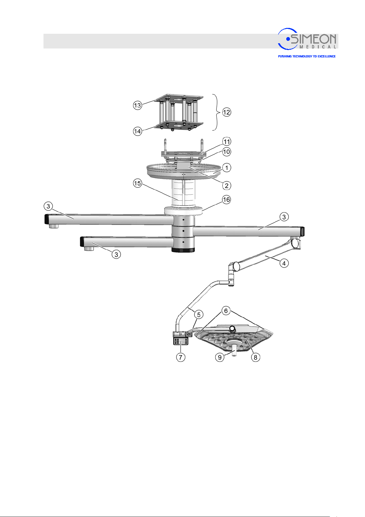
Installation Instructions Surgical LightingSim.LED 450/500/700/5000/7000 SC/MC
1
Sim.FLEX canopy
9
Sterilisable handle / Sim.CAM
2
Sim.FLEX ceiling tube
10.
Ceiling tube flange
3
Sim.FLEX extension arm
11
Ceiling anchor plate
4
Spring arm
12
Suspended ceiling fitting (if required)
5
Cardanic
13
Ceiling plate
6
Handles
14
Carrier plate
7
Light controls
15
Sim.FLEX ceiling tube cover
8
Light head (here: Sim.LED 5000 MC)
16
Sim.FLEX rotating canopy
Design and function
3.1.4 Ceiling variant with Sim.FLEX
V. 1.7 22
Page 23
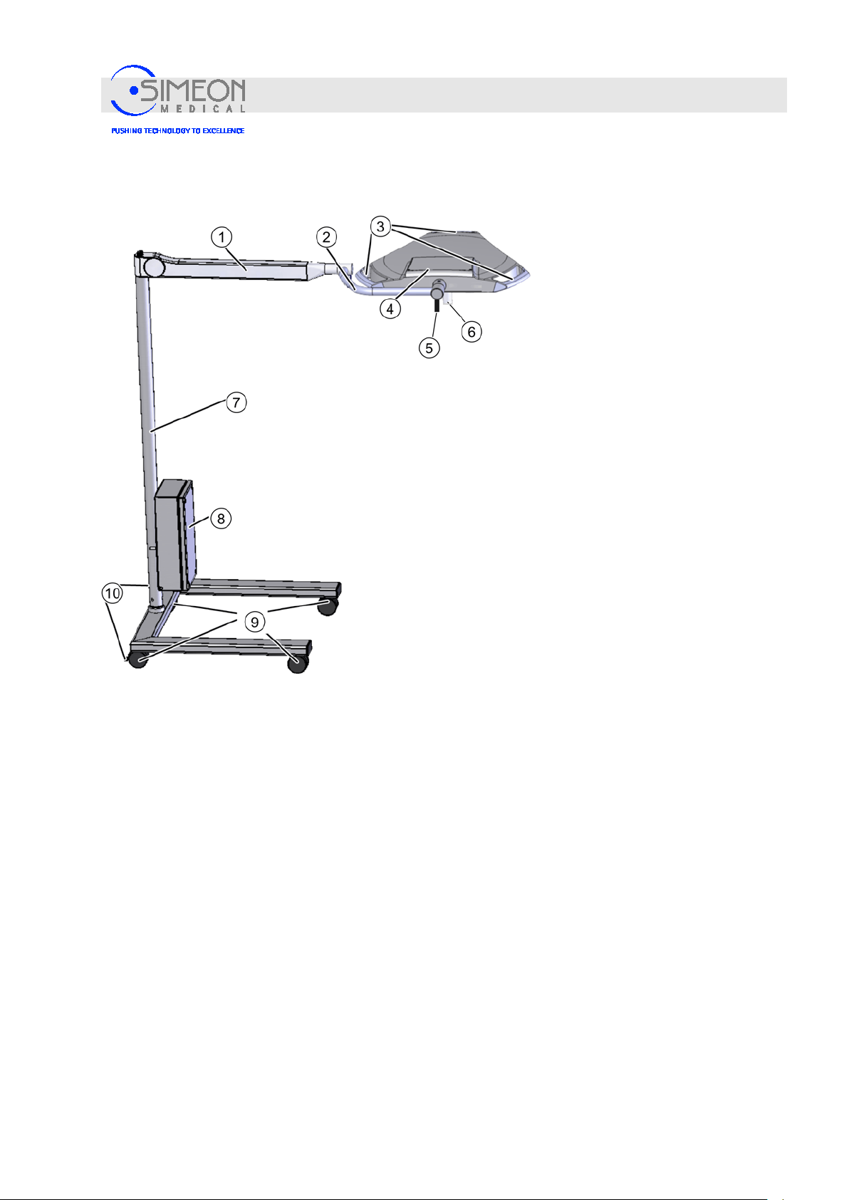
Installation Instructions Surgical LightingSim.LED 450/500/700/5000/7000 SC/MC
1
Spring arm, straight outlet (illustrat i on si mil ar)
6
Sterilisable handle
2
Cardanic
7
Mobile stand
3
Handles
8
Junction box
4
Light head (Example: Sim.LED 5000 MC)
9
Casters
5
Light controls
10.
Stop brakes
3.1.5 Mobile variants (illustration similar)
Design and function
V. 1.7 23
Page 24
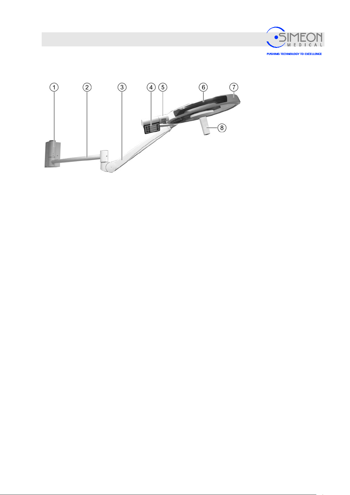
Installation Instructions Surgical LightingSim.LED 450/500/700/5000/7000 SC/MC
1
Wall bearing
5
Cardanic
2
Extension arm
6
Handles (non-sterile)
3
Spring arm, lateral outlet
7
Light head
4
Light controls (MC)
8
Sterilisable handle
Design and function
3.1.6 Sim.LED 450 wall variant (only available as version with simple cardanic)
V. 1.7 24
Page 25
Installation Instructions Surgical LightingSim.LED 450/500/700/5000/7000 SC/MC
4 Mounting
4.1 Ceiling variant
Mounting
Risk of injury from failing to follow thes e Installation
Instructions. Installations may only be carried out by trained
and authorised qualified personnel.
Consumption of alcohol or drugs prior to or during
installation are strictly prohibited. The safety, warning and
cautionary instructions must be followed!
Risk of death due to heavy objects!
Parts could fall down while the components are being mount ed.
This could cause severe or even fatal injuries.
Never attempt to lift heavy objects by yourself.
If available, use a hoisting platform or a lift.
Mount with at least 2 trained and authorised technicians!
Wear tight-fitting clothing.
Never wear rings, necklaces and other jewellery.
Cover long hair with hairnets.
Risk of death due to improper faste n ing of stud bolts! Risk
of injury due to reuse of stud bolts!
The collapse of the ceiling structure can result in a lifethreatening situation. Stud bolts are not suited for multiple uses.
Their reuse could thus imperil their bearing capacity and result in
injuries to personnel and patients, as well as material damages to
the unit.
The ceiling must be inspected and approved by a structural
engineer prior to installation.
Only use the stud bolts once
Adhere to the specified torque for the stud bolts.
Use only the stud bolts supplied.
V. 1.7 25
Page 26
Installation Instructions Surgical LightingSim.LED 450/500/700/5000/7000 SC/MC
Mounting
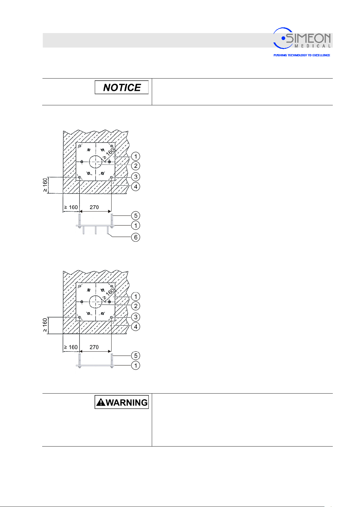
4.1.1 Mounting the ceiling anchor plate
Only mount the ceiling anchor plate on an absolutely horizontal
level surface (< ± 0.1°), there may be no offset areas on the
ceiling.
Have a structural engineer inspect and approve the ceiling,
“Confirmation of static bearing capacity“, page113.
The ceiling must be a flat surface, without any irregularities.
Observe the minimum distance to the wall (see illustration).
Drill and thoroughly blow out 4 holes (3) in the ceiling (4) for
the HSL3G M12 stud bolts (5), in accordance w ith the
attachment bracket manufacturer’s specifications
(www.hilti.de).
Mount stud bolts (5) accordance with the attachment bracket
manufacturer's specifications.
Using stud bolts (5), screw the ceiling anchor plate (1) to the
ceiling (4) and tighten each stud bolt with a torque of 60 Nm.
4.1.2 Mounting the suspended ceiling fitting
Mounting the ceiling plate
Have a structural engineer inspect and approve the ceiling,
“Confirmation of static bearing capacity“, page113.
The ceiling must be a flat surface, without any irregularities.
Observe the minimum distance to the wall (see illustration).
Drill and thoroughly blow out 4 holes (3) in the ceiling (4) for
the HSL3G M12 stud bolts ( 5), in accor danc e with the
attachment bracket manufacturer’s specifications
(www.hilti.de).
Mount stud bolts (5) accordance with the attachment bracket
manufacturer's specifications.
Using stud bolts (5), screw the ceiling plate (1) to the ceiling
(4) and tighten each stud bolt with a torque of 60 Nm.
Risk of death due to improper faste n ing of threaded rods!
If the threaded rods are not screwed in deeply enough into the
ceiling plate, the load-bearing capacity of the structure will not be
guaranteed and the load-bearing system could collapse!
Therefore, always use the entire thickness of the ceiling plate
when screwing in the threaded rods!
V. 1.7 26
Page 27
Installation Instructions Surgical LightingSim.LED 450/500/700/5000/7000 SC/MC
Mounting
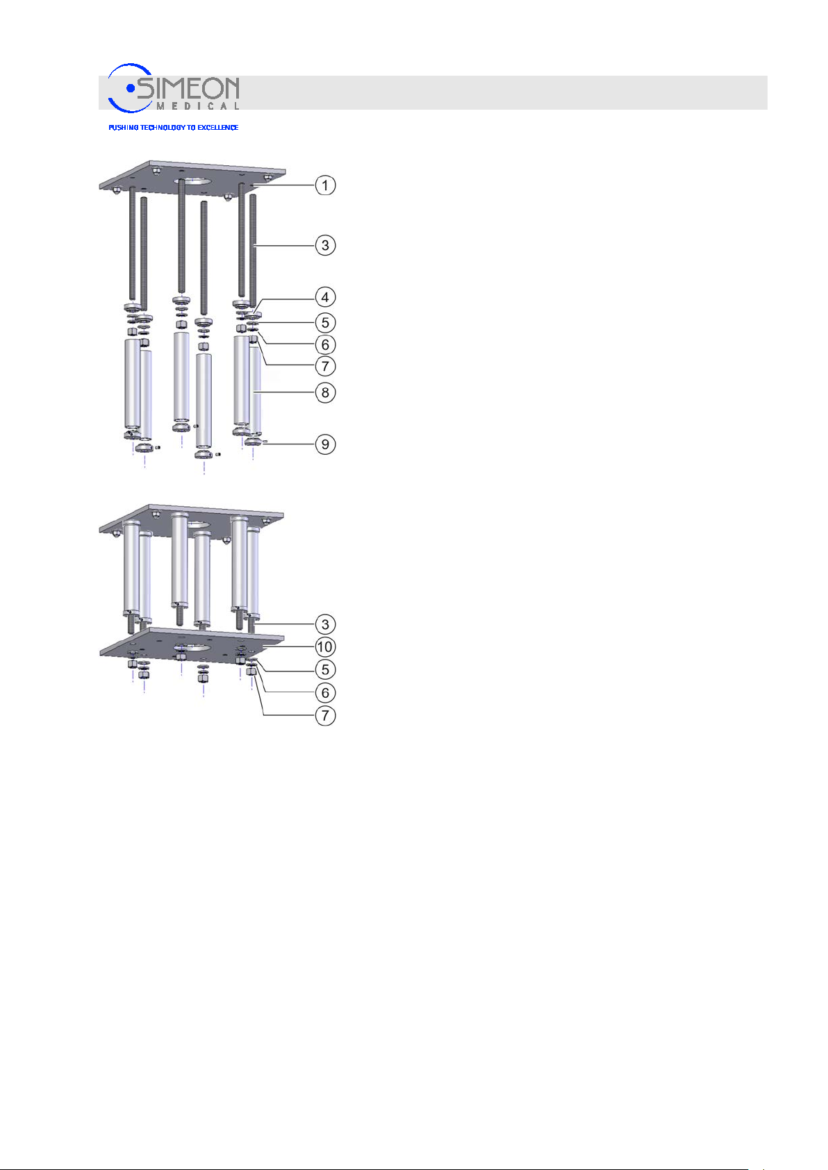
Mounting the threaded rods for the carrier plate
Screw in the threaded rods M16 (3) as far as possible into
the ceiling plate (1).
Slide the piping flange (4) without threa ded pi n, wash er M16
(5) and spring washer M16 (6) onto the threaded rod (3), and
fasten with a nut M16 (7).
Tighten the nut M16 (7) with 65 Nm.
Attach the spacer tube (8).
Attach the piping flange (9) and secure agains t t wist ing using
a threaded pin.
The spacer tube is thus secured against falling.
Mount the remaining threaded rods in the same manner.
Mounting the carrier plate
Slide the carrier plate (10) onto the six threaded rods M16
(3) and hold in place.
Secure the carrier plate with three nuts (7) to prevent it from
falling.
The carrier plate is thus secured against falling.
Slide one washer M16 (5) and one spring washer M16 (6)
onto each of the three free threaded rods M16 (3), and
secure with a nut M16 (7).
Loosen and remove the temporary nuts without washers.
Slide one washer M16 (5) and one spring washer M16 (6)
onto each of the three remaining threaded rods M16 (3), and
secure with a nut M16 (7).
Successively tighten all six nuts (7) with 65 Nm.
V. 1.7 27
Page 28
Installation Instructions Surgical LightingSim.LED 450/500/700/5000/7000 SC/MC
Mounting
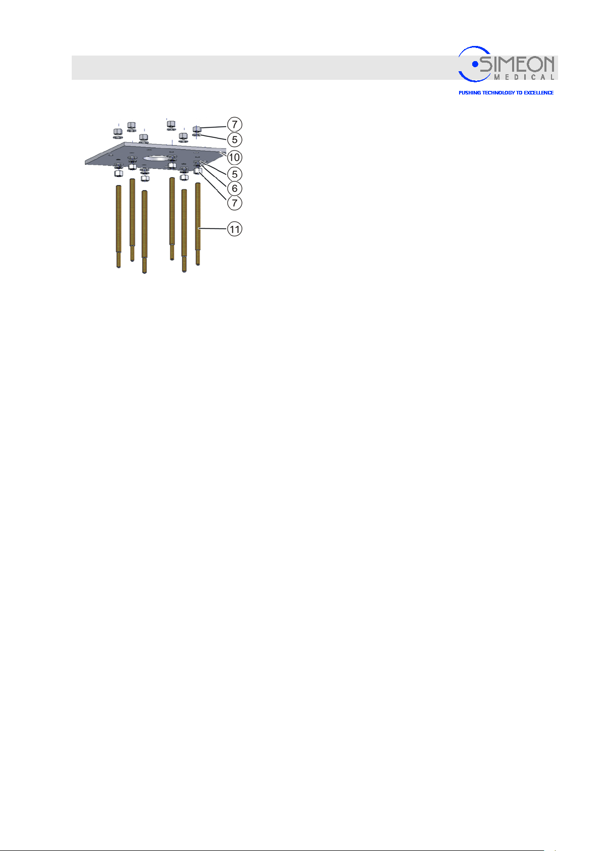
Mounting the threaded rods for the ceil ing tube
The ceiling tube flange is positioned approximately 200 mm
above the intermediate ceiling.
Screw the threaded rod M16 (11) through the carrier plate
(10) until the beginning of the smaller thread achieves the
desired height.
Apply a washer M16 (5) to the threaded rod on the top side
of the carrier plate and secure with a nut M16 (7).
Slide one washer M16 (5) and one spring washer M16 (6)
onto the threaded rod (11) on the bottom side of the carrier
plate (10), and secure with a nut M16 (7).
Mount the remaining threaded rods (11) in the same
manner.
Tighten the nuts M16 (7) on the bottom side of the carrier
plate (10) with 65 Nm; at the same time, tighten the
respective nuts M16 (7) on the top.
V. 1.7 28
Page 29
Installation Instructions Surgical LightingSim.LED 450/500/700/5000/7000 SC/MC
Mounting
4.1.3 Mounting the round ceiling tube or Sim.FLEX
The ceiling tube is now mounted onto the threaded rods M12 of the ceiling anchor plate. With an
intermediate ceiling construction, the ceiling tube is mounted onto the threaded rods M12 that were screwed
into the carrier plate.
Danger of injury from falling parts!
Since mounting the arms requires overhead work, injuries can be
caused by parts falling from above. This is especially the case if
not all of an extension arm's six mounting screws are correctly
tightened in sequence!
Mount the silicone retaining ring before the extension arms!
Before mounting the extension arms, the silicone retaining ring
that accommodates the ceiling tube cover must be correctly
mounted, “Mounting the ceiling tube for Sim.FLEX“, page 31.
This is no longer possible after mounting the extension
arms!
If a monitor mount is included in the lighting system, the central
axis for the corresponding extension arm is delivered together
with a stop piece. When mounting the ceiling tube, it is important
to ensure that the range of rotation of this extension arm is as
desired. To this end, the ceiling tube can be turned in steps of
60° before mounting. During mounting, the central axis allows
additional adjustments of the range of rotation of 120° each,
“Mounting the round central axis“, page 33.
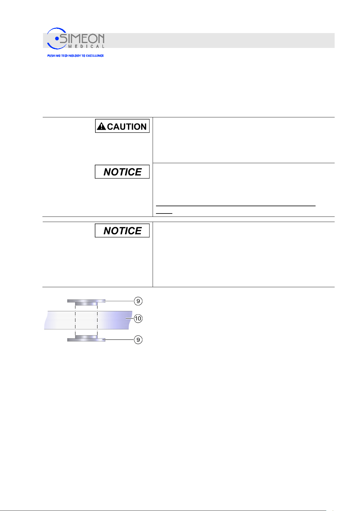
Mounting the threaded rods for the ceiling tube in insulated
form
The threaded rods of the ceiling tube are electrically insulated
from the ceiling tube (10) with the help of insulating washers (9).
To this end, the insulating washers (9) must be mounted as
demonstrated here: Their sleeves are inserted in the holes in the
ceiling tube.
V. 1.7 29
Page 30
Installation Instructions Surgical LightingSim.LED 450/500/700/5000/7000 SC/MC
Mounting
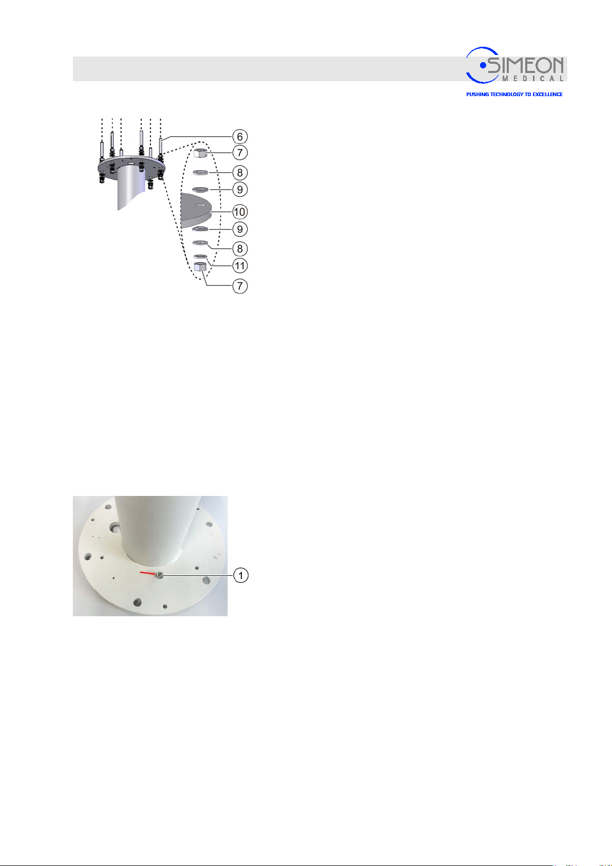
Mount round ceiling tube
Screw a nut (7) onto each of the six threaded rods M12 (6).
Align the nuts horizontally using a spirit level.
Insert a washer (8) and an insulating washer (9) with the
sleeve facing downwards onto each of the six threaded rods
M12 (6) and then secure together with the ceiling tube
against falling. Here, the sleeves of the insulating washers (9)
must slide from above into the holes in the ceiling tube flange
without diff ic ulty.
Temporarily secure every second threaded rod M12 (6) with
a nut M12 (7).
The ceiling tube (10) is thus secured against falling.
Apply one insulating washer (9) with the sleeve facing
upwards, one washer (8) and one spring was her (11) onto
each of the three free threaded rods, and secure with a nut
M12 (7). Here, the sleeves of the insulating washers must
slide upwards into the holes in the flange without difficulty.
Loosen and remove the temporary nuts without washers.
Apply one insulating washer (9) with the sleeve facing
upwards, one washer (8) and one spring washer (11) onto
each of the three freed threaded rods, and secure with a nut
M12 (7). Here, the sleeves of the insulating washers must
slide upwards into the flange's boreholes without difficulty.
Check the ceiling tube (10) with the spirit level and
realign if necessary. To do so, readjust the nuts M12 (7) as
needed.
Alternately tighten the nuts M12 (7) on the bottom side of the
ceiling tube (10) crosswise with 45 Nm; at the same time,
tighten the respective nuts M12 (7) on the top.
Connect the ceiling tube to the customer-supplied
equipotential bonding using the M6 cylinder screw (1)
that is supplied for this purpose. Here, use a cable with a
cross-section ≥ 6 mm². In addition, adhere to the
effective regulations for installation in the building (e.g.
VDE 0100-710).
V. 1.7 30
Page 31
Installation Instructions Surgical LightingSim.LED 450/500/700/5000/7000 SC/MC
Mounting
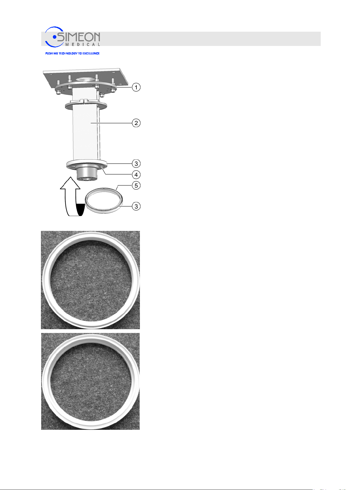
Mounting the ceiling tube for Sim.FLEX
Mount the Sim.FLEX system's ceiling tube flange (1) on the six
threaded rods in exactly the same way as described above for the
flange of the round ceiling tube Ø 125 mm.
Align the Sim.Flex extension arm vertically on mounting surface
using a spirit level.
Slide the silicone retaining ring (3) for the ceiling tube cover onto
the flange (4) of the ceiling tube (2) from below, ensuring that the
ceiling tube cover's groove (5) points upwards. This is no longer
possible after mounting the extension arms!
The ceiling tube is now ready to mount the Sim.FLEX extension
arms.
The silicone retaining ring (3) seen from above.
The silicone retaining ring (3) seen from below
V. 1.7 31
Page 32
Installation Instructions Surgical LightingSim.LED 450/500/700/5000/7000 SC/MC
Mounting
4.1.4 Fit Sim.FLEX adapter to round ceiling tube
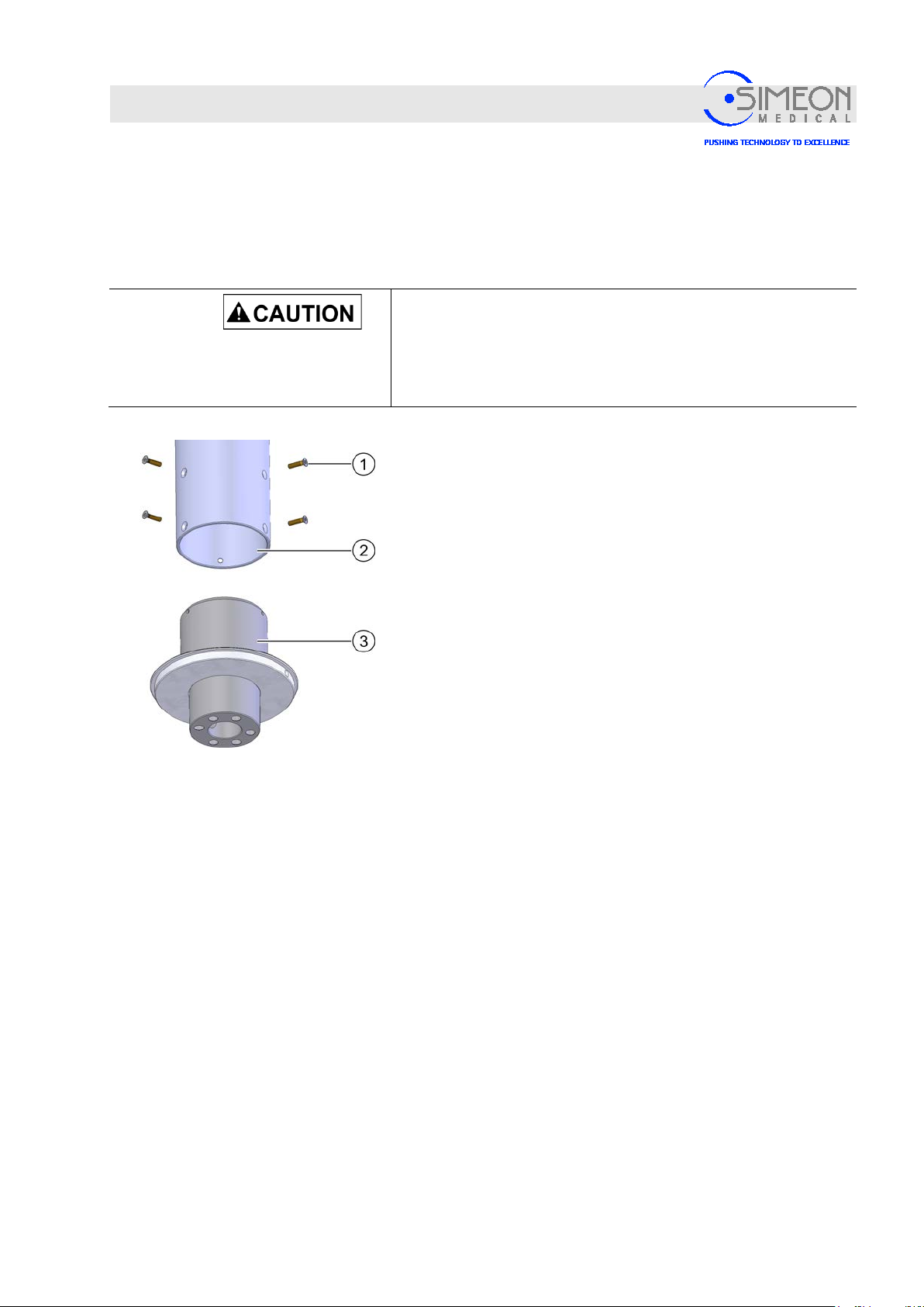
Fit Sim.FLEX adapter to round ceiling tube
The adapter enables the Sim.FLEX system to be mounted on a round ceiling tube.
Danger of injury from falling parts!
Since mounting the arms requires overhead work, injuries can be
caused by parts falling from above. This is especially the case if
not all of an extension arm's six mounting screws are correctly
tightened in sequence!
Insert the adapter (3) for the Sim.FLEX system into the round
ceiling tube from below, so that its threaded holes are visible
through the holes in the ceiling tube for the countersunk screws
(1).
Secure the adapter in the ceiling tube using the six socket head
countersunk screws (1). Tighten countersunk screws (1) with
torque spanner at 7 Nm.
The ceiling tube is now ready to mount the Sim.FLEX extension
arms.
The extension arms for the Sim.FLEX system are mounted on the
system's ceiling tube one after the other.
Mounting the extension arm
V. 1.7 32
Page 33
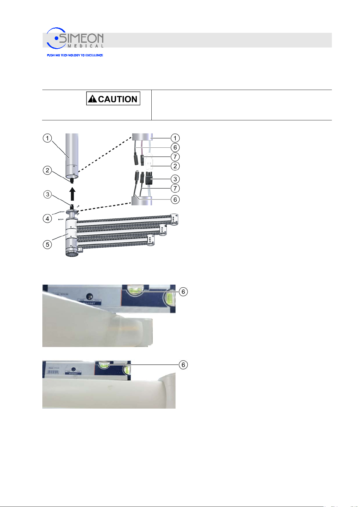
Installation Instructions Surgical LightingSim.LED 450/500/700/5000/7000 SC/MC
4.1.5 Mounting the round central axis
Mounting
Danger of injury from falling parts!
Since mounting the arms requires overhead work, injuries can be
caused by parts falling from above.
Variant: Power supply unit mounted in the control
cabinet, not on the ceiling tube
Power supply: Connect central axis plug (3) to the
plug socket (2) of the ceiling tube.
If there are multiple extension arms, the longest
cable is for the highest extension arm and the
shortest cable is for the lowest extension arm.
If present, connect the purple CAN bus cable (7).
If present, connect the black video signal cable
(6).
Variant: Power supply unit mounted onto the
ceiling tube
Insert the cable for the central axis upwards
through the ceiling tube, and connect it
professionally with the power supply unit that is
mounted to the ceiling tube and assigned to the
respective lights.
If there are multiple extension arms, the longest
cable is for the highest extension arm and the
shortest cable is for the lowest extension arm.
Both variants
Slide the central shaft (5) into the ceiling tube (1).
Screw in the M6 countersunk screws (4) and,
using a spirit level, align the central shaft so that
the extension arms are horizontal when extended
in every direction.
Tighten the M6 countersunk screws (4) by 7 Nm.
V. 1.7 33
Page 34
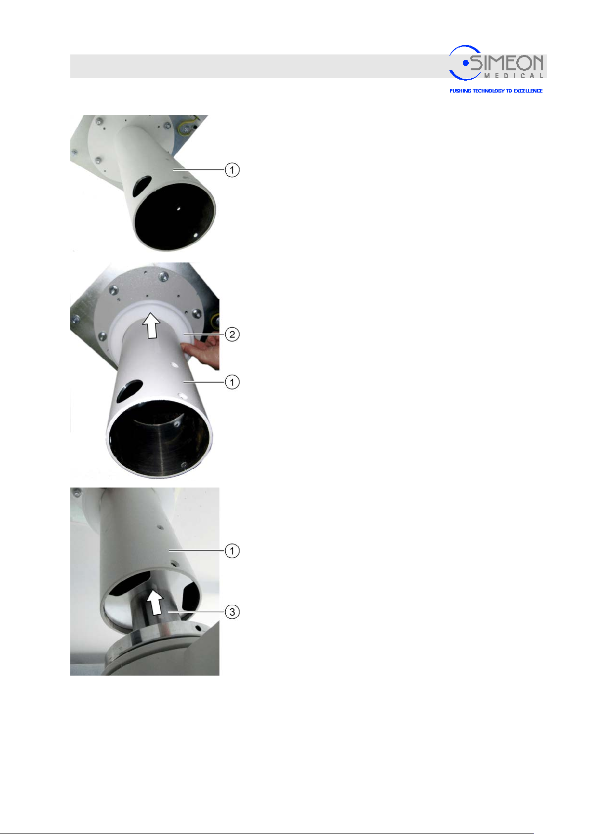
Installation Instructions Surgical LightingSim.LED 450/500/700/5000/7000 SC/MC
Mounting
Variant: Ceiling tube for TFT extension arms mounted at the
top, and power supply unit mounted to the ceiling tube
Mounting the ceiling tube, “Mounting the round ceiling tube or
Sim.FLEX”, page29.
Slide the silicone retaining ring (2) onto the ceiling tube (1) and
fasten it to the flange with adhesive tape to prevent it from fallin.
Properly mount the central axis (3),
“Mounting the round central axis”, page 33.
V. 1.7 34
Page 35
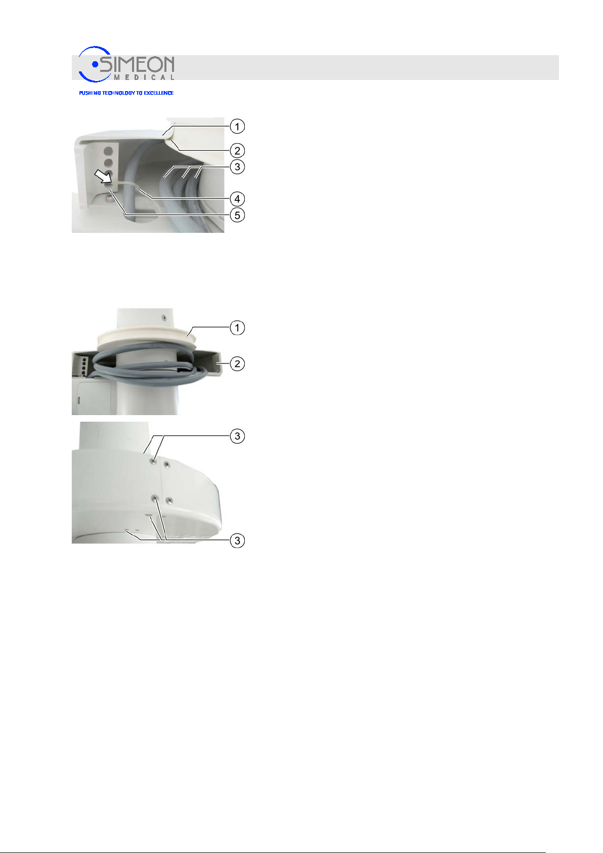
Installation Instructions Surgical LightingSim.LED 450/500/700/5000/7000 SC/MC
Mounting
Insert half (1) of the canopy cover into the groove (2) and screw
it tight.
Swing the extension arm clockwise until it hits the stop.
Loosely wind the cable around the ceiling tube clockwise in 3
windings (3). Fasten the cables to the perforated strip (5) with
cable ties (4).
Note: Choose the cables’ direction of rotation so that they
cannot be damaged when the extension arm is rotated between
the stop position!
Insert the cable for the central axis upwards through the ceiling
tube, and connect it professionally with the power supply unit
that is mounted to the ceiling tube and assigned to the
respective lights.
Remove the adhesive tape from the silicone retaining ring (1)
and apply the silicone retaining ring (1) to the canopy (2).
Mount second half of the canopy with the corresponding
countersunk screws (3).
V. 1.7 35
Page 36
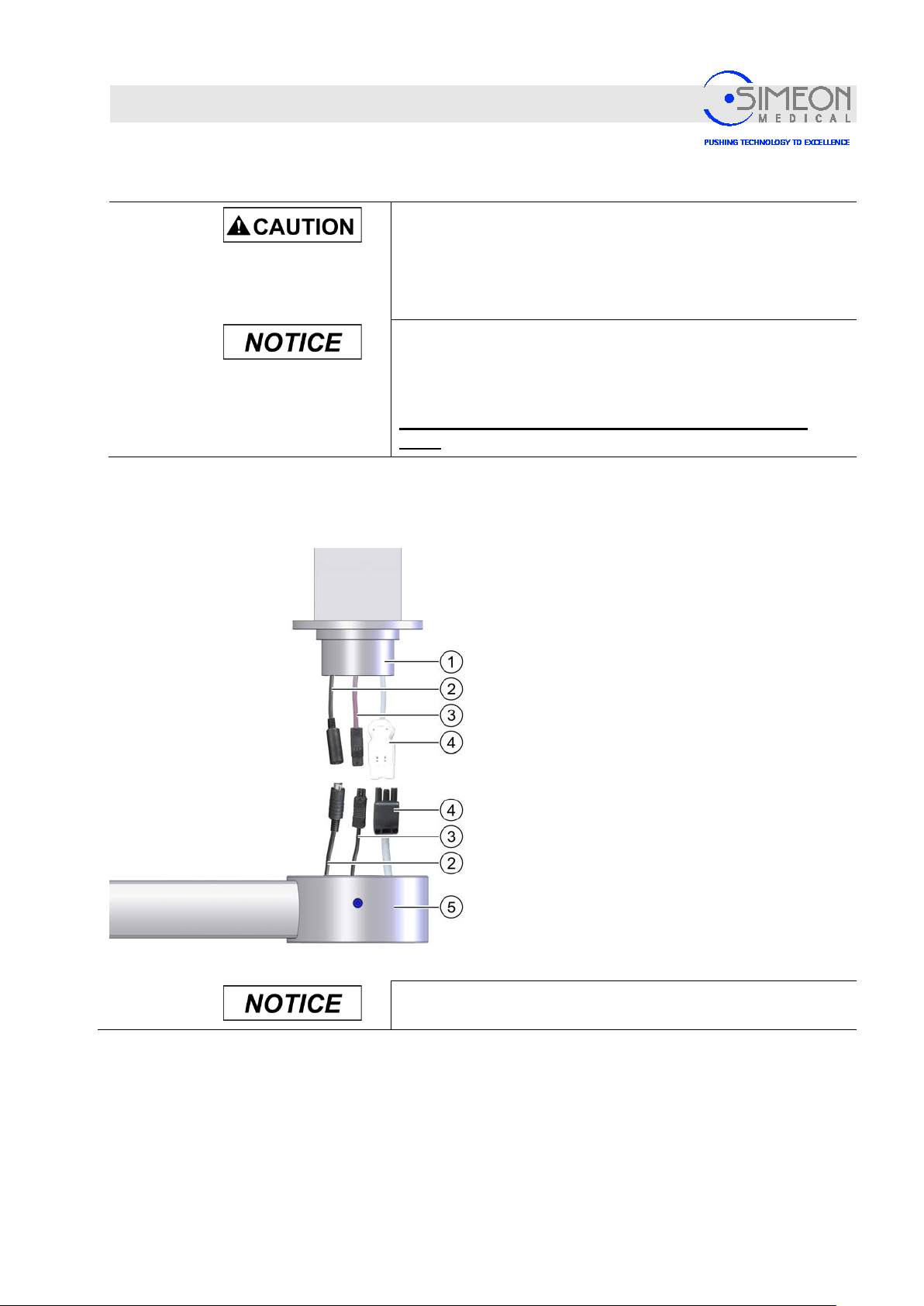
Installation Instructions Surgical LightingSim.LED 450/500/700/5000/7000 SC/MC
Mounting
4.1.6 Mount Sim.FLEX extension arms
The extension arms for the Sim.FLEX system are mounted on the system's ceiling tube one after the other.
Each extension arm is mounted in the same way:
Danger of injury from falling parts!
Since mounting the arms requires overhead work, injuries can be
caused by parts falling from above. This is especially the case if
not all of an extension arm's six mounting screws are correctly
tightened in sequence!
Mount the silicone retaining ring before the extension arms!
Before mounting the extension arms, the silicone retaining ring
that accommodates the ceiling tube cover must be correctly
mounted, “Mounting the ceiling tube for Sim.FLEX“, page 31.
This is no longer possible after mounting the extension
arms!
With the rotating canopy open, position the extension
arm (5) below the central shaft (1).
Connect the grey power supply cable (4).
If present, connect the purple CAN bus cable (3).
Connect the black video signal cable (2), if present
(Caution: Please observe HD Touch connections)
Connecting the Sim.CAM HD Touch on separate
extension arm
Before screwing on the extension arm, ensure that all six M12
screws can be inserted!
V. 1.7 36
Page 37
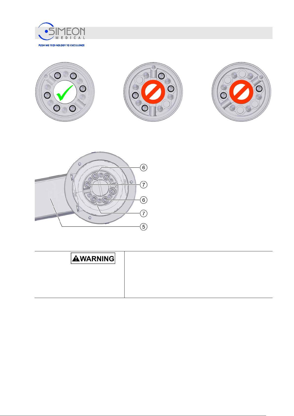
Installation Instructions Surgical LightingSim.LED 450/500/700/5000/7000 SC/MC
All 6 threaded holes accessible:
Proceed with assembly
Only 4 threaded holes accessible:
Do not proceed with assembly!
Hold the extension arm (5) below the central shaft so
that the threaded holes are visible for all six M12
screws (6, 7).
Mounting
Only 2 threaded holes accessible:
Do not proceed with assembly!
Secure the extension arm using two diametrically
opposed M12 screws (6).
Now fit and hand-tighten the remaining M12 screws
(7).
Now tighten all six M12 screws (6, 7) using a torque
spanner set to 140 Nm.
Mount the remaining extension arms in the same way.
Danger of injury from falling parts!
Errors during assembly can compromise the stability of the
lighting system. This can cause the system to collapse,
potentially resulting in extremely serious injuries.
Fit and tighten all six M12 mounting screws correctly for each
extension arm!
V. 1.7 37
Page 38
Installation Instructions Surgical LightingSim.LED 450/500/700/5000/7000 SC/MC
Mounting
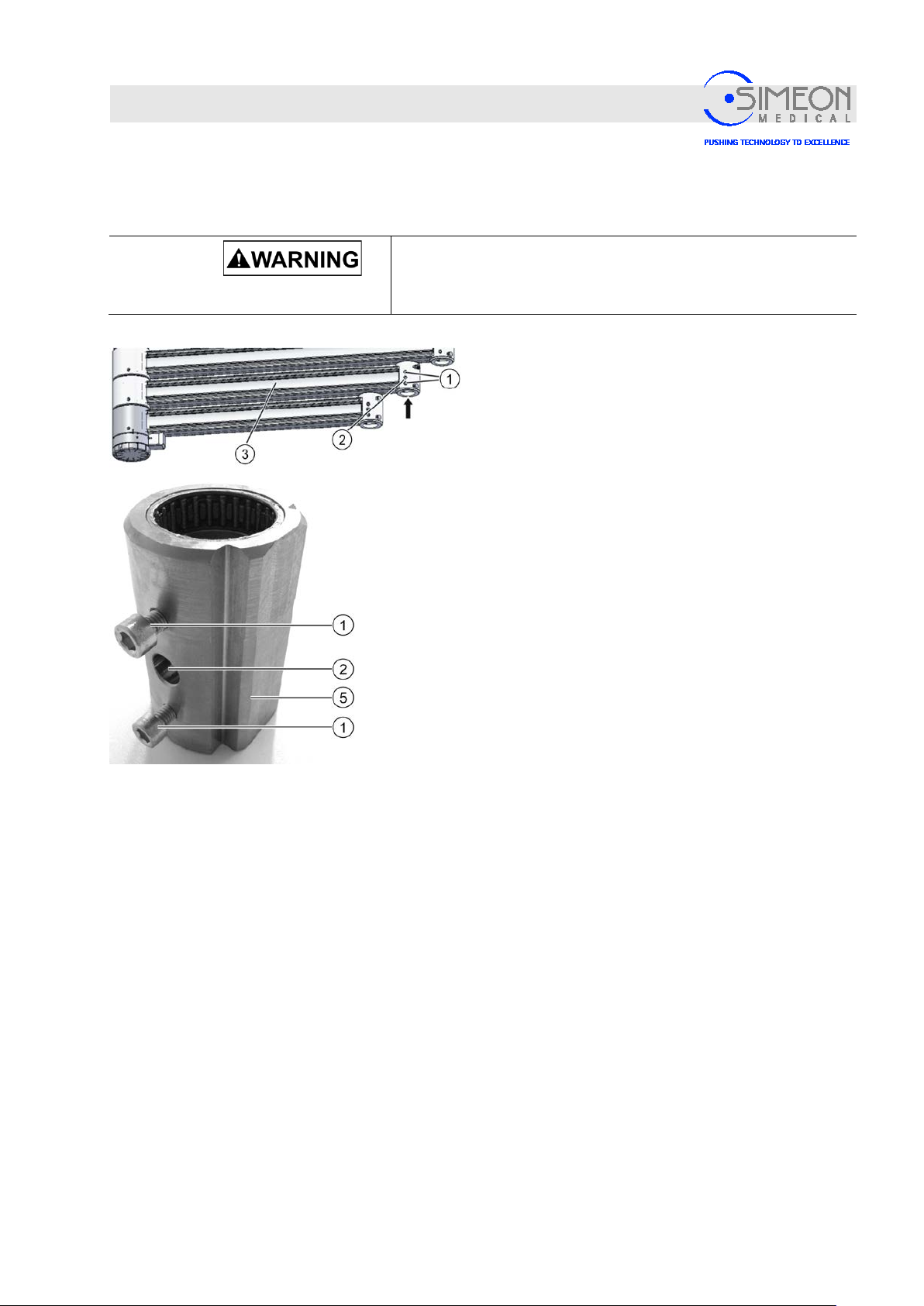
4.1.7 Mounting adapter on spring arm / spring arm on extension arm
Supplier variant “Socket mounted on the extension arm"
Danger of injury from falling parts!
Since mounting the arms requires overhead work, injuries can be
caused by parts falling from above.
In this variant, the socket is delivered mounted on the
extension arm (3) (see arrow).
Loosen two cylinder screws M6 (1) from the extension
arm (3).
Put your hand under the opening in the socket and
secure it to prevent it from falling.
Remove the brake screw (2) from the threaded hole.
Remove the socket (5) downwards from the extension
arm and set aside.
Ensure that the needle bearings mounted at the top
and bottom of the bushing do not fall out.
V. 1.7 38
Page 39
Installation Instructions Surgical LightingSim.LED 450/500/700/5000/7000 SC/MC
Risk of injury due to a collapsing spring arm!
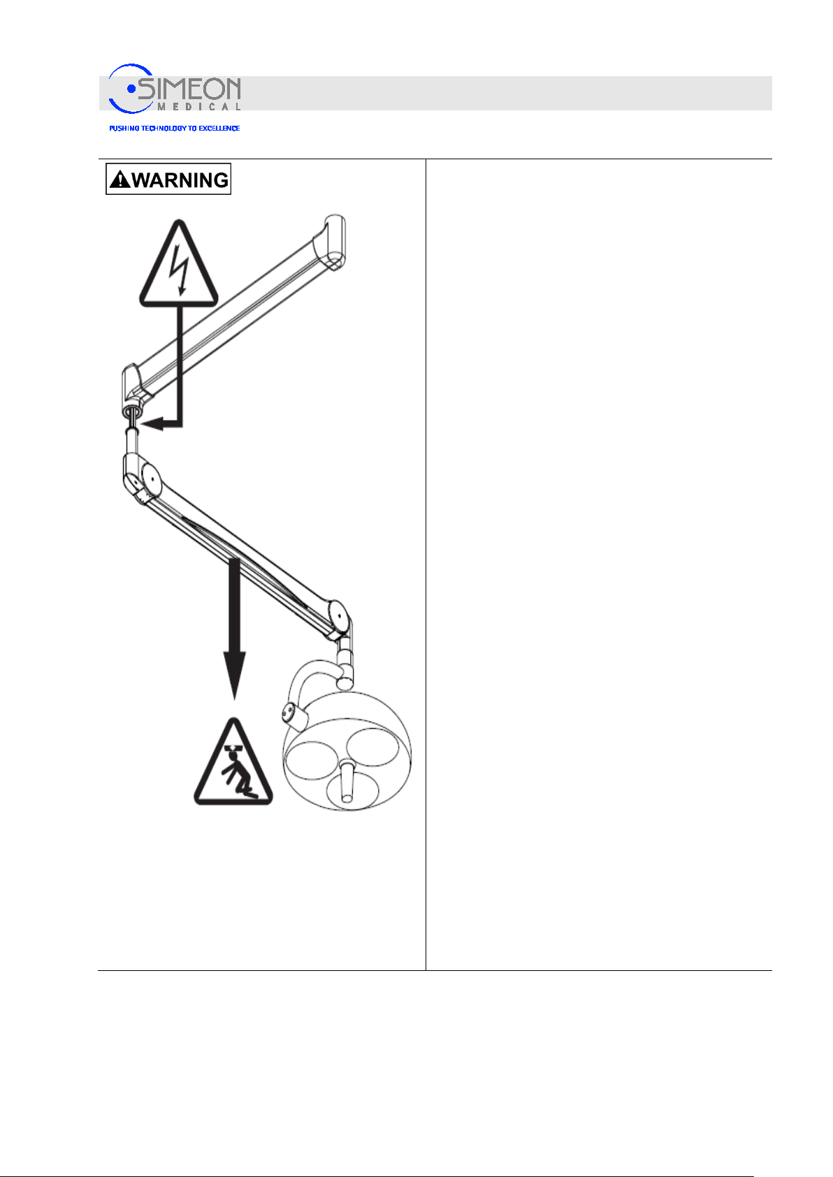
The locking ring may not be overstretched and must
properly snap into the groove when mounted!
Otherwise, injuries may be caused by falling parts!
The locking ring may not be overstretched and must
properly snap into the groove when mounted!
Otherwise, injuries may be caused by falling parts!
The spring arm, adapter (e.g. handle) and the end
device (e.g. flat screen, surgical lights, etc.) are held
in position by a locking ring in the spring arm.
If the locking ring is overexpanded or incorrectly
mounted during disassem bly or mounti ng, it wil l fall
out of the groove in the spring arm. As a result, the
spring arm, adaption and end device will fall, possibly
tearing out internal electrical supply lines. This can
cause severe injuries:
Mounting
• The locking ring may only be installed by trained
and authorised qualified personnel.
• Suitable circlip pliers with expansion control must
be used.
• The installation instructions and installation order
must be complied with.
• Only use the locking ring removed in the initial
installation one time, or use a new, unus ed locking
ring.
• In service or maintenance cases, a new, unused
locking ring will have to be used.
• Check to make sure the locking ring is seated firmly
according to manufacturer specifications!
V. 1.7 39
Page 40
Installation Instructions Surgical LightingSim.LED 450/500/700/5000/7000 SC/MC
Mounting
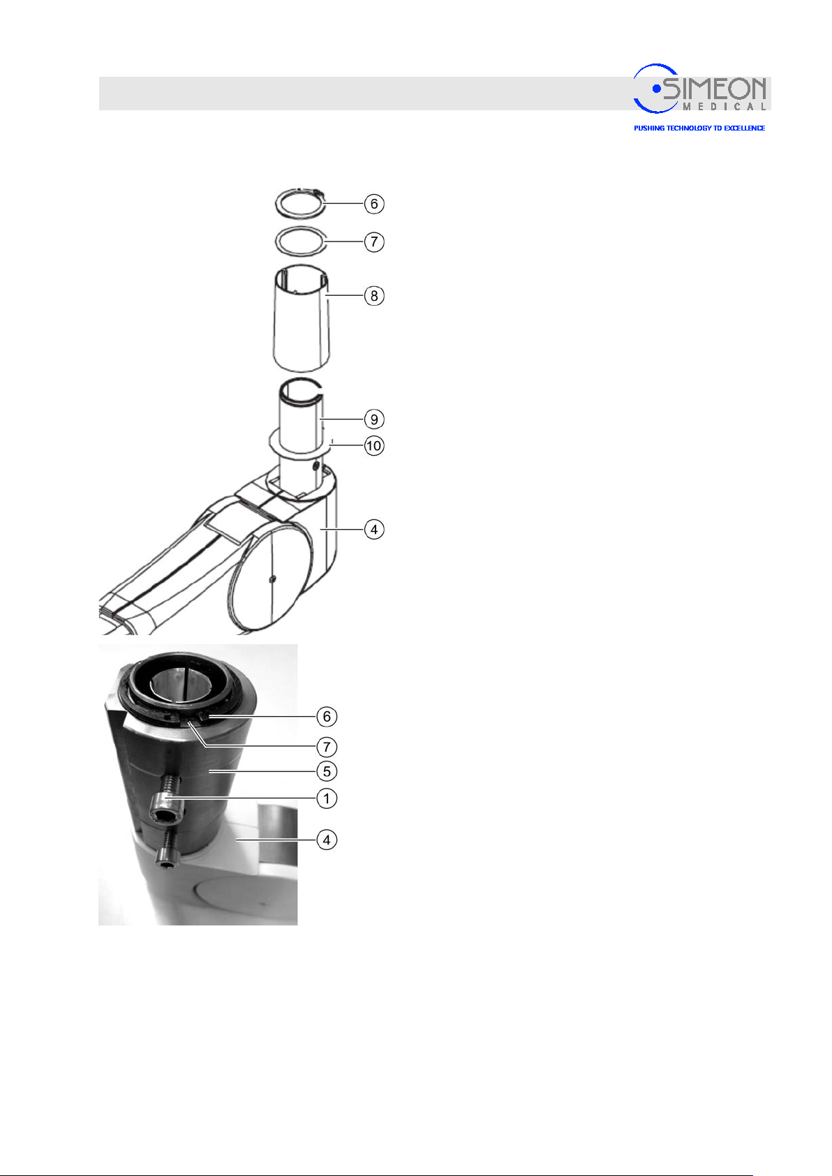
Dismantle locking ring (6), washer (7) and protective
sleeve (8) according to manufacturer’s assembly
instructions.
Insert the sleeve (5) on the pivot (9) of the spring arm
(4).
Mount the washers (7) - the pivot groove for the
locking ring (6) remains free in the process.
Mount locking ring (6) according to manufacturer’s
specifications!
V. 1.7 40
Page 41
Installation Instructions Surgical LightingSim.LED 450/500/700/5000/7000 SC/MC
Mounting
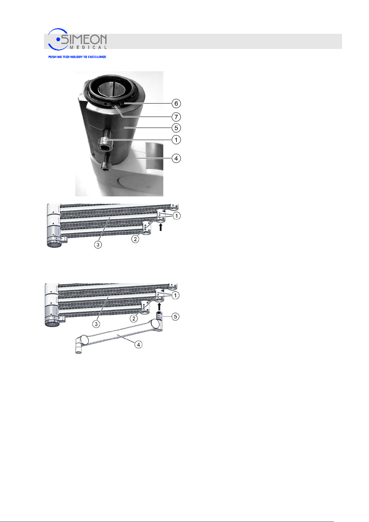
Identify the spring arm by the product label (3
pol./5 pol./9 pol./TFT) and allo cate the
corresponding spring arm of the central axis or
Sim.Flex to the installation. Incorrect allocation
may damage the central axis and spring ar m!
Precisely align the spring arm with sleeve (5)
horizontally and vertically and insert into the
extension arm as far it will go so that the threaded
holes for the cylinder screws (1) are aligned with
the boreholes in the extension arm.
Fasten the spring arm with the cylinder screws M6
(1) and tighten with torque spanner at 8 Nm.
Insert and tighten the brake screw (2) for the spring
arm “Setting the braking power “, page 112.
Supply variant "Socket pre-mounted on the spring arm"
Remove the brake screw (2) from the end of the
extension arm.
Place the spring arm pivot with sleeve (5) in the
extension arm (3) in such a manner, that the
threaded holes are aligned with the holes (1) in
the extension arm.
Tighten the spring arm using the cylinder screws
M6 in the holes (1).
Insert and tighten the brake screw (2) for the
spring arm “Setting the braking power“, page
112.
V. 1.7 41
Page 42
Installation Instructions Surgical LightingSim.LED 450/500/700/5000/7000 SC/MC
Mounting
4.1.8 Mounting adapter on spring arm / mounting spring arm on Sim.FLEX extension arm
Danger of injury from falling parts!
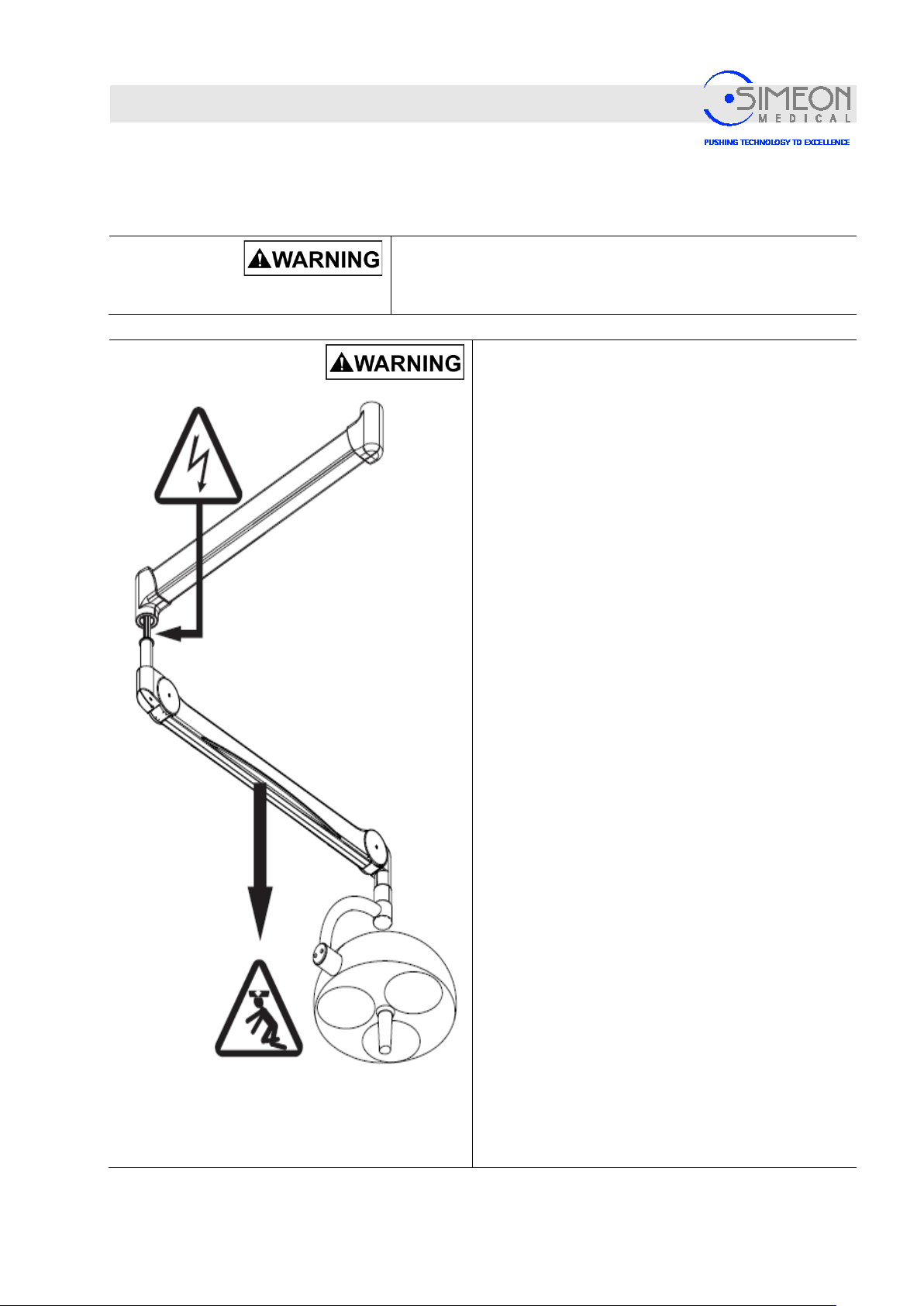
Since mounting the arms requires overhead work, injuries can be
caused by parts falling from above.
Risk of injury due to a collapsing spring arm!
The locking ring may not be overstretched and must
properly snap into the groove when mounted!
Otherwise, injuries may be caused by falling parts!
The locking ring may not be overstretched and must
properly snap into the groove when mounted!
Otherwise, injuries may be caused by falling parts!
The spring arm, adaption (e.g. handle) and the end
device (e.g. flat screen, surgical lights, etc.) are held
in position by a locking ring in the spring arm.
If the locking ring is overexpanded or incorrectly
mounted during disassem bly or mounti ng, it wil l fall
out of the groove in the spring arm. As a result, the
spring arm, adaption and end device will fall, possibly
tearing out internal electrical supply lines. This can
cause severe injuries:
• The locking ring may only be installed by trained
and authorised qualified per s onnel.
• Suitable circlip pliers with expansion control must
be used.
• The installation instructions and installation order
must be complied with.
• Only use the locking ring removed in the initial
installation one time, or use a new, unused locking
ring.
• In service or maintenance cases, a new, unused
locking ring will have to be used.
• Check to make sure the locking ring is seated firmly
according to manufacturer specifications!
V. 1.7 42
Page 43
Installation Instructions Surgical LightingSim.LED 450/500/700/5000/7000 SC/MC
Mounting
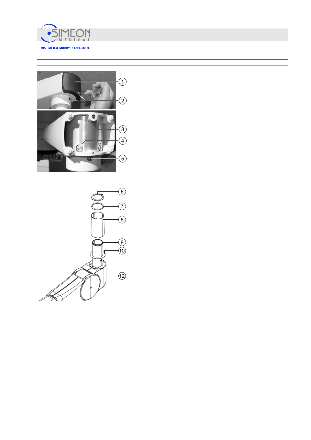
The extension arm is supplied with the bushi ng alre ady fitted.
Use a hexagon spanner to remove the retaining screw (2) from
the extension arm cap (1).
Lay the cap and screw to one side.
Undo two M8 cylinder screws (4) from the socket (3).
Put your hand under the opening in the socket and secure it to
prevent it from falling.
Remove the brake screw (5) from the threaded hole.
Remove the socket (3) downwards from the extension arm
and set aside.
Ensure that the needle bearings mounted at the top and
bottom of the socket (3) do not fall out.
Dismantle locking ring (6), washer (7) and protective sleeve
(8) according to manufacturer’s assembly instructions.
V. 1.7 43
Page 44
Installation Instructions Surgical LightingSim.LED 450/500/700/5000/7000 SC/MC
Mounting
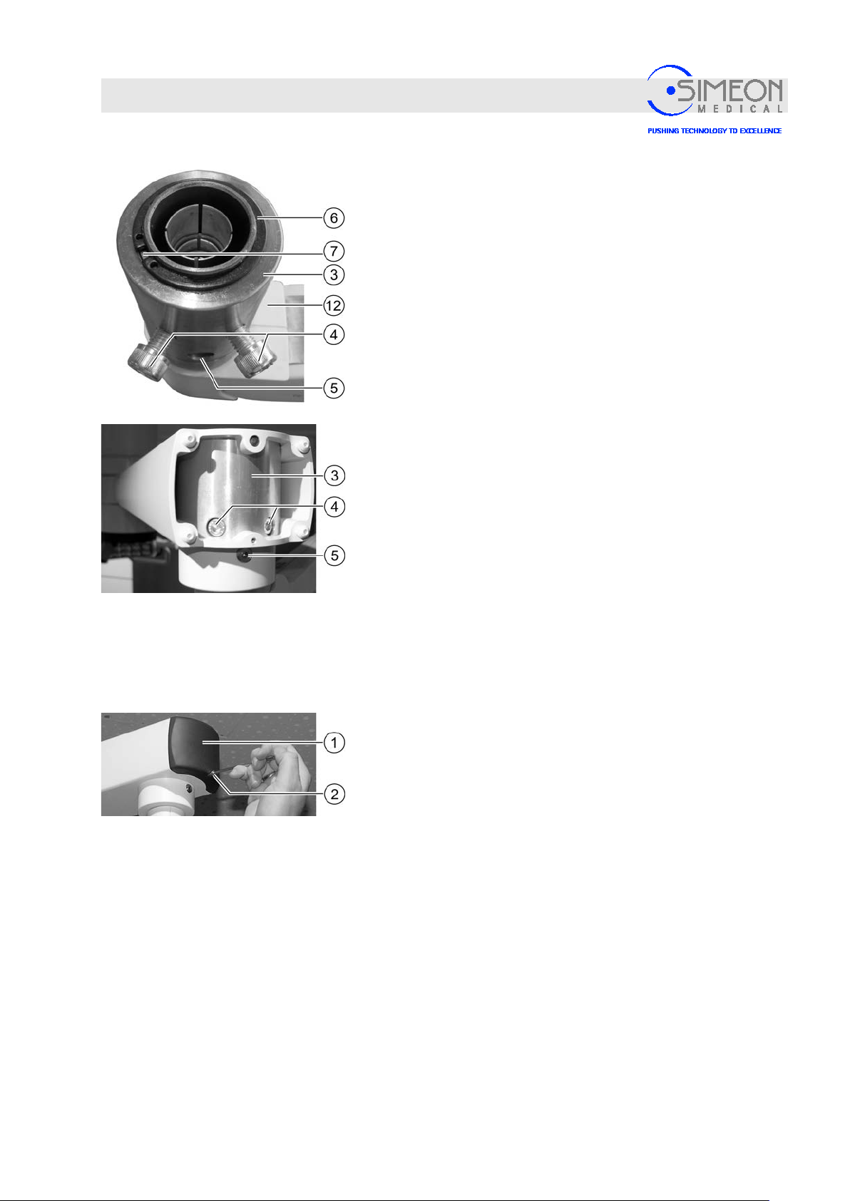
Insert the sleeve (5) on the pivot of the spring arm (12).
Mount the washers (7) - the pivot groove for the locking ring
(6) remains free in the process.
Mount locking ring (6) according to manufacturer’s
specifications!
Identify the spring arm by the product label (3 pol./5
pol./9 pol./TFT) and allocate the corresponding Sim.Flex
spring arm to the installation. Inc o rrect allocation may
damage the slip ring, Sim.Flex extensi o n ar m and spring
arm.
Precisely align the spring arm with sleeve (5) horizontally
and vertically and insert into the extension arm as far it will
go so that the threaded holes for the M8 cylinder screws (4)
are aligned with the boreholes in the extension arm.
Tighten the spring arm using the M8 cylinder screws (4) in
the extension arm, using a torque spanner set to 20 Nm.
Insert and tighten the brake screw (5) for the spring arm
“Setting the braking power“, page 112.
Replace the cap (1).
Insert the retaining screw (2) into the extension arm cap (1)
and use a hexagon spanner to tighten gently.
V. 1.7 44
Page 45
Installation Instructions Surgical LightingSim.LED 450/500/700/5000/7000 SC/MC
4.1.9 Mounting spring arm adapter (optional delivery variant)
Mounting
Danger of injury from falling parts!
Since mounting the arms requires overhead work, injuries can be
caused by parts falling from above.
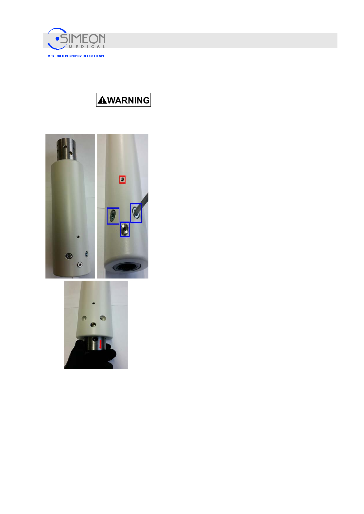
The sleeve is installed in the adapter upon delivery.
Identify the adapter by the product label (3 pol./5 pol./9
pol./TFT) and allocate the corresponding spring arm of the
central axis or Sim.Flex to the installation. The adapter can be
installed with normal central axes as well as the Sim.Flex
extension arm. Incorrect allocation may damage the adapter,
central axis/Sim.Flex and spring arm.
Remove the sleeve installed in the bottom side of the adapter.
To do so, remove the mounting screws (marked blue) and
brake screws (marked blue). The 2nd brake screw is offset by
180° on the back side. Do not turn the red marked screws!
Carefully remove the sleeve installed in the adapter bottom
side in the axial direction without using tools. In doing so,
make sure not to touch or damage the inner slip ring!
V. 1.7 45
Page 46
Installation Instructions Surgical LightingSim.LED 450/500/700/5000/7000 SC/MC
Mounting
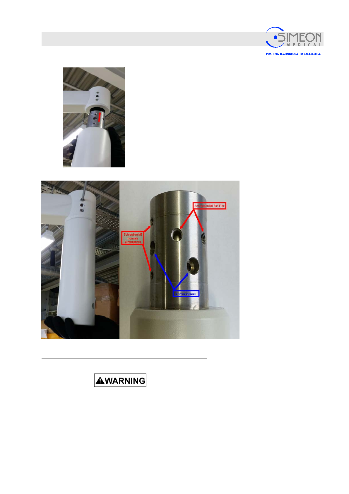
Align the adapter so that it is absolutely horizontal and
vertical and carefully insert it into the extension arm as far as
it will go.
With a normal
central axis,
screw in the M6
screws and
tighten at 8 Nm
with a torque
spanner.
Mount sleeve on spring arm accordi n g to p age 37 and/or 42
Risk of injury due to a collapsing spring arm!
The locking ring may not be overstretched and must properly
snap into the groove when mounted! Otherw ise, inj urie s ma y
be caused by falling parts!
Sim.Flex
variant:
Screw in the M8
screws and
tighten at 14 Nm
with a torque
spanner.
Screw brake
screw in flush
accordingly.
V. 1.7 46
Page 47
Installation Instructions Surgical LightingSim.LED 450/500/700/5000/7000 SC/MC
Mounting
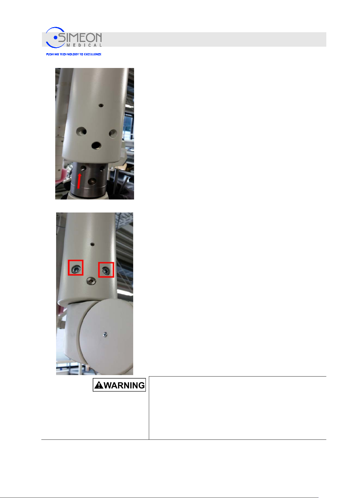
Align the spring arm with mounted sleeve so that it is
absolutely horizontal and vertical and correctly positioned
based on the holes and carefully insert into the adapter as
far as it will go.
Screw in the M8 screws and tighten at 20 Nm with a torque
spanner.
Screw brake screws in on the front and back side and set
brake force as needed. Turn the brake screw in a clockwise
direction, using the Allen key, to increase the braking power.
Turn the brake screw counterclockwise to decrease it.
V. 1.7 47
Risk of injury due to incorrect mounting!
Incorrect or unsafe mounting of the assembled device may lead
to life-threatening situations and cause significant material
damage. Thus, please note:
− The adapters are not meant to be attached to one another;
instead, only one is to be attached to each central axis
extension arm.
Page 48
Installation Instructions Surgical LightingSim.LED 450/500/700/5000/7000 SC/MC
Mounting
4.1.10 Mounting the light heads onto the spring arm
Danger of injury from falling parts!
Since mounting the arms requires overhead work, injuries can be
caused by parts falling from above.
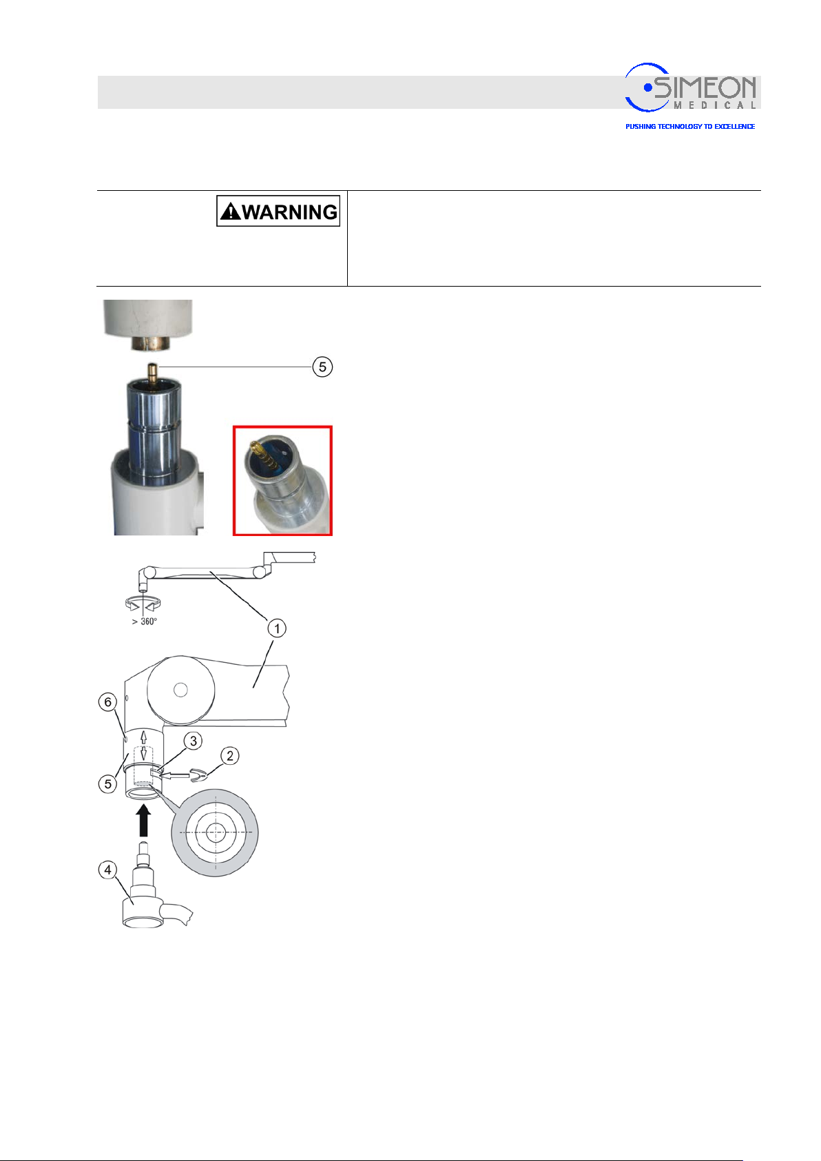
The safety sleeve must be attached and screwed tightly!
Note: When placing the pivot in the spring arm, ensure that the
turning connector (5) is not damaged!
For this purpose, remove the turning connector's protective
cap only shortly before insertion, and carefully align the pin
parallel to the LC spring arm.
A damaged turning connector cannot be used and must be
disposed of.
Bring the spring arm (1) into position.
Loosen and remove the sleeve's retaining screw (6).
Slide the safety sleeve (5) upwards and af f ix .
Remove safety piece (2).
Insert the cardanic's (4) pins carefully and vertically into the
spring arm (1), until the pin's groove can be located in the
safety piece's opening (3).
Insert the safety piece (2) and slide the safety sleeve (5)
downwards.
Screw tightly the sleeve's retaining screw (6).
The light head is safely connected to the spring arm (1).
V. 1.7 48
Page 49
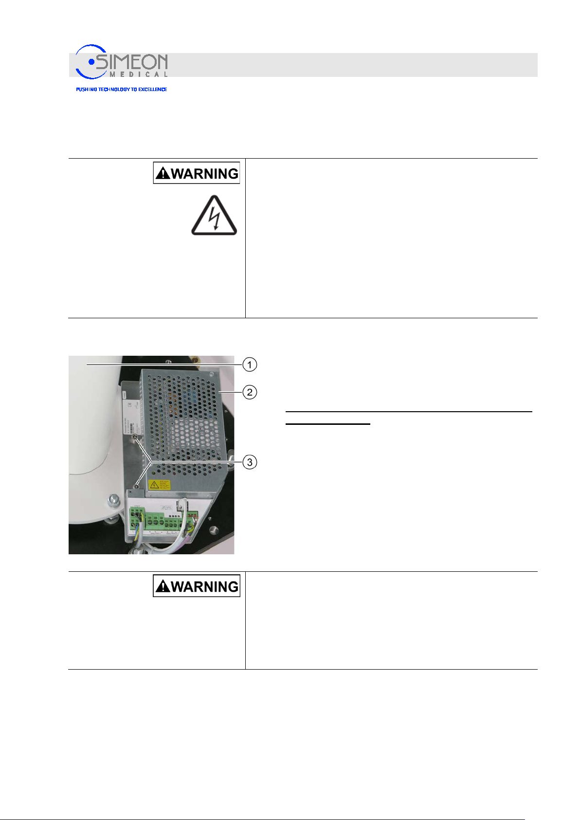
Installation Instructions Surgical LightingSim.LED 450/500/700/5000/7000 SC/MC
Mounting
4.1.11 Mounting and connecting the power supply unit for surgical lights to the ceiling tube
Danger of electric shock!
A switch is to be provided on-site as a disconnector from the
mains power supply which disconnects the system from the
mains power supply at all poles simultaneously This switch must
meet the creepage and air distance requirements set forth in IEC
61058-1 for a mains voltage peak of 4 kV. The activation device
for this switch must meet the requirements of IEC 60447.
If the switch is not visible to the maintenance personnel, it will
have to be possible to lock it in the OFF position.
The locking mechanism may be located in the mains power
supply switch of the organisation in charge.
The sample image shows a switching power supply mounted
on a ceiling tube. The switching power supply can also be
mounted externally in a control cabinet.
Switch off the building's power supply and safeguard
against restarting!
Screw in the power supply unit (2) using 2 screws M8 (3),
with spring washer and washer on the threaded holes
intended for this purpose, to the ceiling tube's (1) flange.
V. 1.7 49
Applied voltage may damage or destroy the components to
be installed!
Disconnect the on-site power supply from the mains and secure it
to prevent reconnection when
conducting any installatio n work !
Page 50
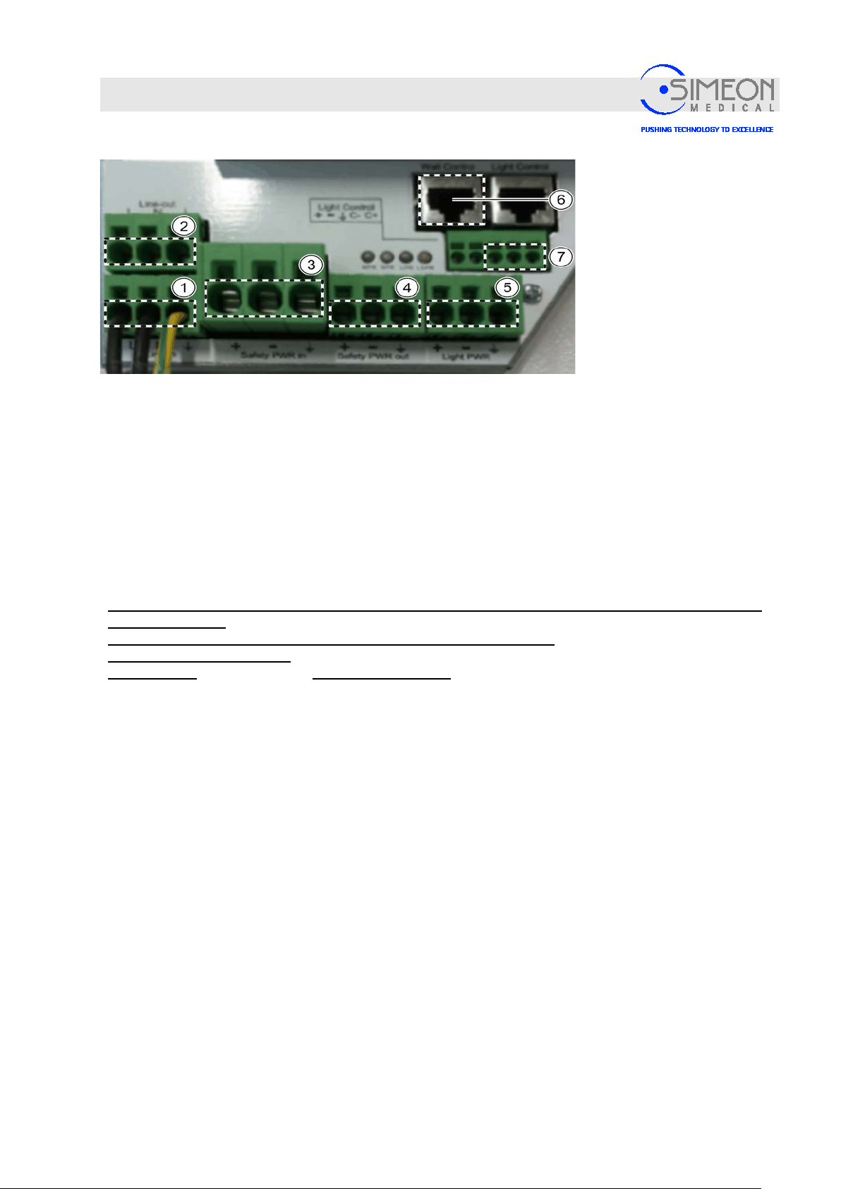
Installation Instructions Surgical LightingSim.LED 450/500/700/5000/7000 SC/MC
1
Line in 100 – 240 V AC (L, N, PE)
5
Connection to lights 28V DC (+, -, PE)
2
Line out 100 – 240 V AC (L, N, PE)
6
Connection to the wall control unit
3
Safety Power in 28 V DC+1% -8% (+, -, PE)
7
CAN connection to the lights (PE CAN+, CAN-)
4
Safety Power out 28 V DC +1% -8% (+, -, PE)
Line in
L
Phase
Approved cable lengths for 28V DC direct-current voltage from power supply to central axis (max.
Maximum power: 130 watts
Cable length:
Cable cross-section:
Mounting
Connect a Ø 2.5mm2 cable to Line in (1) of the on-site power supply:
Caution: “Safety Power in” is not controlled. High voltages outside of the toleran ce will lead to
defects or destroy the connected devices!
Line out
voltage drop 5%):
Ambient temperature for approved cable lengths: max. 50° Celsius
≤ 18 metres
> 18 metres and ≤ 30 metres
> 30 metres and ≤ 45 metres
N
PE
2.5mm²
4.0mm²
6.0mm²
Neutral conductor
Grounding conductor
V. 1.7 50
Page 51
Installation Instructions Surgical LightingSim.LED 450/500/700/5000/7000 SC/MC
Mounting
Risk of injury due to light/camera malfunction!
In order to safeguard against the possibility of a lighting system outage,
every switching power supply on site must be powered by a separate feed
line!
Each light must be supplied with a separate switching power supply.
Each camera on a separate arm must be supplied with a separate
switching power supply.
The Line out outputs (2) are only used to supply an optional, medically
approved display (with 100 – 240V AC, if possessing country- / regionspecific approval).
Risk of injury due to voltage fluctuations!
The mains power supply must satisfy overvoltag e category II in
terms of the mains transients. Voltages above 110 % or below 90 %
of the voltage's nominal value may not arise between arbitrary
conductors of the system or between one of these conductors and
earth. The client must also offer Simeon products protection against
excessively high start-up currents.
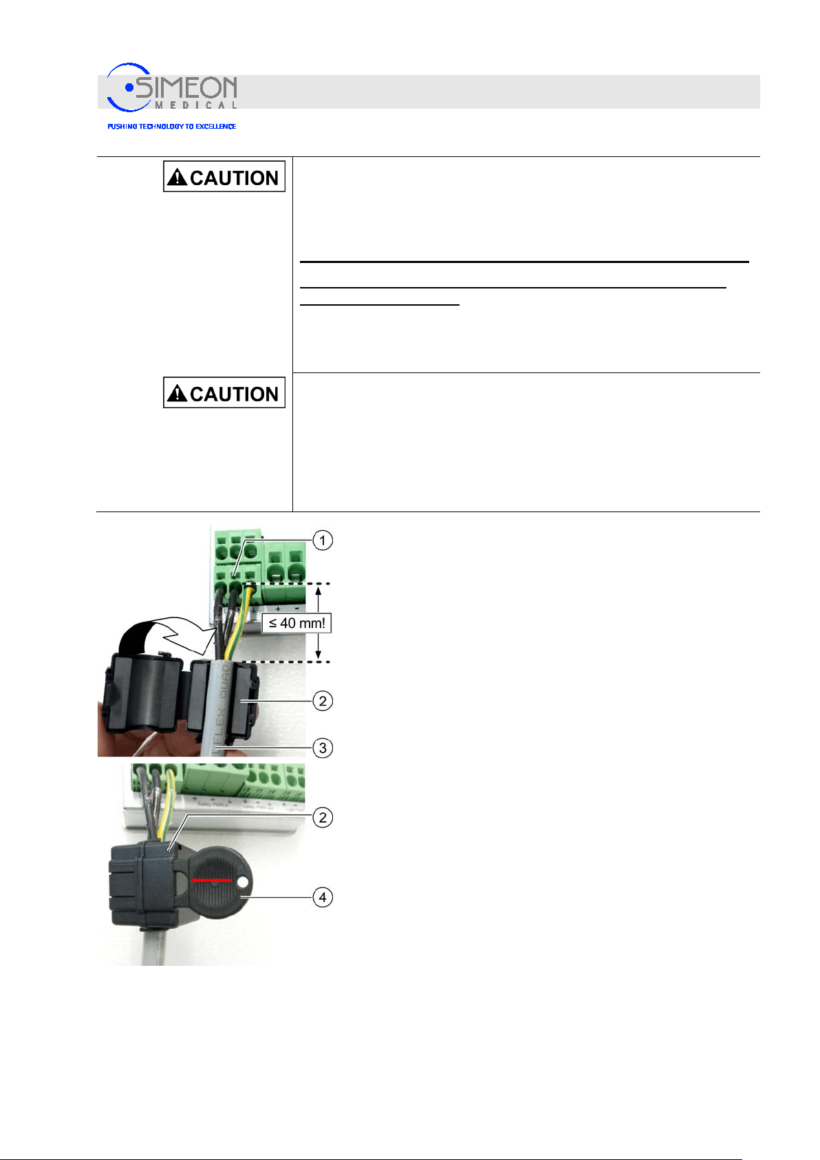
Next, affix the ferrite core (2) to the Line in (1) mains supply
line. To do so, place the ferrite core around the cable and
allow the ferrite core's snap lock to snap into place. If the cable
is not securely clamped by the ferrite core, secure the ferrite
core in position (3) against sliding using a cable tie.
Make sure that the ferrite core is not mounted at a distance
greater than 40 mm from the terminal (1).
The ferrite core (2) can be dismounted and readjusted using a
specific key (4).
V. 1.7 51
Page 52
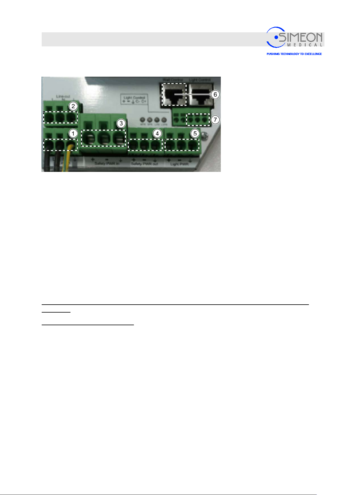
Installation Instructions Surgical LightingSim.LED 450/500/700/5000/7000 SC/MC
1
Line in 100 – 240 V AC (L, N, PE)
5
Connection to lights 28V DC (+, -, PE)
2
Line out 100 – 240 V (L, N, PE)
6
Connection to the wall control unit
3
Safety Power in 24 – 28 V DC +1% -8% (+, -, PE)
7
CAN connection to the lights (PE CAN+, CAN-)
4
Safety Power out 24 – 28 V DC +1% -8% (+, -, PE)
+
Lighting supply + 28 VDC, “1”, SW
Lighting supply
Lighting supply grounding conductor GNYE
+
Input + 24 – VDC
Input
Grounding conductor
Mounting
Function test
Switch on-site power supply on and check whether the LED MPR above the Safety Power out (4)
lights up.
− If it does not, then check whether the on-site power supply is correctly connected to the Line in (1).
− If it is, then use a voltmeter to check at Line in (1) whether the on-site power supply is correctly
connected.
− If this is the case, then the power supply is defective.
Switch off the building's power supply and safeguard against restarting.
If necessary, replace the power supply and repeat the function test.
After a successful function check, switch off the building's power supply and safeguar d against
restarting!
Without voltage on power supply
Connect 3-wire cable (colour: grey) from the central axis to the lighting supply to Light Power (5) (+, -,
PE):
PE
The black wires of the lighting voltage + and - are stamped with “1” and “2.”
Optional: Connect exis ti ng emergency power supply to Safety Power in (3).
PE
V. 1.7 52
- (0 V)
- 2”, SW
Page 53
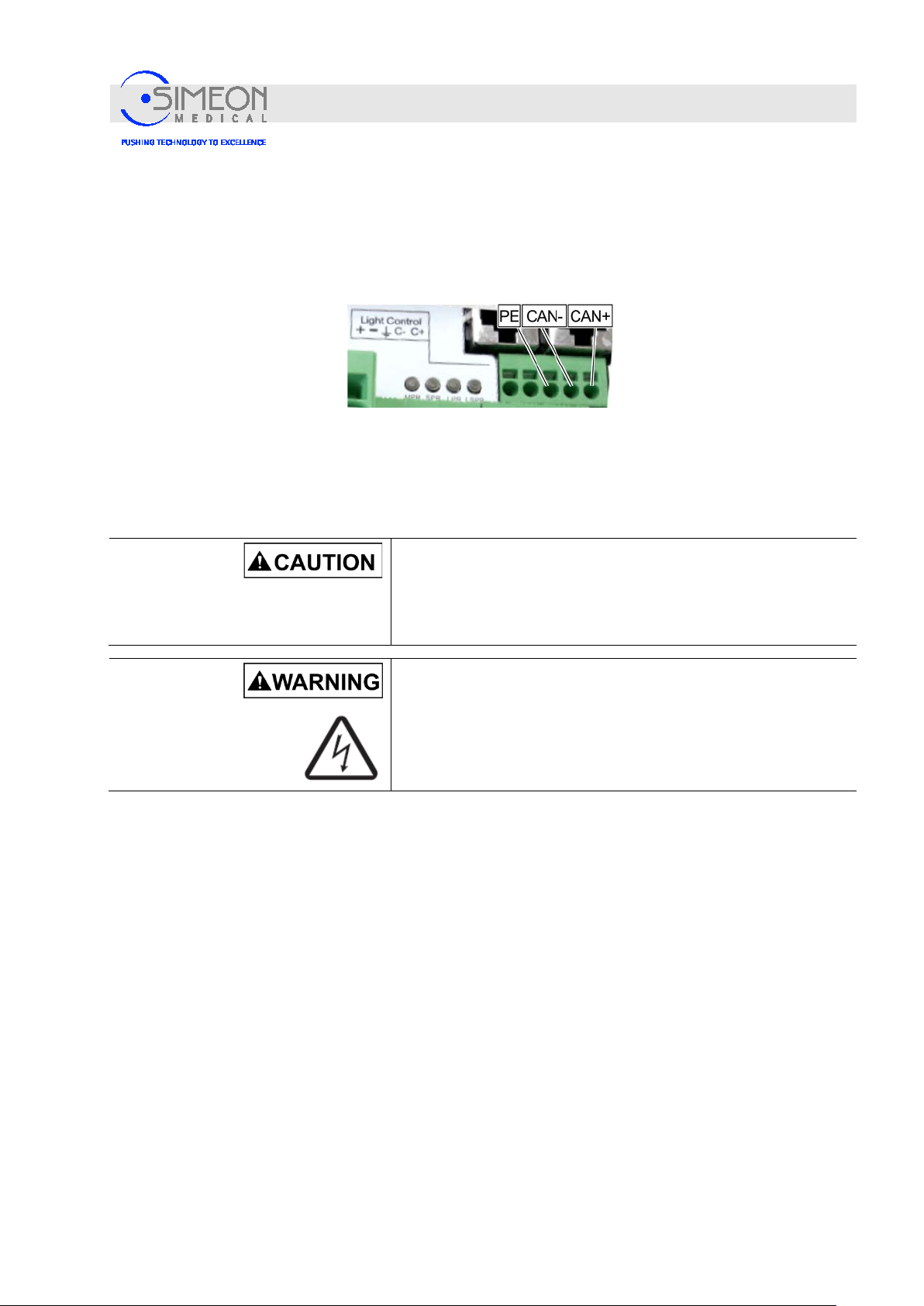
Installation Instructions Surgical LightingSim.LED 450/500/700/5000/7000 SC/MC
Brown:
CAN+
CAN
Grounding
shield
Mounting
If Safety Power in (3) is not supplied with power, Safety Power out (4) will also have no power.
Connect the purple cable from the central axis to the terminal block (7) for CAN communication with
the light:
White:
Black:
-
Connect the RJ45 patch cable from the wall control unit to Wall Control (6) for communication with
the wall control unit.
4.1.12 Installing the Sim.INTERFACE
The Sim.INTERFACE requires 1 installation place on the ceiling tube.
Danger of injury from falling parts!
Since mounting the arms requires overhead work, injuries can be
caused by parts falling from above.
The safety sleeve must be attached and screwed tightly!
Danger of electric shock!
The on-site supply line must be disconnected from the mains on
site before further work may be performed! The supply line must
be secured to prevent reconnection.
V. 1.7 53
Page 54
Installation Instructions Surgical LightingSim.LED 450/500/700/5000/7000 SC/MC
Mounting
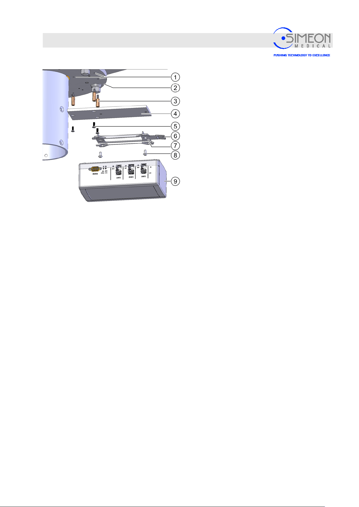
Screw the three M4 x 20 mm spacer bolts (3)
into the threaded holes (1) in the ceiling tube
flange (2).
Screw the retainer (4) onto the spacer bolts (3)
with the three countersunk head screw
M4 x 15 mm (5).
Screw the Sim.INTERFACE wall bracket (7) to
the retainer (4) with the two Allen screws (8).
Slide the Sim.INTERFACE (9) onto the wall
bracket (7) until it snaps into place.
In order to release the snap connection, push
up on the lever (6) slightly until the
Sim.INTERFACE (9) can be slid out.
V. 1.7 54
Page 55
Installation Instructions Surgical LightingSim.LED 450/500/700/5000/7000 SC/MC
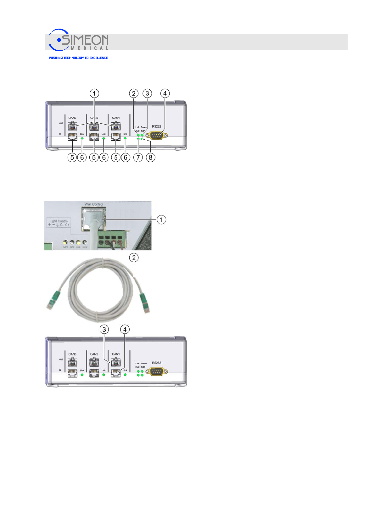
2
LED display RS232 Link (link status)
3
LED display Power
4
Connection RS232
6
LED displays for link status CAN1 to 3
7
LED display RS232 RxD
8
LED display RS232 TxD
Connecting the Sim.INTERFACE
Mounting
4.1.13 Connecting the Sim.INTERFACE
Connections of the Sim.INTERFACE
1 OUT outputs (wall control units) CAN1 to CAN3
5 IN inputs (power supplies for lights) CAN1 to 3
Power supply and wall controls are connected to the CAN1, CAN2 or CAN3 of the Sim.INTERFACE by one
connection cable each. The interface is connected to an interface card such as OR1 with its RS232 interface
(4) in an integrated OR. This integrated OR is then used to control the surgical lights and cameras.
If further surgical lights are connected, repeat the steps described above. The connection lines must be
plugged into CAN2 and/or CAN3 at the Sim.INTERFACE.
Plug the patch cable (2) on the power supply into
the RJ45 socket Wall Control (1).
Plug the patch cable (2) on Sim.INTERFACE into
the RJ45 socket CAN1 In
correct CAN connection is assigned to CAN1!
CAN2 and CAN3 are intended for additional lights.
(4). Make sure that the
Plug the patch cable for wall control of light 1 on
Sim.INTERFACE into the RJ45 socket
CAN1 Out (3). CAN2 and CAN3 are intended for
additional lights.
If a wall control is not present, close the slot with a
dummy plug and only plug in the cable for the
light.
Connect the OR server at the RS232 slot.
V. 1.7 55
Page 56
Installation Instructions Surgical LightingSim.LED 450/500/700/5000/7000 SC/MC
Mounting
4.1.14 Mounting the wall controls
Danger of electric shock!
The on-site supply line must be disconn ected from the
mains on site before further work may be performed! The
supply line must be secured to prevent re connection.
If the wall controls are configured for multiple lights, the camera
must be positioned on light 2; otherwise, camera control will not
be possible!
One power supply will be needed for each light head. In this
example, 2 of them are connected to the wall controls.
Disconnect the on-site supply line from the mains and
safeguard against reconnection.
Observe the minimum installation depth of 60 mm!
Ensure that the supply line remains disconnected
from the mains until the wall controls have been
mounted.
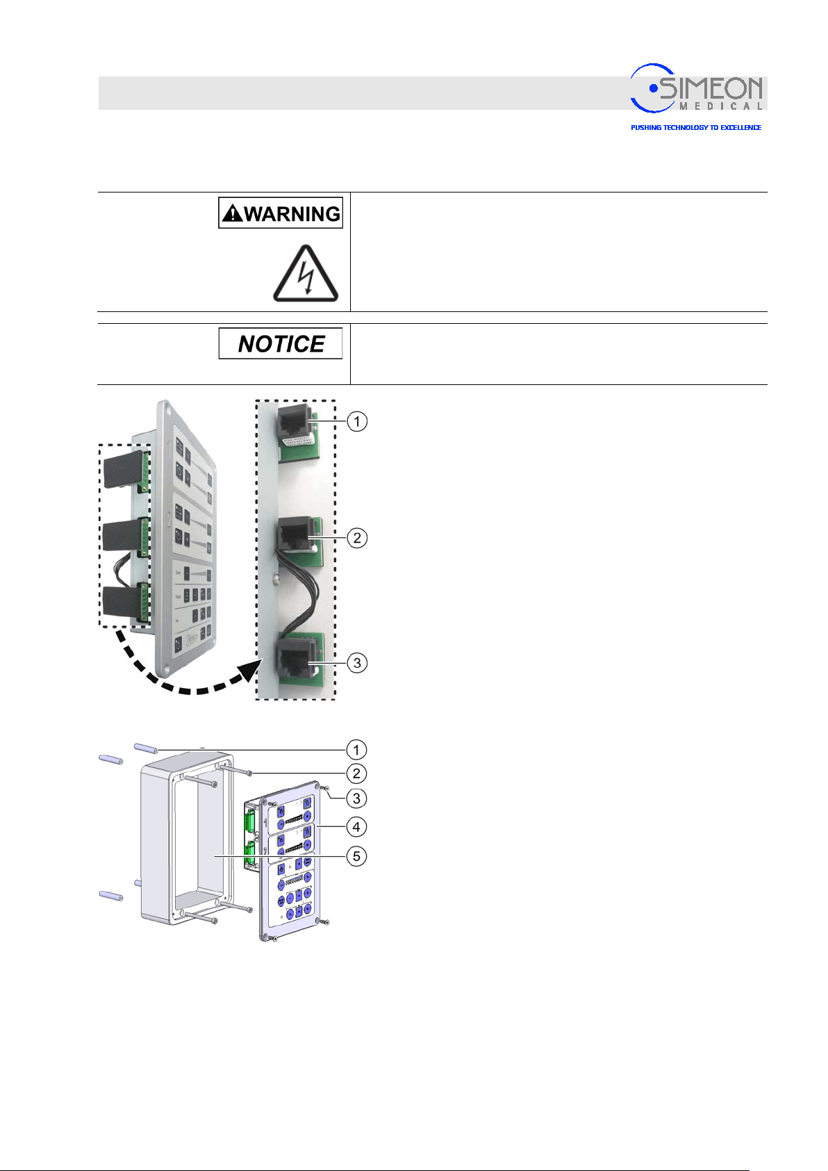
Pull the patch cable from the Sim.INTERFACE and/or
from power supply of light 1 at the wall controls’
installation point and plug into the RJ45 socket (1) of
the light.
Note: If more than one light is connected, then plug the
patch cable of the other lights into their RJ45 sockets (2).
The CAN connection which is not allocated to any light (3)
remains empty.
Surface mounting
Fasten the housing (5, illustration similar) to the base
with four screws (2) and, if necessary, distance
sleeves (1) so that the connection cables (RJ45) end
in the housing. Borehole spacing: 80 x 210 mm
Connect connection cables to the correct RJ45
socket; see above.
Fasten the wall control unit (4) to the housing with
four countersunk screws (3).
V. 1.7 56
Page 57
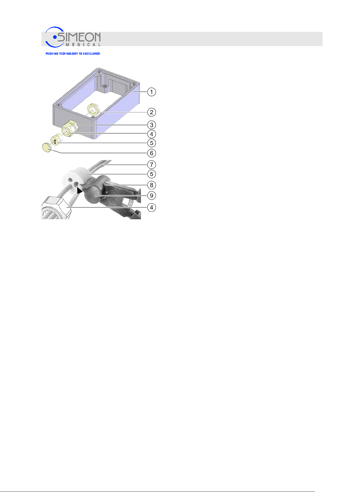
Installation Instructions Surgical LightingSim.LED 450/500/700/5000/7000 SC/MC
Mounting
If the cables are run to the housing externally, they can be
run to the housing through the cable feedthrough (3):
Unscrew the nut (4) and remove the cover (6).
Tighten counter nut (3).
Place nut (4) back on.
First, run the cable with the RJ45 plugs into the
housing (1) without strain relief (5).
Unscrew nut (4) of cable feedthrough (3) and slide it
a bit away from the housing (1) on the cable.
Open pliers (8).
Insert cable (7) between nut (4) and cable feedthrough
(3) into the large opening (9) in the pliers (8).
Close pliers (8) and plug their tip into the feedthrough
intended for the cable (see arrow).
Open pliers (8) wide enough for the cable to be pushed
into the feedthrough of the strain relief (5).
Push cable into the feedthrough of the strain relief (5),
see arrow.
Slide strain relief (5) on the cable into the cable
feedthrough (3).
Guide nut (4) back and tighten it until the strain relief is
active.
V. 1.7 57
Page 58
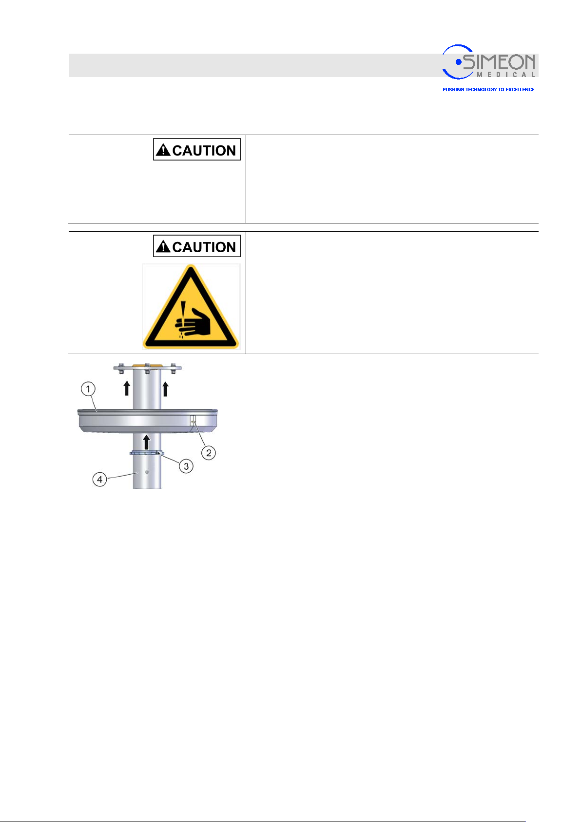
Installation Instructions Surgical LightingSim.LED 450/500/700/5000/7000 SC/MC
Mounting
4.1.15 Mounting canopy to ceiling tube
Danger of injury from falling parts!
Since mounting the arms requires overhead work, injuries can be
caused by parts falling from above.
Wear a protective helmet.
Wear safety boots.
Risk of injury due to pinching!
Multiple parts must be assembled together or mounted onto one
another. As a result, injuries may occur due to pinching.
Proceed cautiously during as s em bl y.
Wear safety boots
The figure shows the canopy on a round ceiling tube.
The Sim.FLEX system's canopy has a larger central aperture of 200
mm and is mounted onto the ceiling tube cover.
Attach retaining ring (3) to ceiling tube (4).
Mount the two half-shells of the canopy (2).
Attach silicone seal (1).
Slide canopy upwards and fasten it with retaining ring (3) (Torx
TX20).
V. 1.7 58
Page 59
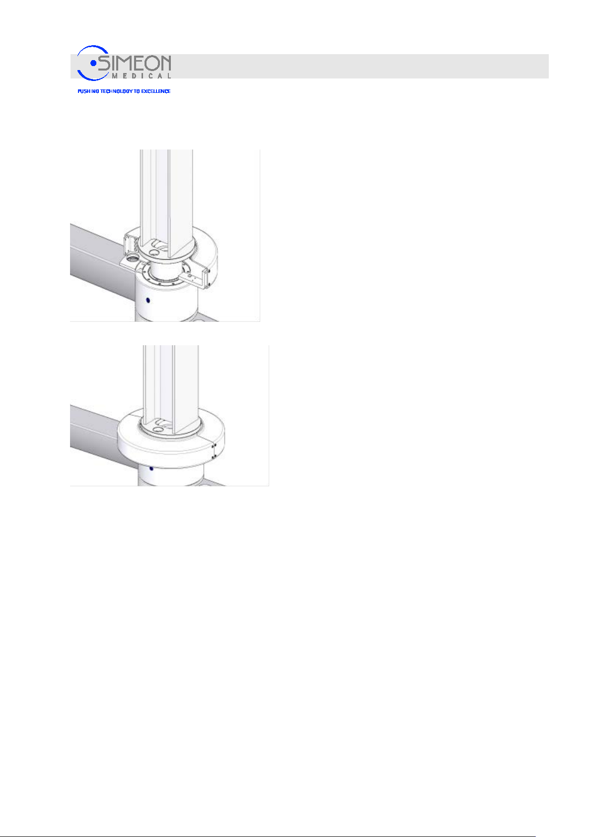
Installation Instructions Surgical LightingSim.LED 450/500/700/5000/7000 SC/MC
Mounting
4.1.16 Mount rotating canopy to Sim.Flex extension arm and normal central axis
Secure on the first half-shell of the rotating canopy with
two Allen screws.
Insert the cable for the central axis upwards through the
ceiling tube, and connect it professionally with the power
supply unit that is mounted to the ceiling tube and
assigned to the respective lights.
Place the cable around the ceiling tube in three
windings to ensure enough reserve cabling for the
extension arm's rotational range. Choose the cables’
direction of rotation so that they cannot be damaged
when the extension arm is rotated between the stop
position!
Secure the rotating canopy's second half-shell (7) to the
bracket and the first half-shell, using two Phillips head
screws (6) in each case.
V. 1.7 59
Page 60
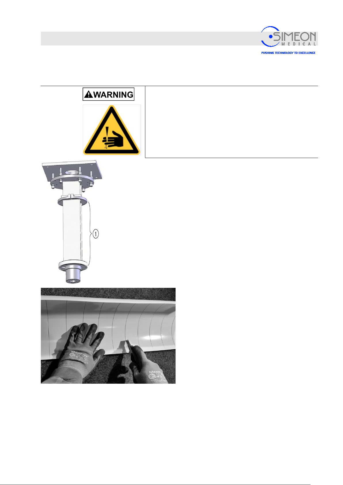
Installation Instructions Surgical LightingSim.LED 450/500/700/5000/7000 SC/MC
Mounting
4.1.17 Mounting the Sim.FLEX ceiling tube cover
Risk of fatal cutting and pinching injuri es !
Skin and body parts could be pinched during mounting of the
components. This could cause anything from cutting injuries to
death.
Mount with at least 2 trained and authorised technicians!
Wear safety boots
Mounting the Sim.FLEX ceiling tube cover
Measure the distance (1) between the holding flange
(top) and the silicone retaining ring (below).
Cut the appropriate segment for the ceiling tube
cover in such a manner that the end reaches inside
the canopy.
Accurately cut the 2 halves of the ceiling tube cover
against this segment.
V. 1.7 60
Page 61
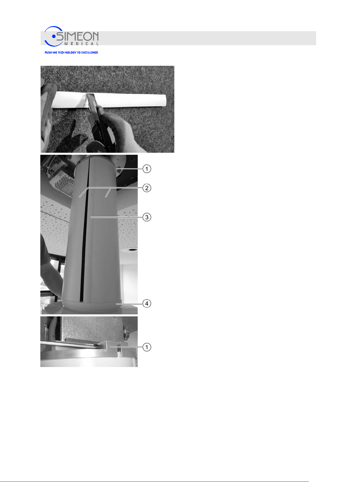
Installation Instructions Surgical LightingSim.LED 450/500/700/5000/7000 SC/MC
Mounting
Cut the closing strips of the ceiling tube cover to
the appropriate length. Two strips are required.
Insert both halves (2) of the ceiling tube cover
into the groove of the holding flange (1) above.
Insert both halves (2) of the ceiling tube cover
into the groove of the silicone retaining ring (4)
below.
Attach both closing strips.
Using a hexagon spanner, fix the holding flange
(1) in such a manner that the ceiling tube cover
is clamped but not deformed.
V. 1.7 61
Page 62
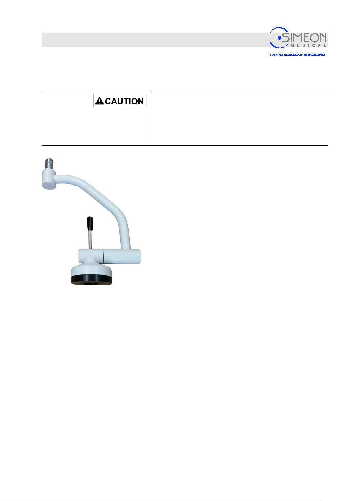
Installation Instructions Surgical LightingSim.LED 450/500/700/5000/7000 SC/MC
Mounting
4.2 Connecting the Sim.CAM HD Touch on separate extension arm
4.2.1 Mount Sim.CAM HD TOUCH camera mount onto spring arm
Danger of injury from falling parts!
Since mounting the arms requires overhead work, injuries can be
caused by parts falling from above.
Wear a protective helmet.
Wear safety boots.
Camera mount with cardanic
The cardanic for the camera mount is mounted the same way
as the cardanic for the light head,
Mounting the light heads onto the spring arm
V. 1.7 62
Page 63
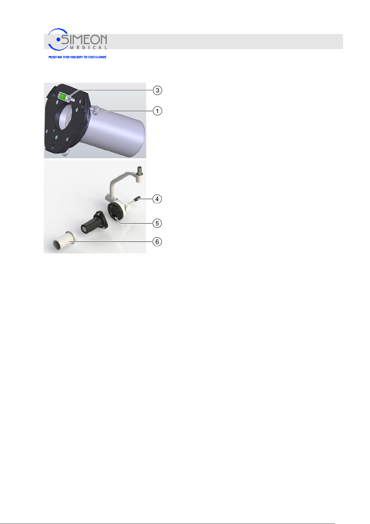
Installation Instructions Surgical LightingSim.LED 450/500/700/5000/7000 SC/MC
4.2.2 Mounting the Sim.CAM HD TOUCH onto the camera mount
Disconnect the power suppl y.
Do not touch the sub-D plug (3) in order to protect
from electrostatic discharge!
Plug the D-sub connector (3) found on the rear of the
camera unit into the socket (5) on the camera mount. In
doing so, press in the entire unit firmly and uniform l y.
Tighten the camera unit with the knurled screws (1). To do
so, turn the knurled screws in a clockwise direction. When
the knurled screws have been tightened, the position of
the unit must be checked by uniformly pressing on it once
again.
Slide the sterilisable handle (6) onto the camera unit and
turn until the safety snaps audibly into position.
Mounting
The camera unit is ready to use.
Unsterile positioning may be performed using the
handle (4) on the back side of the bracket, while
sterile positioning can be performed using the
sterilisable handle (6). Changing the sterilisable
handle,Sim.LED Instructions for Use.
Switch on the power supply once again.
V. 1.7 63
Page 64
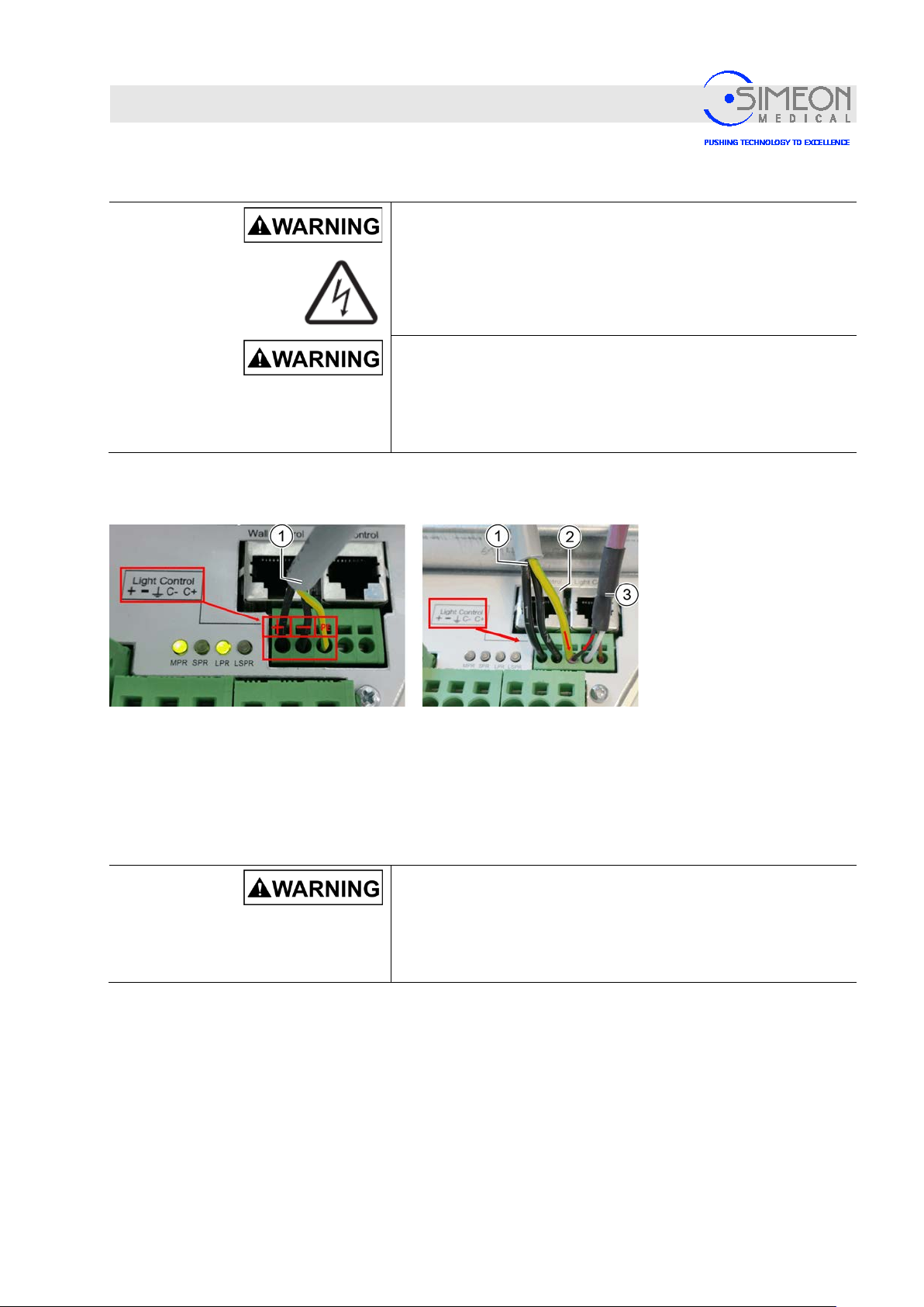
Installation Instructions Surgical LightingSim.LED 450/500/700/5000/7000 SC/MC
1: + 2:
-
GNYE:
PE
Mounting
4.2.3 Connecting the Sim.CAM HD TOUCH
Connecting the power supply , S im.CAM HD Touch in light head
Danger of electric shock!
The on-site supply line must be disconnected from the mains on
site before further work may be performed! The supply line must
be secured to prevent reconnection.
Damage or destruction from overvoltage!
The contract unit of the HD Touch may exclusively be
connected and operated with 28 V DC at the specified “Light
Control” of the terminal of the switching power supply. A
100-240 V connection will immediately destroy the device!
Connect the power supply
cable (1) of the camera's
control unit to the power
supply, as shown at left:
Connect the control lines (3) of the light to the right. In this case, the PE terminal must be used for
control lines (3, grounding shield) and camera control unit (1, GNYE) together, as shown in the photo
on the right.
If wall controls are present, they are to be connected to the RJ45 socket,
“Mounting and connecting the power supply unit for surgical lights to the ceiling tube“, page 49.
Connecting the power supply , S im.CAM HD Touch on separate arm
Damage or destruction due to incorrect connection!
The control device of the HD Touch may only be connected
and operated with the switching power supply which is also
connected to the associated ligh t with video camera and
corresponding video line from the central axis!
V. 1.7 64
Page 65
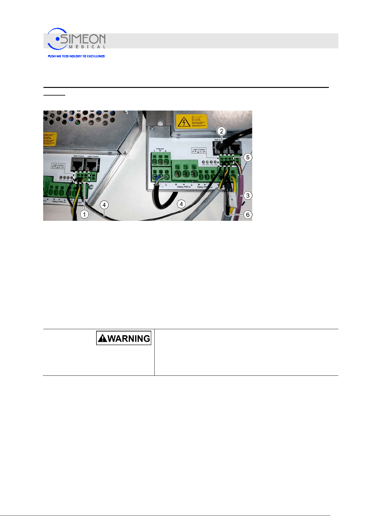
Installation Instructions Surgical LightingSim.LED 450/500/700/5000/7000 SC/MC
Mounting
The Sim.CAM HD Touch on separate arm is always to be connected to a separate switching power
supply!
Connect power supply
for
Sim.CAM HD TOUCH
to power supply 1 (1, on
the left of the photo).
Connect power supply
for HD TOUCH control
unit to power supply 2
(5, on the right of the
photo).
Connect the control lines (3) of the light to the right. In this case, the PE terminal must be used for
control lines (3, grounding shield) and HD TOUCH control unit (5, GNYE) together, as shown in the
photo on the right.
Connect power supply for the light to power supply 2 (6, on the right of the photo).
Connect wall controls (if present) to RJ45 socket (2).
In order to avoid potential communication interference, connect the negative pole of the power
supplies of the Sim.CAM HD TOUCH (on the left of the photo) and the HD TOUCH control unit (on the
right of the photo) with a black cable (4). This cable may be a maximum of 1.5 m long. This will suffice
on the ceiling tube; with other mounting types, ensure that the two power supplies are suitably close to
one another!
Damage or destruction due to incorrect connection!
The control device of the HD Touch may only be connected
and operated with the switching power supply which is also
connected to the associated ligh t with video camera and
corresponding video line from the central axis!
V. 1.7 65
Page 66
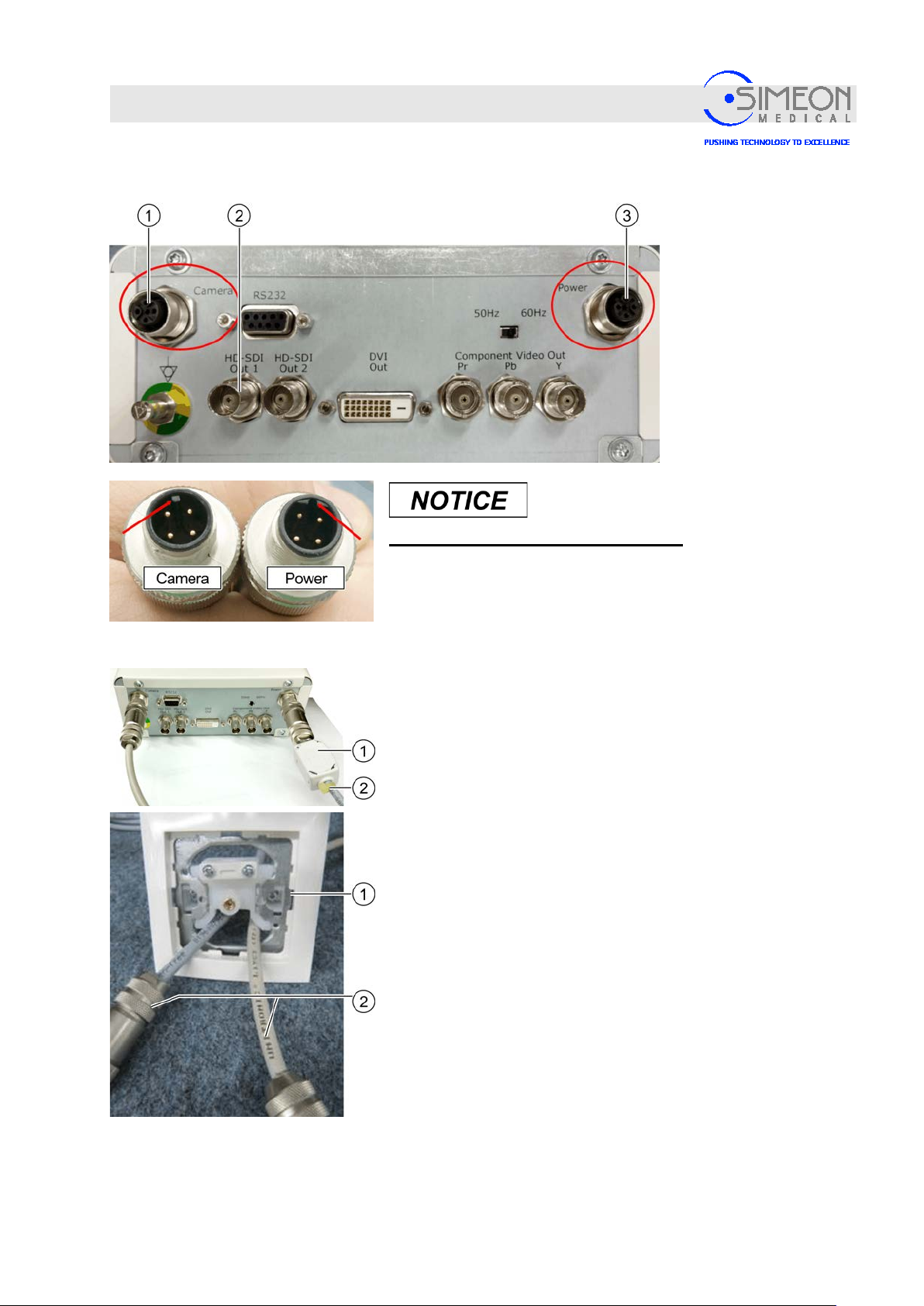
Installation Instructions Surgical LightingSim.LED 450/500/700/5000/7000 SC/MC
Mounting
Connecting the HD Touch control unit
Avoid confusing the cable connections!
Connect the power cable to the power socket (3).
Connect the camera cable to the camera socket (1).
Connect the video output signal to HD-SDI Out (1 or 2) or DVI
Out.
Mount the ferrite core (1) to the power cable and secure with a
cable tie (2).
Flush mounting the cable
Pull the cable (2) through the cable cover (1).
Screw on the cable cover's (1) lid.
V. 1.7 66
Page 67
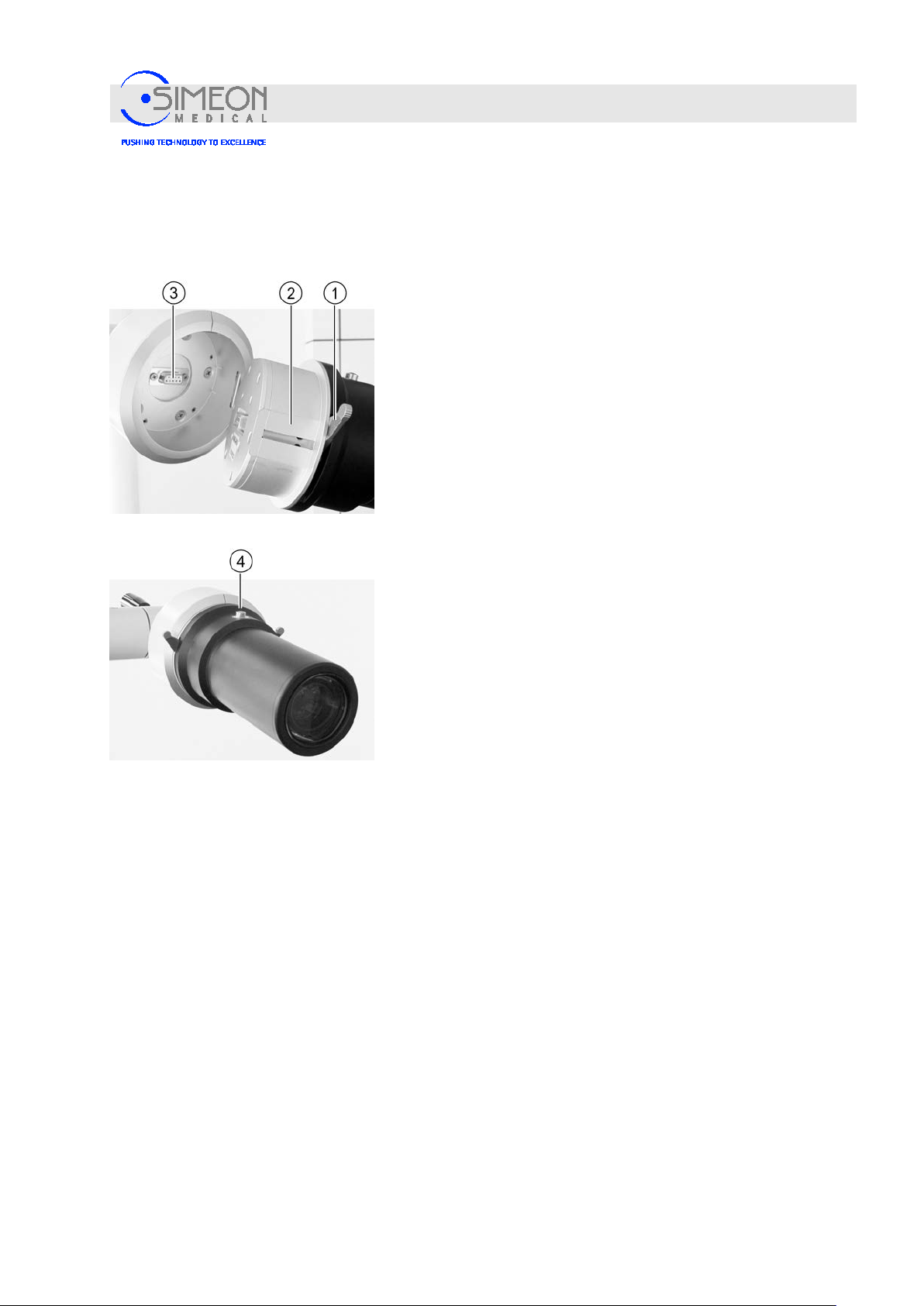
Installation Instructions Surgical LightingSim.LED 450/500/700/5000/7000 SC/MC
Mounting
4.3 Mounting the Sim.CAM HD (Sim.LED 5000/7000 only)
The camera is an optional accessory and can be installed on the light head of ceiling variants in place of the
sterile handle or the handle unit.
Camera on a separate arm
Disconnect the power suppl y.
Ensure that both latching tabs (1) are fully open. The red
surfaces must be visible!
The connector base (2) is encoded. A turning out of
position is not possible.
Slide the camera module into the socket (3).
The camera must sit fully in the socket.
Lock module
Press down on both latching tabs (1) until the red markings
can no longer be seen.
Mount sterilisable handle
Slide the sterile handle onto the handle unit and turn until the
release button (4) snaps audibly into position.
Switch on the power supply at the control unit.
The camera is ready for operation.
Remove sterilisable handle again if necessary
Press release button (4).
Pull off sterilisable handle.
V. 1.7 67
Page 68
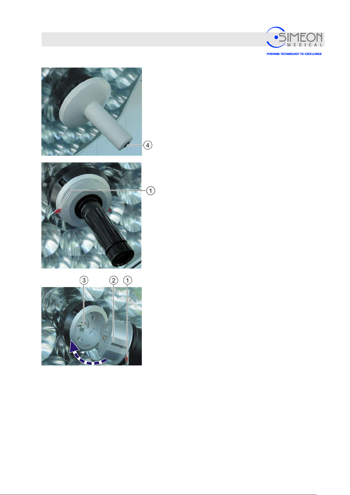
Installation Instructions Surgical LightingSim.LED 450/500/700/5000/7000 SC/MC
Mounting
Camera on the lighting handle
Remove sterilisable handle. To do so, press the release
button (4).
Pull off sterilisable handle.
Inspect the sterile handle for wear and damage, dispose of
and replace it if necessary.
Hold handle firmly.
Open latching tabs (1). The red surfaces must be visible!
Remove the handle unit.
Install the camera on the lighting handle identically as
with the camera on a separate arm,
“Camera on a separate arm“, page67.
V. 1.7 68
Page 69
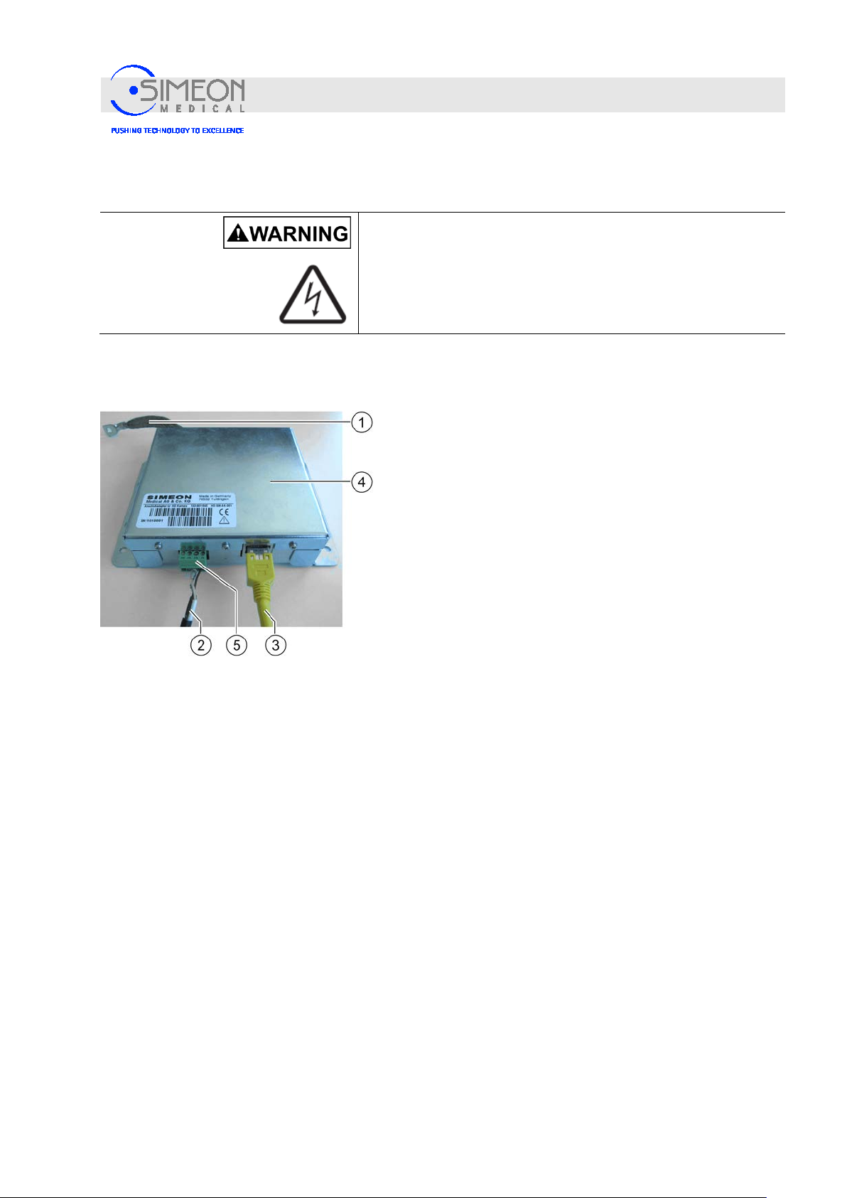
Installation Instructions Surgical LightingSim.LED 450/500/700/5000/7000 SC/MC
4.3.1 Sim.CAM HD terminal board
Mounting
The terminal board for the Sim.CAM HD is normally mounted in the ceiling flange. If the terminal boar d is
found outside of the laminar flow ceiling, a longer earth wire (braided mains cable, minimum cross-section
10 mm²) must be used.
Danger of electric shock!
The on-site supply line must be disconnected fr o m the
mains on site before further work may be performed! The
supply line must be secured to prevent reconnection.
Electrically connect the metal housing of the terminal
board (4) with the metal housing of the ceiling flange, in
an HF-compatible manner. To do so, use the enclosed,
flexible braided mains cable (1). The braided mains
cable must have a minimum cross-section of 10 mm².
Connect the yellow 20 m patch cable (3) (video input
signal), to the control unit for the Sim.CAM HD.
Connect the other end of the patch cable (3) to the
terminal board (as shown in the image).
Plug the cable with the Phoenix connector (5) into the
terminal board and plug the other end (S-video
connector) into the S-video socket in the central axis.
The plug-in connection (2) and S-video socket of the
central axis must be secured against tensile strain!
V. 1.7 69
Page 70
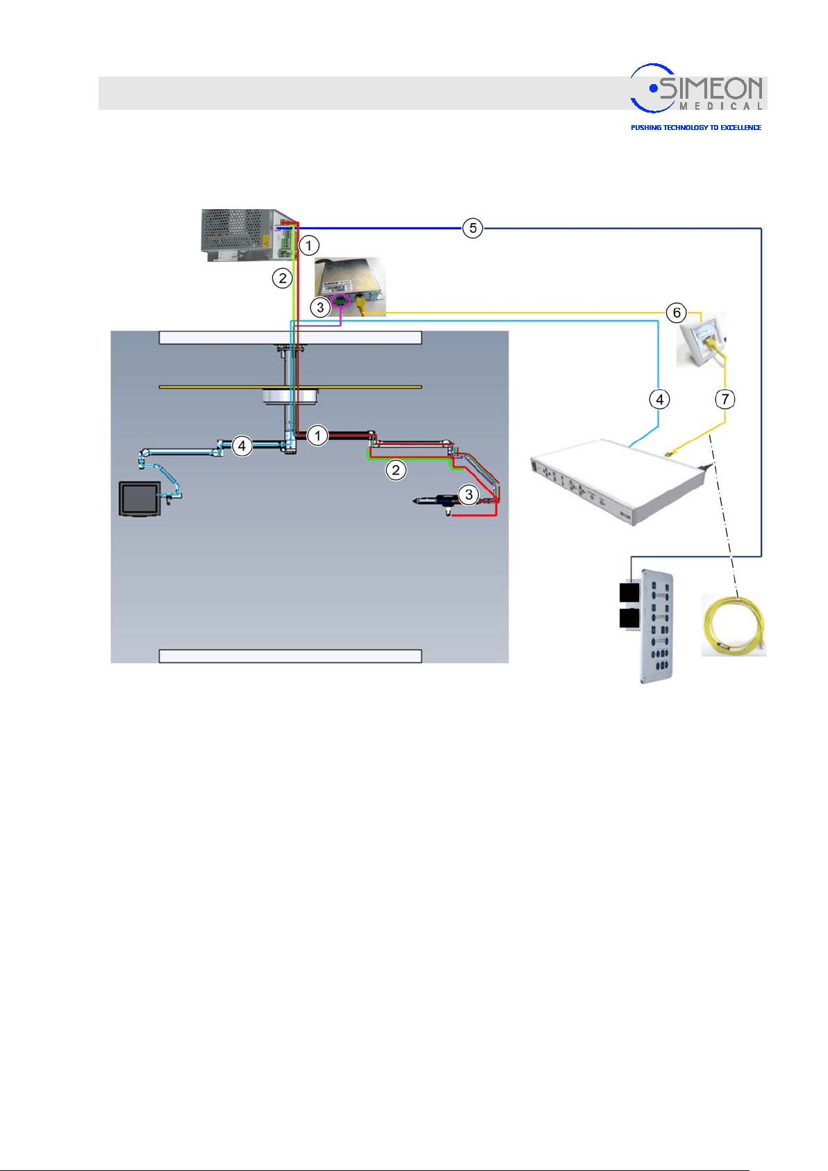
Installation Instructions Surgical LightingSim.LED 450/500/700/5000/7000 SC/MC
1
CAN connection from power supply to light / camera
2
Power supply for light
3
Video signal and control unit for Sim.CAM HD
4
HDSDI cable from the control unit's output to the monitor input
5
RJ45 patch cable between the power supply and wall controls (for wall controls)
6
20 m RJ45 patch cable between adapter and wall socket
7
5 m connecting cable between wall socket and control unit
Mounting
4.3.2 Example: Sim.CAM HD wiring diagram
V. 1.7 70
Page 71
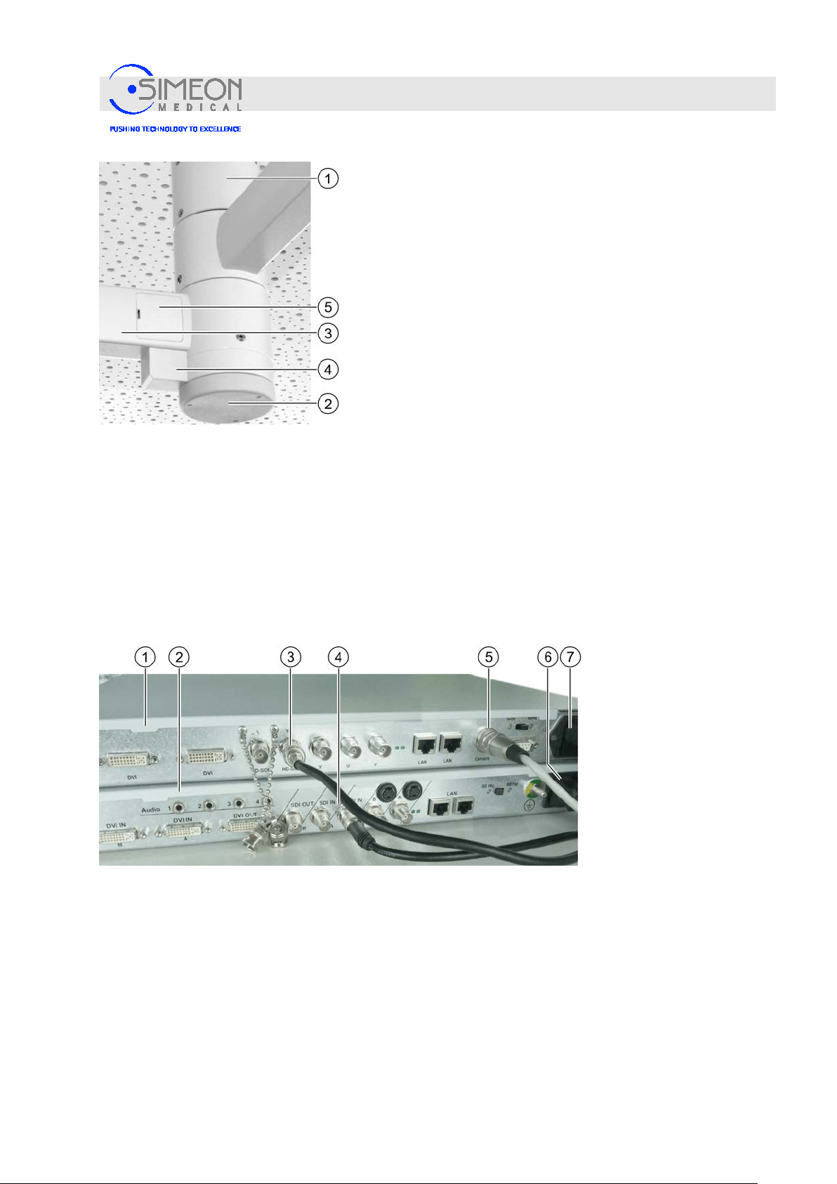
Installation Instructions Surgical LightingSim.LED 450/500/700/5000/7000 SC/MC
Mounting
Remove cap (2).
Connect video cable in the central axis with the blac k
connection cable. Pull cable through ceiling tube and
extension arm.
The plug-in connection and S-video socket of the central axis
must be secured against tensile strain!
Remove cover (5).
Guide the cables through the extension arm (3) without
placing them under mechanical strain, so they are not
damaged during rotational movement.
Push back approx. 5 cm of cable reserve into the extension
arm.
Pull video cable and then power cable through the extension
arm and spring arm,
Mount rotating canopy to Sim.Flex extension arm and
normal central axis
Connect the Sim.CAM HD according to the Instructions for
Use 100-0010175.
4.3.3 Connecting the Sim.STREAM
Use the cold lead to connect Sim.STREAM (2) to the connection (6) with the Schuko socket.
Connect BNC cable to the BNC socket (3, HD-SDI) of the HD control unit (1) and connect it with the
BNC socket (4, SDI-IN) of the Sim.STREAM (2).
Use the cold lead to connect the HD control unit (1) to the connection (7) with the Schuko socket.
V. 1.7 71
Page 72
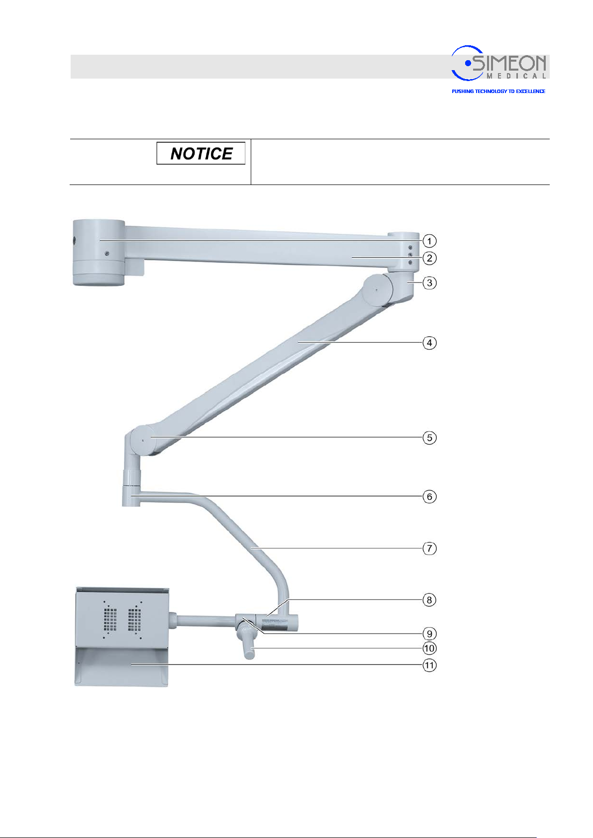
Installation Instructions Surgical LightingSim.LED 450/500/700/5000/7000 SC/MC
1
Extension arm/central axis
end
5
Spring arm joint
9
Joint on sterilisable handle
2
Extension arm
6
Cardanic pivot for spring arm
10.
Sterilisable handle
3
Spring arm joint
7
Cardanic tube
11
Monitor mount
4
Spring arm
8
Cardanic pivot for monitor
Mounting
4.4 Mounting the Sim.SCREEN monitor suspension
4.4.1 Overview
Before mounting, check that the stop pieces at the central
axis are correctly positioned.
“Mounting the round central axis“, page33.
V. 1.7 72
Page 73
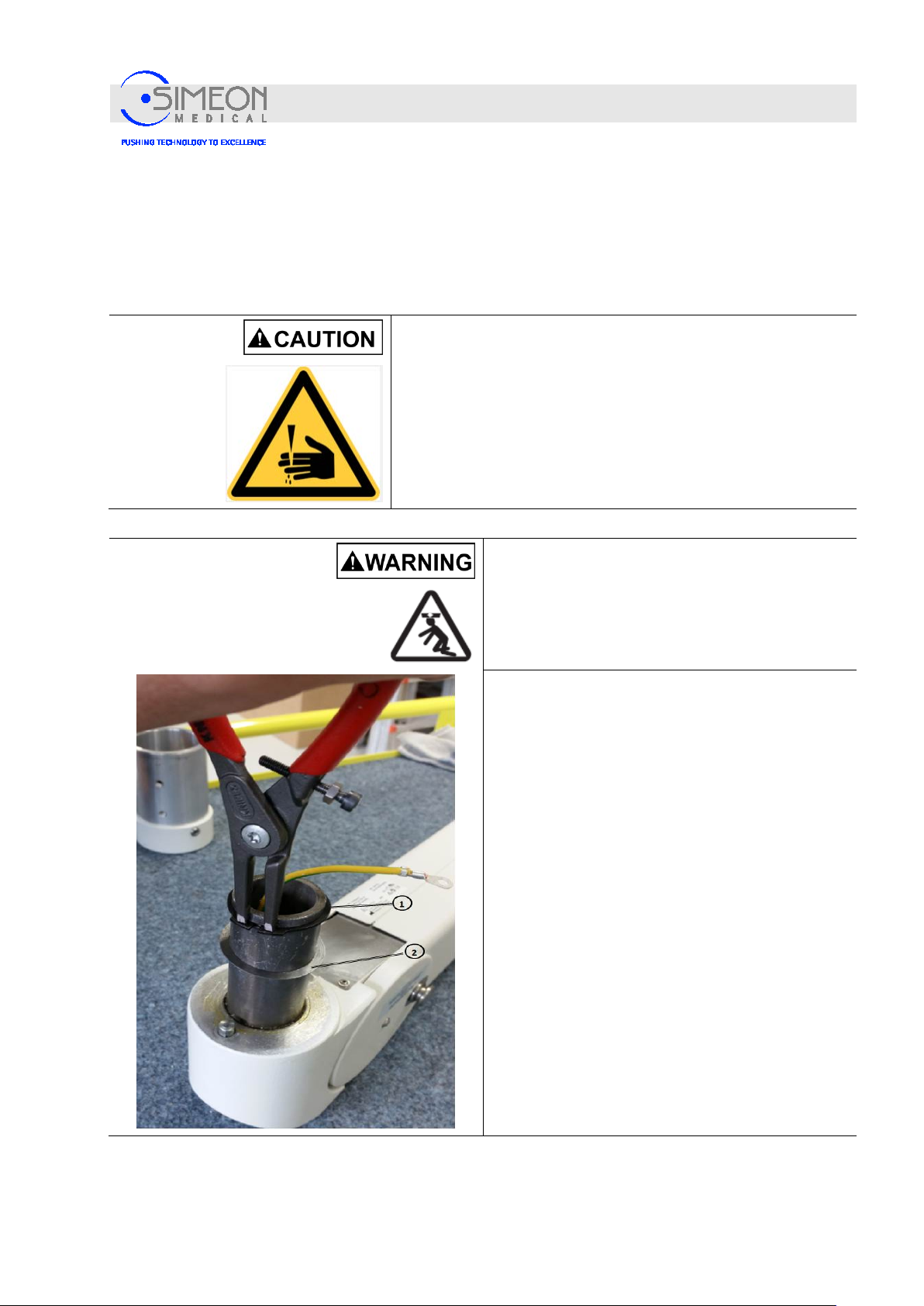
Installation Instructions Surgical LightingSim.LED 450/500/700/5000/7000 SC/MC
Mounting
4.4.2 Mounting the extension arm
“Mounting the round central axis“, page33.
4.4.3 Mounting adapter to AC3000/OSP spring arm
The adapter for the AC3000/OSP Ondal spring arm is mounted before the AC3000/OSP spring arm is
mounted to the central axis.
Danger of injury from falling parts!
Since mounting the arms requires overhead work, injuries can be
caused by parts falling from above.
Wear a protective helmet.
Wear safety boots.
Wear protective gloves.
Risk of injury due to a collapsing spring arm!
The locking ring may not be overstretched and
must properly snap into the groove when mounted!
Otherwise, injuries may be caused by falling parts!
Only mount locking ring once.
Dismantle locking ring (1), washer (2) and
protective sleeve according to manufacturer’s
assembly instructions.
V. 1.7 73
Page 74
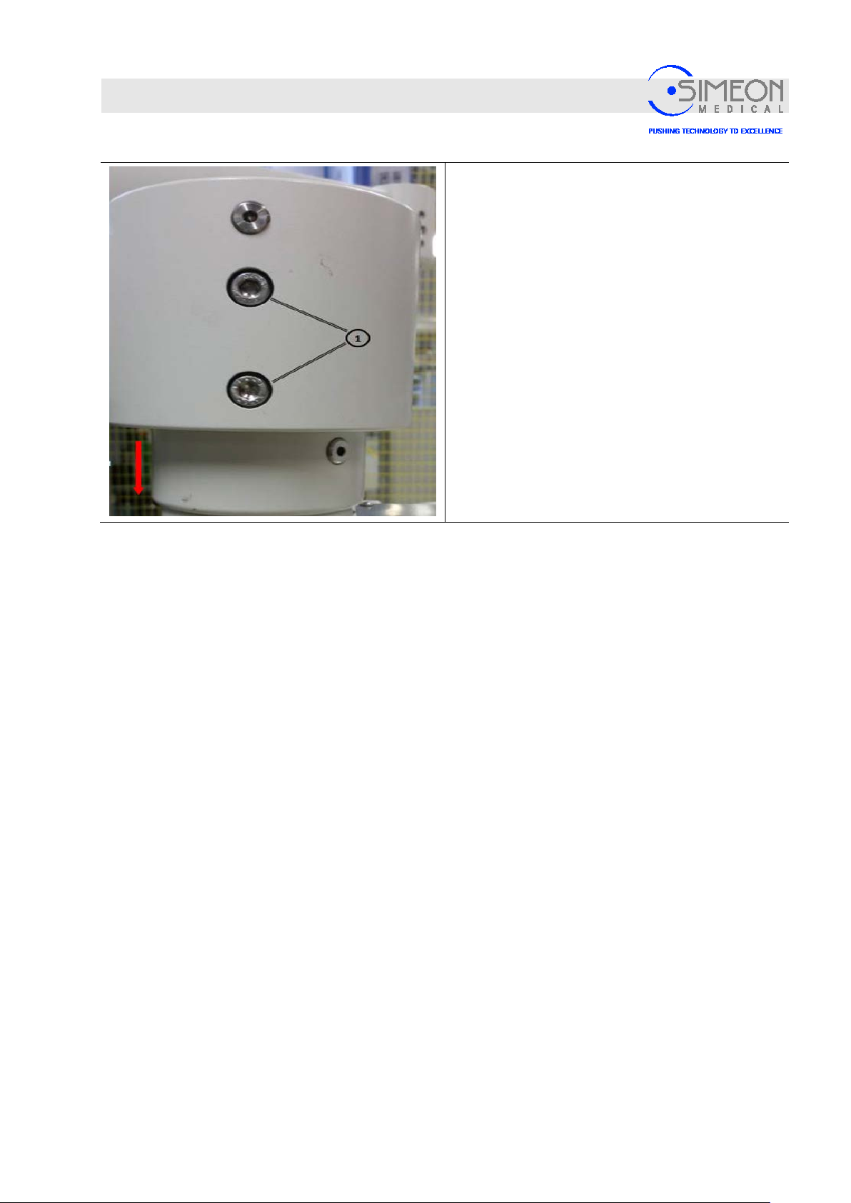
Installation Instructions Surgical LightingSim.LED 450/500/700/5000/7000 SC/MC
Mounting
In this variant, the adapter is delivered mounted on
the extension arm or the extension arm.
Put your hand under the opening in the socket
and secure it to prevent it from falling.
Loosen the two M8 cylinder screws (1) on
extension arm.
Remove the brake screw (2) from the threaded
hole.
Remove adapter downwards from the
extension arm (see red arrow)
V. 1.7 74
Page 75
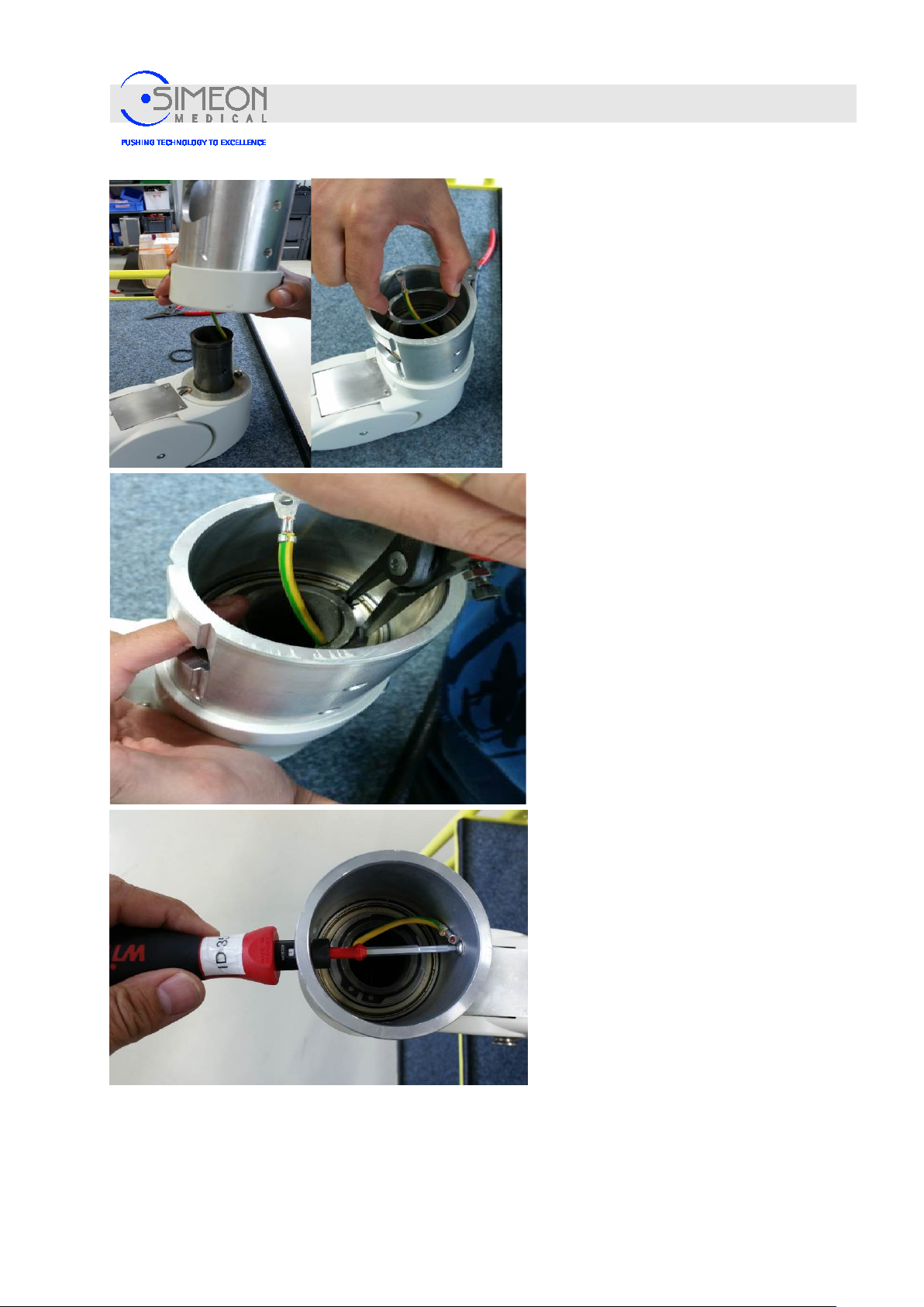
Installation Instructions Surgical LightingSim.LED 450/500/700/5000/7000 SC/MC
Mounting
Insert the socket (5) on the pivot (9) of
the spring arm (4) and make sure that
the grounding conductor is not pinched
(photo at left)
Mount the washer (7) - the pivot groove
for the locking ring (6) remains free in
the process (photo at right)
Mount locking ring (6) according to
manufacturer’s specifications (similar to
photo at left).
Mount grounding conductor to adapter
with enclosed M4 screw.
2 Nm torque.
V. 1.7 75
Page 76
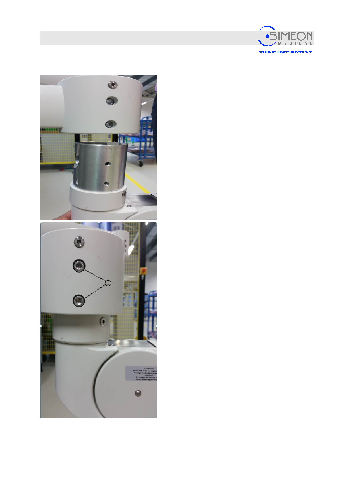
Installation Instructions Surgical LightingSim.LED 450/500/700/5000/7000 SC/MC
Mounting
4.4.4 Mounting the AC3000/OSP spring arm
Align the spring arm with adapter vertically and
horizontally and place it in the extension arm as far
as it will go so that the threaded holes for the
cylinder screws are aligned with the holes in the
extension arm.
Mount the spring arm with both cylinder screws (1)
M8.
16 Nm torque.
The cable insertion, final assembly and settings
are to be conducted according to the installation
instructions of the company Ondal Medical
Systems OndaSpace.
V. 1.7 76
Page 77
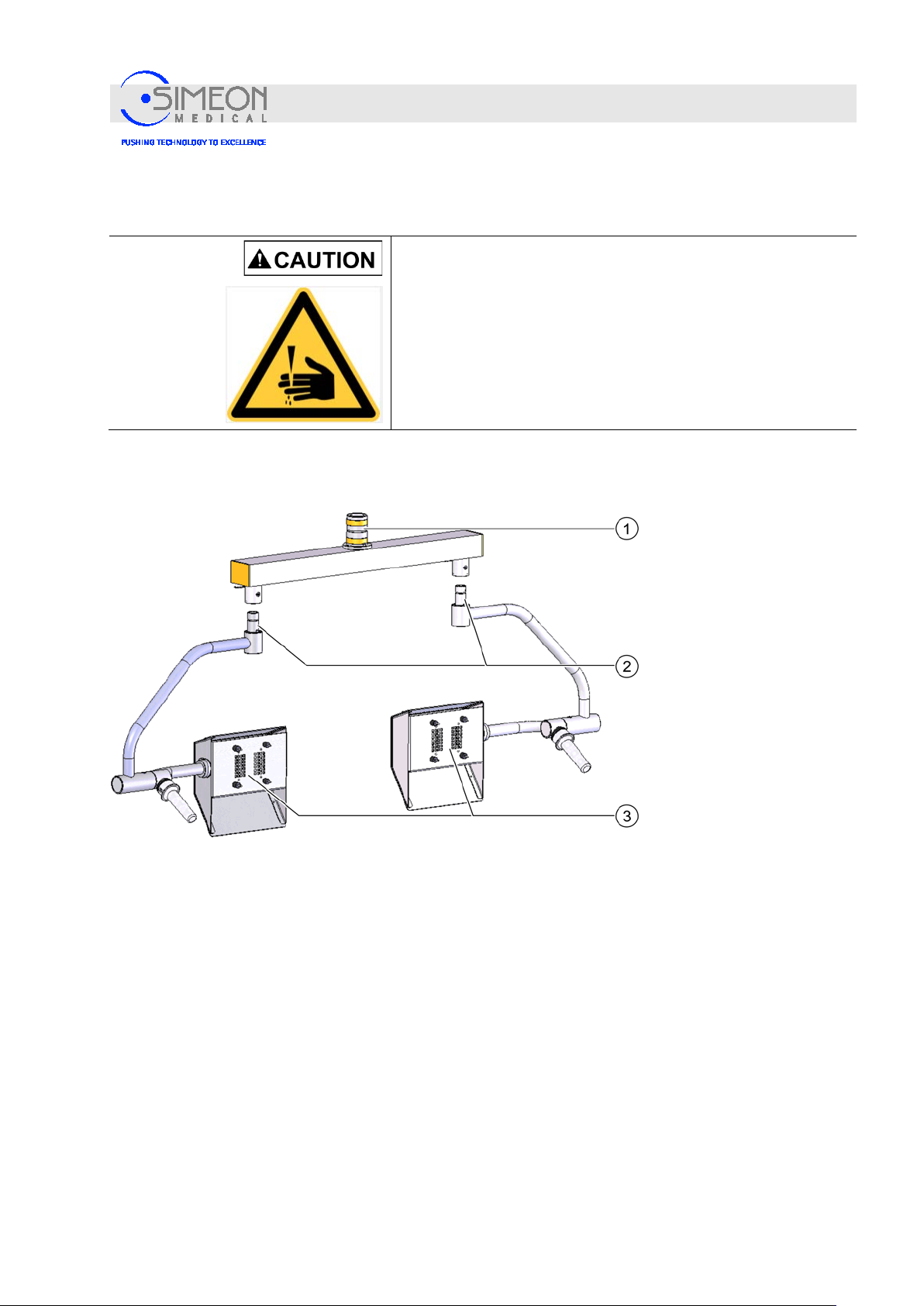
Installation Instructions Surgical LightingSim.LED 450/500/700/5000/7000 SC/MC
Mounting
4.4.5 Mounting the Sim.SCREEN monitor mount to the AC3000/OSP spring arm
Danger of injury from falling parts!
Since mounting the arms requires overhead work, injuries can be
caused by parts falling from above.
Wear a protective helmet.
Wear protective gloves.
The Sim.SCREEN dual monitor mount (1) is mounted according to the installation instructions of the
company Ondal Medical Systems OndaSpace.
When mounting a dual monitor bridge, two different interfaces must be installed:
− Monitor cardanic at the bridge (2): Mounting is similar to the mounting of the light head to the spring
arm, but without a turning connector,
Mounting the extension arm
V. 1.7 77
Page 78
Installation Instructions Surgical LightingSim.LED 450/500/700/5000/7000 SC/MC
Mounting
4.4.6 Sim.SCREEN monitor mount: Positioning the lateral stop pieces
An extension arm for a monitor mount can be provided for at the lowermost or uppermost position of the
central axis. Since the monitor is connected in wired form, this extension arm must be secured against
overtwisting using at least one stop piece at each joint, to prevent the overextension and breaking of the
cables.
Danger of electric shock!
If a stop piece is forgotten during assembly of a monitor mount,
this may result in a short circuit or, in an extreme case, in electric
shock during operation of the monitor.
Danger of injury from falling parts!
Since mounting the arms requires overhead work, injuries can be
caused by parts falling from above.
Wear a protective helmet.
Wear protective gloves.
V. 1.7 78
Page 79
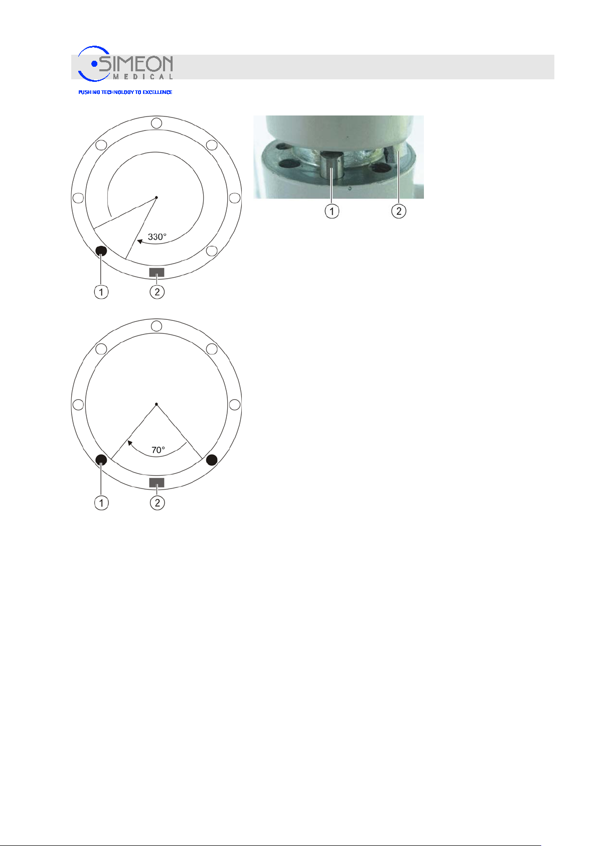
Installation Instructions Surgical LightingSim.LED 450/500/700/5000/7000 SC/MC
Mounting
The stop piece (2) is firmly mounted at the spring arm joint. The
stop pins (1) may be variably used in the monitor mount. A stop pin
is an integral component of the mounting materials that are
included with every monitor mount “mou nti ng materials“, page
84.
Disconnect the power suppl y.
Place the stop pin (1) on the desired position.
Note: The stop pin must be inserted entirely into the opening;
otherwise, the attachment at the spring arm will be problematic.
When using only one stop pin, the swing equals approx.
330°.
With two stop pins, the movement radius for the monitor
mount can be limited; the minimum angle is 45°.
When turning the extension arm, check whether the desired
range of rotation has been achieved. Otherwise, adjust the
stops.
V. 1.7 79
Page 80
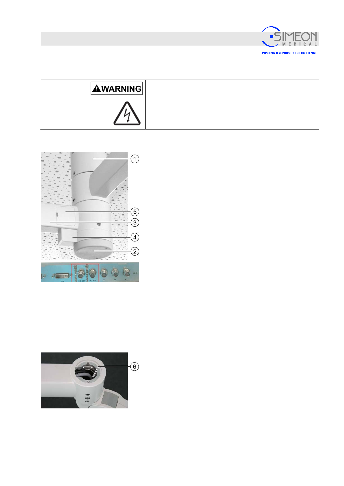
Installation Instructions Surgical LightingSim.LED 450/500/700/5000/7000 SC/MC
Mounting
4.4.7 Connect monitor suspension cabling
Round ceiling tube: Cabling to spring arm
Danger of electric shock!
Chafed cables may produce an electric shock! Lay the cabling
without placing it under mechanical strain and use a bending
radius large enough to avoid damage during canopy rotation.
Only use original parts from the manufacturer!
Remove the cap (2).
Pull cable with video output signal through ceiling tube (1)
and extension arm (3, 4): Black video cable for Sim.CAM SD;
cable for HD control unit for Sim.CAM HD.
Remove cover (5).
Pull cable through ceiling tube and extension arm. Guide the
cables through the extension arm without placing them under
mechanical strain, so they are not damaged during rotational
movement.
Push back approx. 5 cm of cable reserve into the extension
arm (3).
Insert the cables carefully into the joint (6) of the spring arm.
Insert the cabling without placing it under mechanical strain
and use a bending radius large enough to avoid damage
during rotational movements.
Note: If the cable plugs do not fit into the opening between the
extension arm and the spring arm adapter, undo the installation
socket and remove cables from the extension arm.
V. 1.7 80
Page 81
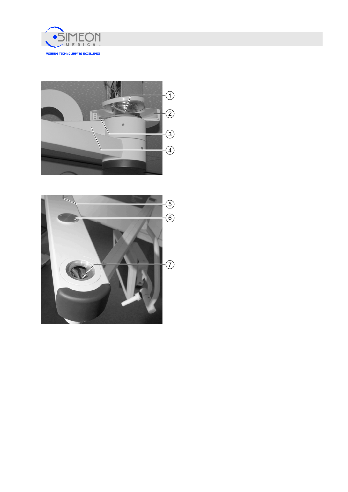
Installation Instructions Surgical LightingSim.LED 450/500/700/5000/7000 SC/MC
Sim.FLEX ceiling tube: Cabling to spring arm
Mounting
With the rotating canopy open (2, “Mounting
canopy to ceiling tube“ , pag e 58) , wind the
cables (1) around the ceiling tube in 3 windings to
ensure enough reserve cabling for the extension
arm's rotational range.
Choose the direction of rotation so that the cable
cannot be damaged when the extension arm is
rotated form stop to stop. To do so, it must be
exposed without tensile strain in every position of
the extension arm.
Insert the cables into the aperture (3) on the
extension arm (4) and push through until the
cabling is visible at the front end of the arm.
Insert the cables carefully into the joint (7) of the
spring arm.
Insert the cabling without placing it under
mechanical strain and use a bending radius
large enough to avoid damage during rotational
movements.
Note: If the cable plugs do not fit into the opening
between the extension arm and the spring arm
adapter, undo the installation bushing and remove
cables from the extension arm.
Fit the cover (6) using 2 countersunk screws (5).
V. 1.7 81
Page 82
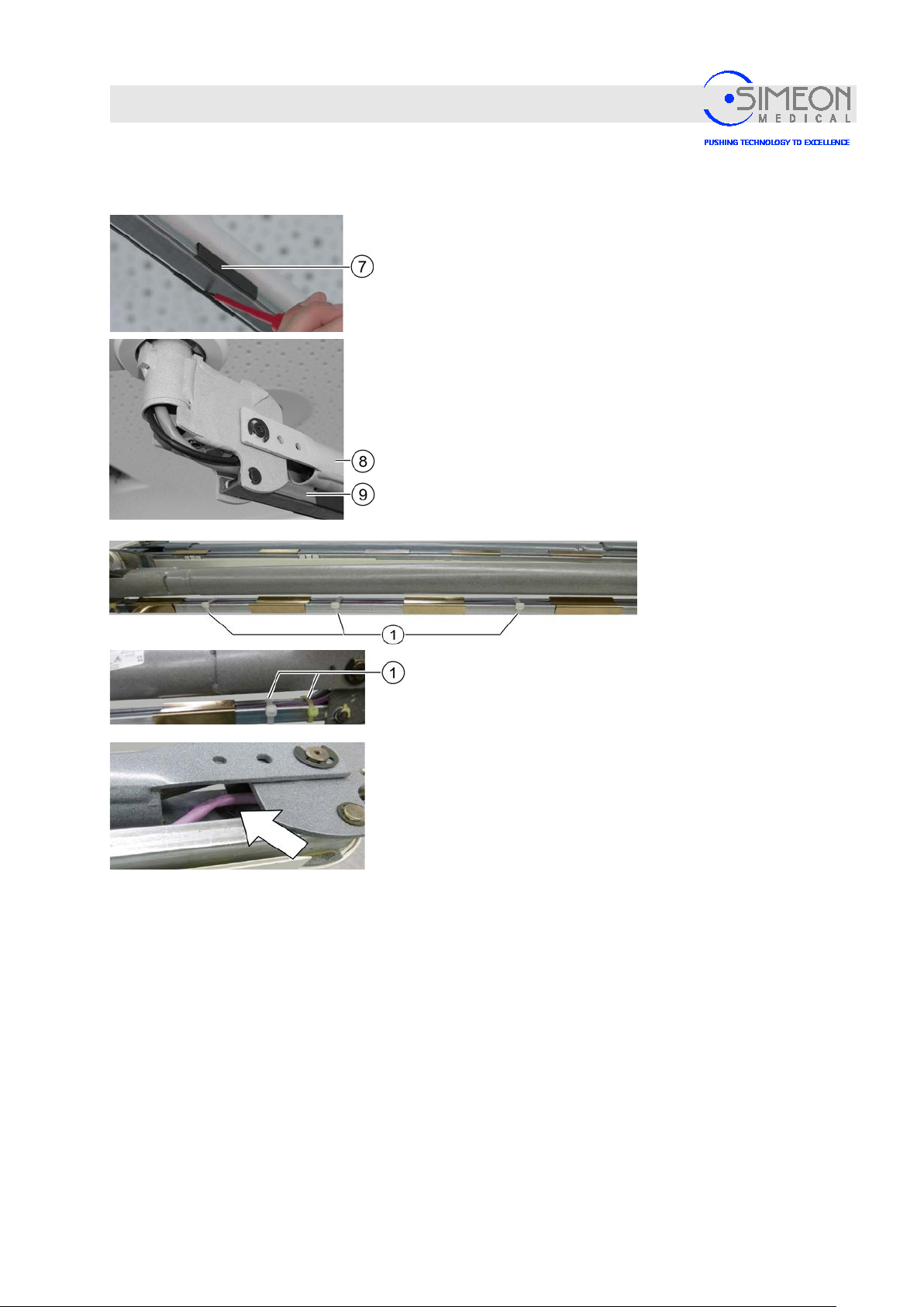
Installation Instructions Surgical LightingSim.LED 450/500/700/5000/7000 SC/MC
Mounting
Cabling from the spring arm
Carefully loosen the clamps (7) on both sides with a
screwdriver and slide upwards.
Note: The panelling for the spring arm is disassembled for
delivery.
Insert the cabling through the spring arm's (8) cable inlet
without placing it under mechanical strain, and use a
bending radius large enough to avoid damage during
rotational movements.
Note: Lay the cabling without any crossover.
Slide the clamps (9) downwards and allow to snap into
place. In the process, make sure that the cables are not
pinched.
In addition, secure the cables with cable ties (1) so that
they cannot escape from the cable inlet even when the
spring arm moves.
Note: Cables escaping from the cable inlet can be pinched
and become damaged when the spring arm moves.
A CAN cable that is damaged in this manner may result in a
malfunction, for example.
V. 1.7 82
Page 83
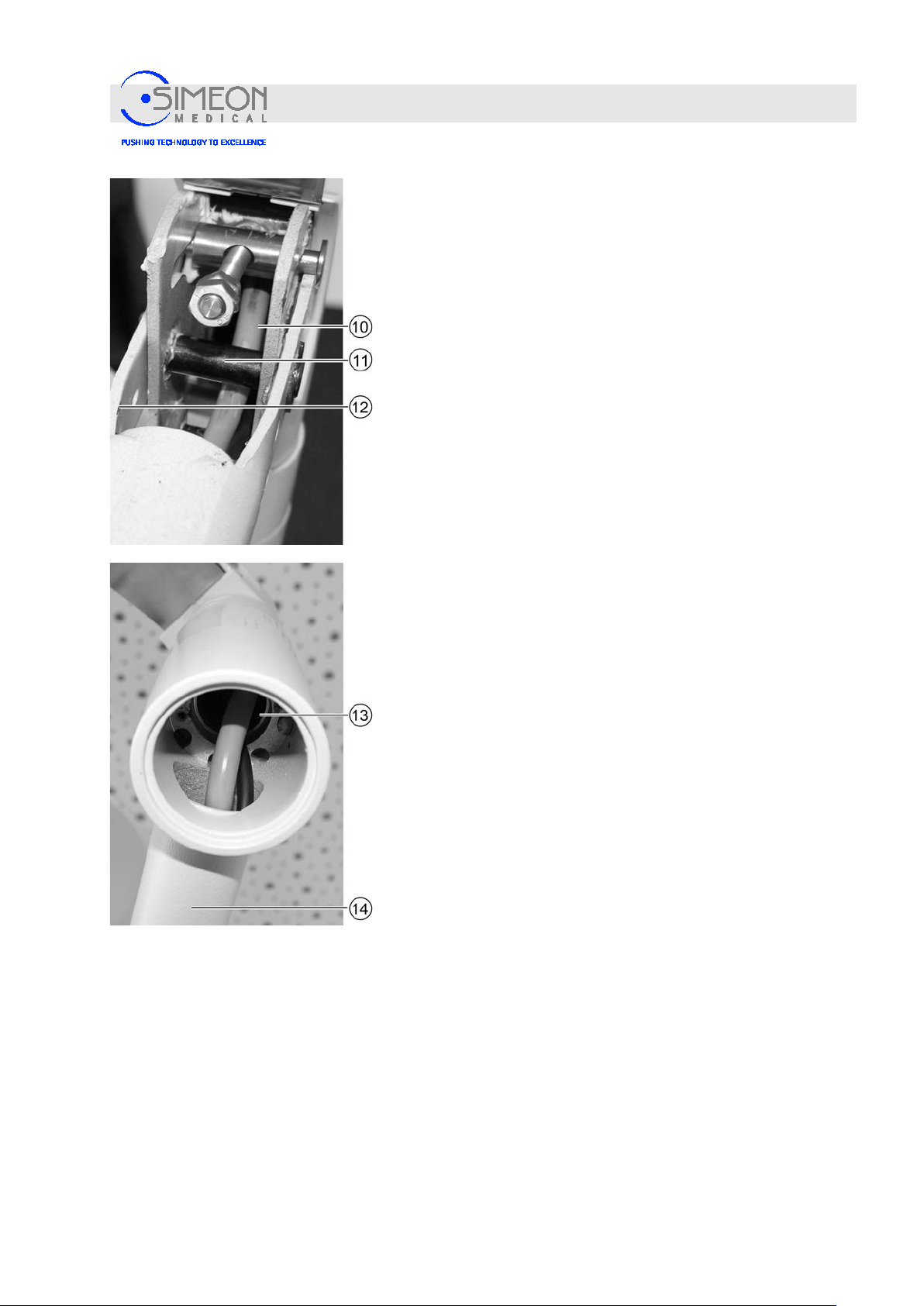
Installation Instructions Surgical LightingSim.LED 450/500/700/5000/7000 SC/MC
Mounting
Guide the cable (10) located at the spring arm's joint (12)
below the screw connection (11), downwards through the
spring arm's head, in the direction of the cardanic pivot (13,
image below).
Insert the cabling without placing it under mechanical strain
and use a bending radius large enough to avoid damage
during rotational movements.
Insert the cabling through the cardanic pivot (13) into the
cardanic tube (14) without placing it under mechanical strain,
and use a bending radius large enough to avoid damage
during rotational movements.
V. 1.7 83
Page 84
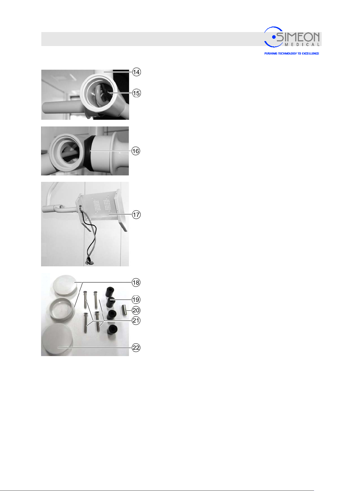
Installation Instructions Surgical LightingSim.LED 450/500/700/5000/7000 SC/MC
Mounting
Starting at the cardanic tube (14), thread the cabling through
the monitor joint (15) without placing it under mechanical
strain, and use a bending radius large enough to avoid
damage during rotational movements.
Insert the cabling through the joint at the sterilisable handle
(16) without placing it under mechanical strain, and use a
bending radius large enough to avoid damage during
rotational movements.
Carefully pull the cable at the monitor mount (17).
Mount angled mains connector (SCHURTER article 4785)
according to instructions from the company Schurter
(www.schurter.com).
Note: These mounting materials are included with every
Sim.SCREEN monitor mount:
− 2 x Kapsto covers (18) for cardanic pivots, monitor
− 1 x Kapsto cover (22) for cardanic pivots, spring arm
− 4 x mounting screws (21) long, for mounting with distance
sleeves
− 4 x distance sleeves (19)
− 1 x stop pin (20)
Mount the Kapsto cover.
V. 1.7 84
Page 85
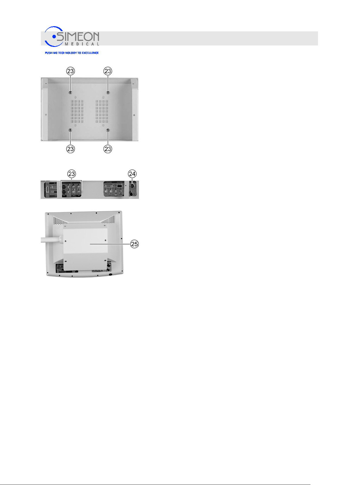
Installation Instructions Surgical LightingSim.LED 450/500/700/5000/7000 SC/MC
Mounting
Mount monitor: Screw four screws into the corresponding
threaded holes VESA100 (23) of the monitor.
If the monitor mount covers aerating slots on the monitor, the
use of distance sleeves (19, “mounting mat eria ls “, page
84) in combination with longer screws (21, „mounting
materials“, page 84) will create a distance between the
aerating slots and the monitor mount that will allow for
ventilation of the monitor.
Connect the monitor to the power supply unit and signalling
cable.
Cabling the monitor:
23: DVI in / HDMI in for HD cameras,
SVIDEO in for SD cameras
24: Power cable
Screw the cover sheet (25) onto the monitor mount, using
washers and flat head screws.
Mount the casing for the spring arm.
“Mount the spring arm shells on the spring arm (ceiling
variant only)“, page 107.
V. 1.7 85
Page 86
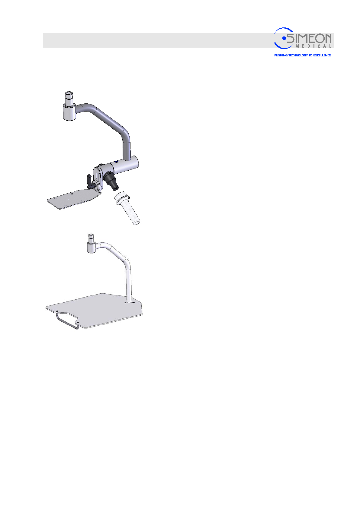
Installation Instructions Surgical LightingSim.LED 450/500/700/5000/7000 SC/MC
Mounting
4.4.8 Mount GTP8 and GTP14
Mounting is similar to the mounting of the light head to the spring
arm,
Mounting the light heads onto the spr ing arm,
but without a turning connector.
The lateral stops are adjusted as described inSim.SCREEN
monitor mount: Positioning the later a l stop piec es
Instructions for mounting of devices,
Instructions for Use Sim.LED 450/500/700 and Sim.LED
5000/7000.
Mounting is similar to the mounting of the light head to the spring
arm, Mounting the light heads onto the spring arm,
but without a turning connector.
The lateral stops are adjusted as described in Sim.SCREEN
monitor mount: Positioning the later a l stop piec es
Instructions for mounting of devices,
Instructions for Use Sim.LED 450/500/700 and Sim.LED
5000/7000.
V. 1.7 86
Page 87
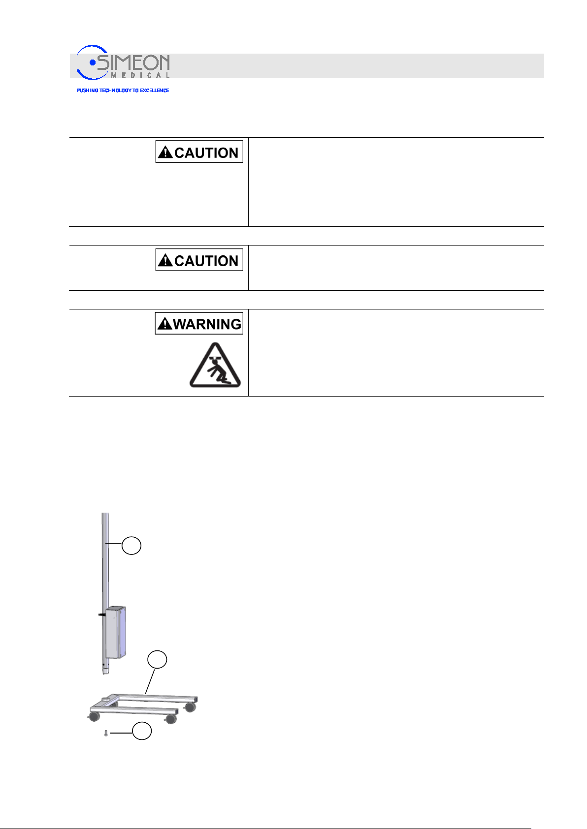
Installation Instructions Surgical LightingSim.LED 450/500/700/5000/7000 SC/MC
6
4
5
4.5 Mounting the mobile variants (illustration similar)
Risk of injury due to pinching!
Multiple parts must be assembled together or mounted onto one
another. As a result, injuries may occur due to pinching.
Proceed cautiously during as s em bl y.
Mount with at least 2 trained and authorised technicians!
Mounting
Identify the spring arm by the product label and mount
exclusively with the approve lights. I n correct allocation
may damage the spring arm and the li g h t.
Danger of injury from falling parts!
Incorrect allocation may damage the spring arm and the
light and/or errors during assembly can compromise the
stability of the lighting system, which can cause the system
to collapse, potentially resul ting in extremely serious
injuries!
4.5.1 Installation of mobile var iants report
Insert the conical end of the stand tube (6) into the cart (4) so
that it is correctly positioned and tighten w ith the inc lu ded scr e w
(5) at a torque of 30 Nm.
Note: A rivet is integrated into the base. Insert the rivet into the hole
in the tube. This prevents an incorrect assembly!
V. 1.7 87
Page 88
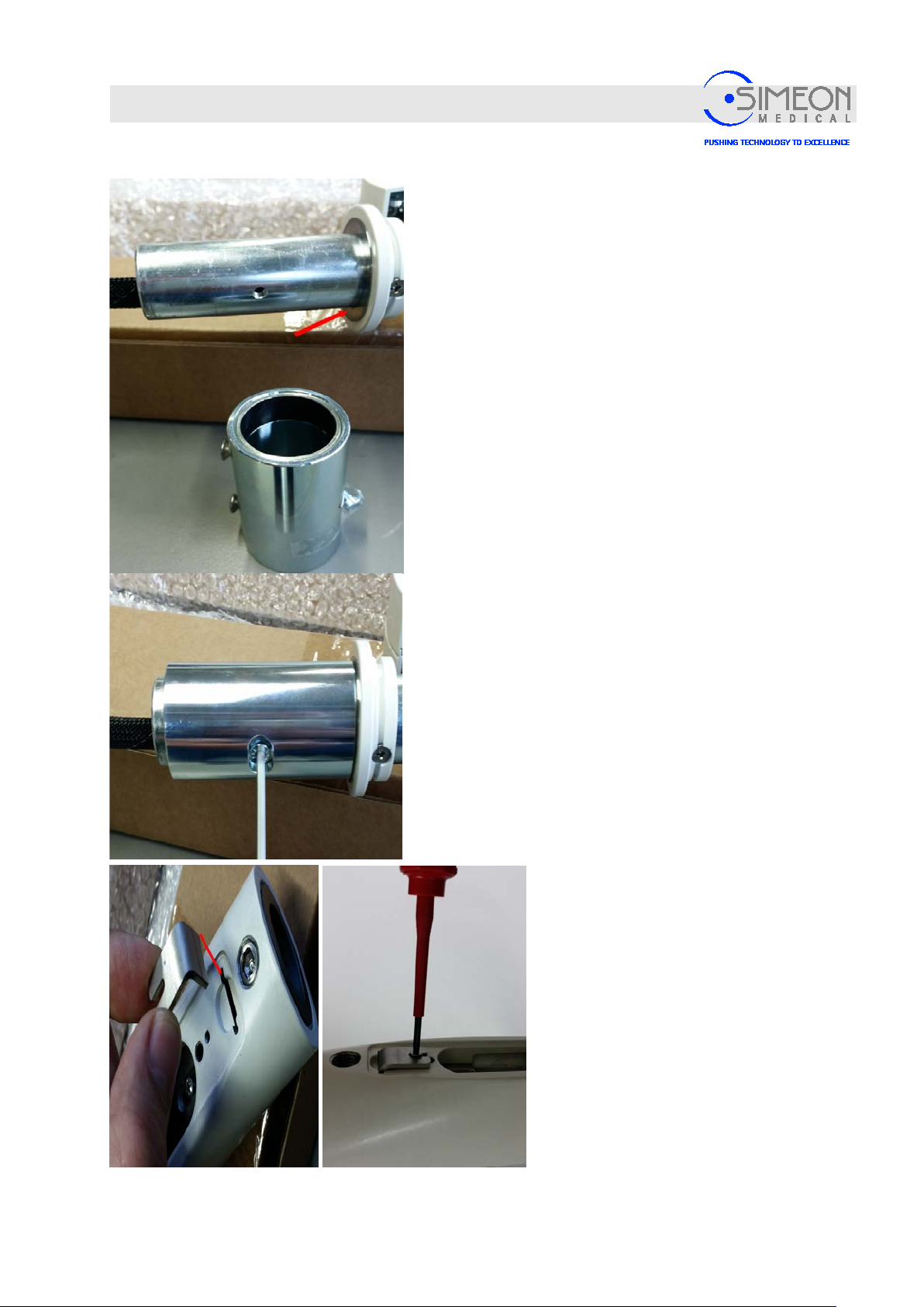
Installation Instructions Surgical LightingSim.LED 450/500/700/5000/7000 SC/MC
Mounting
First, mount the washer and place the sleeve
on the spring arm.
Remove the pre-installed countersunk
screws.
Tighten sleeve with cylinder head screw at a
torque of 4 Nm.
Mount angle plate until stop and screw in.
Tighten brake screw.
V. 1.7 88
Page 89
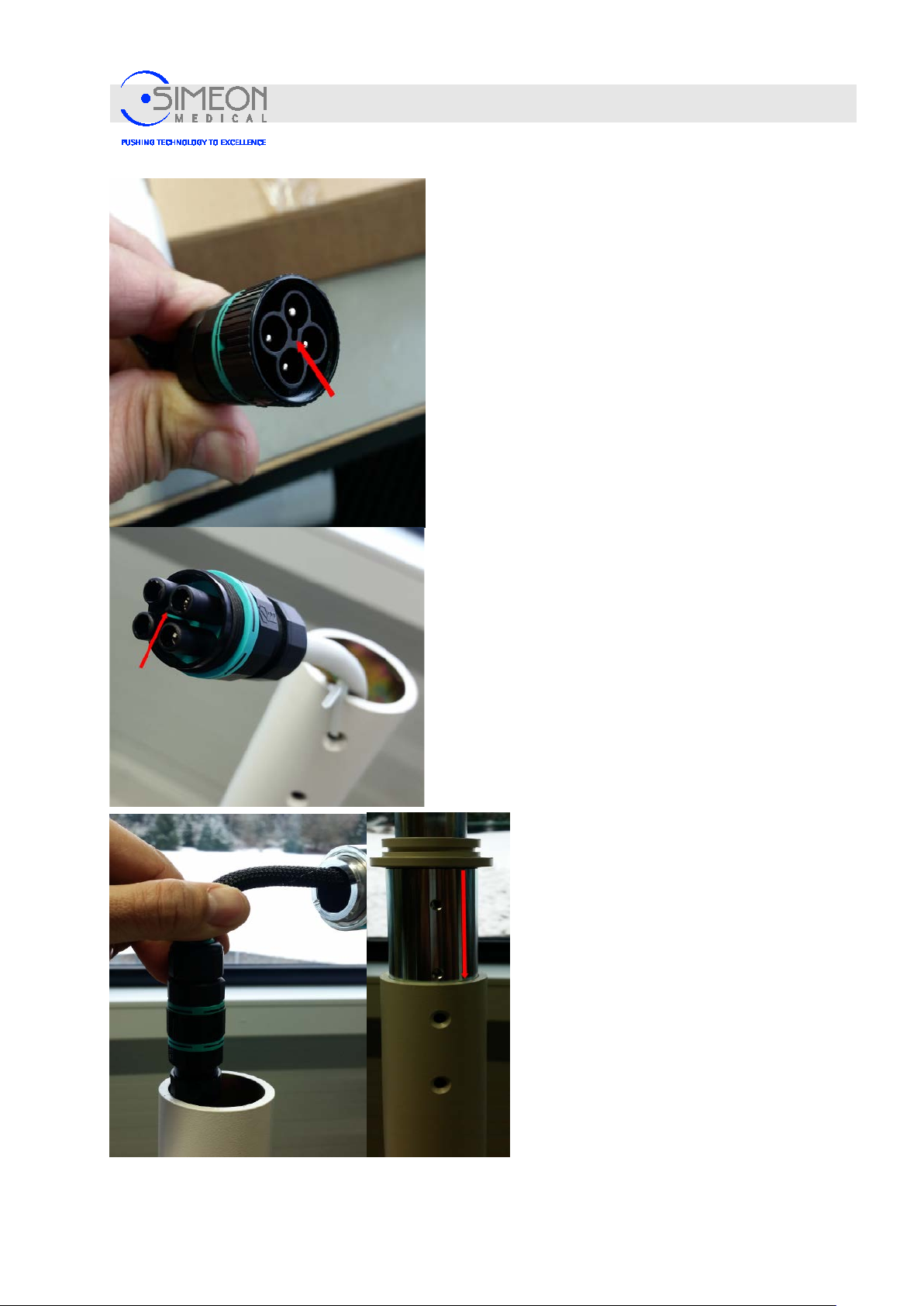
Installation Instructions Surgical LightingSim.LED 450/500/700/5000/7000 SC/MC
Mounting
Insert the pin of the mobile stand connector
into the corresponding groove of the sleeve
and screw together until it stops.
Then remove the cable tie on the stand tube
without letting it fall into the stand tube.
The connector combination is inserted into the
stand tube and the threaded holes in the
adapter sleeve are aligned exactl y vertica lly
with the holes of the stand tube.
After that, the spring arm is inserted into the
stand tube as far as it will go.
V. 1.7 89
Page 90
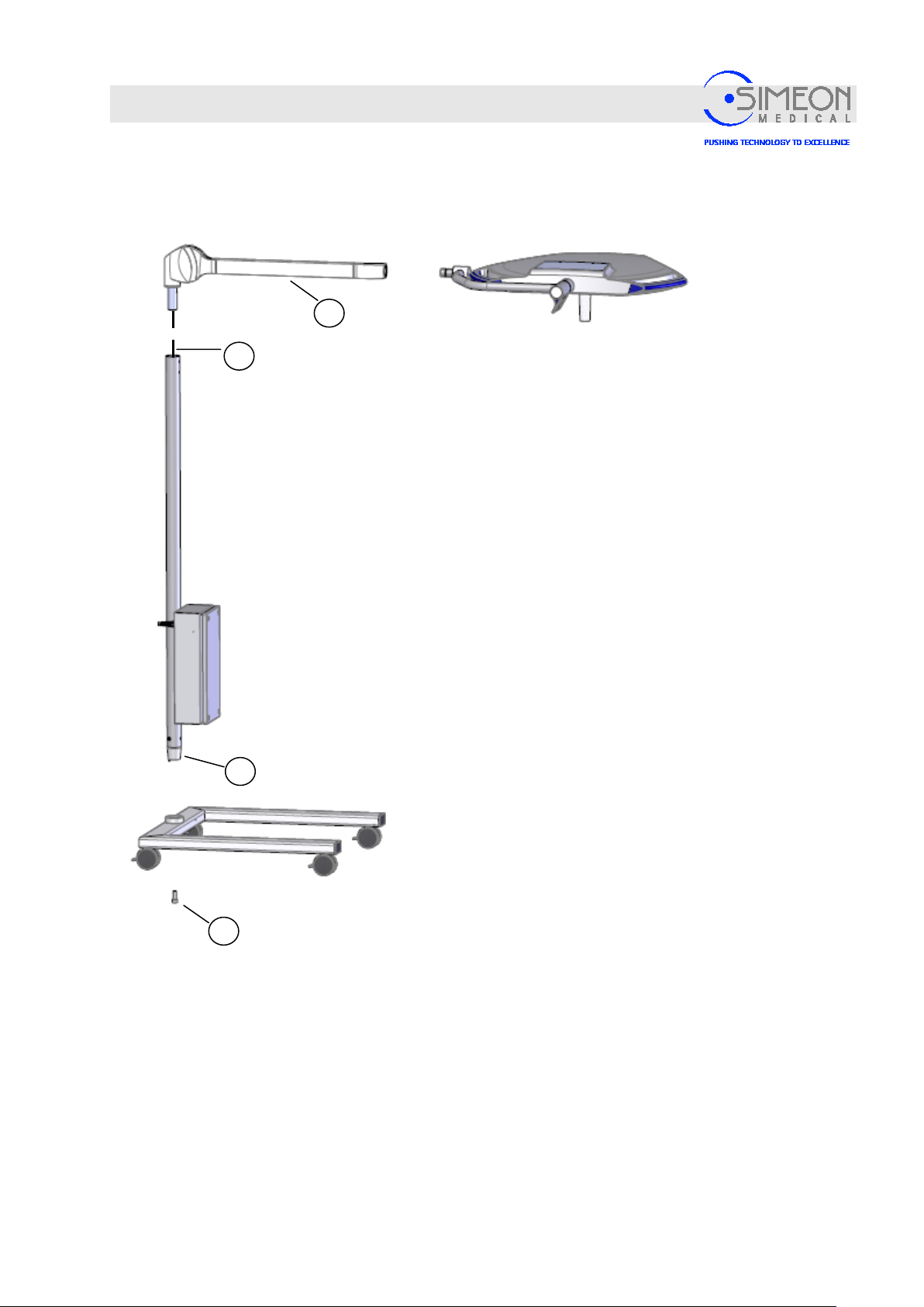
Installation Instructions Surgical LightingSim.LED 450/500/700/5000/7000 SC/MC
7
6
1
5
Mounting
Connect the plug (7) pertaining to the static tube (6) to the cable
connection for the LC spring arm (1).
Insert the LC spring arm (1) into the static tube and secure
using the two Phillips screws (4).
V. 1.7 90
Page 91
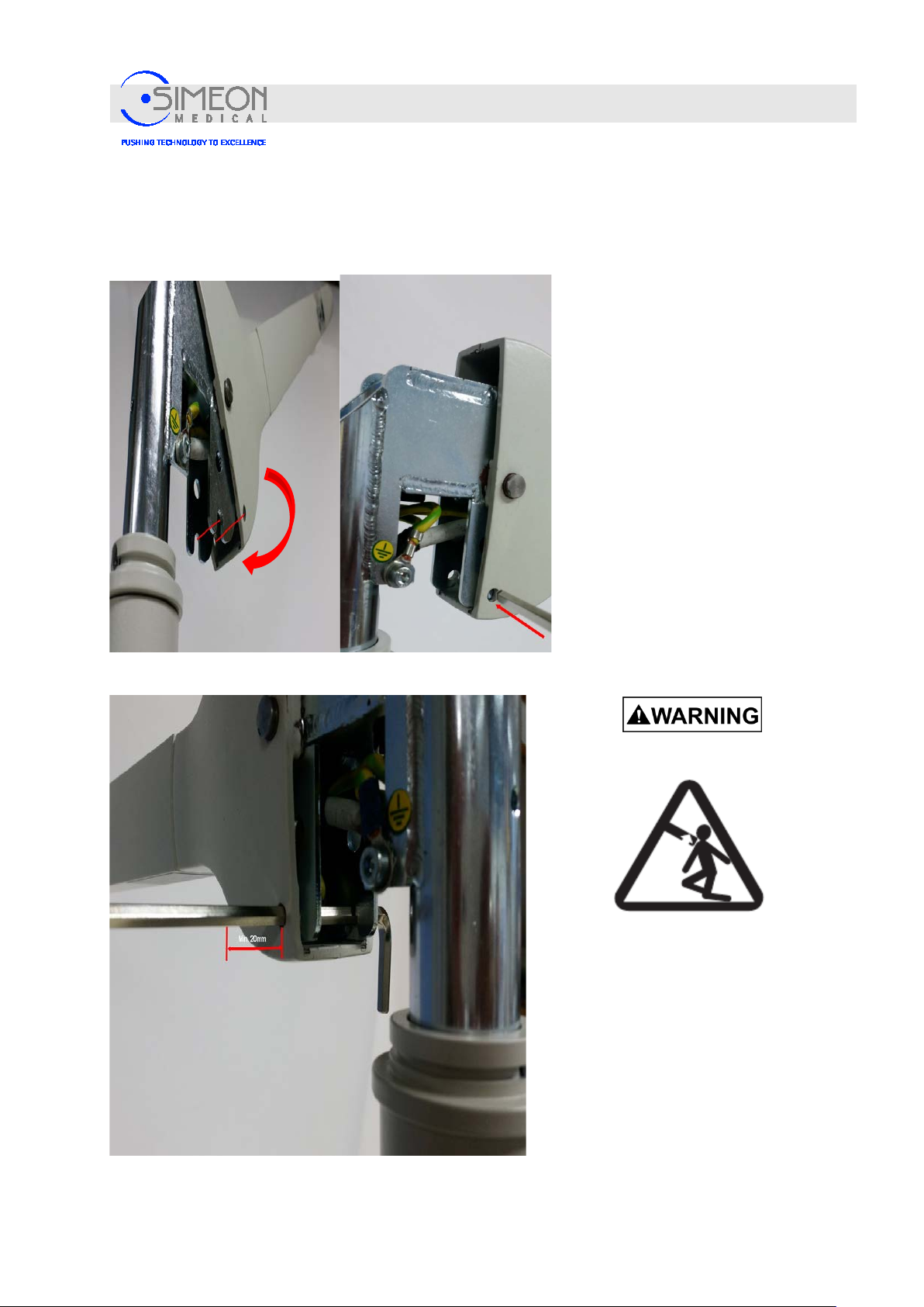
Installation Instructions Surgical LightingSim.LED 450/500/700/5000/7000 SC/MC
4.5.2 Mount spring arm on stand (Module variant only)
Fix all brakes of the mobile stand.
Press spring arm downwards into the
horizontal position so that the holes align
with the slots.
When aligning, insert the SW 5mm
Allen key so that it is completely
inserted and overlaps by at least 20
mm on both sides!
Mounting
Spring arm snapping up
The installed Allen key must not be moved or
removed before
the final assembly of the lights!
V. 1.7 91
Page 92
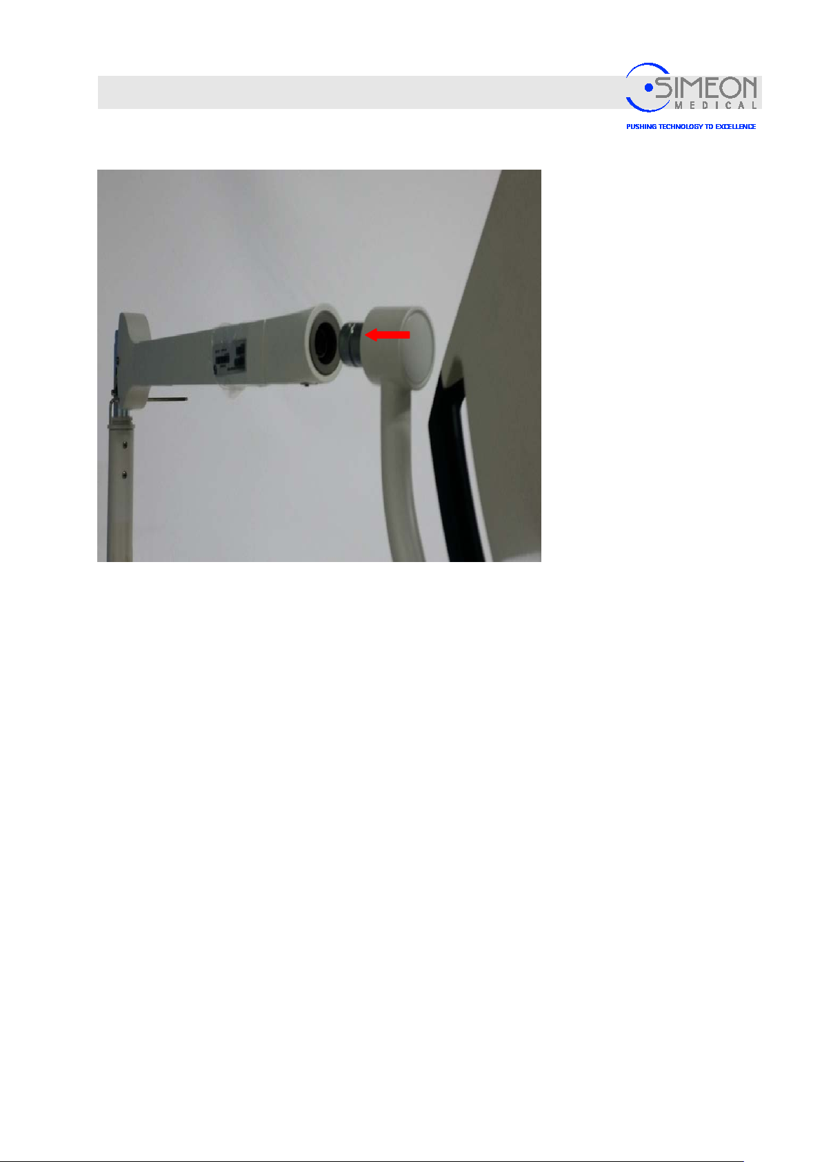
Installation Instructions Surgical LightingSim.LED 450/500/700/5000/7000 SC/MC
Mounting
Align the bearing pin of the light
horizontally and vertically on the
mount and insert as far as it will
go.
V. 1.7 92
Page 93
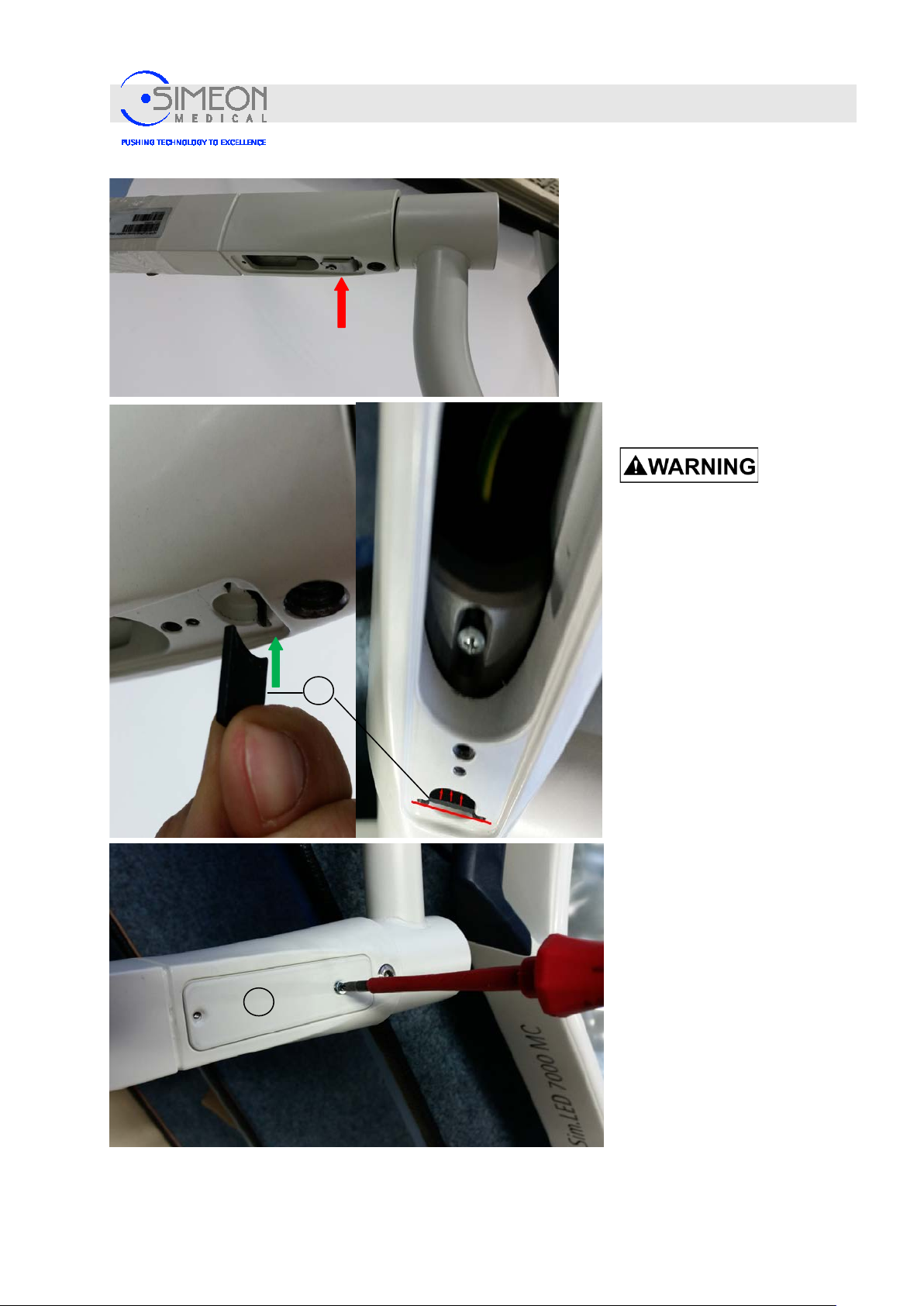
Installation Instructions Surgical LightingSim.LED 450/500/700/5000/7000 SC/MC
2
1
Mounting
Remove the angle plate (red
arrow) and simultaneousl y slide
the locking plate (1) in the correct
position into the corresponding
groove as far as it will go (green
arrow9.
You must be 100% certain that
the locking plate (1) is mounted
as far as it will go!
If the locking plate (1) is not
mounted as far as it will go, the
light can fall down!
Spring arm snapping up
If the locking plate (1) is not
mounted as far as it will go, the
light can fall down and the spring
arm can snap up!
No one may stand beneath the
components of the spring arm
during the mounting process.
It must then be ensured that the
locking plate (1) is mounted as far
as it will go and has not moved
out before the cover (2) for the
locking plate (1) is mounted.
After that, screw on the cover (2)
and make sure that it is fitted
flush with the adjacent areas.
Mount brake screw and adjust
spring force as necessary.
V. 1.7 93
Page 94
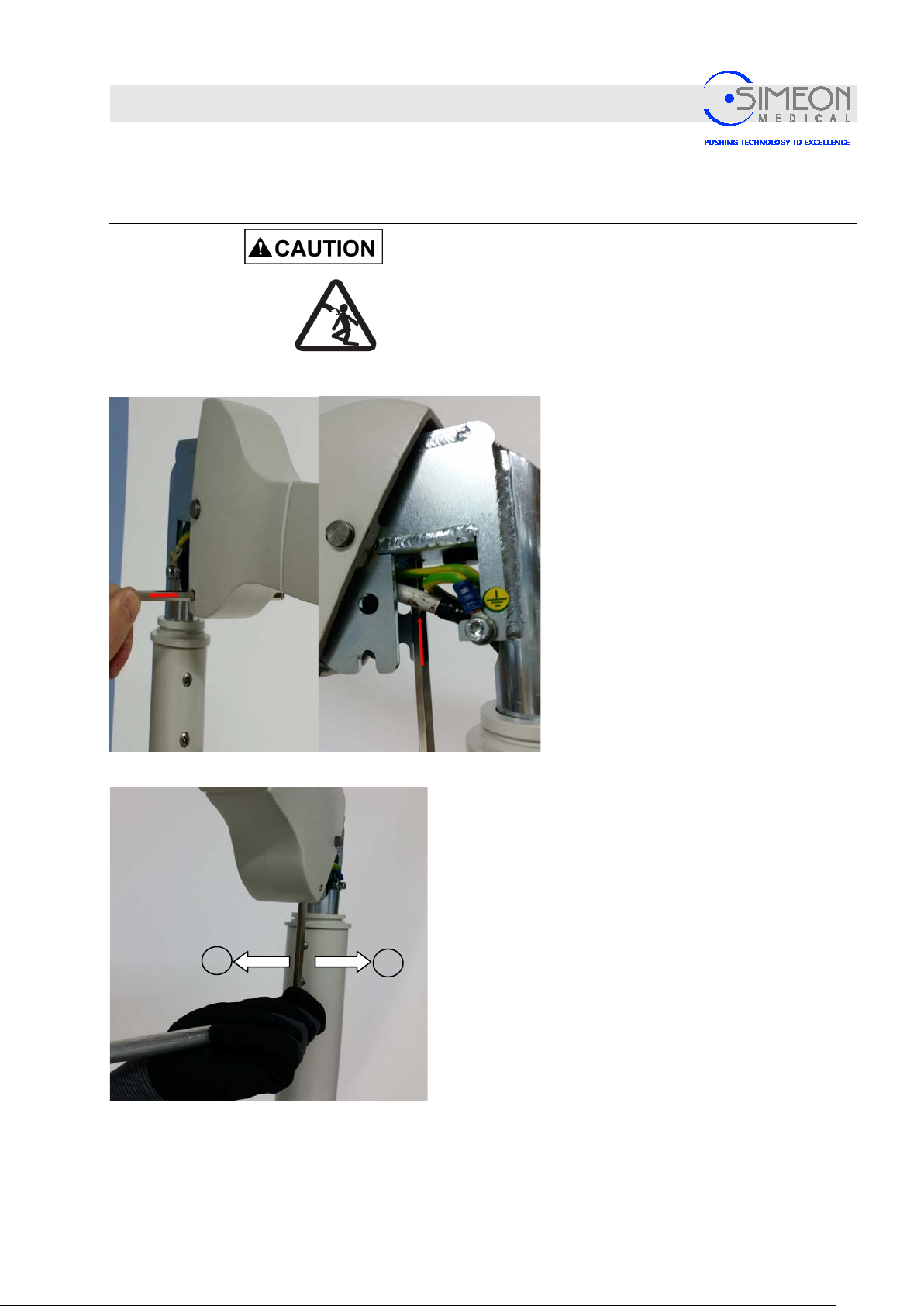
Installation Instructions Surgical LightingSim.LED 450/500/700/5000/7000 SC/MC
1
2
Mounting
4.5.3 Adjust spring force on spring arm (mobile variant only)
Risk of injury due to pinching!
Multiple parts must be assembled together or mounted onto one
another. As a result, injuries may occur due to pinching.
Proceed cautiously during as s em bl y.
Mount with at least 2 trained and authorised technicians!
Remove SW 5mm Allen key (red arrow)
while moving the light slightly.
Move light upward until it stops and hold in
horizontal position.
Insert SW 6mm Allen key into the intended
opening as far as it will go.
Place the enclosed tube on completely and use to turn.
Wear protective gloves.
Insert SW 6mm Allen key into the intended opening as far
as it will go.
Turn Allen key to the left (1) -> spring force will increase.
Turn Allen key to the right (2) -> spring force will be
reduced.
Remove tube and Allen key after setting the spring force.
V. 1.7 94
Page 95
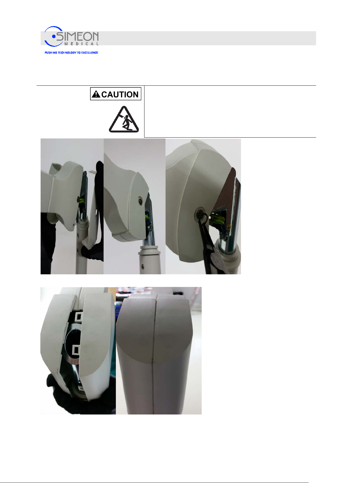
Installation Instructions Surgical LightingSim.LED 450/500/700/5000/7000 SC/MC
4.5.4 Mounting covers on mobile variant
Mounting
Risk of injury due to pinching!
Multiple parts must be assembled together or mounted onto one
another. As a result, injuries may occur due to pinching.
Proceed cautiously during as s em bl y.
Mount with at least 2 trained and authorised technicians!
First, bring the front covers
together in the correct
position and mount them.
After that, mount the
locking rings on both sides
according to
manufacturer’s
specifications.
Bring the rear covers together in the
correct position and mount them.
Pay attention to make sure that the studs
audibly click into place with the
counterpart on the inside and make sure
that the cover is completely closed all the
way around.
.
V. 1.7 95
Page 96

Installation Instructions Surgical LightingSim.LED 450/500/700/5000/7000 SC/MC
Mounting
4.5.5 Establishing power supply for mobile variant
The mobile variant is equipped with commercially-available Schuko plugs.
Danger of electric shock!
The on-site supply line must be disc o n n ected from the
mains on site before further work may be performed! The
supply line must be secured to prevent reconnection.
V. 1.7 96
Page 97
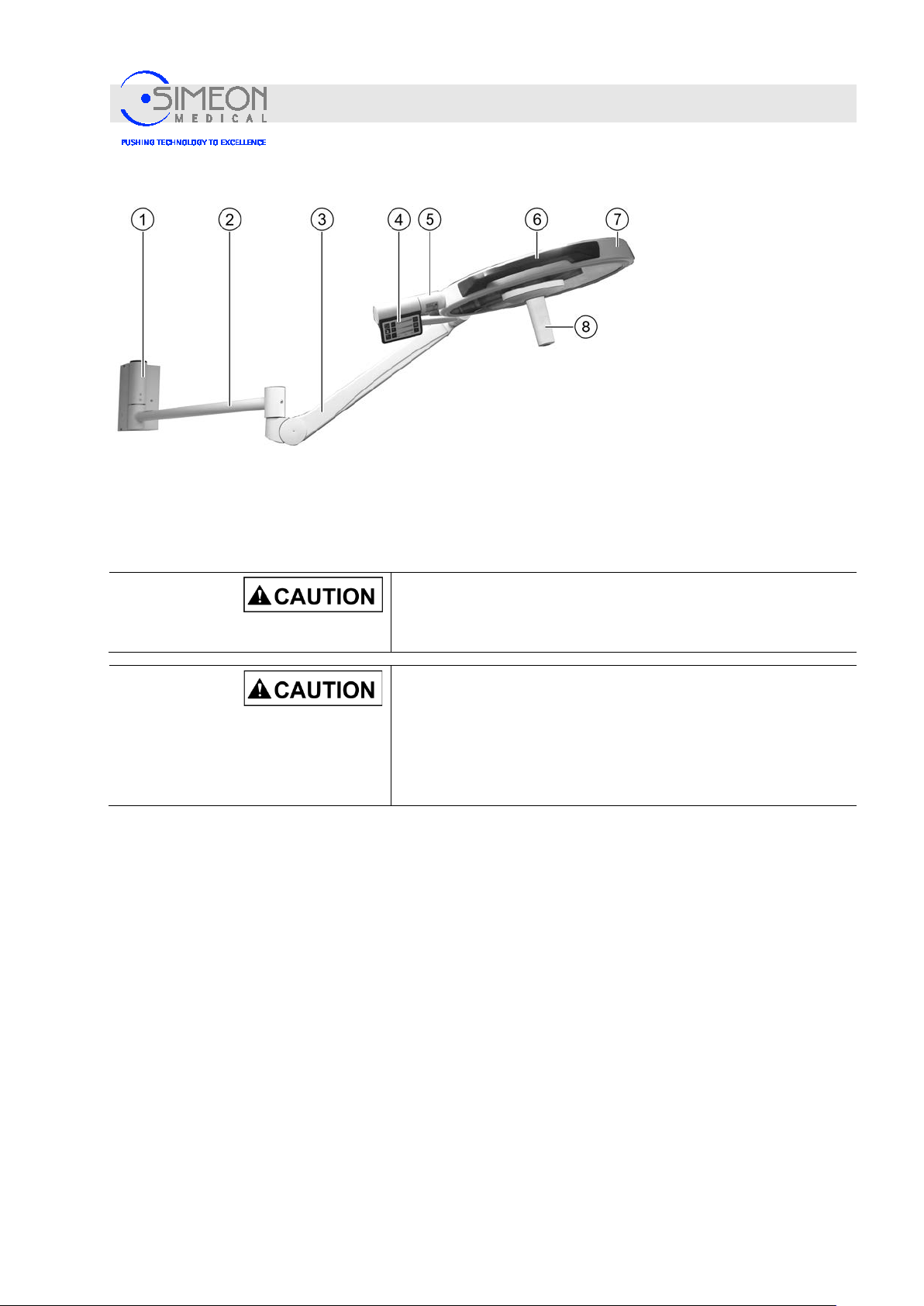
Installation Instructions Surgical LightingSim.LED 450/500/700/5000/7000 SC/MC
1
Wall bearing
5
Cardanic
2
Extension arm
6
Handles (non-sterile)
3
Spring arm with lateral outlet
7
Light head
4
Light controls (MC)
8
Sterilisable handle
4.6 Mounting the Sim.LED 450 wall variant
Mounting
Risk of injury due to falling objects!
Do not hang any objects on the load-bearing system or
fasten them to it!
Risk of injury due to pinching!
Multiple parts must be assembled together or mounted onto one
another. As a result, injuries may occur due to pinching.
Proceed cautiously during as s em bl y.
Mount with at least 2 trained and authorised technicians!
V. 1.7 97
Page 98
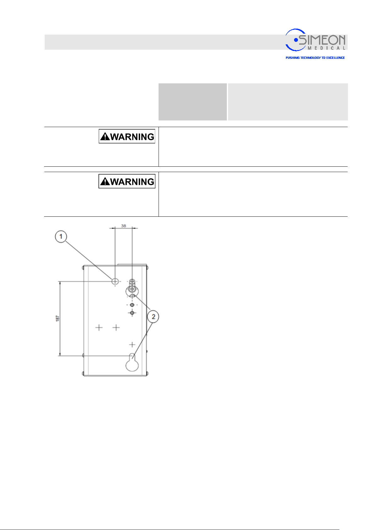
Installation Instructions Surgical LightingSim.LED 450/500/700/5000/7000 SC/MC
Mounting
4.6.1 Mounting the wall bearing
Special tools
Danger of electric shock!
The on-site supply line must be disconnected from the mains on
site before further work may be performed! The supply line must
be secured to prevent reconnection.
Risk of death due to heavy objects!
Parts could fall down while the components are being mounted.
This could cause severe or even fatal injuries.
Spirit level
Torque spanner
Circlip pliers with expansion control
Never attempt to lift heavy objects by yourself.
Allow a structural engineer to inspect and approve the wall,
“Confirmation of static bearing capacity“, page113.
Ensure that the wall surface intended for mounting the wall
bearing is even.
There may be no offset areas in the wall.
Disconnect the on-site supply line (1) from the mains and
safeguard against reconnection.
Ensure that the supply line remains de-energised until
mounting of the light head is completed.
Drill holes (2) into the wall for the stud bolts HSL3G M10/20
in accordance with the specifications of the manufacturer of
the attachment bracket (www.hilti.de) and blow them out
thoroughly.
V. 1.7 98
Page 99
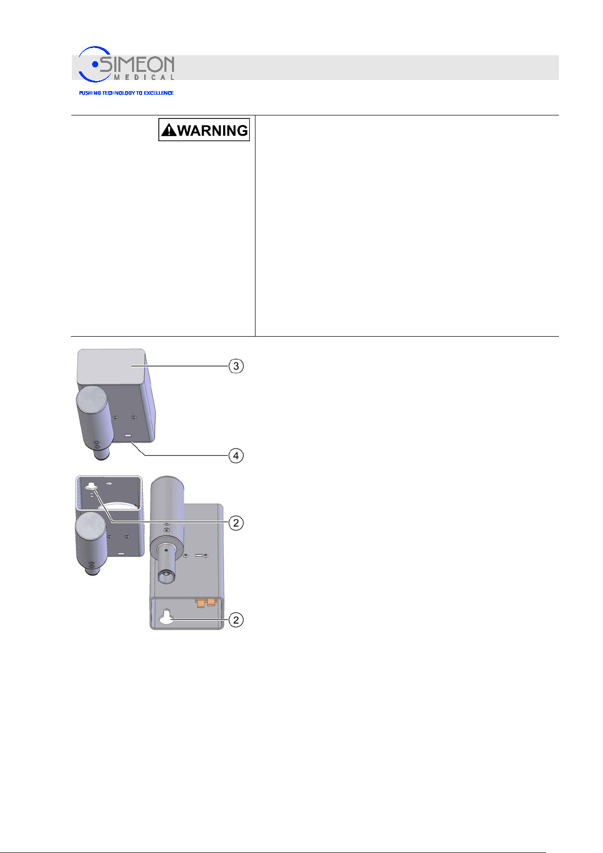
Installation Instructions Surgical LightingSim.LED 450/500/700/5000/7000 SC/MC
Mounting
Risk of death due to improper faste n ing of stud bolts!
The collapse of the wall structure can result in a life-threatening
situation.
In order to mount the wall bearing with through-bolts or stud
bolts, an "Individual case approval" by the competent regional
building authority is mandatorily required.
In the case of unstable, lightweight partition walls, the installation
of a metal rail structure will be absolutely required.
Have the static bearing capacity of the structure tested and
approved by a structural engineer.
Adhere to the specified torque for the stud bolts.
Dispose of used stud bolts.
Do not reuse any used stud bolts.
Unscrew the covers (3, 4) from the wall bearing.
Mount the stud bolts in accordance with the specifications of
the manufacturer of the attachment bracket (www.hilti.de).
Hook the wall bearing's slotted hole (2) onto the stud bolt.
Straighten the wall bearing vertically using a spirit level.
Tighten the nuts for the stud bolts with a 35 Nm torque.
V. 1.7 99
Page 100
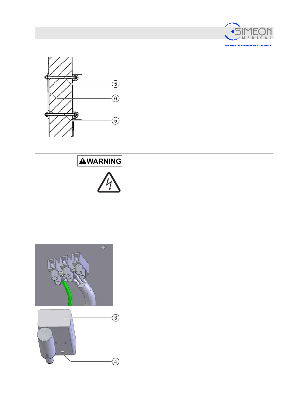
Installation Instructions Surgical LightingSim.LED 450/500/700/5000/7000 SC/MC
Mounting
If the bearing capacity of this wall does not allow for mounting
with stud bolts, the mounting may be performed using throughbolts M8 or threaded rods M8 (5) and a counterplate (6).
4.6.2 Electrical connectio n
Danger of electric shock!
The on-site supply line must be disc o n n ected from the
mains on site before further work may be performed! The
supply line must be secured to prevent re connection.
The power supply for the wall variant must be affixed and
connected in a separate control cabinet.
see Chapter 4.1.11
Connect the supply line to the lustre terminal provided.
Screw the covers (3, 4) back on again.
V. 1.7 100
 Loading...