

Page 1
Super
Combination Boilers
user instructions
Page 2

Page 3

CONTENTS
OPERATING INSTRUCTIONS FOR THE USER
1.1 INTRODUCTION . . . . . . . . . . . . . . . . . . . . . . . . . . . . . . . . . . . . . . . . . . . . . . . . . . . . . . . 2
1.2 APPLIANCE OPERATION
1.3 OPERATING INSTRUCTIONS
1.4 MINIMUM CLEARANCES . . . . . . . . . . . . . . . . . . . . . . . . . . . . . . . . . . . . . . . . . . . . . . . . . 3
1.5 ROUTINE SERVICING
1.6 GENERAL INFORMATION
1.7 SAFETY . . . . . . . . . . . . . . . . . . . . . . . . . . . . . . . . . . . . . . . . . . . . . . . . . . . . . . . . . . . . . . 4
VERY IMPORTANT!
2 YEAR GUARANTEE
IN ORDER TO OBTAIN THE SECOND YEAR’S COVER,
PLEASE REGISTER YOUR BOILER BY SENDING IN
THE ENCLOSED GUARANTEE CARD, OR PHONING OUR
SERVICE DEPARTMENT WITH THE DETAILS ON: 01246 471950
Page 4
2
OPERATING INSTRUCTIONS FOR THE USER
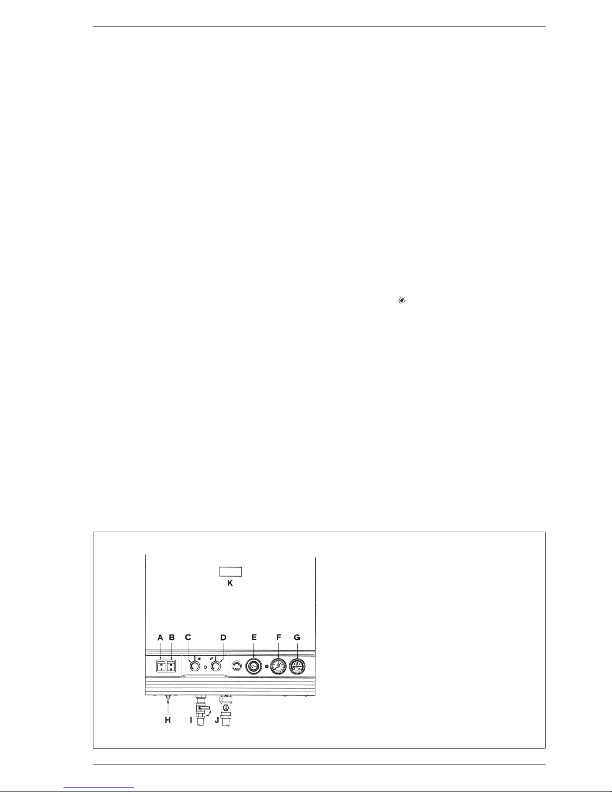
Fig. 1
KEY
A Clock override switch
B Summer/Winter switch
C C.H. thermostat
D D.H.W. thermostat
E Time clock
F Pressure gauge
G Temperature gauge
H Overheat thermostat reset button
I D.H.W. inlet valve
J Gas service cock
K Viewing window
THE GAS SAFETY (INSTALLATION AND USE) REGULATIONS
1994. It is the law that all gas appliances are installed by a
competent person, in accordance with the above regulations. Failure to install appliances correctly could lead to prosecution. It is in your own interest, and that of safety, to
ensure that the law is complied with.
It is essential that the appliance is correctly earthed.
An electricity supply of 240 V - 50 Hz fused at 3 A is
required.
Read these instructions carefully before attempting to operate the appliance.
1.1 INTRODUCTION
The Sime “SUPER” family is a fully automatic, wall mounted, room sealed, fan assisted range of combination boilers.
When operating in winter mode, the appliance provides
central heating as required and produces instantaneous hot
water upon demand. When operating in summer mode, the
central heating is not operational however the appliance
continues to supply hot water whenever it is required.
The heat output is automatically controlled by the fully
modulating gas valve (within its pre-set limits), and there are
user adjustable thermostats to control the temperature of
both central heating and domestic hot water.
Temperature and pressure gauges are fitted and an overheat
thermostat is incorporated to protect against fault conditions.
1.2 APPLIANCE OPERATION
A demand of hot water will be sensed by the appliance
detecting water flow (providing that the flow rate is above
2.8 l/m - 0.62 gal/min).
The fan will start and the pilot will light, immediately followed by the main burner at full output. If the draw off
rate is near the maximum design flow rate the appliance
will run continuously at full output until a tap is either
turned off or the flow rate is reduced in which case the
heat output will reduce accordingly to maintain a steady
temperature.
Hot water is made available almost immediately at the
appliance outlet, but the final temperature and time
taken for the hot water to reach a tap depends upon the
thermostat setting, the rate at which water is drawn off,
and the length of the pipe between the boiler and the
tap.
When the tap is turned off, the appliance will revert to
C.H. mode (if set on winter position) otherwise the burner
and pilot will be extinguished pending the next demand for
hot water.
1.3 OPERATING INSTRUCTIONS
1.3.1 To light the appliance (see fig. 1)
– Check that the electricity supply is off and that the
D.H.W. isolation valve (I) is in the open position (lever
vertical). Check that the gas supply is on.
– Turn the Summer/Winter switch (B) to SUMMER (water
only) position “ ”.
– Switch on the electricity supply and full open any
D.H.W. tap. The burner will light. Check that the burner
has lit by looking through the viewing window (K). If the
burner fails to light, press the overheat thermostat reset
button (H) once and the burner should now light. Turn
off the tap.
– Check that the room thermostat (if fitted) is calling for
heat and turn the clock override switch (A) to the ON
position “●”. Turn the heating thermostat (C) to maximum (fully clockwise).
– Turn the Summer/Winter switch to the WINTER position
“❄" and the burner will light to serve the heating load.
– Turn the clock override switch to the clock position “¹”
and set the clock (as described in section 1.6.4) to the
required settings.
Set the Summer/Winter switch (and the room thermostat if fitted), to the desired position and set the required temperature for the C.H. and D.H.W. by rotating the
thermostats (C - D) clockwise to increase or anticlockwise to decrease the temperature.
Page 5

3
NOTE: when operating in winter mode, priority is
automatically given to providing hot water when the
demand arises.
1.3.2 To turn the appliance off (see fig. 1)
– For short periods:
Set the Summer/Winter switch (B) to SUMMER position
“ ”. When required restore the switch to the WINTER
position “❄" and turn on the D.H.W. isolation valve.
– For longer periods:
Set the Summer/Winter switch (B) to SUMMER position
“ ” and isolate the gas service cock (J).
When required restore the switch to the WINTER position “❄" and turn on the D.H.W. isolation valve.
Do not isolate the mains electricity or gas supply if frost
protection is required. The built in frost thermostat will
provide frost protection only if the gas and electrical
supplies are maintained.
NOTE: when gas and electrical supplies must be
turned off, the entire system should be drained,
including the domestic water system.
1.4 MINIMUM CLEARANCES
The following MINIMUM CLEARANCES must be available
for servicing the appliance:
1.5 ROUTINE SERVICING
To ensure continued efficient operation of the appliance, it
is recommended that it is checked and serviced as necessary at regular intervals.
The frequency of servicing will depend upon the particular
installation conditions and usage but in general once a year
should be adequate. It is the law that any service work
must be carried out by a competent person such as British
Gas or other Corgi registered personnel.
1.6 GENERAL INFORMATION
1.6.1 Appliance overheat thermostat
The appliance is fitted with a safety cut-out thermostat. In
the event of overheating this will interrupt the power supply and prevent the appliance from functioning.
If this occurs, allow the appliance to cool and press the
overheat thermostat reset button (H fig. 1) once and light
the boiler as described in section 1.3.1 above.
If the cut-out condition is repeated, turn off the electrical
supply and consult your installer or service engineer.
1.6.2 Pressure/temperature gauge
The gauges (G - F fig. 1) on the facia panel indicate the
approximate system temperature and pressure. If the normal running pressure is seen to decrease over a period of
time there is a water leak and you should consult your
installer or service engineer.
1.6.3 Electrical supply
The mains plug used must be a 3 pin type to BS1363, and
fused at 3 A. THIS APPLIANCE MUST BE EARTHED.
NOTE: an interruption in the electricity supply whilst
the burner is alight may cause the overheat thermostat to operate. If this is suspected, depress the reset
button (H fig. 1) once.
TO CONNECT A PLUG
As the colour of wires in the mains lead of this appliance
may not correspond with the coloured markings identifying
the terminals in your plug, proceed as follows:
the wire which is coloured green and yellow must be connected to the terminal in the plug which is marked with
the letter E or by the earth symbol - or coloured green and
yellow; the wire which is coloured blue must be connected
to the terminal marked with the letter N or coloured black;
the wire which is coloured brown must be connected to
the terminal marked with the letter L or coloured red.
1.6.4 Setting the heating programmer
To set the heating timeswitch proceed as follows:
– the heating timeswitch is surrounded by 96 teeth,
when pushed in, each one switches on the boiler for 15
minutes;
– push down the teeth corresponding to the HEATING ON
requirements;
– set the clock to the correct time by rotating the dial
clockwise until the arrow corresponds to the current
time;
– if a frost thermostat is fitted see section 1.3.
1.6.5 Ventilation
If the appliance is installed in a cabinet, the latter MUST
NOT be used for storage purposes.
Any ventilation provided for the appliance during installation
MUST NOT be blocked and a periodic check must be made
to ensure that the vents are free from obstructions.
1.6.6 Cleaning
Use only a damp cloth and mild detergent to clean the
appliance outer casing. DO NOT use abrasive cleaners.
mm in
ABOVE THE APPLIANCE CASING 200 8
AT THE R.H.S. 90 3
1
⁄2
AT THE L.H.S. 30 1 1⁄4
BELOW THE APPLIANCE CASING 200 8
IN FRONT OF THE APPLIANCE 450 18
Page 6

4
1.7 SAFETY
It is essential that the instructions in this booklet are strictly
followed for the safe and economical operation of this
appliance. The appliance functions as a fan assisted balanced flue unit. The flue terminal MUST NOT BE OBSTRUCTED under any circumstances. If damaged, turn off the
appliance and consult the installer, service engineer, or
Local Gas Region. If it is known or suspected that a fault
exists on the appliance it MUST NOT be used until the fault
has been rectified by a competent person.
WARNING:
IF A GAS LEAK IS SUSPECTED OR EXISTS, TURN OFF
THE GAS SUPPLY TO THE APPLIANCE AT THE GAS SERVICE COCK. DO NOT OPERATE ANY ELECTRICAL SWITCHES. DO NOT OPERATE ANY ELECTRICAL APPLIANCE.
OPEN ALL WINDOWS AND DOORS. DO NOT SMOKE.
EXTINGUISH ALL NAKED LIGHTS. CONTACT THE
LOCAL GAS REGION IMMEDIATELY.
Page 7

Page 8

Cod. 6233233A
hh ee aa tt ii nn gg pp rr oo dd uucc tt ss uu.. kk .. ll tt dd ..
Jubilee Works - Middlecroft Road - Staveley - Chesterfield - Derbyshire S 43 3XN
Tel. 01246/471950 - Fax 01246/281822
For service enquiries and boiler faults contact our service company on:
Tel. 01246/470777 - Fax 01246/470094
 Loading...