

Page 1
Supplied By www.heating spares.co Tel. 0161 620 6677
Superior Ci EI
Installation, Servicing
& User Instructions
IRL
Page 2

Supplied By www.heating spares.co Tel. 0161 620 6677
Page 3
Supplied By www.heating spares.co Tel. 0161 620 6677
Please refer to commissioning instructions for filling in the log book
Note: All CORGI registered installers carry a CORGI ID Card.
You can check your installer is CORGI Registered by calling 01256 372300
SIME BOILERS
Installer checklist
Please remember to carry out the following checks after installation. This will achieve complete customer satis-
faction, and avoid unnecessary service calls. A charge will be made for a service visit where the fault is not due to
a manufacturing defect.
– Has a correct by-pass been fitted and adjusted?
– Has the system and boiler been flushed?
– Is the system and boiler full of water, and the correct pressure showing on the pressure gauge (if a sealed,
pressurised system is installed)?
– Is the Auto Air Vent open (if fitted to the system)?
– Has the pump been rotated manually?
– Is the gas supply working pressure correct?
– Is the boiler wired correctly? (See installation manual).
– Has the customer been fully advised on the correct use of the boiler, system and controls?
– Has the log book provided been completed?
CONTENTS
1 TECHNICAL FEATURES AND DIMENSIONS . . . . . . . . . . . . . . . . . . . . . . . . . . . . . . . . . . . . . . . . . . . . . . . . . . . . . . 1
2 GENERAL REQUIREMENTS FOR INSTALLATION . . . . . . . . . . . . . . . . . . . . . . . . . . . . . . . . . . . . . . . . . . . . . . . . . . 4
3 INSTALLING THE BOILER . . . . . . . . . . . . . . . . . . . . . . . . . . . . . . . . . . . . . . . . . . . . . . . . . . . . . . . . . . . . . . . . . . . . . 8
4 COMMISSIONING AND TESTING . . . . . . . . . . . . . . . . . . . . . . . . . . . . . . . . . . . . . . . . . . . . . . . . . . . . . . . . . . . . . . . 14
5 ROUTINE SERVICING INSTRUCTIONS . . . . . . . . . . . . . . . . . . . . . . . . . . . . . . . . . . . . . . . . . . . . . . . . . . . . . . . . . . . 15
6 FAULT FINDING . . . . . . . . . . . . . . . . . . . . . . . . . . . . . . . . . . . . . . . . . . . . . . . . . . . . . . . . . . . . . . . . . . . . . . . . . . . . . . 16
7 INTERNAL WIRING DIAGRAMS . . . . . . . . . . . . . . . . . . . . . . . . . . . . . . . . . . . . . . . . . . . . . . . . . . . . . . . . . . . . . . . . 18
8 REPLACEMENT OF PARTS . . . . . . . . . . . . . . . . . . . . . . . . . . . . . . . . . . . . . . . . . . . . . . . . . . . . . . . . . . . . . . . . . . . . 20
9 EXPLODED VIEWS . . . . . . . . . . . . . . . . . . . . . . . . . . . . . . . . . . . . . . . . . . . . . . . . . . . . . . . . . . . . . . . . . . . . . . . . . . .22
Page 4

Supplied By www.heating spares.co Tel. 0161 620 6677
Page 5
Supplied By www.heating spares.co Tel. 0161 620 6677
1.1 INTRODUCTION
The Sime “SUPERIOR Ci EI” is a range of wall mounted cast
iron boilers. The combustion system is fan assisted and has a
small balanced telescopic flue.
The appliance is supplied suitable for use with natural gas and
incorporated a direct burner ignition system.
The appliance is supplied with a concentric air and flue duct
suitable or wall thickness up to 740 mm [29 in] although
extension duct kits are available and may be used up to a total
flue length of 2.5 m [100 in].
The combined flue and air duct can exit the boiler from either
side or from the rear of the appliance.
A vertical extension and additional flue elbow may he fitted. If
required, the boilers can also be fitted with a separate twin
flue kit [see section 3 for details].
The boiler is designed for use with sealed primary water
systems and is supplied fully assembled and complete with
compression joints for simple connection to the heating
system. If the wall thickness is less than 0.5 in [19 in) the
appliance can be installed from inside the room without
access to the external wall although a wall liner is required.
This is available as an optional extra. Full details are given in
section 3.
The boiler can be used with a 230V room thermostat [class
II according to EN 60730.1].
1
1 TECHNICAL FEATURES AND DIMENSIONS
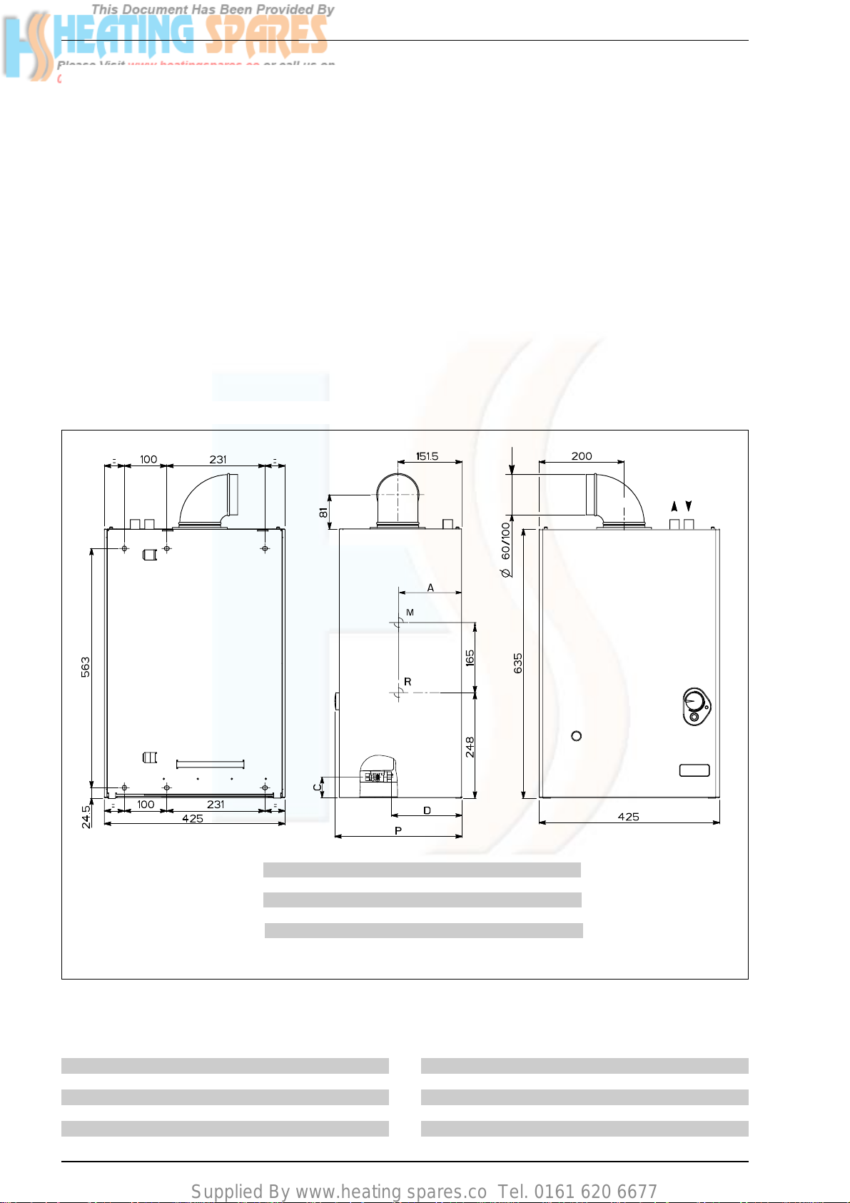
1.2 DIMENSIONAL DETAILS
Fig. 1
TABLE 2 - Minimum clearances
ABOVE THE APPLIANCE CASING 200 mm 8 in
AT THE R.H.S. 5 mm 1/4 in
AT THE L.H.S. 5 mm 1/4 in
BELOW THE APPLIANCE CASING 10 0 m m 4 i n
IN FRONT OF THE APPLIANCE 450 mm 18 in
TABLE 1 - Connections
M CH Flow 22 mm Compression
R CH Return 22 mm Compression
G Gas Rc
1
/2”
1
/2” in BSP female
Superior 40 - 50 - 60 Ci EI Superior 80 Ci EI
P mm 290 350
Amm 150 192
Cmm 49 35
Dmm 167 227
Page 6
Supplied By www.heating spares.co Tel. 0161 620 6677
2
1.3 GENERAL DATA
TABLE 3a - Nominal boiler ratings (2 minutes after lighting) for Superior 40 Ci EI
MODE OUTPUT INPUT (N.C.V.) INPUT (G.C.V.) BURNER PRESSURE
kW Btu/h kW kW Btu/h mbar inwg
CENTRAL HEATING RANGE 8.8 30,000 10.0 11.1 37,800 5.4 2.2
9.1 31,000 10.3 11.4 38,900 6.0 2.4
9.4 32,000 10.6 11.8 40,100 6.4 2.6
9.7 33,000 10.9 12.1 41,200 6.7 2.7
10.0 34,000 11.2 12.4 42,300 7.1 2.9
10.3 35,100 11.5 12.8 43,500 7.5 3.0
10.6 36,100 11.8 13.1 44,600 7.9 3.2
10.9 37,100 12.1 13.4 45,700 8.3 3.3
11.2 38,100 12.4 13.8 46,900 8.7 3.5
11.5 39,200 12.7 14.1 48,000 9.2 3.7
X* 11.8 40,200 13.0 14.4 49,100 9.6 3.9
*Factory setting
TABLE 3b - Nominal boiler ratings (2 minutes after lighting) for Superior 50 Ci EI
MODE OUTPUT INPUT (N.C.V.) INPUT (G.C.V.) BURNER PRESSURE
kW Btu/h kW kW Btu/h mbar inwg
CENTRAL HEATING RANGE 11.9 40,500 13.2 14.7 49,900 9.7 3.9
12.2 41,500 13.5 15.0 51,000 10.2 4.1
12.5 42,600 13.8 15.3 52,200 10.7 4.3
12.8 43,600 14.1 15.7 53,300 11.3 4.5
13.1 44,600 14.5 16.1 54,800 11.9 4.8
13.4 45,600 14.8 16.4 55,900 12.5 5.0
13.7 46,700 15.1 16.7 57,100 13.0 5.2
14.0 47,700 15.4 17.1 58,200 13.6 5.5
14.3 48,700 15.7 17.4 59,300 14.1 5.7
X* 14.6 49,700 16.0 17.8 60,500 14.7 5.9
*Factory setting
TABLE 3c - Nominal boiler ratings (2 minutes after lighting) for Superior 60 Ci EI
MODE OUTPUT INPUT (N.C.V.) INPUT (G.C.V.) BURNER PRESSURE
kW Btu/h kW kW Btu/h mbar inwg
CENTRAL HEATING RANGE 14.7 50,000 16.4 18.2 62,000 10.4 4.2
15.0 51,000 16.7 18.5 63,100 10.8 4.3
15.3 52,100 17.0 18.9 64,300 11.2 4.5
15.6 53,100 17.3 19.2 65,400 11.6 4.7
15.9 54,100 17.6 19.5 66,500 12.0 4.8
16.2 55,200 17.9 19.9 67,700 12.5 5.0
16.5 56,200 18.3 20.3 69,200 13.0 5.2
16.8 57,200 18.7 20.8 70,700 13.6 5.5
17.1 58,200 19.0 21.1 71,800 14.1 5.7
X* 17.5 59,600 19.4 21.5 73,300 14.7 5.9
*Factory setting
Page 7
Supplied By www.heating spares.co Tel. 0161 620 6677
3
40 Ci EI 50 Ci EI 60 Ci EI 80 Ci EI
Burner Injector 1
ø mm 3.25 3.25 3.55 4.10
Max. gas consumpt.
m3/h
1,38 1,69 2,05 2,75
System Press min bar 0.12
max bar 3
Adjustable Flow Temp Pump mode min °C 50 on - 60 off
Pump mode max °C
72 on - 84 off
Safety stat °C 105
Re-Start Delay Seconds 180
Anti-Inertia Temp. °C 90 off - 95 on
Max. working temp. °C 84
Boiler pressure drop ∆t 11°C mbar 100 150 220 330
Electricity Supply
230V/50Hz
Internal Fuse F 2A
Power Consumption W 55556065
Weight kg 46 46 46 57
TABLE 4 - General specifications
TABLE 3d - Nominal boiler ratings (2 minutes after lighting) for Superior 80 Ci EI
MODE OUTPUT INPUT (N.C.V.) INPUT (G.C.V.) BURNER PRESSURE
kW Btu/h kW kW Btu/h mbar inwg
CENTRAL HEATING RANGE 17.6 59,900 19.9 22.1 75,200 8.5 3.4
18.2 62,000 20.5 22.8 77,500 9.0 3.6
18.8 64,000 21.2 23.5 80,100 9.6 3.9
19.3 65,700 21.7 24.1 82,000 10.2 4.1
19.9 67,800 22.3 24.8 84,300 10.8 4.3
20.5 69,800 22.9 25.4 86,600 11.4 4.6
21.1 71,900 23.6 26.2 89,200 12.2 4.9
21.7 73,900 24.2 26.9 91,500 12.8 5.1
22.2 75,600 24.7 27.4 93,400 13.4 5.4
22.8 77,600 25.3 28.1 95,600 14.0 5.6
X* 23.4 79,700 26.0 28.9 98,300 14.7 5.9
*Factory setting
Page 8
Supplied By www.heating spares.co Tel. 0161 620 6677
2.1 STATUTORY REQUIREMENTS
GAS SAFETY [INSTALLATION AND USE REGULATIONS [as
amended]. It is the law that a registered person, in accordance with the above regulations, installs all gas appliances.
Failure to install appliances correctly could lead to prosecution. It is in your own interest, and that of safety, to ensure
that the law is complied with.
In addition to the above regulations, this appliance must be
installed in accordance with the current lEE Wiring
Regulations [BS 7871], Local Building Regulations, the
Building Standards [Scotland] [Consolidation] Regulations,
Byelaws of the local water undertaking, and Health and Safety
Document No 635 ‘The Electricity at Work Regulations 1989’.
It should also be in accordance with the relevant recommendations in the current editions of the following British
Standards and Codes of Practice: BS5449, BS5546,
BS5440: 1, B5544O:2, BS6798, BS6891, and BG.DM2,
BS7074, and BS5482 for propane installations.
Manufacturer’s instructions must NOT be taken in any way as
over-riding statutory obligations.
2.2 BOILER POSITION
In sighting the boiler, the following limitations MUST be observed:
The boiler is not suitable for external installation. The position
selected for installation should be within the building, unless
otherwise protected by a suitable enclosure, and MUST allow
adequate space for installation, servicing, and operation of
the appliance, and for air circulation around it [section 2.4].
This position MUST allow for a suitable flue termination to be
made. The boiler must be installed on a flat vertical wall which
is capable of supporting the weight of the appliance, and any
ancillary equipment.
If the boiler is to be fitted in a timber framed building it should
be fitted in accordance with the Institute of Gas Engineers
document for Gas Installations In Timber Frame Housing,
Reference 1SF UP 7:1998. If in doubt, advice must be sought
from the gas supplier.
If the appliance is installed in a room containing a bath or
shower, any electrical switch or control utilising mains electricity must be so situated that it cannot be touched by a person
using the bath or shower. Attention is drawn to the requirements of the current lEE. Wiring Regulations [BS7871], and in
Scotland the electrical provisions of the Building Regulations
applicable in Scotland.
A compartment used to enclose the appliance MUST be designed and constructed specifically for this purpose. An existing
cupboard, or compartment, may be used provided it is modified accordingly.
Where installation will be in an unusual location, special procedures may be necessary. BS6798 gives detailed guidance
on this aspect.
2.3 FLUE TERMINAL POSITION
Detailed recommendations for flue installation are given in
BS5440: 1. The following notes are for general guidance:
The boiler MUST be installed so that the terminal is exposed
to the external air.
It is important that the position of the terminal allows free
passage of air across it at all times.
It is ESSENTIAL TO ENSURE, in practice that products of com-
bustion discharging from the terminal cannot re-enter the
building, or any other adjacent building, through ventilators,
windows, doors, other sources of natural air infiltration, or forced ventilation air conditioning. If this does occur, the appliance MUST be turned OFF IMMEDIATELY and the gas supplier
consulted.
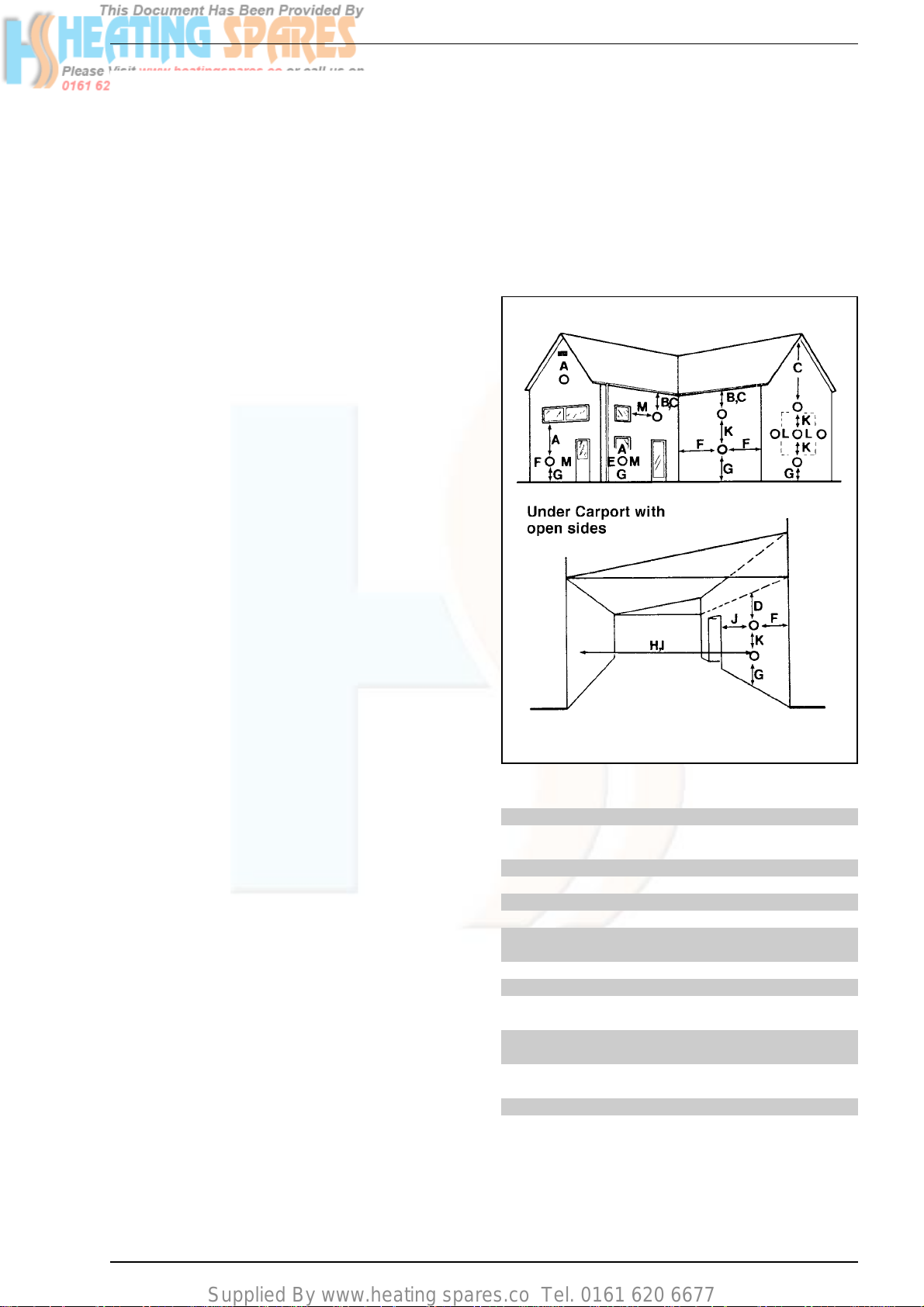
The minimum acceptable dimensions from the terminal to
obstructions and ventilation openings are specified in fig. 2.
If the terminal discharges into a pathway or passageway
check that combustion products will not cause nuisance and
that the terminal will not obstruct the passageway.
Where the lowest part of the terminal is fitted less than 2 m
[78 in] above ground, above a balcony or above a flat root to
which people have access, the terminal MUST be protected
4
2 GENERAL REQUIREMENTS FOR INSTALLATION
Terminal position
Directly below an openable window, air
vent or any other ventilation opening
Below guttering, drain pipes or soil pipes
Below eaves, balconies or carport roof
From vertical drain pipes or soil pipes
From internal or external corners
Above adjacent ground, roof or bal-
cony level
From a surface facing the terminal
From a terminal facing the terminal
From an opening in the carport (eg
door, window into dwelling)
Vertically from a terminal on the
same wall
Horizontally from a terminal on the
same wall
Adjacent to opening
A
B
C/D
E
F
G
H
I
J
K
L
M
Minimum spacing
300 mm 12 in
75 mm 3 in
200 mm 8 in
75 mm 3 in
300 mm 12 in
300 mm 12 in
600 mm 24 in
1,200 mm 48 in
1,200 mm 48 in
1,500 mm 60 in
300 mm 12 in
300 mm 12 in
TABLE 5
Fig. 2
Page 9
Supplied By www.heating spares.co Tel. 0161 620 6677
by a purpose designed guard. Terminal guards are available
from Quinnell, Barrett, and Quinnell, Old Kent Road, London.
State the model C2, [G.C. Part No 382946]
Where the terminal is fitted within 850 mm [34 in) of a plastic or painted gutter or 450 mm [18 in) of painted eaves, an
aluminium shield at least 1,500 mm (59 in] long must be fitted to the underside of the painted surface.
The air inlet outlet flue duct MUST NOT he closer than 25 mm
[1 in] to combustible material.
In certain weather conditions the terminal may emit a plume
of steam. This is normal but positions where this would cause
a nuisance should be avoided.
2.4 VENTILATION REQUIREMENTS
Detailed recommendations for air supply are given in
B55440: 2.
The following notes are for general guidance:
It is not necessary to have a purpose provided air vent in the
room or internal space in which the appliance is in installed.
2.5 GAS SUPPLY
The gas supplier should be consulted at the installation planning stage in order to establish the availability of an adequate
supply of gas.
An existing service pipe MUST NOT be used without prior consultation with the gas supplier.
A gas meter can only be connected by the gas supplier or
their contractor.
An existing meter should be of sufficient size to carry the
maximum boiler input plus the demand of any other installed
appliance. (BS6891: 1988]. The gas required for the boiler is
specified in Table 4.
The governor at the meter must give a constant outlet pressure of 20 mbar [8 in wg] for natural gas when the appliance
is running. The gas supply line should be purged.
NOTE: Before purging open all doors and windows, also
extinguish any cigarettes, pipes, and any other naked
lights.
The complete installation must be tested for gas soundness.
It is important to assure an adequate gas supply to the
appliance. No more than 3 m of 15 mm pipe should be used.
Where the supply exceeds 3 m the pipe should be suitably
sized only reducing to 15 mm for the last 3 m prior to the
appliance.
2.6 ELECTRICITY SUPPLY
The appliance MUST be earthed. A mains supply of 230V 50 Hz single phase is required.
All external controls and wiring MUST be suitable for mains
voltage.
Wiring should he in 3-core PVC insulated cable NOT LESS
than 0.75 mm [24 x 0.2 mm] to BS6500, Table 16. Wiring
external to the boiler MUST be in accordance with current lEE
Wiring Regulations [B5 7671] and local regulations. The supply connection to the flying lead provided MUST be made to a
fused double pole switch, having a 3 mm [1/8 in] contact
separation in both poles, serving only the boiler and system
controls.
The fuse rating should be as per the original instructions. This
connection should be readily accessible and be made adjacent to the boiler. All fuses must be ASTA approved to BS
1362.
2.7 EXTERNAL CONTROLS AND COMPONENTS
The boiler is intended for use with a 230 V room thermostat.
The appliance requires a live feed from this to operate the
appliance and external circulating pump.
The pump MUST be wired to the appliance.
May need more notes when details are available.
The connection is made to the terminal block as described in
section 3.8.1
2.8 WATER SYSTEMS
2.8.1 General
This appliance is designed for connection to the following
types of indirect domestic systems:
– Fully pumped, sealed central heating systems.
– Fully pumped, open vented central heating systems.
The domestic hot water cylinder must be of the indirect type
with a separate feed and vent pipes. Single feed cylinders
must not be used.
The pump, including isolation valves, should be fitted in the
heating flow pipe from the appliance.
The pump should provide suitable flow to maintain an 11°C
temperature rise between the pumped flow and return pipes
connected to the appliance. Details of the appliance pressure
drop are provided in Table 4.
System drain cocks should be fitted at the lowest points in the
system in order to provide adequate drain points.
BS5442 provides information for the protection of the boiler
due to freezing. A frost thermostat should be fitted to the
system controls.
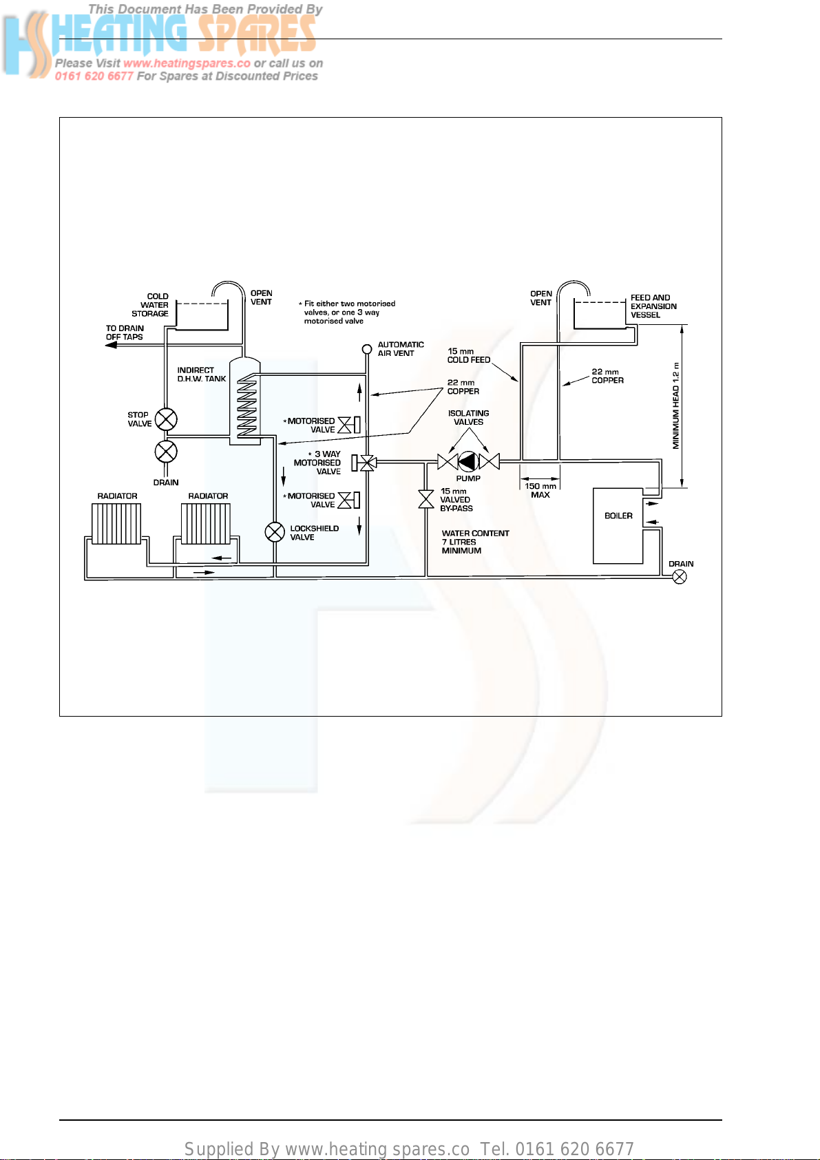
2.8.2 Requirements for open vented systems
A 22 mm copper vent pipe must be connected to the top of
the boiler flow pipe and terminate above the cold feed/expansion tank. It must be suitably positioned to allow any discharge into the cold feed tank/expansion and must be on a continuous rise from the boiler flow pipe where it is connected.
The cold feed/expansion tank must have a capacity of at least
22 litres. The cold feed pipe from the cold feed/expansion
tank should be 15 mm copper.
The cold feed/expansion tank should have a lid. The bottom cold
feed/expansion tank must be no less than 1.2 m (one-point-two)
and no more than 30 m above the top of the appliance.
2.8.3 Requirements for sealed water systems
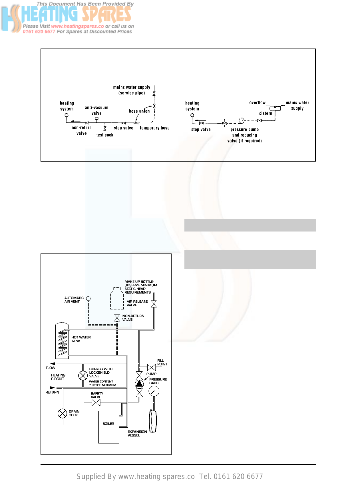
A sealed system must only be filled by a competent person
using one of the approved methods shown in fig. 3.
The system design should incorporate the connections appro-
5
Page 10
Supplied By www.heating spares.co Tel. 0161 620 6677
priate to one of these methods. The system pressure must
not be less than the static head of the system.
A safety valve set at 3 bar must be fitted to the flow pipe exiting the appliance. It should be as close to the appliance as
practical and there shall be no restrictions between it and the
appliance. It should be connected above or to the side of the
pipe centre line in a position that is accessible for testing. The
outlet from the valve should be routed so that any discharge,
water or steam, does not cause a hazardous condition.
A pressure gauge must be fitted to allow the person filling
the system to see it to control the fill pressure. A gauge with
a range of 0 to 5 bar, or similar, is suitable.
A suitable expansion vessel must be fitted to the system. It
should be connected close to the inlet side of the circulating
pump. Its size must be calculated in accordance with BS
5449: pt1: 1997.
The hot water cylinder must be an indirect type and be sui-
table to operate at pressure of 0.35 bar over the pressure at
that of the safety valve, (3.35 bar minimum).
A single feed cylinder must not be used. A low level filling point
must be provided which incorporates a stopcock.
Provision should be made to replace system water losses by
either pre-pressurising the system or fitting a make up vessel
at the highest point of the system. BS 5376: pt2: 1976.
2.8.4 Fully pumped
The heating system design should be based on the following
information:
The appliance pressure drop details are given in Table 4.
A minimum flow rate corresponding to a heating differential
of 11°C must be obtained at all times.
A heating by-pass should be fitted to ensure the previous condition is satisfied.
If thermostatic radiator valves are to be installed, at least one
radiator should be installed without a thermostatic valve
[usually the bathroom radiator].
The combined flow pipe (heating & hot water) should be connected to the 22 mm flow pipe, which exits the appliance at
the rear, top right of the case (top manifold).
The combined return pipe (heating & hot water) should be
connected to the 22 mm return pipe, which enters the
appliance at the rear, top right of the case (bottom manifold).
6
ALTERNATIVE METHODS OF FILLING A SEALED SYSTEM
TABLE 6
Fig. 3
Vessel charge and initial system
pressure
Total water content of system if
using an 8 l (1.76 gal) expansion
vessel is used
To size the expansion vessel for
other system capacities multiply
the system volume by:
bar
psi
l
gal
0.5
7. 3
87
19 .1
.0833
1. 5
21.8
44
9.7
.15 6
1. 0
14.5
64
14.0
.10 9
SEALED WATER SYSTEM
Fig. 4
Page 11
Supplied By www.heating spares.co Tel. 0161 620 6677
7
TYPICAL SYSTEM DESIGN, FULLY PUMPED, OPEN VENTED.
Fig. 5
Page 12
Supplied By www.heating spares.co Tel. 0161 620 6677
3.1 UNPACKING THE BOILER
The standard appliance is supplied in two cardboard carton.
In addition up to two extension duct kits may be used. If the
appliance is to be installed without access to the outside wall,
the wall liner will also be required. Unpack each carton and
check the contents against the following lists:
Appliance package:
– Boiler (appliance + mounting frame)
– Installation, servicing and User instructions
– Wall template
– Fixing screws with wall plugs and washers
Flue package:
– Telescopic flue/terminal assembly
– Flue package [1 x gasket, 2 x ‘O’ rings, 4 screws]
– Flue elbow
– Inner and outer wall seal
– Junction collar + protective metal collar
3.2 PREPARING THE WALL
Before installing the appliance ensure that the chosen location is suitable [section 2.2] and the requirements for flue
position [section 2.3], and minimum clearances, [Table 2 ] are
satisfied. These minimum clearances are essential to provide
access for servicing. Fix the template to the wall in the chosen
position. Mark the position of the two upper fixing holes, the
two lower fixing holes and the flue air duct hole on the appropriate wall. For side flue options it will be necessary to project
a horizontal centre line along the rear wall to the side wall.
Drill the top two fixing holes using a 8 mm masonry drill. Fit
the plastic plugs provided. Cut the hole in the wall for the flue
air duct. The diameter should not be less than 100 mm [4 in]
and must be horizontal. If the hole is not accessible from the
outside of the building, its minimum diameter should be sufficient to allow the insertion of the wall liner 129 mm diameter,
which should be sealed with mortar. The wall liner is available
as an optional extra. Drill the lower two fixing holes using a 8
mm masonry drill. Fit the plastic plugs provided.
3.3 HANGING THE BOILER
Remove the outer case securing screws, located at the
bottom rear of the boiler, and lift the case off the
appliance.
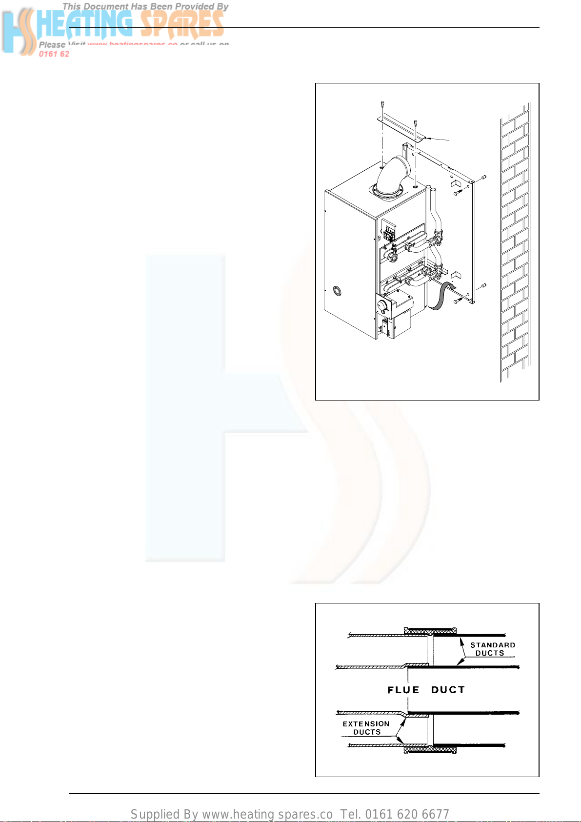
Remove the mounting bracket unscrewing the
two screws and separate the sealed chamber from the boiler
frame. Fix the frame to the wall through the screws supplied
and replace the sealed chamber and casing in position.
3.4 FLUE AND TERMINAL PREPARATION
If the wall thickness is less than 0.5 m [19 in] the flue/air duct
may be fitted without access to the outside wall providing the
optional wall liner kit is used.
[This consists of a steel pipe, 0.5 m long and 129 mm outside diameter with a 1 mm wall thickness].
3.4.1 Cutting & Setting To The Correct Length
Determine whether an extension duct (code 8084804) is
required with reference to the Table 8.
– If any extensions are required
the flue and air ducts should
be joined before proceeding to the next section. The extension ducts should be joined to each other and to the standard
ducts using the following procedure (fig. 7);
– For the flue ducts in turn, push the plain end of the stan-
dard and (if using two or three extensions) extension duct
into the swaged end of the extension duct(s).
– Push an air duct in to the clamp. Join the air ducts (larger
ducts) and tighten the screws an the clamp to connect them.
– Insert the inner flue ducts and ensure the ‘O’ ring seals
are correctly located.
– If the correct length cannot be achieved with the telesco-
pic action of the flue, the end of the extension duct [air and
flue] should be cut shorter. The telescopic action of the flue
can then be used to achieve the overall correct length.
8
3 INSTALLING THE BOILER
Fig. 6
Fig. 7
MOUNTING
BRACKET
Page 13
Supplied By www.heating spares.co Tel. 0161 620 6677
3.5. FLUE AND TERMINAL INSTALLATION
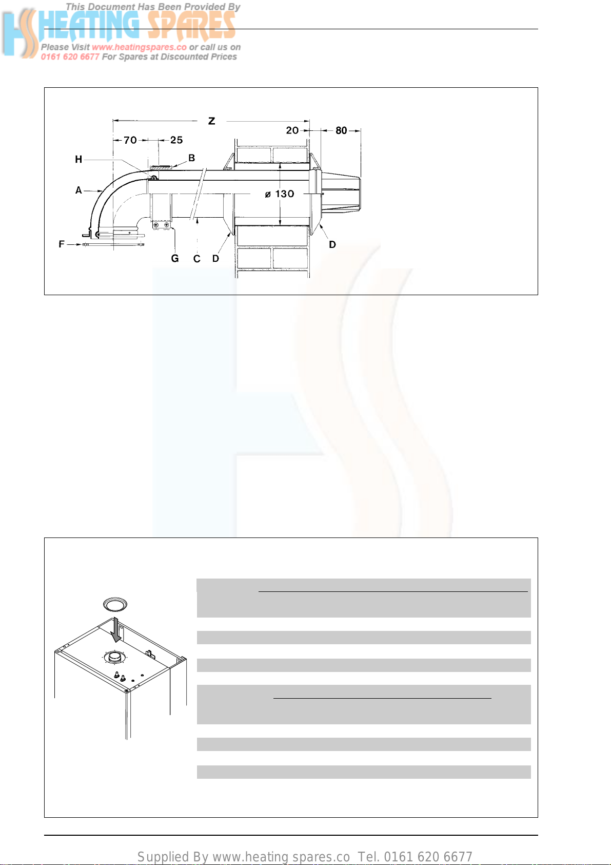
3.5.1 Coaxial duct diaphragm
The boiler is supplied with diaphragm to be used in relation
to the maximum horizontal or vertical lenght of the coaxial
duct and without additional elbows. See fig. 9 for positioning.
3.5.2 Installations from inside the room
Wall thickness up to 0.5 m [19 in] only, hole diameter 130
mm [19 in], sufficient to accept the optional wall liner kit.
– As previously detailed, a wall liner 129 mm diameter 500
mm [19 in] long is available as an optional extra for use when
fitting the flue air duct from inside the building, [or where it
is required to seal the hole through a cavity wall]. Cut the
liner to the wall thickness, insert into the hole, and seal with
mortar at inner and outer wall faces. Access to the outside
can be made by inserting one’s hand through the liner.
– Fit the rubber-sealing ring onto the largest diameter of the
plastic terminal as shown in fig. 8. Ensure that it is the correct way around and spray the outside surface with talcum
powder or soap solution to reduce friction.
– Remove the turret from the flue assembly.
– From inside the building slide the duct assembly into the
wall liner until the sealing ring passes completely through
the wall then pull the air duct back until the ring is pulled up
to the wall surface.
– Proceed to section 3.5.3.
3.5.3 Installations from outside the building only
– Fit the rubber-sealing ring onto the largest diameter of the
plastic terminal as shown in fig. 8. Ensure that it is the cor-
rect way around.
9
Fig. 8
Telescopic flue
KEY
AElbow
B Junction collar
C Outer duct
D Inner rubber sealing ring
F Neoprene gasket
G Protective metal collar
H Inner lip seal
NOTE: the kit can be extended to
a maximum measure of 580 mm
horizontal.
Fig. 9
TABLE 7
Horizontal coaxial duct lenght (Z fig. 8)
from 380 to 580 mm from 580 to 1500 mm from 1500 to 3000 mm
Standard diaphragm Optional diaphragm Diaphragm
Superior 40 Ci EI Ø 79 Ø 84 (Code 6028622) -
Superior 50 Ci EI Ø 81 Ø 84 (Code 6028622) -
Superior 60 Ci EI Ø 81 Ø 84 (Code 6028622) -
Superior 80 Ci EI Ø 84 Ø 87,5 (Code 6028624) -
Vertical coaxial duct lenght
from 1300 to 2500 mm from 2500 to 4000 mm
Standard diaphragm Optional diaphragm
Superior 40 Ci EI Ø 79 Ø 84 (Code 6028622)
Superior 50 Ci EI Ø 81 Ø 84 (Code 6028622)
Superior 60 Ci EI Ø 81 Ø 84 (Code 6028622)
Superior 80 Ci EI Ø 84 Ø 87,5 (Code 6028624)
Page 14
Supplied By www.heating spares.co Tel. 0161 620 6677
10
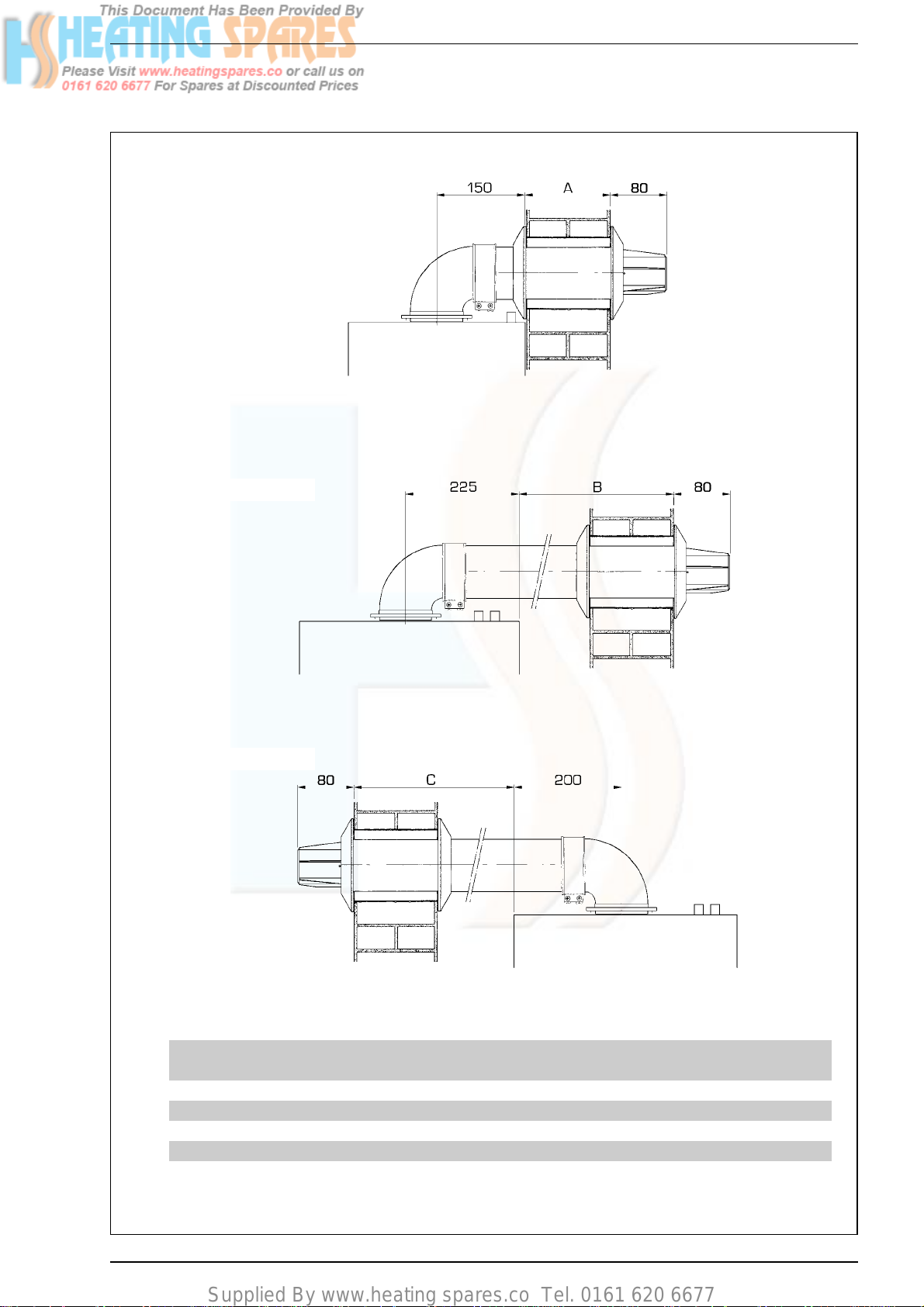
Fig. 10
REAR FLUE OUTLET
R.H. SIDE FLUE OUTLET
L.H. SIDE FLUE OUTLET
Telescopic flue
TABLE 8 - Maximum flue lengths (measured from appliance casing to outside wall face)
Rear outlet (A) R.H. side outlet (B) L.H. side outlet (C)
mm in mm in mm in
STANDARD FLUE KIT 425 16
3
/
4
350 13 3/
4
375 14 3/
4
WITH 1 EXTENSION KIT 1,245 49 1,170 46 1/
8
1,195 47
WITH 2 EXTENSION KITS 2,065 81
1
/
4
1,990 78 3/
8
2,015 79 3/
8
WITH 3 EXTENSION KITS 2,850 112 1/
4
2,775 109 1/
4
2,800 110 1/
4
NOTE: Extension kit cod. 8084804.
Page 15
Supplied By www.heating spares.co Tel. 0161 620 6677
11
– Remove the turret from the flue assembly.
– From outside the building, slide the duct assembly into the
wall until the sealing ring forms a good seal against the
outside wall.
3.5.4 Connecting the duct assembly
All installations
– From inside the building and with reference to fig. 8 slide
on the second rubber-sealing ring.
Check that the outer rubber-sealing ring is pulled up to the
wall and that the duct assembly is horizontal, and then
adjust the inner rubber-sealing ring to the correct position
to retain the flue assembly in position.
– Fit the two red ‘O’ rings into the grooves in each end of the
flue turret.
– Engage the flue turret into the air duct assemble, ensuring
the ‘O’ ring is correctly located and the air duct meets up
to the external swage on the turret.
– Secure together with the junction collar and clamp provided.
– Remove the five fixing screws securing the sealed cham-
ber front panel then remove the panel.
– Place the gasket under the flange of the elbow and fit the
elbow unto the top of the appliance, taking care to ensure
that the ‘O’ ring seal is correctly located. This must be
checked from inside the sealed chamber.
– Secure the elbow onto the top of the appliance using the
four screws provided.
– Refit the sealed chamber front panel.
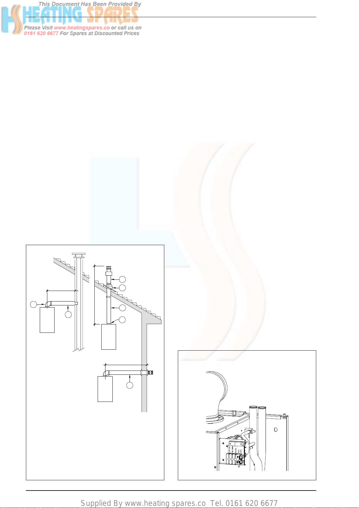
3.5.5 Coaxial flue outlets examples
The diagrams in fig. 11 illustrate a number of examples of different coaxial outlets
3.6 WATER CONNECTIONS
Detailed information is given in section 2.8. The appliance is
supplied with a flow and return pipe [each 22 mm copper] exiting the case at the top, rear right hand corner.
3.7 GAS CONNECTIONS
The gas service cock is located at the bottom right hand side
of the appliance. Connect the gas supply pipe to the Rc
1
/2”
connection using a suitable jointing compound.
The pipe should be routed to the rear of the appliance prior
to exiting downwards. This is to clear the decorative case. Fig.
16 shows the gas service cock.
3.8 WIRING INSTRUCTIONS
3.8.1 Boiler connections
The appliance electrical connections are situated at the top
right hand side. This is a covered and fused terminal block
with five connections. All installations require all connections
to be used (fig. 12).
Live This should be a permanent live supply to
the appliance
Earth
Neutral
Heat Demand This should be the switched live supply to
the appliance
Pump Live The live supply to the pump must be con-
nected to this.
ELECTRICAL CONNECTION BLOCK
Fig. 12
KEY
1 Coaxial flue kit code 8098601
2 Extension L. 820 code 8084804
4 90° curve code 8085603
5 Adapter code 8086901
6 Articulated tile code 8091300
7 Roof outlet terminal L. 1280 code 8091200
Fig. 11
IMPORTANT: Each additional 90° curve code 8085601
installed reduces the available length by 1.4 metres.
min 0,38 m
max 3 m
4
2
min 1,3 m - max 4 m
C42
7
6
2
5
C32
min 0,38 m
max 3 m
C12
1
Page 16
Supplied By www.heating spares.co Tel. 0161 620 6677
12
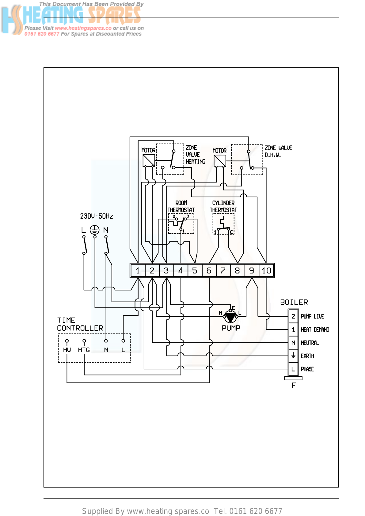
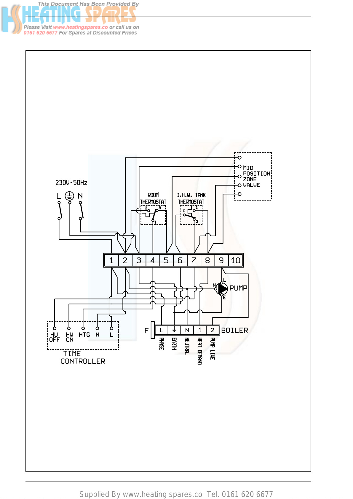
3.8.2 Schematic system wiring diagrams
Fig. 14
FULLY PUMPED SYSTEM USING TWO ZONE VALVES
Page 17
Supplied By www.heating spares.co Tel. 0161 620 6677
13
Fig. 15
FULLY PUMPED SYSTEM USING MID POSITION ZONE VALVE
Page 18
Supplied By www.heating spares.co Tel. 0161 620 6677
14
SIME SUPPORT THE BENCHMARK INITIATIVE
All relevant sections of the logbook must be filled in at the
time of installation and thereafter service information on the
back page of the logbook. Commissioning of the boiler is not
complete until the logbook is filled in.
Before commissioning the appliance, the whole gas installation including the meter MUST be purged and tested for gas
soundness in accordance with BS6891.
IMPORTANT: open all doors and windows, extinguish naked
lights, and DO NOT SMOKE whilst purging the gas line.
Before commencing the commissioning procedure, ensure
that the electricity supply is isolated and the gas service cock
is turned on.
4.1 INITIAL WATER FILL AND
LIGHTING THE APPLIANCE
– Open all the valves in the system and ensure the system
and boiler are thoroughly flushed.
–
Refill and vent the complete system and boiler and check for
water leaks. Ensure all valves are open to complete this.
– Connect a suitable pressure test gauge to the test point,
located on the gas valve.
– Set all external controls to on and turn on the electrical supply.
– Turn the boiler control to maximum and check the pump is
operating correctly and water is circulating.
– After a short period the ignition lockout indicator will be illumi-
nated, Press the reset button and turn off the boiler control.
– Turn on the gas supply.
– Turn the boiler control to maximum and check the boiler lights.
– Allow the boiler to operate for at least 2 minutes and
check the burner pressure is in accordance with that spe-
cified on the data label.
–
If adjustment is required, remove the cover from the top
of the governor on the gas valve and adjust the burner
pressure.
– Replace the cover and turn off the appliance.
– Remove the pressure test gauge and refit the sealing
screw. Check for gas soundness with leak detection fluid.
– Make sure the external controls are fully operational and
the complete system is controlled correctly. Balance the
flow rates through the boiler, radiators and hot water tank.
The complete system should now be allowed to heat to
maximum and a final check completed.
– Turn off the system and drain for the final time.
– Refill and vent the system completely.
– Set the boiler and external controls to a suitable setting.
4.2 ADDITIONAL OPERATIONS
FOR SEALED SYSTEMS
Whilst the system is empty and cold, check the expansion
valve is pre-charged to the desired pressure. This can be
done using a tyre pressure gauge. Increase or reduce the
pre-charge as required.
Following the Hot drain down, flush the system thoroughly and
refill the system to a pressure of 1.5 bar.
Check the operation of the safety valve and check for leaks.
Whilst still cold, adjust the system pressure to that required.
Set the pointer on the gauge to indicate the set pressure.
4.3 FINAL CHECKS
– Re-light and test for gas soundness.
– Re-fit the white outer casing and secure it at the bottom
with the two screws provided.
4.4 USER’S INSTRUCTIONS
Upon completion of commissioning and testing the system,
the installer should:
–
Give the ‘Users instructions’ to the householder and empha-
sise their responsibilities under the Gas Safety [Installation
and Use] Regulations 1998 (as amended] Explain and
demonstrate the lighting and shutdown procedures.
– Advise the householder on the efficient use of the system,
including the use and adjustment of all system controls.
– Advise the user of the precautions necessary to prevent
damage to the system, and to the building, in the event of
the system remaining inoperative during frost conditions.
– Explain the function of the boiler overheat control, and how
to reset it.
– Emphasise that if cut out persists, the boiler should be tur-
ned off and the installer or service engineer consulted.
– Stress the importance of an annual service, by a regular
heating engineer.
4 COMMISSIONING AND TESTING
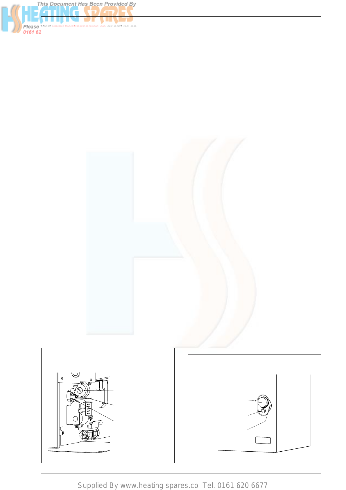
Fig. 16
GAS VALVE SHOWING GAS PRESSURE TEST POINT,
ADJUSTER AND GAS COCK
APPLIANCE CONTROLS
Fig. 17
BURNER PRESSURE ADJUSTER
OUTLET GAS PRESSURE
TEST POINT
INLET GAS PRESSURE
TEST POINT
GAS COCK
IGNITION AND
TEMPERATURE CONTROL
LOCK-OUT BUTTON
OVERHEAT WARNING LAMP
Page 19

Supplied By www.heating spares.co Tel. 0161 620 6677
15
To ensure continued efficient operation of the appliance, it is
recommended that it is checked and serviced as necessary
at regular intervals.
The frequency of servicing will depend upon the particular
installation conditions and usage but in general once a year
should be adequate. It is the law that any service work must
be carried out by registered personnel [C.O.R.G.I.].
Before commencing any service operation, ISOLATE the
mains electrical supply, and TURN OFF the gas supply at the
main service cock. Service the appliance by following the full
procedure detailed below.
A flue products sampling point is located to the right hand
side of the appliance.
This may be used to check the performance of the appliance
prior to/instead of servicing.
It is the lower of the two fittings to which the air pressure switch is connected. The test equipment should be connected but
not switched on before the appliance is in operation.
5.1 MAIN BURNER ASSEMBLY
–
Remove the casing by unscrewing the retaining
screws at bottom rear of the appliance and pulling the
panel forwards, lifting it off the two pins at the top two
corners
.
– Remove the 4 fixing screws securing the sealed chamber
front panel then remove the panel.
– Unscrew the 2 screws securing the combustion chamber
front panel and remove the panel, taking care not to damage the insulation.
– Remove the red ignition control box from the gas valve, 1
screw.
– Unplug the ignition and detection leads from the ignition
box, taking note of their respective position.
–
Slide the burner forwards and at the same time feed the
two wires through the grommet in the sealed chamber.
Remove the burner complete with the electrodes and leads.
– Inspect and if necessary clean the electrodes and the main
burner bars.
– Inspect the main injector for any signs of damage or debris
and clean if necessary.
5.2 FAN ASSEMBLY
– Disconnect the electrical connections to the fan. Note the
position of the earth conductor.
– Whilst supporting the fan, remove the three screws secu-
ring the fan to the mounting plate.
– Slide the fan downwards and once disengaged from the
flue turret, remove it forwards
– Inspect the fan and clean if necessary.
5.3 HEAT EXCHANGER
– Remove the fan mounting plate, 2 screws.
– Remove each of the flue baffles by lifting them upwards,
clear of the heat exchanger and clean if necessary.
– Inspect the heat exchanger and clean if necessary with a
soft brush.
5.4 RE-ASSEMBLY
– Re-assemble all the components in reverse order.
– Check that the fan earth connection is correctly re-fitted.
Note that the fan polarity [Line and Neutral] is immaterial.
– Ensure the ignition wires are correctly fitted and connec-
ted to the ignition control
– Ensure that all seals are correctly fitted.
– Fit the sealed chamber front panel
– Check for gas soundness before fitting the white casing.
5.5 RE-COMMISSIONING
– Turn on the gas supply, and check for gas soundness.
– Check the operation of the appliance and all the external
controls.
– The burner pressure should be checked after at least 10
minutes running. The data label on the appliance states
the details.
– Adjust if necessary as described in section 4.
5 ROUTINE SERVICING INSTRUCTIONS
Page 20
Supplied By www.heating spares.co Tel. 0161 620 6677
16
If an electrical fault occurs on the appliance the preliminary
electrical system checks contained in the British Gas Multimeter Instruction Booklet must be carried out first.
When any service or replacement of electrical components
which has required the breaking and re-making of electrical
connections has taken place, the following tests must be
repeated:
– Earth continuity
– Short circuit
– Polarity
– Resistance to earth
6.1 EARTH CONTINUIT Y CHECK
Appliances must be electrically disconnected the meter set
on Ω [ohm] x 1 scale and adjust the zero if necessary. Tests
leads from any appliance earth point [e.g. inside control box]
see wiring diagrams [section 7] to earth pin on the plug or
mains inlet point. Resistance should be less than 1Ω [ohm]. If
turn resistance is greater than 1Ω [ohm], check all earth
wires for continuity and all contacts are clean and tight. If the
resistance to earth is still greater than 1Ω [ohm] then this
should be investigated further.
6.2 SHORT CIRCUIT CHECK
Switches turned FULL ON meter set on Ω [ohm] x 1 scale and
adjust the zero if necessary. Test leads from L to N on appliance terminal block, if meter reads 0 then there is a shout circuit.
Meters set on Ω [ohm] x 100 scale and adjust the zero if
necessary. Repeat it with leads from L to E. If meter reads
less than infinity [∞] there is a fault.
NOTE: Should it be found that the fuse has failed but no
fault is indicated, a detailed continuity check [i.e. by disconnecting and checking each component] is required to trace
the faulty component.
It is possible that a fault could occur as a result of local burning/arcing but no fault could be found under test. However,
a detailed visual inspection should reveal evidence of burning
around the fault.
6.3 POLARITY CHECK
Appliance reconnected to mains supply and meter set on
300 V ac scale. Test at appliance terminal block:
– Test leads from L to N meter reads approx. 230 V ac.
– Test leads from L to E meter reads approx. 230 V ac.
– Test leads from N to E meter reads from 0 to 15 V ac.
6.4 RESISTANCE TO EARTH CHECK
Appliance must be disconnected from main supply and meter
set on Ω [ohm] x 100 scale and adjust the zero if necessary.
All switches including thermostat on test leads from L to E –
if meter reads other than infinity [∞] there us a fault, which
should be isolated. A detailed continuity check is required to
trace the faulty component.
IMPORTANT: These series of checks are the first electrical
checks to be carried out during a faultfinding procedure.
On completion of the service/fault finding task which has
required the breaking and remaking of electrical connections then the checks 6.1 Earth continuity, 6.3 Polarity and
6.4 Resistance to earth must be repeated.
6 FAULT FINDING
Page 21
Supplied By www.heating spares.co Tel. 0161 620 6677
17
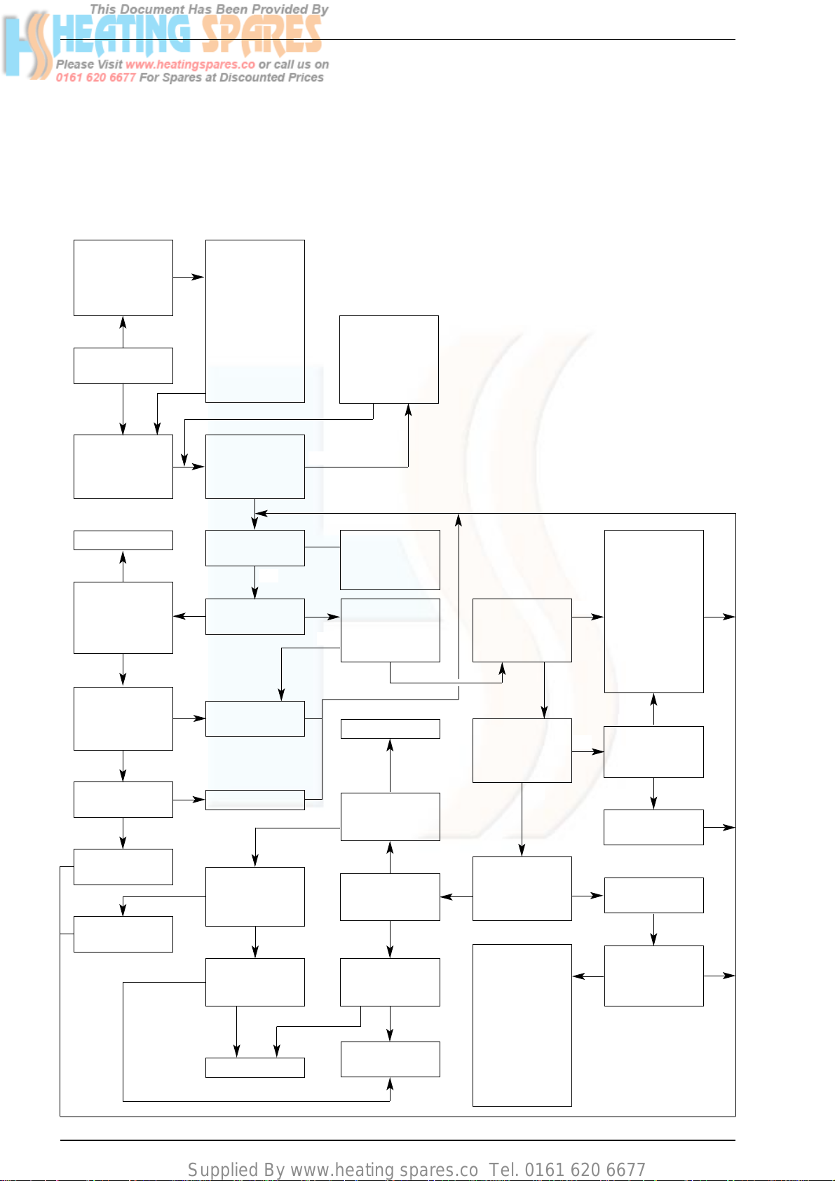
6.5 FAULT FINDING
Before proceeding through this fault finding guide:
1) ensure all connections to the electronic circuit board
and the 12 way connector to the ignition device are correctly fitted.
2) Position the temperature control completely anticlockwise.
3) Turn ON external gas and electricity supplies.
4) Ensure there is 230 V at the permanent live “PHASE” on
the installation terminal block.
5) Ensure there is 230 V at the switched live “HEAT
DEMAND” on the installation terminal block. A link between
terminals “PHASE” and “HEAT DEMAND” will simulate the
external controls being ON.
NOTE: A 3 minutes anti-cycle device is
incorporated in the boiler control
Is the overheat LED
illuminated?
Switch off the
permanent supply to
terminal “L” for 5
seconds minimum
then back on
The LED will now
be out. Investigate
the cause of the
overheat situation
and rectify
Possible cause:
Lack of water
Lack of water flow
Faulty overheat stat
Faulty thermistor
Faulty PCB
Is there 10 Vdc or
1 Vdc at terminal 1
of the ignition control
connection
Is the ignition Lockout neon illuminated
Does the fan start
to run
Turn the
temperature control
knob to ignite
the boiler
Replace the fan
Yes
1 Vdc
No
Is there 230 V at
terminal 8 on the
ignition control
connection
Yes
No
Is there 230 V at
terminal 6 on the
ignition control
connection
No
Yes
Yes
Yes
No
No
Yes
Fault
Fault
Satisfactory
Does the gas valve
open and allow gas
to the main burner
injector
Is there a spark
between the ignitor
and the burner
Yes
Operation normal
Replace assembly
Yes
Is there 230 V at the
fan motor
Yes
Check the wiring and
rectify
No
Check the spark gap
and rectify
No
No
No
Disconnect fan leads
from fan motor.
Is there between
30 - 60 ohms across
fan motor?
Replace the ignition
device
No
Replace the fan
Yes
Satisfactory
The termistor
potentiometer
or PCB is faulty
replace each in turn
separately to find
and rectify the fault
Allow 10 seconds
minimum then
depress the ignition
reset button
Yes
Is there 230 V at
terminal 7 on the
ignition control
connection
Does the boiler ignit e
and continue to
operate satisfactorily
Does the burner
ignite and extinguish
after approximately
10 seconds
Yes
Is there 230 V at
terminal 5 on the
ignition control
connection
Yes
No
No
Is there 230 V at
terminal N/O on the
air pressure switch
No
Replace the ignition
device
Replace the ignition
device
Check the
condition of the flame
sensor and its lead
Check the condition
of the electrode
and its lead
Replace the overheat
thermostat
Does the gas valve
open and allow gas
to the main burner
injector
Yes
Air pressure switch
has not changed
over, investigate
and rectify
Possible cause:
Air pressure switch
faulty
Fan performance
poor
Flue/Air duct
blocked
Check the
adjustment of
the gas valve.
If this does not rectify
the fault replace the
gas valve.
The original
ignition device should
be used
on the new valve.
It is unlikely both will
be fault
No
Page 22
Supplied By www.heating spares.co Tel. 0161 620 6677
18
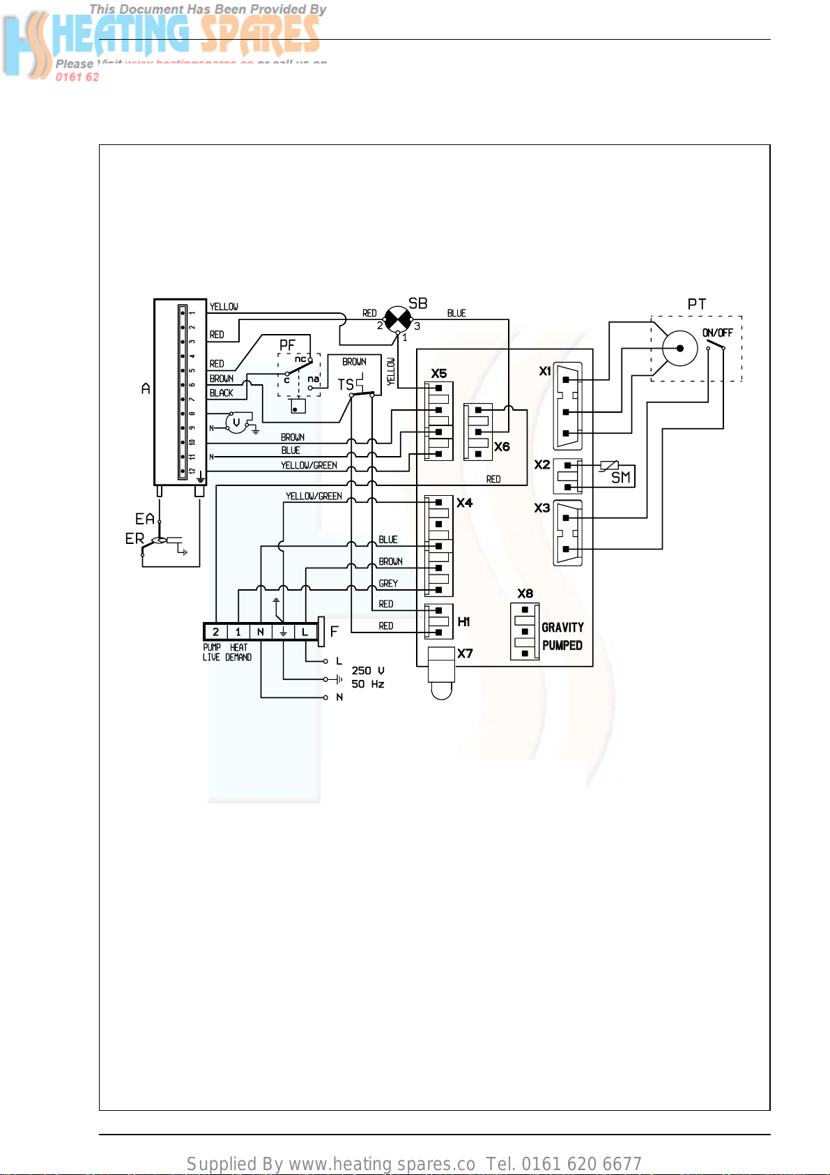
7 WIRING DIAGRAM AND INTERNAL VIEW
7.1 FUNCTIONAL FLOW WIRING DIAGRAM
KEY
L Phase
N Neutral
F Fuse F2A
EA Ignition electrode
ER Ionisation probe
A Control box Honeywell S4565CF
TS H.L. stat
PF Smoke pressure switch
VFan
SM Outlet temperature sensor
PT Potentiometer/on-off switch
SB Ignition reset button and lockout indicator
Fig. 18
Page 23
Supplied By www.heating spares.co Tel. 0161 620 6677
19
3
4 6
7
1
8
5
2
9
16
10
11
12
13
14
15
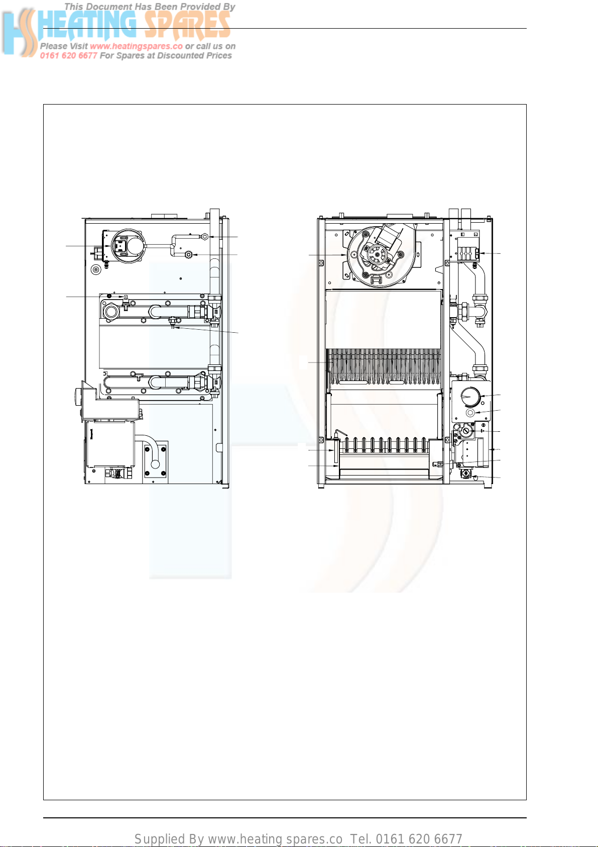
7.2 INTERNAL VIEW
Fig. 19
KEY
1 Igniter P.CB.
2 Safety stat 105°C
3 Air pressure switch
4 Positive pressure test point
5 Negative pressure test point
6 Thermistor
7 Pumped/gravity switch
8 Main burner assembly
9 Ignition electrode/ionisation probe
10 Cast-iron exchanger
11 F a n
12 On/Off switch - Potentiometer
13 Lock-out button
14 Gas valve
15 Main gas nozzle
16 Gas cock
17 Terminal strip
Page 24
Supplied By www.heating spares.co Tel. 0161 620 6677
Before commencing any service operation, ISOLATE the
mains electrical supply, and TURN OFF the gas supply at the
main service cock. It is the law that any service work must be
carried out by registered personnel [C.O.R.G.I.].
Following the replacement of any components the appliance
should be re-commissioned as detailed in section 4.
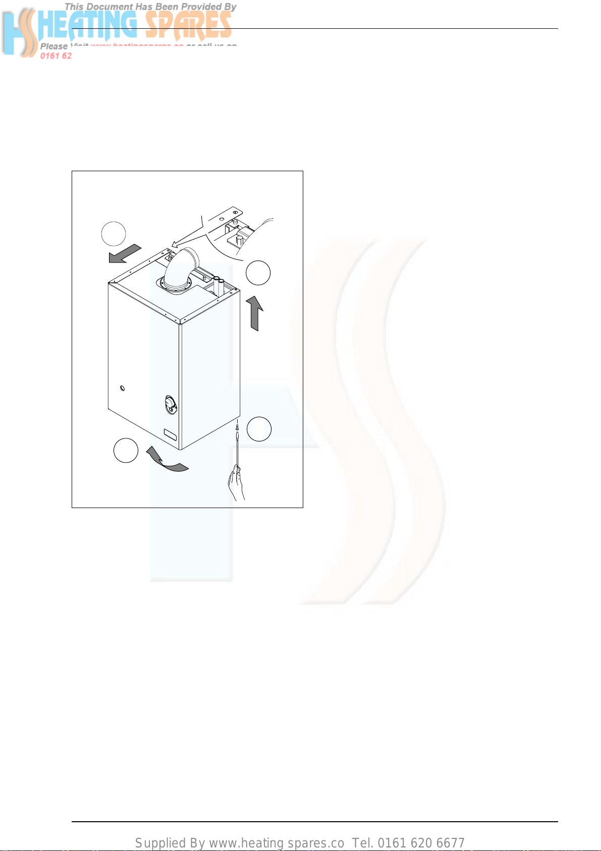
8.1 AIR PRESSURE SWITCH
– Remove the casing by unscrewing the retaining screws at
bottom rear of the appliance and pulling the panel
forwards, lifting it off the two pins at the top two corners.
– Disconnect the three wires from the air pressure switch,
noting their position.
– Pull of f the two sensing tubes.
– Unscrew the two screws retaining the air pressure switch
and its bracket and remove the assembly.
– Remove the air pressure switch from its mounting
bracket, 2 screws.
– Replace the air pressure switch and re-assemble in rever-
se order. Ensure the sensing tubes and electrical connec-
tions are correctly fitted.
8.2 LIMIT THERMOSTAT
– Remove the casing by unscrewing the retaining screws at
bottom rear of the appliance and pulling the panel
forwards, lifting it off the two pins at the top two corners.
– Disconnect the two wires from the thermostat.
– Unscrew the thermostat from the manifold.
– Replace the thermostat and re-assemble in reverse order.
8.3 CONTROL TEMPERATURE SENSOR
– Remove the casing by unscrewing the retaining screws at
bottom rear of the appliance and pulling the panel
forwards, lifting it off the two pins at the top two corners.
– Disconnect the two wires from the control sensor.
– Unscrew the control sensor from the manifold.
– Replace the control sensor and re-assemble in reverse
order.
8.4 IGNITION CONTROL BOX
– Remove the casing by unscrewing the retaining screws at
bottom rear of the appliance and pulling the panel
forwards, lifting it off the two pins at the top two corners.
– Unscrew the screw retaining the cover of the control box,
unplug the connector and remove the control box.
– Replace it and re-assemble in reverse order.
8.5 ELECTRONIC PCB
– Remove the casing by unscrewing the retaining screws at
bottom rear of the appliance and pulling the panel
forwards, lifting it off the two pins at the top two corners.
– Remove the cover of the control panel by unscrewing the
rear screw, lift it off the two front pins and turn upside-
down to gain access to the electronic PCB.
– Unplug the connectors and remove the PCB by
unscrewing the retaining screws.
– Replace the electronic PCB and re-assemble in reverse
order.
8.6 GAS VALVE
– Remove the casing by unscrewing the retaining screws at
bottom rear of the appliance and pulling the panel
forwards, lifting it off the two pins at the top two corners.
– Remove the cover of the control panel by unscrewing the
rear screw, lift it off the two front pins to gain access to
the screws blocking the lower support of the control panel;
unscrew them to remove the control panel.
– Remove the ignition control box from the gas valve, 1
screw.
– Close the gas cock under the gas valve; disconnect it from
the valve (4 screws) and disconnect the pipe connecting
the gas valve to the sealed chamber (4 screws).
– Replace the gas valve and re-assemle in reverse order.
8.7 MAIN BURNER
– Remove the casing by unscrewing the retaining screws at
bottom rear of the appliance and pulling the panel
forwards, lifting it off the two pins at the top two corners.
– Remove the 4 fixing screws securing the sealed chamber
front panel then remove the panel.
– Unscrew the 2 screws securing the combustion chamber
front panel and remove the panel, taking care not to dama-
ge the insulation.
– Remove the red ignition control box from the gas valve, 1
screw.
– Unplug the ignition and detection leads from the ignition
20
8 REPLACEMENT OF PARTS
Fig. 20
1
2
4
3
HOW TO REMOVE THE CASING
Page 25
Supplied By www.heating spares.co Tel. 0161 620 6677
21
box, taking note of their respective position.
– Slide the burner forwards and at the same time feed the
two wires through the grommet in the sealed chamber.
Remove the burner complete with the electrodes and
leads.
– Unscrew and remove each electrode
– Fit the existing electrodes to the new burner, ensuring
their correct position.
– Re-assemble all the components in reverse order.
8.8 IGNITION ELECTRODE
– Remove the ignition electrode [front] as detailed in section
8.7.
– Replace the ignition electrode and re-assemble in reverse
order.
8.9 DETECTION ELECTRODE
– Remove the detection electrode [front] as detailed in sec-
tion 8.7.
– Replace the detection electrode and re-assemble in rever-
se order.
8.10 MAIN BURNER INJECTOR
– Remove the main burner as detailed in section 8.7, without
removing the electrodes from the burner
– Unscrew and remove the injector from the gas manifold,
working from within the sealed chamber.
– Replace the injector and re-assemble in reverse order.
8.11 COMBUSTION FAN
–
Remove the casing by unscrewing the retaining
screws at bottom rear of the appliance and pulling the
panel forwards, lifting it off the two pins at the top two
corners.
– Remove the 4 fixing screws securing the sealed chamber
front panel then remove the panel.
– Unscrew the 2 screws securing the combustion chamber
front panel and remove the panel, taking care not to damage the insulation.
– Disconnect the electrical connections to the fan. Note the
position of the earth conductor.
– Whilst supporting the fan, remove the three screws secu-
ring the fan to the mounting plate.
– Slide the fan downwards and once disengaged from the
flue turret, remove it forwards.
– Replace the fan and re-assemble in reverse order.
8.12 BURNER VIEWING WINDOW
– Remove the casing by unscrewing the retaining screws at
bottom rear of the appliance and pulling the panel
forwards, lifting it off the two pins at the top two corners.
– Remove the 4 fixing screws securing the sealed chamber
front panel then remove the panel.
– Push out the broken viewing window from the inside if the
front panel.
– Remove all debris from the retaining seal.
– Replace the viewing window and re-assemble in reverse
order.
8.13 COMBUSTION CHAMBER INSULATION
The design of this appliance is such that the rear insulation
panels do not normally require replacement unless mechanically damaged.
IMPORTANT:
When handling insulation panels, take care to avoid producing or inhaling dust particles. When removing old panels.
Dampen with water to minimise dust.
– Remove the casing by unscrewing the retaining screws at
bottom rear of the appliance and pulling the panel
forwards, lifting it off the two pins at the top two corners.
– Remove the 4 fixing screws securing the sealed chamber
front panel then remove the panel.
– Unscrew the 2 screws securing the combustion chamber
front panel and remove the panel.
– Replace the front panel insulation panel.
– The side insulation panels may be replaced by sliding them
forwards, clear of their retaining metalwork.
– Re-assemble the components in reverse order. If the rear
insulation panels are to be removed, the fan, fan mounting
plate, heat exchanger baffles and air pressure sensing
probe should be removed first.
– The rear panels can now be removed.
– Replace, fitting the lower piece from the bottom and the
upper two from the top.
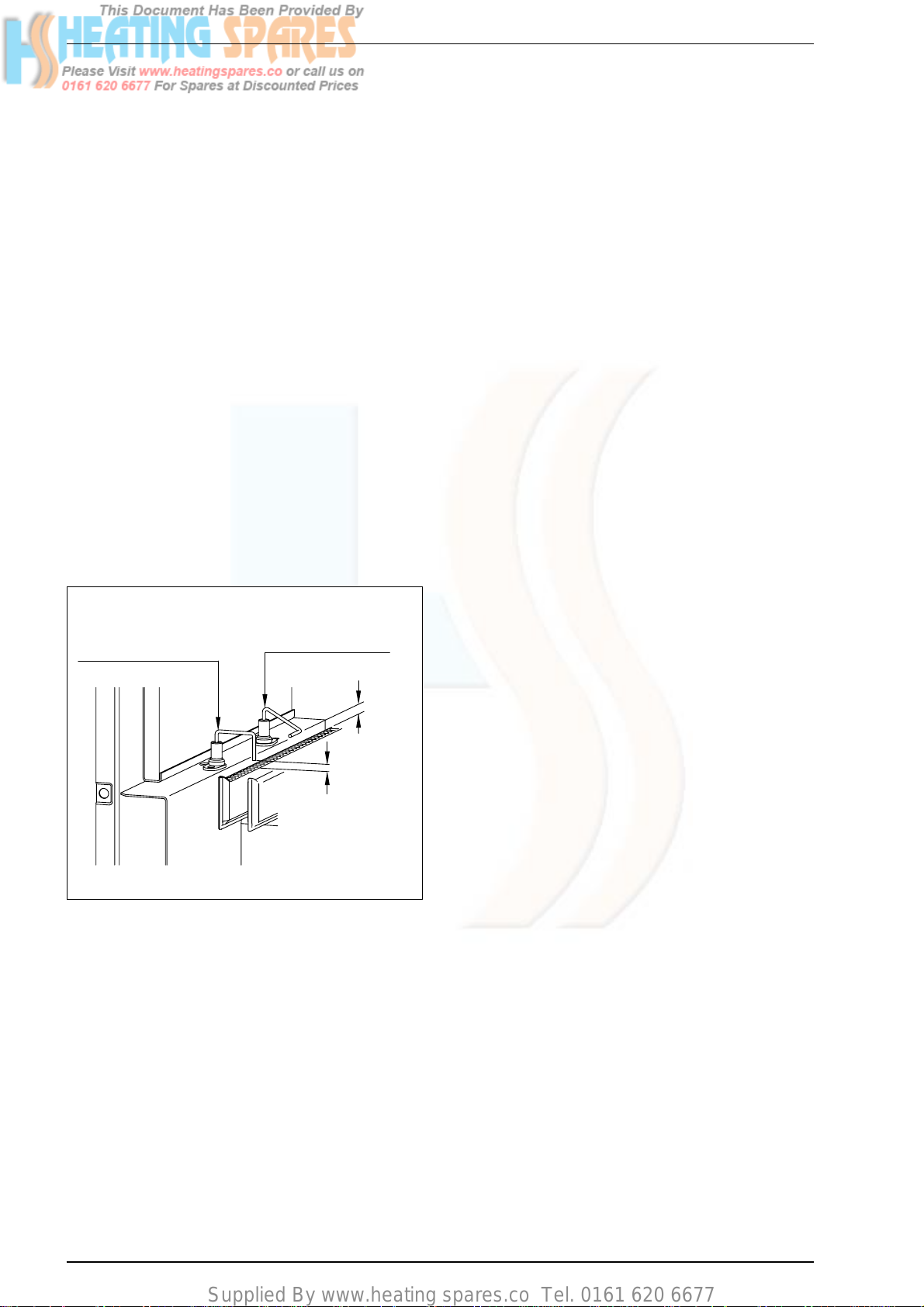
IGNITION & DETECTION ELECTRODE POSITIONS
Fig. 21
IGNITION ELECTRODE
IONISATION PROBE
7,5 ±0,5
3,5 ±0,5
Page 26
Supplied By www.heating spares.co Tel. 0161 620 6677
22
9 EXPLODED VIEWS
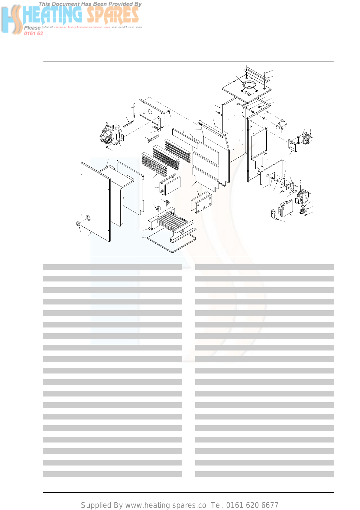
9.1 COMBUSTION CIRCUIT
3
4
11
75
74
1059
6
60
2
32
8
1
58
59
56
57
7
55
14
16
33
34
16
15
2
35
40 41
29
13
19
19
13
17
18
36
39
38
46
50
49
51
54
53
45
42
52
44
48
47
82
43
37
Fig. 22
Position Code Description Model
1 6266050 Sealed chamber rear panel 40-50-60
1 A 6266052 Sealed chamber rear panel 80
2 • 2013302 Fastener for self tapping screw
3 6247700 Three ways junction
4 6235801 Pressure test nipple M6
5 6168802 Junction 1/8”
6 6246310 Sealed chamber upper panel 40-50-60
6 A 6246311 Sealed chamber upper panel 80
7 6246210 Sealed chamber lower panel 40-50-60
7 A 6246211 Sealed chamber lower panel 80
8 6285300 Sealed chamber rear panel 40-50-60
8 A 6285301 Sealed chamber rear panel 80
9 6009579 Intake pipe fixing bracket
10 6263904 Air intake pipe
11 6146303 Brass Nut 1/8”
13 6285400 Combustion chamber side panel 40-50-60
13 A 6285401 Combustion chamber side panel 80
14 6285501 Fan plate rear left angle bar
15 6285500 Fan plate rear right angle bar
16 6285502
Comb. chamber door suppor t. angle bar
40-50-60
16 A 6285503
Comb. chamber door suppor t. angle bar
80
17 613 9 76 4
Combustion chamber rear lower insul.
40-50-60
17 A 613 97 6 8
Combustion chamber rear lower insul.
80
18 613 9 76 5
Combustion chamber rear insulation
19 613 9 76 6
Combustion chamber side insulation
40-50-60
19 A 6139767 Combustion chamber side insulation 80
29 6285810 Baffle for cast iron section
32 2005000 Self threading screw Hex.H. M5x10
33 6229213 Fan mounting plate 40-50
33 A 6229215 Fan mounting plate 60
33 B 6229214 Fan mounting plate 80
34 2016020 Locked nut M4
35 • 6225617 Fan 40-50
35 A • 6225618 Fan 60
35 B • 6225619 Fan 80
36 2000705 Screw M4x12
37 6229103 Terminal strip bracket
Position Code Description Model
38 6229101 Smoke pressure switch bracket
39 • 6225713 Air pressure switch 40-50
39 A • 6225715 Air pressure switch 60-80
40 6285600 Combustion chamber front panel 40-50-60
40 A 6285602 Combustion chamber front panel 80
41 613 97 78
Combustion chamber front insulation
42 6286300 Gas manifold 40-50-60
42 A 6286301 Gas manifold 80
43 6050265 Nozzle Ø 3,25 40-50
43 A 6050232 Nozzle Ø 3,55 60
43 B 6050286 Nozzle Ø 4,10 80
44 6022001 Aluminium washer Ø 10
45 6283908 Sealed chamber side insulation 40-50-60
45 A 6283909 Sealed chamber side insulation 80
46 • 6243815 Honeywell gas valve type VK4105C
47 6226429 O-ring 121
48 • 2000702 Screw TCB M5x8 ZnCr
49 • 6177580 Angle ball cock
50 • 6226407 O-ring 130 ø 22,22x2,62 XP70
51 2000203 Screw TCEI M4x12
52 6162411 Gasket for gas manifold
53 6210207 Control box Honeywell S4565CF1086
54 6174504 Honeywell control box cover
55 5189801 Main burner 40-50-60
55 A 5189802 Main burner 80
56 • 6235926 Ignition electrode
57 • 6235925 Ionisation electrode
58 6285700 Sealed chamber door 40-50-60
58 A 6285703 Sealed chamber door 80
59 6001210 Peephole
60 6028621 Air diaphragm Ø 79 40
60 A 6028620 Air diaphragm Ø 81 50-60
60 B 6028622 Air diaphragm Ø 84 80
74 6285504 Sealed chamber upper fixing bracket
75 6242603 Screw M6x1
82 6041110 Rear deflector
• Recommended stock parts
Page 27
Supplied By www.heating spares.co Tel. 0161 620 6677
23
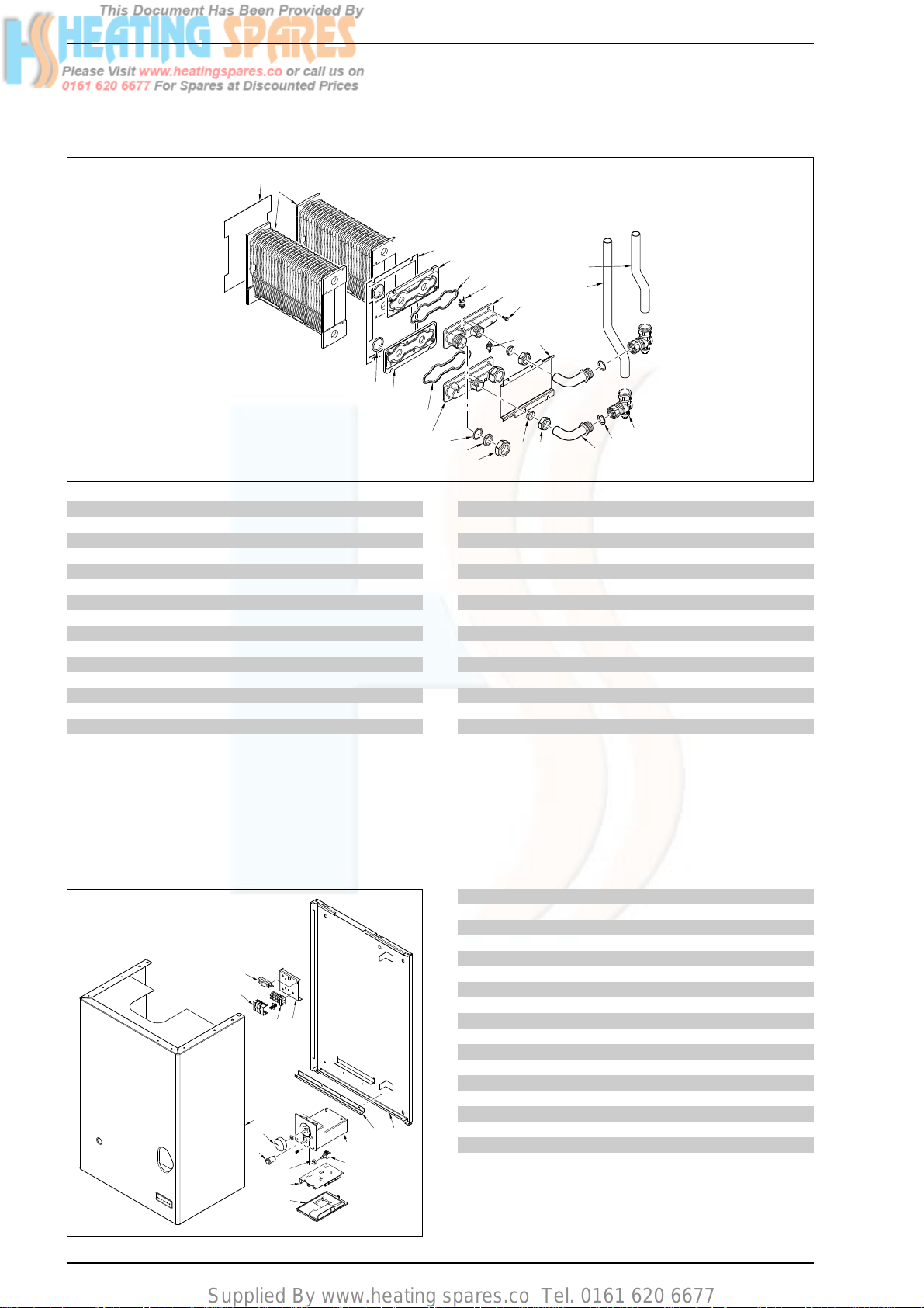
9.2 HYDRAULIC CIRCUIT
26
21
25
20
25
30
31
24
81
22
27
28
86
78
79
76
77
85
23
68
68
84
83
86
Fig. 22/a
Position Code Description Model
20 6286102 Cast iron exchanger
21 6291300 Flow manifold 40-50-60
21 A 6291301 Flow manifold 80
22 6291320 Return manifold 40-50-60
22 A 6291321 Return manifold 80
23 • 6226431 O-ring 4125
24 6285902 Manifold fixing plate 40-50-60
24 A 6285903 Manifold fixing plate 80
25 6174850 Gasket for cast iron section 40-50-60
25 A 6174851 Gasket for cast iron section 80
26 2000580 Screw Hex. H. M5x16
27 6226433 O-ring ø 27x2
28 6229513 Locking nut 1-3/8”
30 • 6146716 105°C safety stat
31 • 6231354 Plunged sensor
Position Code Description Model
68 6291400 Manifold flange 40-50-60
68 A 6291401 Manifold flange 80
76 6289723 Lower inlet pipe
77 6289722 Upper inlet pipe
78 • 6100203 Copper ogive for pipe Ø 22 mm
79 6229512 Locking nut 1-1/8”
81 6100204 Ogive for pipe Ø 28
83 6177505 Ball cock 3/4” x 22
84 2030228 Gasket Ø 17x24x2
85 6289720 Pipe connecting manifold-cock 40-50-60
85 A 6289721 Pipe connecting manifold-cock 80
86 6291500 Gasket for manifold flange 40-50-60
86 A 6291501 Gasket for manifold flange 80
• Recommended stock parts
Position Code Description Model
37 6229103 Terminal strip bracket
61 6286901 Control panel lower part
62 6286801 Control panel
63 • 6230640 Control board
64 2213201 Spacer Ø 15x5
65 • 6278657 Potentiometer c/w cable connector
66 • 6070410 Red pushing button
67 6230921 Knob Ø 40
69 6145050 Terminal strip
70 6145004 Terminal strip cover
71 2214200 Cable clamp
72 6287000 Frame rear par t
73 6009584
Sealed chamber supporting bracket
40-50-60
80 5191300 Casing 40-50-60
80 A 5191301 Casing 80
• Recommended stock parts
73 72
80
71
70
67
62
66
63
64
61
65
69
37
9.3 STRUCTURAL COMPONENTS AND CONTROL & REGULATIONS
Fig. 22/b
Page 28
Supplied By www.heating spares.co Tel. 0161 620 6677
24
USER INSTRUCTIONS
VERY IMPORTANT!
PLEASE MAKE SURE YOUR LOG BOOK ENCLOSED IS FILLED IN CORRECTLY.
ALL CORGI REGISTERED INSTALLERS CARRY A CORGI ID CARD.
BOTH SHOULD BE RECORDED IN YOUR CENTRAL HEATING LOG BOOK.
YOU CAN CHECK YOUR INSTALLER IS CORGI REGISTERED
BY CALLING ON 01256 372300
GAS SAFETY [INSTALLATION AND USE] REGULATIONS [as
amended]. It is the law that a registered person, in accordance with the above regulations, installs all gas appliances.
Failure to install appliances correctly could lead to prosecution. It is in your own interest, and that of safety, to ensure
that the law is complied with.
It is essential that the appliance be correctly earthed.
An electricity supply of 230 V~ 50 Hz fused at 3 A is
required.
Read these instructions carefully before attempting to operate the appliance.
1.1 INTRODUCTION
The Sime “Superior Ci EI” are a range of wall mounted cast
iron boilers. They utilise a fully automatic ignition system
together with electronic temperature control. The combustion system is fan assisted and uses a concentric flue and air
duct that can exit the boiler to either side or to the rear, ending in a small balanced flue terminal on the outside wall.
The appliance is suitable for use with natural gas.
1.2 APPLIANCE OPERATION
The installation engineer will have set the range rated appliance to the correct heating requirement for the property.
There should be no need to adjust the boiler control once it
has been set unless the temperature set point needs to be
increased or decreased. The thermostat knob will adjust the
set point temperature of the electronic controls in the appliance. Turning clockwise increases the set point.
A demand for heat from the external controls will:
– check the air pressure switch,
– start the fan,
– confirm correct air flow through the appliance,
– start the spark generator,
– open the gas valve,
– ignite and prove the flame,
– monitor the appliance flow temperature, switching the
appliance on and off as necessary.
– should the appliance fail to light, the lockout button will illu-
minate.
1.3 OPERATING INSTRUCTIONS
1.3.1 To light the appliance
– Turn on the electrical supply and set all external controls
to on.
– Turn the boiler control to maximum and check the pump is
operating correctly and water is circulating.
– After a shor t period the ignition lockout indicator will be illu-
minated, after a 10 second wait depress the lockout button
to reset the ignition sequence. Turn off the boiler control.
OPERATING INSTRUCTIONS FOR THE USER
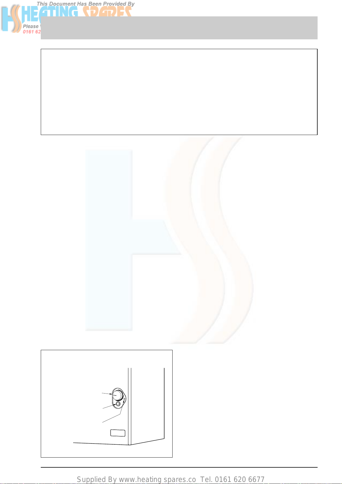
APPLIANCE CONTROLS
TEMPERATURE CONTROL
IGNITION AND
LOCK-OUT BUTTON
OVERHEAT WARNING LAMP
Page 29
Supplied By www.heating spares.co Tel. 0161 620 6677
25
– Turn on the gas supply.
– Turn the boiler control on, and to maximum. Check the
boiler lights.
– Set the boiler control to the required temperature for the
maximum boiler flow. Turning clockwise increases the set
point temperature.
– Make sure the external controls are fully operational and
the complete system is controlled correctly.
1.3.2 To turn the appliance off
The appliance may need to be switched off for short periods.
If required the boiler control may be rotated to the ‘OFF’ position (completely anti clock wise) which will prevent the appliance from operating in the event of a demand from any external controls.
If the appliance is to be switched off for long periods the boiler control should be rotated to ‘OFF’ and the electrical supply
to the complete system should be isolated.
If the appliance is to be switched off for a prolonged length of
time during severe cold conditions then it is recommended
that the complete heating system and appliance is drained to
prevent freezing. A service engineer would normally be
required for this.
If a frost thermostat is fitted to the heating system, no draining of the system is required, leave the appliance switched on
at its minimum on position and turn any external timer controls of f. This will allow the appliance to operate via the frost
thermostat and prevent the system from freezing.
1.4 MINIMUM CLEARANCES
The following MINIMUM CLEARANCES must be available for
servicing the appliance:
1.5 ROUTINE SERVICING
To ensure continued efficient operation of the appliance, it is
recommended that it is checked and serviced as necessary
at regular intervals.
The frequency of servicing will depend upon the particular
installation conditions and usage but in general once a year
should be adequate. It is the law that any service work must
be carried out by a registerd person (C.O.R.G.I.).
1.6 GENERAL INFORMATION
1.6.1 Appliance overheat thermostat
The appliance is fitted with a safety cutout thermostat. In the
event of the appliance overheating this will prevent the appliance from functioning.
If this occurs, both the overheat warning lamp and the ignition
lock out indicator will illuminate. Allow the appliance to cool,
depress the ignition-reset button and turn the rotary control
to ‘OFF’. Switch the electricity supply to the appliance off, this
will reset the overheat warning lamp. Switch the electricity
supply to the appliance on and reset the rotary control to its
original position. If the external controls are calling for heat,
the appliance will perform an ignition sequence and the burner will light.
If the situation is repeated, turn off the electrical supply and
consult your installer or a service engineer.
1.6.2 Electrical supply
An interruption in the electrical supply whilst the burner is
alight may cause the overheat thermostat to operate. If this
happens and the electrical supply is restored whilst in this
condition, the warning lamps may illuminate after an ignition
sequence (refer to section 1.6.1). However should the electrical supply be restored after the appliance has cooled, normal
operation will be restored.
1.6.3 Cleaning
Use only a damp cloth and mild detergent to clean the appliance outer casing. Do not use abrasive cleaners. It is recommended to clean the outer case when the appliance is cold.
1.7 SAFETY
It is essential that the instructions in this book are strictly followed for the safe and economical operation of this appliance.
The appliance functions as a fan assisted balanced flue unit.
The flue terminal MUST NOT BE OBSTRUCTED under any circumstances. If damaged, turn off the appliance and consult
the installer, service engineer or gas supplier. If it is known or
suspected that a fault exists on the appliance it MUST NOT be
used until a competent person has rectified the fault.
WARNING: IF A GAS LEAK IS SUSPECTED OR EXISTS,
TURN OFF THE GAS SUPPLY TO THE APPLIANCE AT THE
GAS SERVICE COCK. DO NOT OPERATE ANY ELECTRICAL
SWITCHES. DO NOT OPERATE ANY ELECTRICAL APPLIANCES. OPEN ALL WINDOWS AND DOORS. DO NOT
SMOKE. EXTINGUISH ALL NAKED LIGHTS. CONTACT THE
GAS SUPPLIER IMMEDIATELY.
mm in
ABOVE THE APPLIANCE CASING 200 8
AT THE R.H.S. 5 1/4
AT THE L.H.S. 5 1/4
BELOW THE APPLIANCE CASING 10 0 4
IN FRONT OF THE APPLIANCE 450 18
All descriptions and illustrations provided in this manual have been carefully prepared but we reserve the right to make changes
and improvements in our products that may affect the accuracy of the information contained in this manual.
Page 30

Supplied By www.heating spares.co Tel. 0161 620 6677
Page 31

Supplied By www.heating spares.co Tel. 0161 620 6677
Page 32
Supplied By www.heating spares.co Tel. 0161 620 6677
Cod. 6274225 - Documentation Dpt.
Hevac Limited
Muirfield Drive
Naas Road
Dublin 12, Ireland
Tel. 419 19 19
Fax 458 48 06
Furry Park
Santry
Dublin 9, Ireland
Tel. 842 70 37
Fax 842 70 45
South Ring West Business Park
Tramore Road
Coak
Tel. 021 432 10 66
Fax 021 432 10 68
Ulster Tubes LTD
Dufferin Road
Belfast BT3 9AA, Northern Ireland
Tel. 048 90 747 550
Fax 048 90 747 502
 Loading...