

Page 1
Supplied By www.heating spares.co Tel. 0161 620 6677
Superior Ci
User Instructions
GB
PLEASE LEAVE THIS INSTRUCTION
WITH THE USER
Page 2
Supplied By www.heating spares.co Tel. 0161 620 6677
USER INSTRUCTIONS
VERY IMPORTANT!
PLEASE MAKE SURE YOUR LOG BOOK ENCLOSED IS FILLED IN CORRECTLY.
ALL CORGI REGISTERED INSTALLERS CARRY A CORGI ID CARD.
BOTH SHOULD BE RECORDED IN YOUR CENTRAL HEATING LOG BOOK.
YOU CAN CHECK YOUR INSTALLER IS CORGI REGISTERED
BY CALLING ON 01256 372300
GAS SAFETY [INSTALLATION AND USE] REGULATIONS [as
amended]. It is the law that a registered person, in accordance with the above regulations, installs all gas appliances.
Failure to install appliances correctly could lead to prosecution. It is in your own interest, and that of safety, to ensure
that the law is complied with.
It is essential that the appliance be correctly earthed.
An electricity supply of 230 V~ 50 Hz fused at 3 A is
required.
Read these instructions carefully before attempting to operate the appliance.
1.1 INTRODUCTION
The Sime “Superior Ci” are a range of wall mounted cast iron
boilers. They utilise a fully automatic ignition system together
with electronic temperature control. The combustion system
is fan assisted and uses a concentric flue and air duct that
can exit the boiler to either side or to the rear, ending in a
small balanced flue terminal on the outside wall.
The appliance is suitable for use with natural gas.
1.2 APPLIANCE OPERATION
The installation engineer will have set the range rated appliance to the correct heating requirement for the property.
There should be no need to adjust the boiler control once it
has been set unless the temperature set point needs to be
increased or decreased. The thermostat knob will adjust the
set point temperature of the electronic controls in the appliance. Turning clockwise increases the set point.
A demand for heat from the external controls will:
– check the air pressure switch,
– start the fan,
– confirm correct air flow through the appliance,
– start the spark generator,
– open the gas valve,
– ignite and prove the flame,
– monitor the appliance flow temperature, switching the
appliance on and off as necessary.
– should the appliance fail to light, the lockout button will illu-
minate.
1.3 OPERATING INSTRUCTIONS
1.3.1 To light the appliance
– Turn on the electrical supply and set all external controls
to on.
– Turn the boiler control to maximum and check the pump is
operating correctly and water is circulating.
– After a short period the ignition lockout indicator will be illu-
minated, after a 10 second wait depress the lockout button
to reset the ignition sequence. Turn off the boiler control.
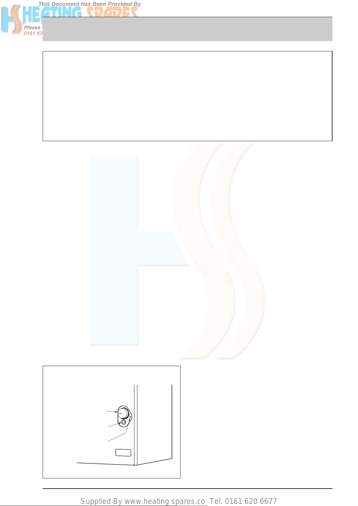
OPERATING INSTRUCTIONS FOR THE USER
APPLIANCE CONTROLS
TEMPERATURE CONTROL
IGNITION AND
LOCK-OUT BUTTON
OVERHEAT WARNING LAMP
Page 3
Supplied By www.heating spares.co Tel. 0161 620 6677
– Turn on the gas supply.
– Turn the boiler control on, and to maximum. Check the
boiler lights.
– Set the boiler control to the required temperature for the
maximum boiler flow. Turning clockwise increases the set
point temperature.
– Make sure the external controls are fully operational and
the complete system is controlled correctly.
1.3.2 To turn the appliance off
The appliance may need to be switched of f for short periods.
If required the boiler control may be rotated to the ‘OFF’ position (completely anti clock wise) which will prevent the appliance from operating in the event of a demand from any external controls.
If the appliance is to be switched off for long periods the boiler control should be rotated to ‘OFF’ and the electrical supply
to the complete system should be isolated.
If the appliance is to be switched off for a prolonged length of
time during severe cold conditions then it is recommended
that the complete heating system and appliance is drained to
prevent freezing. A service engineer would normally be
required for this.
If a frost thermostat is fitted to the heating system, no draining
of the system is required, leave the appliance switched on and the
temperature control at its minimum setting and turn any external
timer controls off. This will allow the appliance to operate via the
frost thermostat and prevent the system from freezing.
1.4 MINIMUM CLEARANCES
The following MINIMUM CLEARANCES must be available for
servicing the appliance:
1.5 ROUTINE SERVICING
To ensure continued efficient operation of the appliance, it is
recommended that it is checked and serviced as necessary
at regular intervals.
The frequency of servicing will depend upon the particular
installation conditions and usage but in general once a year
should be adequate. It is the law that any service work must
be carried out by a registerd person (C.O.R.G.I.).
1.6 GENERAL INFORMATION
1.6.1 Appliance overheat thermostat
The appliance is fitted with a safety cutout thermostat. In the
event of the appliance overheating this will prevent the appliance from functioning.
If this occurs, both the overheat warning lamp and the ignition
lock out indicator will illuminate. Allow the appliance to cool,
depress the ignition-reset button and turn the rotary control
to ‘OFF’. Switch the electricity supply to the appliance off, this
will reset the overheat warning lamp. Switch the electricity
supply to the appliance on and reset the rotary control to its
original position. If the external controls are calling for heat,
the appliance will perform an ignition sequence and the burner will light.
If the situation is repeated, turn off the electrical supply and
consult your installer or a service engineer.
1.6.2 Electrical supply
An interruption in the electrical supply whilst the burner is
alight may cause the overheat thermostat to operate. If this
happens and the electrical supply is restored whilst in this
condition, the warning lamps may illuminate after an ignition
sequence (refer to section 1.6.1). However should the electrical supply be restored after the appliance has cooled, normal
operation will be restored.
1.6.3 Cleaning
Use only a damp cloth and mild detergent to clean the appliance outer casing. Do not use abrasive cleaners. It is recommended to clean the outer case when the appliance is cold.
1.7 SAFETY
It is essential that the instructions in this book are strictly followed for the safe and economical operation of this appliance.
The appliance functions as a fan assisted balanced flue unit.
The flue terminal MUST NOT BE OBSTRUCTED under any circumstances. If damaged, turn off the appliance and consult
the installer, service engineer or gas supplier. If it is known or
suspected that a fault exists on the appliance it MUST NOT be
used until a competent person has rectified the fault.
WARNING: IF A GAS LEAK IS SUSPECTED OR EXISTS,
TURN OFF THE GAS SUPPLY TO THE APPLIANCE AT THE
GAS SERVICE COCK. DO NOT OPERATE ANY ELECTRICAL
SWITCHES. DO NOT OPERATE ANY ELECTRICAL APPLIANCES. OPEN ALL WINDOWS AND DOORS. DO NOT
SMOKE. EXTINGUISH ALL NAKED FLAMES. CONTACT THE
GAS SUPPLIER IMMEDIATELY.
ABOVE THE APPLIANCE CASING 200 mm 8 in
AT THE R.H.S. 15 m m
5
/8in
AT THE L.H.S. 15 m m
5
/8in
BELOW THE APPLIANCE CASING 200 mm 7 7/8in
IN FRONT OF THE APPLIANCE 500 mm 19 3/4in
All descriptions and illustrations provided in this manual have been carefully prepared but we reserve the right to make changes
and improvements in our products that may affect the accuracy of the information contained in this manual.
Page 4
Supplied By www.heating spares.co Tel. 0161 620 6677
Cod. 6274224A - Documentation Dpt.
Sime Ltd
Unit D2 Enterprise Way, Bradford Road, Bradford, West Yorkshire, BD10 8EW
Tel. 0870 9911114 - Fax 0870 9911115
www.sime.ltd.uk - e-mail: [email protected]
 Loading...