

Page 1

SOLIDA 8 PL - ENGLISH
INDEX
1 OPERATION WITH WOOD AND CARBON
1.1 DESCRIPTION . . . . . . . . . . . . . . . . . . . . . . . . . . . . . . . . . . . . . . . . . . . . . . . . . . . . . . . . . . . . . . . . . . . . . . . . . . . . . . . . . . . . . . . . 48
1.2 INSTALLATION . . . . . . . . . . . . . . . . . . . . . . . . . . . . . . . . . . . . . . . . . . . . . . . . . . . . . . . . . . . . . . . . . . . . . . . . . . . . . . . . . . . . . . . 49
1.3 USE AND MAINTENANCE . . . . . . . . . . . . . . . . . . . . . . . . . . . . . . . . . . . . . . . . . . . . . . . . . . . . . . . . . . . . . . . . . . . . . . . . . . . . . . 52
2 OPERATION WITH PELLETS AND SPECIAL KIT
2.1 DESCRIPTION . . . . . . . . . . . . . . . . . . . . . . . . . . . . . . . . . . . . . . . . . . . . . . . . . . . . . . . . . . . . . . . . . . . . . . . . . . . . . . . . . . . . . . . . 53
2.2 INSTALLATION . . . . . . . . . . . . . . . . . . . . . . . . . . . . . . . . . . . . . . . . . . . . . . . . . . . . . . . . . . . . . . . . . . . . . . . . . . . . . . . . . . . . . . . . 54
2.3 USE AND MAINTENANCE . . . . . . . . . . . . . . . . . . . . . . . . . . . . . . . . . . . . . . . . . . . . . . . . . . . . . . . . . . . . . . . . . . . . . . . . . . . . . . 60
Page 2
48
IT
ES
GB
RUS
FR
BE
1 OPERATION WOOD AND CARBON
1.1 DESCRIPTION
1.1.1 INTRUDUCTION
The cast iron “SOLIDA 8 PL” boilers are a
valid solution for the present energetic problems, since they can run with solid fuels:
wood and carbon.
“SOLIDA 8 PL” boilers conform to Directive
PED 97/23/CEE.
1.1.2 SUPPLY
The boilers are supplied in three separate parcels:
– Boiler body assembled and equipped with
loading port, ash boxes port, smoke chamber with blast gate damper, ash collection
basin and thermostatic draught regulator.
Bag containing: 2 handles for the ports, a
screw with bakelite knob for the manual
adjustment of the blast gate damper, a
contact spring for the bulb of the thermometer and the M6 lever to be fixed at the
blast gate damper. “Test certificate” to be
kept with the documents of the boiler.
Miscellaneous accessories required to use
the boiler with pellets (see Section 2 in the
manual).
– Cardboard box for casing with thermo-
meter and documents bag.
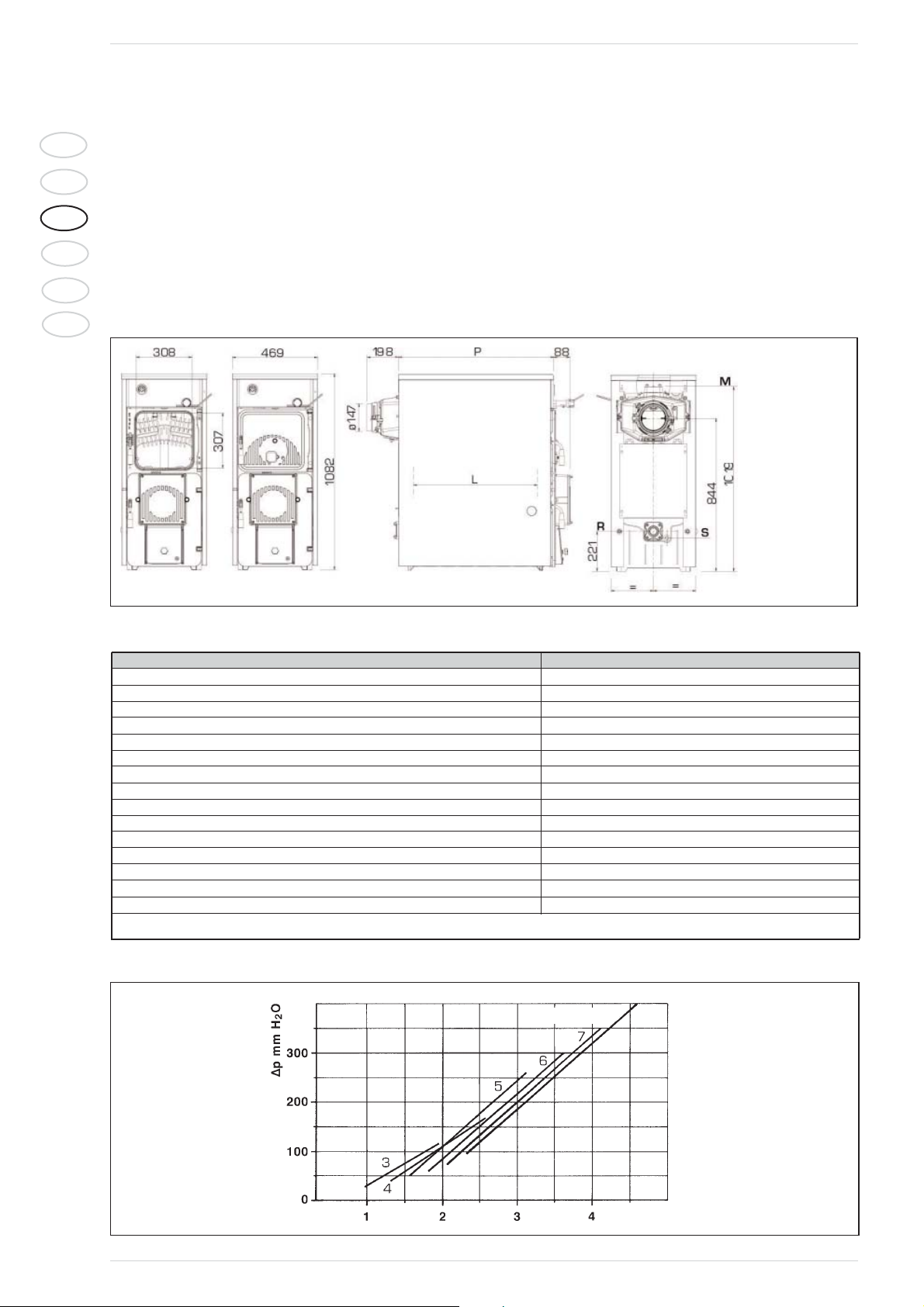
1.1.3 DIMENSIONS
Fig. 1
FIXTURES
M C.H. flow 2”
(UNI-ISO 7/1)
R C.H. return 2”
(UNI-ISO 7/1)
S Boiler drain 1/2”
(UNI-ISO 7/1)
Fig. 2
1.1.5 HEAD LOSSES
1.1.4 TECHNICAL FEATURES
Model SOLIDA 8 PL
Carbon heat rate*
kW (kcal/h) 39,5 (34.000)
Performance class
2
Duration of a coal load
h * 4
Duration of a wood load
h * 2
Load volume
dm
3
59,5
Minimum chimney depression
mbar 0,18
P (depth)
mm 855
L (combustion chamber depth)
mm 690
Number of elements
n° 8
Max. operating temperature
°C 95
Min. temperature of water returned to the plant
°C 50
Max working pressure
bar 4
Test pressure
bar 6
Boiler capacity
l43
Weight
kg 350
* The heat rate will be reduced with about 10% for the operation with hard wood (birch – oak – olive).
Flow rate m3/h
SOLIDA 8 PL
Page 3
49
IT
ES
GB
RUS
FR
BE
1.2 INSTALLATION
1.2.1 BOILER ROOM
Check that the room has the requirements
and features in accordance to the rules in
force. Furthermore, the room should be
aired, in order to have a regular combustion.
Therefore it is necessary to practice some
openings in the walls of the room, which correspond to the following requirements:
– They should have a free section of at
least 6 cm
2
for each 1,163 kW (1000
kcal/h). The minimum opening section
shouldn’t be smaller than 100 cm2. The
section can also be calculated, using the
following ratio:
where “S” is expressed in cm2.
“Q” is expressed in kcal/h
– The opening should be situated on the
lower part of an outer wall, preferably on
the opposite of the one for the combustion gas discharge.
1.2.2 CONNECTION TO THE FLUE
A flue should correspond to the following
requirements:
– It should be of waterproof material and
resistant to temperature of smokes and
related condensations.
–
It should be of a sufficient mechanical resistance and a weak thermal conductivity.
– It should be perfectly hermetic in order
to avoid cooling of the flue.
– It should have the most possible vertical
process and the terminal part should
have a static aspirator, which assures an
efficient and constant discharge of the
combustion product.
– In order to avoid the wind creating a very
high pressure around the chimneypot,
so that it prevails on the ascensional
force of the combustion gas, it is necessary that the discharge orifice hangs
over at least 0,4 meters of whatever
structure adjacent the chimney itself
(including the roof ridge) of at least 8
meters.
–
The flue shouldn’t have a diameter inferior to the boiler connection; for flues with
square or rectangular sections, the internal section should be higher than 10%
compared to the boiler connection one.
– The net section of the flue can be obtai-
ned from the following ratio:
S section resulting in cm
2
K reduction coefficient:
– 0,045 for wood
– 0,030 for carbon
P boiler capacity in kcal/h
H height of the chimney in meters
measured from the flame axis at the
exhaust of the chimney in the atmosphere. For the dimensioning of the
flue you should consider the effective height of the chimney in meters,
measured from the flame axis at the
top, diminished with:
– 0,50 m for each direction chan-
ging of the connection tube
between boiler and flue;
– 1,00 m for each horizontal deve-
lopment meter of the connection
itself.
1.2.3 CONNECTION OF THE PLANT
The connections should be easily disconnected by means of pipelines with revolving
joints. It is always advisable to assemble suitable interception shutters on the piping of
the heating installation.
CAUTION: It is obligatory to assemble
safety valves on the system.
Plant filling
Before star ting with the connection of the
boiler it is advisable to let the water circulate in the piping, in order to eliminate possible foreign bodies, which could compromise
the correct operation of the appliance.
The filling should be carried out slowly in
order to make the air bubbles go out through the proper outlets, placed on the heating
installation.
The cold loading pressure of the plant and
the pre-blowing pressure of the expansion
tank, should correspond or however
shouldn’t be inferior to the height of the static column of the plant in case of closed cir-
cuit heating installations (for example, for a
static column of 5 meters, the pre-loading
pressure of the tank and the loading pressure of the plant should correspond at least
to a minimum value of 0,5 bar).
Features of the feed water
THE TREATMENT OF THE WATER USED
FOR THE HEATING INSTALLATION IS ABSOLUTELY NECESSARY IN THE FOLLOWING
CASES:
– Very vast plants (with high water con-
tents).
– Frequent replenishment water inlets in
the plant.
– If the partial or total emptying of the
plant should be necessary.
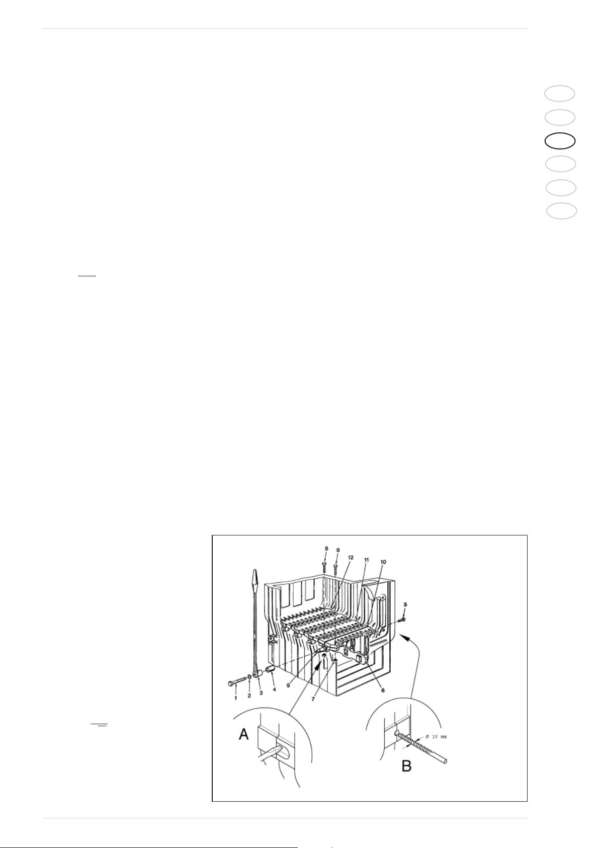
1.2.4 BRAZIER GRID ASSEMBLY
(optional)
In order to carry out the assembly proceed
in the following way (fig. 3):
– Punch the card of the outer part,
between the front head and the intermediate element, using a bit of 10 ø as indicated in the detail (B).
– Place the back grid (12) in the combu-
stion chamber.
– Place the front grid (10) and block it to
the hub (9) with the screws (8) and the
nuts (7); block the front grid from the
right side of the boiler body with the
screws (5).
– Hook the tie rod (6) to the seats extrac-
ted from the front and rear grid.
– Place the intermediate grids (11).
– Introduce the ring (4) and the lever (3) on
the hub (9), fixing then everything with
the washer (2) and the screw (1).
Q
S=
10 0
P
S=K
3H
LEGEND
1 Screw TE M8 x 10
2 Grower washer
3 Grid lever
4 Ring for lever
5 Screw TE M8 x 35
6 Tie rod
7 Nut M 10
8 Screw TE M10 x 50
9 Hub
10 Front grid
11 Intermediate grid
12 Rear grid
Fig. 3
Page 4
50
IT
ES
GB
RUS
FR
BE
1.2.5
ASSEMBLY OF THE
ACCESSORIES
The closing handles for the ports and the
screw with the adjustment knob for the
blast gate damper are supplied separately,
since they could be damaged during the
transport.
Both the handles and the screws with knob
are packed in a nylon bag, introduced inside
the ash collection basin.
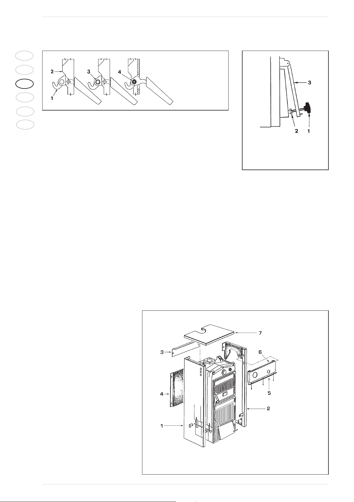
For the assembly of the handles proceed as
following (fig. 4):
–
Take a handle (1), insert it in the opening
of the load port (2) and introduce the roll
(3) in the opening of the handle; block the
handle introducing the elastic split pin (4).
– Carry out the same operation for the
handle of the ash box port.
To assemble the screw with the knob, proceed as follows (fig. 5):
– Remove the screw M8 x 60, which fixes
the air blast damper to the ash box port
and screw the screw with the bakelite
knob (1) on, which is supplied in the
packaging.
Place the blind nut with cap (2) at the
end of screw M 10.
– Fix lever M6 to the air blast damper (3)
placing it in a horizontal direction on the
right. The lever has an opening at its end,
where the chainlet of the thermostatic
regulator will be connected.
1.2.6 CASING ASSEMBLY
Two superior tie rods are screwed on three
nuts at the front side of the boiler: the
second and the third nut serve to place correctly the lateral sides of the casing.
Two nuts one to fix the clamp holders for
the lateral sides are screwed on the inferior
tie rods, both from the front side and from
the rear side of the boiler. The assembly of
the casing components has to be carried
out in the following way (fig. 6):
– Unscrew with some rotations the
second or third nut of each tie rod.
– Hook the left side (1) on the lower tie rod
and superior of the boiler and adjust the
position of the nut and locknut of the
upper tie rod.
–
Fix the lateral side in blocking the locknut.
– In order to assembly the right side (2)
proceed in the same way.
– Hook the front upper board (3) introdu-
cing the two splines in the opening, obtai-
ned on each side.
– Carry out the same operation to fix the
back lower board (4).
– The protection deflector (5) is fixed to the
control board (6) with three self-threading screws.
Fix the board by means of the pressure
stakes.
Then unwind the capillary of the thermometer and introduce it in the lef t sheath
of the posterior head, introducing the
contact spring.
The right sheath can be needed for the
check thermometer.
– Fix the cover (7) at the lateral sides of
the boiler.
NOTE: Keep the “Test certification”
together with the boiler documents in the
combustion chamber.
1.2.7 DRAUGHT REGULATOR
The boilers “SOLIDA 8 PL” can assemble indif-
ferently 2 types of thermostatic regulators.
NOTE:
In order to fix the lever with the
chainlet in the regulator holder it is necessary to remove the deflector in aluminum,
which is assembled on the control board, by
unscrewing the three screws that fix it (fig.
6).
Replace the protection deflector after
the assembling and related adjustment.
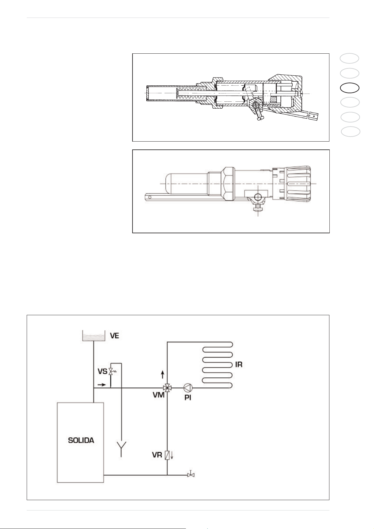
“THERMOMAT RT-C” Regulator
The “Thermomat” regulator is equipped
with a thermosetting resin knob of an adjustment field from 30 to 100 °C (fig. 7).
Screw the regulator on the 3/4” opening of
the anterior head and orientate the red
index on the upper part.
The lever with the chainlet should be introduced in the regulator holder after having
assembled the instrument holder board
and after having removed the plastic lock.
If the joint is taken out, which fixes the lever
with the chainlet, take care in assembling it
LEGEND
1 Handle
2 Load port
3 Roll
4 Elastic split pin
Fig. 4
LEGEND
1 Screw with knob M10 x 70
2 Blind nut with cap
3 Blast gate damper
Fig. 5
LEGEND
1 Left side
2 Right side
3 Posterior superior board
4 Posterior inferior board
5 Protection deflector
6 Control board
7 Cover
Fig. 6
Page 5
51
IT
ES
GB
RUS
FR
BE
again in the same position. After having placed the knob at 60°C, block the lever with
the chainlet in a slightly inclined position
downwards, so that the chainlet will be in
axis with the air gate damper.
For the adjustment of the “Thermomat”,
which essentially consists in the determination of the chainlet length, proceed in the following way:
– Place the knob at 60°C.
– Switch on the boiler with opened air gate
damper.
– When the water temperature of 60° C
is reached in the boiler, fix the chainlet in
such a way on the lever of the air gate
damper, in order to obtain an opening of
about 1 mm.
– Now the regulator is calibrated and it is
possible to choose the desired operating
temperature by rotating the knob.
“REGULUS RT2” Regulator
The adjustment field is included between 30
and 90°C (fig. 8).
Follow the same instructions of the
“Thermomat” regulator for the assembly
and the activation.
Fig. 8
1.2.8 HYDRAULIC CONNECTION DIAGRAM
Open expansion tank system
Fig. 9
“REGULUS RT2” Regulator
Fig. 7
“THERMOMAT RT-C” Regulator
LEGEND
VE Open expansion tank
VS System safety valve 3 BAR - 1/2”
VM Mixing valve
VR Check valve
PI System pump
IR Heating system
Page 6
52
IT
ES
GB
RUS
FR
BE
1.3 USE AND MAINTENANCE
1.3.1 PRELIMINARY
IGNITION CHECKS
Before the use of the boiler, it is necessary
to follow the following instructions:
– The installation where the boiler is con-
nected to, should be preferably with an
open expansion tank (fig. 10).
– The tube, which connects the boiler to
the expansion tank, should have an adequate diameter according to the norms
in force.
– The heating pump should always be run-
ning during the operation of the boiler.
– A possible ambient thermostat should
never interrupt the pump operation.
– If the installation is equipped with a 3 or
4 ways mixing valve, it should always be
placed in the opening position toward
the installation.
– Be assure that the draught regulator
works regularly and that there aren’t
impediments, which block the automatic
operation of the air gate damper.
1.3.2 CLEANING
The cleaning should be carried out with a
certain frequency providing besides the
cleaning of the smoke passages, also the
cleaning of the ash box, removing the ashes,
which are contained in the collection basin.
Use a proper pull-through for the cleaning
of the smoke passages (fig. 11).
1.3.3 MAINTENANCE
Do not perform any maintenance work,
dismantling or removal of parts without
properly emptying the boiler first.
The boiler must not be emptied when the
water is hot.
CAUTION:
The safety valve on the system must be
inspected by technically qualified personnel every five years.
If the system is completely emptied and
remains unused for some time, the safety
valve must be inspected before it is used
again. If the safety valve should malfunction and cannot be re-calibrated, replace
it with a new 1/2” valve calibrated to 3
BAR and conforming with Directive PED
97/23/CEE.
Fig. 10
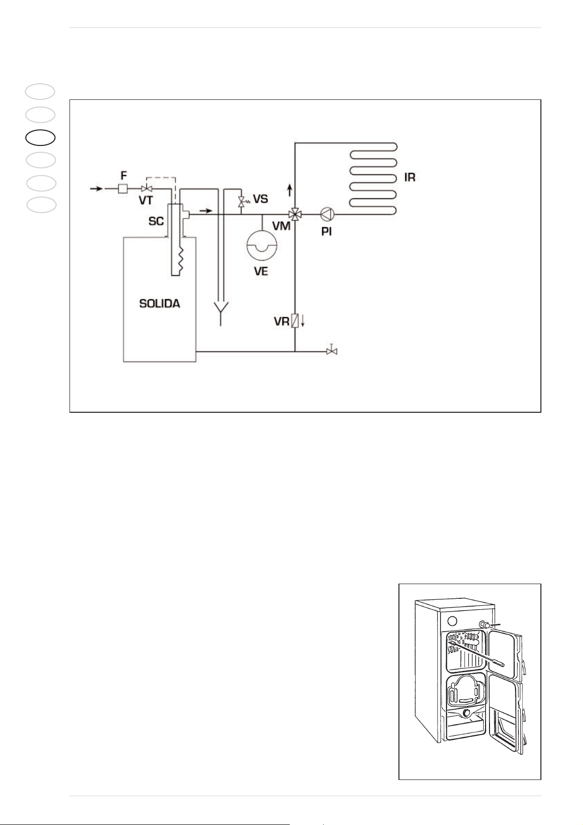
Closed expansion tank system with heat exchanger and optional thermostat valve
Fig. 9/a
LEGEND
VE Expansion tank
VS System safety valve 3 BAR - 1/2”
VM Mixing valve
VR Check valve
PI System pump
IR Heating system
VT Thermostat valve
SC Safety exchanger
F Filter
CAUTION: The safety exchanger is supplied in an
optional kit code 8105200.
Temperature of the water supplied to the safety
heat exchanger: 10°C.
Pressure of the water supplied to the safety heat
exchanger: 2 bar.
Page 7
53
IT
ES
GB
RUS
FR
BE
2.1 DESCRIPTION
2.1.1 INTRODUCTION
SOLIDA 8 PL boilers can be converted in
order to be used with pellets.
In this case it is however necessary to separately order the special Pellet kit 200
(Code 8075910), 300 (Code 8075911) or
500 (Code 8075912), which includes:
- Two-stage burner.
- Pellet feeder with motor and volute.
- Painted pellet container (with capacities
ranging from 200 to 500 dm
3
).
- Electronic control panel for the automatic burner adjustment.
The burner complies with Class 3 in accordance with EN 303-5.
To obtain an efficient performances, it is
advisable to use pellets that have been
certified by an authorized body (the characteristics of the pellets used by boiler
SOLIDA 8 PL are specified in standard
DIN plus).
2 OPERATION WITH PELLETS AND SPECIAL KIT
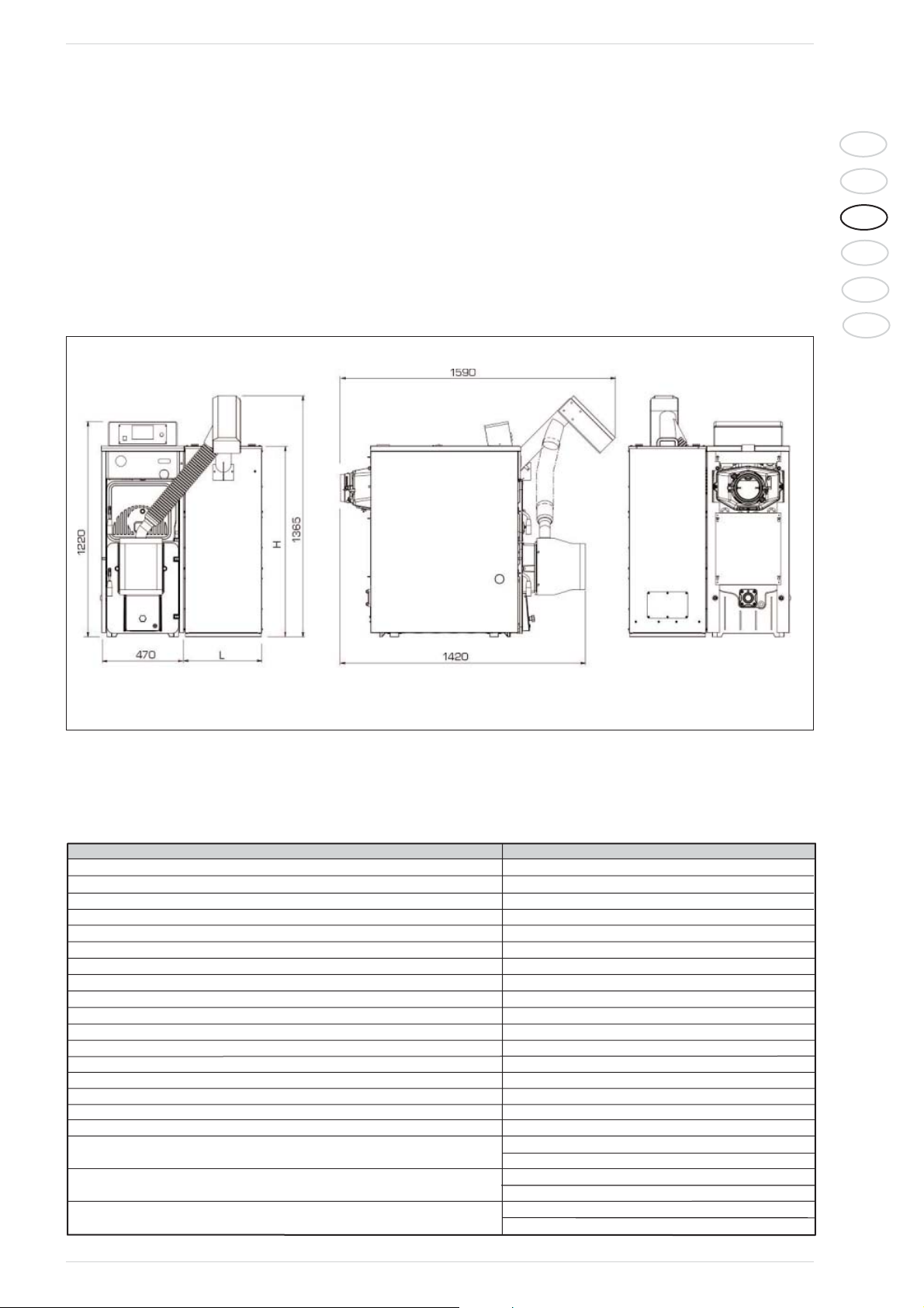
2.1.2 DIMENSIONS
Fig. 12
2.1.3 TECHNICAL FEATURES
Model S
OLIDA 8 PL
Heat output nominal kW 26,28
Heat output minimum kW 7,88
Heat input nominal kW 30,54
Heat input minimum kW 9,96
Efficiency maximum % 86,0
Efficiency minimum % 79,1
Classification of the boiler
Class 3
CO mg/m3to 10% of O2 to heat output nominal 154,0
CO mg/m3to 10% of O2 to heat output minumum 2114,6
OGC mg/m3to 10% of O2 to heat output nominal 1,7
OGC mg/m3to 10% of O2 to heat output minumum 25,9
G mg/m3to 10% of O2 to heat output nominal 15 ,11
G mg/m3to 10% of O2 to heat output minumum ----
Dimensions of the 200 dm3pallet container H1081
L440
Dimensions of the 300 dm
3
pallet container H1381
L440
Dimensions of the 500 dm3pallet container H1481
L640
Page 8
54
IT
ES
GB
RUS
FR
BE
2.2 INSTALLATION
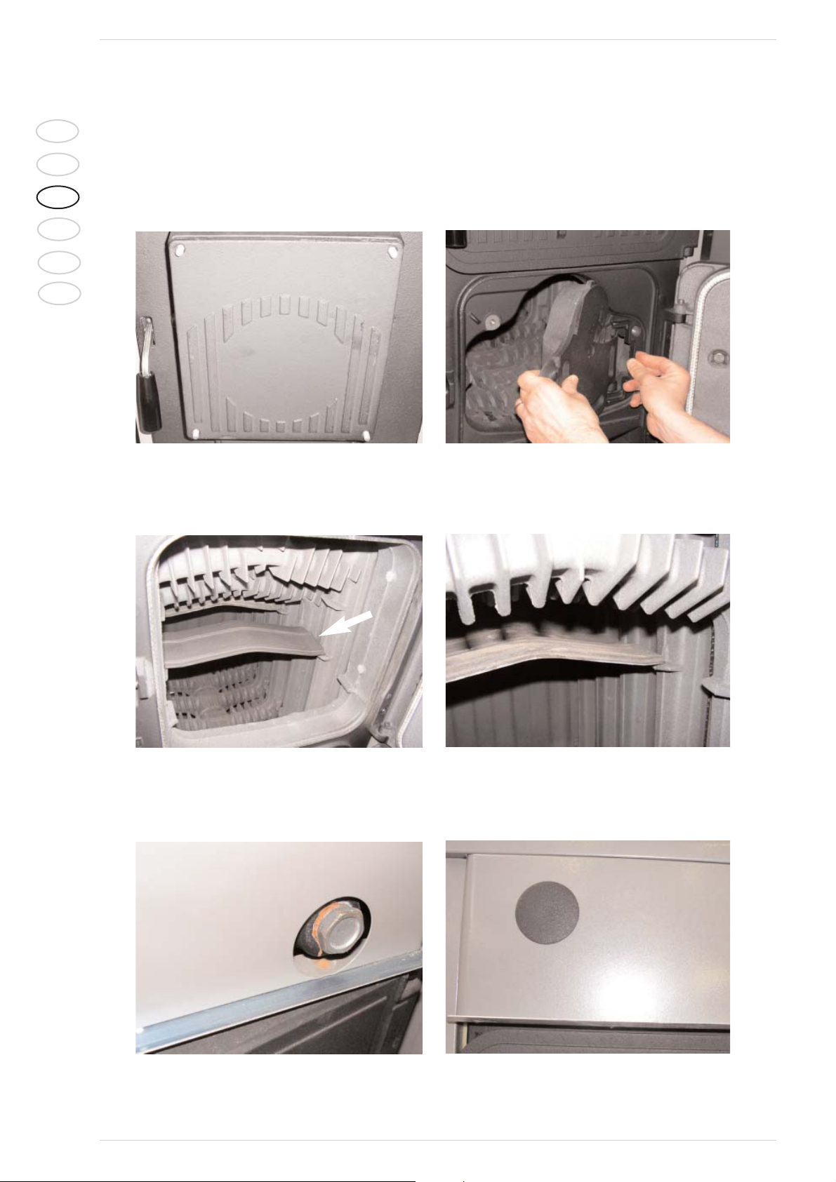
2.2.1 CONFIGURATION OF THE BOILER FOR THE USE WITH PELLETS AND OPTIONAL KIT
A) Remove the blind flange in cast iron and disassemble the grille, hinge and hake along with the setting screws.
B) Assemble the four baffles supplied, pushing the first deflector against the rear head of the boiler and then the others.
C) Disassemble the boiler thermostatic valve, if present, and close the hole with the cap supplied. Disassemble also the boiler thermometer, if fit-
ted, and close the hole on the front piece with the plastic cap supplied.
Fig. 13: Disassembly of blind flange
Fig. 13.1: Disassembly of grille
Fig. 13.2: Assembly of baffle
Fig. 13.3: Assembly of baffle
Fig. 13.4: Assembly of cap
Fig. 13.5: Closing the front piece
Page 9
55
IT
ES
GB
RUS
FR
BE
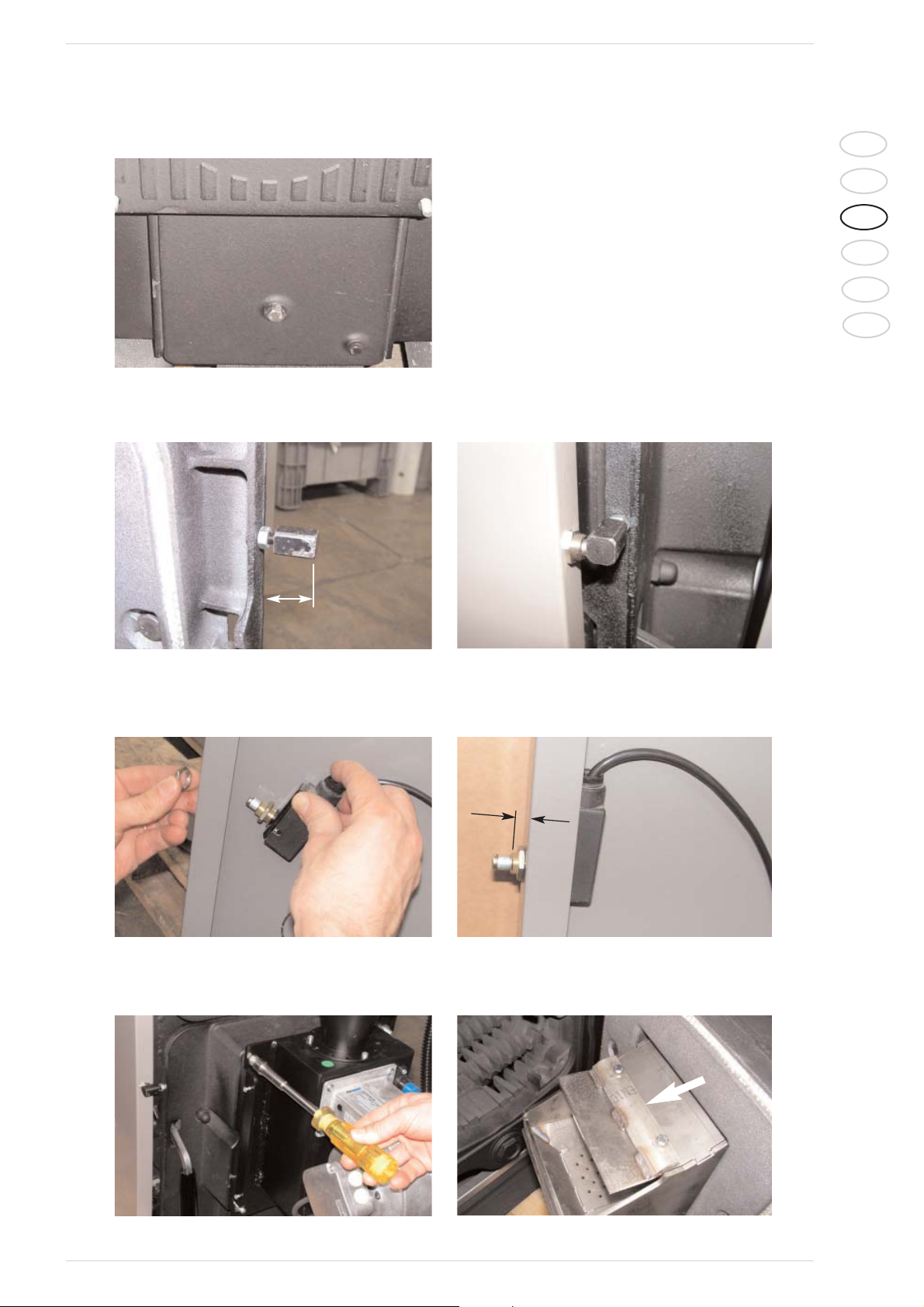
D) Block the inlet port if the boiler has already been used with wood or coal.
E) Insert the micro pressing pin into the hole on the combustion chamber door and adjust its projection with nut M6.
F) Insert the hard-wired safety microswitch into the hole on the left side of the mantle. Adjust the projection using the hex jam nuts. Check the
operation after assembly.
G) Assemble the two-stage burner fixing it onto the flange by means of the previously disassembled nuts in order to remove the blind flange in
cast iron. Assemble the flame baf fle.
Fig. 13.6: Inlet port
Fig. 13.7: Assembly of micro pressing pin
Fig. 13.8: Pin closing position
Fig. 13.9: Assembly of microswitch
Fig. 13.10: Microswitch position
Fig. 13.11: Assembly of burner
Fig. 13.12: Assembly of flame baffle
27/28 mm
7 mm
Page 10
56
IT
ES
GB
RUS
FR
BE
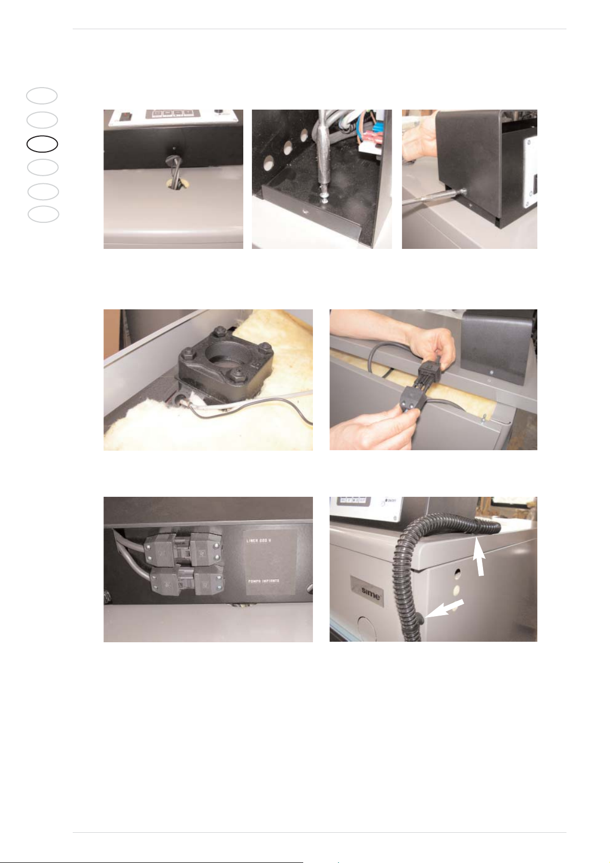
H) Assemble the control panel after inserting the probes and the microswitch cable into the hole on the mantle cover. Remove the control panel
cover and reassemble the cover after fixing the panel to the cover.
I) Apply the fiber glass insulation, supplied to protect the cables, on the boiler body. Then, insert the probes into the sleeve on the rear head and
connect the micro-switch cable. To protect the micro-switch cable, always verify that is it positioned inside the bend on the side of the mantle.
Close the mantle cover.
L) Connect the power supply line and plant pump before assembling the cable straps.
Fig. 13.16: Insertion of the probes into the sheath
Fig. 13.17: Microswitch wiring
Fig. 13.13: Hole on cover
Fig. 13.15: Control panel cover
Fig. 13.14: Fixing of control panel
Fig. 13.18: Power supply
Fig. 13.19: Cable straps
Page 11
57
IT
ES
GB
RUS
FR
BE
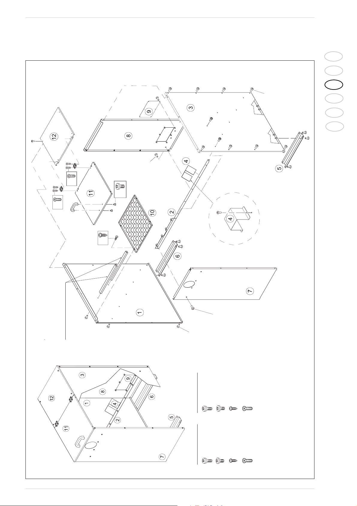
M) Assemble the pellet container (with a capacity of 200 - 500 dm3) on the right of the boiler, in support to the boiler and align its front section.
Fig. 13.20: Assembly of the elements of the pellet container
Tie rods
Only for 500 dm
3
containers
4 x
4 x
4 x
4 x
2 x
6 x
)
3
)
3
6 x (500 dm
4 x (200-300 dm
2 x
5 x
2 x
)
3
)
3
10 x (500 dm
8 x (200-300 dm
4 x
3
2 x
Tiranti solo
per contenitore
da 500 dm
5 x
4 x
3
)
3
)
3
10 x (500 dm
8 x (200-300 dm
3
TCB M5x12 (66 x)
Mod. 500 dm
3
TCB M5x12 (54 x)
Mod. 200-300 dm
)
)
3
6 x (500 dm
4 x (200-300 dm
TCB 7SPx3/8” (4 x)
TCB M6x8 (2 x)
TCB 7SPx3/8” (4 x)
TCB M6x8 (2 x)
TSP M5x20 (8 x)
TSP M5x20 (8 x)
Page 12
58
IT
ES
GB
RUS
FR
BE
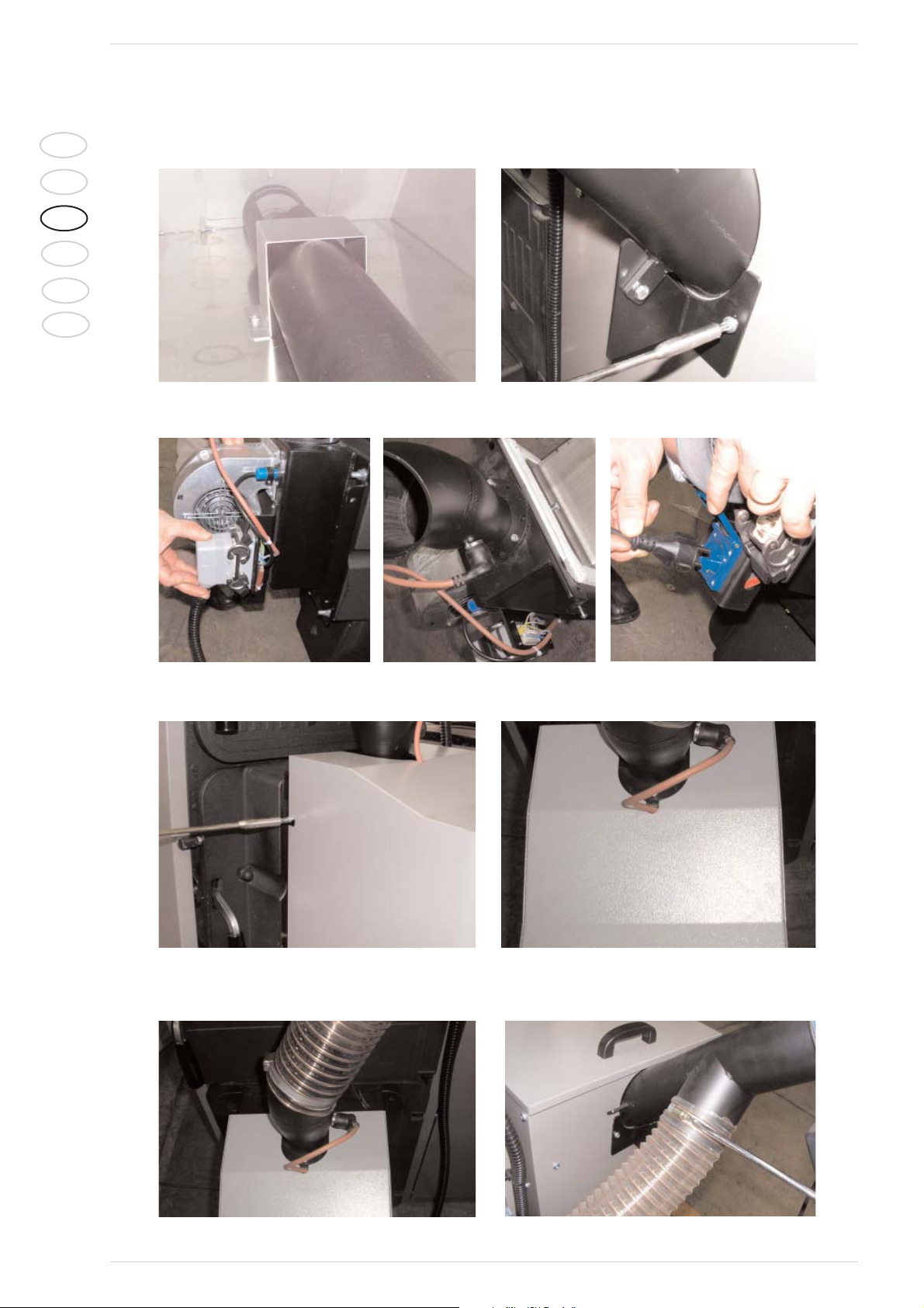
N) Push the feeder volute with the motor into its slot inside the pellet container (with a 200 -500 dm3capacity) until its stops, and verify that the
bucket is pointing upwards. Fix the volute onto the container using the screws that are already available on the container.
O) Connect the 10 pole connector (JB) on the control panel to the burner, safety sensor and to the volute motor power plug.
P) Assemble the burner motor verifying that it is correctly connected to the safety sensor.
M) Connect the flexible self-extinguishing pipe with the straps to the burner and pellet feeding volute. Verify that the tube is fully stretched to pre-
vent it from blocking the pellets.
Fig. 13.21: Insertion of the volute into the pellet container
Fig. 13.22: Volute fixing
Fig. 13.23: Assembly of connector JB
Fig. 13.25: Volute motor plug
Fig. 13.24: Connection of sensor
Fig. 13.26: Assembly of burner cover
Fig. 13.27: Checking the sensor connection
Fig. 13.28: Fixing the lower section of the flexible tube
Fig. 13.29: Fixing the upper section of the flexible tube
Page 13
59
IT
ES
GB
RUS
FR
BE
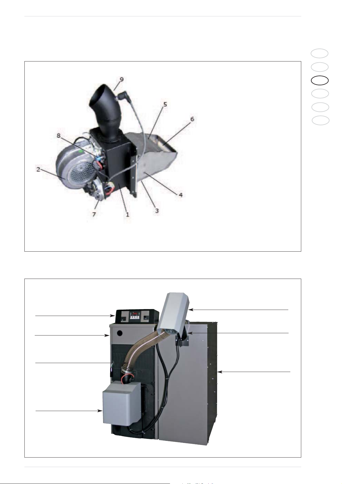
2.2.2 BURNER’S DESCRIPTION
LEGEND
1 Borner’s body
(air ducts and pellets loading)
2Fan
3 Fire place body
4 Electric coil support
5 Grate with electric coil
6 Fire grate (removable for cleaning)
7 Male plug (interface from display to
burner’s devices)
8 Fotoresistance
9 Pellet’s estrance (safety sensor on the
pellet’s inlet tube)
Fig. 14
2.2.3 BOILER AND PELLET CONTAINER ASSEMBLY
Fig. 15
Pellet container with a
200 - 500 dm3capacity
Feeder with volute motor
Control panel
Self-extinguishing pipe
Burner
Boiler SOLIDA 8 PL
Screw
Page 14
60
IT
ES
GB
RUS
FR
BE
2.3 USE AND MAINTENANCE
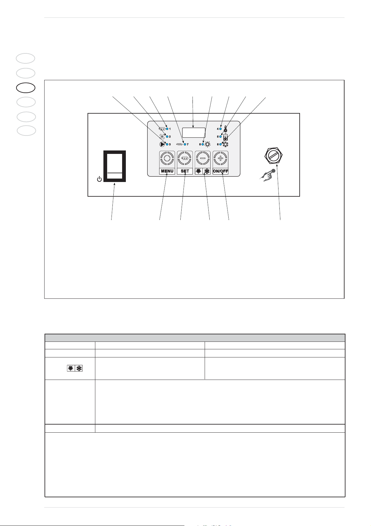
2.3.1 CONTROL PANEL
123456789
101112131415
LEGEND
1 Led screw ON
2 Fan led
3 Pump led
4 Boiler led
5 Flame led
6 Pump active/winter
7 Electric coil led
8 Pump not active/summer
9 Display
10 Manual rearmament thermostat
11 ON/OFF key
12 Winter/summer key
13 Screw/set key
14 Menu key
15 Main switch
Fig. 16
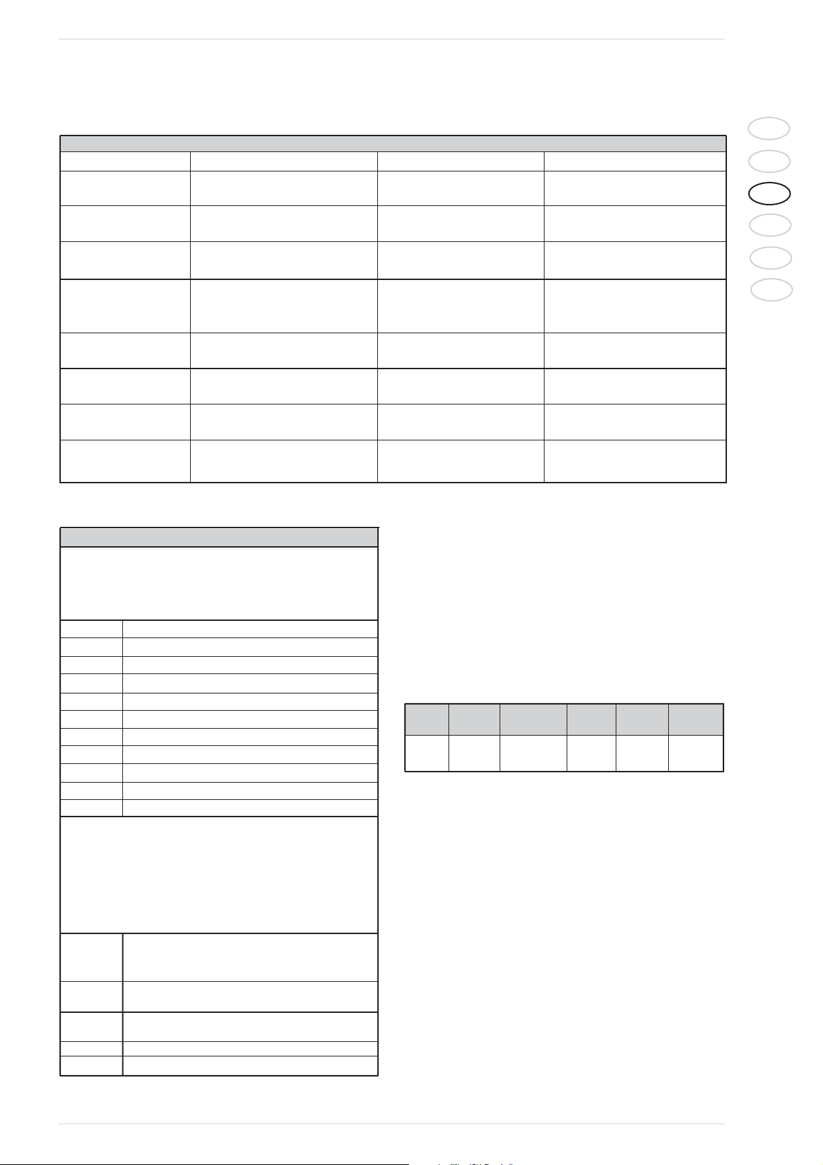
Buttons
Button 5 sec pressed button One click function
(+) ON/OFF System ON/System OFF
Into the menu it allows to increase the parameters value
By pressing it only once it will
(--) switch from summer to winter Onto the menu it allows to decrease the parameters value
operation and to the contrary
By pressing the key it’s possible to manually load the feeding screw.
This operation is allowed only when boiler’s off.
SET When manual loading is active the display shows “Load”.
By releasing the key the loading stops. The load has happened when the material begins to come down
from the self-extinguishing pipe, to this point to leave endured the push-button.
Into the Menu it shows code/value parameters.
MENU This key allows to regulate boiler’s thermostat
NOTE:
• When the unit is off, by pressing the key ON/+ o quello OFF/– when an alert is shown it’s possible to reset alert. If the alert still is
active, the display shows it again.
• During the setting of the system it’s, the display may shows the current flame luminosity.
– By pressing in the same time keys + and – 5 sec, the display will shows the flame luminosity.
– The data will be shown for 5 sec and the display shows the current data again.
2.3.2 BUTTONS CONTROL PANEL
Page 15
61
IT
ES
GB
RUS
FR
BE
2.3.4 DISPLAY CONTROL PANEL 2.3.5 MENU
The parameters of the regulator are programmable by using the
menu.
Two menu levels are at disposal: user menu and protected menu.
User menu:
Accessible by pressing menu key on the control panel. It allows to see
the set temperature in the boiler, which’s value can be changed from
a min of 60°C and a max of 85°C, by pressing the keys + and –.
- The data will be automatically recorded after 20 sec. without to
touch any key or by pressing again the key MENU.
2.3.6 OPERATION
Introduction
The control panel regulates the working of the unit SOLIDA 8 PL,
allowing automatic ignition and feeding of the fuel by the screw motor,
drawing pellet directely from the container. A photoresistance controls the flame and a sensor controls the water temperature in the
boiler. The setting of all the parameters determinates the operation
of the system.
Theese parameters are included in a special menu reserved to qualified personnel.
Operation conditions
Before ignition fill the screw tube with pellet by using the key “set”:
A) Condition off: display OFF.
This condition is reached afther the blowingout phase.
B) Check-up condition: display Chc.
it cleans the combustion chamber before ignition.
LED Sigla Description Default Minimum Maximum
value value value
Boiler TH - Boiler 80 °C 60°C 88°C
CALDAIA thermostat
DISPLAY MESSAGES
Temperatura/State/Allarm
The 3 digit display shows the water temperature in the boiler, the
state of the system and the possible alarms.
OFF Off
Chc Check up
Acc Ignition
Stb Stabilization
nor Normal
rEc Ignition recovering
Mod Modulation
MAn Stand - by
Sic Safety
Spe On put out
ALt Allarm present
In case any error occurs, taking the boiler to the blowing - out, the
display shows an alternance of the messages “Alt” - “Spe” (indica-
ting the boiler’s blow-out), the error cause and the boiler’s tempe-
rature. The shown messages are the following:
Action of the manual
TSi rearmament safety thermostat
on boiler’s temperature
TPE Action of the manual rearmament safety
thermostat. On pellet’s inlet tube
Sic Overheating error readed by
the e-board
Acc Ignition failed
SPA Occasional blowing - out
See Cap 2.3.8 troubleshooting and fixes
2.3.3 LED CONTROL PANEL
LED’s
Description On Flashing Off
LED 1 Feeding screw on - Fellin screw off
Screw
LED 2 Fan on - Fan off
Fan
LED 3 System pump on System pump set off System pump off
Pump by room thermostat
LED 4 Boiler’s temperature lower Burner’s modulating Temperature higher
Boiler than “boiler thermostat - delta than “boiler’s termostat”
modulation”
LED 5 Flame luminosity readed Burner’s on Flame luminosity not readed
Flame blowing - out phase
LED 6 System pump actived - System pump not actived
Winter
LED 7 Ignition coil on - Ignition coil off
Electric coil
LED 8 System pump not actived System pump actived
Summer
Page 16

62
IT
ES
GB
RUS
FR
BE
C) Ignition condition: display Acc.
It is divided in three phases:
1.
Pre-heating of electric coil
: increasing
coil temperature befor pellet’s feeding.
2.
Fixed ignition
: it serves to feed the
usefull quantity of pellet for the ignition.
3.
Variable ignition
: It servs to start and
makes the flame stronger befor the passage to the next phases.
D) Stabilization condition: display Stb.
It servs to adjust the combustion befor
to get into the normal operation.
E) Normal operation: display shows boi-
ler’s temperature.
This phase is active after stb condition.
F) Modulation condition: display Mod.
This phase serv to reduce the power of
the burner before to reach the setboiler’s temperature TH-CALDAIA. Default
of delta-mod is set on 5°C.
G) Mainteinance condition: display MAn.
This phese is active when the boilers
temperature is higher than “th-caldaia”
and it is divided in three phases:
1.
Blowing - out
: it servers to blow out
the flame and to decrease the residual
heat till the flame luminosity is lower
than th-off.
2.
Final - cleaning
: it servers to clean - up
the fire grate.
3.
Maintenance
: waiting phase of the
system.
H) Ignition recovering: display Rec.
This phase is active when ignition is
interrupted.
I) Safety operation: display Sic.
It signals and controls safety conditions
of the system.
L) Blowing - out condition: display SPE.
It enables when you manually switch the
boiler off or if an alarm occurs (automatic shutdown).
Divided in two phases:
1.
Blowing-out
: it servers to blow-out the
flame and to decrease the residual heat
till the flame luminosity is lower than the
set value TH-OFF.
2.
Final cleaning
: it servers to clean-up
the fire grate.
M) Overtemperature alarm: display Alt -
tSi.
This message displays when mechanical
thermostat with manual reset feature,
located inside the control panel control
box, triggers. It electrically interrupts the
power supplied to the burner if the temperature of the water inside the boiler
reaches 95°C.
As soon as the temperature lowers, it is
necessary to reset the thermostat in
order to restart the burner, by loosening
the cap and pressing the button.
N) Overtemperature alarm on pellet inlet
connection: display Alt - tPE.
Even the pellet inlet tube is fitted with a
contact thermostat, which can be
manually reset and that stops the pellet
from being fed when the temperature
inside the tube reaches 90°C.
O) Accidental shutdown alarm: display Alt-
SPA.
This message displays when there is no
fuel in the burner.
Page 17
63
IT
ES
GB
RUS
FR
BE
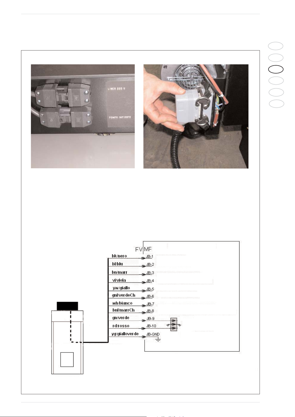
2.3.7 ELECTRICAL CONNECTION DIAGRAM
10 POLES CONNECTOR FROM BOILER’S
ELECTRONIC PANEL TO THE BURNER (JB)
Connecting the power supply
respect polarity (LINEA 220 V)
It’s important to respect the polarity of the
main connection to avoid pellets burners
electronic devices malfunctioning.
Fig. 17
BOILER’S BODY
BURNER’S BODY
ELECTRONIC
BOARD - DISPLAY
(SY325)
PROTECTION CABLE
IGNITION COIL
IGNITION 1000 W
FAN FOR PRIMARY
COMBUSTION AIR
PHOTORESISTANCE
MANUAL RESR. SAFETY THERMOSTAT
ON PELLET INLET TUBE
FEEDING SCREWS PLUG
Page 18

64
IT
ES
GB
RUS
FR
BE
Fig. 18
2.3.8 WIRING DIAGRAM
BOILER THERMOSTAT
(OPTIONAL)
ROOM THERMOSTAT
(OPTIONAL)
MICROSWITCH
DOOR
NTC100K
BOILER
TEMPERATURE
PROBE
SAFETY THERMOSTAT IN
PELLET COMPARTMENT
WITH MANUAL RESET
FEATURE
PHOTO-RESISTANCE
POWER PLUG
MAIN SWITCH
FAN FOR MAIN
COMBUSTIVE
AIR (BURNER)
MAX. THERMOSTAT WITH
MANUAL RESET FEATURE
VOLUTE
IGNITION
PLUG 1000 W
C.H. PUMP
RECIRCULATING/BOILER PUMP
(OPTIONAL)
FUSE 5A
TYPE DELAYED
Page 19
65
IT
ES
GB
RUS
FR
BE
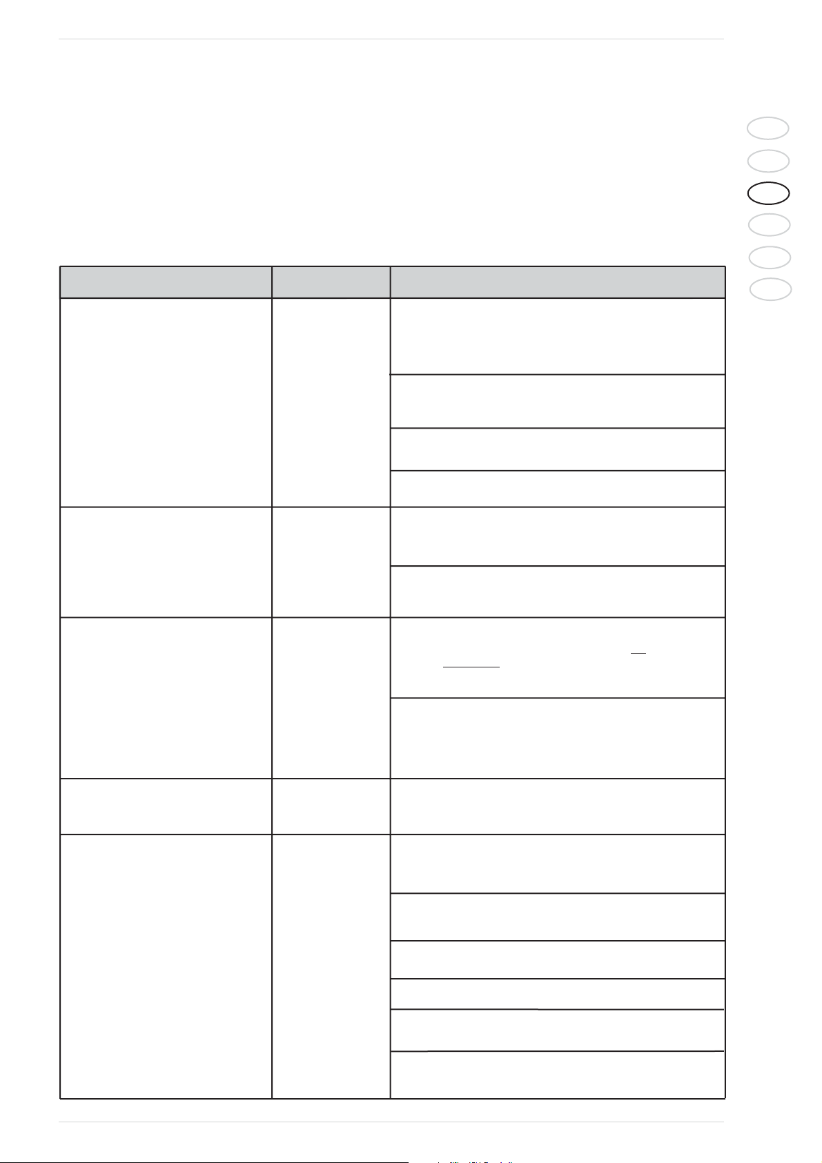
PROBLEM DISPLAY FIX
Alt +
The burner is Alt + The safety thermostat has switched off because
blocked tSic the water boiler temperature has exceeded the
(pos. 10, fig. 15) and press the reset button, with
temperature < 90°C.
Check the working of the system pump, es.
summer function active and boiler temperature
set over 80°C.
System water does’nt circulate well (air inside
the system)
Wrong closing of shutter.
The burner was stopped Alt + Abnormal blow-out: make sure that the pellets
and doesen‘t restart SPAc charging screw is full of pellets and that the
combustible tank is not empty.
Control than the photoresistor are cleaned
in front.
The burner was Alt + Pellet locked in the slide at the botton of the
stopped and doesen’t SPAc burner and in the self-extinguishing pipe: low
restart. quality pellet. When heated, it tends to stick and
Flexible tube full of pellet to stop flowing.
Pellet locked in the self-extinguishing pipe.
Check that the pipe is well streched and properly
slanting. If necessary, move the pellet container.
The burner PUFF External contact “puffer thermostat” for the
doesen’t start remote stop of the burner active.
The automatic pellets By the “SET” key when “OFF” is displayed, check
charging doesen’t the manual running of the screw.
work (1)
Check the feeling screw’s plung (JC) and the 10 poles
connector (JB) are well connected.
Check that the LED showing the screw
operation is on.
Check if the feeling screw is in the right position.
Remove sawdust and powder from the button
of the pellet’s container.
Check the pellet’s way
is right.
2.3.9 TROUBLESHOOTING AND CORRECTIVE ACTIONS
Before calling the technical support, take note of the serial number
specified on the nameplate of the unit.
Faults are sometimes signaled by a message that provides information
on the related cause.
The occurrence of an alarm causes the burner to shutdown (SPE).
Page 20
66
IT
ES
GB
RUS
FR
BE
The automatic pellets Alt + The pellet’s safety sensor shut-off: remove the
charging doesen’t work (2) tPEL connector and make the manual rearmament (it
is released at 90°). Check the reason of temperature
resing is this position (cleaning, burner full of ash,
dirty smoke duct or chimney depression not correct).
Breakage of the safety sensor on the inlet of the
pellet chamber or electric contact of said sensor
interruptes along its line to the central unit.
Ignition doesen’t take Alt + Check the cleaning of the photocell on the burner
place after the second ACCF on the burner.
attempt
Check the ignition coil is working.
Check the pellet’s quantity loaded for the ignition.
Pellet must cover at least 50% of the diagonal grid on the
back of the burner’s combustion chamber.
Check the primary fan working.
Check the cleaning of the burner’s grid.
The boiler is Alt + The electronic coil reed a temperature over
temporary blocked SIC 95°C. Check the working of the system pump (she
is forced in this moment). N.B. the alarm is
automatically reset when the boiler’s
temperature decrease.
‘Summer’ function active and water temp. In the
boiler set over 80°C: decrease this set point.
The system water does ‘nt circulate well.
Air into the system.
In pellet mode The size of the boiler is not correct for the system
the boiler doesn’t reach to which it is connected, or the thermal flywheel
the set temperature is too large. Close the system at the start to allow
and it does’nt keep 60°C for the thorough warming up of the accumulator.
Insufficient pellet capacity:
- Check the screw position and the capacity
- Pellet quality or sizing causing anomalies
in the capacity.
Mixing valve not present into the heating circuit
The main switch’s Electronic board’s fuse burned-off:exange it
les is ‘on’ but the with a fuse of the same Ampere type delayed.
elboard does’nt start.
The main switch Check the 220V electricity feeding and the
does’t light on connection of his plug.
Broken led.
Page 21
67
IT
ES
GB
RUS
FR
BE
The system pump Check if the summer function is active.
doesn’t work
Check the right plug-in.
The pump can be blocked, burned-off or air into the
system.
Enabling from ambient thermostat missing (or the
bridging on the plug - in case the termostat is not
available - is missing - in this case the pump led is
flashing).
The burner get dirty Low quality pellet (too dusty pellet or excess of
very quickly bark and of mineral residuals, hampring the,
automatic removal during the cleaning).
Underpressure is not eneugh.
Pellet’s diameter <> 6mm.
Smokes loss Check the right closing of the front doors and of
(pellet mode) the top cover.
Check the burner’s seal is well fastened to the door.
Check the right connection between boiler’s
smokes outlet and the chimney.
Pellet stops into the Check the right position
flexible tube
Too much sawdust. Clean it.
Low quality pellet which tends to stick to the coilholder
slide thus hampering the descent.
Primari fan stop Set boiler’s temperature is reached (MAnt).
Boiler’s OFF.
The fan is blocked or broken: contact the nearest
service center.
Door open (Por) (only on boiler’s prepared
for this.
The pellet descent Action of the safety system (melting of the pipe)
self-extinguishing to physically separate the pellet storing chamber
pipe has melted. from the burner in case of back-fire.
Always replace the pipe with a self-extinguishing pipe to
avoid affecting the safety device described above.
Underpressure is not enought into the chimeny.
Low quality pellet obstructing the burner.
Page 22
68
IT
ES
GB
RUS
FR
BE
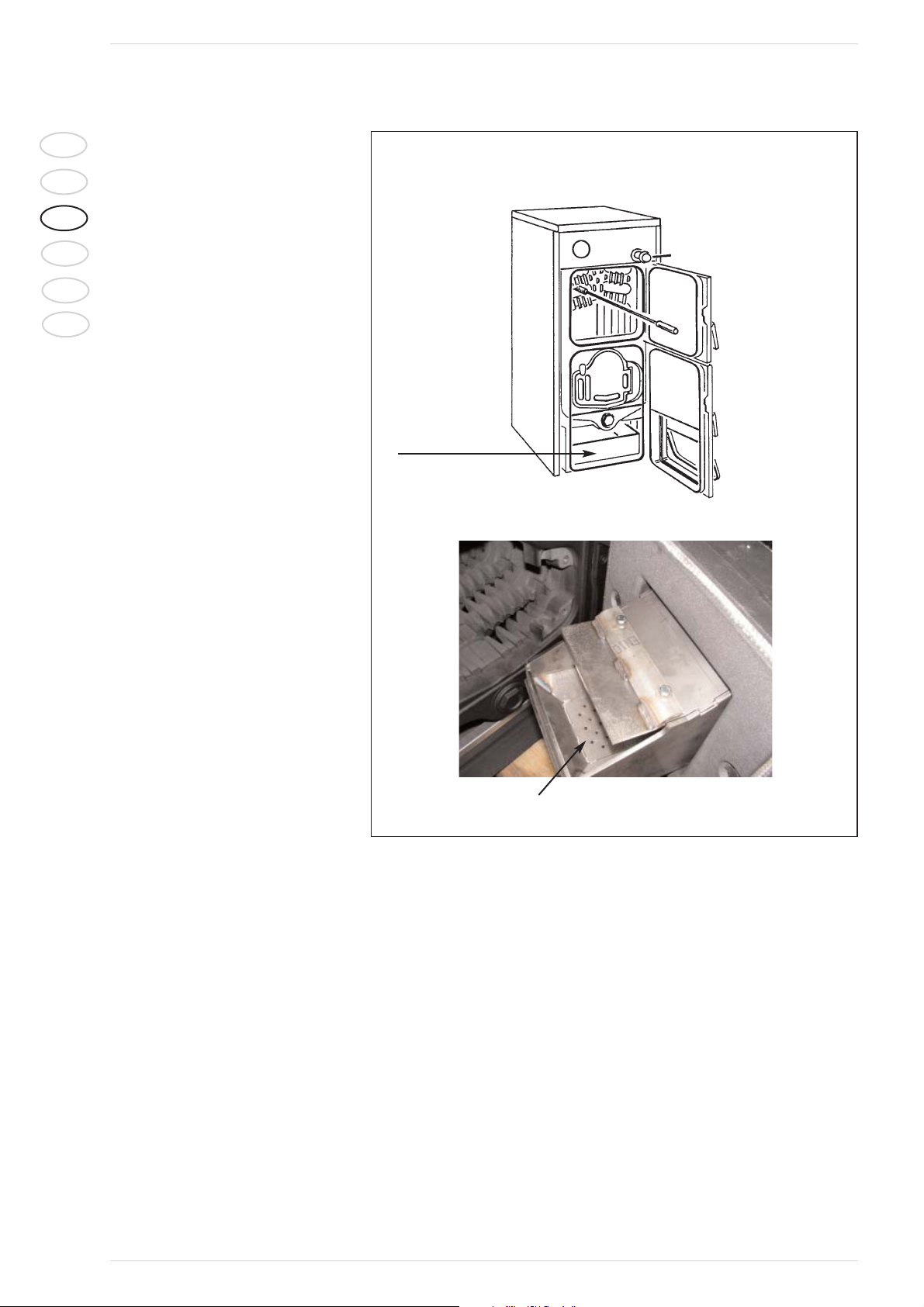
2.3.10 CLEANING (FIG. 19)
Cleaning operations must be carried out at
regular intervals and only when the boiler is
cold.
Combustion residuals collect in the removable drawer that must be emptied before
starting the boiler. To remove all combustion residuals, use an ordinary aspirator
and verify that all the ashes inside the combustion chamber have been completely
removed. The aspirator can also be used to
clean the pellet grille.
To clean the fume ducts inside the boiler
body, use a wiper.
ATTENTION: if the generator is switched
off for long periods of time (above 15
days), it is necessary to empty the 200 500 dm
3
pellet container in order to prevent the pellets from absorbing excessive
humidity, which could affect the operation
of the boiler. A high amount of humidity in
the pellets could cause them to pulverize,
increase the amount of residuals in the
brazier and obstruct the pellet feeding
system.
2.3.11 ANNUAL MAINTENANCE
For optimum performance, it is advisable
to have the boiler inspected accurately
and thoroughly by qualified personnel at
least once every season.
Before performing maintenance operations, verify that the boiler is cold and has
been disconnected from the mains.
Fig. 19
Removable
drawer
Pellet grille
 Loading...