

Page 1

SIM340DZ EVB User Guide
Page 2

SIM340DZ EVB User Guide
Document Name:
Version:
Date: 2006-07-21
DocId:
Status: Release
General Notes
Simcom offers this information as a service to its customers, to support application and
engineering efforts that use the products designed by Simcom. The information
provided is based upon requirements specifically provided to Simcom by the customers.
Simcom has not undertaken any independent search for additional relevant information,
including any information that may be in the customer’s possession. Furthermore,
system validation of this product designed by Simcom within a larger electronic system
remains the responsibility of the customer or the customer’s system integrator. All
specifications supplied herein are subject to change.
Copyright
This document contains proprietary technical information which is the property of
SIMCOM Limited., copying of this document and giving it to others and the using or
communication of the contents thereof, are forbidden without express authority.
Offenders are liable to the payment of damages. All rights reserved in the event of grant
of a patent or the registration of a utility model or design. All specification supplied
herein are subject to change without notice at any time.
Copyright © SIMCOM Limited. 2006
SIM340DZ EVB User Guide
2.01
SIM340DZ-EVB_UGD_V2.01
SIM340DZ-EVB_UGD_V2.01 Page 2 of 19
Page 3

SIM340DZ EVB User Guide
Contents
Contents ............................................................................................................................................3
Version History .................................................................................................................................4
1. SIM340DZ EVB...........................................................................................................................5
2. EVB accessory..............................................................................................................................7
3. Accessory Interface.......................................................................................................................8
3.1 Power Interface ................................................................................................................... 8
3.2 Audio Interface....................................................................................................................9
3.3 SIM card interface.............................................................................................................10
3.4 Antenna Interface ..............................................................................................................10
3.5 RS232 Interface.................................................................................................................11
3.6 Operating Status LED.......................................................................................................12
4. T est Interface...............................................................................................................................13
4.1 Serial Interface..................................................................................................................13
4.2 J2---GPIO..........................................................................................................................14
4.3 J3---LCD & I/O.................................................................................................................15
5. EVB and accessory equipment....................................................................................................16
6. Illustration:..................................................................................................................................16
6.1 Running:............................................................................................................................16
6.2 Connecting Net and calling...............................................................................................17
6.3 Downloading.....................................................................................................................17
6.4 Turns off............................................................................................................................17
6.5 Charging............................................................................................................................17
7. 60 PIN assignment of DIP connector of EVB board...................................................................18
Figure Index
FIGURE 1: EVB TOP VIEW...................................................................................................................5
FIGURE 2: EVB BOTTOM VIEW..........................................................................................................6
FIGURE 3: EVB ACCESSORY...............................................................................................................7
FIGURE 4: POWER INTERFACE..........................................................................................................8
FIGURE 5: AUDIO INTERFACE ...........................................................................................................9
FIGURE 6: SIM CARD INTERFACE...................................................................................................10
FIGURE 7: ANTENNA INTERF ACE...................................................................................................10
FIGURE 8: SERIAL PORTS..................................................................................................................11
FIGURE 9: STATUSLED ......................................................................................................................12
FIGURE 10: TEST INTERFACE OVERVIEW.....................................................................................13
FIGURE 11: J1 INTERFACE.................................................................................................................13
FIGURE 12: J2 INTERFAC E................................................................................................................14
FIGURE 13: J3 INTERFAC E................................................................................................................15
FIGURE 14: EVB AND ACCESSORY EQUIPMENT .........................................................................16
FIGURE 15: DIP CONNECTOR OF EVB BOARD.............................................................................18
SIM340DZ-EVB_UGD_V2.01 Page 3 of 19
Page 4

SIM340DZ EVB User Guide
Version History
Data Version Description of change Author
2006-4-12 1.00 Origin Qianhuai
2006-6-12 1.01 Update the figure in the document Qianhuai
2006-7-21 2.01
SCOPE
This document give the usage of SIM340DZ EVB, user can get useful info about the SIM340DZ
EVB quickly through this document.
This document is subject to change without notice at any time.
SIM340DZ-EVB_UGD_V2.01 Page 4 of 19
Page 5
SIM340DZ EVB User Guide
1. SIM340DZ EVB
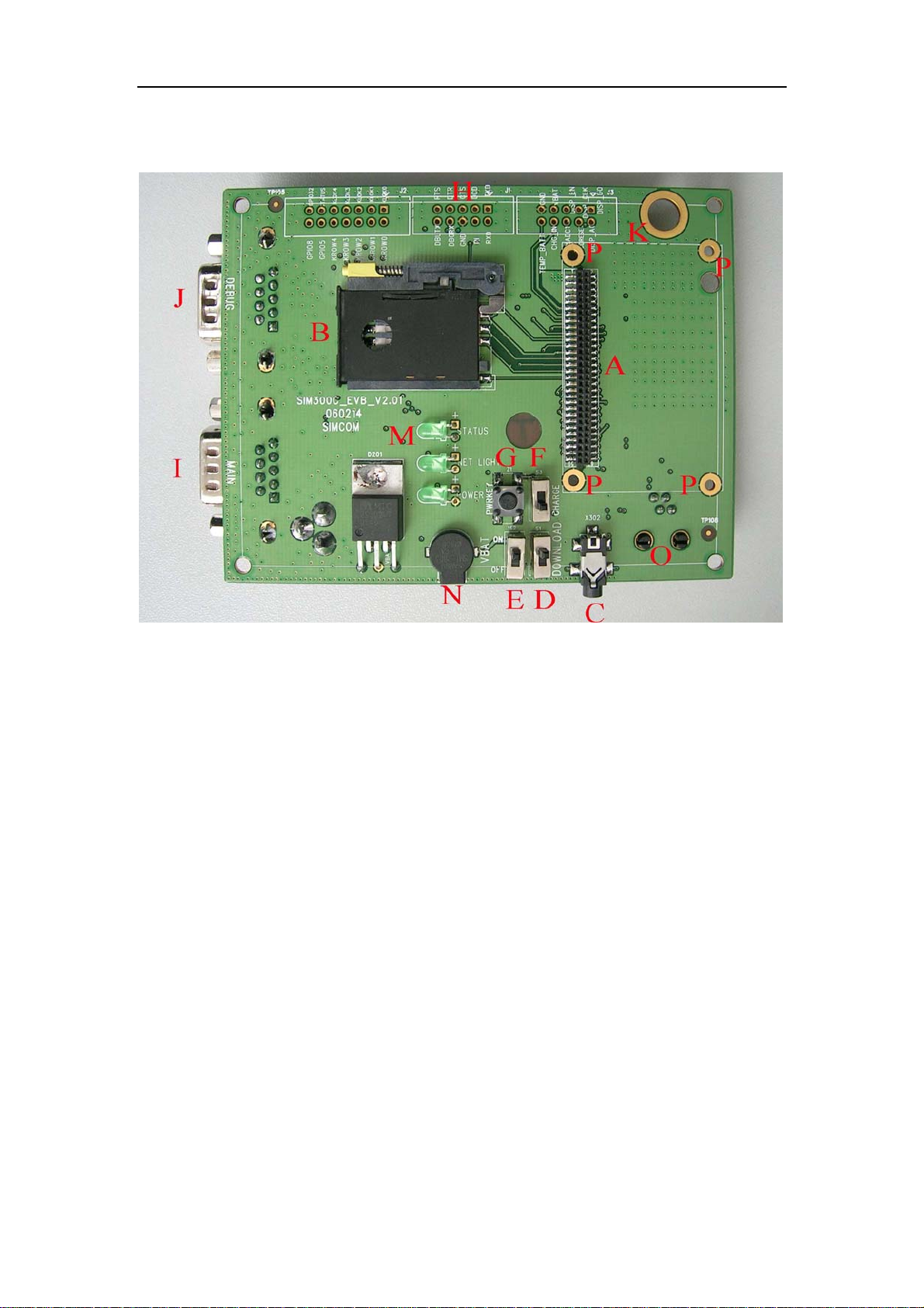
Figure 1: EVB TOP view
SIM340DZ-EVB_UGD_V2.01 Page 5 of 19
Page 6
SIM340DZ EVB User Guide
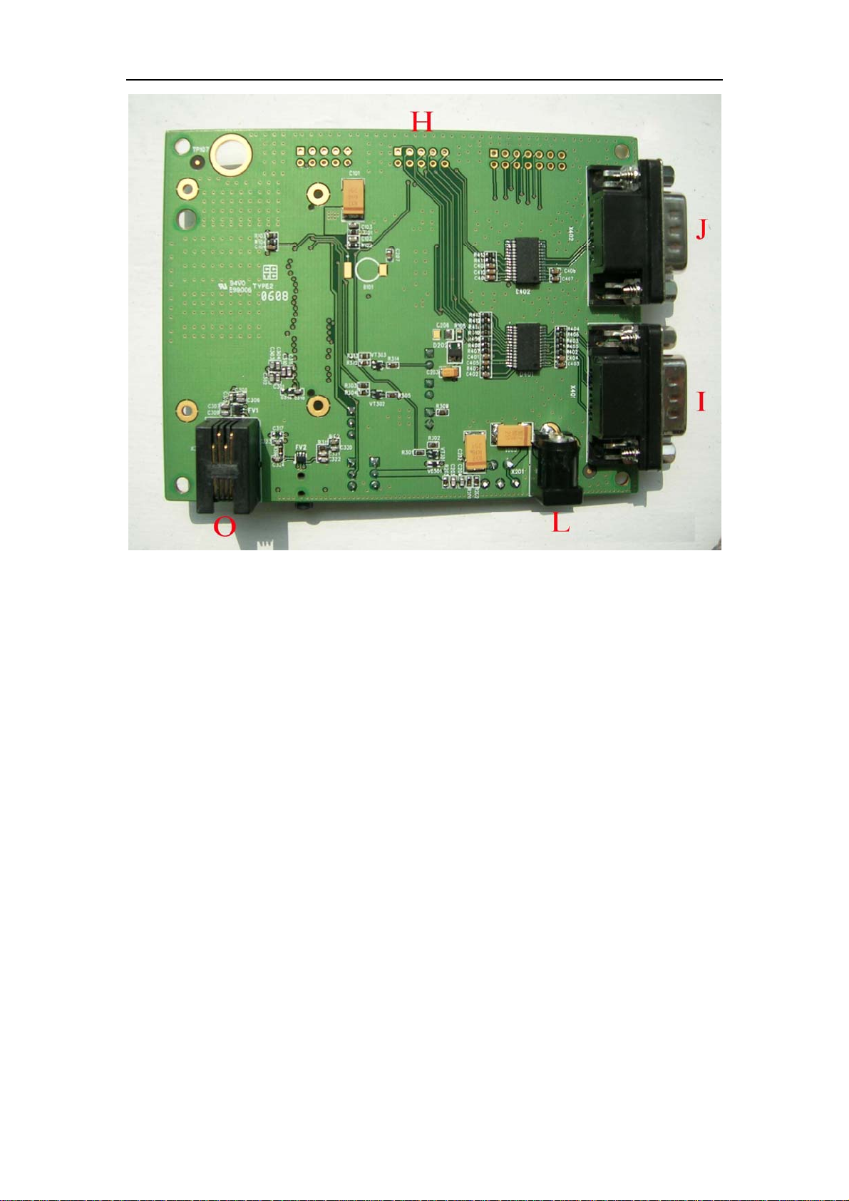
Figure 2: EVB BOTTOM view
A: SIM340DTE with SIM340DZ module interface
B: SIM card interface
C: headset interface
D: Download switch, turn on or off download function
E: VBAT switch, switch the voltage source from the adaptor or external battery
F: VCHG ON/OFF control (shifter S3)
G: PWRKEY key, turn on or turn off SIM340DZ
H: main and debug serial port
I: MAIN serial port for downloading, AT command transmiting, data exchanging
J: DEBUG serial port
L: source adapter interface
M: light
N: buzzer
O: headphones interface
Operating of module may interfere with medical devices like hearing aides and pacemakers.
Please always keep the module more than 20 centimeters away from such medical devices when
the module is powered on.
The module has been tested and found to comply with the limits for a Class B digital device,
pursuant to part 15 of the FCC Rules. These limits are designed to provide reasonable protection
against harmful interference in a residential installation.
SIM340DZ-EVB_UGD_V2.01 Page 6 of 19
Page 7
SIM340DZ EVB User Guide
The module generates, uses and can radiate radio frequency energy and ,if not installed and used
In accordance with the instructions, may cause harmful interference to radio communications.
However, there is no guarantee that interference will not occur in a particular installation. If the
module does cause harmful interference to radio or television reception, which can be determined
by turning the equipment off and on , the user is encouraged to try to correct the interference by
one or more of the following measures:
------Reorient or relocate the receiving antenna.
------Increase the separation between the equipment and receiver.
------Connect the equipment into an outlet on a circuit different from that to which the
receiver is connected.
-------Consult the dealer or an experienced radio technician for help
This device complies with part 15 of the FCC Rules. Operation is subject to the following two
conditions:
(1) This device may not cause harmful interference;
(2) This device must accept any interference received, including interference that may cause
undesired operation.
2. EVB accessory
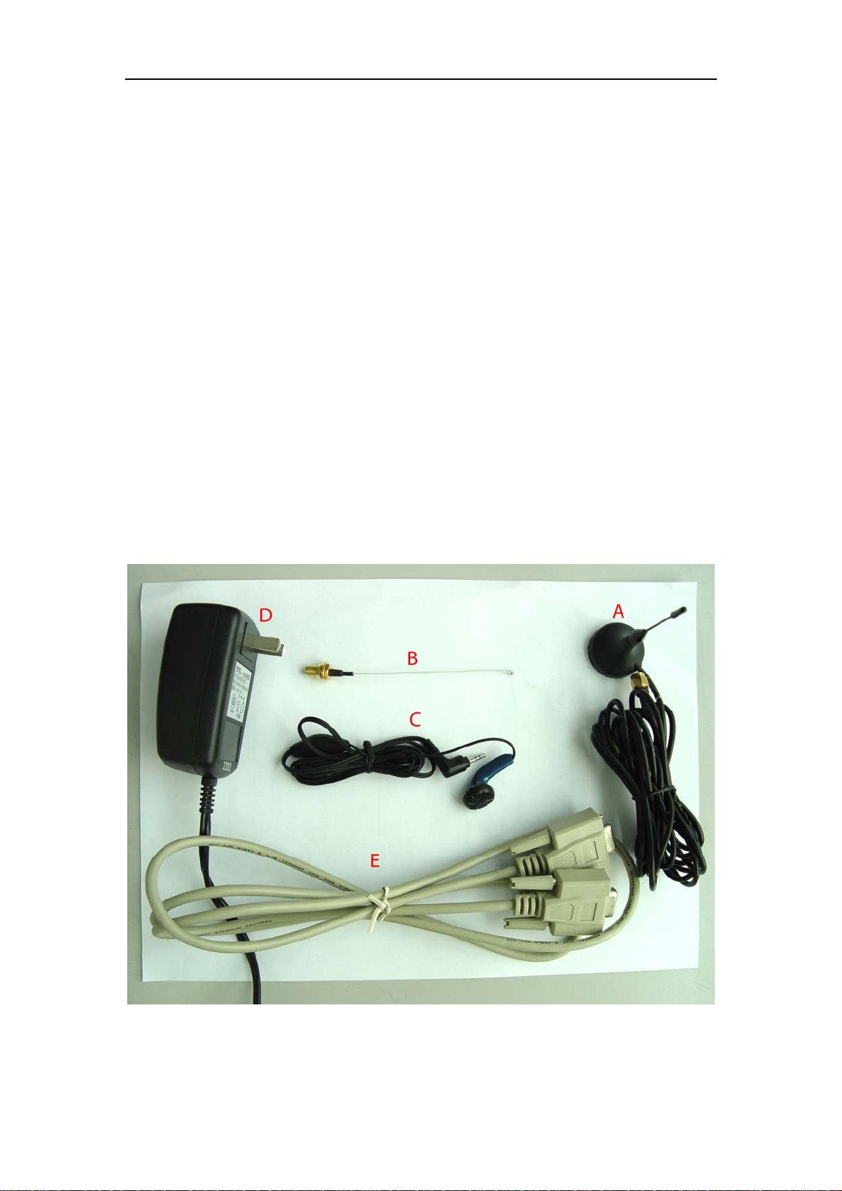
Figure 3: EVB accessory
A: antenna
SIM340DZ-EVB_UGD_V2.01 Page 7 of 19
Page 8
SIM340DZ EVB User Guide
B: antenna transmit line
C: headset
D: 5V DC source adapter
E: serial port line
3. Accessory Interface
3.1 Power Interface
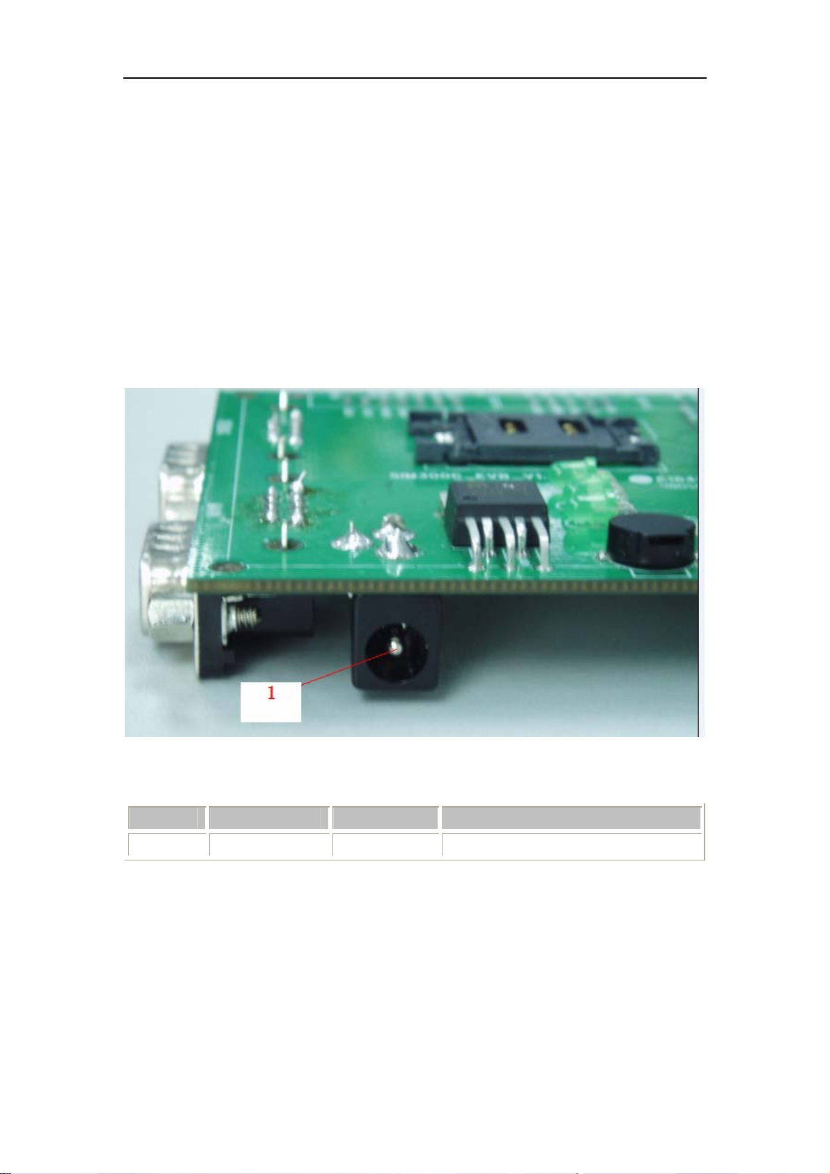
Figure 4: Power Interface
Pin Signal I/O Description
1 Adapter input I 5V/2.5A DC source input
SIM340DZ-EVB_UGD_V2.01 Page 8 of 19
Page 9

SIM340DZ EVB User Guide
3.2 Audio Interface
Figure 5: Audio Interface
Headset interface:
Pin Signal I/O Description
1 MIC1P I Positive microphone input
2 SPK1P O Positive receiver output
3 SPK1N O Negative receiver output
4 MIC1N I Negative microphone input
Earphone interface:
Pin Signal Input/Output Description
5 MIC2P&SPK2P I/O Auxiliary positive input and output
SIM340DZ-EVB_UGD_V2.01 Page 9 of 19
Page 10
SIM340DZ EVB User Guide
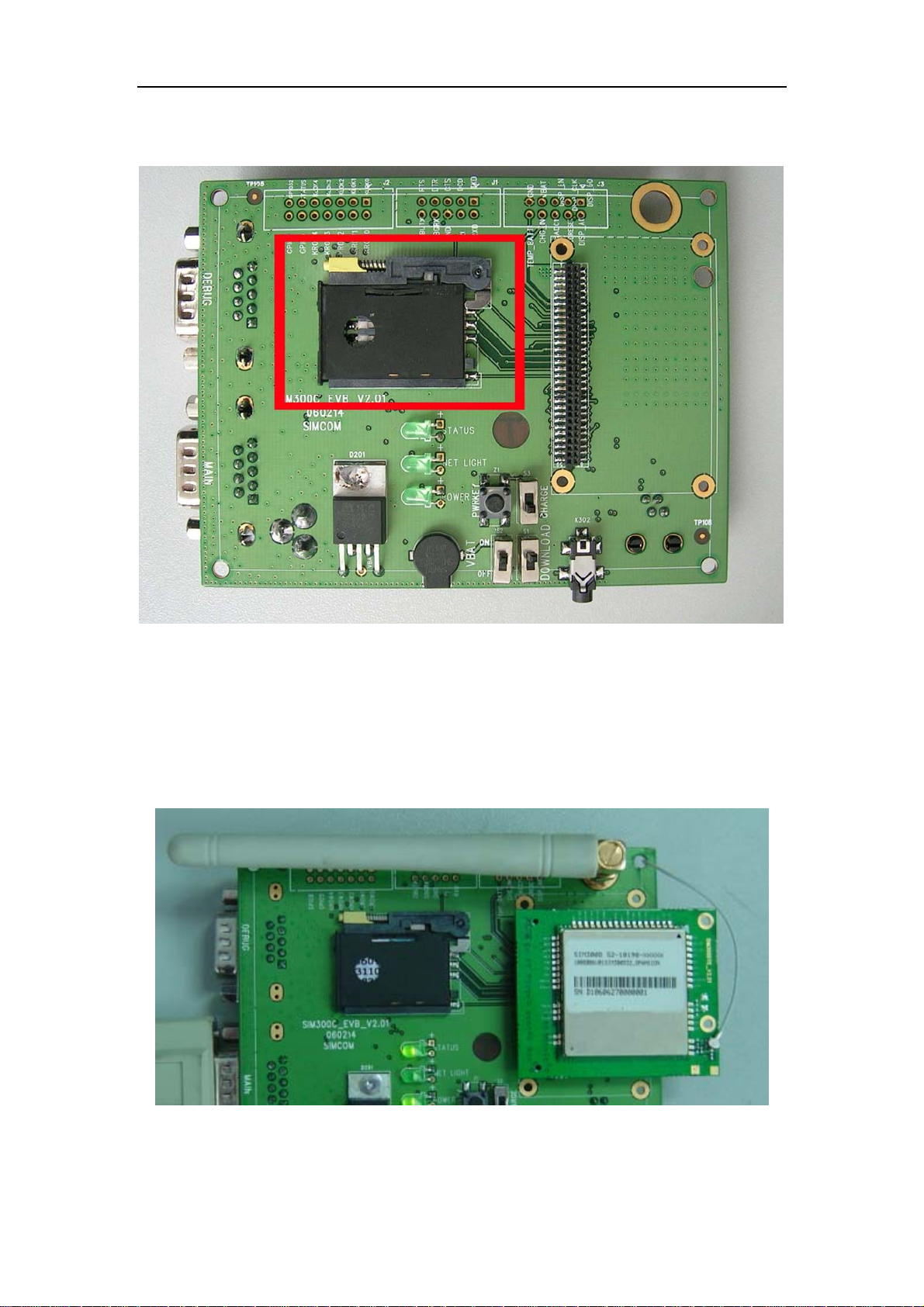
3.3 SIM card interface
3.4 Antenna Interface
Figure 6: SIM card interface
Figure 7: Antenna Interface
SIM340DZ-EVB_UGD_V2.01 Page 10 of 19
Page 11
SIM340DZ EVB User Guide
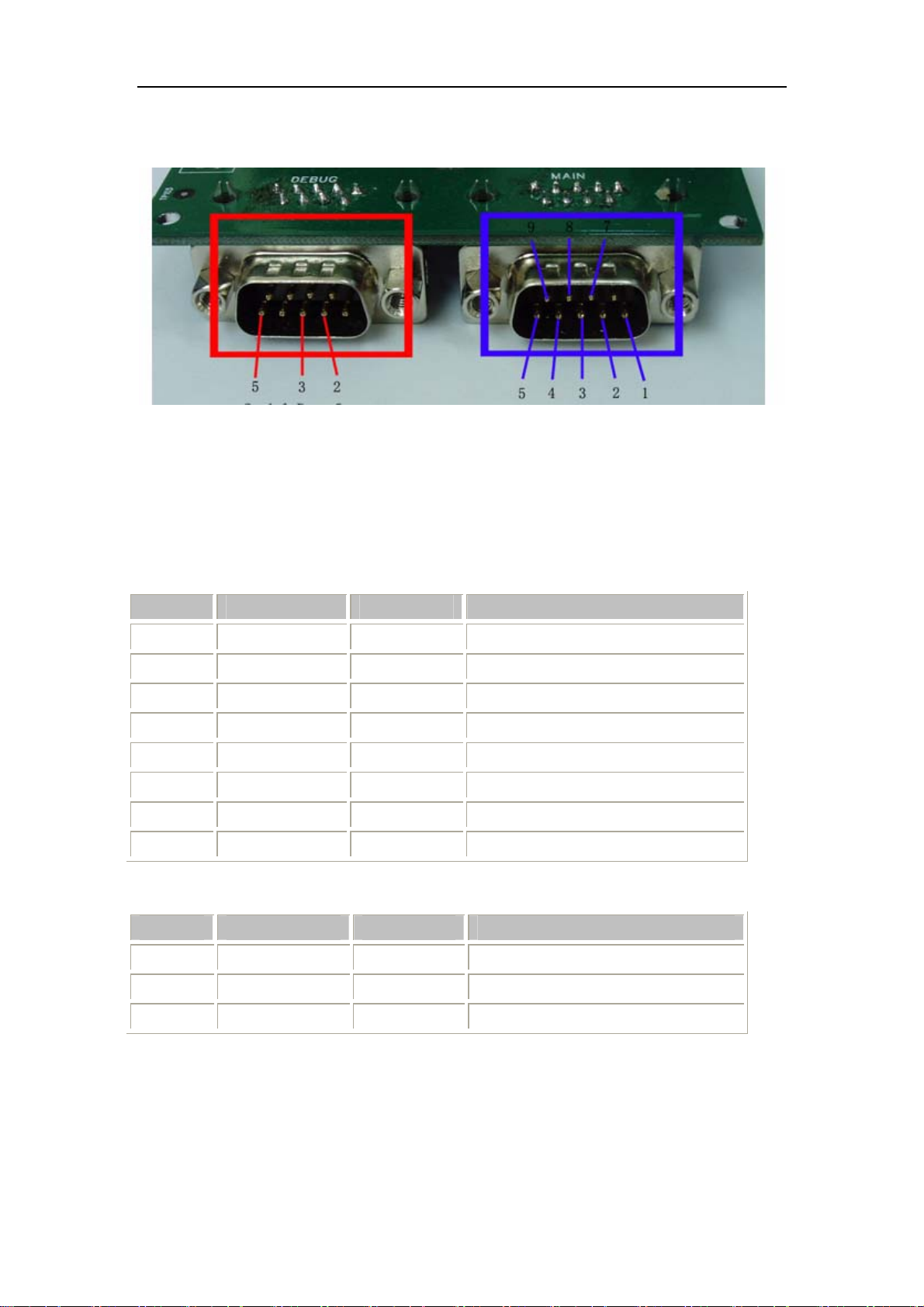
3.5 RS232 Interface
Figure 8: Serial Ports
Serial Port 1——MAIN Interface
Serial Port 2——DEGUG Interface
Main Interface:
Pin Signal I/O Description
1 DCD O Data carrier detection
2 TXD O Transmit data
3 RXD I Receive data
4 DTR I Data T erm inal Ready
5 GND GND
7 RTS I Request to Send
8 CTS O Clear to Send
9 RI O Ring Indicator
Debug Interface:
Pin Signal I/O Description
2 DEBUG_TX O Transmit data
3 DEBUG_RX I Receive data
5 GND GND
SIM340DZ-EVB_UGD_V2.01 Page 11 of 19
Page 12
SIM340DZ EVB User Guide
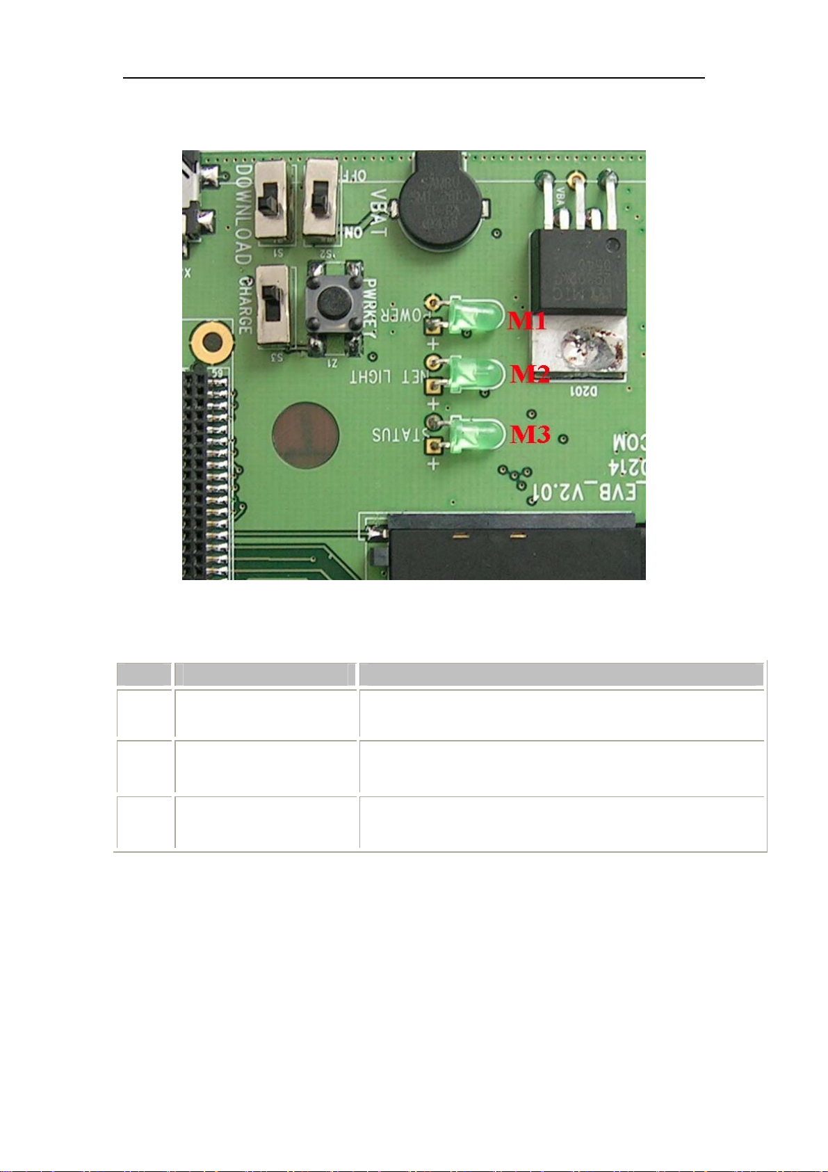
3.6 Operating Status LED
Figure 9: StatusLED
Working state of status LED as list:
Name Description STATUS
M1 VBAT ON/OFF indicator
M2 GSM_NET status indicator
M3 GSM part status indicator
Bright:VBAT ON;
Extinct: VBAT OFF
Blinking at a certain frequency according various GSM net status
Bright: Module runs normally
Extinct: System is powered down or module runs
unconventionally
SIM340DZ-EVB_UGD_V2.01 Page 12 of 19
Page 13
SIM340DZ EVB User Guide
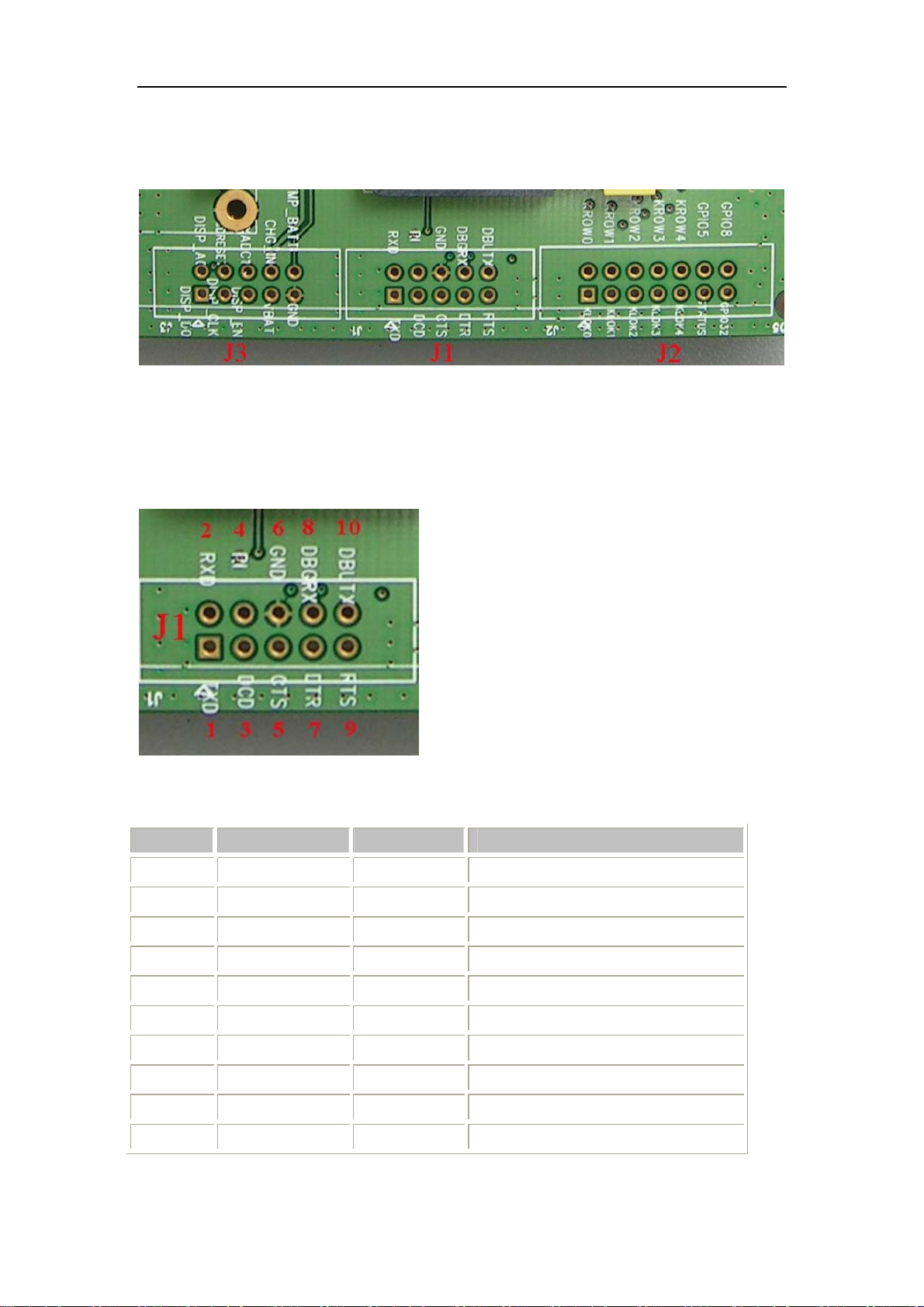
4. Test Interface
Figure 10: Test interface overview
4.1 Serial Interface
J1---RS232 Interface
Figure 11: J1 Interface
RS232 Interface Pin List:
Pin Signal I/O Description
1 TXD O Transmit data
2 RXD I Receive data
3 DCD O Data carrier detection
4 RI O Ring Indicator
5 CTS O Clear to Send
6 GND GND
7 DTR I Data T erm inal Ready
8 DEBUG_RX I Receive data
9 RTS I Request to Send
10 DEBUG_TX O Transmit data
SIM340DZ-EVB_UGD_V2.01 Page 13 of 19
Page 14
SIM340DZ EVB User Guide
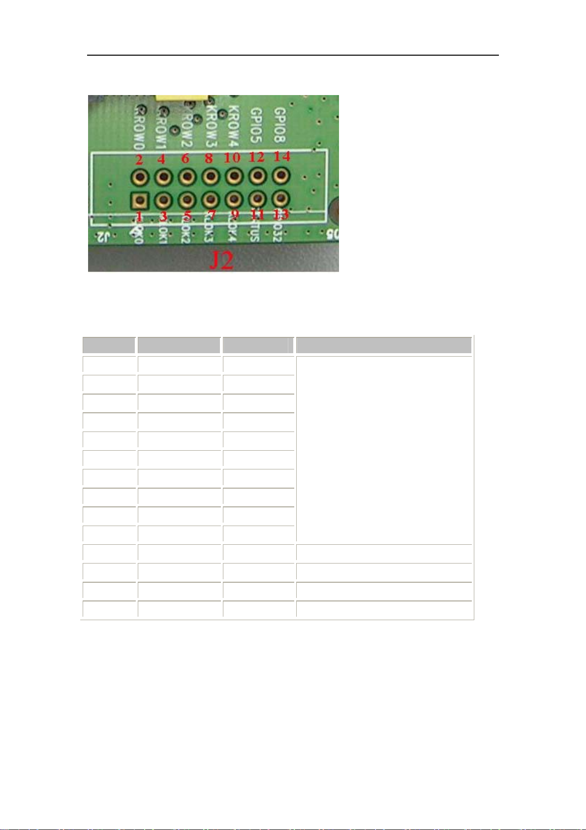
4.2 J2---GPIO
Figure 12: J2 Interface
KEY & CTRL Pin List
Pin Signal I/O Description
1 NC
2 KROW0 I
3 NC
4 NC
5 NC
6 NC
7 NC
8 NC
9 NC
10 NC
11 STATUS O status of module :on or off
12 NC
13 NC
14 GPIO8 O Control signal of BUZZER
Keypad array interface
SIM340DZ-EVB_UGD_V2.01 Page 14 of 19
Page 15
SIM340DZ EVB User Guide
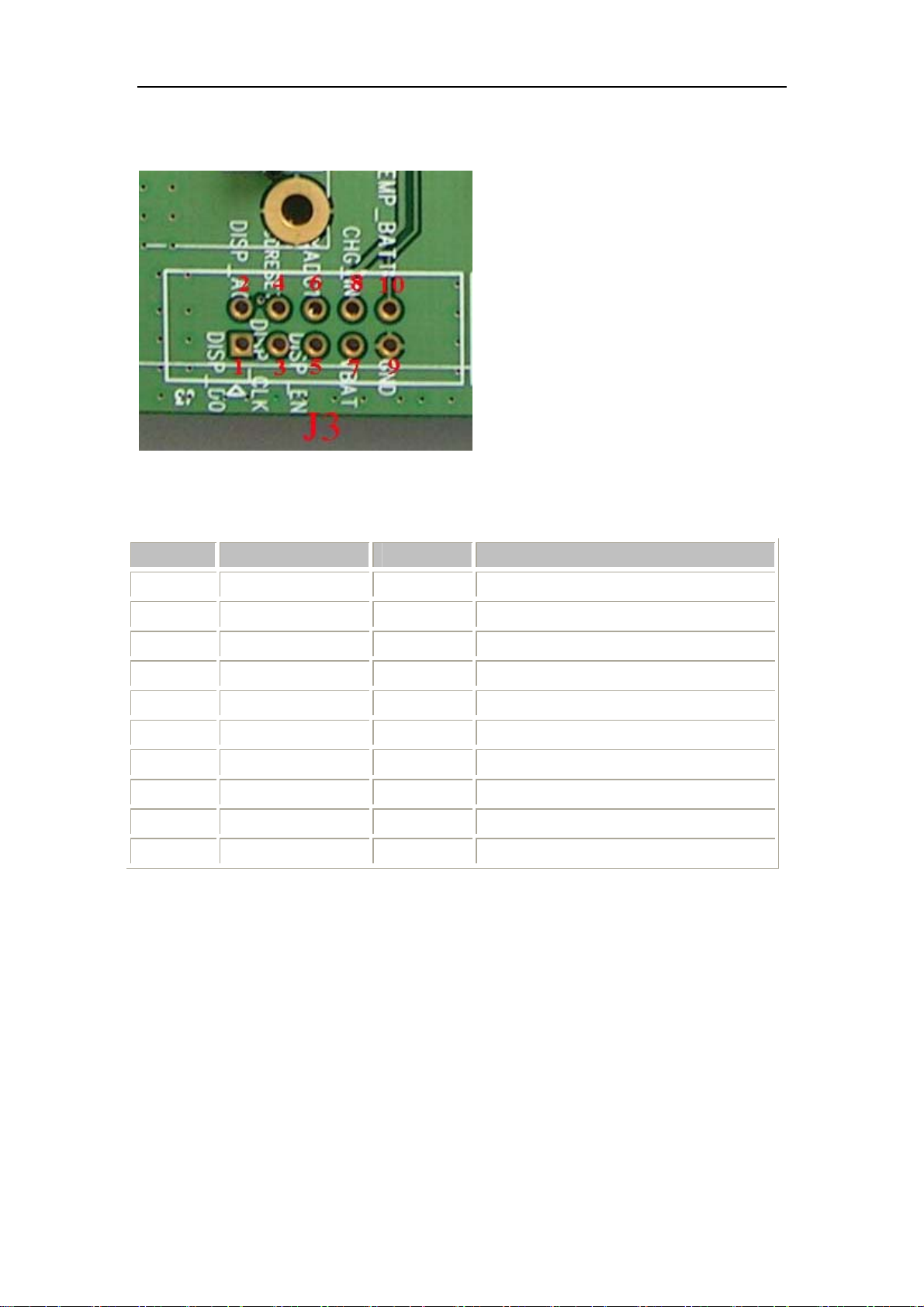
4.3 J3---LCD & I/O
Figure 13: J3 Interface
LCD & I/O Interface Pin List:
Pin Signal I/O Description
1 DISP_D0 I/O Display data line
2 DISP_A0 O Display data or address select
3 DISP_CLK O Display clock output
4 NC
5 DISP_EN O Display enable output
6 AUXADC1 I Adc input
7 VBAT I VBAT
8 CHG_IN I Charger Input
9 GND Ground
10 TEMP I For measure of the battery temperature
SIM340DZ-EVB_UGD_V2.01 Page 15 of 19
Page 16
SIM340DZ EVB User Guide
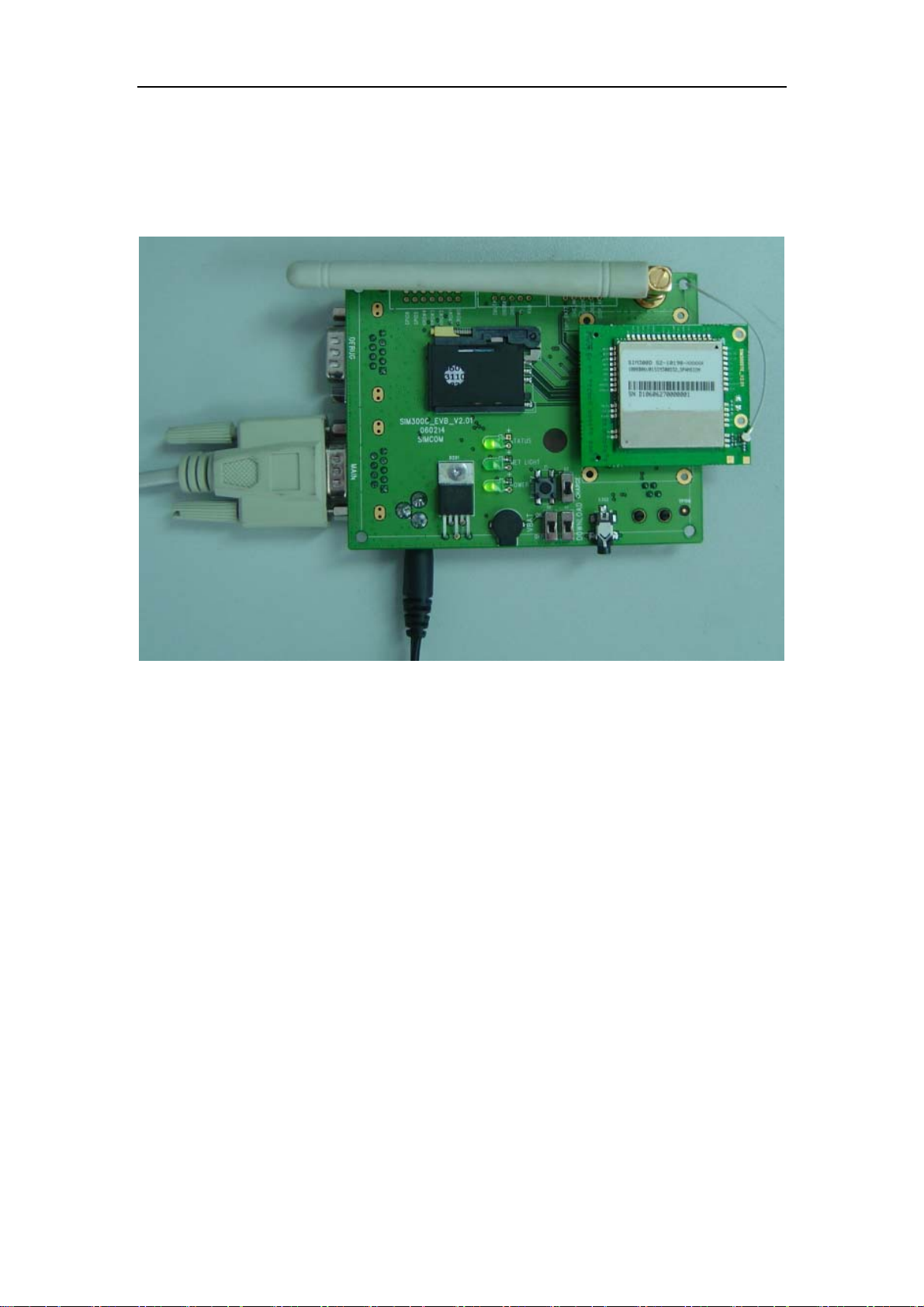
5. EVB and accessory equipment
At normal circumstance, the EVB and its accessory are equipped as the Figure 14
Figure 14: EVB and accessory equipment
6. Illustration:
6.1 Running:
(1) Connect the SIM340DTE with SIM340DZ module to the 60pins connector on
SIM340DZ EVB, inserting 5V direct current source adapter, switching the S1 switch on
off state, S2 switch on ON state;
(2) Press the PWRKEY for about 1 second, and then SIM340DZ module begins running.
You can see the light M2 on the EVB flashing at a certain frequency. By the state, you can
judge whether the EVB and SIM340DZ can run or not. No function and test can be executed
when we have not connected necessary accessories.
SIM340DZ-EVB_UGD_V2.01 Page 16 of 19
Page 17

SIM340DZ EVB User Guide
6.2 Connecting Net and calling
(1) connect the serial port line to the MAIN serial port, open the HyperTerminal(AT
command windows) on your Personal computer, the location of the HyperTerminal in
windows2000 is START→ accessory→ communication→ HyperTerminal. Set correct
Baud Rate and COM number. The Baud Rate of SIM340DZ is 115200, and the COM
number based on which USB port your serial port line insert in, you should select such
as COM3 or COM4 etc.
(2) Connect the antenna to the SIM340DTE with SIM340DZ module using an antenna
transmit line, insert SIM card into the SIM card interface, insert headphones or headset
into its interface.
(3) Act on the step of
AT command in the HyperTerminal, and then the SIM340DZ module will execute its
corresponding function.
running which mentioned above, power on the system, typing the
6.3 Downloading
Connect the serial port line to the MAIN serial port, connect the direct current source
adapter, run the download program and press the START key, then switch the S1 switch on ON
state, S2 switch on ON state, then EVB provide the function of downloading.
6.4 Turns off
Turn off SIM340DZ module: press the PWRKEY for about 1 second, SIM340DZ module
will be turned off.
6.5 Charging
Connect the SIM340DTE with SIM340DZ module to the 60pin connector interface and
the external battery to charging interface, which have been provided on the EVB. Insert the
direct current source adapter; switch shifter S2 on the OFF state, shifter S3 on the ON state,
then the SIM340DZ will go to the charging state.
SIM340DZ-EVB_UGD_V2.01 Page 17 of 19
Page 18
SIM340DZ EVB User Guide
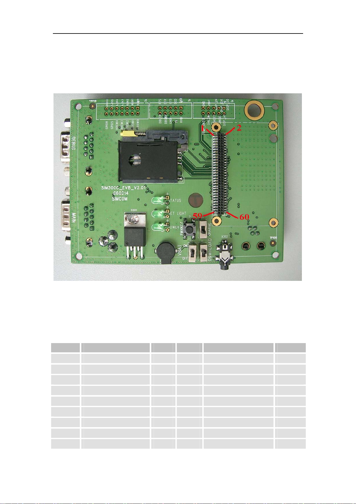
7. 60 PIN assignment of DIP connector of EVB board
Figure 15: DIP connector of EVB board
Connection diagrams
PIN NO. PIN NAME I/O PIN NO. PIN NAME I/O
2
4
6
8
10
12
14
16
18
GND
GND
GND
GND
GND
ADC1 I
VRTC I
NETLIGHT O
NC
1
3
5
7
9
11
13
15
17
VBAT I
VBAT I
VBAT I
VBAT I
VBAT I
CHG_IN I
TEMP_BAT I
NC O
PWRKEY I
SIM340DZ-EVB_UGD_V2.01 Page 18 of 19
Page 19

SIM340DZ EVB User Guide
20
22
24
26
28
30
32
34
36
38
40
42
44
46
48
50
52
NC
NC
NC
NC
KROW0 I
NC
NC
NC
NC
SPI_EN O
SPI_CLK O
SPI_DO I/O
SPI_AO O
NC
DBGRX I
DBGTX O
AGND
19
21
23
25
27
29
31
33
35
37
39
41
43
45
47
49
51
ST ATUS O
NC
GPIO8 I/O
VSIM O
SIM_RST O
SIM_I/O I/O
SIM_CLK O
SIM_PRESENT I
NC
DCD O
DTR I
RXD I
TXD O
RTS I
CTS O
RI O
AGND
54
56
58
60
MIC1P I
MIC1N I
MIC2P I
MIC2N I
53
55
57
59
SPK1P O
SPK1N O
SPK2P O
SPK2N O
SIM340DZ-EVB_UGD_V2.01 Page 19 of 19
 Loading...