

Page 1

IONIZATION SOLUTIONS
Ionizing Bar System
scorpION3
User’s Manual
TM
Page 2

About Simco-Ion
Simco-Ion develops, manufactures, and markets system solutions
to manage electrostatic charge. As the world's largest provider of
electrostatics management products and services, Simco-Ion
improves its customers' business results by providing a total
solution to their electrostatic discharge and electromagnetic
interference challenges. Simco-Ion Technology Group is a division
of Illinois Tool Works (ITW), located in Alameda, California. For
more information about Simco-Ion visit www.simco-ion.com or call
800-367-2452. Simco-Ion is ISO 9001.
© 2014 Simco-Ion
scorpION3 5200969 Rev 4
Page 3

Important Safety Information
Carefully read the following safety information before
installing or operating the equipment. Failure to follow
these safety warnings could result in damage to your
ionization system and/or voiding the product warranty.
Read the complete Instruction Manual before proceeding with
installation or operation. Failure to follow instructions may result
in damage to the scorpION3 system or user supplied power
sources.
When this unit is supplied with the AC adapter, the adapter must
be used with a 3-prong grounding plug. The adapter must be
connected to a properly wired and grounded receptacle. Do not
defeat the electrical ground. Grounding and proper wiring are
required for operation.
User supplied 24 VDC power must conform to the electrical
characteristics as outlined in this document. Incorrect power
connections to the bar can result in damage to the scorpION3
bar and/or to user power supply.
User connections to the fault output must conform to the limita-
tions outlined for the opto-isolated transistor. Incorrect connections to the fault interface can result in damage to the
scorpION3 bar.
Interconnection between bars should be made only with Simco-
Ion supplied interconnect wiring.
A factory-qualified service technician must perform component
service and repairs.
scorpION3 5200969 Rev 4
Page 4

Informations de Sécurité Importantes
Lisez attentivement les consignes de sécurité
suivantes avant d'installer ou d'utiliser l'équipement. Le
non-respect de ces avertissements peut entraîner des
dommages à votre système d'ionisation et/ou d'annuler
la garantie du produit.
Lecture complète du Manuel d'utilisation avant de procéder à
l'installation ou au fonctionnement. Le non-respect de ces
instructions peut entraîner des dommages au scorpion3
système ou utilisateur fourni sources d'alimentation.
Quand cette unité est fourni avec l'adaptateur secteur, la carte
doit être utilisée avec un 3-broches fiche de mise à la terre. La
carte doit être connectée à un correctement câblé et mis à la
terre prise. Ne pas défaire la mise à la terre électrique. La mise
à la terre et le câblage correct sont requis pour l'opération.
Utilisateur fourni alimentation 24 VCC doit être conforme aux
caractéristiques électriques tel que décrit dans le présent document. Mauvaise connexion de l'alimentation de la barre peut
entraîner des dommages au scorpion3 bar et/ou à l'utilisateur
d'alimentation.
Connexions de l'utilisateur à la sortie de panne doivent être
conformes aux limites décrites pour l'opto-isolées le transistor.
Connexions incorrectes pour le défaut interface peut entraîner
des dommages au scorpion3 bar.
L'interconnexion entre les barres doivent être effectuées
uniquement avec Simco-Ion fourni câblage d'interconnexion.
N'insérez pas d'objets dans l'unité de grilles d'entrée ou de
sortie en cours de fonctionnement. Dommage pour l'ioniseur et/
ou peut entraîner des blessures graves.
scorpION3 5200969 Rev 4
Page 5

Contents
1 Description .......................................................................... 1
1.1 scorpION3 Ionizing Bar System............................................................... 2
1.2 Features................................................................................................... 4
2 Installation ........................................................................... 5
2.1 Mounting Considerations .........................................................................6
2.2 Wiring Considerations..............................................................................7
2.3 Bar Configuration.................................................................................. 10
2.4 Multi-Bar Installations............................................................................. 11
2.5 Air Assist (optional)................................................................................ 12
2.6 MMI (Man Machine Interface)................................................................ 13
2.7 CI (Computer Interface) ......................................................................... 21
3 Operation ........................................................................... 25
3.1 Settings.................................................................................................. 26
4 Maintenance ...................................................................... 29
4.1 Cleaning & Calibration ........................................................................... 30
4.2 Cleaning the Emitters............................................................................. 31
4.3 System Calibration.................................................................................34
4.4 System Diagnostics ............................................................................... 35
5 Specifications.................................................................... 37
6 Warranty & Service .......................................................... 43
scorpION3 5200969 Rev 4
Page 6

Description
1.1 scorpION3 Ionizing Bar System
1.2 Features
1
scorpION3 5200969 Rev 4 1
Page 7
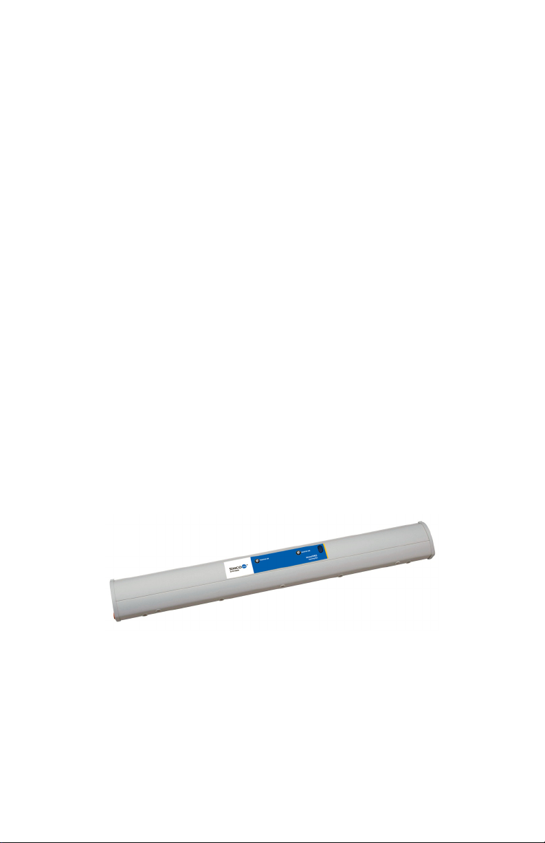
1.1 scorpION3 Ionizing Bar System
The scorpION3 bar system is an ionization solution for work areas
and OEM mini-environments. Intended for cleanroom applications,
the bar is available with tungsten or single crystal silicon emitter
points for the cleanest ionization available. scorpION3’s flexible
design allows independent or dependent operation of multiple bars
in a system. 24 VDC operation allows easy installation in OEM
semiconductor and wafer processing tools. Set-up and adjustment
is easy with the two-way communication provided by the scorpION3
MMI man machine interface or CI computer interface. The
computer interface also offers real-time monitoring of scorpION3
system performance.
The scorpION3 bar utilizes Simco-Ion’s innovative and effective
microcontroller intelligent ionization technology. The system
provides rapid neutralization of static charges over a localized work
area or a mini environment. It is the most flexible and efficient
system available, capable of eliminating electrostatic discharge
(ESD) and preventing electrostatic attraction (ESA) of particles to
surfaces. The scorpION3’s design allows multiple bars to be
connected together into a system that operates synchronously
without the added expense and installation of a dedicated
controller, adding cost effectiveness to its features.
The scorpION3 bar incorporates integrated total communication
capability. This allows one bar to operate as both an ionization
source and as a controller for additional scorpION3 bars. The
scorpION3 is designed to monitor and maintain critical operating
parameters through the use of its microcontroller, active selfmonitoring, and automatic system correction.
scorpION3 5200969 Rev 4 2
Page 8

A scorpION3 bar may be designated as a master; it will then talk to
the other bars connected to it via integrated RS-485
communication. The master maintains contact with each bar to
synchronize system operations. Individual bars connected in a
system monitor and store their own operating parameters. If a
problem should occur, each bar has the capability to visually
indicate a fault condition and also provide an output that can be
integrated into system control hardware.
Adjustment of ion output and balance can be made to individual
scorpION3 bars via the hand-held MMI module (Man Machine
Interface) which features two-way communication with the bars via
wireless infrared or hardwired RS-485 on a modular cable.
Individual bar addressing ensures adjustment of only the desired
bar. Operating mode and pulse frequency are adjusted at the
individual bar or the master bar depending upon configuration.
The scorpION3 CI (Computer Interface) provides an interface
between the scorpION3 bar system and a personal computer or
local computer network. With Simco-Ion’s interface software, a
user may set-up, monitor or control the scorpION3 bar system from
their computer. The scorpION3 CI provides for communication via
an Ethernet connection.
scorpION3 5200969 Rev 4 3
Page 9

1.2 Features
Low Voltage Bar
• Closed-loop feedback system monitors operating conditions
• Individually adjustable via hand-held MMI (10 unique
addresses are available)
• Replaceable emitters
• Tungsten or single crystal silicon emitter points
• Easy mounting using included hardware
MMI – Handheld Terminal
• Allows addressable control of up to 10 individual bars
• Remotely adjusts ionization parameters for calibration
• Acquires diagnostic information from the system
• Two-way communication enables display of operating status
and system monitoring
• Detects address conflicts on bus, allows user to resolve
CI – Computer Interface
• Provides Ethernet connection for networking
• Remote set-up, monitoring and control
• Connection to other scorpION3 computer interfaces
• Automatically addresses and resolves bar address conflicts
scorpION3 5200969 Rev 4 4
Page 10

Installation
2.1 Mounting Considerations
2.2 Wiring Considerations
2.3 Bar Configuration
2.4 Multi-Bar Installations
2.5 Air Assist (optional)
2.6 MMI (Man Machine Interface)
2.7 CI (Computer Interface)
2
scorpION3 5200969 Rev 4 5
Page 11

2.1 Mounting Considerations
Remove the shipping caps (yellow or orange plastic) from each emitter
before placing ionizer in service. The caps protect the ion emitter points
from damage during shipping and must be removed before operating the
bar.
Prior to powering up a single or multi-bar system, the ionizing bar(s)
should be securely mounted using the provided hardware. If the
scorpION3 bar is mounted using hardware not provided with the
unit, it is important to keep any grounded hardware away from the
emitter tips. Introducing a ground near the emitter tips can affect ion
balance and discharge times. The bar should be installed so no
grounded objects are within 300 mm (12”) of the emitter face of the
bar. For applications with no airflow, the bar should be positioned
centered over the work area or the area where static control is
desired. For fan filter type applications where airflow is present,
location relative to the target is less critical, but for best result the
bar should also be centered over the target area.
scorpION3 5200969 Rev 4 6
Page 12

2.2 Wiring Considerations
The scorpION3 may be configured for independent operation or
configured for multiple bar installations. In multiple bar installations,
one bar may be designated as the master and serve as the system
controller, by assigning it to address 0 (zero).
For installations of up to 3 bars, Simco’s AC adapter power supply
can be utilized. Install all bars and interconnect wiring before
applying power. Plug the adapter power cord into a grounded
electrical outlet of 100 to 240 VAC, 50 or 60 HZ. Connect the
adapter to one of the scorpION3 bars with a modular cable. The
power will automatically be distributed to the other bars in the
‘chain’. The scorpION3 bar has no on/off switch so application of
the 24 VDC to the unit will turn it on and ionization will begin. The
power supply and wiring can be located as desired by the user.
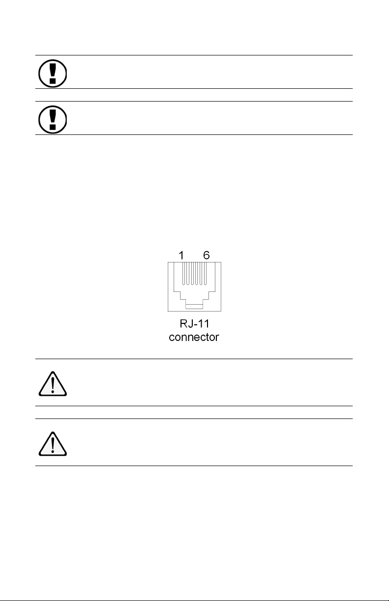
For other installations 24 VDC power can be supplied via the RJ-11
modular connector. Connect pins 1 & 6 to the +24 volt supply
voltage and connect pins 3 & 4 to ground (ground serving as the
return for the supply voltage), see table below. Users connecting to
the scorpION3 in this method must be able to supply 200mA per bar
connected.
scorpION3 5200969 Rev 4 7
Page 13
The scorpION3 is internally fused to protect the user’s power
supply during this type of setup.
Le scorpION3 est à fusible interne afin de protéger l'utilisateur
d'alimentation pendant ce type de configuration.
RJ-11 MODULAR CONNECTOR
PIN NUMBER 1 2 3 4 5 6
CONNECTION +24 VDC N.C. GND GND N.C. +24 VDC
N.C. = No Connection Permitted
Table 1. RJ-11 modular connector user connections
Connections or grounding of pins 2 & 5 on the modular
connector is not permitted and may result in malfunction or
damage to the system.
Connexions ou de mise à la terre de broches 2 & 5 sur le
connecteur modulaire n'est pas autorisé et peut entraîner des
dysfonctionnements ou d'endommager le système.
The fault alarm may be remotely monitored using the fault output
jack on the end of the bar. The output jack is a 3.5 mm (1/8”) mono
phone jack connected to an opto-isolated transistor inside the bar.
The tip of the phone jack is positive (collector) and the sleeve of the
phone jack is negative (emitter). The opto-isolated transistor may
be set normally open (N.O.) or normally closed (N.C.) by changing
scorpION3 5200969 Rev 4 8
Page 14

the Fault Contact setting with the MMI or through configuration
software using the CI.
The fault output transistor may be used to provide switching in order
to drive a variety of low current devices such as LEDs or buzzers,
relays may be used to switch power to higher power devices.
scorpION3 5200969 Rev 4 9
Page 15

2.3 Bar Configuration
The scorpION3 bar has two ionization indicators and a window for
receiving and transmitting commands via IR with the MMI,
incorporated into the scorpION3 face label on the front of the bar.
The indicators have multiple functions. The main function of the
indicator is to illuminate when the high voltage power supply is
activated. A green indicator shows that the bar is operating
normally and no faults are present. A red indicator shows that a
fault is present. The indicators will typically briefly flicker rapidly to
show the receipt of IR commands from the MMI.
Each scorpION3 bar can be assigned a unique address. Addresses
are numbers 0-9 and in multi-bar systems, each bar must have a
unique address. Address “0“ designates a master bar, and allows
the master to send messages to other connected bars for pulse
mode synchronization in multiple bar systems. Note that any bar set
to a non-zero address (and set to slave class), will follow the master
bar pulse rate. When no master bar is present, bars with non-zero
addresses will operate independently.
The bar address is used to ensure that operating adjustments are
made only to the desired bar during set-up and calibration. The bar
address is also used to identify operating parameters and alarms
downloaded from a multi-bar system.
scorpION3 5200969 Rev 4 10
Page 16

2.4 Multi-Bar Installations
For multi-bar installations power is distributed via the RJ-11
connector with 6-conductor modular cable and bars must be
chained together via this connection. Note that in this configuration
adequate current must be available for multiple bars, and the
maximum rating on the DC power supply should not be exceeded.
Bar address numbers should not be duplicated on a given chain.
Having more than one bar “0” will cause communication conflict on
the chain. Address “0” designates the bar as the master and other
bars (if designated as slave) attached to the chain will pulse
synchronously with the master. Where the user supplies
appropriate power to the system, up to 9 bars may be connected to
the master.
In cases where a combination of steady state and pulse coverage
is required with multiple bars, a bar or bars within the system can be
set to the independent class.
scorpION3 5200969 Rev 4 11
Page 17

2.5 Air Assist (optional)
If the scorpION3 bar has Air Assist, the inlet fitting will be located on
the end of the bar with the fault output jack. This fitting is a ¼” quick
connect suitable for typical plastic tubing (1/4”OD polyethylene,
polyurethane, nylon, etc). To make connection with the fitting, insert
the tubing until it stops. To remove tubing from the fitting, depress
the collar on the fitting and pull the tubing out of the fitting.
Compressed air or nitrogen may be used, however, it must be
clean, dry and oil free. While the maximum allowable input pressure
is 700 kPa (100 psi), the recommended nominal operating pressure
is 200 kPa (30 psi).
scorpION3 5200969 Rev 4 12
Page 18

2.6 MMI (Man Machine Interface)
Adjustments to ion balance and ion output can be made to the
scorpION3 bar system by using the hand-held MMI. The MMI
features a 4-line LCD display for setting the bar parameters and
monitoring its operation. The MMI uses an infrared transceiver for
two-way communication with the bar in IR Mode. The MMI also has
RJ-11 connectors that enable it to be connected inline with the bar
system chain for two-way communication by hardwired RS-485 in
Wired Mode.
Infrared communication is established by
pointing the MMI at the IR transceiver on the
bar. The IR transceivers must be aligned to
communicate; the transmission/reception cone
is 15º. Communication can typically take place
at up to 3 meters (10 feet). Successful two-way
communication is indicated by flashing green
indicators on the bar and MMI. If the MMI
indicator flashes red, the MMI was unable to
establish two-way communication and
realignment of the IR transceivers may be
required.
The green indicator on the MMI is also used to indicate if the
selected bar is operating normally, with no fault alarms. If the red
indicator on the MMI is lit, the selected bar is in fault alarm.
Hardwired communication is established by using 6-conductor
modular cable with RJ-11 connectors to insert the MMI at any point
in the chain. Hardwired communication would typically be used
where access to the IR transceiver on the bar was limited or difficult.
Used in this fashion, the MMI taps into the RS-485 communication
lines on the chain and provides feed-thru for the 24 VDC power. To
enable the hardwired communication, it is necessary to turn the
MMI power switch off, connect the MMI to the active bar chain, and
then turn the MMI power switch on. The MMI will sense the power
on the chain and activate the hardwired communication.
scorpION3 5200969 Rev 4 13
Page 19

Turning the power switch off then on at any time will clear any
temporary information entered into the MMI and return the display
to the main menu.
In general, navigating through the system menus is done with the
left/right arrow buttons. The right arrow generally advances to the
next menu and the left arrow generally backs-up to the previous
menu. An MMI Navigation Reference Guide is located in the
appendix; the navigation guide provides a comprehensive listing of
menus available through the MMI.
IR mode is automatically enabled when the MMI is turned on and
not connected to a bar system chain. The first menu allows
selection of adjusting a Bar or Preset. If Bar is selected the MMI will
prompt the user to point the MMI at the bar and press enter. The
MMI and scorpION3 bar feature narrow angle IR transceivers to
minimize undesired IR cross talk. It will be necessary to align the
MMI and bar IR transceivers to ensure communication. Pressing
the Enter button establishes communication with the bar. The green
lights on the bar and the MMI will flicker, indicating successful
communication of the operating parameters. The MMI will display
the bar address and serial number while requesting confirmation
that this is the desired bar.
Confirming the bar address in the IR
mode will enable the MMI to
enter Setting or Diagnostic mode. The operation of these modes
is virtually identical for both the IR
mode and the Wired mode.
Wired mode is automatically enabled when the MMI is turned on
and connected to a bar system chain. The MMI will offer the option
of running Adr Test, an address test mode.
Adr Test (address test) is typically used during the initial set-up of
multi-bar systems; address test is also used when new bars are
added to an existing bar system. Address test evaluates the system
for bar address conflicts (where more than one bar has the same
address number) and guides the user to resolving the address
conflicts by assigning new address numbers to the appropriate
bars. Address conflicts may take place in new systems because the
factory default bar address is “1”. In multi-bar systems this
scorpION3 5200969 Rev 4 14
Page 20

necessitates the assigning of address numbers to avoid duplicate
addresses on a system chain. An exception to this is systems that
have a Computer Interface (CI) on the system chain. If a CI is on
the system chain, it will automatically detect duplicate bar
addresses and assign new address numbers as required.
Advancing into the Wired mode will cause the MMI to search the
scorpION3 system and determine the number of bars present; the
number of bars in the system will be displayed. When the MMI has
searched the system, and determined the proper number of bars in
the system, pressing the right arrow button will advance to the next
menu.
Select Bar, Preset or System Monitor provides for; review and
adjustment of individual bar operating parameters, review and
adjustment of any of the 14 (P1 through P14) preset operating
parameters, or monitoring of the system for operating status and
fault codes. The up/down arrows are used to scroll through bar,
system monitor or the preset numbers and the selection is activated
by pressing the right arrow button.
Select Bar enters a menu where the bar address can be selected
by scrolling through the bars on the system with the up/down arrow
buttons. The bar address number in the system will appear on the
MMI display and the indicator lights on the selected bar will flicker
to confirm which bar in the system is selected. Pressing the right
arrow button when the desired bar is displayed will enter a series of
options for that bar.
The following bar parameters are temporarily stored in the MMI.
The parameters in the MMI will appear as “NEW:”. The parameters
operating in the bar will appear as “SET:”. To transmit the NEW
parameters, press the Enter button. The green lights on the bar and
the MMI will flicker, indicating successful communication of the data
and the “SET” will update to the new setting.
Changed parameters are held in a temporary memory until the
command save settings local to bar is performed. When this
command is performed, the parameters in the bar are synchronized
to the parameters in the MMI and stored in a flash memory in the
scorpION3 5200969 Rev 4 15
Page 21

bar. If save settings local to bar is not performed and power is
removed from the bar, the changes will be lost.
Change Address allows changing of the address number for the
bar, 0 thru 9 are possible bar addresses (active bar addresses will
not be offered). The desired address is selected by up/down arrow
button.
Settings enters a series of menus that use two-way communication
with the bar for adjustment and set-up purposes. The setting mode
may be entered from the Change Address menu. Following are
selections from the Settings menus.
Settings: Advancing from this menu allows the selection of Settings
or Diagnostics. Following are selections from the Settings menus.
Hot Key Tip: Pressing the up arrow and left arrow at the same time
will jump the MMI menu to “Settings”.
• Power (default: on) may be turned on/off (up/down arrows) for
an individual bar in a system.
• Output (default: 50%) may be adjusted for the bar. Using the
up/down arrows adjusts the bar output setting. Output level sets
the ionization output from the ionizer. This value should be set
to the lowest level possible to achieve the desired discharge
time. Higher values of output will result in more ion generation,
which can reduce discharge time, but may result in more
frequent ionizer maintenance. The system will limit maximum
output in cases of long pulse time.
• Pulse/Steady (default: pulse) allows selection of Pulse mode
ionization or SSDC (steady state DC) ionization. In pulse mode
the positive and negative ionization will be energized in
alternating sequence. This provides quicker discharge times for
still air but creates a mildly alternating peak offset voltage.
Steady state DC mode maintains constant output for both the
positive and negative ionization. This is more typically used
where there is airflow to carry the ions to the target.
• Slave/Independent (default: independent) allows for selection
of the bar as a Slave (non-0 address only) or Independent.
scorpION3 5200969 Rev 4 16
Page 22

Slave bars must be in pulse mode and will synchronize their
pulse cycles with the Master bar (0 address) on the system; it
generally takes several minutes for the synchronization to
occur.
• Pulse Time (default: 0.75 seconds) must be set when pulse
mode ionization is selected. The Pulse Time is the duration a
power supply is energized (two pulse times compromise a full
cycle of positive and negative ionization). Using the up/down
arrow adjusts the pulse time in terms of seconds. Generally,
longer pulse times are used in still air where there is relatively
longer distance to the target area. However, the longer pulse
times can create a greater peak offset voltage. If a bar is a
Slave, the Pulse Time can only be set through the Master bar.
Pulse time is ignored when the ionizer is placed in the steady
state mode
• Overlap (default: 30%) sets the overlap of positive and
negative ionization in pulse mode. The system will switch the
power supplies according to the pulse time (the cycle time of
positive and negative ionization does not change), however,
overlap will cause the power supply to extend its run time
determined by the percentage setting. Overlap is beneficial to
reduce the peak offset voltage when operating in the pulse
ionization mode. The system will set a mandatory minimum
overlap in cases of long pulse time. Overlap is not available
when the ionizer is placed in the steady state mode.
• Balance (default: 50/50) adjusting the balance with the up/
down arrows causes the balance ratio to shift by 0.01 steps.
Press the Enter button to transmit the new setting to the bar.
Note: Save settings local to bar
must be performed after
adjustments to balance are made to ensure the changes are
stored in the bar memory.
Hot Key Tip: Pressing the left arrow and right arrow at the same time
will jump the MMI menu to the balance menu.
• Fault Threshold (default 20) is the relative number of times the
microprocessor must encounter a fault condition before it
signals the fault state. Using a threshold to trigger a fault state
reduces nuisance alarms. Increasing the threshold reduces the
scorpION3 5200969 Rev 4 17
Page 23

likelihood of encountering nuisance fault notification.
• HV on w/Fault (default: yes) allows disabling of the ionizer by
turning off the high voltage power supplies if a fault state is
entered.
• Fault Contacts (default: N.O.) allows setting of the Fault
Output opto-isolated transistor as N.O. (normally open) or N.C.
(normally closed).
• Save settings local to bar? (default: no) Saves the changes
made to the operating parameters for the bar into the memory of
the bar. “Y” must be selected with the down arrow, then ENTER
pressed to save settings. The green indicator lights on the bar
and MMI will flicker to confirm saving of settings. This operation
must be performed to ensure the changes will not be lost.
Hot Key Tip: Pressing the up arrow and right arrow at the same time
will jump the MMI menu to “Save settings local to bar”.
• Save as preset? (default: no) This is the option to saving the
changes local to bar. It allows selection of the desired preset
number (P1 through P14) and saving the parameters under this
preset for later downloading into a bar.
• Upload Settings to Bar? (default: no) Uploads the active
preset to a bar. The up/down arrows select the target bar
address. Pressing ENTER uploads the preset to the bar (but
does not save the settings local to bar). In IR mode the MMI will
prompt the user to point the MMI at the bar and press ENTER.
Diagnostic enters a series of menus that use two-way
communication with the bar for diagnostic purposes. The
diagnostic mode may be entered from the Change Address menu.
Following are selections from the Diagnostic menus.
• Feedback is data transmitted back from the bar to the MMI:
Hot Key Tip: Pressing the down arrow and left arrow at the same
time will jump the MMI menu to the Feedback screen.
• PRG Metered feedback ‘Program’ is the input value to the ion
regulating circuitry as established by the microprocessor.
There is a ‘Program’ value for the positive and negative high
scorpION3 5200969 Rev 4 18
Page 24

voltage supplies. The range for this feedback value is from 0 to
1024.
• CUR Metered feedback ‘Current’ is a measure of the output ion
current of the high voltage supply. During normal operation, this
value should be within approximately 10% of the “Program” set
point established by the microprocessor. There is a ‘Current’
value for the positive and negative high voltage supplies. The
range for this feedback value is from 0 to 1024.
• DRV Metered feedback ‘Drive’ indicates the input drive level
into the high voltage supply required to achieve the
programmed level. There is a ‘Drive’ value for the positive and
negative high voltage supplies. The range for this value is from
0 to 1024. Typically this value should be between
approximately 100 and 924.
Fault Code Status Screen appears as follows:
N 0 64:C8 R:000
00 00 00 00 00:
00 00 00 00 00
00 00 00 00 00
‘N’ indicates a normal status. ‘W’ would indicate a warning status and ‘F’ would indicate a fault status.
‘0’ indicates no faults above the threshold. If an accumulator
accumulates faults above the threshold, this position will display the fault code with most significant accumulation.
‘64:C8’ indicates warning threshold (first two digits) and fault
threshold (second two digits. The threshold values are in hexadecimal.
‘R:000’ provides a “snapshot” of which accumulators are above
threshold value.
‘00’” indicates accumulated fault codes, in this case, no accumulation. The accumulator bins indicate fault codes as follows:
scorpION3 5200969 Rev 4 19
Page 25

1 2 3 4 5
6 7 8 9 10
11 12 13 14 15
Hot Key Tip: Pressing the down arrow and right arrow at the
same time will jump the MMI menu to the Fault Code Status
Screen.
Bar Info Screen shows the bar Software Version number, bar
serial number, the Up Hours (total run time for the bar and Time
(a reset able timer for maintenance).
Bar Reset Screen shows the bar address and first four / last
four digits of the bar serial number (to confirm bar) and allows
resetting (rebooting) of the bar software. Settings not “saved
local to bar” will be lost. Settings “saved local to bar” will
remain. Bar Reset will reset the Time (the reset able timer) to
zero.
From Select Bar, Preset or System Monitor review and
adjustment of any of the 14 (P1 through P14) preset operating
parameters may be selected. The menus under the Preset
selection are the same as under the bar set-up selection but may be
saved as a one of fourteen convenient preset set-up for
downloading into scorpION3 bars. At the end of setting the preset
the preset number (P1 through P14) may be assigned and the
preset saved.
From Select Bar, Preset or System Monitor the system may be
monitored by selecting SYS. This will activate a screen that shows
the number of bars in the system. This screen automatically scrolls
through all bars in the system at a rate of approximately one per
second. The system address of a bar will appear along with its
operating status and fault code if present.
scorpION3 5200969 Rev 4 20
Page 26
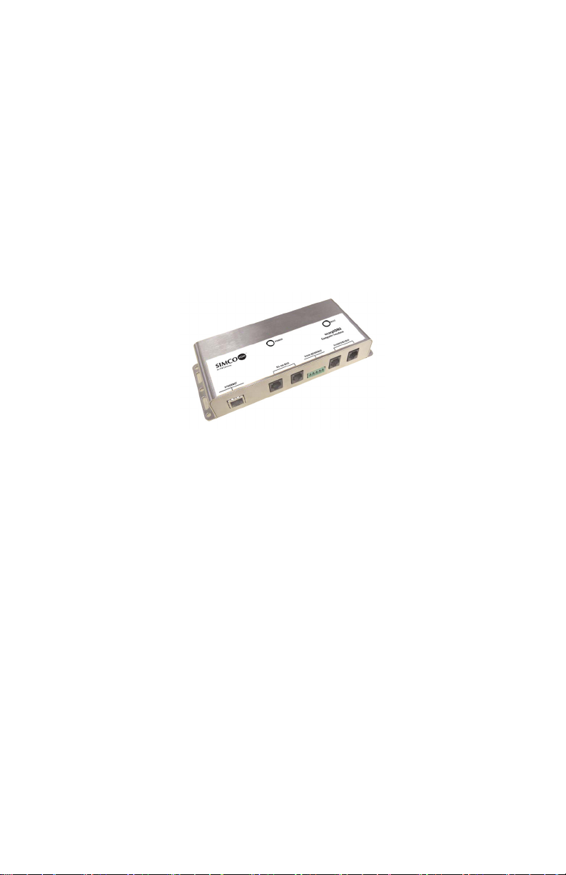
2.7 CI (Computer Interface)
The scorpION3 CI (Computer Interface) provides an interface
between the scorpION3 bar system and a personal computer or
local computer network via Ethernet connection. With Simco-Ion’s
monitor software, a user may set-up, monitor or control the
scorpION3 bar system from their computer. The computer interface
contains two RJ-11 connectors for direct connection to the
scorpION3 bar system, two RJ-11 connectors for connection to
other Computer Interfaces and an RJ-45 connector for connection
to a personal computer or local computer network.
The green LED Power indicator illuminates to indicate power and
flickers if an MMI is on the system chain transmitting commands.
The red LED Fault indicator illuminates if; the CI doesn’t detect bars
on the system chain, one of the bars on the system chain is
resetting, or if any of the bars on the system chain is in a fault
condition.
Where a computer interface is used on the system chain it is
necessary that any MMI on the system chain remain turned off
during power-up of the system chain. Once the system chain is
powered, then the MMI may be turned on to access the system. If
the MMI is connected to the system chain and turned on during
power-up of the system, communication with the computer interface
may be impaired.
scorpION3 5200969 Rev 4 21
Page 27

The computer interface normally draws power from the scorpION3
bar system via the RJ-11 connectors. However, the computer
interface may serve as the source of power for the bar system.
When using the computer interface to power the bar system, the
user must supply 24 VDC via the plug type terminal block labeled
user interface. Connect pin 1 to ground/return and pin 2 to +24 VDC.
NOTE: Users connecting to the scorpION3 in this fashion must
supply 200 mA per each bar connected plus 100 mA for the
computer interface and 50 mA for a hardwired MMI.
The user interface terminal block on the computer interface also
provides relay contact output for the fault alarm. Pin 4 is Common.
Pin 3 is Normally Closed. Pin 5 is Normally Open. The relay
contacts are rated for a maximum of 1 A at 30 VDC resistive with a
maximum switching voltage of 220 VDC.
The Computer Interface will automatically resolve bar address
conflicts (where more than one bar on a system chain has the same
address number). This feature is required to make the software
function properly. In the event of duplicate bar addresses on a
system chain, the CI will assign the next available address to the
“newest” bar on the chain. Bars that have been on the chain and
have established addresses will not have their addresses changed.
The process of testing and correcting duplicate bar addresses may
take several minutes, therefore when adding a bar to an existing
system that has a Computer Interface, allow the system to run for
approximately two minutes undisturbed.
scorpION3 5200969 Rev 4 22
Page 28

The personal computer software available with the Computer
Interface provides continuous monitoring of the bar system set-up
and operating parameters, the ability to adjust parameters and
display of diagnostic information. Detailed information on the
Computer Interface and software is available in publication
5200968, scorpION3 Monitor Software user manual.
scorpION3 5200969 Rev 4 23
Page 29

scorpION3 5200969 Rev 4 24
Page 30

3.1 Settings
3
Operation
scorpION3 5200969 Rev 4 25
Page 31

3.1 Settings
Measures of system performance vary according to environmental
factors including airflow velocity, air turbulence, presence of large
grounded objects, and the distance from the emitter to the
instrument.
Operating parameters can be adjusted to compensate for much of
the variation common to the workspace or mini-environment.
Increasing output current and/or lengthening the pulse time can
reduce discharge times but will also affect the relative level of space
charge and emitter life expectancy. Increasing overlap can reduce
space charge in pulsed mode. Balance adjustment should be made
after
setting output current, pulse time and overlap. Adjustments
must be saved using “save settings local to bar”.
Setup Recommendations
Factory default settings for the scorpION3 are for a typical tool or
mini environment installation with the scorpION3 bar installed under
the filter fan / top of the unit and a target distance of approximately
600 mm (24”).
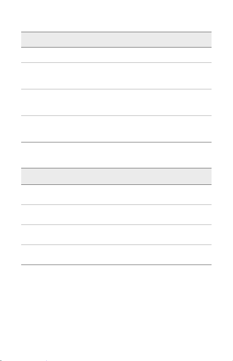
The following tables contain recommendations for starting setup
points and supply typical performance from the scorpION3 bar.
Actual performance will vary depending on your particular operating
conditions, bar length, airflow, temperature, humidity, obstructions,
and other environmental influences specific to your application.
scorpION3 5200969 Rev 4 26
Page 32
Approx.
Distance
300 mm
(12”)
450 mm
(18”)
600 mm
(24”)
750 mm
(30”)
Approx.
Distance
Offset
Volts
15 6SS- -30
10 10 SS - - 40
30 9 pulse 0.50 0 40
60 7 pulse 1.00 0 40
10 15 SS - - 50
30 12 pulse 0.75 30 50
60 10 pulse 1.25 30 50
10 18 SS - - 60
30 15 pulse 1.00 50 60
60 12 pulse 1.50 50 60
Discharge
Time (sec)
Bar
Mode
Pulse
Time (sec)
Pulse
Overlap %
Output
Level %
Table 2. Typical Setup Recommendations in 0.5 m/s (90 fpm) Airflow
Offset
Volts
Discharge
Time (sec)
Bar
Mode
Pulse
Time (sec)
Pulse
Overlap %
Output
Level %
300 mm
(12”)
450 mm
(18”)
600 mm
(24”)
750 mm
(30”)
±50 30 pulse 0.50 0 30
±100 15 pulse 1.00 0 30
±50 30 pulse 1.50 30 40
±100 20 pulse 1.75 30 40
±50 45 pulse 2.50 50 50
±100 30 pulse 3.00 50 50
±50 60 pulse 4.00 70 60
±100 40 pulse 5.00 60 60
Table 3. Typical Setup Recommendations: in still air (no airflow)
[Not recommended for use at less than 300 mm (12 inches) ]
Measures of performance should be made using the test methods
described in either your company methods and standard practice or
industry standard ANSI/ESD STM 3.1-2006 Ionization, Section 6.2
laminar flow hood ionization. A Charge Plate Monitor that meets the
requirements of ESD STM 3.1 should be used for this purpose.
scorpION3 5200969 Rev 4 27
Page 33

During normal operation, the Positive Ion and Negative Ion
indicators on the scorpION3 face label will glow green. If the bar is
in the steady state mode, the indicators will glow continuously. If the
bar is in the pulse mode, the indicators will flash alternately (with
both on during overlap), indicating ion output. If a fault occurs, the
indicator color will change to red. The indicators will typically briefly
flicker to show the receipt of IR commands from the MMI.
The scorpION3 bar with Air Assist provides reduced discharge
times according to the following table:
Operating Pressure
Typical Discharge Time
Reduction
Table 4. scorpION3 with Air Assist: Typical Discharge Time Reduction
50 kPa
(7.5 psi)
10% 30% 50% 60% 65%
100 kPa
(15 psi)
200 kPa
(30 psi)
300 kPa
(45 psi)
400 kPa
(60 psi)
The typical recommended operating pressure for the scorpION3
with Air Assist is 200 kPa (30 psi). Pressures less than 50 kPa (7.5
psi) may provide an air purge, but provide little overall reduction in
discharge times. Pressures greater than 300 kPa (45 psi) increase
air consumption without providing significant gains in discharge
time reduction. Compressed air or nitrogen must be clean, dry and
oil free.
scorpION3 5200969 Rev 4 28
Page 34

Maintenance
4.1 Cleaning & Calibration
4.2 Cleaning the Emitters
4.3 System Calibration
4.4 System Diagnostics
4
scorpION3 5200969 Rev 4 29
Page 35

4.1 Cleaning & Calibration
The scorpION3 bar is designed to require minimum maintenance,
cleaning, and calibration. There are no user serviceable parts within
the scorpION3 bar. No attempt should be made to disassemble or
repair defective products. Please contact Simco-Ion customer
service for information concerning repair or replacement.
Periodic cleaning of system emitters will make a valuable
contribution to optimum system performance and emitter life. All
corona ionization systems form deposits on the emitter tips over
time. The majority of these deposits are the result of the interaction
of moisture vapor with the electric field around the emitter. The
emitter material has little or no relationship to the formation of these
deposits. Your process and system performance demands must be
considered when determining a suitable interval for emitter
cleaning. Maintenance frequency also depends on the cleanliness
and relative humidity of the environment.
In most cleanroom environments, cleaning should be scheduled on
a quarterly basis. Simco-Ion recommends cleaning the system after
90 days. After initial cleaning, you may decide to adjust the cleaning
schedule. Emitter cleaning frequency is determined through
observation. Cleaning does not harm the emitters, and regular
cleaning of emitters removes deposits that can reduce emitter life
and affect system performance.
scorpION3 operation/calibration should be checked whenever the
emitters are cleaned.
scorpION3 5200969 Rev 4 30
Page 36
4.2 Cleaning the Emitters
Simco-Ion emitters have a serviceable life of three or more years in
a typical cleanroom environment when operated in conjunction with
a regular maintenance program. Evaluation of emitter condition
should be considered when cleaning the emitters. Worn emitter
replacement can be performed as part of a scheduled cleaning and
calibration.
Prior to any cleaning, power to the ionizer bar must be turned
off. This can be achieved using the MMI or by simply
disconnecting the bar.
Avant tout nettoyage, alimentation de la barre ionisante doit
être éteint. Ceci peut être réalisé en utilisant le MMI ou
simplement en débranchant le bar.
1. Visually inspect each emitter electrode for signs of deposited
material. Typical deposits appear as a white coating on the
pointed tip region.
2. Simco-Ion recommends using the ITW-TEXWIPE model
TX726, CrushTube swab for cleaning the emitter electrodes. A
substitute method consists of a cleanroom swab saturated with
a solution of de-ionized water and isopropyl alcohol. These
items may be obtained from local cleanroom product suppliers.
3. The TX726 CrushTube swab is shipped with a protective sleeve
covering the white foam swab end. Remove the protective
sleeve to expose the swab end. Discard the protective sleeve.
The CrushTube swab has an inner glass vial of alcohol inside
of a plastic tube. Crush the inner glass vial by squeezing the
plastic tube, then tilt the foam swab end down to allow the
alcohol to wet the swab. Carefully insert the wetted swab onto
the emitter point, slowly rotate the tube, and withdraw. Repeat
until all deposited material has been removed. Each CrushTube swab may be used to clean from 5 to 8 emitter tips,
depending on the amount of material on each tip. When the
scorpION3 5200969 Rev 4 31
Page 37

swab fails to remove the material, a new swab should be used.
Clean all the emitter electrode points.
4. The bar housing can be cleaned using a cleanroom wiper or soft
cloth as appropriate.
scorpION3 5200969 Rev 4 32
Page 38

5. Allow all alcohol to evaporate before applying power to the bar.
6. It is recommended practice to develop a regular cleaning
schedule that meets your requirements and operating conditions.
scorpION3 5200969 Rev 4 33
Page 39

4.3 System Calibration
System calibration is a complete analysis of performance and
includes any adjustments that may be necessary to restore the
system. This should be performed after maintenance and cleaning
of the emitters has been completed. Adjustment to output level
(first) and ion balance settings (second) should be made only after
the emitters have been cleaned, and after every emitter cleaning or
replacement. Adjustments must be saved using “save settings local
to bar” or they will be lost when power is removed from the bar.
Standard system tests include charge discharge time and offset
voltage. Test data should include temperature, humidity, and air
velocity. Tests of the system are made in accordance with ANSI/
ESD STM 3.1-2006 Ionization, Section 6.2 laminar flow hood
ionization. Contact Simco-Ion for information concerning test
instruments and services.
scorpION3 5200969 Rev 4 34
Page 40

4.4 System Diagnostics
System diagnostics are available through the Man Machine
Interface (MMI) and the Computer Interface (CI). Diagnostic
information available includes the operating parameters the bar has
been set to, the value the bar is operating at and if any fault status
exists (a fault status is typically when the operating value is
consistently unable to achieve set operating parameter).
The system diagnostics can be accessed through the MMI by wired
or IR communication with the scorpION3 bar. When the diagnostic
menus are entered, the MMI downloads settings and operating data
from the bar. This information is displayed in a series of menus on
the MMI. A further description of this information is available in the
MMI section of this instruction manual and in the appendix.
System diagnostics are also available through the Computer
Interface. The computer interface offers continuous monitoring of
the bar system and display of diagnostic information. This
information is available on various screens presented via the host
personal computer. A further description of this information is
available in the Computer Interface section of this instruction
manual and in the appendix.
scorpION3 5200969 Rev 4 35
Page 41

scorpION3 5200969 Rev 4 36
Page 42

Specifications
5.1 Specifications
5.2 Parts & Accessories
5
scorpION3 5200969 Rev 4 37
Page 43

5.1 Specifications
scorpION3 Bar
Input Votage 24 VDC, 200 mA (max per bar) provided through the RJ-11 modular jack
Discharge <10 sec (typ), 24” with 90 fpm unidirectional airflow
Balance <30V (typ), 24” with 90 fpm unidirectional airflow
Timing
Pulse Overlap 0-100%, adjustable in 0.25% increments
Connectors
LED Indicators
Address Control Each bar can be set to one of 10 unique addresses
Mode Control
Communications RS-485
Fault Interface
Emitters Points Replaceable Ultra-clean Silicon or Tungsten
Cleanliness
Operating Env. Temperature 15-35°C (59-95°F) recommended; relative humidity 20-65%
Ozone <0.020 ppm
EMI Below background level
Mounting
Enclosure Reinforced Polycarbonate
Dimensions
0.125-6 sec, adjustable in 0.025 sec increments; steady state operation is
also available
6-pin RJ-11 modular jacks provide both power and communications
interconnections
2 bicolor LEDs provide information on pos/neg high voltage power supplies
and feedback condition; green NORMAL; red FAULT
Independent or slave; independent bars can be set to steady state or a
pulse rate independent of the system; slave bars will follow the pulse timing
of the master bar
3.5 mm (1/8”) phone jack, opto-isolated transistor that can be set to
normally off or normally on, this transistor (NEC PS2502-1) is toggled
during a fault condition. Phone jack connections: Tip - positive (collector),
Sleeve - negative (emitter), Fault Interface Maximum Ratings: Vceo
(collector emitter voltage) 40 VDC max; Veco (emitter to collector voltage)
6 VDC max; IC (collector current) 50 mA max
ISO 14644-1 Class 1 (Ultra-clean Silicon), ISO 14644-1 Class 4 (Fed. Std.
209e Class 10) (Tungsten)
Stainless steel brackets, with universal adjustable mounting centers.
Clamping thumbscrew Integrated #8-32 mounting nut
457 mm (18”); 610 mm (24”); 914 mm (36”); 1118 mm (44”); 1626 mm (64”);
1880 mm (74”); 2134 mm (84”)
1
scorpION3 5200969 Rev 4 38
Page 44
Weight
Warranty Two year limited warranty
Certifications RoHS 2 Compliant
scorpION3 Bar with Air Assist
Air Inlet ¼” QC Tube Fitting
Input Pressure 200 kPa (30 psi) recommended nominal, 700 kPa (100 psi) max, CDA
Air Consumption
Noise Level
Warranty Two year limited warranty
Certifications RoHS 2 Compliant
scorpION AC Adapter
Input Voltage
Output Voltage
0.8 kg (1.8 lb); 1.0 kg (2.1 lb); 1.3 kg (2.8 lb); 1.5 kg (3.2 lb); 2.0 kg (4.3 lb);
2.2 kg (4.9 lb); 2.5 kg (5.5 lb)
5.1 Nm3/h @ 200 kPa (3 scfm @ 30 psi); 8.5 Nm3/h @ 400 kPa (5 scfm @
60 psi); 13.6 Nm3/h @ 700 kPa (8 scfm @ 100 psi)
76 dB @ 200 kPa (30 psi); 82 dB @ 400 kPa (60 psi); 88 dB @ 700 kPa
(100 psi) measured 600 mm (24”) from bar
Universal 100-240 VAC, 47-63 Hz line voltage input through 3 pin IEC320
receptacle
24 VDC, 18W, 0.75A; Adapter powers a system of up to three bars (any
length), with one communication module (CI), and one hardwired ManMachine Interface control (MMI); RJ-11 adapter and modular cable
included
Certifications RoHS 2 Compliant
scorpION3 MMI Module Remote
Output IR (infrared) and hardwired RS-485
Controls Up Arrow/Down Arrow, Left Arrow/Right Arrow, Enter
Power On/Off Slide Switch
Indicators
Power
Enclosure Impact resistant ABS
Dimensions 4.40H x 7.70W x 1.25D in. (110 x 196 x 32 mm)
Weight 0.75 lb (0.34 kg) with battery
scorpION3 5200969 Rev 4 39
LCD menu driven user interface green/red LEDs indicate transmit/receive/
fault status
Standard 9V battery (Type 1604, Alkaline) or 24 VDC, 50 mA from bar
system chain (RJ-11 modular connectors) CAUTION: Risk of explosion
if battery is replaced by an incorrect type. Dispose of used batteries
according to the manufacturer’s instructions.
Page 45

CI Module
Input Power
Bar Connection RJ-11 modular jack/modular wire (power & communication)
Network Interface Ethernet (RJ-45 modular connector)
LED Indicators Green POWER; red FAULT
Dimensions 84 x 211 x 34 mm (3.30 x 8.30 x 1.35 in.)
Enclosure Stainless Steel
Software Windows 2000, Windows XP, Windows 7
1. Tested in accordance with ANSI/ESD STM3.1-2006.
24 VDC, 100 mA from bar system chain (RJ-11 modular connectors) or
User Interface terminal block
scorpION3 5200969 Rev 4 40
Page 46

5.2 Parts & Accessories
Part Nos. Description
4015454 18" ScorpION3 Ionizing Bar, Seven (7) Ultraclean Silicon emitters
4015455 24" ScorpION3 Ionizing Bar, Seven (7) Ultraclean Silicon emitters
4015456 36" ScorpION3 Ionizing Bar, Eleven (11) Ultraclean Silicon emitters
4015457 44" ScorpION3 Ionizing Bar, Fifteen (15) Ultraclean Silicon emitters
4015458 64" ScorpION3 Ionizing Bar, Nineteen (19) Ultraclean Silicon emitters
4015459 74" ScorpION3 Ionizing Bar, Nineteen (19) Ultraclean Silicon emitters
4015460 84" ScorpION3 Ionizing Bar, Nineteen (19) Ultraclean Silicon emitters
4011546 18" ScorpION3 Ionizing Bar, Seven (7) Tungsten (W) emitters
4011547 24" ScorpION3 Ionizing Bar, Seven (7) Tungsten (W) emitters
4011548 36" ScorpION3 Ionizing Bar, Eleven (11) Tungsten (W) emitters
4011549 44" ScorpION3 Ionizing Bar, Fifteen (15) Tungsten (W) emitters
4011550 64" ScorpION3 Ionizing Bar, Nineteen (19) Tungsten (W) emitters
4011551 74" ScorpION3 Ionizing Bar, Nineteen (19) Tungsten (W) emitters
4011552 84" ScorpION3 Ionizing Bar, Nineteen (19) Tungsten (W) emitters
4015461 18" ScorpION3 Ionizing Bar w/Air Assist, Seven (7) Ultraclean Silicon emitters
4015462 24" ScorpION3 Ionizing Bar w/Air Assist, Seven (7) Ultraclean Silicon emitters
4015463 36" ScorpION3 Ionizing Bar w/Air Assist, Eleven (11) Ultraclean Silicon emitters
4015464 44" ScorpION3 Ionizing Bar w/Air Assist, Fifteen (15) Ultraclean Silicon emitters
4015465 64" ScorpION3 Ionizing Bar w/Air Assist, Nineteen (19) Ultraclean Silicon emitters
4015466 74" ScorpION3 Ionizing Bar w/Air Assist, Nineteen (19) Ultraclean Silicon emitters
4015467 84" ScorpION3 Ionizing Bar w/Air Assist, Nineteen (19) Ultraclean Silicon emitters
4011560 18" ScorpION3 Ionizing Bar w/Air Assist, Seven (7) Tungsten (W) emitters
4011561 24" ScorpION3 Ionizing Bar w/Air Assist, Seven (7) Tungsten (W) emitters
4011562 36" ScorpION3 Ionizing Bar w/Air Assist, Eleven (11) Tungsten (W) emitters
4011563 44" ScorpION3 Ionizing Bar w/Air Assist, Fifteen (15) Tungsten (W) emitters
4011564 64" ScorpION3 Ionizing Bar w/Air Assist, Nineteen (19) Tungsten (W) emitters
4011565 74" ScorpION3 Ionizing Bar w/Air Assist, Nineteen (19) Tungsten (W) emitters
4011566 84" ScorpION3 Ionizing Bar w/Air Assist, Nineteen (19) Tungsten (W) emitters
5051195 Modular Interconnect Cable, 152 mm (6”)
5051168 Modular Interconnect Cable, 406 mm (16”)
5051196 Modular Interconnect Cable, 610 mm (24”)
scorpION3 5200969 Rev 4 41
Page 47

5051183 Modular Interconnect Cable, 914 mm (36”)
5051331 Modular Interconnect Cable, 2.13m (84”)
5051197 Modular Interconnect Cable, 3.05m (120”)
5051328
5051329
5051330
4107405 Mounting Bracket with integrated 8-32 nut
4107878 Mounting Bracket with clearance hole for M4 or M5 (#8 or #10) screw
ScorpION2/3 AC Adapter, 24 VDC Out, 100-240VAC Universal Input with North
American (NEMA5-15P)/Japan Line Cord.
ScorpION2/3 AC Adapter, 24VDC Out, 100-240 VAC Universal Input with
European (CEE7) Line Cord.
ScorpION2/3 AC Adapter, 24 VDC Out, 100-240 VAC Universal Input with United
Kingdom (BS 1363) Line Cord
scorpION3 5200969 Rev 4 42
Page 48

6
Warranty & Service
Simco-Ion provides a limited warranty for the scorpION3 Ionizing
Bar. New products manufactured or sold by Simco-Ion are
guaranteed to be free from defects in material or workmanship for a
period of two (2) years from date of initial shipment. Simco-Ion
liability under its new product warranty is limited to servicing
(evaluating, repairing, or replacing) any unit returned to Simco-Ion
that has not been subjected to misuse, neglect, lack of routine
maintenance, repair, alteration, or accident. In no event shall
Simco-Ion be liable for collateral or consequential damages.
Consumable items such as, but not exclusive to, emitter points,
emitter wires, batteries, filters, fuses or light bulbs are only covered
under this warranty if found defective as received with the new
product.
To obtain service under this warranty, please contact Simco-Ion
Technical Support at [email protected] or (510) 217-
0470.
scorpION3 5200969 Rev 4 43
Page 49

scorpION3 5200969 Rev 4 44
Page 50

Appendix A
MMI Navigation
Reference Guide
START: Splash screens: Simco-Ion, software version, display test, indicator LED test.
WIRED MODE
*select mode (wired or address test)
*wired
*searching
*select bar, preset, or sysmon
*bar scroll list (LEDs on selected bar flash)
*bar change address
*select settings or diagnostics
WIRED SETTINGS NAVIGATION
power
output
pulse/steady state
slave/independent
pulse time
1
not present if in steady state
2
not present if slave
scorpION3 5200969 Rev 4 45
1, 2
overlap
balance
1
1
fault threshold
HV on/off w/fault
fault contact
*save local to bar
*save as preset
Page 51

DIAGNOSTIC NAVIGATION
feedback
fault status accumulators
bar information
*reset bar command
PRESET NAVIGATION
*select preset number (P01, P02,…P14)
power
output
pulse/steady state
slave/independent
pulse time
1
not present if in steady state
2
not present if slave
* Hot Keys are NOT enabled
UPLOAD PRESET NAVIGATION
*select bar
*enter=execute (transmit preset settings to bar)
1, 2
overlap
balance
1
1
fault threshold
HV on/off w/fault
fault contact
*save as preset
*upload to bar
SYSTEM MONITOR
*MMI screens rotation showing fault status code for each bar
(MMI LED’s indicate bar fault status).
IR MODE NAVIGATION
*select bar or preset
IR ACQUISITION (1st READBACK)
*Point MMI at bar & press enter
*accept bar address
*select settings or diagnostics
IR SETTINGS NAVIGATION
power
output
pulse/steady state
slave/independent
scorpION3 5200969 Rev 4 46
1
Page 52

pulse time
1
not present if in steady state
2
not present if slave
IR DIAGNOSTICS NAVIGATION
feedback
fault status accumulators
bar information / serial number
*reset bar command (point MMI & enter=execute)
ADDRESS TEST
*searching for address conflicts
*accept or change address conflicts
*change desired address
HOT KEYS
up & left jump to top of menu
up & right jump to save settings local to bar
down & right jump to fault status accumulators
down & left jump to feedback (program, current , drive monitors)
left & right jump to balance adjustment
1, 2
overlap
balance
1
fault threshold
HV on/off w/fault
fault contact
*save local to bar
*save as preset
* Hot Keys are NOT enabled
scorpION3 5200969 Rev 4 47
Page 53

Appendix B
Fault Status Code
Reference Guide
Fault
No.
0 No Faults N/A N/A
1
2
3
Message Possible Causes
Emitters need cleaning.
Positive Ion
Output Too Low
Negative Ion
Output Too Low
Ion Output Too
Low
Emitter housing or emitter
electrode not seated.
HV open circuit.
Pos HV supply is faulty.
Emitters need cleaning.
Emitter housing or emitter
electrode not seated.
HV open circuit.
Neg HV supply is faulty.
Unable to drive Ion Output
from either supply (as
currently set).
Emitters need cleaning.
Emitter housing or emitter
electrode not seated.
HV open circuit.
HV supplies faulty.
Potential Actions
(in order of occurrence)
Clean emitters.
Check emitter housing & emitter
electrode seating.
Reduce Ion Output setting.
Replace emitter electrodes.
Replace Pos HV supply.
Replace bar.
Clean emitters.
Check emitter housing & emitter
electrode seating.
Reduce Ion Output setting.
Replace emitter electrodes.
Replace Neg HV supply.
Replace bar.
Clean emitters.
Check emitter housing & emitter
electrode seating.
Reduce Ion Output setting.
Replace emitter electrodes.
Replace HV supplies.
Replace bar.
scorpION3 5200969 Rev 4 48
Page 54

Excessive drive levels.
Emitters need cleaning.
Ion Output Too
4
High
Positive Ion
5
Output Too High
Negative Ion
6
Output Too High
Program Voltage
7
Error
8 Pos Control Error I/O board fault.
9 Neg Control Error I/O board fault.
10 Internal Fault Hardware problem.
Pos Feedback
11
Error
Neg Feedback
12
Error
13 Feedback Error I/O Board fault.
14 Multiple Fault
Communication
15
Fault
Bar located near ground
plane or arcing.
HV short circuit.
NV supplies faulty.
Emitters need cleaning.
Bar located near ground
plane or arcing.
HV short circuit.
Emitters need cleaning.
Bar located near ground
plane or arcing.
HV short circuit.
I/O board fault.
I/O board fault.
Faulty Pos HV supply.
I/O board fault.
Faulty Neg HV supply.
Must be interpreted by a
Simco-Ion technician.
Fault in RJ-11 connectors
or modular cable.
Clean emitters.
Increase Ion Output setting.
Adjust Balance setting.
Adjust humidity or airflow.
Relocate bar or ground plane.
Replace bar.
Clean emitters.
Adjust Balance setting.
Increase Ion Output setting.
Adjust humidity or airflow.
Relocate bar or ground plane.
Replace bar.
Clean emitters.
Adjust Balance setting.
Increase Ion Output setting.
Adjust humidity or airflow.
Relocate bar or ground plane.
Replace bar.
Replace I/O board.
Replace bar.
Replace I/O board.
Replace bar.
Replace I/O board.
Replace bar.
Check op-amp on I/O board.
Replace I/O board.
Replace bar.
Replace I/O board.
Replace Pos HV supply.
Replace bar.
Replace I/O board.
Replace Neg HV supply.
Replace bar.
Replace I/O board.
Replace bar.
Replace bar.
Check connections and modular
cable.
scorpION3 5200969 Rev 4 49
Page 55

Notes
scorpION3 5200969 Rev 4 50
Page 56

scorpION3 5200969 Rev 4
Technology Group
1601 Harbor Bay Pkwy, Ste 150
Alameda, CA USA 94502
Tel: 510-217-0600
Fax: 510-217-0484
Toll free:
Sales services: 510-217-0460
Tech support: 510-217-0470
800-367-2452
www.simco-ion.com
 Loading...