

Page 1

Manual
Control Unit
1400002_EN/04.2017
GFCD 16
Page 2
Control Unit
SI MATE K A/ S
www.simatek.com
Hotline: +45 4046 7525
[email protected]
2
Doc. No.: 1400002_EN
-
Date: 04.2017
GFCD 16
Index
Main features 3
1.
2. Technical features 3
3. Installatio n guidelines 4
4. Preliminary checks 5
5. Electrical connections 5
6. Filter taps 5
7. Settings 6
8. Remote control 9
9. Shut down cleaning 9
10. Pre-coating function 9
11. ΔP/Operating valve button 10
12. Hour counter 10
13. Zero adjust 10
14. Remote transmission of the ΔP value (GFCD 16:4 and GFCD 16:12 only) 11
15. Display messages 12
16. Troubleshooting 12
17. Fuse table 12
18. Factory settings/Program menu 13
19. Legend 14
20. General assembly Simatek GFCD 16: 2-16 valves 15
21. Electric diagram for Simatek GFCD 16: 2-10 valves 16
22. Electric diagram for Simatek GFCD 16: 12-16 17
23. Declaration of Conformity 18
NOTE: Figures shown inside square brackets […] refer to positions on page 15.
ATTENTION: Before use, read the instructions thoroughly to acquire sufficient knowledge of the product. For your
convenience, keep this sheet as a quick reference.
Subject to change without notice.
The GFCD 16 unit is to be installed by trained personnel only!
Rev.:
Page 3
Control Unit
SI MATE K A/ S
www.simatek.com
Hotline: +45 4046 7525
[email protected]
3
Doc. No.: 1400002_EN
-
Date: 04.2017
Enclosure
Grey ABS – transparent cover (option: 2 screws for transparent cover).
Grade of protection
IP65.
Dimensions
Simatek GFCD 16: 4 / 8 / 12 / 16 outputs: case 213 x 185 x 113 mm.
Weight
Simatek GFCD 16: approx. 2 kg.
Connections
Push in terminal blocks – with max. wire section of 2.5 mm².
Temperature
Storage: -20°C/+80°C.
Operating: -10°C/+50°C, with duty cycle 30%.
Voltage available
Input: 230 V (±10%) – 50 /60 H z / Output: 115/230/24V AC, 24 V DC.
Special version 24V DC/24V DC
Power consumption
Without output 2.5 VA
Output: 25 VA / AC or 20 W / DC
Relay
2 A – 250 V AC
Pulse time
0.01 – 9.99 sec.
Pause time
1 – 999 sec.
Pause time in automatic
1-999 sec.
Max duty cycle
30%
Operating ΔP
0.01–3.00 kPa
Max pressure
75 kPa
Set ΔP alarm
0.01-3.00 kPa
ΔP pre-coating
0.01–3.00 kPa
Hour counter
0-65,999 hours
Remote control
Activated via external contact (norma lly open) fr e e of power.
Shut down cleaning
1 – 99 cycles. To be operated from the normally closed contact of fan remote
control switch.
Fuse
500 mA delayed 115 V-230 V. 2 A delayed 24 V-48 V.
GFCD 16
1. Main features
The Simatek GFCD 16 has been designed to guarantee the control of diaphr agm valv es mounte d on the puls e jet dust
collector filters containing filter bags or cartridges.
The main features of the Simatek GFCD 16 are:
⋅ Operates in MANUAL or AUTOMATIC mode.
⋅ Automatic start-up of cleaning cycle accor ding to set ΔP.
⋅ SHUT DOWN CLEANING with selectable number of cleaning cycle s .
⋅ PRECOATING function for new filters or filte r s equip p ed with new filte ring elements.
⋅ REMOTE function.
⋅ ALARM contact enabling connection to exter nal al arms.
⋅ ΔP value playback (option).
2. Technical features
Input: 115 V (±10%) – 50 /60 H z / Out p u t: 115/24V AC, 24 V DC.
See page 6, 7.1
The device should be disposed of in accordance with current European
regulations
The neutral of the power supply shall be connected to earth.
If this is not the case an isolation transformer is to be
installed and the neutral of the output to be earthed.
Otherwise the filter control will be damage d .
Rev.:
Page 4

Control Unit
SI MATE K A/ S
www.simatek.com
Hotline: +45 4046 7525
[email protected]
4
Doc. No.: 1400002_EN
-
Date: 04.2017
GFCD 16
3. Installation guidelines
• Do not expose the control unit to direct sunlight in orde r to preve nt over he a ting of the circuit b o ard.
• Connect the control unit to a continually power ed line to allow S HUT DOW N CLEANING when the fan s top s and
to have maximum precision in the ΔP measurements.
• Protect the control unit from rain, water infiltration and humidity. Incomplete closing of the cover may cause
infiltration which can seriously d amage the circui t b o ard.
• Do not have cables entering via the upper part of the Control unit box.
• Do not install any electronic devices on vibrating structures.
• Use only cable glands with protection grade IP65 and of prop er size (ac co rd ing to the cable us ed).
• A disconnecting switch has to be installed on the power line befo re the co ntro l unit.
• Do not attempt to repair the control unit – contact Sim atek!
• All wiring has to be carried out by a qualified electri c ian to prevent any r isk of f ire and electri c al s hocks.
• The control unit wiring has to be performed in in such a way that the different typ es of cables (po wer, relay’s
contact, valve output, 4-20 mA output) are kept separated and no t pass ing cl ose by the PCB.
• Before opening the unit make sure that the control unit is switched off (switc h o n/off [1] on 0 and wires on
clamps [4] disconnected, including conne c tion to alarm/signal relays.
• All the control unit electrical connec tions, including solenoid valves, have to use separate paths in respect to the
other loads.
• Voltage selector’s jumpers have to be positio ne d only by skilled personnel and following the instructions.
• A wrong voltage selector s jumpe rs po s itioning may cause potential danger to the personnel safety.
Rev.:
Page 5

Control Unit
SI MATE K A/ S
www.simatek.com
Hotline: +45 4046 7525
[email protected]
5
Doc. No.: 1400002_EN
-
Date: 04.2017
GFCD 16
4. Preliminary checks
1. Check that the S ima tek GFCD 16 ha s no power (sw itc h on/o ff [1] o n 0 and terminals [4] disc o nne c ted ).
2. Check that the s upply vo ltag e, ind ic ate d on the yellow label [22] as “IN” corresponds to the available power
supply (Voltage and Frequency).
3. Check that the s upply vo ltag e to valv es, ind i c ate d o n the yellow lab e l [22] as “OUT” corr esp onds to the
voltage/frequency as indicated on the coi ls .
5. Electrical connections
1. Check that the S ima tek GFCD 16 does not have power (s witch on/off [1] on 0 and terminals [4] disconnected).
2. Unscrew and remove the terminals cover [20].
3. Extrac t the removable terminals [2].
4. Make sure that the suppl y voltage to valves indicated on the yellow label [22] as “OUT” corresponds to the
voltage/frequency as indicated on the coi ls .
5. Connec t the valve s to the terminal blocks [2], between terminal C and the numbered outputs.
6. Earthing [3 ] of the valves is necessary when the output voltage is ≥ 48V.
7. NEVER connect the Common or valve output to earth [3].
8. The Commons are inte rconnected on the printed circuitry.
9. The outputs are “s tatic ” type , with “ ze ro -crossing” command, to prevent electrical disturbances.
10. Check that the valve connections are correct and isolate d in regard to earthing, by measuring the isolation
between ground [3] and Common with outputs terminal.
11. Put the extractable terminals back in place
12. Replace the terminals cover [20] and tighten the screws .
6. Filter taps
It is very important that dust and liquid are not allowed to enter into the hose co up lings, as this will damage the
instrument. Any dust clogging in the hose connec tions may also result in indication errors, so protection by a filter
element is recommended.
For documentation regarding these DP f ilte rs , p le ase see documenta tio n for the DP filter.
Rev.:
Page 6
Control Unit
SI MATE K A/ S
www.simatek.com
Hotline: +45 4046 7525
[email protected]
6
Doc. No.: 1400002_EN
-
Date: 04.2017
GFCD 16
7. Settings
7.1 Voltage selecti on
CHECK:
1. That the Simatek GFCD 16 is not powered (switc h on/off [1] on 0 and terminals [4] disconnected).
2. That the supp ly volta g e , indicated on the ye llo w lab e l [22] as “IN” corresponds to the available supply voltage.
3. That the supp ly volta g e to valve s , ind ic a ted on the yell ow labe l [22 ] as “OUT ” corr e sponds to the
voltage/frequency as indicated on the coi ls .
IF THESE 3 CONDITIONS ARE MET, GO TO PARAGRAPH 7.2.
OTHERWISE, CAREFULLY FOLLOW THE P ROCEDURE BELOW!
A. Supply voltage selection
1. Unscrew the two 2 screw s [21] (optional), and open the Simatek GFCD 16 transparent cover.
2. Remove the 4 screws of the front panel. Lift the front panel (do not remove it, as it is connected to the base of
the enclosure!).
3. Check that the s upply vo ltag e, se le c ta b le by jumper [5], cor responds to the one available from the supply
voltage (e.g. both are set to 230 V).
4. Should the two volta g e s be diffe rent, m ov e the jum per [5 ] in order to selec t the same supp ly volta g e .
5. Go to point 7.1B.
B. Selection of power supply to the valves
1. Check that the s upply vo ltag e to the valve s , sele c tab l e by jumpe rs [6] and [6A], corresponds to the supply
voltage indicated on the coils of the valves (e.g . both 230 V).
Jumper [6]: 1HV = 110 V; 2HV = 220 V; LV = 24 V
Jumper [6A]: HV = 110 / 220 V; LV = 24 V
2. Should the two voltages be different, move the jumpers [6] and [6A] in order to select the same supply voltage
as indicated on the coils.
Jumper [6]: 1H V = 110 V; 2HV = 220 V; LV=24V
Jumper [6A]: HV = 110 / 220 V; LV = 24V
3. Go to section 7.1C .
C. Selection of power supply frequency to the valves (AC/DC)
1. Make sure that the output frequency to the valves selectable by jumper [8] corresponds to the value indicated
2. Should the two fr eque nc ie s be differe nt, m ov e the jumper [8] in orde r to se lect the s ame freq uency as
3. Put the front p anel ba ck in place and fasten the 4 screws.
4. Close the tr ansp are nt cover by means of the two screws [21] (optional).
CAUTION! B o th jump ers [6 ] and [6A] mus t corre s pond to the sam e voltag e !
on the coils (e.g. both are set to AC).
indicated on the coils.
Never select 115 or 230 V DC for output!
Rev.:
Page 7

Control Unit
SI MATE K A/ S
www.simatek.com
Hotline: +45 4046 7525
[email protected]
7
Doc. No.: 1400002_EN
-
Date: 04.2017
1) Press SELECT MENU [9]:
The no. 1 will flash on the display [7]:
2) Press SELECT MENU [9]:
The no. 2 will flash on the display [7]:
3) Press SELECT MENU [9]:
The no. 3 will flash on the display [7]:
4) Press SELECT MENU [9]:
The no. 4 will flas h on the display [7]:
5) Press SELECT MENU [9]:
The no. 5 will flas h on the display [7]:
The no. 6 will flash on the display [7]:
7) Press SELECT MENU [9]:
The no. 7 will flash on the display [7]:
8) Press SELECT MENU [9]:
The no. 8 will flash on the display [7]:
9) Press SELECT MENU [9]:
The no. 9 will flash on the display [7]:
Both in Automatic and Manual mode the cleaning of the filter will start only
GFCD 16
7.2 Parameters selection
Connecting the power supply [4]:
L = phase, N = neutral
On/off switch [1] on 1. The display [7] will indicate fo r a few seconds the release code of Simatek GFCD 16. Once the
code disappears the display [7] will show the letter P fo llowed by the ΔP value of the filter.
LED OK [18] is on:
LED Auto [16] if Simatek GFCD 16 is in automatic mode
or LED Pause [12] if Simatek GFCD 16 is in manual mode
ATTENTION! The display [7] must show a ΔP value of “0” kPa when the fan is switche d off. O therwise adjust the zero
ΔP as indicated in paragraph 13, page 9.
Using keys “+/–” [10] select Manual or Automatic mode. (0 = Manual, 1 =
Automatic).
Using keys “+/–” [10] select the No. of valves you wish to connect (example:
if you wish to connect 4 valves to Simatek GFCD 16, select 4). When skipping
this step of the menu the Simatek GFCD 16 will automatically se t the No. of
valves as if they were all connected (if your model is Simatek GFCD 16: 4),
then 4 valves will be recognized, (if your model is Simatek GFCD 16: 12),
then 12 valves will be recognized.
6) Press SELECT MENU [9]:
Using keys “+/–” [10] select Pulse Time.
(0.01-9.99s).
Using keys “+/–" [10] select Pause Time in Manual mode. (1-999 sec).
Caution: if you have selected Automatic in step 1) of the menu you have to
select Pause Time in Shut down cleaning.
Using keys “+/–” [10] select Pause Time in Automatic mode.
(1-999s).
Caution: skip this step if you have selected Manual in s te p 1).
Using keys “+/–” [10] select operating ΔP.
(0.01–3.00 kPa).
Each time the ΔP of the filter exceeds the Operating ΔP, filter cleaning w i ll
begin. As soon as ΔP of the filter goes below the Operating ΔP, filter cleaning
will be interrupted (with differential of – 0.05 kPa).
Using keys “+/–” [10] select Set Delta -P Alarm.
(0.01-3.00 kPa).
If the Delta-P Alarm value is reached in the filte r , S im atek GFCD 16 giv es an
alarm. Display shows “PP1”. It is possible to have signalling if you connect
relay’s terminals C and NC [24].
Using keys “+/–” [10] select No of cycles of Shut down cleaning.
(0-99).
(Select 0 if you do not wish to have Shut down cleaning).
Shut down cleaning starts automatically w he n the ΔP of the filter goes b e low
0.10 kPa and Fan contact is open.
Caution: Shut down cleaning will start onl y when MPS is work ing in auto matic
mode
Using keys “+/–” [10] select ΔP Pre-coating.
(0.01–3.00 kPa).
Rev.:
Page 8

Control Unit
SI MATE K A/ S
www.simatek.com
Hotline: +45 4046 7525
[email protected]
8
Doc. No.: 1400002_EN
-
Date: 04.2017
when ΔP will exceed ΔP Pre-coating, regardless of the value of Operating ΔP.
10) Press SELECT MENU [9]:
On the left- hand side of the display [7] appears the letter C followed by a
11) Press SELECT MENU [9]:
On the left-hand side of the display [7] appears the letter F followed by three
12) Press SELECT MENU [9]:
On the display [7] flashes the letter L together with the thr ee final numbers
13) Press SELECT MENU [9]:
On the display [7] flashes the letter H together with the two initial numbers
14) Press SELECT MENU [9]:
On the display [7] appears the letters oooo (zero ΔP Automatic).
the next valve.
GFCD 16
This is to allow the filter elements to form a dust cake in their s urf a ce.
- Select “0” if you do not wish to use Pre-coating.
- Once ΔP Pr e-coating is reached and exceeded, this function will
automatically be excluded and the cleani ng cycle will b e per fo rmed according
to the Operating ΔP. Ple ase dig it a new value of ΔP Pre-co ating if yo u wish to
reactivate the function.
- Shut down cleaning may start only w hen ΔP Pre-coating has been previously
reached, otherwise Shut down cleaning will not s tart even if the fan is
switched off.
three digit number. Using keys “+/–” [10] to perform the 4 mA tuning.
Adjust the numeric value till you can read the correct ind ic ation o f 4 mA on an
external instrument.
digit number. Using keys “+/–” [10] to perform the 20 mA tuning.
Adjust the numeric value till you can read the correct ind ic ation o f 20 mA on
an external instrument.
(from 0 to 999) out of 5 indicating the total number of operating hours for the
Simatek GFCD 16. (Example: if the control unit works for 12,27 0 ho urs the
display will show L 270).
(from 0 to 65) out of 5 indicating the total number of operating hours for the
Simatek GFCD 16. (Example: if the control unit works for 12,27 0 ho urs the
display will show H 12).
Press the keys “+” [10] so that the first digit flashes : P or – followed by
three digits. Press SELECT MENU [9] to start the calibration.
Note: Remove the pipes before operating.
LED Pulse [11] will indicate that a valve is activated.
LED Pause [12] will indicate that the Simatek GFCD 16 is waiting to ac tivate
Rev.:
Page 9

Control Unit
SI MATE K A/ S
www.simatek.com
Hotline: +45 4046 7525
[email protected]
9
Doc. No.: 1400002_EN
-
Date: 04.2017
NOTE!
⋅ Valves are pulsed from outlet No. 1 onwards.
GFCD 16
⋅ Check that during the first cleaning cycle ev ery v alve is activated.
⋅ If manual mode is used we suggest setting the Simatek GFCD 16 working p aram e ters to
clean the filter at the lowest possible frequenc y , ther eby reducing the little dust escape
arising during jet-pulsing, achieving a longer lifetime of filter bags/cartridges and reducing
the compressed air consumption.
⋅ Pause time should allow an efficient filter c le a ning in the worst co nditio ns , but should never
be shorter than the time needed to re-pressurise the compressed-air tank!
⋅ While selecting parameters (in Sele c t menu), S imate k GF CD 16 w ill return to normal
operation if no buttons are pressed within a 5 minute inter val.
8. Remote control
ATTENTION!
Simatek fits the Simatek GFCD 16 unit with a connectio n on termina ls Remote and Commo n [26].
If you wish to operate Simatek GFCD 16 with a remote switch, read the instruc tions below. If you do not wish to take
advantage of this opportunity, do not remove the conne c tion.
To activate Remote:
1. Unscrew a nd remov e the terminals c o ve r [20].
2. Remove the connection from terminals Remote and Common [26].
3. Bring an exter nal no-load and normally open (NO) contact to Remote and Common terminals [26].
4. Replace and s crew the terminals cover [20] tight.
5. Close the contac ts on the Remo te and Com mon termina ls [26 ] in order to enable the Remo te functi o n.
6. Should yo u open the contact on Remote and Common ter minals [2 6] the Simatek GFCD 16 will stop working.
Close the contact in order to start the cleaning cycle again from the position where it stopped.
9. Shut down cleaning
We suggest operating one or more cycles of Shut down cleaning at the end of each working session in order to remove
the residual dust of the filter. Shut down cle aning is s tarte d each time the ΔP of the filter goes below 0.10 kPa.
A free contact of the fan can be connecte d betw e e n clamp s F and C. The contact has to be close d w he n the fan is on.
In this case Shut down cleaning will not start until the fan is switched off .
The Shut down cleaning will start any time the ΔP goes below the value of 0.10 kPa and the contact is open.
ATTENTION!
Shut down cleaning will only start if Simatek GFCD 16 is in Automatic mode!
Shut down cleaning will only start if ΔP Pre-coating has already been exceeded, otherwise Shut down cleaning will not
start even if the fan is switched off.
In order to activate Shut down cleaning:
Check that the Simatek GFCD 16 is in AUTOMATIC mode.
Select the NUMBER OF CYCLES of Shut down cleaning (see 7.2 ).
(Select 0 to exclude Shut down cleaning).
Shut down cleaning starts when the ΔP goes below 0.10 kPa, and the fan contact (betw een F and C) is ope n. LED Shut
down [33] will then flash. Shut down cleaning will start from the next valve and will consider the existing cycle as the
first cycle.
Once Shut down cleaning is completed LED Shut down [33] will remain o n.
10. Pre-coating function
Pre-coating delays the beginning of the filter c le aning c ycle in ord er to allo w the filte r elements to form a thin dust
cake on their surface.
ATTENTION!
If you select ΔP Pre-coating, cleaning will start only after having reached set ΔP Pre-coating both in Automatic and
Manual mode disregarding the Operating ΔP value.
Rev.:
Page 10

Control Unit
SI MATE K A/ S
www.simatek.com
Hotline: +45 4046 7525
[email protected]
10
Doc. No.: 1400002_EN
-
Date: 04.2017
GFCD 16
To activate Pre-coating:
Select ΔP Pre-coating as per instruc tio ns in paragraph 7.2. LED Pre-coating will flash.
If you do not wish to use Pre-coating, select 0 at step 9 of paragraph 7.2.
Selecting ΔP Pr e-coating must be between 0 and 3.00 kPa.
When ΔP in the filter reaches the ΔP Pre-coating value, the cleaning cycle is initiate d and the Pre-coating function is
simultaneously excluded. L ED Pre-coating [5] switches off.
If you wish to reactivate this function, selec t a new value of ΔP Pre-coating.
Shut down cleaning starts only if ΔP Pr e-coating has been exceeded, otherwise it will not start even if the fan is
switched off.
11. ΔP/Operating valve button
The letter P followed by 3 numbers appear on the display [7] when the control unit s hows the ΔP value of the filter.
Press the key Delta-P/valves [14] to read the number of the valve that will be activated and vice versa. The control
unit shows the letter E followed by the number of the valve that is ready to be activ ate d. Each time the control unit is
switched on the display [7] automatically show s the ΔP value in the filter (e.g. if Delta-P value is 0.2 kPa, the display
shows P0.20).
12. Hour counter
The Hour counter counts the number of hours that the Simatek GFCD 16 has been working . Counting starts each time
the ΔP of the filter exceeds 0.10 kPa.
How to read the Hour counter on the display [7]:
Press SELECT MENU [9] until the display [7] shows the letter L follo w ed by the las t 3 numbers (fr om 0 to 999) out of
5 indicating the total number of operating hours of the Simatek GFCD 16 (e .g. if the Simatek GFCD 16 has been
working for 12,270 hours the display will show L270 .
Press SELECT MENU [9] until the display [7] shows H followed by the first 2 digits (from 0 to 65) indica ting the total
number of hours that the Simatek GFCD 16 has been working. (Examp le : if Simate k GFCD 16 has been work ing fo r
12,270 hours, the display will show H12 ) .
13. Zero adjust
Disconnect the pressure tubes, if the disp lay [7] doe s not show 0.00 kPa procee d as follo ws:
Press SELECT MENU [9]: the letters oooo (zero ΔP Automatic) will ap pe ar o n the displa y [7 ].
Press the “+”key [10], so that the first digit will flash: P or – followed by three digits.
Press SELECT MENU [9] to start the calibration.
NOTE! Remove the pipes before operating.
ATTENTION! This step must be oper ated only afte r minim um 30 minute s w arm up.
Rev.:
Page 11
Control Unit
SI MATE K A/ S
www.simatek.com
Hotline: +45 4046 7525
[email protected]
11
Doc. No.: 1400002_EN
-
Date: 04.2017
GFCD 16
14. Remote transmission of the ΔP value (GFCD 16:4 and GFCD 16:12 only)
It is possible to transmit the ΔP that is shown on the display of the Simatek GFCD 16 onto anothe r ins tr um e nt by
means of the 4-20 mA board [29].
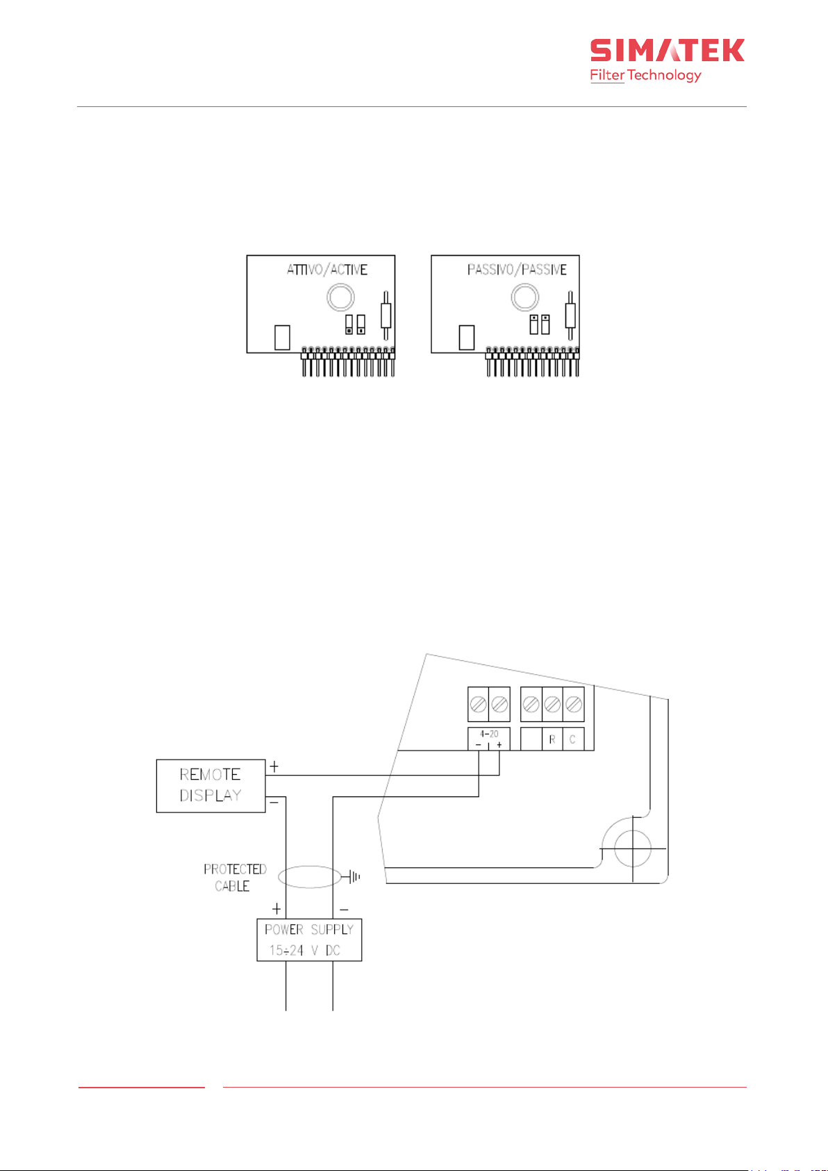
The output signal can be of “active” or “passive” type – please refer to the drawing below explaining how to choose the
type of signal (Active is selected as default at the facto ry ).
14.1 4-20 mA ac t ive output
No need for an external power supply, connect the external ins truments to the terminals [28].
14.2 4-20 mA passive output
ATTENTION! In this case the 4-20 mA outlet is passive. It needs to be connected to an external power source!
1. Connec t the positive (+) terminal of the remote unit to the 4-20 mA POS terminal [28].
2. Connec t the (-) term inal of a Stable powe r sour ce (15 -24 V DC) to the 4-20 mA NEG terminal [28].
3. Connec t the positive terminal of power supply to the negative terminal of the external instrument.
4. Use a shielded cab le to co nnect it.
Rev.:
Page 12
Control Unit
SI MATE K A/ S
www.simatek.com
Hotline: +45 4046 7525
[email protected]
12
Doc. No.: 1400002_EN
-
Date: 04.2017
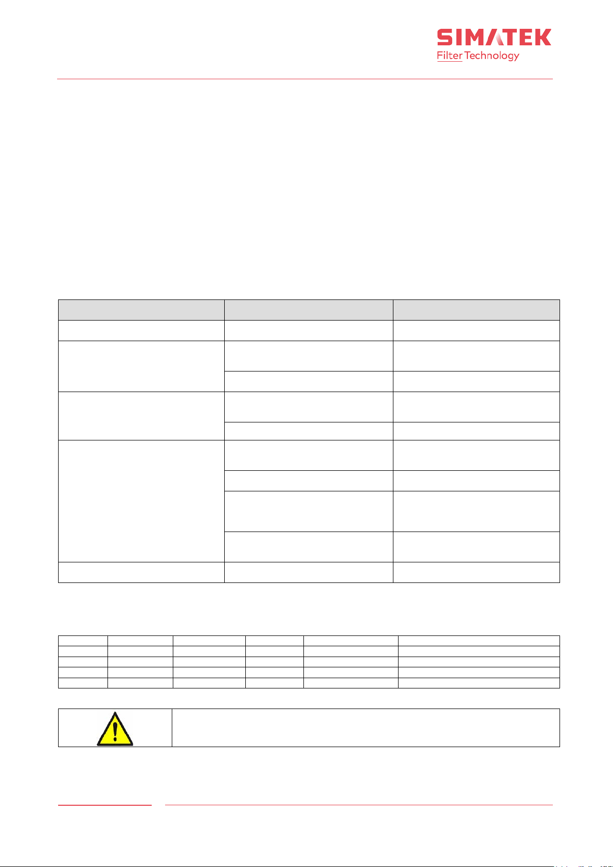
Problem
Probable cause
Solution
Display is blank and all LEDs are off
No power supply
Check the electrical terminals [4]
Display Shows Sb
The connection on terminals Remote
Check the connection
Check fuse F1 [31]
Replace the fuse (see chapter 17)
Some valves are ignored
Wrong electrical connections betwe e n
Check connections [2]
Coils are interrupted
Check coils continuity
Display shows the pulsing sequence
The secondary of the transformer is
Contact Simatek
Power circuit is damaged
Contact Simatek
Supply voltage to the valves is
Check or re-select supply voltage
Wrong connection between Simatek
Check connections [2]
LED OK [18] is off
Microprocessor failure
Contact Simatek
Name
Size
Value
Type
No. on drawing
Description
F3
5 x 20
500 mA
T
[23]
115/230 V main supply fuse
F3
5 x 20
2 A T [23]
24/48 V main supply fuse
F1
5 x 20
1.6 A
T
[31]
Output 24 V and Rem-Fan
F2
5 x 20
630 mA
T
[32]
+ 5 V internal power supply
GFCD 16
15. Display messages
PP1: The control unit indicates that Alarm ΔP has been exceeded.
Stabilize the filter ΔP, press the key “-” [10] to reset the unit.
PPP: The maximum value of ΔP in the Simatek GFCD 16 has been exceeded (3.00 kPa).
Stabilize the filter ΔP, press key “-” [10] to reset the unit.
P---: ΔP value is <0.50 kPa.
In this case check that the filtered taps are correctly connected to the pressure ports of the Simatek GFCD 16
as described in paragraph 6.2.
if the problem continues:
Disconnect the tubes between the filtered taps and pre s s ure por ts .
Adjust the DP indication to 0 kPa as indicated on page 11, paragraph 13.
Connect the tubes between the filtered taps and pres s ure ports .
SB: the Remote contact is open [26].
16. Troubleshooting
but valves are not functioning
17. Fuse table
and Common [26] is not connected
Simatek GFCD 16 and coils
interrupted
different from voltages indicated on
the coils
GFCD 16 and valves
(See paragra p h 7.1)
In case of replacement you must respect the above value.
Rev.:
Page 13
Control Unit
SI MATE K A/ S
www.simatek.com
Hotline: +45 4046 7525
[email protected]
13
Doc. No.: 1400002_EN
-
Date: 04.2017
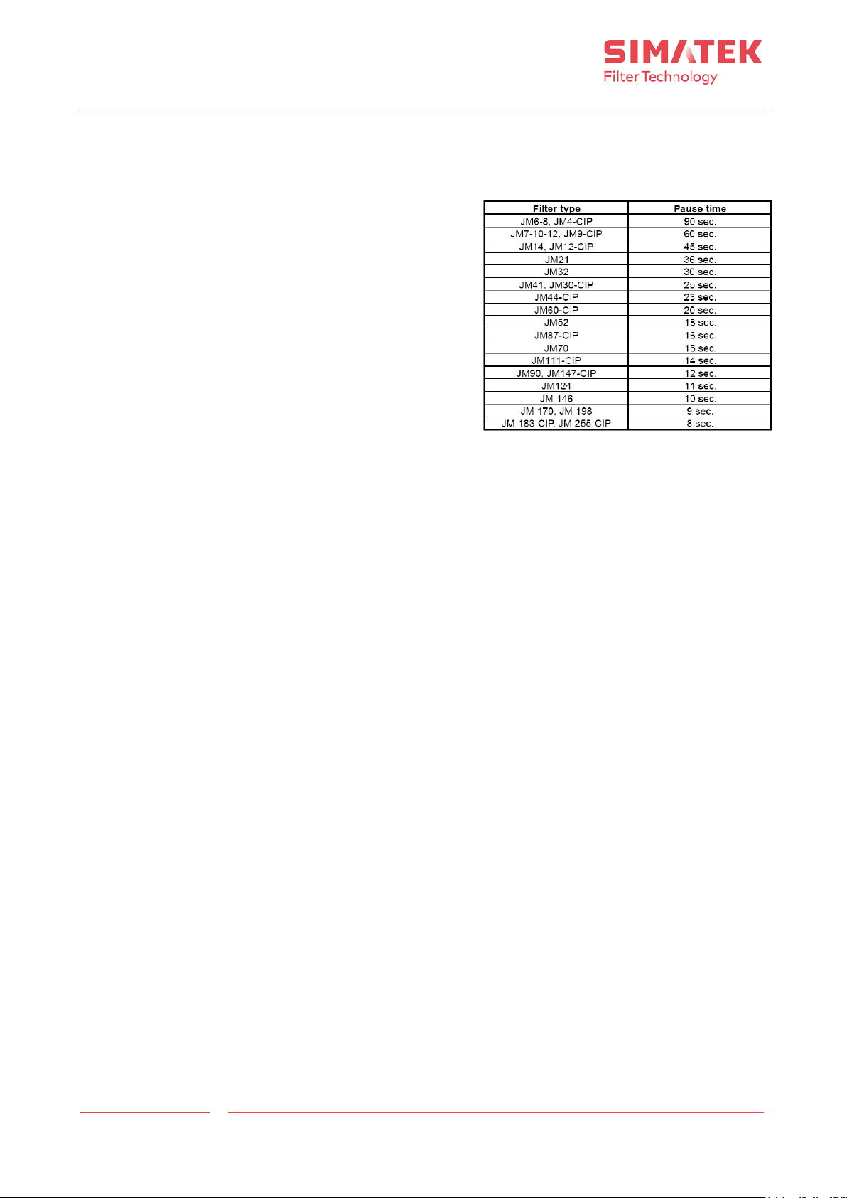
Recommended pause times for SimPact® 4T/4T-R
GFCD 16
18. Factory settings/Program menu
18.1 Pulse time
Simatek recommends a pulse tim e of 0.2 sec.
18.2 Pause time – Continuous
By continuous cleaning, the pause time is calc ulate d fr o m a
total cleaning time for the filter of 180 sec.
See recommended pause time by continuous cleaning for the
current filter type.
18.3 ΔP Start/stop
Each time the differential pressure in the f ilte r exc eed s the set
Value, bag cleaning starts. Bag cleaning stops, when the ΔP
drops below the set value.
ΔP Start/stop is set in Kilopascal (1 kPa = 100 mm WG).
18.4 Pause time – ΔP-Cleaning
By ΔP-Cleaning, the pause time should be set to a very low
value, as the control itself regulates how often the filte r is
cleaned.
However, the pause time must correspond to the compressor
capacity to ensure that the compressed air is admitted at f ull
pressure during the whole cleaning seq ue nce.
See Simatek’s filter manual regard ing com pr e sse d -air consumption.
18.5 Pause time – Shutdown cl eani ng
The pause time during shutdown cleaning may be set as requir e d acco rd ing to the prope rtie s of the dus t in ques tion,
however, the pause time must be correspond to the compressor capacity.
18.6 Shut down cycles
Bag cleaning will continue during the se t number of cyc le s (firs t valv e to last valv e ) afte r the ΔP in the filter has
dropped below 0.10 kPa (the fan is off).
Any equipment for removal of the separated dust should run during shut down cleaning.
Simatek recommends 2-3 cycles, a s the current cycle is regarded as the first shut down cycle. Therefore the first cycle
will not necessarily be a full cycle.
Shut down cleaning only works during ΔP-cleaning. If the ΔP in the filter exceeds 0.10 kPa during shut down cleaning,
the function will be interrupted, and ord ina ry bag cle aning will s tart.
18.7 ΔP Alarm
Each time the differential pressure in the filte r exc eed s the set value , an alarm is g iven. If required, the signal may be
led to e.g. a control room.
ΔP Alarm is set in kPa.
filters
Rev.:
Page 14

Control Unit
SI MATE K A/ S
www.simatek.com
Hotline: +45 4046 7525
[email protected]
14
Doc. No.: 1400002_EN
-
Date: 04.2017
GFCD 16
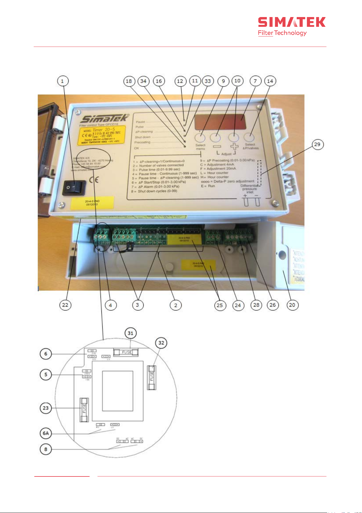
19. Legend
[1] On/off switch
[2] Push in valves terminals
[3] Valves earthing
[4] Power supply terminals
[5] Jumper for inlet supply voltage selection
[6] Jumper for voltage selection to valves
[6A] Jumper for voltage selection to valves
[7] Display
[8] Jumper for the frequency selection to valves (AC/DC )
[9] Push button Select Menu
[10] Push buttons +/[11] LED Pulse
[12] LED Pause
[14] Push button Delta P/valves
[16] LED ΔP Cleaning
[18] LED OK
[20] Terminals cover
[21] Transparent cover fixing screws (op tio na l)
[22] Yellow label indicating IN/OUT voltage frequency
[23] Main fuse
[24] Relay terminals
[25] Product code and serial number
[26] Remote terminal
[28] Output clamps for 4-20 mA signal
[29] Optional 4-20 mA board
[31] Output fuse 24 V and Fan – Rem
[32] + 5 V internal power supply fuse
[33] LED Shut down
[34] LED Pre-coating
Rev.:
Page 15
Control Unit
SI MATE K A/ S
www.simatek.com
Hotline: +45 4046 7525
[email protected]
15
Doc. No.: 1400002_EN
-
Date: 04.2017
GFCD 16
20. General assembly Simatek GFCD 16: 2-16 valves
Rev.:
Page 16
Control Unit
SI MATE K A/ S
www.simatek.com
Hotline: +45 4046 7525
[email protected]
16
Doc. No.: 1400002_EN
-
Date: 04.2017
GFCD 16
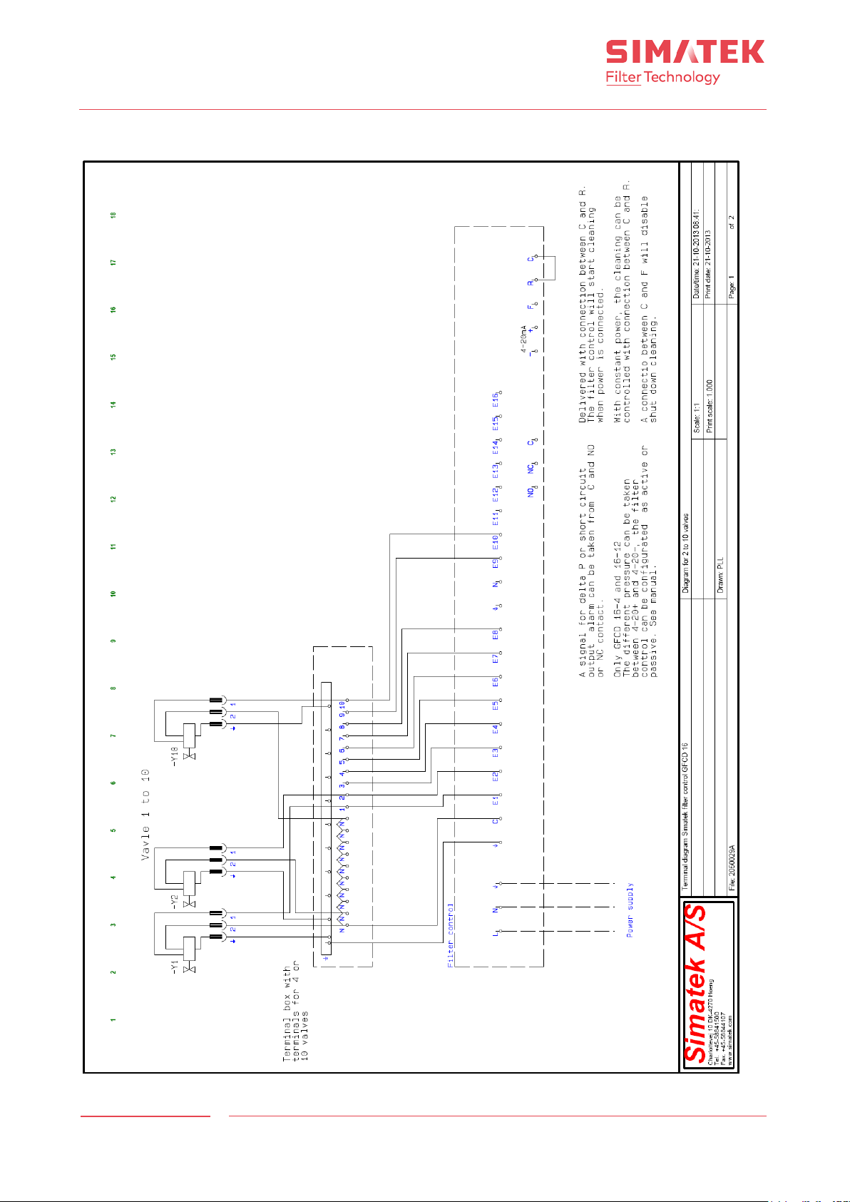
21. Electric diagram for Simatek GFCD 16: 2-10 valves
Rev.:
Page 17
Control Unit
SI MATE K A/ S
www.simatek.com
Hotline: +45 4046 7525
[email protected]
17
Doc. No.: 1400002_EN
-
Date: 04.2017
GFCD 16
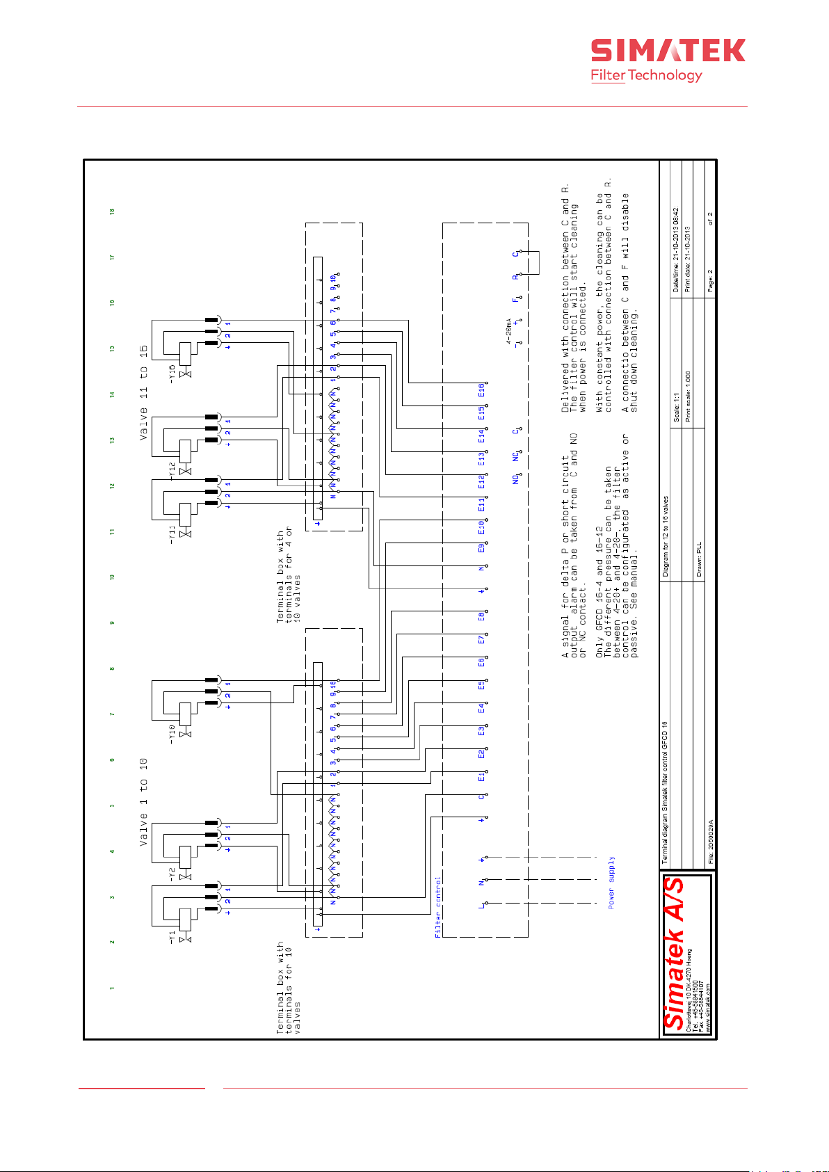
22. Electric diagram for Simatek GFCD 16: 12-16
Rev.:
Page 18
Control Unit
SI MATE K A/ S
www.simatek.com
Hotline: +45 4046 7525
[email protected]
18
Doc. No.: 1400002_EN
-
Date: 04.2017
GFCD 16
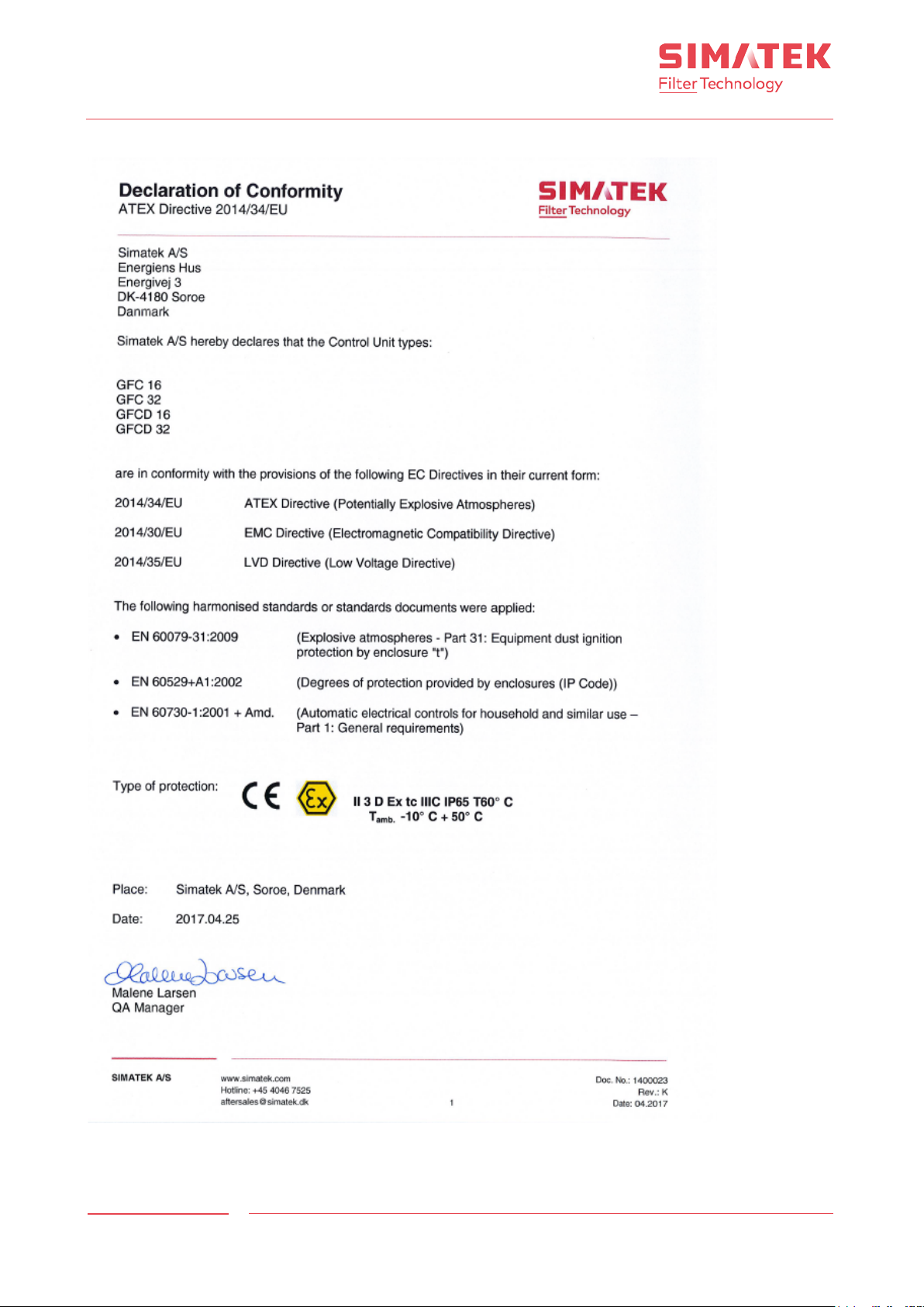
23. Declaration of Conformity
Rev.:
 Loading...