

Page 1
EN
S I M A R I N E
®
DE
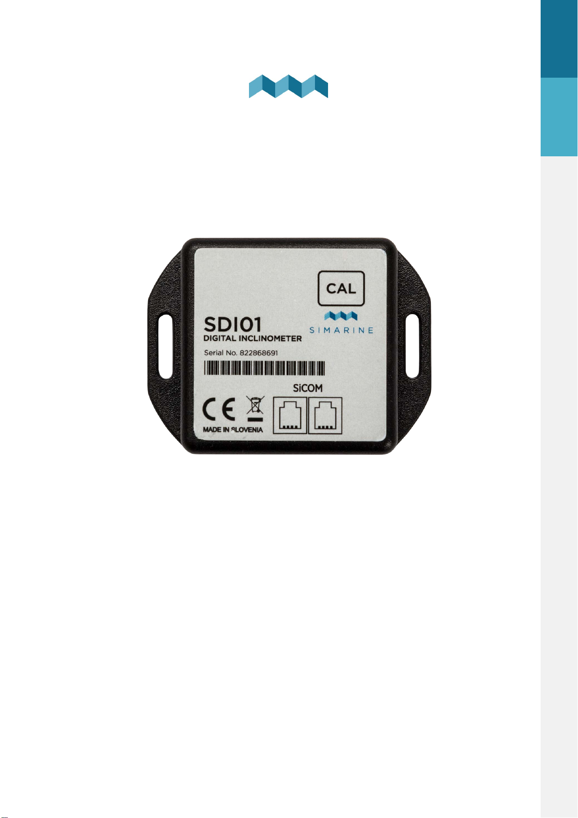
SDI01 Inclinometer
USERS MANUAL
V1.3
USER MANUAL - V1.3
Page 2

1.
Introduction .......................................................................... 3
2.
Safety .................................................................................... 3
3.
Overview .............................................................................. 4
4.
Instalation ............................................................................. 4
EN
4.1
5.
Cables ................................................................................................................. 4
Connecting a Digital Inclinometer Module to a
SIMARINE system ................................................................. 5
5.1
5.2
6.
7.
7.1
7.2
8.
8.1
8.2
8.3
Directly to the splitter ....................................................................................... 5
Through another module to the splitter ......................................................... 6
After connecting the module ................................................ 6
Calibration of the module ..................................................... 7
Calibration using the CAL button on the SDI01 module ................................. 7
Calibration through the monitor ...................................................................... 8
Configuring SDI01 inclinometer module ............................... 9
Name .................................................................................................................. 9
Nonlinear ........................................................................................................... 9
Display ................................................................................................................ 9
8.4
9.
10.
10.1
Reverse ............................................................................................................... 9
Technical specifications ...................................................... 10
Troubleshooting ................................................................. 10
Inclinometer not showing up on screen ........................................................ 10
SDI01 Inclinometer
2
Page 3

1. Introduction
SDI01 is a high-resolution digital inclinometer for pitch and roll with manual
calibration. It is fully compatible with existing SIMARINE monitoring systems. The
module was designed so that the configuration and calibration of the
inclinometer is quick and user friendly.
NOTE: Please make sure you are running a firmware version higher than version
3.000.
2. Safety
Only qualified electricians with proper safety equipment should make installation
of Simarine electronics. When working with batteries, you should wear protective
clothing and eye protection.
CAUTION: Batteries contain acid, a corrosive, colorless liquid that can burn your
eyes, skin, and clothing. If the acid comes into contact with eyes or skin, wash out
with lukewarm water and immediately seek medical support.
EN
CAUTION: Do NOT connect anything to a damaged battery. It could heat up,
catch fire, or explode.
CAUTION: Lead-acid batteries can generate explosive gases during operation.
Never smoke, allow flames, or sparks near the battery. Make sure to keep
sufficient ventilation around the battery.
3
SDI01 Inclinometer
Page 4
3. Overview
Cable length
Cable type
< 5m
No limitations
>= 5m
2x2x0.25 mm2 twisted pair (recommended)
EN
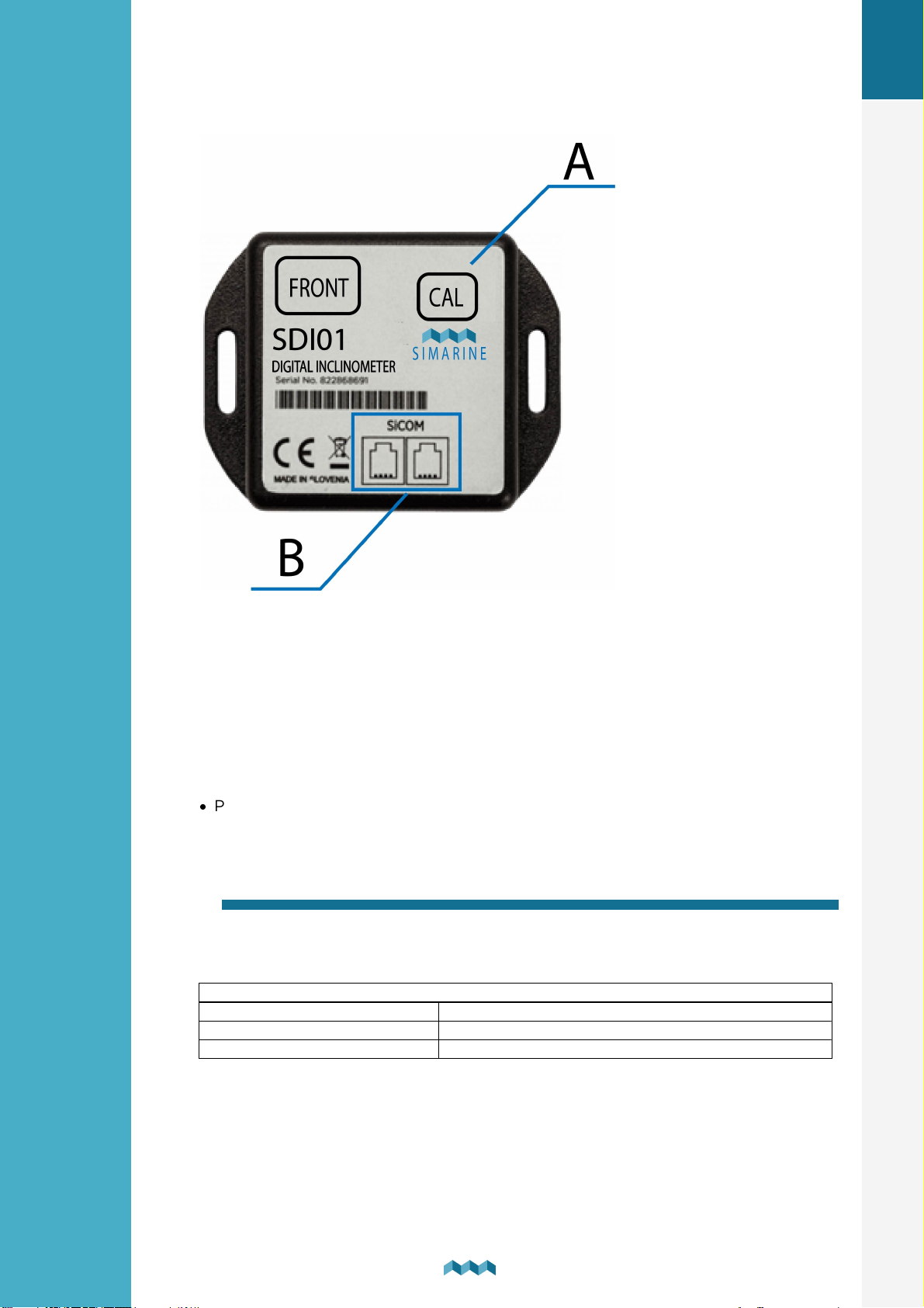
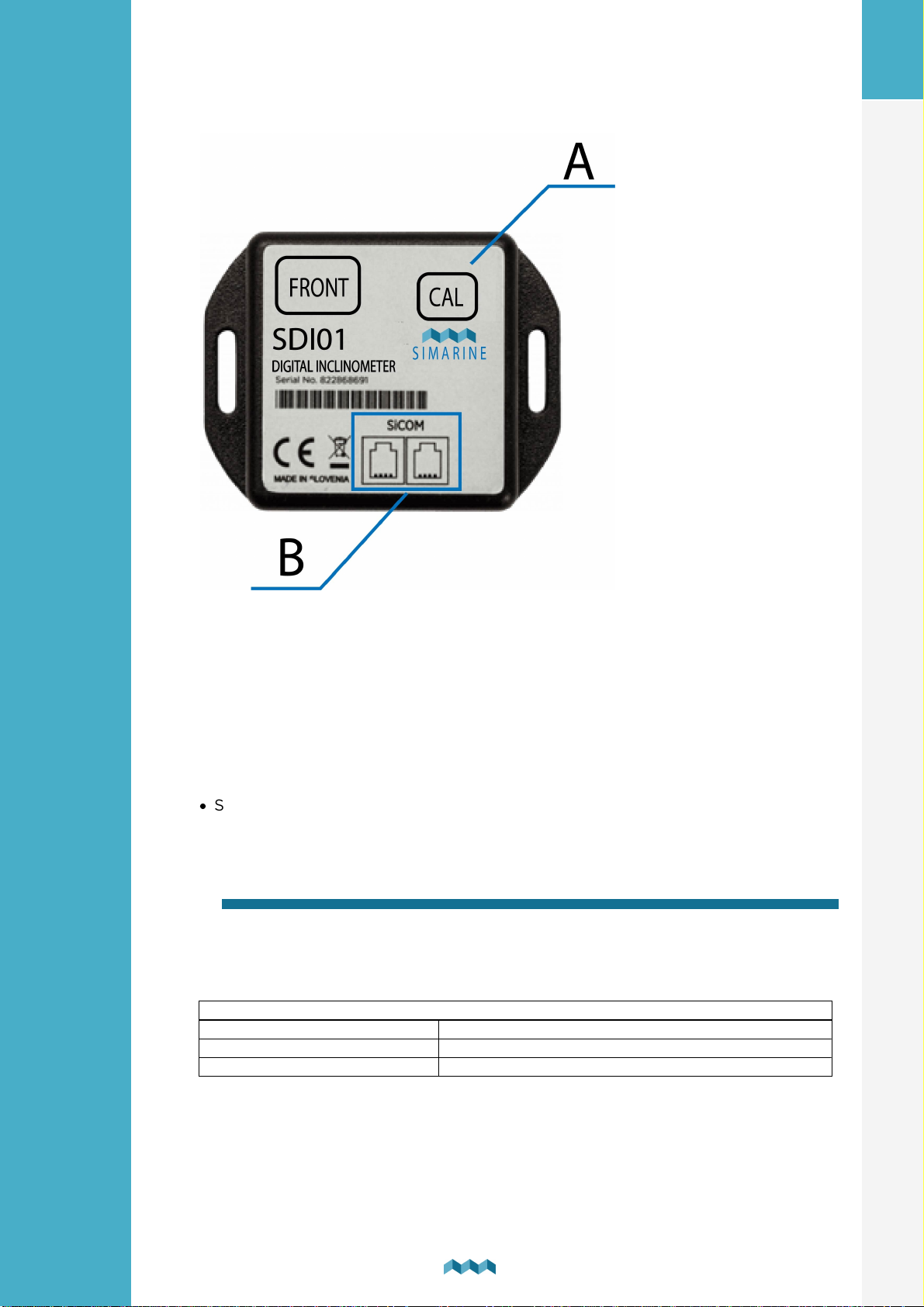
A - Calibration button
B - 2x SICOM port
4. Instalation
CAUTION: Install the shunt module in a clean and dry place protected from
accidental spilling of liquids.
·
Place the inclinometer on a firm and stable surface.
4.1
For the SiCOM connection, use the supplied cable. If not possible, use the
following table to determinate the correct cable type.
Cables
CABLES
SDI01 Inclinometer
4
Page 5
5. Connecting a Digital Inclinometer Module to a SIMARINE system
Like any other SIMARINE modules, the SDI01 also communicates with the
SIMARINE monitoring system through a SiCOM data cable, which is included with
the inclinometer.
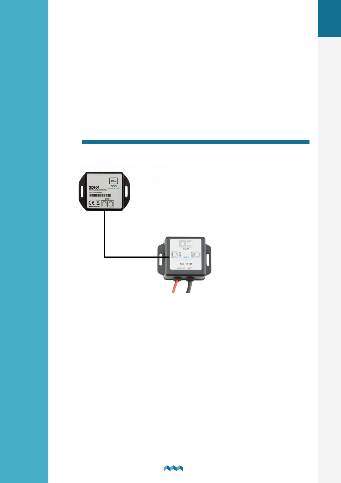
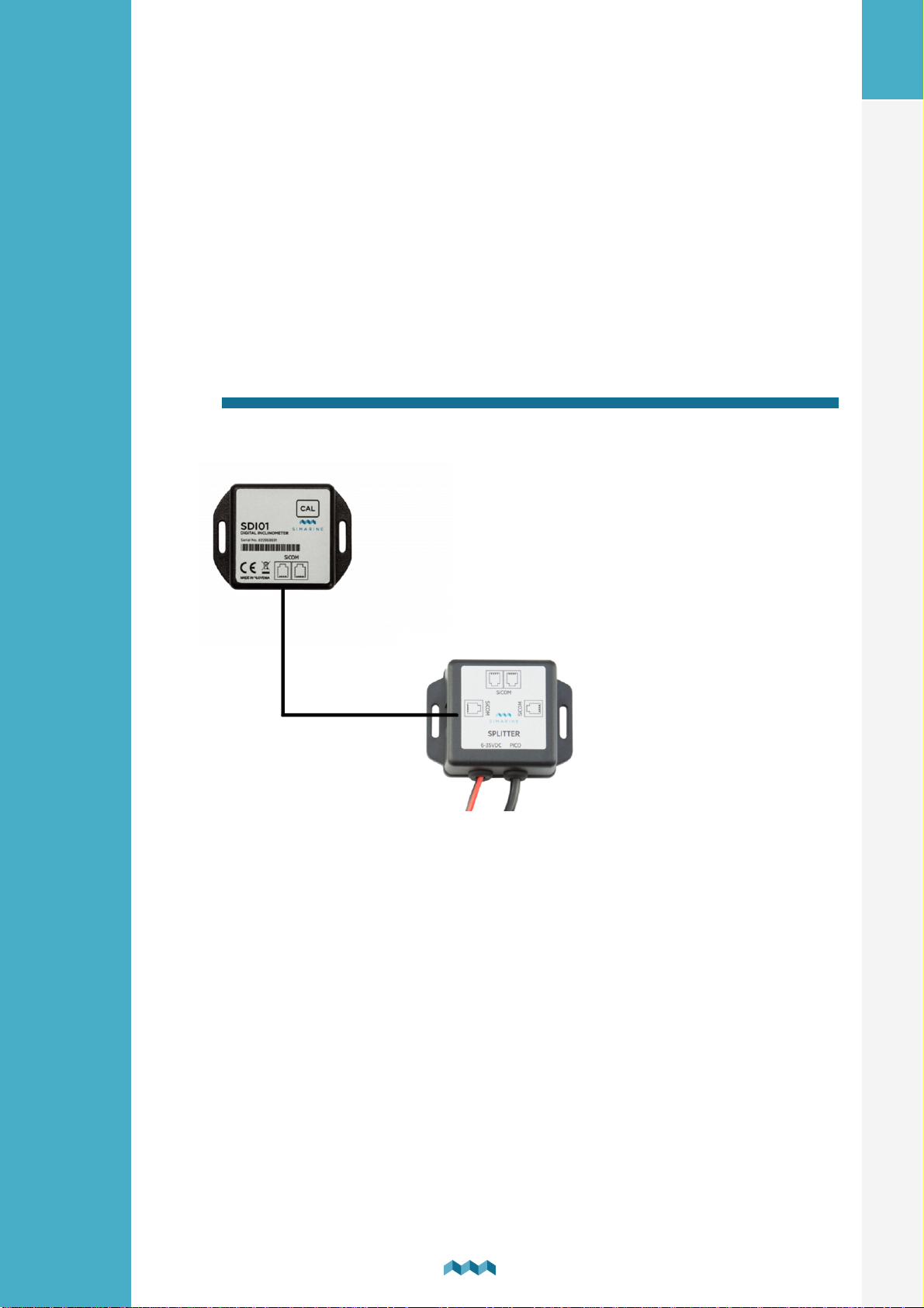
You can either connect the module directly to the SPLITTER or you can
connect it to another module which is already connected to the SPLITTER and
thus forming a so called “daisy chain” (indirect wiring).
5.1 Directly to the splitter
Connecting a digital inclinometer directly to the splitter port.
EN
STANDARD WIRING – DIRECTLY TO THE SPLITTER
5
SDI01 Inclinometer
Page 6
5.2 Through another module to the splitter
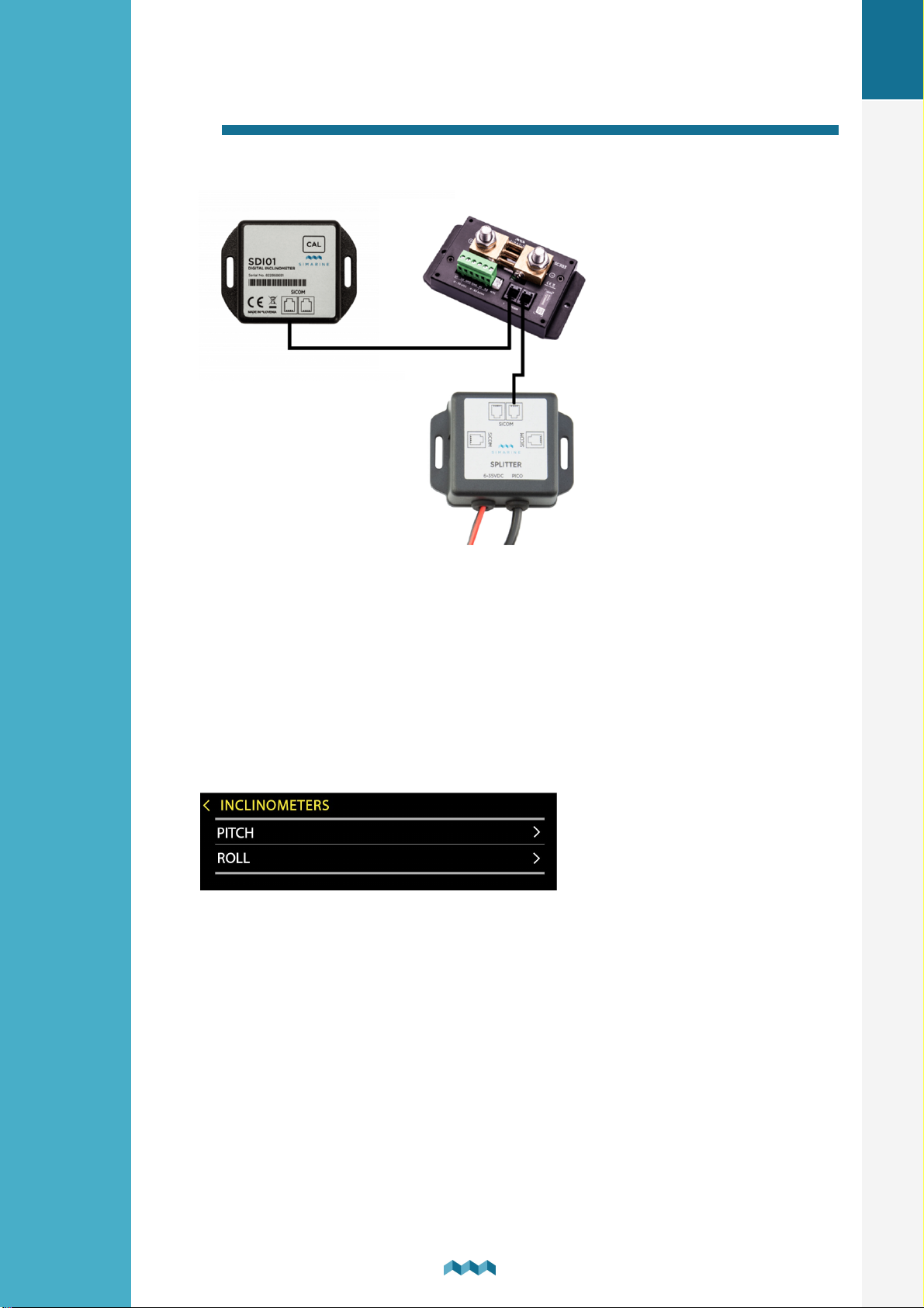
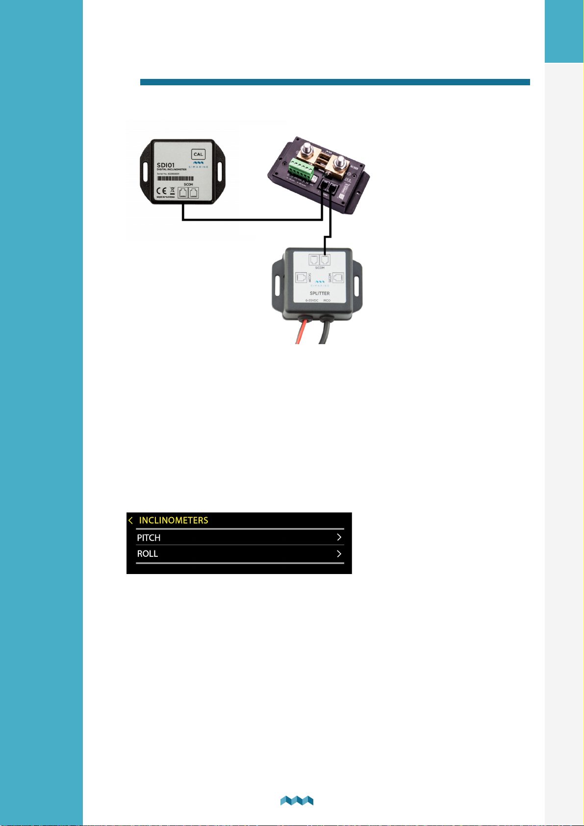
Connecting the inclinometer to another module to the splitter.
EN
INDIRECT WIRING – THROUGH ANOTHER MODULE TO THE SPLITTER
6.
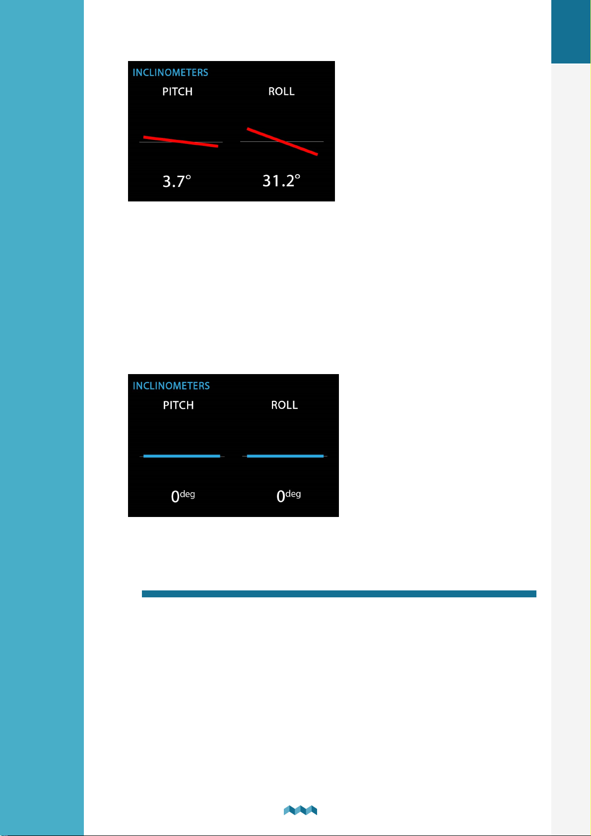
After connecting the module, your monitor will automatically recognize it and
configure two new inclinometer devices, which you can see in the list of
inclinometers MENU > DEVICES > INCLINOMETERS
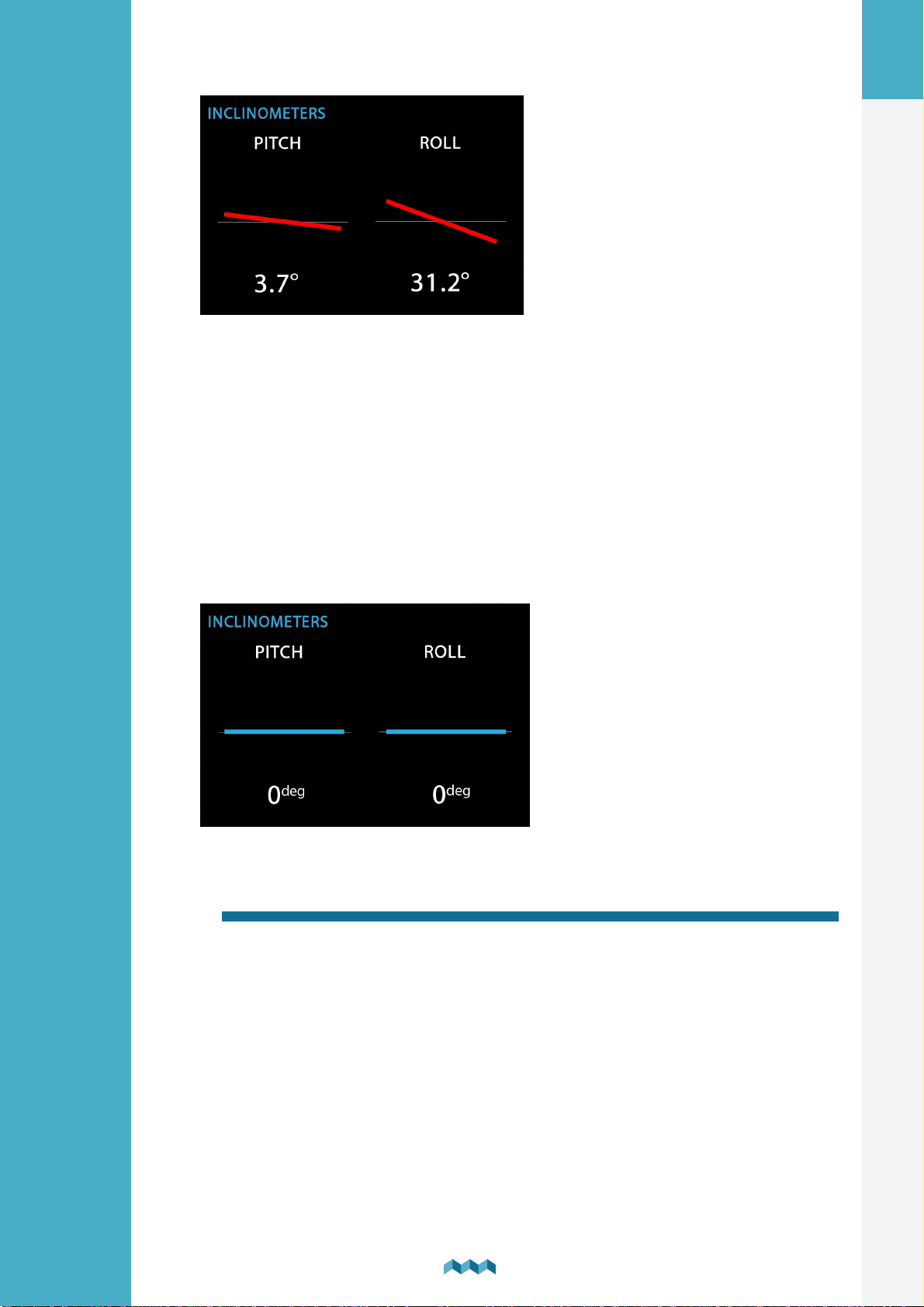
On the main screen, after scrolling down (using arrow-down button), past the
first screen, you will reach a new »Inclinometers« screen, which shows you the
current readings of your inclinometer module. Please note that at this step, due
to the lack of calibration, it is expected that the angle values are incorrect. The
process of calibrating your sensor is explained in the next section.
After connecting the module
6
SDI01 Inclinometer
Page 7
7. Calibration of the module
Before calibrating the module, you must make sure that the module is mounted in
its final position and the vehicle is parked on a level surface.
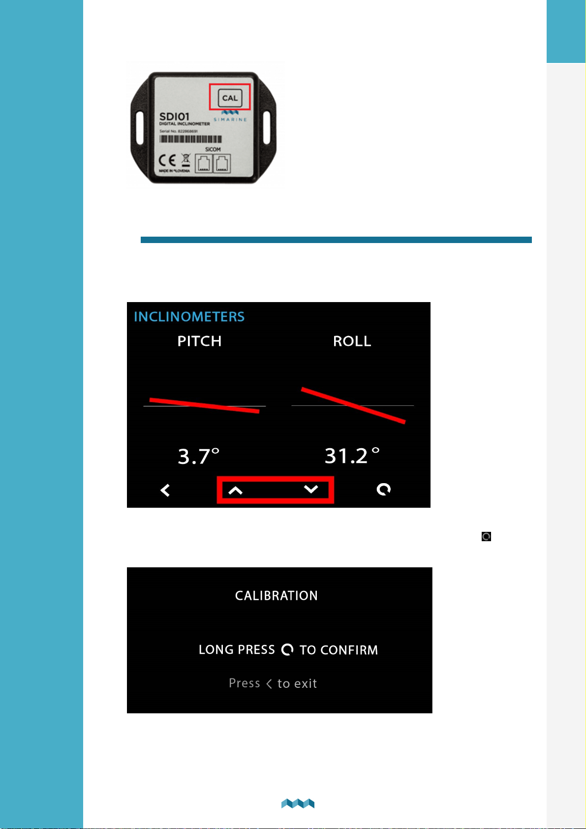
The calibration procedure can be executed in two ways. Either through the
monitor or by using a CAL button on the inclinometer module itself.
EN
The result of the calibration is 0° angles for both PITCH and ROLL inclinometers
at the current position of the module.
7.1 Calibration using the CAL button on the SDI01
module
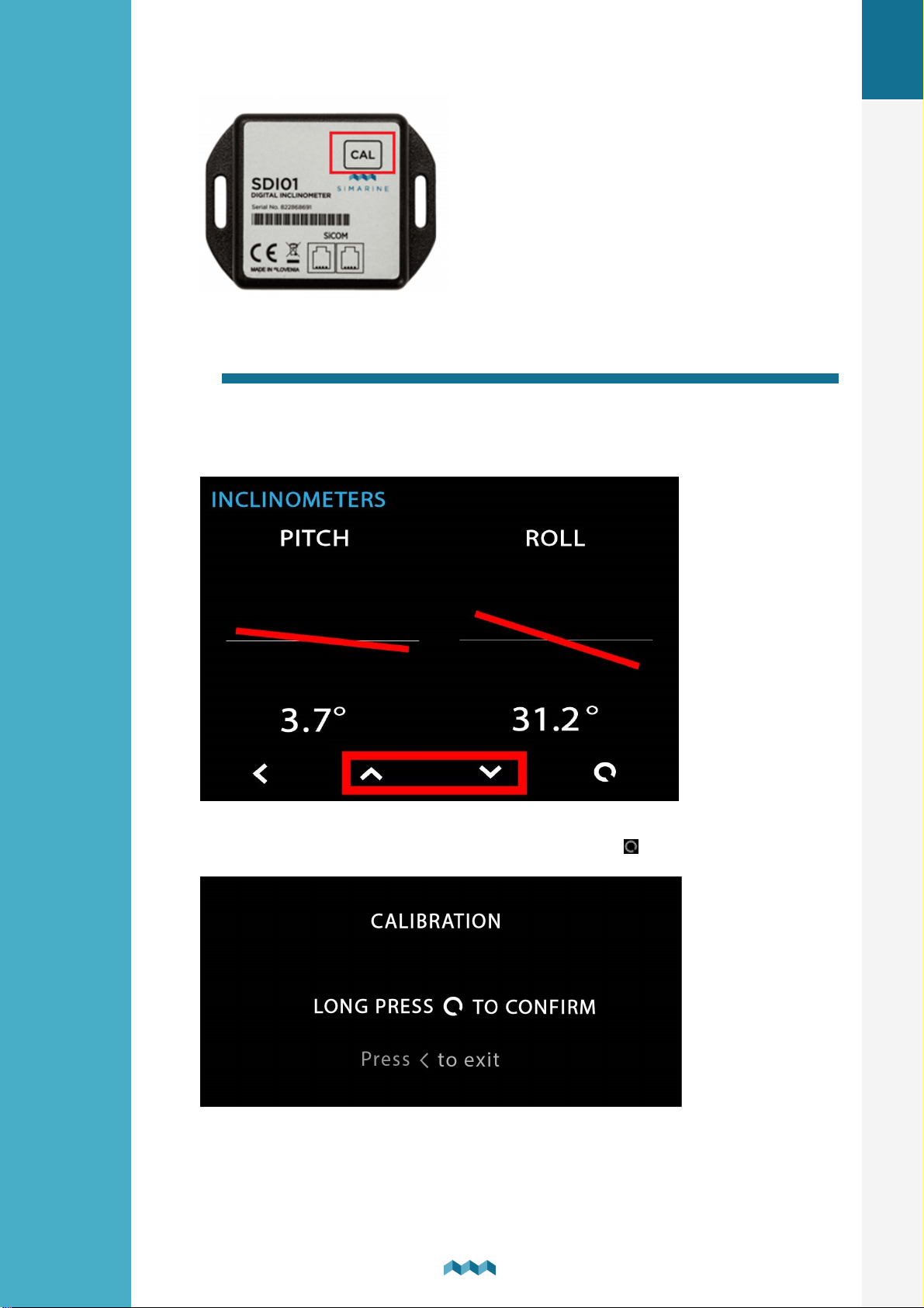
To calibrate the module using the CAL button, please press and hold the CAL
button which is located on the top right corner of the module. Hold the button
until the LED light on the module starts flashing red.
7
SDI01 Inclinometer
Page 8
7.2 Calibration through the monitor
To calibrate the module through the monitor, please navigate to the
inclinometers screen. Press and hold both up-arrow and down-arrow buttons
at the same time until the confirmation screen appears.
EN
After the conformation screen appears, long press the button to confirm.
8
SDI01 Inclinometer
Page 9
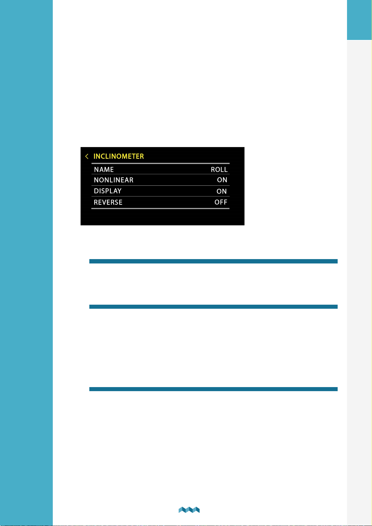
8. Configuring SDI01 inclinometer module
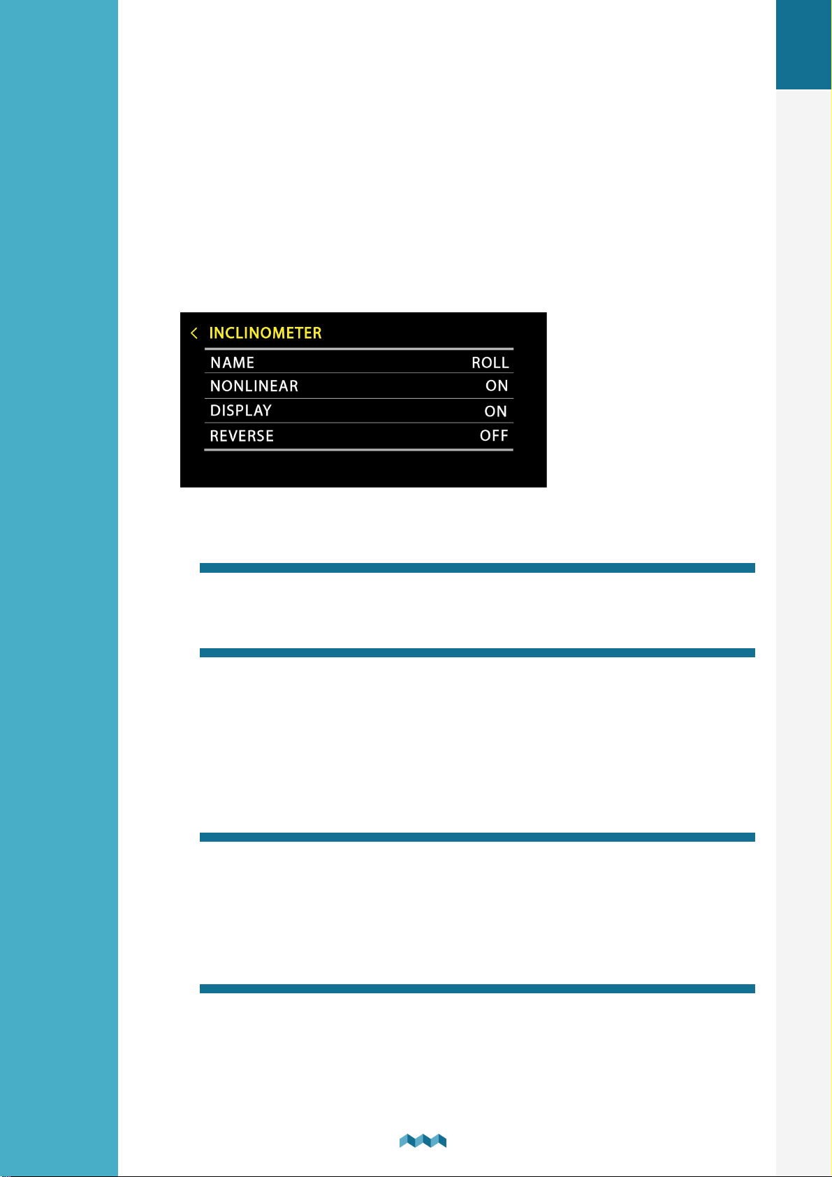
Although the module is designed so that is works more or less out of the box
(requiring only calibration), there is a variety of settings available for user to
configure.
EN
8.1
The display name of your inclinometer. You can select either PITCH or ROLL.
Name
8.2 Nonlinear
This parameter is for display purposes. By configuring NONLINEAR setting to
OFF, the inclination line will follow the angle values read by the sensor more
closely. This means that at the lower angles (1°–10°) the drawn offset may not be
as apparent.
The default value is ON.
8.3 Display
The parameter determines if the inclinometer is to be displayed on the
inclinometers screen.
The default value is ON.
8.4 Reverse
Reverses the display, which means that at the 5° angle the angle will be
presented as –5°. This gives the user more options when first mounting the
module to its location.
9
SDI01 Inclinometer
Page 10

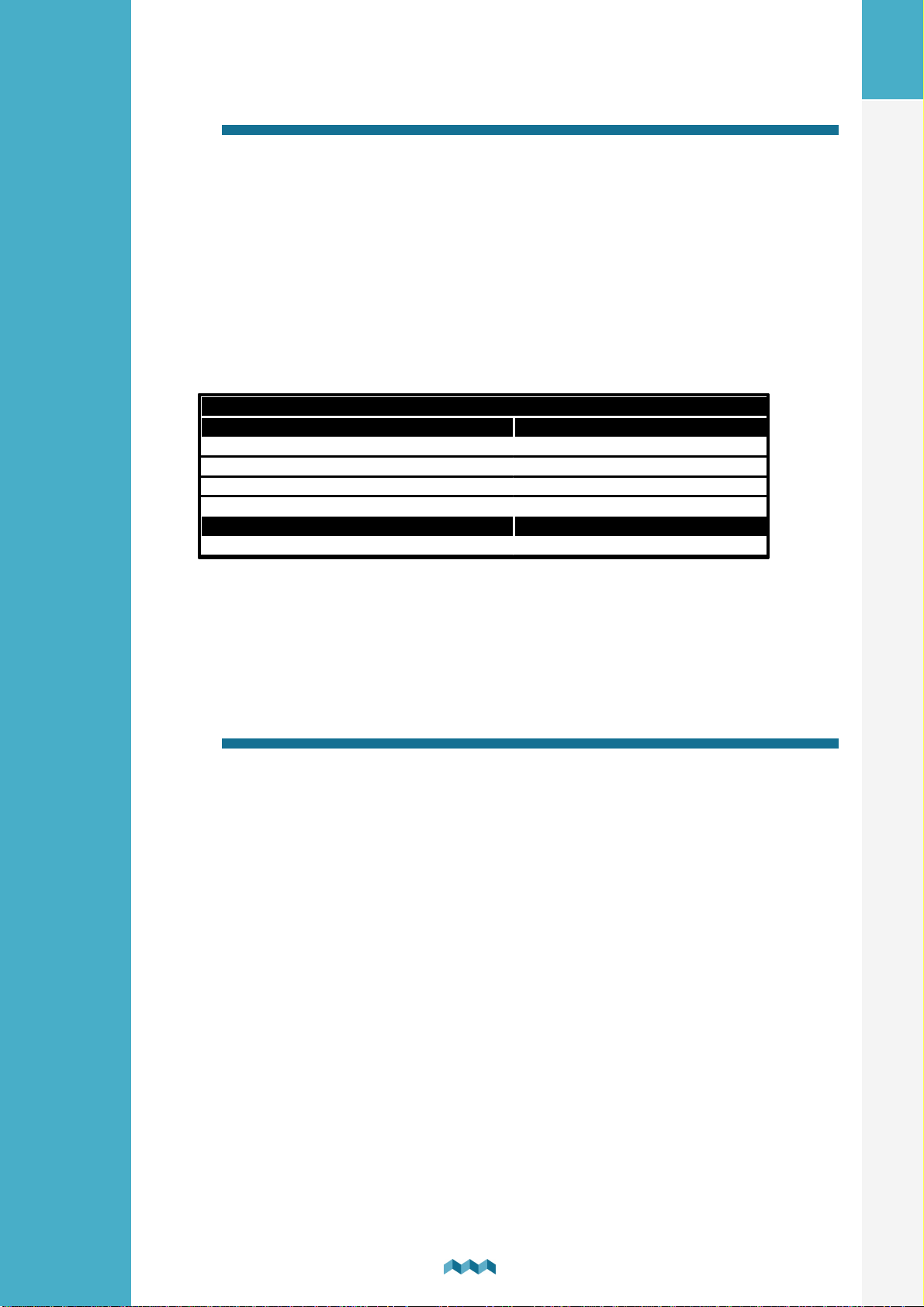
9. Technical specifications
SDI01
Operating
Voltage range
6 – 35 V
Resolution
0,1°
Output format
SiCOM
Range (putch&roll)
+-89°
Power consumption
Power consumption at 12V
1mA
EN
10. Troubleshooting
10.1
Make sure that the inclinometer module is connected to the SICOM input.
Inclinometer not showing up on screen
SDI01 Inclinometer
10
Page 11
DE
S I M A R I N E
®
SDI01 Inclinometer
Benutzerhandbuch
V1.2
- V 1.2
BENUTZERHANDBUCH
Page 12

1.
Einleitung .............................................................................. 3
2.
Sicherheit .............................................................................. 3
3.
Überblick .............................................................................. 4
4.
Einrichtung ............................................................................ 4
DE
4.1
5.
Kabel .................................................................................................................. 4
Anschluss eines digitalen Neigungsmessermoduls an
ein SIMARINE-System ........................................................... 5
5.1
5.2
6.
7.
7.1
7.2
8.
8.1
8.2
8.3
Directly to the splitter ....................................................................................... 5
Through another module to the splitter ......................................................... 6
Nach dem Anschließen des Moduls ...................................... 6
Kalibrierung des Moduls ....................................................... 7
Kalibrierung mit der CAL-Taste am SDI01-Modul ............................................ 7
Kalibrierung über den Monitor ........................................................................ 8
Neigungsmessermodul SDI01 konfigurieren ........................ 9
Name .................................................................................................................. 9
Nichtlinear ......................................................................................................... 9
Anzeige ............................................................................................................... 9
8.4
9.
10.
10.1
Umkehren ........................................................................................................ 10
Technische Einzelheiten ...................................................... 10
Fehlerbehebung .................................................................. 10
Inclinometer not showing up on screen ........................................................ 10
2
SDI01 Inclinometer
Page 13

1. Einleitung
SDI01 Inclinometer ist ein hochauflösender digitaler Neigungsmesser für Nickund Rollneigung mit manueller Kalibrierung. Es ist voll kompatibel mit
bestehenden SIMARINE-Überwachungssystemen. Das Modul wurde so
entworfen, dass die Konfiguration und Kalibrierung des Neigungsmessers schnell
und benutzerfreundlich sind.
HINWEIS: Bitte stellen Sie sicher, dass Sie eine Firmware-Version höher als
Version 3.000 verwenden.
2. Sicherheit
Nur qualifizierte Elektriker mit angemessener Sicherheitsausrüstung sollten die
Installation der Simarine-Elektronik vornehmen. Wenn Sie mit Batterien arbeiten,
sollten Sie Schutzkleidung und Augenschutz tragen.
VORSICHT: Die Batterien enthalten Säure, eine korrosive, farblose Flüssigkeit, die
Augen, Haut und Kleidung verbrennen kann. Falls Säure in Kontakt mit Augen
oder Haut kommt, waschen Sie sie mit lauwarmem Wasser und suchen Sie sofort
medizinische Unterstützung.
DE
VORSICHT: Schließen Sie NICHTS an eine beschädigte Batterie an. Sie könnte
aufheizen, Feuer fangen oder explodieren.
VORSICHT: Blei-Säure-Batterien können während des Betriebs explosive Gase
erzeugen. Rauchen Sie niemals in der Nähe der Batterie, und lassen Sie keine
Flammen oder Funken zu. Achten Sie darauf, dass eine ausreichende Belüftung
um die Batterie gegeben ist.
3
SDI01 Inclinometer
Page 14
3. Überblick
Kabellänge
Kabeltyp
< 5m
Keine Einschränkungen
>= 5m
2x2x0.25 mm2 verdrehtes Paar (empfohlen)
DE
A - Kalibrierungstaste
B - 2 SiCOM-Ports
4. Einrichtung
VORSICHT: Installieren Sie das Shunt-Modul an einem sauberen und trockenen
Ort, der vor versehentlichem Verschütten von Flüssigkeiten geschützt ist.
·
Stellen Sie den Neigungsmesser auf eine feste und stabile Oberfläche.
4.1
Für die SiCOM-Verbindung verwenden Sie das mitgelieferte Kabel. Wenn nicht
möglich, verwenden Sie die folgenden Tabelle, um den richtigen Kabeltyp zu
bestimmen.
Kabel
KABEL
SDI01 Inclinometer
4
Page 15
5. Anschluss eines digitalen Neigungsmessermoduls an ein SIMARINE-System
Wie alle anderen SIMARINE-Module kommuniziert auch das SDI01 mit dem
SIMARINE-Überwachungssystem über ein SiCOM-Datenkabel, das in der
Lieferung mit dem Neigungsmesser ankommt..
Sie können das Modul entweder anschließen direkt zum SPLITTER oder Sie
können es mit einem anderen Modul verbinden, das bereits mit dem SPLITTER
verbunden ist und so eine sogenannte „Daisy Chain“ (indirekte Verdrahtung)
bildet.
5.1 Directly to the splitter
Anschluss eines digitalen Neigungsmessers direkt an den Splitter-Port.
DE
STANDARDVERKABELUNG – DIREKT ZUM SPLITTER
5
SDI01 Inclinometer
Page 16
5.2 Through another module to the splitter
Anschließen des Neigungsmessers an ein anderes Modul an den Splitter.
DE
INDIREKTE VERKABELUNG – DURCH EIN ANDERES MODUL ZUM SPLITTER
6.
Nachdem Sie das Modul angeschloßen haben, erkennt Ihr Monitor es automatisch
und so werden zwei neue Neigungsmesser-Geräte konfiguriert, die Sie in der
Liste der Neigungsmesser sehen können. MENÜ > GERÄTE >
NEIGUNGSMESSER.
Auf dem Hauptbildschirm gelangen Sie nach dem Herunterscrollen (mit der Pfeilnach-unten-Taste) über den ersten Bildschirm hinaus zu einem neuen
„Neigungsmesser“ Bildschirm, der Ihnen die aktuellen Messwerte Ihres
Neigungsmessermoduls anzeigt. Bitte beachten Sie, dass in diesem Schritt
aufgrund der fehlenden Kalibrierung erwartet wird, dass die Winkelwerte falsch
sind. Die Kalibrierung Ihres Sensors wird im nächsten Abschnitt erläutert.
Nach dem Anschließen des Moduls
6
SDI01 Inclinometer
Page 17
7. Kalibrierung des Moduls
Bevor Sie das Modul kalibrieren, müssen Sie sicherstellen, dass das Modul in seiner
endgültigen Position montiert ist und das Fahrzeug auf einer ebenen Fläche
abgestellt ist.
Das Kalibrierverfahren kann auf zwei Arten ausgeführt werden. Entweder über
den Monitor oder über eine CAL-Taste am Neigungsmessermodul selbst.
DE
Das Ergebnis der Kalibrierung sind 0°-Winkel sowohl für PITCH- als auch für
ROLL-Neigungsmesser an der aktuellen Position des Moduls.
7.1 Kalibrierung mit der CAL-Taste am SDI01-Modul
Um das Modul mit der CAL-Taste zu kalibrieren, halten Sie bitte die CAL-Taste in
der oberen rechten Ecke des Moduls gedrückt. Halten Sie die Taste gedrückt bis
das LED-Licht am Modul rot zu blinken beginnt.
7
SDI01 Inclinometer
Page 18
7.2 Kalibrierung über den Monitor
Um das Modul über den Monitor zu kalibrieren, navigieren Sie bitte zum
Bildschirm Neigungsmesser. Halten Sie die Aufwärts- und Abwärtspfeiltaste
gleichzeitig gedrückt bis der Bestätigungsbildschirm erscheint.
DE
Nachdem der Bestätigungsbildschirm angezeigt wird, drücken Sie lange die
Taste zum Bestätigen.
8
SDI01 Inclinometer
Page 19
8. Neigungsmessermodul SDI01 konfigurieren
Obwohl das Modul so entworfen ist, dass es mehr oder weniger sofort
funktioniert (nur Kalibrierung erforderlich), stehen dem Benutzer eine Vielzahl von
Einstellungen zur Verfügung.
DE
8.1
Der Anzeigename Ihres Neigungsmessers. Sie können zwischen diesen beiden
wählen: PITCH oder ROLL.
Name
8.2 Nichtlinear
Dieser Parameter dient zur Anzeige. Durch die Konfiguration von der
NICHTLINEAR Einstellung auf OFF, folgt die Neigungslinie den vom Sensor
gelesenen Winkelwerten genauer. Das bedeutet, dass bei den unteren Winkeln
(1°–10°) der gezeichnete Versatz möglicherweise nicht so offensichtlich ist.
Der Standardwert ist auf ON.
8.3 Anzeige
Dieser Parameter bestimmt, ob der Neigungsmesser auf dem NeigungsmesserBildschirm angezeigt werden soll.
Der Standardwert ist auf ON.
9
SDI01 Inclinometer
Page 20
8.4 Umkehren
SDI01
In Betrieb
Spannungsbereich
6–35V
Auflösung
0,1°
Ausgabeformat
SiCOM
Reichweite (Pitch & Roll)
+/–89°
Stromverbrauch
Stromverbrauch bei 12V
1mA
Kehrt die Anzeige um, das bedeutet, dass bei einem Winkel von 5° der Winkel als
–5° dargestellt wird. Das ermöglicht dem Benutzer eine größere Auswahl, wenn
er das Modul zum ersten Mal an seinem Standort anbringt.
DE
9.
Technische Einzelheiten
10. Fehlerbehebung
10.1 Inclinometer not showing up on screen
Stellen Sie sicher, dass das Neigungsmessermodul an dem SICOM-Anschluss
angeschlossen ist.
SDI01 Inclinometer
10
 Loading...