

Page 1
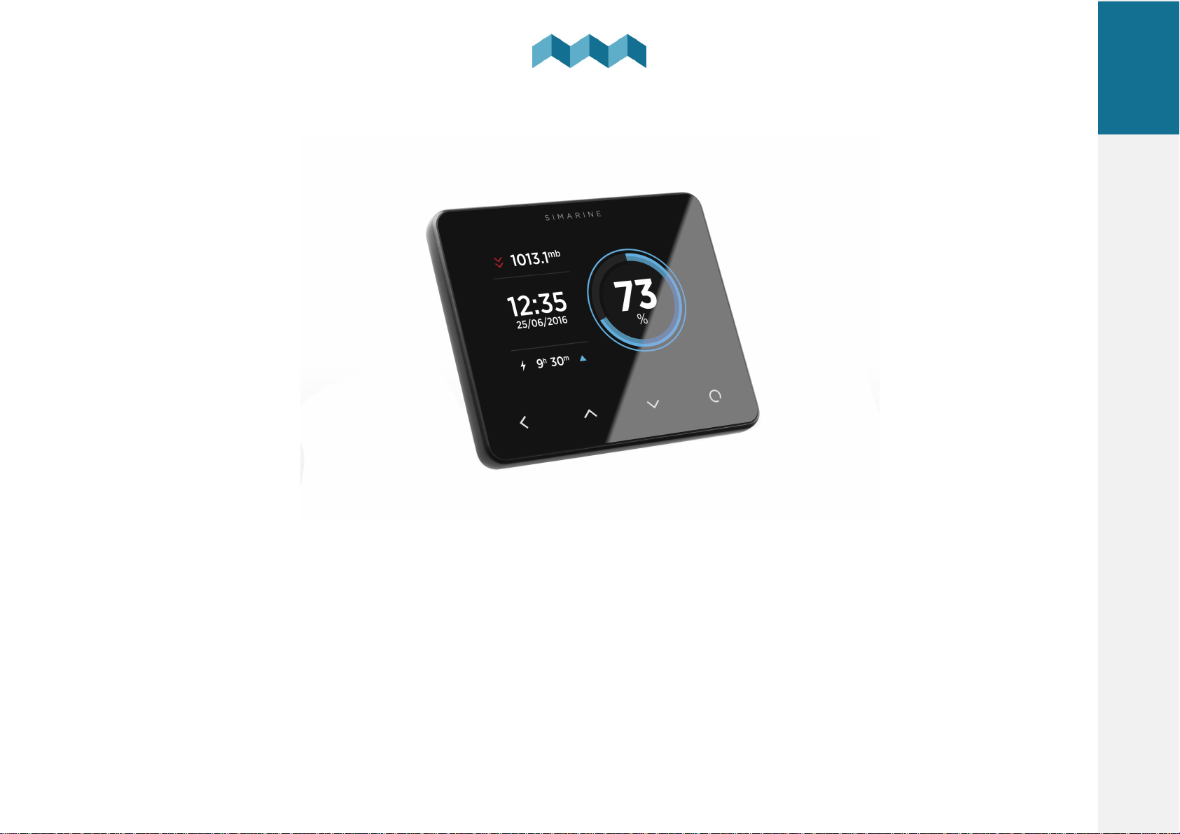
S I M A R I N E
EN
®
PICO
USER MANUAL
V8.0
- V 8.0
USER MANUAL
Page 2

EN
PICO
© 2023 SIMARINE
All rights reserved. No parts of this work may be reproduced in any form or by any means - graphic, electronic, or mechanical,
including photocopying, recording, taping, or information storage and retrieval systems - without the written permission of the
publisher.
Products that are referred to in this document may be either trademarks and/or registered trademarks of the respective owners.
The publisher and the author make no claim to these trademarks.
While every precaution has been taken in the preparation of this document, the publisher and the author assume no responsibility
for errors or omissions, or for damages resulting from the use of information contained in this document or from the use of
programs and source code that may accompany it. In no event shall the publisher and the author be liable for any loss of profit or
any other commercial damage caused or alleged to have been caused directly or indirectly by this document.
EN
PICO
Page 3

1.
Introduction .............................................................................................................................. 7
EN
1.1
About ....................................................................................................................................................................................................... 8
Accessories ............................................................................................................................... 92.
Safety ..................................................................................................................................... 113.
Declaration of conformity ......................................................................................................... 134.
5.
Installation .............................................................................................................................. 15
5.1
5.1.1
5.1.2
5.2
5.2.1
6.
PICO Mounting ...................................................................................................................................................................................... 16
PICO Standalone ............................................................................................................................................................................ 17
PICO Panel-mount .......................................................................................................................................................................... 18
Connecting ............................................................................................................................................................................................. 19
Connecting different shunts .......................................................................................................................................................... 19
Basic Setup .............................................................................................................................. 21
6.1
6.2
6.3
6.4
6.5
6.5.1
Voltmeters ............................................................................................................................................................................................. 22
Ohmeters ............................................................................................................................................................................................... 22
Settings Screen ...................................................................................................................................................................................... 23
Start screen after first connection ........................................................................................................................................................ 24
Battery configuration ............................................................................................................................................................................ 25
Technical specifications
Adding a new battery ..................................................................................................................................................................... 25
12
3
Page 4

EN
6.5.2
6.6
6.6.1
6.7
6.7.1
6.8
6.8.1
6.9
6.9.1
6.10
6.10.1
7.1
Advanced settings .......................................................................................................................................................................... 27
Tank configuration ................................................................................................................................................................................ 29
Adding a new tank ......................................................................................................................................................................... 29
Temperature sensor configuration ...................................................................................................................................................... 31
Adding a temperature sensor ........................................................................................................................................................ 31
Inclinometer configuration ................................................................................................................................................................... 31
Adding a new inclinometer ............................................................................................................................................................ 32
User sensor configuration .................................................................................................................................................................... 32
Adding a new user sensor .............................................................................................................................................................. 33
Current sensors configuration .............................................................................................................................................................. 33
Current sensors .............................................................................................................................................................................. 33
Screens ................................................................................................................................... 377.
Batteries screen ..................................................................................................................................................................................... 38
7.2
7.3
7.4
7.5
7.6
7.7
8.
Tanks screen .......................................................................................................................................................................................... 39
Temperatures screen ............................................................................................................................................................................ 40
Barograph screen .................................................................................................................................................................................. 41
Inclinometers screen ............................................................................................................................................................................. 42
User Sensors Screen .............................................................................................................................................................................. 43
Alarms screen ........................................................................................................................................................................................ 44
Device configuration ................................................................................................................ 45
4
Basic Setup
6.
Page 5

EN
8.1
8.2
8.3
8.4
8.1.1
8.1.2
8.1.3
8.1.4
8.3.1
8.3.2
8.3.3
8.3.4
8.3.5
8.3.6
General settings ..................................................................................................................................................................................... 46
Screen ............................................................................................................................................................................................. 46
Device ............................................................................................................................................................................................. 47
Language ........................................................................................................................................................................................ 47
Units ............................................................................................................................................................................................... 47
Data management ................................................................................................................................................................................. 48
Devices ................................................................................................................................................................................................... 49
Batteries ......................................................................................................................................................................................... 49
Tanks .............................................................................................................................................................................................. 50
Temperature sensors ..................................................................................................................................................................... 50
Coulomb counter ........................................................................................................................................................................... 50
Inclinometer ................................................................................................................................................................................... 51
User sensors .................................................................................................................................................................................... 51
WI-FI ....................................................................................................................................................................................................... 51
8.4.1
8.4.2
8.5
8.6
8.7
9.
Mobile application ................................................................................................................... 57
10.
Save and restore settings ......................................................................................................... 59
AP Mode ......................................................................................................................................................................................... 52
STA Mode ....................................................................................................................................................................................... 53
Date and time ........................................................................................................................................................................................ 54
System .................................................................................................................................................................................................... 55
Service .................................................................................................................................................................................................... 55
5
Device configuration
8.
Page 6

Firmware upgrade ................................................................................................................... 6111.
12.
Technical specifications ............................................................................................................ 63
EN
6
Firmware upgrade
11
Page 7

1
Introduction
Page 8
1. Introduction
Congratulations on your purchase of the PICO Battery Monitor.
Simarine developed a state of the art DC Battery monitor. PICO is a water and dust resistant device used to monitor DC
power sources as batteries and solar panels. The information is displayed on a large 3,5” high resolution IPS display with
Gorilla® Glass and anti-reflective coating to ensure superior visibility.
PICO is capable of monitoring up to 6 batteries (battery banks), 14 tanks, 14 temperatures and 20 independent current
sensors (shunts).
PICO is equipped with a Wi-Fi module to communicate with the Simarine application available for Android™ and
iPhone® smartphones. The app allows accessing live data, analyzing historical data, configuring PICO and perform a
firmware upgrade of PICO.
EN
1.1
About
In this manual we will show you how to install the PICO and configure the settings.
You will find more information on other shunts, modules installations, devices, on the website: https://simarine.net/manuals
Introduction
8
1.
Page 9

2
Accessories
Page 10

2. Accessories
PICO is compatible with the following SIMARINE modules:
·
SC303 Digital Shunt – 300A Shunt, for up to 75V systems.
·
SC503 Digital Shunt – 500A Shunt, for up to 75V systems.
·
SDI01 Inclinometer – High-resolution digital inclinometer for pitch and roll with manual calibration.
·
SCQ25 Quadro Digital Shunt Module – 4x25A Shunt, for 12V and 24V systems
·
SCQ50 Quadro Digital Shunt Module – 4x50A Shunt, for 12V and 24V systems.
·
SCQ25T Quadro Digital Shunt and Analog input module 4x25A Shunt and Analog input module with 4 resistance and 3
voltage inputs.
·
ST107 Analog input interface module with 4 resistance and 3 voltage Inputs.
EN
10
Accessories
2.
Page 11

3
Safety
Page 12

3. Safety
Electrical specialists with proper safety equipment should make installation of Simarine electronics. When working with
batteries, you should wear protective clothing and eye protection.
CAUTION: Batteries contain acid, a corrosive, colorless liquid that will burn your eyes, skin, and clothing. Should the acid
come in contact with eyes, skin or clothing, wash it immediately with soap under fresh water for at least 15 minutes, and seek
medical support immediately.
CAUTION: Do NOT connect anything to a damaged battery. It could heat up, catch fire or explode.
CAUTION: Lead-acid batteries can generate explosive gases during operation. Never smoke, allow flames or sparks near the
battery. Make sure to keep sufficient ventilation around the battery.
CAUTION: When working with a battery, remove all personal metal items like watches, rings, necklaces, and bracelets. Metal
items in contact with the battery terminals might cause a short circuit with a very high electric current, which may heat up
and melt nearby objects and cause severe burns.
EN
12
Safety
3.
Page 13

4
Declaration of conformity
Page 14

4. Declaration of conformity
MANUFACTURER: SIMARINE d.o.o.
ADDRESS: Ulica škofa Maksimilijana Držecnika 6, SI-2000 Maribor, Slovenia, EU
Declares that the following product:
PRODUCT TYPE: PICO
Conforms to the requirements of the following Directives of the European Union:
EMC Directive 2014/30EU, RoHS Directive 2002/95/EC
The above product conforms with the following harmonized
standards: EN61000-6-3: 2001 EMC - Generic Emissions Standard,
EN61000-6-2: 2005 EMC Generic Immunity Standard
EN
14
Declaration of conformity
4.
Page 15

5
Installation
Page 16

5. Installation
EN
5.1
PICO Mounting
PICO should be installed in a visible place to provide good readability.
Please note that ONLY the PICO display unit is water and dust resistant! Any other
modules including splitter shouldn't expose to high humidity or liquids in any case.
The mounting process and installation cutouts depend on the model, as
described in following sections.
16
Installation
5.
Page 17
5.1.1 PICO Standalone
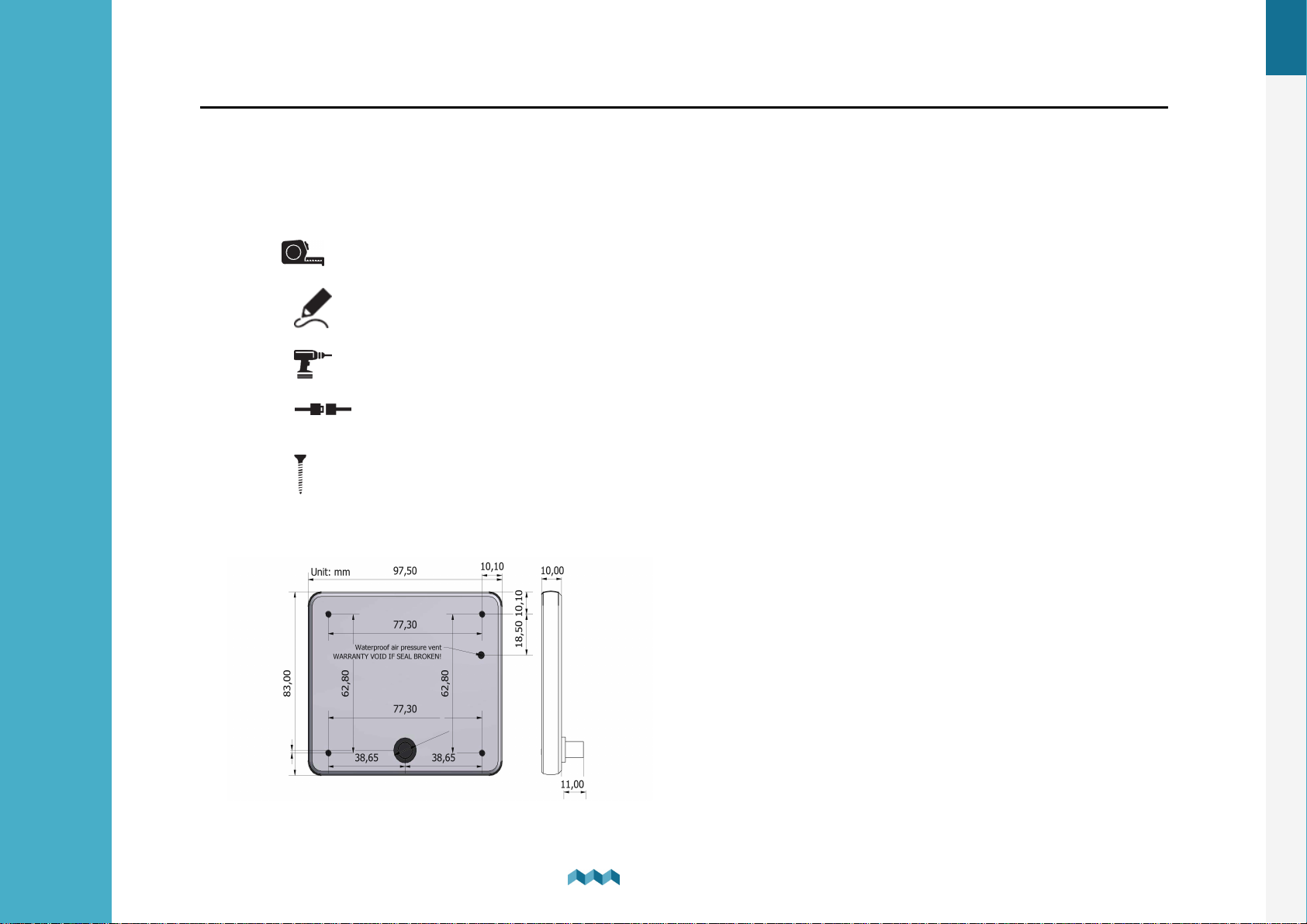
PICO Standalone version has dimensions of 98 x 84 x 10 mm (3.85 x 3.30 x 0.39 in)
and needs NO installation cutout.
The mounting process requires drilling of 6 mounting holes and access to the rear
of the mounting surface. In case you have NO rear access, you can bond it using
supplied double sided tape.
1. Before drilling, check if there is enough space to mount your PICO.
2. Mark mounting holes using the supplied installation template.
3. Drill all holes.
4.
fasten it by turning the safety ring clockwise.
5. Finish mounting the PICO from the back side with the supplied threaded rod and nuts. Screws, rods and
nuts MUST be fastened by hand. Excessive force may damage the threads on PICO.
Connect the connector on the back side of PICO to the splitter cable (be sure to align the pins correctly) and
EN
17
Installation
5.
Page 18
5.1.2 PICO Panel-mount
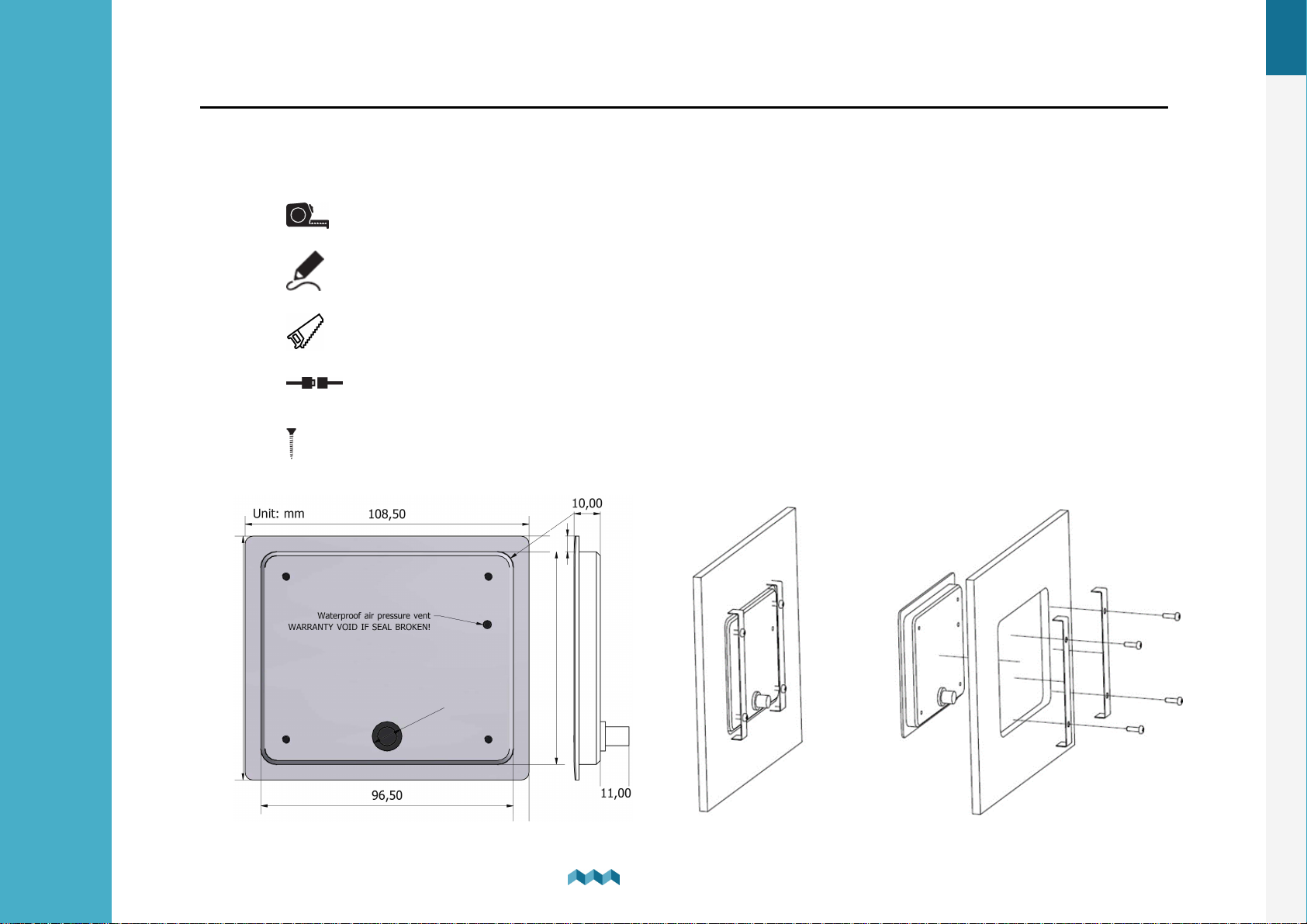
PICO Panel-mount version dimensions are 108.5 x 94 x 10 mm (4.27 x 3.70 x 0.39 in). It needs an installation cutout of 98 x
83mm. It can be mounted with supplied threaded rods and brackets or bonded with adhesive if there is no rear access to the
mounting surface.
1. Before cutting out, check if there is enough space for your PICO.
2. Mark the cutout line with the supplied installation template.
3. Using a saw, carefully cut out the marked area.
4. Connect the connector on the back side of PICO to the splitter cable (be sure to align the pins correctly)
and fasten it by turning the safety ring clockwise.
5. Finish mounting the PICO from the back side with the supplied threaded rod and nuts. Screws, rods and
nuts MUST be fastened by hand. Excessive force may damage the threads on PICO.
EN
18
Installation
5.
Page 19

EN
Cable length
Cable type
< 5m
No limitations
>= 5m
2 x 2 x 0.25mm2 Twisted pair (recommended)
5.2
Connecting
SiCOM data cable - For the SiCOM connection use the supplied cable. If not possible, use the following table to determinate
the right cable type.
PICO connects to the SiCOM bus via attached Splitter, which is a SiCOM bus entry point for other devices and the power
connection. Splitter must connect to the power source (6-35V) with the red/black cable. It is recommended to connect the
power cable behind the main switch, so you can power off the complete system, although the total power consumption of
the system is very low (usually <100mA at normal operation).
5.2.1
You can find the information of all the latest Simarine Digital shunts / modules on the website:
https://www.simarine.net/manuals
For 12V and 24V systems you can wire your shunts on either the positive or the negative side of the system. For higher
voltages (above 35V), wiring to the negative side is mandatory.
Connecting different shunts
Installation
5.
19
Page 20

6
Basic Setup
Page 21
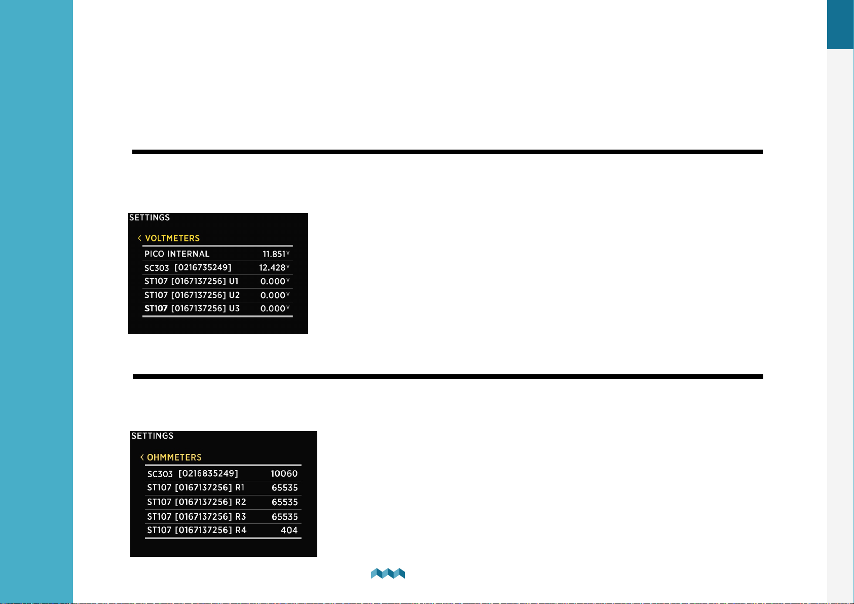
6. Basic Setup
PICO’s menu management is transparent and easy to use. All changes can be done using four touch buttons below the
screen. Menus and settings can differ from your device since future firmware upgrades might cause some minor changes in
the menus and settings.
EN
6.1
Voltmeters
List of all voltmeter sensors connected to your PICO. Connected voltmeters are added to the list automatically.
In this list, you can view real time readings (voltages) for all connected voltmeters.
6.2
Ohmeters
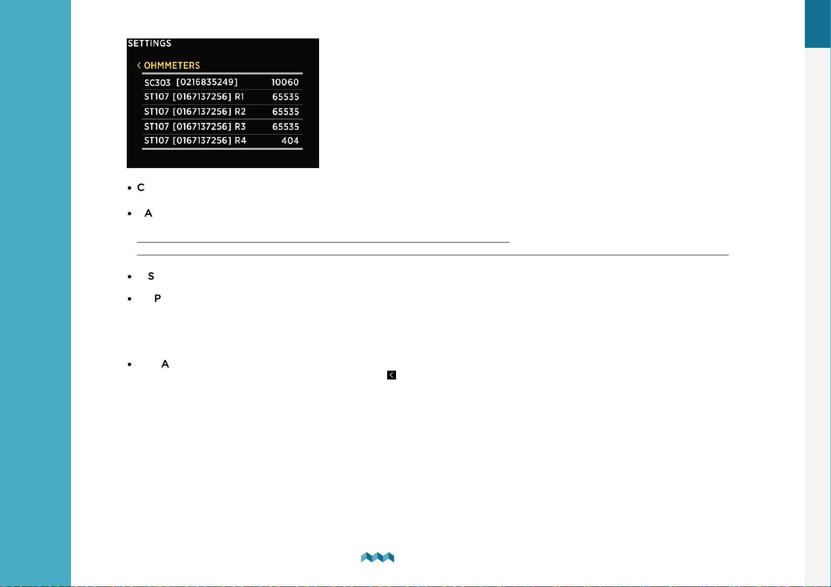
List of all ohmmeters connected to PICO. Connected ohmmeters are added to the list automatically. You cannot manually
add a new ohmmeter. In this list, you can view current readings (resistance in ohms) for all connected ohmmeters.
22
Basic Setup
6.
Page 22
EN
6.3
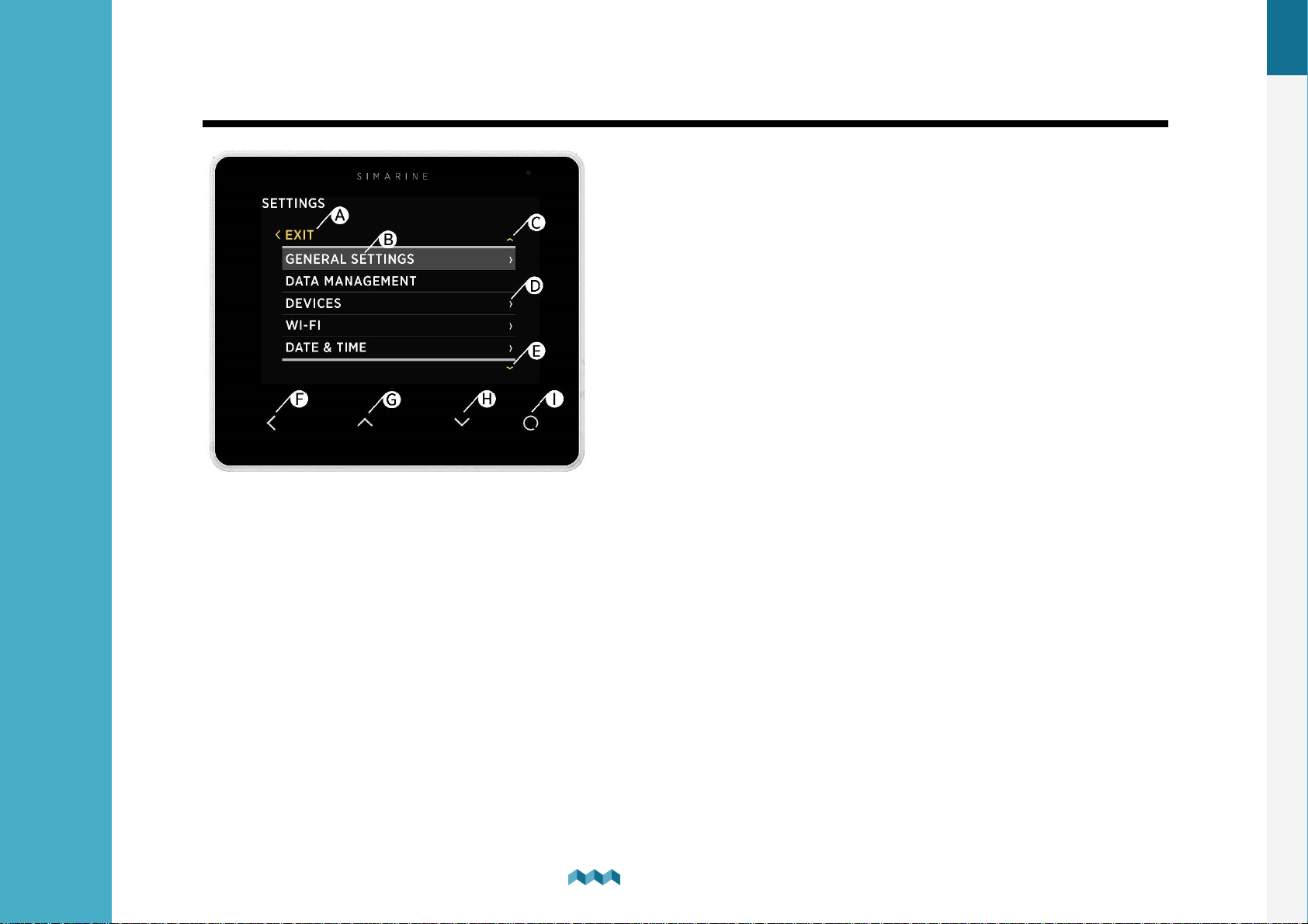
Settings Screen
A – Label indicates current position in the menu.
B – Currently selected item.
C – Arrow indicates there is at least one more menu item in the arrow direction.
D – Arrow indicates there is a submenu.
E – Arrow indicates there is at least one more menu item in the arrow direction.
F- BACK BUTTON, is used to navigate one level back ore leave the settings menu.
G – UP BUTTON is used to navigate up in the menu or changing value or switching screens in live view.
H – DOWN BUTTON is used to navigate down in the menu or changing value or switching screens in live
view.
I – ENTER BUTTON, long press activates settings, short press commits changes or enters selected submenu.
23
Basic Setup
6.
Page 23
EN
6.4
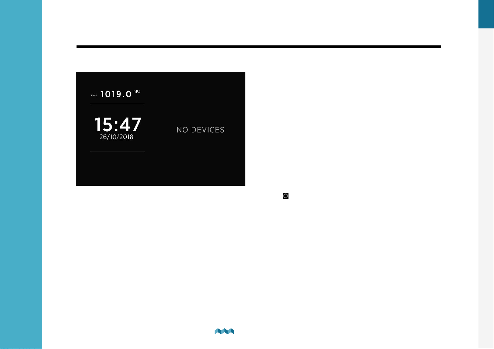
Start screen after first connection
After installation and first connection, you should see a screen similar to the one shown below.
After the first power-on, there are no batteries and tanks. Long press button to enter the settings menu.
24
Basic Setup
6.
Page 24

EN
6.5
Battery configuration
PICO shows all properly configured batteries. Each correctly configured battery will automatically show up on PICO. The
following section describes how to set up a battery on PICO.
6.5.1
In the settings menu navigate to DEVICES > BATTERY
Select “Add new” and fill in the requested data.
·
·
·
·
·
Adding a new battery
NAME - Name the battery/battery bank accordingly (STARTER, SERVICE, MAIN, etc.)
TYPE - Select the battery type (Wet low maintenance, Wet maintenance free, AGM, Deep cycle, Gel, LiFePO4)
C/20 - The declared capacity of your battery.
C/10 - Input only if the rating is explicitly provided by the manufacturer of your battery, otherwise leave it as “Not Set”.
C/5 – Input only if the rating is explicitly provided by the manufacturer of your battery, otherwise leave it as “Not Set”.
When configuring a battery bank, you have to input the ratings of the battery bank as a whole.
Example: if you have 3x 100Ah batteries connected in parallel, C20 = 3x 100Ah = 300Ah. The same rule applies for C10 and
C5 ratings.
For lithium batteries, only input C20 rating and keep C10 and C5 as “Not Set”.
·
VOLTMETER - Select a voltmeter connected to the battery. Only voltmeters that are not already used elsewhere in the
configuration are displayed on the screen.
Note: Do not select PICO Internal - as this is not a calibrated voltage reading.
25
Basic Setup
6.
Page 25

·
AMMETERS - Select the current sensor connected to the battery. You can select only current sensors that are not already
used by another battery configuration. For a battery configuration without a shunt (voltage-only), leave ammeters empty.
·
TEMPERATURE SENSOR- Select a temperature sensor if you have one installed and configured.
·
RANGE - Adjust the presentation of the current reading for the battery. By default the value is set 100A and it means, that
the bar used for visually representing the measured current will be displayed as full at 100A (the default range is between
0A - bar empty and 100A - bar full).
EN
·
INSTANCE - An identifier for NMEA2000 network. For use with NMEA2000 each battery has to have a unique instance
field. Confirm and save the bank configuration with button.
·
DELETE - With this option, you can delete the selected battery
26
Basic Setup
6.
Page 26
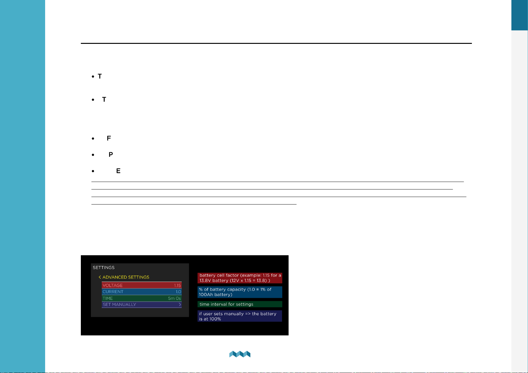
6.5.2 Advanced settings
Advanced users may adjust some additional battery settings to customize the battery data display. It is not suggested to
change these settings – the defaults should be suitable for all battery types.
·
TTG AVG – averaging interval for calculating TTG (time-to-go). “Short” means that TTG will respond to the change in
current more quickly, and “Very long” means that TTG will respond to the change in current more slowly.
·
TTG SOC MIN – Represents a declared offset from the actual battery state. Set by default to 20% means that when
PICO will display the remaining state of battery to be 0%, the actual state of the battery will be 20%. In case you want
to compare PICO readings to internal battery monitoring system provided by the battery manufacturer, it is important
to set this parameter to 0%, which will give you the absolute state of the battery.
·
CEF – charging efficiency (%).
·
DISPLAY TYPE – “Detailed” display type also shows the amp-hour counter on the batteries screen.
·
BATTERY FULL SETTINGS
Any changes under these settings may cause huge offsets in precision of monitoring your battery. These settings should
only be altered in extreme cases, such as if your battery is old and dying and can no longer hold the same amount of
charge that is declared by the battery manufacturer. In that case, you can alter these settings, so that PICO can correctly
determine when the charge in the battery reaches its full capacity.
-
Advanced users
EN
These settings are only relevant when the battery is monitored using a shunt (current + voltage).
Here, users may set additional battery full parameters, which will be used by PICO to help determine when the battery is full.
Example:
27
Basic Setup
6.
Page 27

- If you have a 13,8V 100Ah battery, then you can use the settings from the picture above.
- System voltage (12V) x factor (1.15) = 13,8V -> your battery full voltage.
- Battery capacity (100Ah) ....... 1.0 is a % factor of the battery capacity (1.0 = 1Ah = 1%).
- Time -> This setting is a determined time interval for how long both conditions (voltage, current) need to take place for
the battery to be determined as full (100%).
Set manually -> Use this calibrate the batteries state of charge to 100%. You should use this functionality only when the
battery is actually full. Once you select this option, the PICO will note the battery as full and after that it will rely on the
calculations based on the input/output current readings.
Execute the calibration when you are sure that the battery fullness is at 100%.
PICO uses an algorithm which tries to find the starting state of charge of the battery after the configuration. For
lithium batteries it is highly recommended, that you calibrate the battery manually after you configure it.
EN
28
Basic Setup
6.
Page 28
EN
6.6
Tank configuration
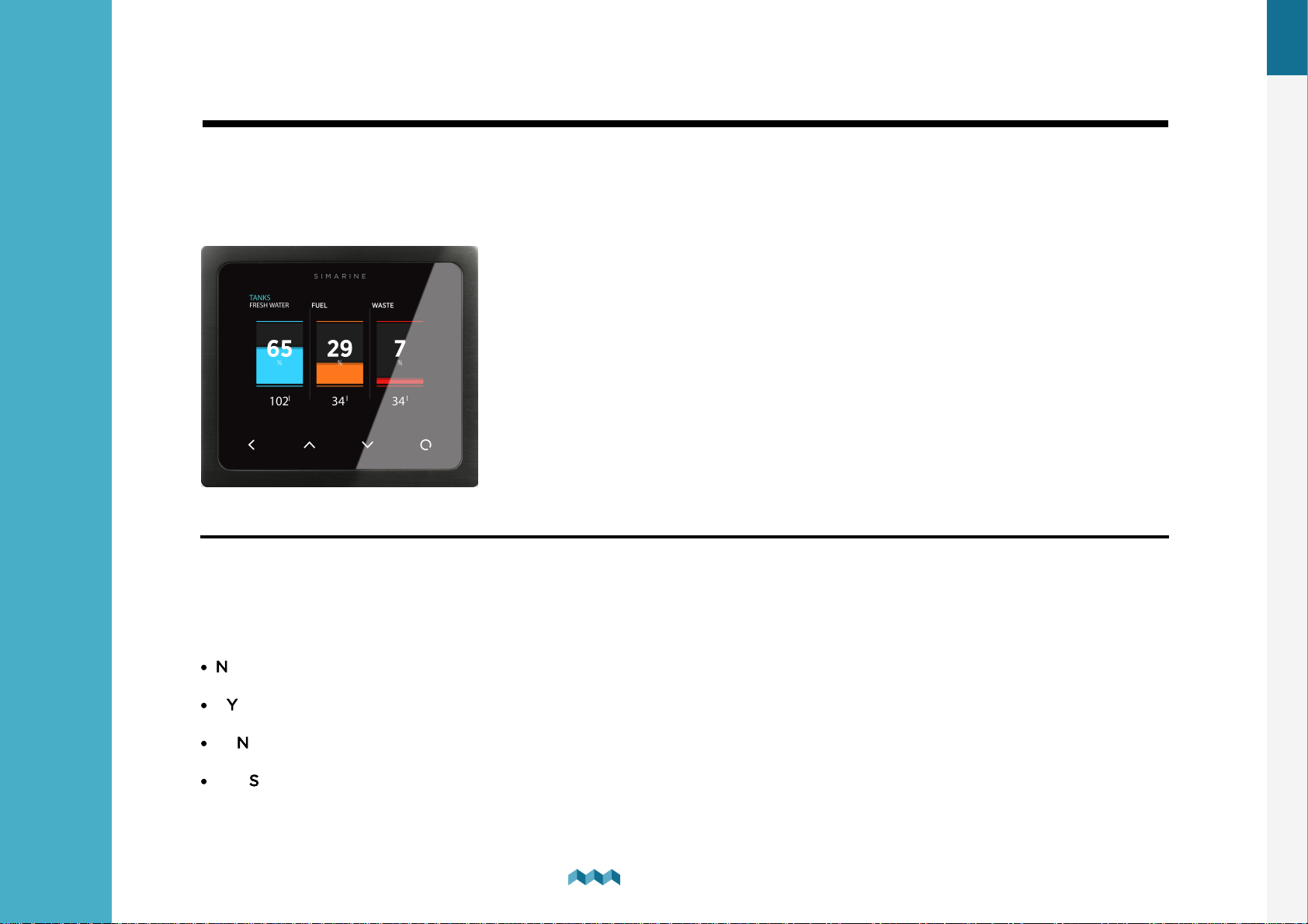
PICO shows all properly configured Tanks.
Each configured Tank will automatically show up on PICO. The following section describes how to set
up a tank on PICO.
Below is an example image of how the tank screen looks like on PICO.
6.6.1
Adding a new tank
After connecting a tank sensor to an appropriate module (ST107, SC303/503, SCQ25T) input, you can configure the tank by
following these steps:
In the settings menu, navigate to DEVICES > TANKS.
Select "Add new" and fill in the requested data:
·
NAME - Name the tank accordingly
·
TYPE - Select the tank type (WATER, FUEL, WASTEWATER), which defines the color of the tank on Pico’s screen.
·
SENSOR TYPE - Select the used sensor's type (RESISTANCE or VOLTAGE)
·
SENSOR - Select the used sensor input from the Only resistance/voltage inputs that are not already used elsewhere in the
configurations will be displayed on the screen.
29
Basic Setup
6.
Page 29
·
CAPACITY – Input the full tank capacity.
·
CALIBRATION POINTS – Add calibration points for different tank levels. For a proper configuration at least two
calibration points are required.
For square shaped tanks we suggest two calibration points (full and empty).
For irregular shaped tanks, we suggest you input a third (the middle) point. The rest will be calculated by PICO on the fly.
·
DISPLAY PRIORITY – Set the display priority of the tank (this is practical only when there are multiple tanks configured)
·
DISPLAY MODE
EN
- Standard – displays tank content in measuring unit and percentage.
- Fewer data - display tank content only in percentage
·
INSTANCE – An identifier for NMEA2000 network. For use with NMEA2000 each tank has to have a unique instance
field. Confirm and save the tank configuration with button.
The newly added tank should now be visible on one of the PICO’s screens, once you exit the settings menu (visible on the
main menu screen).
COMPATIBLE TANK SENSORS:
Any analog voltage/resistance type tank sensor, that is made for general use and not locked to a specific tank level monitor,
will work with the SIMARINE system.
The compatible ranges are:
Resistance: 0 Ohm - 65000 Ohm (65kOhm) or anything in between.
Voltage: 0.0V - 70.0V or anything in between.
30
Basic Setup
6.
Page 30

EN
6.7
·
·
·
·
·
Temperature sensor configuration
PICO shows all properly configured temperature sensors. Each correctly configured sensor will automatically show up on
PICO. The following section describes how to set up a sensor on PICO.
6.7.1
In the settings menu, navigate to DEVICES > TEMPERATURE SENSORS.
Select “Add new” and fill in the requested data.
Adding a temperature sensor
NAME – Name the temperature sensor
TYPE – Select the type of the sensor:
- NTC 10k (down to -13°C / 8.6°F)
- NTC 5k (down to -20°C / -4°F)
- NTC 1k (down to -40°C / -40°F)
DEVICE – Select the resistance input to which your temperature sensor is connected to.
DISPLAY PRIORITY – Set the display priority of the temperature sensor (this is practical only when there are multiple
temperature sensors configured)
RANGE (MIN / MAX) – Select the minimum and maximum temperature point displayed on the temperature graph.
·
CALIBRATION – Set the temperature offset if necessary.
·
SOURCE – Define the source of the temperature reading for use with NMEA2000 network.
·
INSTANCE – An identifier for NMEA2000 network. For use with NMEA2000 each temperature sensor has to have a
unique instance field.
6.8
Inclinometer configuration
PICO shows all properly configured inclinometers. Each correctly configured sensor will automatically show up on PICO. The
following section describes how to set up a sensor on PICO.
31
Basic Setup
6.
Page 31

6.8.1 Adding a new inclinometer
SIMARINE DIGITIAL INCLINOMETER MODULE DOES NOT REQUIRE ADDING A NEW INCLINOMETER OR INPUTTING
ANY SETTINGS, AS THAT WILL BE ADDED AUTOMATICALLY WHEN SD01-DIGITAL INCLINOMETER IS CONNECTED
TO THE SYSTEM (Plug&Play).
In case you are using some other analog inclinometer, you will have to configure it manually.
Although, when using the Digital Inclinometer, you do not have to configure any settings as it is Plug&Play device, you can
adapt some settings to your liking (relevant properties are marked with “**”).
In the settings menu, navigate to DEVICES > INCLINOMETERS.
Select “Add new” and fill in the requested data.
·
NAME ** - Select name of the inclinometer (PITCH / ROLL).
·
SENSOR – Select a voltage input to which you connected your analogue inclinometer to.
·
NONLINEAR ** - Enabling this property will make smaller angles to be presented in a non linear way, so that it is easier
for a user to see the measured angle presented with the lines on the inclinometer screen.
·
RANGE – Select the range on which the output range of your analogue inclinometer (0-5V / 0-10V)
EN
·
DISPLAY ** - You can toggle if the inclinometer is displayed on the inclinometer screen.
·
REVERSE ** - With this option you can reverse the inclinometer readings
·
DELETE - With this option, you can delete the selected inclinometer sensor.
6.9
User sensor configuration
PICO shows all properly configured user sensors. Each correctly configured user sensor will automatically show up on PICO.
The following section describes how to set up a sensor on PICO.
32
Basic Setup
6.
Page 32

6.9.1 Adding a new user sensor
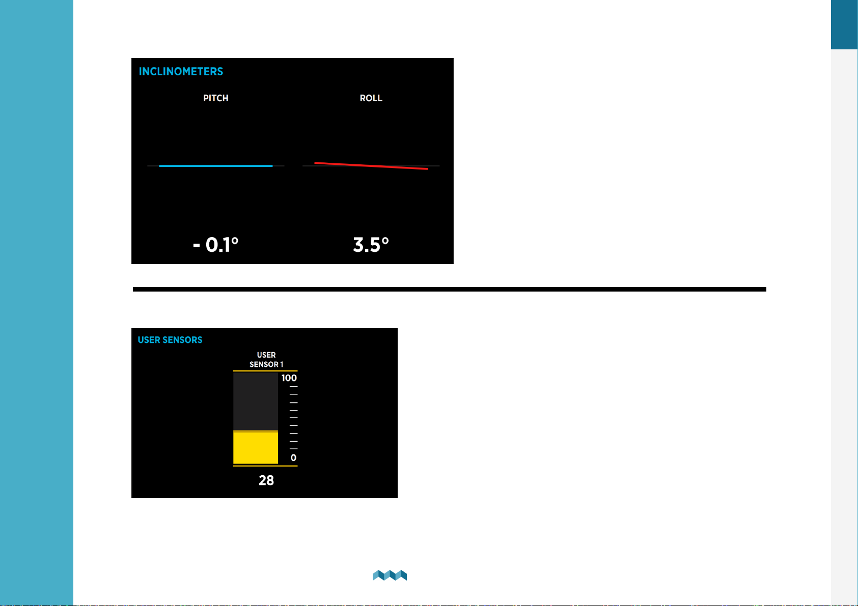
In the settings menu, navigate to DEVICES > USER SENSORS.
Select “Add new” and fill in the requested data.
·
NAME – Name the user sensor.
·
VOLTMETER – Select the voltage input used to measure the analog output of your voltage type user sensor.
·
LOW VALUE POINT – What value is presented by the LOW VOLTAGE POINT (see bellow).
·
HIGH VALUE POINT – What value is presented by the HIGH VOLTAGE POINT (see bellow).
·
RANGE (MIN/MAX) – Select the minimum and maximum point displayed on the graph of the user sensor.
·
DECIMALS – Set an offset of the decimal point (from right to left).
·
MEASUREMENT UNIT – Input the measurement unit that will be presented on the display graph.
·
LOW VOLTAGE POINT – Expected voltage when the sensor measures its lowest value.
EN
·
HIGH VOLTAGE POINT – Expected voltage when the sensor measures its highest value.
·
DELETE - With this option, you can delete the selected user sensor.
6.10
Current sensors configuration
6.10.1 Current sensors
List of all current sensors (shunts). Connected shunt modules are added to the list automatically. In this list, you can view
real time readings (amperes) for all connected current sensors. By selecting a certain sensor, you can view or change its
settings.
33
Basic Setup
6.
Page 33
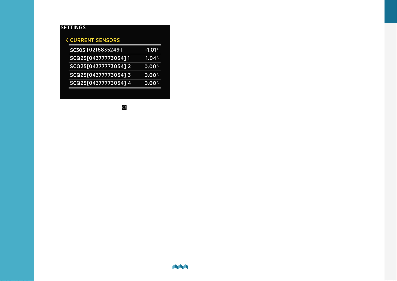
Pressing the enter button will open a settings screen for the selected sensor.
NAME - Assign a display name of the current sensor.
RANGE - Adjust the presentation of the current reading for the current sensor. By default the value is set 100A and it means,C
that the bar used for visually representing the measured current will be displayed as full at 100A (the default range is betweenC
0A - bar empty and 100A - bar full).
EN
REVERSE CURRENT - For consumers the current reading should be a negative number measured and for generators itC
should be a positive number measured and displayed on the CURRENT SENSORS screen. In case of reverse wiring, theC
situation might be exactly the opposite. This can be resolved either by rewiring the shunt or - easier - by toggling this option.
ADD CURRENT - Determines if the measured current should be used in the calculation of the state of charge for the batteryC
to which this shunt is assigned to.
In case there a multiple shunts in the system it is important to watch out for a possible "double current" problem (when
the same current is calculated twice). This happens if the same current passes through multiple shunts. Example: a fridge
is monitored individually with a dedicated current sensors, but the same current passes also through the main battery
shunt. In such case, we should configure the monitor so that it will calculate only the current of one of the sensors, while
the purpose of the other sensor is purely the convenience of the user to see the device's consumption (individual device
monitoring).
34
Basic Setup
6.
Page 34

BATTERY - Here you can assign your shunt to a battery. More common way is to assign shunts to a battery through the
battery configuration screen.
DISPLAY SEPARATELY - If enabled, the shunt will be displayed in separate screen, even if the shunt is assigned to a battery.
DISPLAY PRIORITY - Set the display priority of the current sensor. Here you can also hide the current sensor.
DEVICE - Displays a full ID of the current sensor. This is read only and it will not change even if you rename the sensor.
MERGE WITH - Gives you an option to merge the sensor with another sensor. That way you tell PICO to consider the
readings of two current sensors as a reading of a single device.
EN
35
Basic Setup
6.
Page 35

7
Screens
Page 36
7. Screens
!
PICO’s algorithm for calculating state-of-charge (SOC) is not
a simple Ah-counter. It is constantly monitoring battery current, voltage, and temperature. The data is
compared to the internal battery model, and its parameters are constantly being adjusted so that the model
fits the actual data. The algorithm needs some time to adjust the parameters, and it will improve accuracy
during the first few cycles.
You can switch between different screens by pressing the up or down arrow buttons. There will be a separate screen for
each battery with at least one connected current sensor (shunt). Multiple batteries without a current sensor (measuring
voltage only) may join on a single screen.
Up to four tanks and four thermometers will join on a single screen. If there are more, they will divide into two
or more screens. There is also a separate barograph screen on PICO.
EN
7.1
Batteries screen
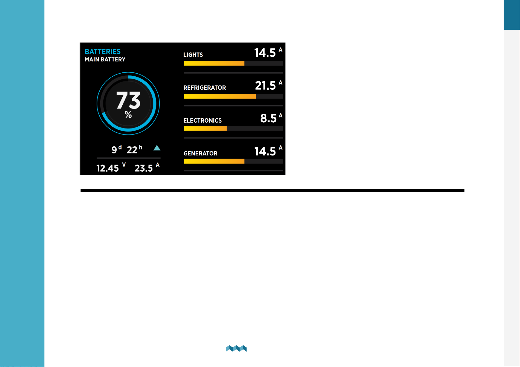
Screens for showing battery data differ depending on how many current sensors are connected to a certain battery. If the
battery connects only to a voltage sensor (without a current sensor), the battery name, approximate state-of-charge (SOC)
and current-voltage are displayed.
The calculation of SOC takes some time, so it may not be shown immediately after power-on.
Up to three batteries without a current sensor can be shown on a single screen. If there are more, they divide into two or
more screens.
If the battery is connected to a voltage sensor and a current sensor (shunt), some additional data is displayed: time to
charge/time to discharge, current (amps) and voltage.
Monitoring a battery with a shunt, gives you the highest possible precision. For lithium batteries using a shunt is
mandatory.
Time to discharge is calculated by using an average consumption during a period of time. If there is more than one current
sensor (shunt) connected to the battery (e.g., for monitoring different consumers or generators, connected to the battery),
their data (amps) is also shown on the battery page.
38
Screens
7.
Page 37
EN
7.2
Tanks screen
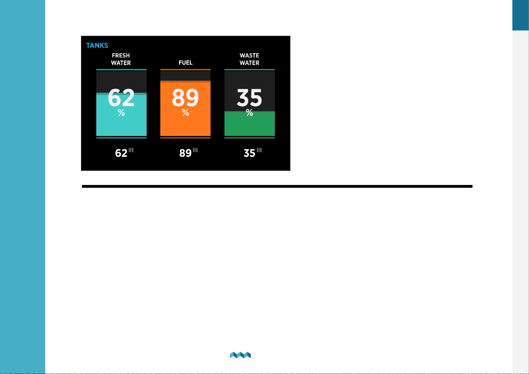
Tanks screen shows the current level of connected and properly configured tanks. Up to four tanks can be displayed on a
single screen. If there are more, they divide into two or more screens. For each tank, you can find its name, graphical
representation of the current level, and numerical values of the current level as a percentage and as the volume unit (liters,
gallons).
Depending on the selected tank types, they are represented with different colors.
If the tank sensor isn’t selected in the tank settings or the sensor got disconnected from the PICO system, the “OFFLINE”
symbol will appear on the screen. If this situation occurs, check the sensor setting of the tank.
If the sensor is selected, check if all the cables are properly connected.
39
Screens
7.
Page 38
EN
7.3
Temperatures screen
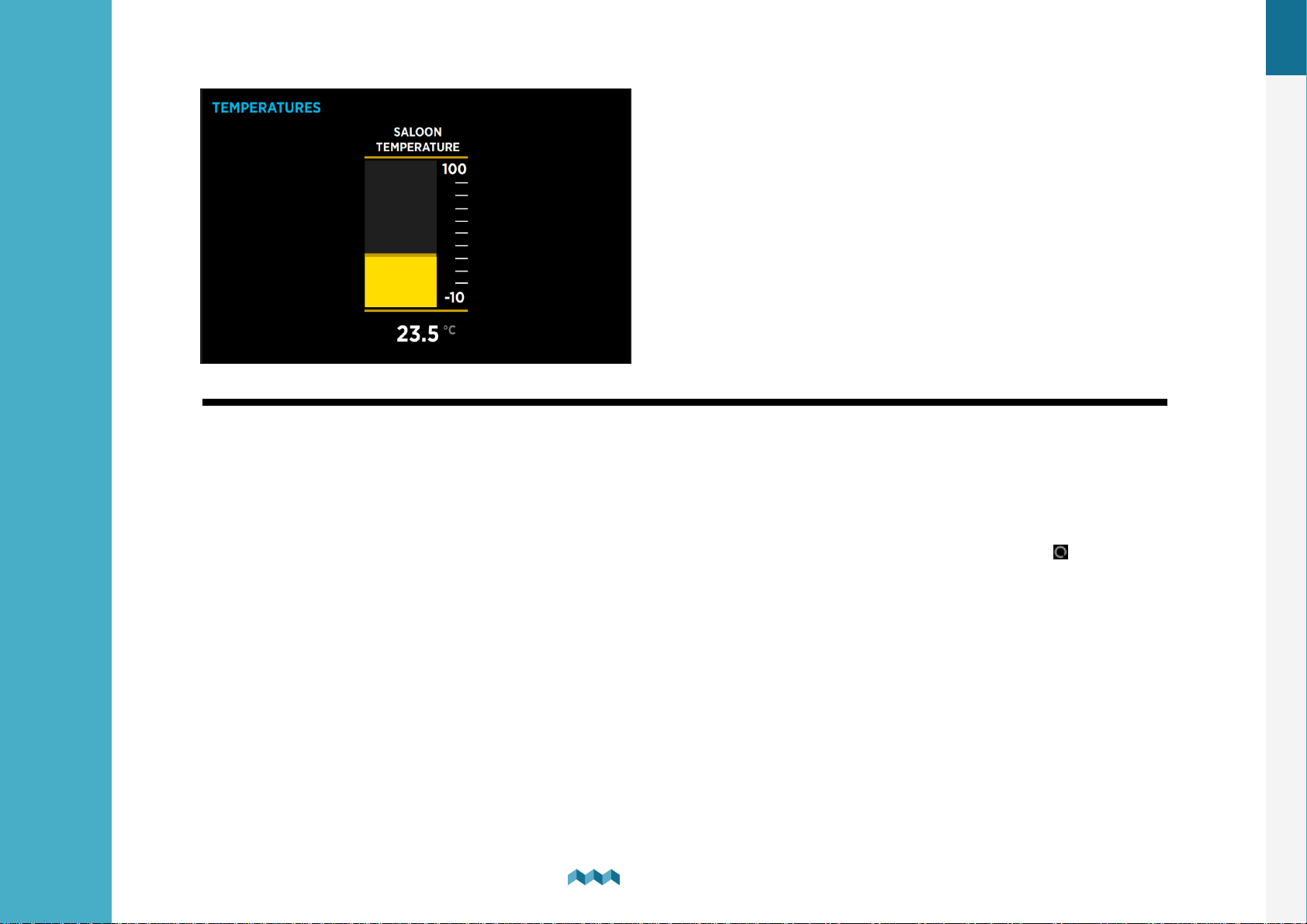
Temperatures screen shows current temperatures of connected and correctly configured temperature sensors.
Up to four temperature sensors can be shown on a single screen.
If there are more, they divide into two or more screens.
For each sensor, you can find its name, graphical representation of the current temperature, and the numerical value of the
current temperature in the chosen unit (°C or °F).
If the temperature sensor is not selected in the temperature sensor settings or the sensor is disconnected from the PICO
system, the “OFFLINE” symbol will appear. If this situation occurs, please check the temperature sensor setting. If a device is
selected, please check if all the cables are properly connected.
NOTE: In case your temperature is displayed as a constant -13°C (8.2°F) or some other high or low value, then the
most likely problem is that you do not have a correct sensor input selected. Selecting any sensor input to which no
temperature sensor is connected to, will result in such readings.
40
Screens
7.
Page 39
EN
7.4
Barograph screen
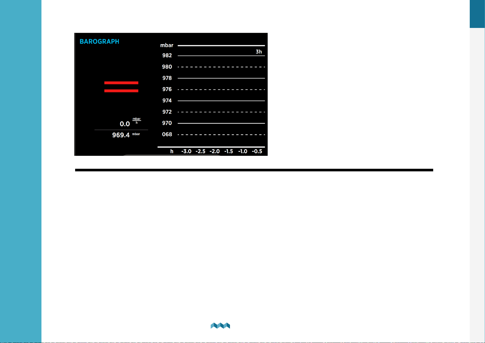
The symbol on the left shows the current air pressure trend. The arrow shows trend direction (up – rising or down – falling). If
the pressure is increasing or decreasing rapidly (1.0 mbar/h or more), two arrows are shown.
Below the trend symbol, two values show the current trend and current sea level pressure.
You can find the barograph on the right side.
The default interval for the barograph can be changed in the settings menu (BAROGRAPH > TIME INTERVAL). However,
you can also manually switch between different time intervals on the barograph screen by shortly pressing the button.
Screens
41
7.
Page 40
EN
7.5
Inclinometers screen
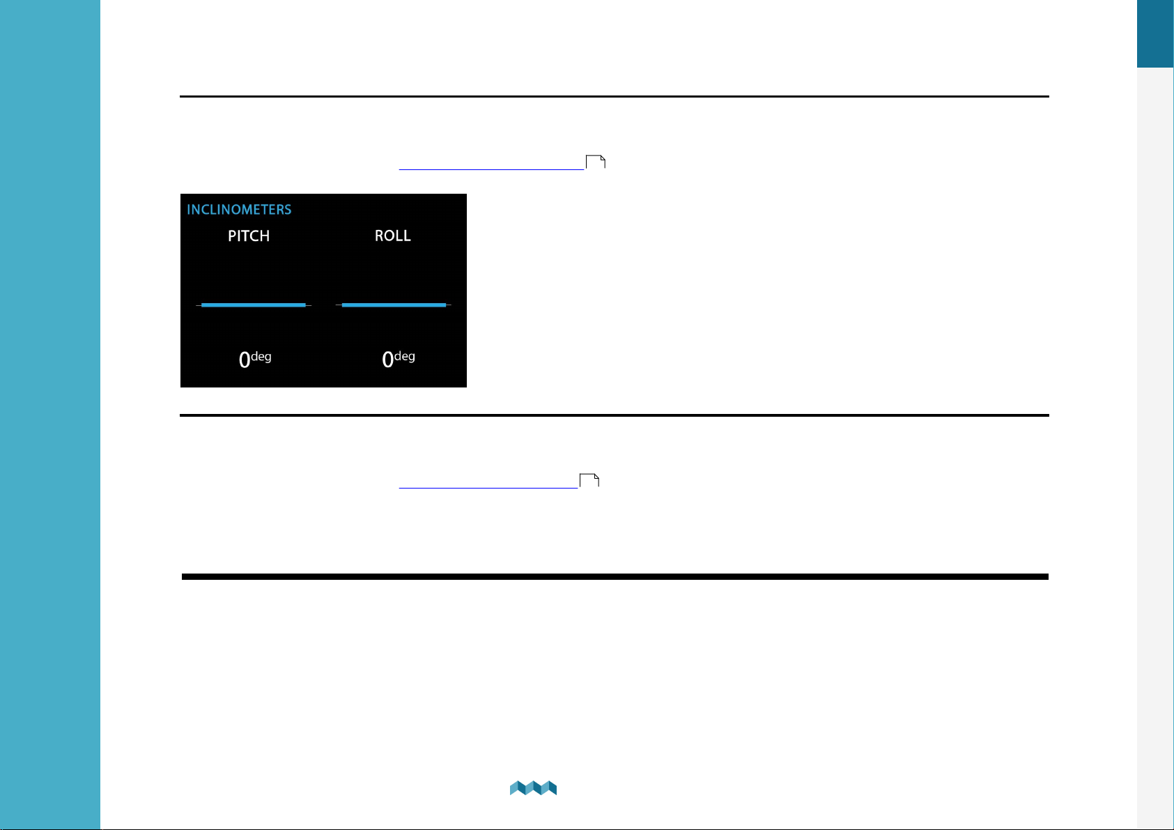
If you have an inclinometer installed, the “Inclinometers screen” shows your pitch and roll data.
Pitch is shown on the left side of the screen. The left side of the line represents the front of the vehicle or boat (bow), while
the right side of the line represents the back of the vehicle or boat (stern).
The pitch angle in degrees is shown below the line (positive value meaning front facing up and vice versa).
Roll is shown on the right side of the screen. The left side of the line represents the left-hand side of the vehicle or boat. The
roll angle in degrees is shown below the line (positive value meaning left-hand side up and vice versa).
42
Screens
7.
Page 41
EN
7.6
User Sensors Screen
Screens
7.
43
Page 42
EN
7.7
Alarms screen
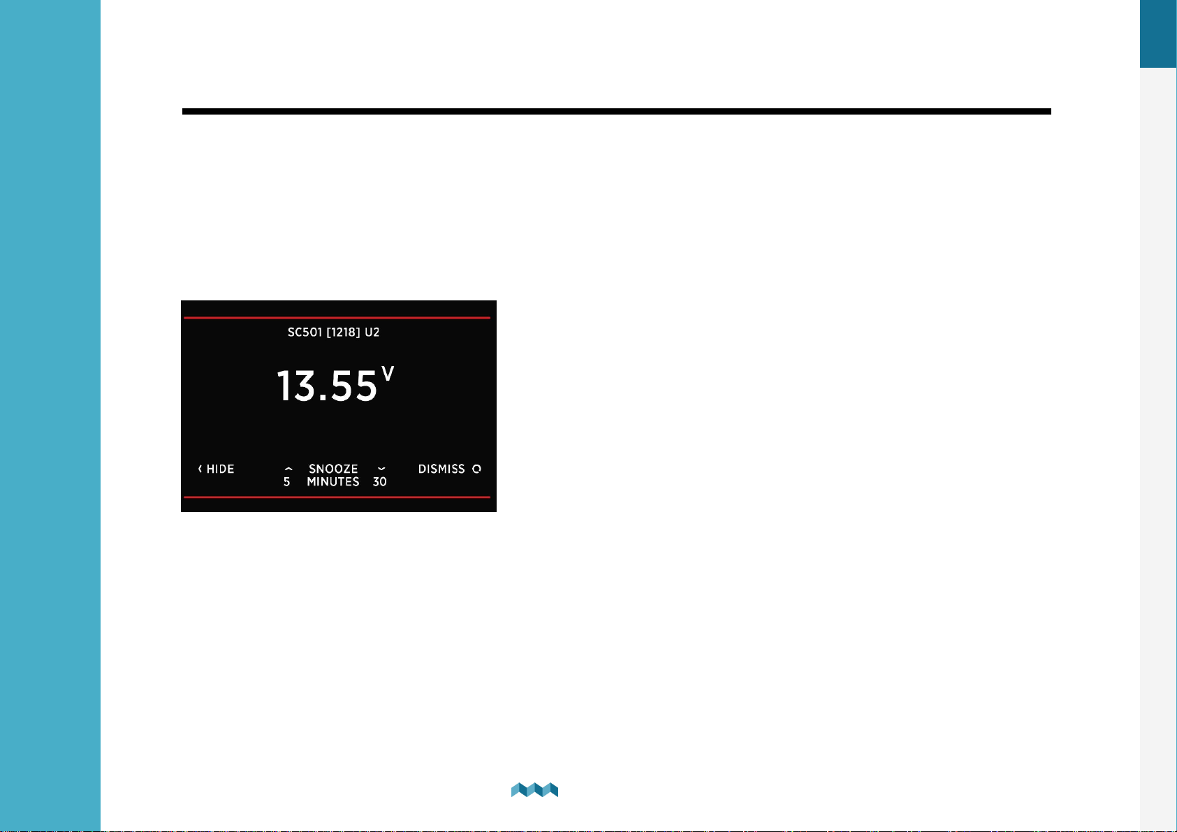
When an alarm is triggered it is shown on PICO (see image below). From there you can control the alarm state.
Hide, which hides the alarm from the display.
Snooze, for 5 or 30 minutes, which means it is hidden for 5 or 30 minutes and then displayed again if still active. The output is
active (if configured).
Dismiss, turns the alarm and output (if configured) off for 24 hours.
When multiple alarms are active, at the same time, then they are alternately
displayed.
If at least one alarm is active, then an alarm entry on top in the menu settings is displayed. From there you can view all
currently active alarms.
44
Screens
7.
Page 43

8
Device configuration
Page 44
8. Device configuration
You can enter the settings menu by long pressing the button.
EN
8.1
General settings
8.1.1 Screen
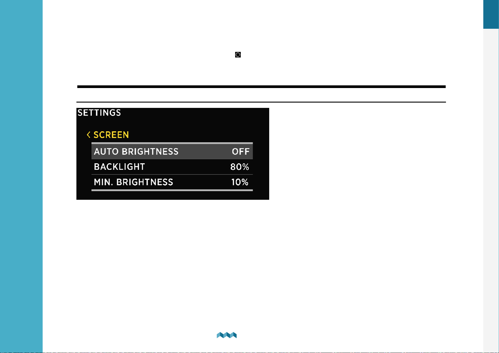
AUTO BRIGHTNESS - When auto-brightness is enabled, Pico’s internal light sensors automatically adjust the screen
brightness to match the ambient lighting conditions.
BRIGHTNESS - The brightness level used during normal operation. When AUTO BRIGHTNESS is enabled, this is the maximum
brightness level.
MIN. BRIGHTNESS- Min. brightness has two functions.
1. When PICO is in sleep mode, the illumination is set to min. brightness level.
2. When AUTO BRIGHTNESS is enabled, it defines the minimum illumination.
46
Device configuration
8.
Page 45
8.1.2 Device
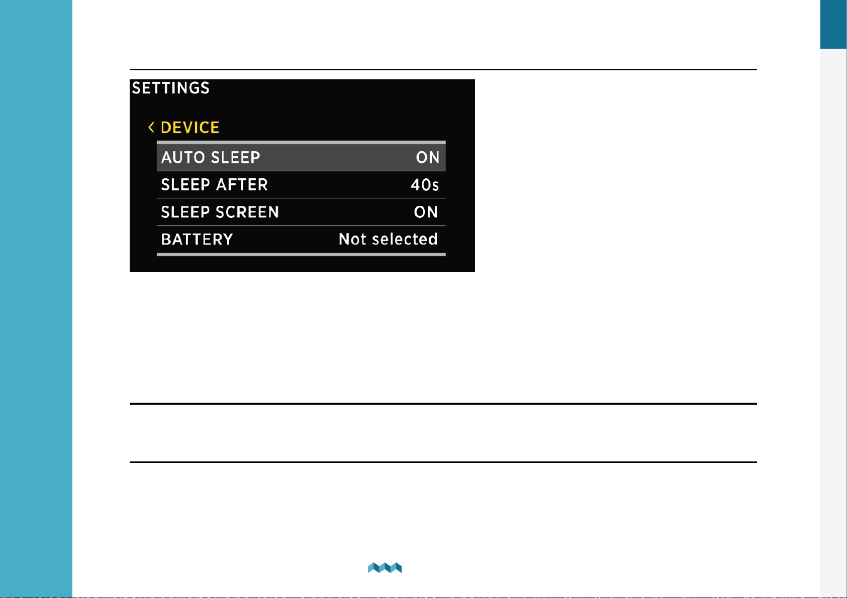
AUTO SLEEP - Enable/Disable auto sleep function.
SLEEP AFTER - Time after which PICO goes into sleep mode if the AUTO SLEEP setting is enabled.
SLEEP SCREEN - If SLEEP SCREEN is enabled PICO will display home screen when in SLEEP MODE.
BATTERY - This determines which battery will be displayed on the home screen.
POWER MANAGEMENT --> AUTO POWER OFF - Automatically powers off the PICO, if this is ON.
POWER MANAGEMENT --> AUTO POWER OFF DELAY - Automatically powers off the PICO after selected time.
EN
8.1.3 Language
You can choose between English, German, French, Spanish and Polish languages. More languages will be added with future
firmware upgrades.
8.1.4 Units
You can choose different international measurement units for pressure, temperature, volume, altitude and speed.
47
Device configuration
8.
Page 46

EN
8.2
Data management
This menu enables you to set up alarms for certain measurements. Here, you can choose the quantity, the device, low and
high values for alarm, and you can turn the high/ low-value alarms on and off.
·
ALARM LOW: Low-value alarm fires when the measured value is lower than the setup alarm value
·
ALARM HIGH: High-value alarm fires when the measured value is higher than the setup alarm value
After you select ALARM LOW or ALARM HIGH, the following alarm settings will appear:
·
ALARM STATE - enable and disable alarm.
·
ALARM VALUE - a limit value which fires the alarm.
·
SILENT, if enabled, there will be no audible signal when the alarm fires. The alarm warning will only appear on PICO’s
screen.
·
ALARM DELAY, the time delay with which the alarm is fired. The alarm fires when only the measured value is below (for
alarm low) or above (for alarm high) the “alarm value” during the delay period.
·
ALARM DURATION, the selected alarm duration. 5 minutes by default. Setting the duration to 0 seconds will keep the
alarm active until manually dissmised.
·
OUTPUT - the digital output that is turned on during an active alarm.
.
.
·
OUTPUT MODE -
·
ON / OFF - It will toggle the alarm ON/OFF depending on the alarm value.
·
ON - It will toggle the alarm ON when the alarm value is reached.
It will not turn OFF when the conditions are no longer met.
·
OFF - It will toggle the alarm OFF when the alarm value is reached.
It will not turn ON when the conditions are no longer met.
·
OUTPUT DELAY - Time delay of firing the alarm output after the alarm conditions are met.
48
Device configuration
8.
Page 47

EN
8.3
Devices
Here, you can manage all the devices that are connected to your PICO. When you connect a new module to your PICO
system (e.g., a new shunt), some new devices will automatically appear on the devices list (e.g., current sensors, voltmeters,
ohmmeters…). These devices automatically appear because they are integrated into the modules. But “secondary” devices those that are connected to the modules (BATTERIES, TANKS, THERMOMETERS, and analog INCLINOMETERS) - will not be
added automatically. If you connect a new battery, tank or thermometer, you have to add and configure the new device
manually in the DEVICES menu.
Devices are grouped into different device types. To view, manage, add or delete a certain device, please select the
corresponding device type from the list (e.g., BATTERIES, TANKS …).
8.3.1
List of batteries which you have added to your PICO. By selecting a certain battery, you can view or change its settings, and
you can delete the battery if you need to. By selecting “Add new” you can add a new battery.
For more information go to the Adding a new battery .
If the battery connects only to a voltage sensor (without a current sensor), the battery name, approximate state-of-charge
(SOC) and current-voltage are displayed. The calculation of SOC takes some time, so it may not be shown immediately
after power-on.
Up to three batteries without a current sensor can be shown on a single screen. If there are more, they divide into two or
more screens.
Batteries
25
If the battery is connected to a voltage sensor and a single current sensor (shunt), some additional data are displayed:
time to charge, time to discharge and electrical current (amps). SOC can be calculated more accurately if a current sensor
is connected. Time to discharge is calculated by using an average consumption during some period.
If there is more than one current sensor (shunt) connected to the battery (e.g., for monitoring different consumers or
generators, connected to the battery), their data (amps) is also shown on the battery page.
49
Device configuration
8.
Page 48
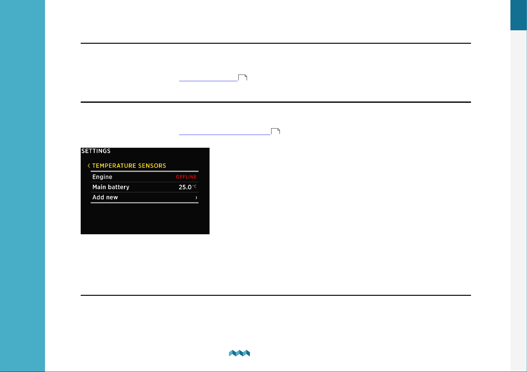
8.3.2 Tanks
List of tanks which you have added to your PICO. By selecting a certain tank, you can view or change its settings, and you
can delete the tank if you need to.
By selecting “Add new” you can add a new tank.
For more information go to the Adding a new tank .
29
EN
8.3.3
List of temperature sensors which you have added to your PICO. By selecting a certain sensor, you can view or change its
settings, and you can delete it if you need to. By selecting “Add new” you can add a new temperature sensor.
For more information go to the Adding a temperature sensor .
Temperature sensors
31
8.3.4 Coulomb counter
For each connected current sensor, a corresponding Coulomb counter will also appear on the devices list. Each Coulomb
counter shows a total electric charge (in Ah, amp hours) that has transferred through this sensor until now. By selecting
a certain Coulomb counter, you can manually reset the counter to zero.
50
Device configuration
8.
Page 49
8.3.5 Inclinometer
List of inclinometer sensors which you have added to your PICO. By selecting a certain sensor, you can view or change its
settings, and you can delete it if you need to. By selecting “Add new” you can add a new analog sensor with voltage output.
For more information go to the Adding a new inclinometer .
32
8.3.6 User sensors
EN
List of custom sensor which you have added to your PICO. By selecting a certain sensor, you can view or change its settings,
and you can delete the sensor if you need to. By selecting “Add new” you can add a custom user sensor.
For more information go to the Adding a new user sensor .
8.4
WI-FI
This menu offers all the Wi-Fi settings for your PICO.
OPERATION - When set to ON, Wi-Fi module is enabled. Otherwise, it is disabled, and no configuration data is displayed.
MODE - The PICO supports AP mode which stands for the access point and STA mode for station mode.
33
51
Device configuration
8.
Page 50
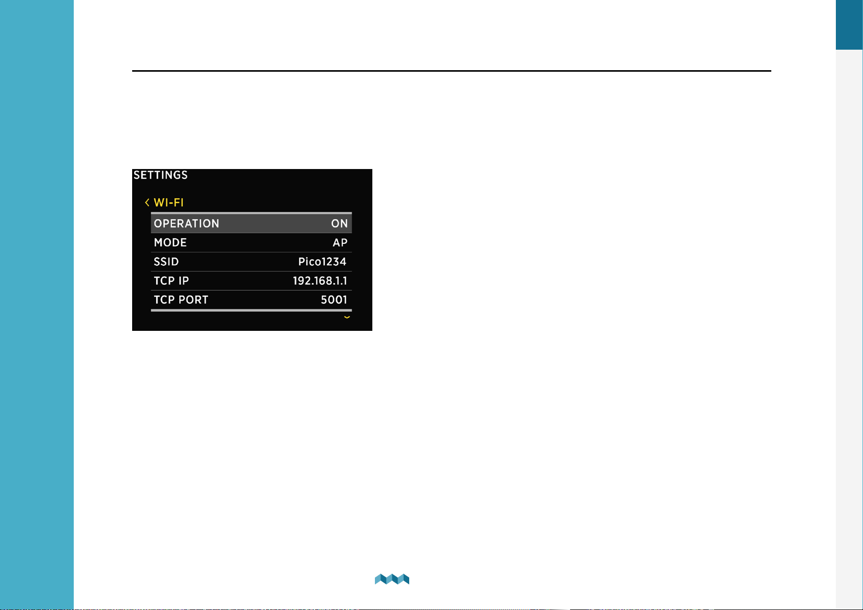
8.4.1 AP Mode
When in AP mode, the PICO creates its wireless network. If you want to connect to PICO with your smartphone, please
connect to the network whose name corresponds to SSID setting value. Wireless network password can be changed with
PASSWORD setting.
Example: if your PICO’s serial number is 12345678, then the default Wi-Fi SSID is pico5678 and the password is
pico1234.
EN
SSID - SSID stands for Service Set Identifier. In AP Mode, it is the Wi-Fi network name that is created by PICO.
TCP IP - Shows the default IP of your PICO.
TCP PORT - Shows the default TCP port for communicating with the PICO.
UDP IP - Shows the default IP to which UDP live data packets are sent.
UDP PORT - Shows the default UDP port for communicating with your PICO.
PASSWORD - Default password: pico<first four digits of the serial number>
WIFI RESET - This option restarts the WIFI settings for your PICO.
52
Device configuration
8.
Page 51

8.4.2 STA Mode
When in STA mode, you can connect PICO to your local router and connect with your smartphone via a router. This mode
enables more than one mobile app connecting to PICO at the same time.
To set up STA mode take the following steps:
·
Under MODE select STA mode.
·
Under SSID find and select your router.
·
PICO detects the security type, select password, and type in the WIFI password.
·
After this select connect and wait for PICO to connect.
EN
If the PICO can’t find your router SSID, check if SSID broadcasting is enabled on your router.
!
The Dynamic Host Configuration Protocol (DHCP) should be enabled on the router to assign an IP address dynamically.
!
53
Device configuration
8.
Page 52

EN
8.5
Date and time
In this menu, you can set the time, date, and time zone manually, but we do not recommend to do it, because these values
will be overridden by your smartphone settings each time you connect the phone to your PICO and start the Simarine
application*.
The exact time is important for the proper functioning of the device, and hence it is synchronized with your phone on each
connection.
However, time format and date format settings can be changed freely as your phone settings will not override these.
TIME - Set the current time*.
DATE - Set the current date*.
TIME ZONE - Set the current time zone*.
TIME FORMAT - You can choose your desired time format from the list.
DATE FORMAT - You can choose your desired date format from the list.
54
Device configuration
8.
Page 53

EN
8.6
8.7
System
Under the SYSTEM section you can find the following information:
COMMUNICATION DEVICES - List of all the devices (modules) that are connected to the PICO, together with the
bus communication quality (%).
SYSTEM INFO - Displays PICO’s serial number, currently installed firmware version and free memory.
Service
Under this section you can find information about the following:
SETTINGS LOCKED - Here, you can lock the settings of the PICO. A PIN will be required to unlock the settings in the future.
To lock the settings of the PICO, select ON, to keep the settings unlocked, select OFF.
MAIN SCREEN - Change what will be displayed on the main screen.
DEBUG SCREEN - Opens the debug menu, listing all the services and displaying whether the service is running (1) or not (0).
SYSTEM RESET - Deletes all the devices from the PICO. When clicked on, it will demand a PIN code, the code 1 2 3 4 1 2,
after that you can factory reset the PICO with long pressing the button.
55
Device configuration
8.
Page 54

9
Mobile application
Page 55
9. Mobile application
Your smartphone can remotely control PICO via Wi-Fi connection. Using the app, you can monitor current (live) data for
batteries, tanks and thermometers. You can also change the PICO settings on your smartphone, and upgrade Simarine
firmware to the latest version.
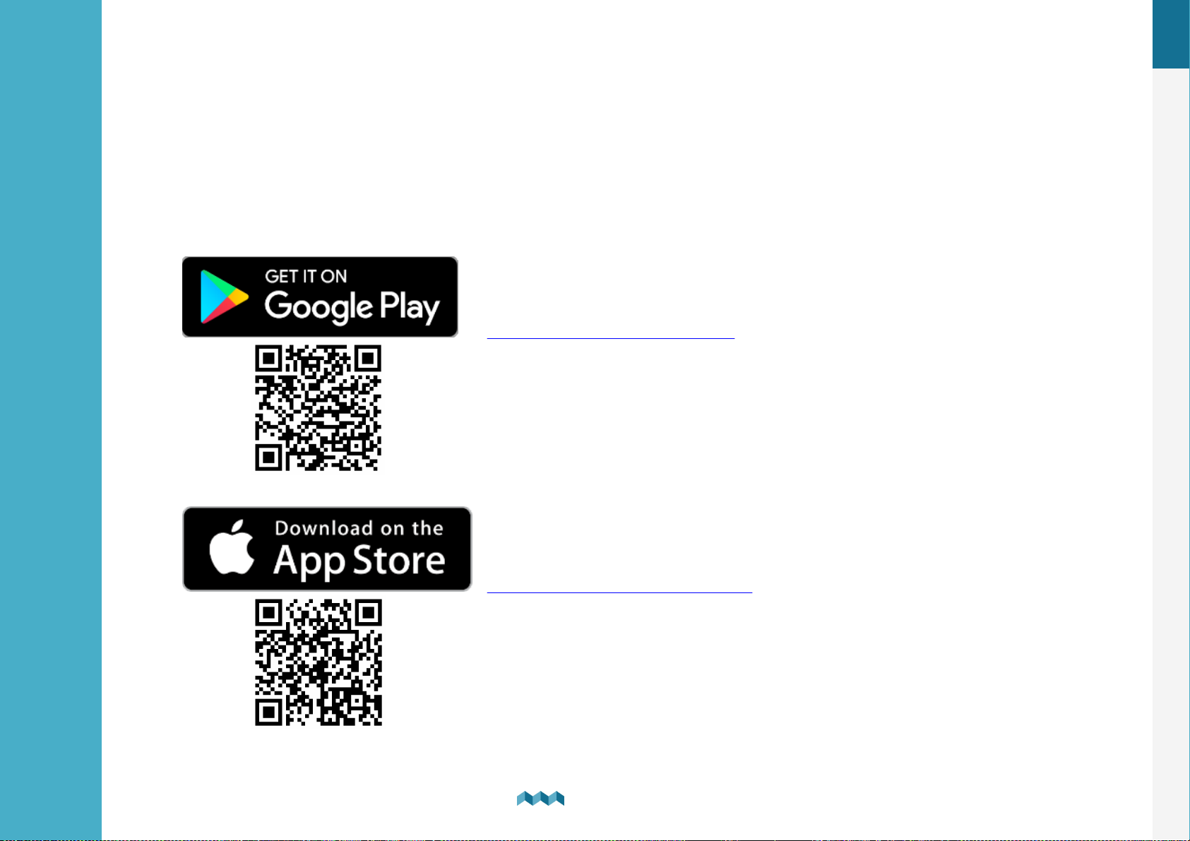
Find your Simarine – application in your mobile store by scanning the QR code below or visiting below link for your app
store.
Simarine App on Google Play
EN
Simarine App on the App Store
58
Mobile application
9.
Page 56

10
Save and restore settings
Page 57

10. Save and restore settings
!
You can restore to your previously saved settings if your PICO's physical configuration has not been changed (no shunts or modules have
been added or removed). If your PICO's physical configuration has changed, you will not be able to restore to the settings that had been
saved before the configuration has changed.
Before executing SYSTEM RESTORE make sure you do a SYSTEM RESET - which will erase any existing configurations.
Using your mobile app, you can save your current PICO settings to your phone, and you can restore your saved settings from
your phone to your PICO.
Save settings. To save settings, open your PICO mobile app and connect to your PICO. In the SETTINGS menu, choose
SAVE / RESTORE SETTINGS > SAVE CURRENT SETTINGS. Name your settings and tap OK. Your settings are then
saved.
Restore settings. If you want to restore your PICO settings, open your PICO mobile app and connect to your PICO via WiFi. In the SETTINGS menu, choose SAVE / RESTORE SETTINGS > RESTORE SETTINGS. A list of saved settings will
appear, together with a date and time when these settings saved. Select a desired record from the list and tap RESTORE.
You will be asked to confirm your action. After pressing RESTORE once again, wait a few seconds for your settings to
restore.
EN
If you use the same PICO physical configuration (the same number of modules and shunts) on multiple PICO monitors, it is
also possible to transfer the settings from one to another by using the same procedure.
60
Save and restore settings
10
Page 58

11
Firmware upgrade
Page 59

11. Firmware upgrade
!
It is important to install the latest Simarine Application (or to update your installed application to the latest version) before proceeding
with the firmware upgrade
To ensure the best PICO experience, we recommend upgrading the firmware to the latest version. You can do this via
Simarine application, available on your smartphone application market as described in chapter Mobile application .
The upgrade process requires the following steps:
1. Install or update the Simarine application on your smartphone.
2. Turn on Wi-Fi on your PICO.
3. Connect your smartphone to PICO via Wi-Fi.
4. Launch the phone application.
5. Go to the settings menu and tap > DEVICE SETTINGS > FIRMWARE UPGRADE and confirm the upgrade.
6. The upgrade process will put your PICO device in the upgrade mode.
7. Long press the button on your PICO to confirm the firmware upgrade. The upgrade process can take a few minutes
to complete.
8. After the upgrade, PICO reboots and is ready to use.
58
EN
If there is no FIRMWARE UPGRADE option in the application menu (step 5), please make sure that you have updated your
App to the latest version.
Emergency mode firmware upgrade procedure:
1. Turn PICO OFF and back ON again (may require toggling power to the PICO, see note bellow)*.
2. As soon as the start-up logo appears press and hold the left arrow key until PICO enters in text-only mode.
3. Connect your smartphone to PICO via Wi-Fi. A blue line of text will appear on PICO as soon as the connection is
established.
4. Lunch the phone application.
5. Wait for a red button labeled "FIRMWARE UPGRADE" to appear and press it.
6. Confirm the upgrade if prompted by the application.
7. After the upgrade, PICO reboots and is ready to use.
62
Firmware upgrade
11
Page 60

12
Technical specifications
Page 61

12. Technical specifications
PICO BATTERY MONITOR
Operating
Power source voltage range
6 - 35 V
Temparature range
-20°C to +70°C (-4°F TO +158°F)
Power consumption at 12 V
Operating, WiFi On, 100% illumination
90 mA
Operating, WiFi Off, 70% illumination
35 mA
Operating, WiFi Off, 0% illumination
18 mA
Power Off, logger still active
5 mA
Display capabilities
Current
Range
-999.99 to +999.99A
Resolution
0,01 A
Voltage
Range
0 - 75 V DC
Resolution
0,001 V
Amp hours (Ah)
±0,1 Ah
Temperature
Range
-40°C to + 150°C
Resolution
0,1 °C / °F
SOC - State of Charge
0 - 100%
EN
Technical specifications
12
64
Page 62

EN
WIFI
Radio Frequency Band
2,4 GHz
Monitoring capabilities
Up to
Batteries
6
Shunts
24
Temperature sensors
10
Tank level sensors
14
Inclinometer sensors
2
Dimensions (without connector)
PICO
157.10 x 82.10 x 5.60 mm
6.18 x 3.23 x 0.22 in
Technical specifications
12
65
Page 63

Safe Voyage.
 Loading...