

Page 1

USER AND
INSTALLATION MANUAL
MANUALE D’USO E
INSTALLAZIONE
GEBRAUCHS-UND
INSTALLATIONSANLEITUNG
MANUAL DE USO E
INSTALACIÓN
VIDEO PROJECTOR
PROJECTOR
SVD 800 HD
Page 2

SVD 800 HD
INDEX
1- WARNINGS
1.1 Safety and Regulations
2- GENERAL INFORMATION
2.1 Projector identification
2.2 Power cabling
2.3 Servicing
2.4 Spare parts
2.5 Cleaning the projector
2.6 Cathode-ray tube phosphor burning
2.7 Packing the projector
2.8 Room lighting
2.9 Back panel
3- USER REMOTE CONTROL RC 3100
3.1 Batteries
3.2 RC 3100 User Remote Control
3.3 Projector Power On
3.4 Input selection
3.5 Picture adjustment
3.6 Screen format selection
3.7 VCR button (Sync filter)
3.8 Information (INFO)
3.9 Muting video button
3.10 Normalised button
3.11 UPC button
3.12 Freeze button
3.13 Video Menu
3.14 UPC converter
3.15 Input Settings
3.16 Blanking
3.17 EHT NOISE RED
3.18 WHITE MENU
3.19 OPTIONS
3.20 Working time
3.21 OSD OPTIONS
3.22 LOGO
3.23 Installation menu
3.24 How to enter the SERVICE MODE
.........................................................................................
.............................................................
.................................................................
...............................................................
............................................................................
...................................................................................
................................................................................
...............................................................
................................................................
............................................................................
................................................................................
....................................................................................
...................................................................
...........................................................................
....................................................................
............................................................
............................................................
....................................................................
...................................................................
.....................................................................
................................................................................
............................................................................
...............................................................................
...........................................................................
............................................................................
....................................................................................
......................................................................
...........................................................................
..................................................................................
.............................................................................
.........................................................................
........................................................................................
.......................................................................
.........................................
................................................
.................................................
...........................................
Page 3
10
10
10
10
10
10
10
11
11
12
12
12
13
13
14
14
15
15
15
ENGLISHENGLISH
ENGLISHENGLISH
ENGLISH
4
4
4
5
5
5
5
6
6
6
6
8
9
9
9
9
9
4- INSTALLATION
4.1 Installation procedure
4.2 Removing the cover
4.2.1 Removing the top cover
4.2.2 Removing the front panel
4.3.1 Installation choice
4.3.2 Desk-top front projection
4.3.3 Desktop rear projection
4.3.4 Ceiling front projection
4.3.5 Ceiling rear projection
4.4 Projection angle measurement
4.5 Spacers
4.5.1 Spacer changing
4.5.2 Spacer table
4.6 Projector centering
4.7 Optical and electrical adjustments
...................................................................................
..................................................................
......................................................................
.....................................................................................
.......................................................................
..............................................................................
....................................................................
................................................................
............................................................
..........................................................
...........................................................
.............................................................
..............................................................
...............................................................
.................................................
............................................
1
16
16
16
16
17
17
17
18
18
20
20
20
20
21
23
23
Page 3

SVD 800 HD
4.8 Lens focus adjustment
4.9 Mechanical centering of the tubes
4.10 Correct screen viewing (deflections inversion)
4.11 Convergence adjustment
5- THE COMPLETE FUNCTION RC3000 REMOTE CONTROL
5.1 Complete function RC3000 remote control
5.2 Batteries
5.3 How the RC 3000 remote control works
5.4 Projector power on
5.5 Picture adjustment
5.6 Test patterns
5.7 White balance
5.8 MEMORY MANAGER
5.8.1 How to enter the memory manager
5.8.2 How to insert a label
5.8.3 How to change an aspect ratio (F)
5.8.4 Horizontal and vertical frequencies
5.8.5 How to store a new input signal
5.8.6 LOAD
5.8.7 COPY
5.8.8 MOVE
5.8.9 DELETE (DEL)
5.9 Installation types
5.10 Fine picture adjustments
5.11 Convergence (CONV)
5.11.1PHASE
5.11.2SHIFT
5.11.3LINEARITY
5.11.4Picture dimensions (SIZE)
5.11.5SKEW
5.11.6BOW
5.11.7KEYSTONE
5.11.8PINCUSHION
5.11.9ZONE
5.12 How to reset the adjustments (RESET)
5.13 How to store the convergence adjustments (MEMO)
....................................................................................
..............................................................................
...........................................................................
........................................................................................
........................................................................................
........................................................................................
..........................................................................
......................................................................................
........................................................................................
................................................................................
........................................................................................
..........................................................................................
...............................................................................
............................................................................
........................................................................................
..............................................................
............................................
..........................
..........................................................
...............................
...................................
....................................................................
....................................................................
...............................................................
...........................................
..................................................................
............................................
...........................................
................................................
.......................................................................
...........................................................
...............................................................
........................................................
....................................
...............
...........
Page 23
24
24
24
25
25
26
26
26
26
27
28
28
29
29
29
30
30
30
31
31
32
32
32
32
32
33
33
33
33
34
34
34
34
35
35
6- TECHNICAL SPECIFICATIONS
7- DISPLAY PERFORMANCE
8- ELECTRICAL DATA
9- MECHANICAL DATA
10- TEMPERATURE AND HUMIDITY RANGE
11- OPTIONAL ACCESSORIES
12- ST ANDARD ACCESSORIES
13- PIN ASSIGNMENT
14- TROUBLESHOOTING
15- FRENCH INSTRUCTION
16- GERMAN INSTRUCTIONS
...........................................................................
..........................................................................
..............................................................................
........................................................................
....................................................................
.........................................................
................................................................
...............................................................
.............................................................
................................................................
2
........................................
36
37
38
38
38
38
38
39
40
41
42
Page 4

SVD 800 HD
1 - WARNINGS
CAUTION
ELECTRIC SHOCK HAZARD
DO NOT OPEN
TO REDUCE THE RISK OF ELECTRIC SHOCK, DISCONNECT THE POWER
SUPPLY CABLE BEFORE OPENING THE EQUIPMENT
There are no parts inside the projector that need adjusting by
the user.
!
ENGLISHENGLISH
ENGLISHENGLISH
ENGLISH
Qualified technicians must be called to perform extraordinary
maintenance and adjustments.
This equipment has been tested and found to comply with the limits for a Class B digital device, pursuant to Part 15 of
the FCC Rules. These limits are designed to provide reasonable protection against harmful interference in a residential
installation. This equipment generates, uses and can radiate radio frequency energy and, if not installed and used in
accordance with the instructions, may cause harmful interference to radio communication. However, there is no
guarantee that interference will not occur in a particular installation. If this equipment does cause harmful interference
to radio or television reception, which can be determined by turning the equipment off and on, the user is encouraged
to try to correct the interference by one or more of the following measures:
- Reorient or relocate the receiving antenna.
- Increase the separation between the equipment and receiver.
- Connect the equipment into an outlet on a circuit different from that to which the receiver is connected.
- Consult the dealer or an experienced radio/TV technician for help.
Attention:
Before using this projector please read this manual through carefully and completely. This manual will provide you
with the basic instructions for using the projector. Installation, preliminary adjustments and procedures which require
the opening of the projector and contact with electrical components should be performed by qualified personnel. For
continued safe and reliable operation, use only power cables supplied by the manufacturer. Adhere to all notes and
warnings.
3
Page 5

SVD 800 HD
MAINS POWER
Mains power: 120-240Vac 48-62Hz +6%-10%
Max absorbed current: 4.2A
1.1 Safety and Regulations
A) Safety - conform to:
EN60950:
Equipment for information technology including electric
office equipment.
Safety.
German Law (RoV) -1987:
X-ray emission
USA Code of Federal Regulations: Title 21(21CFR)
X-ray emission
B) Electromagnetic Compatibility - conform to:
EN 50082-1:
Generic immunity law.
EN 61000-3-2:
Limits for harmonic current emission
2.1 Projector identification
The model and serial number are located on the
projector’s rear label
Record the serial number in the space below and quote it
each time you ask for information or technical assistance
from SIM2 Multimedia SPA.
Fig. 1
IM
PUTS
INFO
-
+
.
XXXXXXXXX
Fig. 1
EN 55022:
Limits and measuring methods of radio disturbance
produced by information technology equipment.
EN 61000-3-3:
Limits - Section 3 Limitation of Voltage Fluctuation and
Flicker in Low Voltage Supply Systems for Equipment
with Rated Current SYMBOL 163\f “Symbol” 16A.
•Warning
SIM 2 Multimedia S.P.A declines all responsibility
for damages to things and/or people caused by
incorrect mechanical or electrical installation of the
projector.
2 General information
The instructions detailed in this manual for the
installation and normal operation of the project must
be followed precisely.
Installation and preliminary adjustments must be
performed by qualified service technicians.
Mod. ...................... Serial number...............................
Before operating the projector, read carefully the
safety labels on the rear panel.
The lightning flash symbol on the label and the 33.5Kv
indication are intended to advise the user that inside the
projector there are components that can produce electric
shock.
Warnings:
To avoid damages, fire or electric shocks do not
expose this projector to the rain or damp. Qualified
service personnel should service and adjust the
projector’s internal parts.
- Never put objects of any kind through the projector’s
ventilation slots as they might touch high voltage
components or cause short circuits that could be a fire
or electric shock hazard.
- Do not spill any liquid spill on the projector.
- If an object or liquid manages to get inside the projector,
unplug it immediately and call for the assistance of
qualified personnel.
- Do not attempt to use it as it could be dangerous or
even worsen the damage.
4
Page 6

SVD 800 HD
LINE INPUT
• VEDE
- If the projector is not used for long periods of time or
during storms, unplug the projector temporarily from the
mains to avoid damaging the projector caused by
lightning or temporary overcurrents.
- Do not stand the projector on unstable surfaces as it
could drop causing serious damage.
- The projector has slots for ventilating the internal
components - do not cover or block them.
- The projector should always be put on a solid, firm
surface.
- The projector should not be made part of a fitted
installation or closed unless there is sufficient ventilation.
- After technical assistance or repairs on the projector
have been completed, ask the technician to carry out a
safety check (all cables and components in the right
position) and to make sure the projector is in proper
operating conditions.
2.2 Power cabling
The projector’s mains power device is shown in the picture
Fig. 2
.
2.3 Servicing
Servicing must be carried out by qualified technicians.
Do not attempt to service the projector without the proper
technical knowledge. Opening the projector can expose
personnel to potential hazards: high voltage and electric
shock.
Unplug the mains cable and call for qualified service
technicians in the following cases:
- when the power cable or plug is damaged
- when liquids, like rain or water, have got inside the
projector
- when the projector is not working properly regardless
of the fact the instructions for use have been followed
correctly
- when the projector has fallen and/or its casing is
damaged (broken)
- when there are noticeable variations in performance that
cannot be corrected with the normal user controls.
Note: Modify only those parameters shown in the user’s
section of the instruction manual. If parameters or controls
are modified that are not shown in the manual a
realignment of the projector might become necessary and
qualified service personnel might have to be called in.
ENGLISHENGLISH
ENGLISHENGLISH
ENGLISH
IMPUTS
INFO
-
+
Fig. 2
The projector operates at the following mains values:
120-240Vac 50/60Hz 500W 4.2A RMS-MAX, as
specified on the rear label.
The type of fuse used is a 10A, type T (delay).H (High
breaking capacity)
Warning
The projector must be earthed.
If the power socket is not equipped with an earth pin, call
your electrician who will install it and ensure its efficiency .
To disconnect the cable pull it out with the plug. Do not
pull the cable itself.
If you use an extension lead, make sure its rating is over
5A and is equipped with an earth wire.
2.4 Spare parts
Use only original SIM2 Multimedia spare parts
Using components different from the original spare parts
could lead to:
- a deterioration in performance
- fire
- electric shock
- electrical damage
- other
2.5 Cleaning the projector
When we speak about projector cleaning we mean the
outside of it. NO internal cleaning is necessary.
- Before you start cleaning the projector take the plug out
of the mains.
- Do not use liquid or spray detergents.
- Stubborn stains can be removed with a cloth slightly
dampened with a mild detergent solution.
- Never use strong solvents such as thinners, petrol,
acetone or abrasive cleaners as they can damage the
projector’s paint.
5
Page 7

SVD 800 HD
- Avoid touching the lenses with your fingers, which would
leave marks. Clean them as you would any ordinary
photographic lens since they have an anti-reflection
coating (use special lens cleaning paper or special
photographic lens cloth with care).
Note: After 2000 hours working time it is essential to clean
the outside of the lenses with a soft cloth to avoid
scratching them.
Don’t forget to cover the lenses when the projector is not
going to be used for a long time.
2.6 Cathode-ray tube phosphor
burning
One of the possible causes for burning could be when a
static image of a computer or video recorder signal is
projected for more than an hour.
The static image remains impressed on the screen even
when the signal changes.
Whenever it is necessary to visualise a static image for
more than one hour lower the contrast as much as possible
(CONTR key).
The same problem arises when visualising an image in a
different format for a long time. The smaller picture could
remain impressed on the screen (for instance, visualising
a 16:9 image on a 4:3 screen or vice versa). In this case
we suggest reducing the contrast of the small picture as
much as possible. These measures will reduce the risk of
CRT phosphor burning. If possible, always use the same
picture size.
Read the warranty enclosed with the product and
consult your dealer or SIM2 qualified personnel.
2.7 Packing the projector
For the best protection pack the projector as it was
originally packed at the factory.
For air freight shipping use metal or plastic straps to secure
the box.
Always keep the original packing for any future necessity ,
such as moving or servicing the projector.
2.8 Room lighting
To get the best quality of the projected images the room
should be reasonably dark.
2.9 Back panel
See Fig. 3
At the rear there is a panel with:
- Six buttons for total projector control
- Mains connection
- Power switch and fuse
- Input connections
- Safety labels
IMPUTS
INFO
-
+
1 23 22 21
3
2
17 15 4 5 6 9
16 19 8 7 18
14
6
24
20
12 13
10
SERIAL INTERFACE
11
Fig. 3
Page 8

SVD 800 HD
THE FOLLOWING FUNCTIONS ARE ON THE
•
PANEL:
1- Power switch.
2- Fuse holder. The fuse type is 10A, T-H delayed.
Attention:
For continued protection against the risk of fire,
replace only with one of the same type and rating.
3- Mains power connector. To connect the power cable
120-240Vac 48-62Hz
4- Video output: CVBS.
5- Video 2: CVBS: (Signal input).
6- Video 1: CVBS: (Signal input).
7- S-VHS 1: (Signal input).
8- S-VHS 2: (Signal input).
9- Red BNC input (RGB input) or Cr (components
input).
10- Green BNC input (RGB input) or Y (components
input).
11- Blue BNC input (RGB input) or Cb (components
input).
12- Sync H or H-V. Horizontal synchro or composite
synchro.
13- Sync V. Vertical synchronism.
14- RS422 connector. To connect and control the
projector from a PC.
15- +12V connector (output). It has a +12V output when
the projector is on. This output can activate a relay
with a current less than 10mA. (for example, to enable
a circuit for the automatic unwinding and rewinding
of the motorised screen).
16- Screen command. It has +12V in output when the
aspect ratio selected with the button is SMALL.
It is used to change screen dimensions automatically .
17- Remote control cable input. T o connect the RC3000
remote control cable.
18- VGA-SVGA signals input DB 15 connector
19- S-VHS output: (signal output)
20- Rear panel buttons:
21- Led pilot light (red=stand by - green=on).
22- LED, blinks (red) when signal from the remote control
is received.
23- Remote control signal receiver (rear).
24- Remote control signal receiver (front).
ENGLISHENGLISH
ENGLISHENGLISH
ENGLISH
Picture adjustment. Each time you press a button
you select one of the follow controls:
Contrast, Brightness, Colour-Hue, Peaking.
the + and - buttons to modify the value of the
selected control.
INFO Press this button to have the current projector
settings (ref. INFORMATION paragraph).
To modify the input selection sequentially; it starts
the projector from the STAND-BY state.
Use
7
Page 9

SVD 800 HD
3 USER REMOTE CONTROL RC 3100
RC 3100 is the User Remote Control for normal
programme selection and analogue adjustments (once
the projector is installed). The projector is controlled
by the infrared ray remote control (I.R.) whose
Displays the selection
menu of the available
video inputs
Right arrow
maximum range is approximately 10 metres with new
batteries.
The following figure describes the functions of the
buttons on the User Remote Control.
To select the signal input
directly.
Also used to turn the
projector ON.
To exit any menu
Up arrow
Down arrow
Left arrow
Confirms choice
To return to the
previous menu
To store image
adjustments
To select the type of sync
filter between FAST or
SLOW.
Will give you a still frame
when the UPC converter
is ON.
To switch the UPC ON or
OFF
1 2 3 4
5 6 7 8
AV
9
/0
- + •••
EXIT ENTER
VCR MEMO
UPC MUTE INFO
ESC...
To change the contrast,
brightness, peaking,
hue and colour saturation
values
To access the aux. menu
Not active
To recall NORMALISED
values of brightness,
contrast, peaking, hue
and saturation
To select screen format
(Small, Normal, Wide
16/9, Cinema, Letter Box).
To display status and
displayed signal
information
To switch the projector
ON or OFF
To switch the picture
on/off keeping the
projector on
Fig. 4
8
Page 10

SVD 800 HD
3.1 Batteries
Handling the remote control and batteries:
- Avoid exposing the remote control to heat and humidity .
- When not using the remote control for a long period of
time, remove the batteries.
- Do not use new and old batteries together or batteries
of a different voltage or type.
- Do not drop or mishandle the remote control.
- Use the remote control within its operating range (about
10 metres and a 30° angle)
Note:
The RC3100 remote control is powered by two AA
batteries.
RC 3100
BACK OF THE
REMOTE CONTROL
- Press any button to eliminate the initial screen and to see
the image immediately after having switched the projector
on in the case, for instance, it has already been adjusted
and warming up is unnecessary .
- Warm-up time can be modified and/or excluded,
3.21 OSD OPTIONS page 14
.
see par.
- To switch the projector off press and then move the
power switch to OFF.
3.4 Input selection
To select the input directly use a numerical button or:
Press AV/O. The input menu will appear;
- INPUTS -
1 - VIDEO1
2 - VIDEO2
3 - S-VHS1
4 - S-VHS2
5 - YCRCB 15K
6 - YCRCB
7 - RGB 15K
8 - RGB
9 - VGA
ENGLISHENGLISH
ENGLISHENGLISH
ENGLISH
2 AA
1.5 V
batteries
Fig. 5
3.2 RC 3100 User Remote Control
Read this chapter through carefully before altering any
values or making any adjustments.
3.3 Projector Power On
- Press the mains switch. A red LED turns on on the Standby back panel, press or one of the buttons 1÷9.
- The red LED becomes green ON.
- A white screen will appear with the following message:
FOR AN OPTIMAL USE THE WHITE
PATTERN WILL REMAIN ON THE
SCREEN FOR 10 MINUTES !
FOR IMMEDIATE USE PRESS ESC
Fig. 7
Select the right input withthe up or down arrows and
press ENTER. The selected input selected will appear with
a message on the screen.
Note:
With the Y Cr Cb 15KHz signals use input 5
With the R G B 15KHz signals use input 7
3.5 Picture adjustment
To change the value of CONTRAST, BRIGHTNESS,
COLOUR, HVE (NTSC STANDARD) AND PEAKING,
press the button sequentially. One of the five
adjustments will appear. Press the left or right arrow
to modify the value, press MEMO to store the new value.
N.B.
MEMO should be pressed when one of the
adjustment functions is displayed.
The stored values are specific for the bank in use and
can be recalled with the button.
Fig. 6
- Always let the projector warm up for ten minutes after
switching it on.
- The message will disappear temporarily after about 10
seconds and will then return for 5 seconds. This will be
repeated at 40 second intervals.
CON 80
Fig. 8
9
Page 11

SVD 800 HD
3.6 Screen format selection
To select the correct screen format:
(NORMAL, SMALL, LETTER BOX, CINEMA, WIDE).
Press the button. One of the previous screen formats
will appear (for instance 16/9).
16/9
Fig. 9
Each time you press a button relative to the AV inputs,
you are choosing one of the aspect ratios stored in the
relative memory bank. In the memory banks (see: Memory
Manager) you can store several setups with the same
input signal but with different aspect ratios.
Each time the button is pressed the same signal is
displayed with a different aspect ratio (only if it has been
stored in the relative memory bank). The possible aspect
ratios are: NORMAL (NORMAL=4/3); SMALL; LETTER
BOX; CINEMA; WIDE.
The message will disappear shortly afterwards.
3.8 Information (INFO)
The INFO menu displays information on a current input
signal.
- GENERAL INFORMATION 1/2 INPUT
HORIZ. FREQ.
VERT. FREQ.
VIDEO STANDARD
COMB FILTER
UP CONVERTER
BANK NAME
BANK LOADED 01
Press INFO again. The second part of the information will
be displayed relating to the image parameters and
settings.
- GENERAL INFORMATION 2/2 -
SYNC SOURCE
CLAMPS. POS.
SYNC FILTER
TLV SYNC
COLOR TEMP.
INSTALLATION
ASPECT RATIO
SOFTWARE REL. 6.00
Press a third time or ESC to exit.
VIDEO1
15.66 KHZ
50 HZ
PAL
ON
OFF
PAL
SEPARATE H/V
AUTO
SLOW
OFF
6500 °K
CEILING-FRONT
NORMAL
Fig. 11
Fig. 12
Note:
Only by selecting the SMALL aspect ratio format
will you get +12V on the rear panel connector marked by
, used to control the screen.
3.7 VCR button (Sync filter)
Press VCR to change the sync time constant. Whenever
you press the VCR button you toggle the sync filter type
from FAST to SLOW and vice versa.
Note:
FAST is recommended for the VCR. SLOW is
recommended for video signal broadcasting.
FAST
Fig. 10
3.9 Muting video button
Press MUTE for about 2 seconds. The picture will darken
while the projector stays on; the picture will reappear
immediately if you press the button again.
3.10 Normalised button
Press . The adjustments relative to contrast,
brightness, colour saturation, hue and peaking, stored in
the current bank, will be loaded automatically.
3.11 UPC button
Press UPC. It will turn on or of f the converter that doubles
the input signal lines.
Note:
only on models with UPC.
3.12 Freeze button
Press . To have a still picture. When pressed again
the picture will run normally.
This function is only active if the UPC converter is
active.
10
Page 12

SVD 800 HD
3.13 Video Menu
Press ••• . The MAIN MENU appears.
- MAIN MENU -
- VIDEO MENU
- OPTIONS
- INSTALL. MENU
Press or . Select VIDEO MENU.
Press ENTER. The VIDEO MENU appears
- VIDEO MENU -
- QSD MANAGER
- UPC MANAGER
- INPUT SETTINGS
- BLANKING
- EHT NOISE RED.
- WHITE MENU
Press or . Select QSD MANAGER.
Press ENTER. The QSD MANAGER appears.
Fig. 13
Fig. 14
The COMB filter increases separation between luminance
and chrominance, avoiding colour overlapping, we
recommend ON
Press or . Y-C DELAY appears
Press or to adjust, EXIT
- QSD MANAGER -
STD DETECT
COMB FILTER
Y-C DELAY
AUTO
ON
05
PAL
Fig. 17
The value is correct when the colour bars are displayed
and they do not overlap.
3.14 UPC converter
It is possible to install a UPC converter (optional) inside
the projector which will double the input signal lines for a
better quality picture.
The UPC converter uses IQTV technology, offering great
video image improvements such as:
stability, noise reduction, less space between lines and
increased contrast.
ENGLISHENGLISH
ENGLISHENGLISH
ENGLISH
- QSD MANAGER -
STD DETECT
COMB FILTER
Y-C DELAY
AUTO
ON
05
PAL
Fig. 15
STD DETECT allows you to force the standard from AUTO
to MANUAL
Example: to force NTSC 3,58.
Press or . MANUAL appears, ENTER, or
NTSC 3,58, EXIT.
N.B.:
Set on AUTO for normal use.
Press or .Select COMB FILTER,
Press or . Select ON or OFF
NOTE:
To switch the converter on or off press the UPC
button (see 3.11 page 10;)
- VIDEO MENU -
- QSD MANAGER
- UPC MANAGER
- INPUT SETTINGS
- BLANKING
- EHT NOISE RED.
- WHITE MENU
Fig. 18
Press or . Select, for example, PROGRESSIVE,
ENTER
- UPC ON -
- PROGRESSIVE
- LINE INSERT
- FIELD INSERT
- QSD MANAGER -
STD DETECT
COMB FILTER
Y-C DELAY
AUTO
ON
05
PAL
Fig. 19
Fig. 16
11
Page 13

SVD 800 HD
3.15Input Settings
- VIDEO MENU -
- QSD MANAGER
- UPC MANAGER
- INPUT SETTINGS
- BLANKING
- EHT NOISE RED.
- WHITE MENU
Fig. 20
CLAMP POS
With this menu you can select the position of the CLAMP
impulse on the external video signal.
To position the black level of a picture correctly (if the
image brightness does not seem right), it might be
necessary to modify the position.
This can be done on AUTO or MANUAL.
CLAMP POS AUTO
Automatic setting mode. Usually set on this position.
Press or . TLV SYNC ON appears.
- INPUT SETTINGS -
CLAMP POS
TLV SYNC
MANUAL 50
OFF
Fig. 23
Press MEMO, ENTER, EXIT.
3.16 Blanking
It eliminates the excess parts if the picture displayed is
bigger than the screen.
Press or . Select BLANKING
- VIDEO MENU -
- QSD MANAGER
- UPC MANAGER
- INPUT SETTINGS
- BLANKING
- EHT NOISE RED.
- WHITE MENU
- INPUT SETTINGS -
CLAMP POS
TLV SYNC
AUTO
OFF
Fig. 21
Press or . Select CLAMP POS MANUAL
- INPUT SETTINGS -
CLAMP POS
TLV SYNC
MANUAL 20
OFF
Fig. 22
Press ENTER.
Press or . Adjust to get the right picture, MEMO,
ENTER, EXIT.
TLV SYNC
With this menu you can synchronise signals with TRILEVEL synchronism. Selection is active only with
horizontal frequency signals higher than 30 KHz.
Press or . Select TLV SYNC.
Fig. 24
Press ENTER. Select the part to adjust from LEFT, RIGHT ,
UP, DOWN.
Press or to adjust LEFT, RIGHT.
Press or to adjust UP, DOWN.
Press MEMO, ENTER, EXIT.
BLANKING
- LEFT SIDE -
CRT = R G B
VALUE = 0
Fig. 25
3.17 EHT NOISE RED
This function eliminates interference on the EHT generator
image (high voltage) with several horizontal and vertical
frequency combinations.
Press or . Select EHT NOISE RED, ENTER
- VIDEO MENU -
- QSD MANAGER
- UPC MANAGER
- INPUT SETTINGS
- BLANKING
- EHT NOISE RED.
- WHITE MENU
12
Fig. 26
Page 14

SVD 800 HD
Press or . Adjust to eliminate interference. Press
MEMO , ENTER, EXIT.
Note:
Adjust when the projector is synchronised and when
there are either external or internal white patterns.
EHT NOISE REDUCTION
CRT = R G B
VALUE = XX
Fig. 27
3.18 WHITE MENU
With this menu you can select the WHITE temperature
according to the application and input signal.
Press or . Select WHITE MENU
3.19 OPTIONS
Press ••• . The MAIN MENU appears
Press or . Select OPTIONS, ENTER
- MAIN MENU -
- VIDEO MENU
- OPTIONS
- INSTALL. MENU
Press or . Select MISCELLANEOUS, ENTER
- OPTIONS -
- MEMORY MANAGER
- INSTALL. TYPE
- MISCELLANEOUS
Fig. 30
ENGLISHENGLISH
ENGLISHENGLISH
ENGLISH
- VIDEO MENU -
- QSD MANAGER
- UPC MANAGER
- INPUT SETTINGS
- BLANKING
- EHT NOISE RED.
- WHITE MENU
Fig. 28
Press or . Select WHITE temperature.
3200°K Used only in broadcasting studios (artificial
lighting)
6500°K Used with all types of lighting
9300°K Used to have pictures tending towards blue
USER For a personalised adjustment
BANK Allows a personalised adjustment for each bank
N.B.:
3200,6500,9300, USER are settings valid for all
banks.
BANK is a setting for each bank and therefore also
for each signal.
Press or . Select Set TO 6500.
Press ENTER, EXIT OR ESC.
Fig. 31
This menu allows access to the various projector functions
such as the timers, working time counter, ON SCREEN
DISPLAY and the manufacturer’s LOGO.
Press or . Select TIMER FUNCTIONS, ENTER
- MISCELLANEOUS -
- TIMER FUNCTIONS
- WARKING TIME
- OSD OPTIONS
- LOGO
Fig. 32
When you select the timer functions menu you can set
the current date and time, turn the timer on or off and set
automatic daily switching on and off.The latter are separate functions used to turn the projector on/off on a certain
day and at a certain time. The ON/OFF functions can be
set separately.
- WHITE MENU -
- SET TO 3200°K
- SET TO 6500°K
- SET TO 9300°K
- SET TO USER
- SET TO BANK
- EDIT PRESET
Fig. 29
13
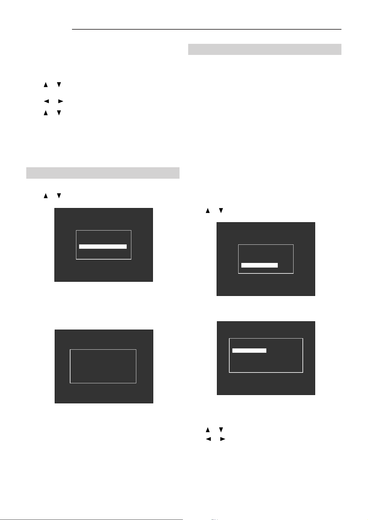
- TIMER FUNCTIONS -
DATE 11 MAY 1999
TIME 14 54 36
SWITCH ON 31 DEC
23 59
SWITCH OFF 31 DEC
23 59
DAILY ENABLE OFF
OFF
OFF
Fig. 33
Page 15
SVD 800 HD
The daily ENABLING item enables the projector to turn
on and off automatically each day when ON is set.
Note:
The values on the right are only an example.
Press or . Select the item you wish to set and
press ENTER
Press or . Select the right item.
Press or . To increase or reduce the value.
Press EXIT. Select other items and then repeat from
steps 2 to 4.
Press EXIT. The projector will return to the previous
menu.
3.20 Working time
Press or . Select WORKING TIME, ENTER
3.21 OSD OPTIONS
This menu allows you to set the MESSAGE TIME, MENU
TIME, ON SCREEN DISPLA Y of the image, the colour of
the On Screen Display and WARM-UP time.
The MESSAGE TIME item sets the time the messages
are displayed on the screen, going from 2 to 9 seconds.
The MENU TIME item sets the time the menus are displayed
on the screen going from 2 to 59 seconds.
The OSD ON PICTURE item displays the picture
parameters on the screen (contrast, brightness, saturation
and hue) when it is ON. If it is OFF they are not displayed.
The OSD COLOUR item sets the ON Screen Display
colour choosing from GREEN, MONOCHROMATIC
(white) and COLOURED (green and yellow).
The WARM-UP TIME item sets projector warm-up time
which goes from 00 (excluded) to 59 minutes (Factory
set at 10 minutes).
Press or . Select OSD OPTIONS
- MISCELLANEOUS -
- TIMER FUNCTIONS
- WARKING TIME
- OSD OPTIONS
- LOGO
Fig. 34
To display the total working time of the projector and of
each of the red, green and blue tubes.
- WARKING TIME -
PROJECTOR
RED
GREEN
BLUE
TUBE
TUBE
TUBE
0798 H
0798
0798
0798
H
H
H
Fig. 35
Press ENTER.
- MISCELLANEOUS -
- TIMER FUNCTIONS
- WARKING TIME
- OSD OPTIONS
- LOGO
- OSD OPTIONS -
MESSAGE TIME
MENU TIME
OSD ON PICTURE
OSD COLOR
WARM-UP TIME
05
30
ON
COLOR
10
Fig. 36
Fig. 37
Note:
Working time cannot be modified.
TRC working time data can be reset when a
damaged tube is replaced (which must be done by
qualified personnel).
Note:
The values given are factory set.
Press or . Select the right item.
Press or . To increase or reduce the value.
Press EXIT to exit
14
Page 16
SVD 800 HD
3.22 LOGO
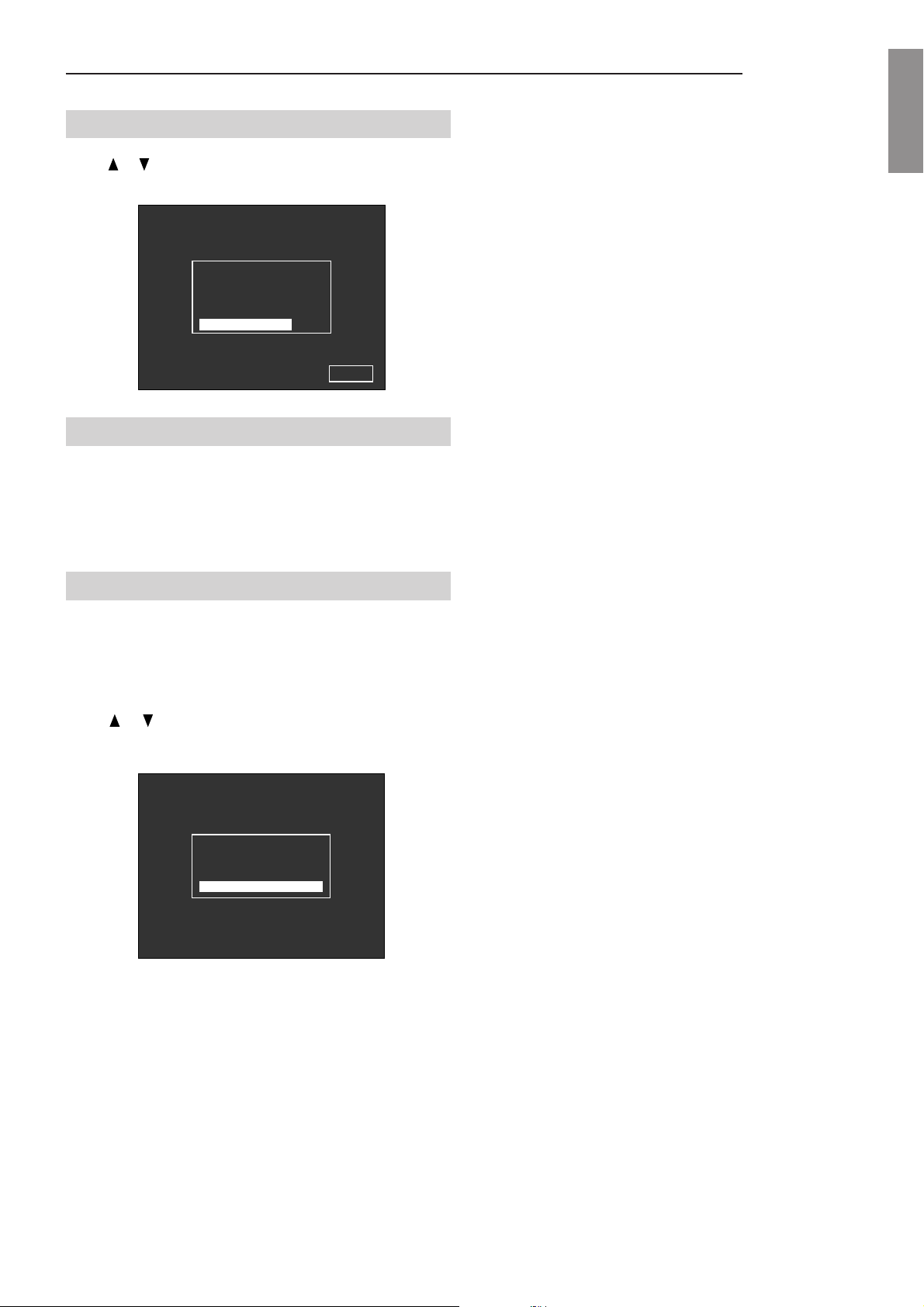
Press or . Select LOGO, ENTER to enable or disable,
EXIT to exit.
- MISCELLANEOUS -
- TIMER FUNCTIONS
- WARKING TIME
- OSD OPTIONS
- LOGO
SIM2
Fig. 38
3.23 Installation menu
THE ADJUSTMENTS DESCRIBED IN THIS
P ARAGRAPH MUST BE CARRIED OUT BY QUALIFIED
PERSONNEL. ANY ADJUSTMENTS INCORRECTLY
DONE CAN CAUSE A DETERIORATION IN PICTURE
QUALITY.
ENGLISHENGLISH
ENGLISHENGLISH
ENGLISH
3.24 How to enter the SERVICE MODE
Only by entering the SERVICE MODE will you be able to
alter deflection dimensions, colour temperature, select the
installation type, etc.
Press ••• . The MAIN MENU appears
Press or . Select INSTALL MENU
- MAIN MENU -
- VIDEO MENU
- OPTIONS
- INSTALL. MENU
Fig. 39
Press the EXIT button seven times until SERVICE MODE
appears on the screen.
Before you alter the settings check the following points:
- Mechanical centering of the video projector and tubes
- Lens focus
Note:
The protection mode is activated automatically when
switching off.
15
Page 17
SVD 800 HD
4 INSTALLATION
4.1 Installation procedure
In order to obtain the best performance from the
projector, the following procedure has to be followed
carefully and carried out by a technician.
Note:
The projector is factory-set for front ceiling projection
with a 90” screen, 4/3 format and a projector-screen
distance of 284 cm., see Fig. 49, reference (D),
page 19.
1. Choose the installation type and read the
instructions through carefully
Installation Types, page 32)
Determine the distance between the screen and the
front of the projector.
Determine the projection angle
Projection Angle Measurement page 20).
2. Remove the top and front projector covers
par. 4.2.1, Removing the cover, page 16).
3. Insert the correct spacers
Changing, page 20).
4. Prepare and install the screen.
5. Install the projector on the floor or on the ceiling
and center the screen
centering, page 23)
deflection settings.
6. Carry out a precise focus adjustment acting on
the lenses.
page 23).
7. If the installation type is the same as the factory
setting, go to step 11, otherwise continue.
8. Tilt the red and blue tubes until the three crosses
are superimposed.
centering of the tubes, page 24).
9. Switch the projector off and disconnect the power
cable.
10. Correct display on the screen
24).
11. Put the cover on the video projector.
12. Carry out a fine adjustment of the image with the
remote control.
PLETE FUNCTIONS REMOTE CONTROL, page
25).
(see: par. 4.8, Lens Focus Adjustment,
(see: par. 5, THE RC3000 COM-
(see: par. 4.5.1, Spacer
(see: par. 4.6, Projector
, maintaining the factory
(see: par. 4.9, Mechanical
(see: par. 5.9,
.
(see: par. 4.4,
(see:
(see par. 4.11, page
4.2 Removing the cover
4.2.1 Removing the top cover
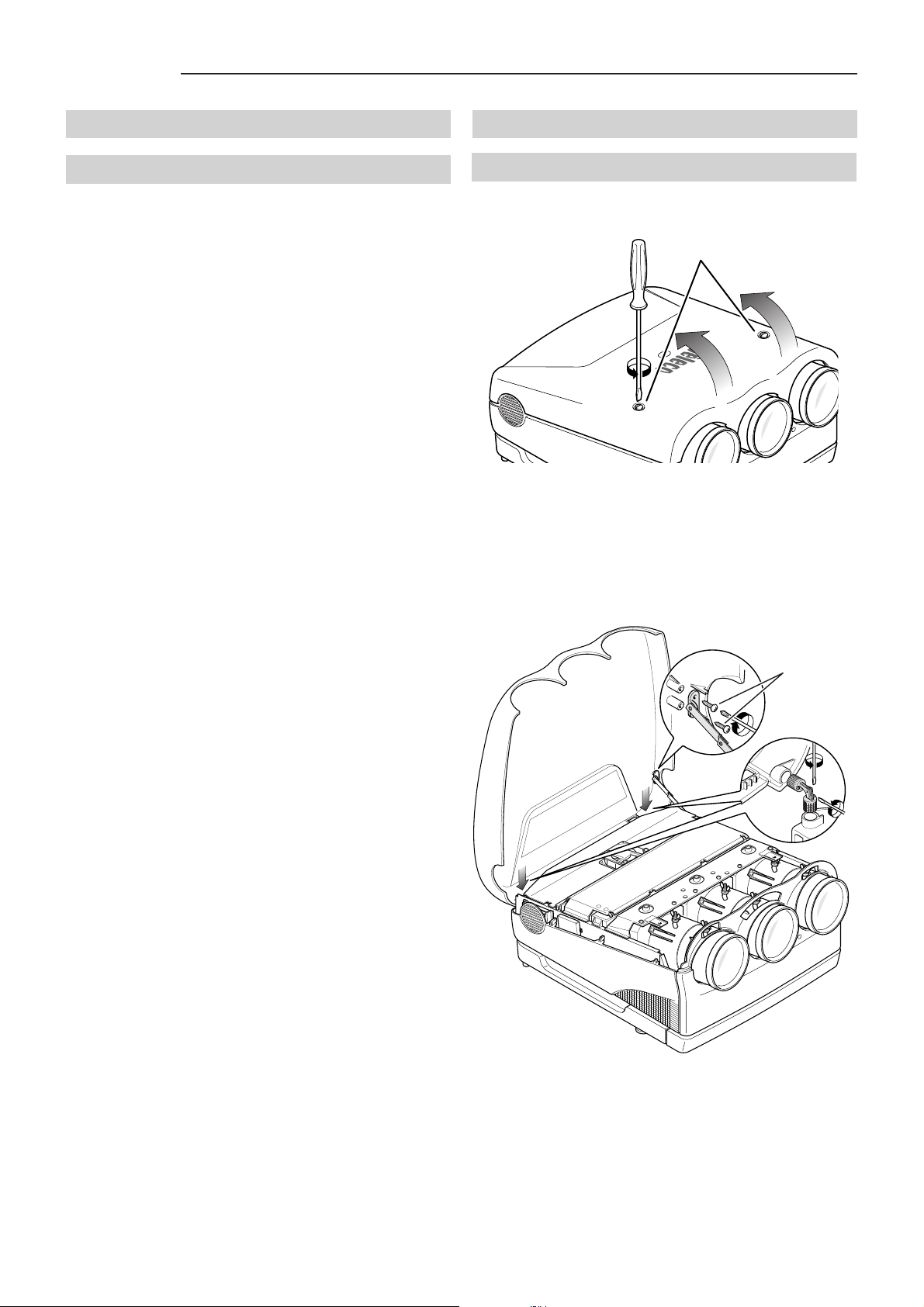
Loosen the 2 securing screws (A) and lift the cover up.
A
Fig. 40
To remove the top cover completely you must unscrew
the two locking screws (B) close to the two pivots and the
other two (C) securing the jointed rod to the cover.
C
B
Fig. 41
16
Page 18
SVD 800 HD
4.2.2 Removing the front panel
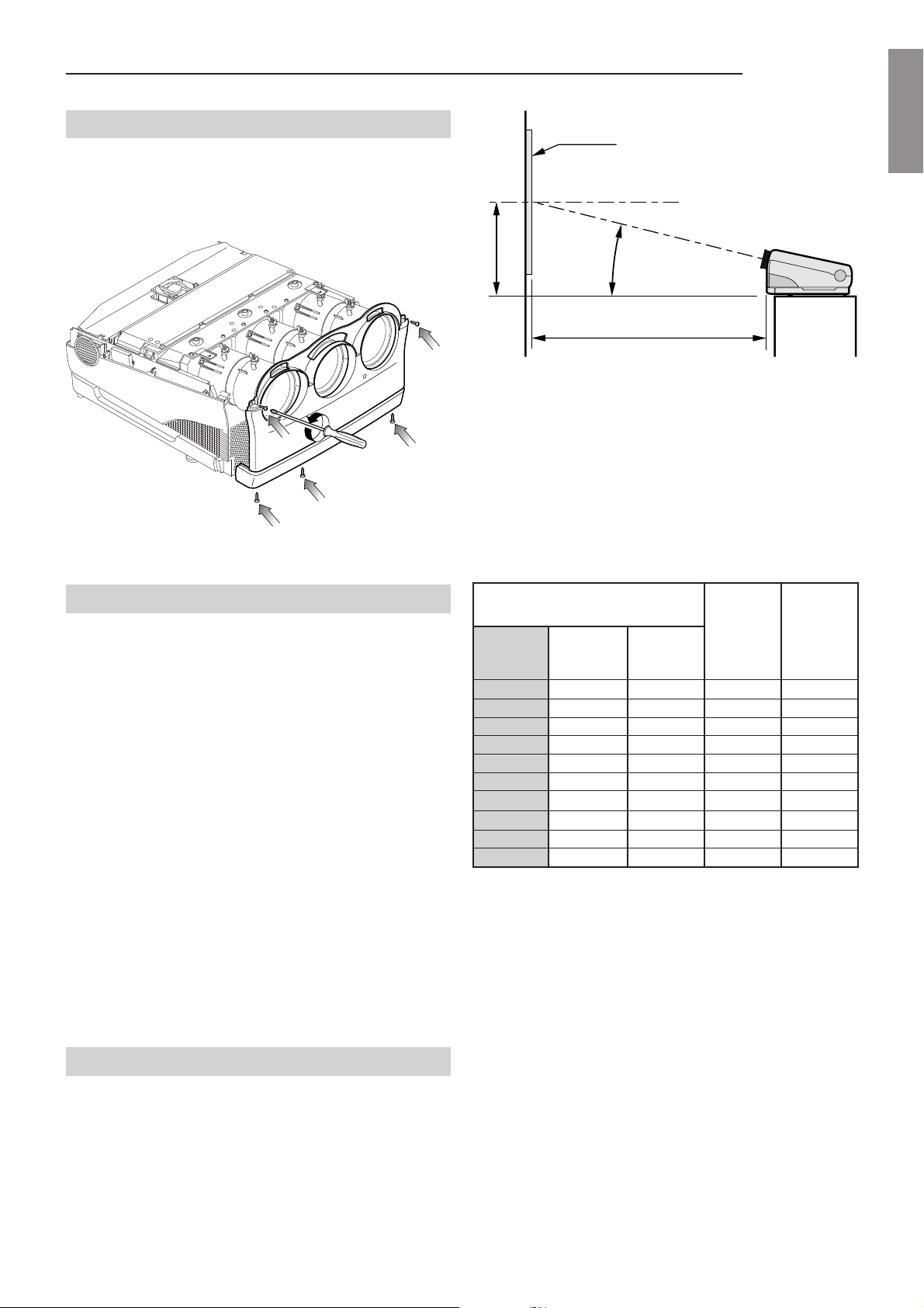
Unscrew the two screws (D) on the left and right of the
front panel. Unscrew the three screws (E) on the bottom
and take the panel off. The position of the screws is shown
by the arrows in
Fig. 42.
E
D
D
E
E
Fig. 42
SCREEN
SCREEN CENTRE
B
14°
A
Fig. 43
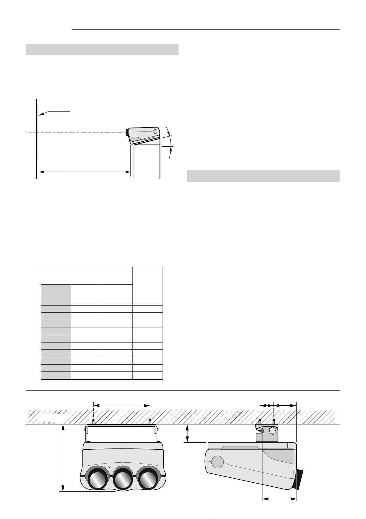
The distance between the projector and the screen
(depending on screen dimensions), is shown in the
following table.
TABLE 1: FRONT PROJECTION
A = Distance between the front panel and the screen
B = Distance between the projector’s desktop line and
screen centre.
ENGLISHENGLISH
ENGLISHENGLISH
ENGLISH
4.3.1 Installation choice
Choose one of the following possible installation
types
(see: Installation types, page 32):
DESK TOP FRONT PROJECTION
•
DESK TOP REAR PROJECTION
•
CEILING FRONT PROJECTION
•
CEILING REAR PROJECTION
•
Attention:
Correct use of the spacers, as shown in the spacer
tables, is mandatory for a perfect focus uniformity.
Check that the projector is perfectly stable.
SIM 2 MULTIMEDIA S.P.A. declines all responsibility
for damages to persons or things caused by incorrect
or careless ceiling installation which must be effected
by a qualified technician.
4.3.2 Desk-top front projection
SCREEN SIZE A B
USEFUL AREA 4/3
Diagonal Width Height
(Inches) (cm.) (cm.) (cm.) (cm.)
60” 121.9 91.4 186 72
80” 162.5 121.9 240 86
90” 182.9 137.2 266 95
100” 203.2 152.4 294 100
120” 243.8 182.9 348 116
150” 304.8 228.6 429 137
180” 365.7 274.3 510 158
200” 406.4 304.8 564 172
250” 508.0 381.0 700 208
300” 609.6 457.2 835 242
Note:
For 16/9 screen formats, measure the width and
refer to the nearest width value in the table.
.
If the size of the screen diagonal is not given in the table,
dimension A ( in cm) is determined as follows:
- Measure the screen diagonal and take the nearest
value from the table.
- Calculate the ratio between the table value and the
relative width.
- Multiply the value obtained by the actual screen width.
Attention:
The bottom of the projector must be parallel with the
floor. It is very important to know the correct
projection angle.
Example: Suppose we have a 105” screen diagonal.
100” is the nearest value in the table.
The A/Width ratio is equal to 294/203.2=1.446
A 105” screen diagonal is 213.3 wide.
So, the value of A is: 1.446x213.3=308.4 cm.
17
Page 19
SVD 800 HD
4.3.3 Desktop rear projection
For rear projection we recommend installing the projector
with the axis of the green lens orthogonal to the screen
plane; pay attention that the green lens be centered with
respect to the screen
page 23).
SCREEN
SCREEN CENTRE
By using Fresnel lenses for rear projection, it is mandatory
to install the projector orthogonal to the centre of the
screen to achieve maximum brightness and a better performance.
The distance between projector and screen is given in
the following table.
TABLE 2: DESKTOP REAR PROJECTION
(see: par. 4.6, Projector Centering
14°
C
Fig. 44
- If the measurement of the screen diagonal is not in
the table, C can be determined (in cm) as follows.
- Measure the screen diagonal and take the nearest
value from the table.
- Calculate the ratio between value C and screen width
in the table.
- Multiply the result by the actual screen width.
Example: Suppose we have a 105” screen diagonal.
100” is the nearest value in the table.
The A/Width ratio is equal to 299/203.2=1.471
A105” screen diagonal is 213.3 wide
So, the value of A is: 1.471x213.3=313.7 cm.
Note:
and refer to the nearest width value in the table.
For 16/9 screen formats, measure the width
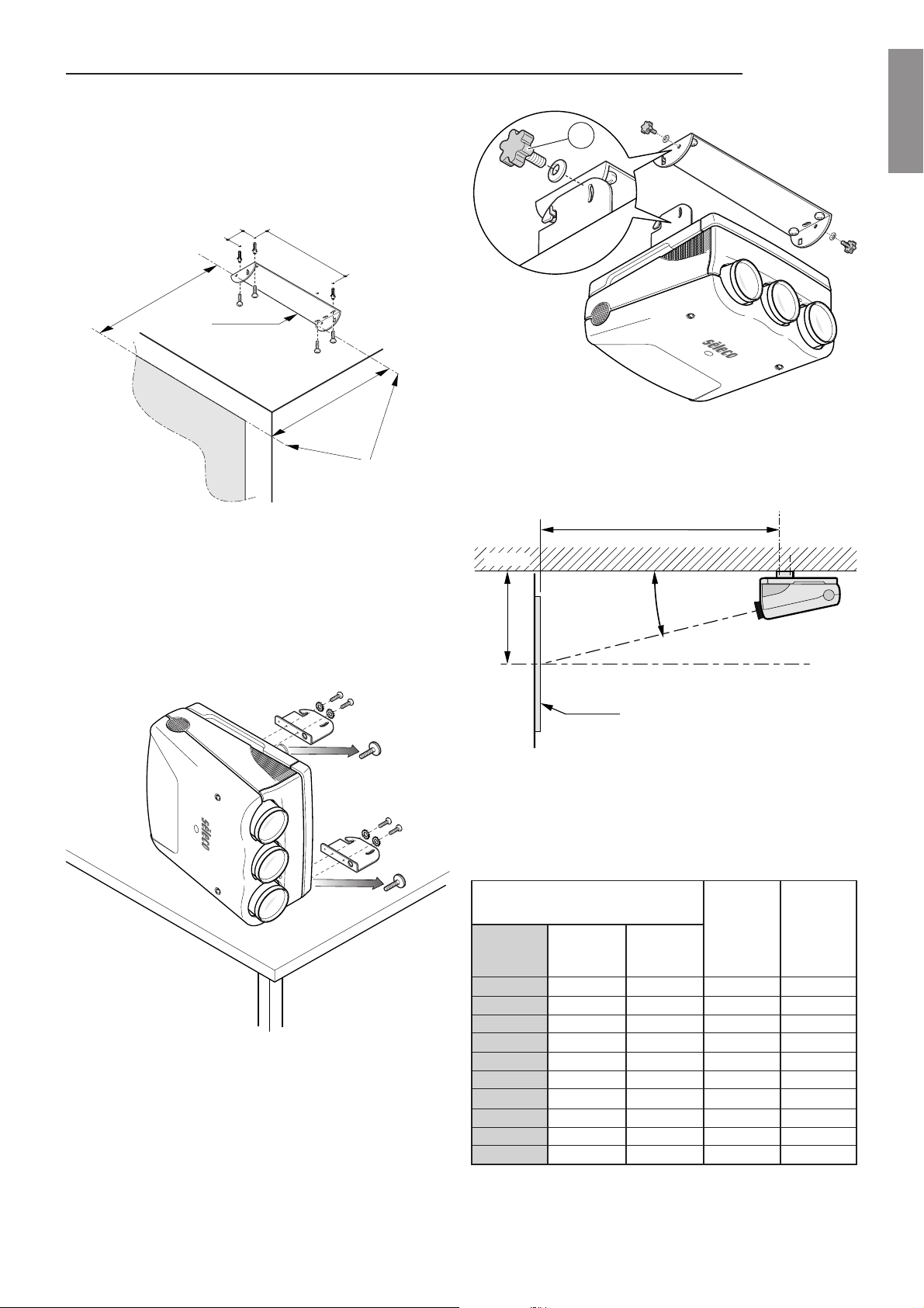
4.3.4 Ceiling front projection
Use the ceiling assembly kit (given with the projector) to
install the projector on the ceiling and proceed as follows:
To attach the projector to a solid concrete block ceiling or
brick ceiling drill 12mm dia. holes 65mm deep. Attach on
the ceiling the big bracket included in the package using
the four concrete anchors provided together with screws
and washers, USING the outer holes on the bracket, and
tighten to 25 Nm maximum torque.
C = Distance between the front panel and the screen.
SCREEN SIZE C
USEFUL AREA 4/3
Diagonal Width Height
(Inches) (cm.) (cm.) (cm.)
60” 121.9 91.4 188
80” 162.5 121.9 243
90” 182.9 137.2 271
100” 203.2 152.4 299
120” 243.8 182.9 355
150” 304.8 228.6 439
180” 365.7 274.3 522
200” 406.4 304.8 578
250” 508.0 381.0 718
300” 609.6 457.2 857
440
WALL
WARNING:
The installer must verify that the wall can support four
times the full load (mounting bracket, hardware and
electronics), the minimum thickness of the wall
support has to be 10 cm.
For concrete blocks and brick walls, do not drill mounting
holes into mortar joints, the distance between anchor and
free edge of the support wall has to be more than 18 cm.
The bracket must be fixed very carefully.
93 180
1 15
550
18
266
Fig. 45
Page 20
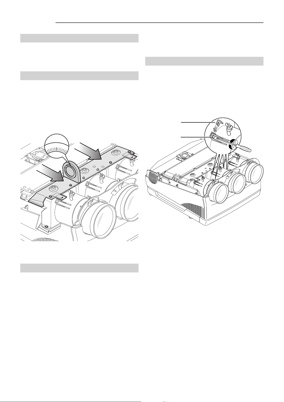
Fix the bracket, included in the pack, to the ceiling with
the four screws supplied.
Attention:
The bracket must be fixed properly and be
absolutely parallel with the screen
H
SVD 800 HD
FRONT
ENGLISHENGLISH
ENGLISHENGLISH
ENGLISH
93
=
BRACKET
SCREEN
440
FRONT
=
OBSERVE
PARALLELISM
Fig. 46
Put the projector on a table in the vertical position
(sideways)
N.B.: Take the two front feet off.
Remove the 2 screws and their washers, insert the left
bracket and fix it, using the same screws and washers,
as illustrated in the following figure.
Repeat for the right bracket.
Fig. 48
Note: the tilting angle between the base plane of the
projector and the lenses’ axis should be 14°.
D
WALL
E
14°
SCREEN CENTRE
Fig. 47
Turn the projector upside down and hang on the ceiling
with the assembly brackets
Tilt the projector to centre the vertical picture and screw
the two securing screws (H)
Note: Insert the special curved washers between the
ceiling bracket and the securing screws. For a correct
installation the concave surface of the washer should be
towards the bracket. For safety purposes, use only the
assembly kit supplied.
SCREEN
Fig. 49
TABLE 3: CEILING FRONT PROJECTION.
D = Distance between the line of the first hole of the
assembly bracket and the screen.
E = Distance between the ceiling and the screen centre.
SCREEN SIZE D E
USEFUL AREA 4/3
Diagonal Width Height
(Inches) (cm.) (cm.) (cm.) (cm.)
60” 121.9 91.4 204 81
80” 162.5 121.9 258 95
90” 182.9 137.2 284 104
100” 203.2 152.4 312 109
120” 243.8 182.9 366 125
150” 304.8 228.6 447 146
180” 365.7 274.3 528 167
200” 406.4 304.8 582 181
250” 508.0 381.0 718 217
300” 609.6 457.2 853 251
Note:
For 16/9 screen formats, measure the width and
refer to the nearest width value in the table.
19
Page 21
SVD 800 HD
4.3.5 Ceiling rear projection
Rear projection installation is done by hanging the
projector on the ceiling and following the instructions given
for front installation.
4.4 Projection angle measurement
Use a goniometer to determine the projection angle. First
of all, remove the projector’s top cover and then use the
surface shown in the figure as reference for the
goniometer.
The reference surface has an angle of 14 degrees
compared to the projector’s base when it is perfectly level.
14°
0
45
45
90
90
Attention:
Correct use of the spacers, as shown in the tables, is of
paramount importance for perfect focus uniformity.
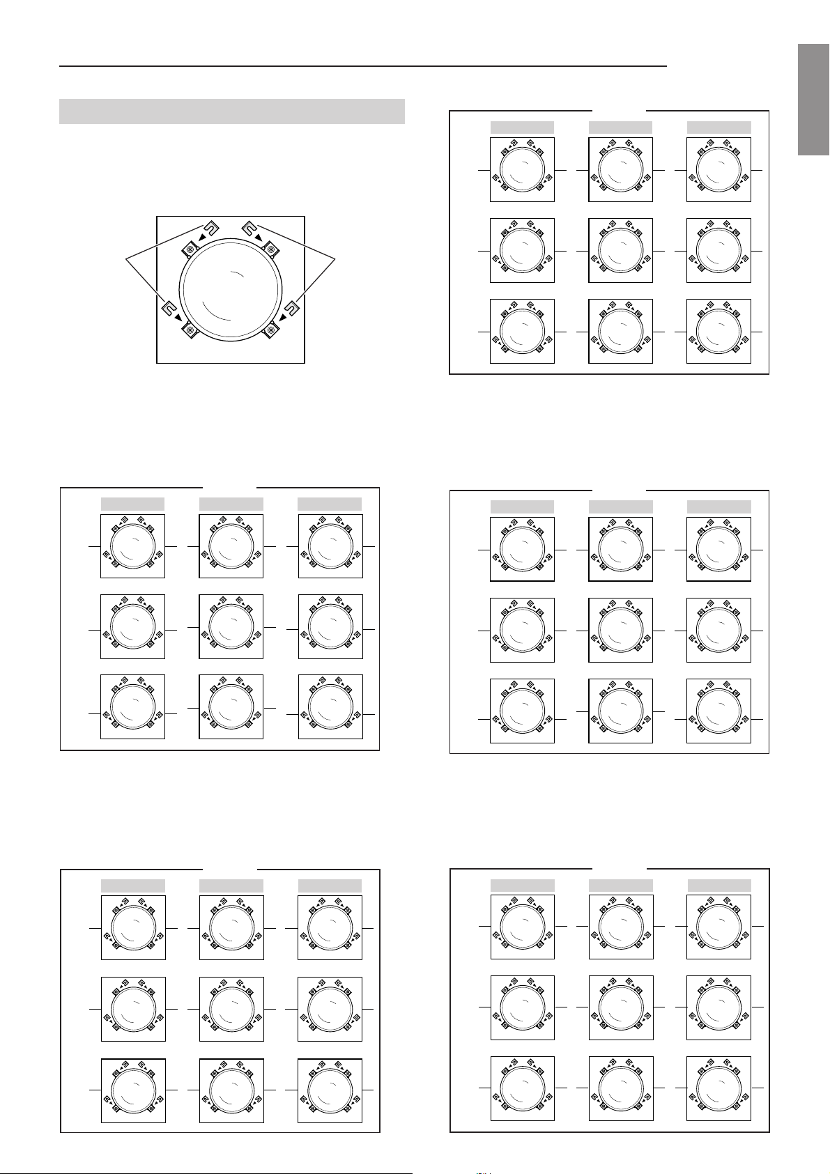
4.5.1. Spacers changing
To change the spacers first of all remove the top cover
and front panel.
Now slightly loosen the 4 screws (A) for each tube, change
the spacers (B)
tighten the screws.
You can only see two screws in the figure because the
other two are under the projection tube.
Fig. 51
B
A
(see the spacers table) and then
Fig. 50
4.5 Spacers
The projector uses some spacers for the “Scheimpflug”
correction of the lenses’ angle so as to achieve a perfect
focusing uniformity over the entire screen surface.
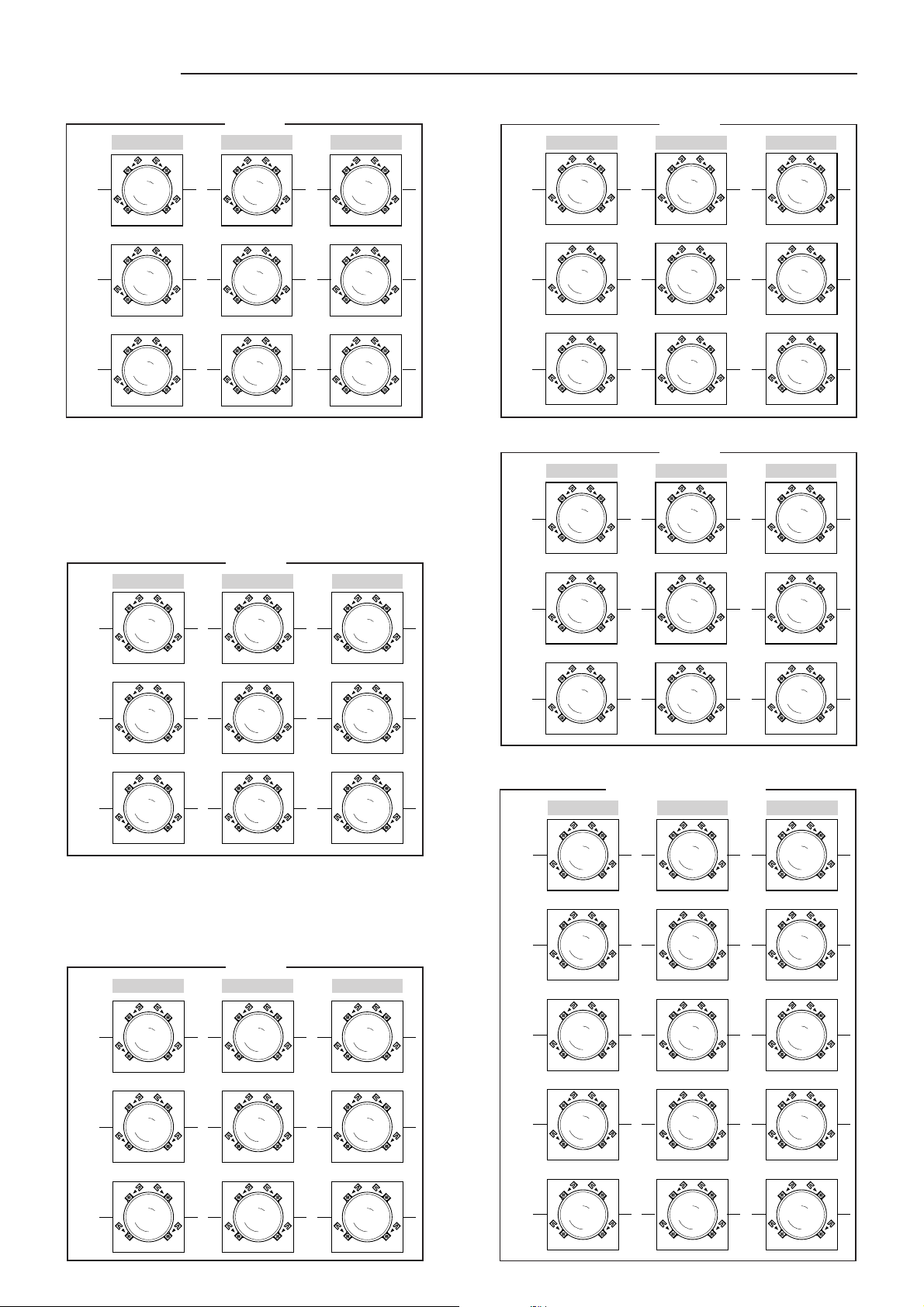
The projector is factory set with spacers for a ceiling front
installation with a 90” screen diagonal.
The projector is equipped with a complete set of optional
spacers for screens ranging from 60” up to 300”.
The spacers are mounted between the lenses and the
assembling block surface where they are fixed with 4
screws.
More than one spacer might be needed to achieve proper
adjustment.
Fig. 51
For the different installation types there are different spacer
combinations that have to be mounted.
Nota:
The spacers have their thickness value expressed
in millimetres and printed on them. The following
pieces are included with the projector:
0.2 mm: 6 pieces
0.3 mm: 6 pieces
0.5 mm: 4 pieces
1 mm: 6 pieces
2 mm: 4 pieces
The 1mm (6 pieces), 0.3 mm (6 pieces) and 0.2 mm (2
pieces) spacers are used for the factory setting (90” 14°),
while the others are inside the pack.
Note:
The angle between the base of the projector and the
axis of the tubes is mechanically fixed at 14°; so, if
the projector is installed on a perfectly horizontal table
or ceiling, projection angle will be 14°.
Fig. 52
shows where to install the spacers with the values
given in the following table.
20
Page 22
SVD 800 HD
12°
1
0,2
1
0,5
0 0,3
1
0,2
1
0,2
00
1
0,5
1
0,2
0,3 0
14°
1
0,3
1
0,3
1
0,3
1
0,5
0,2
0 0,3
00
1
0,5
0,2
1
0,3
0,3 0
18°
1
0,5
0,2
2
0 0,3
1
0,5
0,2
1
0,5
0,2
00
21
0,5
0,2
0,3 0
90"
GREENBLUE RED
4.5.2 Spacers table
Front view of the CRT.
SPACERS SPACERS
CRT LENS
Fig. 52
60"
GREENBLUE RED
1
0,5
0,2
12°
0 0,3
1
2
0,3
0,5
0,2
0,3
00
0,5
0,2
1
0,3
0,3
0,3
2
0,5
0,2
1
0
11
0,3
12°
0 0,3
100"
GREENBLUE RED
11
00
1
0,3
0,3 0
ENGLISHENGLISH
ENGLISHENGLISH
ENGLISH
1
1
0,5
0,3
0,2
14°
0 0,3
1
1
0,2
0,2
18°
0 0,3
1
0,3
12°
0 0,3
1
0,3
0,2
14°
0 0,3
1
1
18°
0 0,3
2
22
0,5
0,2
0,3
00
2
2
1
0,3
0,3
00
0,3
2
80"
GREENBLUE RED
1
1
0,5
0,3
0,2
0,3
00
1
2
2
0,5
00
22
00
1
0,3
1
0,5
2
0,5
0,2
0,3
0,3
2
1
0,3
0,3
1
0,5
0,2
0,3 0
21
0,3 0
2
0,3
0,3 0
1
0,5
0,3
0,2
0
1
1
0,2
0,2
0
1
0,3
0,3
0,2
1
1
21
0,2
1
0,5
1
1
0,2
0,2
1
14°
0 0,3
1
0,3
0,3
18°
0 0,3100
00
1
1
0,5
0,2
0,2
0,5
0,2
0,5
0,2
120"
GREENBLUE RED
0,5
0,3
12°
0 0,2
1111
14°
0 0,2
1
0,3
18°
0 0,2100
1
0,5
0,3
00
0,2
00
1
1
0,3
0,5
0,5
0,3
1
0,5
0,3 0
1
0,5
0,2
0,2
0,3 0
1 0,5
0,2 0
1
0,2
0,2 0
1
0,50,3
0,2 0
1
0,2
1
0,3
0,3
0,3
1
1
0,3
Page 23
SVD 800 HD
60"
0 0,5
0,2
0,5
0,2
00
0
00
00,5
0,2
0,5
0,2 0
80"
0 0,5 00,500
0 0,5
000,5 0
90"
100"
0 0,3 00,300
0 0,3
000,3 0
120"
0 0,2 00,200
0 0,2
000,2 0
150"
300"
0,2 0,3 0,20,300
0,2 0,3
000,3 0,2
Projections at 0¡
GREENBLUE RED
150"
GREENBLUE RED
0,2
0,5
0,2
0,5
0,2
10,5
12°
0 0,2
0,5
0,3
00
0,5
11
0,3
0,5
0,3
14°
0 0,2
1
00
11
0,2
18°
0 0,2100
180"
GREENBLUE RED
10,5
0,3
12°
0,2 0,3
11
14°
0,2 0,3
0,5 0,5
00
0,5
0,2
0,3
00
0,5
0,3
1 0,5
0,2 0
0,2 0
1
0,2
0,2 0
1 0,5
0,3 0,2
1
0,2
0,3 0,2
0,2
0,5
0,3
1
0,3
1
250"
GREENBLUE RED
0,5
0,2
0,5
0,3
0,3
0,2
0,3
0,2
0,5
0,3
12°
0,2 0,3
0,5
0,2
0,5
0,3
00
0,3
0,2
0,3 0,2
0,5
0,3
0,2
0,3
14°
0,2 0,3
0,3
000,3 0,2
10,5
0,5
0,2
0,5
0,2
18°
0,2 0,3 00
0,3 0,2
300"
GREENBLUE RED
0,3 0,3 0,3 0,3
12°
00
0,3
0,2
14°
00
0,3
0,2
18°
0000
00
0,3
0,2
0000
0,3
0,5 0,5
0,2
0,3
0,50,5
0,2
0,3
0,2
0,5
0,2
0,5
0,2
1 0,5
00
00
0,3
0,30,3
0,3
0,2
0,3
0,2
18°
12°
14°
18°
1
0,2
0,2 0,3100
0,3
11
1
0,3
0,3 0,2
200"
GREENBLUE RED
10,5
0,3
0,2 0,3
0,3
0,2 0,3
0,2 0,3
1
0,2
0,5 0,5
00
10,5
000,3 0,2
0,5
1
0,3
00
1 0,5
0,3 0,2
1 0,5
0,50,5
0,5
1
0,2
0,3
0,3 0,2
0,2
0,3
0,3
1
1
22
Page 24
SVD 800 HD
4.6 Projector centering
The first step towards a good installation is centering the
projector with respect to the screen. This can be done
using two pieces of equally long cord, as illustrated in the
following figure:
SCREEN
CORDS OF THE SAME LENGTH
CENTRE
Reference
corner
SCREEN AND PROJECTOR
Reference
corner
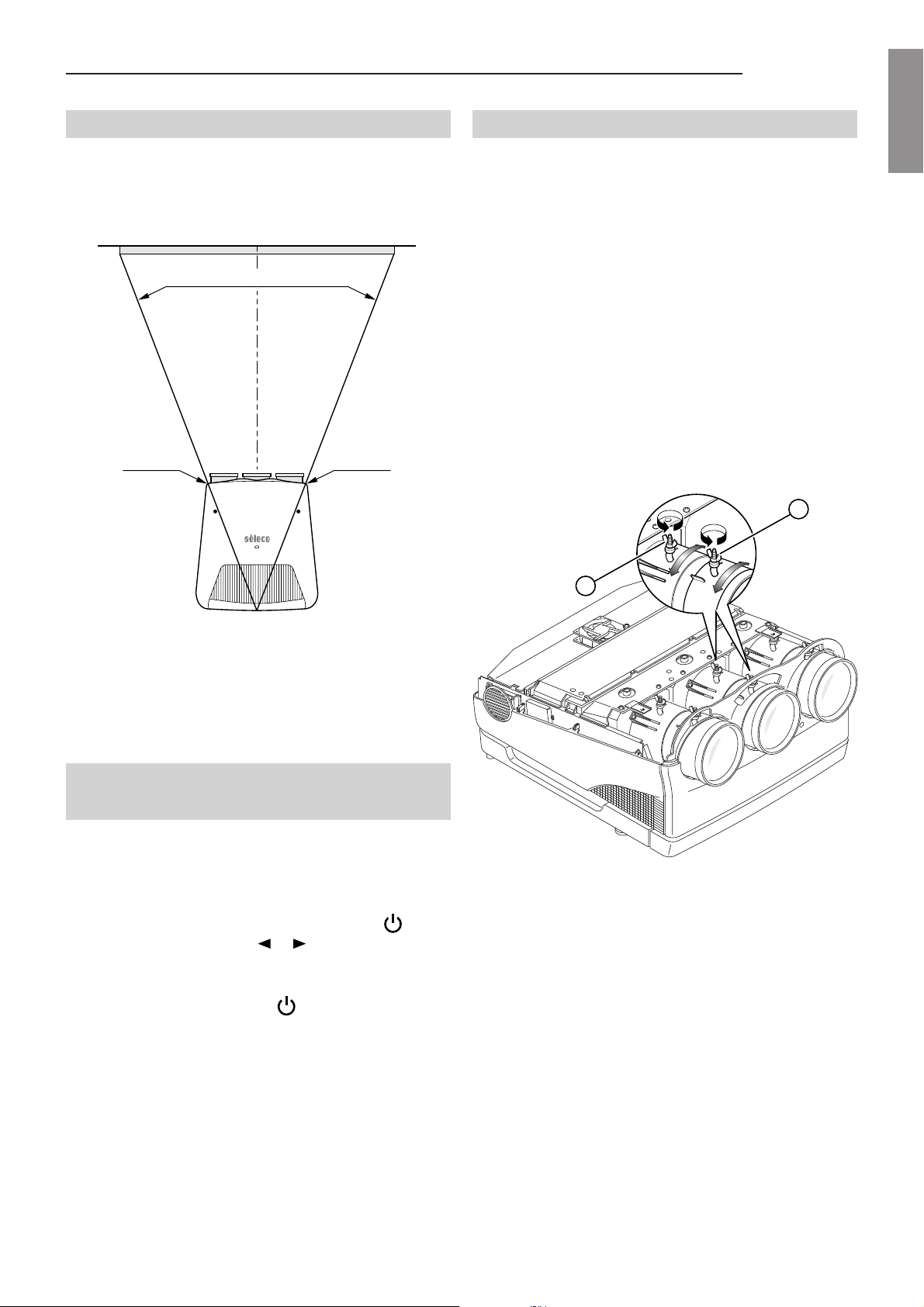
4.8 Lens focus adjustment
Each lens must be focused individually with the tubes
on, one at a time and following this procedure:
1. Select the HATCH test pattern by pressing the TEST
button on the remote control. An external pattern signal
can be used if you prefer.
2. Adjust with a low contrast (e.g. 30) and a medium-low
background brightness (e.g. 40)
3. Turn the other tubes off using the push buttons R,G,B,
on the remote control.
4. Loosen the wing screw (B)
turn the lens assembly either to the right or left to adjust
the focus of the picture in the middle of the screen and
then tighten the screw. (B).
Fig. 54
of the green lens,
A
ENGLISHENGLISH
ENGLISHENGLISH
ENGLISH
Fig. 53
It is necessary to check that the position of the two corners
at the front of the projector is centred with respect to the
position of the cords, as illustrated in the figure.
Once you have done this you can be sure that the screen
and the projector are orthogonal and centred, essential
conditions for the best performance.
4.7 Optical and electrical
adjustments
Turn the projector on with the main switch on the left of
the rear panel; the red pilot light indicates the stand-by
state.
If the projector remains in stand-by press the button
on the remote control or the or arrow buttons on the
rear panel. The green pilot light indicates the projector is
on.
To turn the projector off, press or the main switch.
Proceed with installation using the internal test pictures. They
can be used by pressing TEST on the complete functions
remote control (RC3000) and selecting the most appropriate
test signal.
B
Fig. 54
5. Loosen the wing screw (A) of the green lens, turn the
lens assembly either to the right or left to adjust the
focus of the picture on the borders of the screen and
then tighten the screw (A).
6. Look at the screen closely and check the result; repeat
the adjustments if necessary.
7. Repeat steps 3, 4 and 5 for the red and blue lenses.
Attention:
DO NOT move the electrostatic focus adjustment
potentiometers. They were factory-set and should only
be adjusted by qualified personnel.
23
Page 25
SVD 800 HD
4.9 Mechanical centering of the
tubes
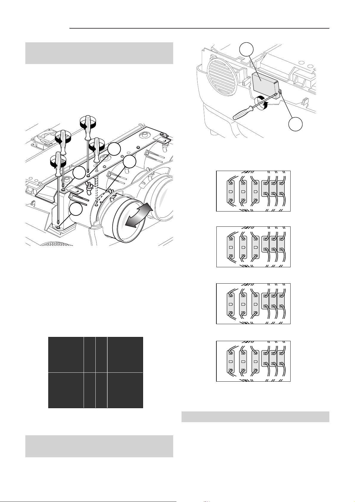
For an installation different to factory setting (90”) the
mechanical centering of the red and blue tubes needs to
be adjusted.
Select the CROSS HATCH signal with the remote control.
Looking at the following figure, unscrew (only 2 turns!)
the screws (A-B-C-D) of the red tube.
C
D
B
A
A
B
Fig. 57
3. If necessary modify the setting as shown in the
following figures.
DESK TOP FRONT PROJECTION
BLUE WIRE YELLOW WIRE
RED
Horizontal Deflection Connectors
BLUE
GREEN
RED WIRE BROWN WIRE
R
G
B
Vertical Deflection Connectors
Fig. 58
Fig. 55
Physically move the tube until the red cross is perfectly
over the green. Tighten the four screws when you have
finished.
Repeat this procedure again for the blue tube.
At this point it is necessary to recheck the focus of the red
and blue.
Fig. 56
CEILING FRONT PROJECTION
RED WIRE BROWN WIRE
RED
Horizontal Deflection Connectors
CEILING REAR PROJECTION
RED
Horizontal Deflection Connectors
DESKTOP REAR PROJECTION
RED
Horizontal Deflection Connectors
N.B.:
In the case of ceiling to floor installations or vice
BLUE
GREEN
BLUE WIRE YELLOW WIRE
RED WIRE
GREEN
BLUE WIRE
BLUE WIRE
GREEN
RED WIRE
BLUE
BLUE
R
G
YELLOW WIRE
R
G
BROWN WIRE
BROWN WIRE
R
G
YELLOW WIRE
B
Vertical Deflection Connectors
B
Vertical Deflection Connectors
B
Vertical Deflection Connectors
versa, see par. 5.11.3, Linearity, page 33.
Fig. 59
Fig. 60
Fig. 61
4.10Correct screen viewing
(deflection inversion)
1. Switch the projector off.
2. Take the (A) cover off by unscrewing screw (B)
See
Fig. 57.
4.11 Convergence adjustment
To adjust convergence you must read very carefully
the chapter concerning convergence adjustment from
the remote control,
32.
24
see par. 5.11, Convergence, page
Page 26
SVD 800 HD
5 THE COMPLETE FUNCTION RC3000 REMOTE CONTROL
5.1 Complete function RC3000
remote control
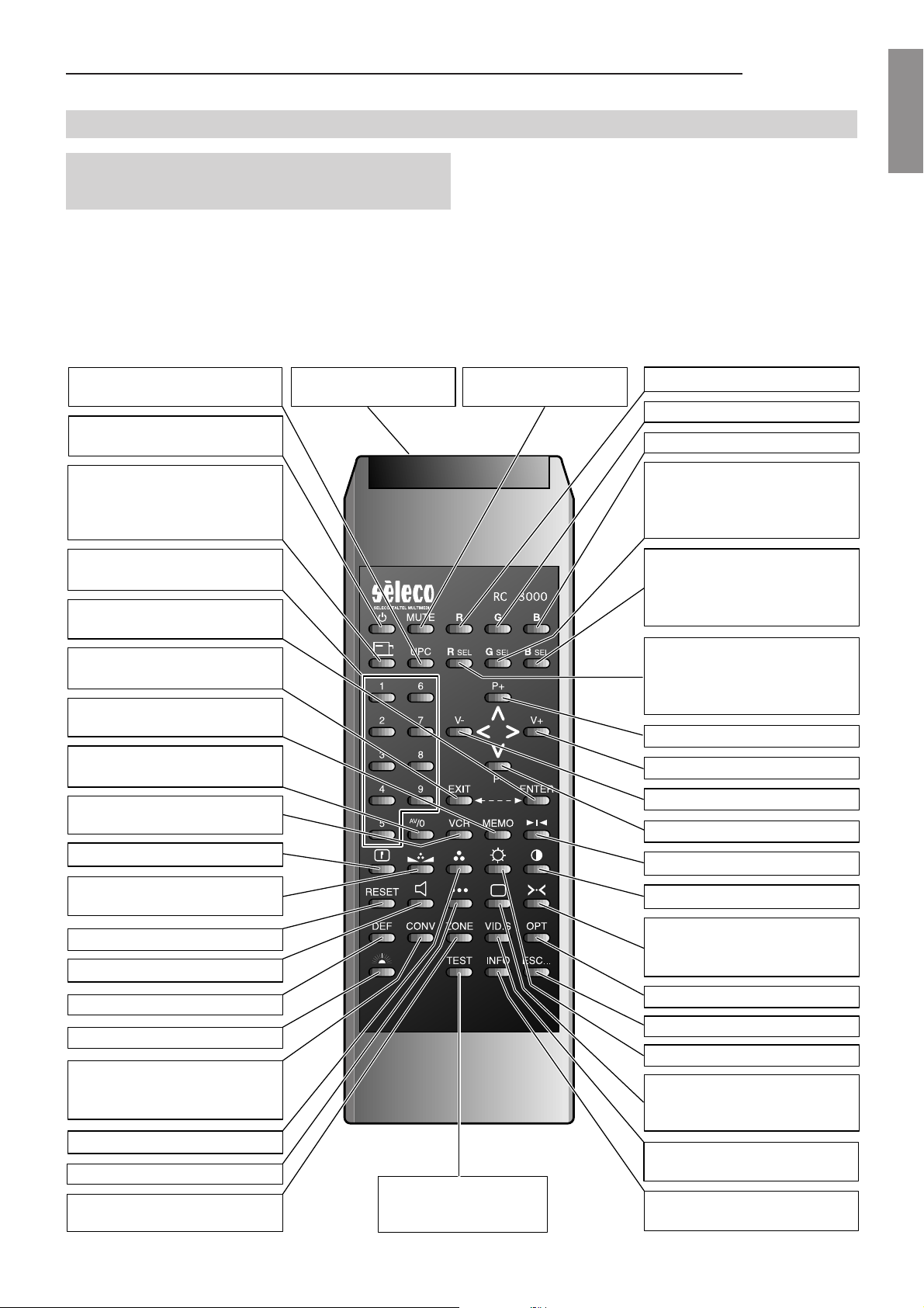
There are two remote controls for the video projector. One,
the RC3000, is a complete function remote control used
to install the projector while the other one, the RC3100, is
for normal use. Both control the projector with infrared
rays. With the RC3000 remote control you can connect
Turns the UPC converter
on/off.
Turns the video projector
on/off.
Selects one of the available
screen formats (Small, Normal, Wide, Cinema, Letter
Box).
Selects the right input directly.
Confirms current choice or goes to
the next page in the current menu.
Returns to the previous menu
or page.
Stores video settings.
Displays the selected video
input menu.
Selects FAST or SLOW sync
filter.
Adjusts peaking.
Adjusts hue for the NTSC
standard.
Resets the adjustments made.
Not active.
Jack connector for
main cable.
via cable directly to the video projector’s IR input so as to
avoid any technical problems.
N.B.: (The cable is supplied with the projector. Standard
length is 8m.).
The following pages explain the functions of the buttons
on the RC3000 remote control.
Switches the picture
on/off.
Switches the red tube on/off.
Switches the green tube on/off.
Switches the blue tube on/off.
Switches the green channel
adjustments on/off. In the
video menu it lets you change the white balance.
Switches the blue channel
adjustments on/off. In the
video menu it lets you change
the white balance.
Switches the red channel
adjustments on/off. In the
video menu it lets you change
the white balance.
Up arrow.
Right arrow.
Left arrow.
Down arrow.
Still frame (FREEZE).
Adjusts contrast.
Restores the normalised
values of brightness, contrast,
colour, hue, peaking.
ENGLISHENGLISH
ENGLISHENGLISH
ENGLISH
Not active.
Lights up the remote control buttons.
In the installation mode, it lets
you enter the convergence
menu.
Adjusts colour (saturation).
Accesses the service menu.
In the installation mode it lets
you enter the zones menu.
Generates a test signal
selectable from eight different ones.
25
Enters the options menu.
Exits any menu.
Adjusts brightness.
Enters the video menu or adjusts
brightness, contrast, colour,
hue, peaking.
Enters the video installation
menu.
Displays projector information.
Fig. 62
Page 27
SVD 800 HD
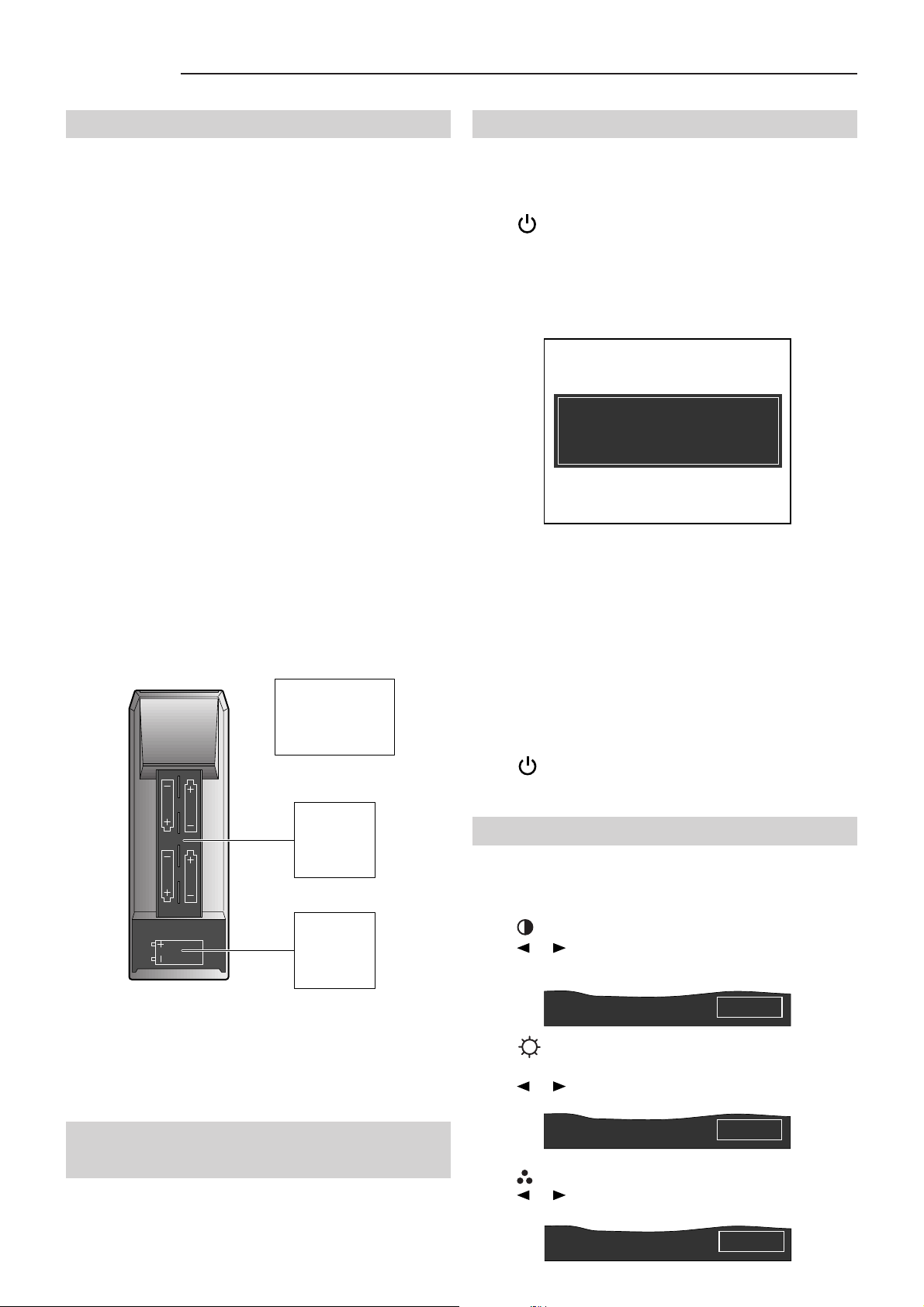
5.2 Batteries
Handling the remote control and batteries:
- Avoid exposing the remote control to heat and humidity
- When not using the remote control for a long period of
time, remove the batteries.
- Avoid using the RC 3000 remote control with the infrared
control and service light on for a long time as battery
life would then be reduced.
- Do not use new and old batteries together or batteries
of a different voltage or type.
- Handle the remote control with care.
- Use the remote control within its operating range (about
10 metres and a 30° angle)
Note:
The RC3000 remote control is powered by four AA
1.5 V batteries and one 9V battery, IEC6F22.
RC 3000
BACK OF THE
REMOTE
CONTROL
5.4 Turning the projector on
Press the mains switch; the red stand-by LED on the rear
panel turns on.
Press , or one of the buttons from 1÷9.
The red LED becomes green ON.
A white screen appears with the message indicated below .
FOR AN OPTIMAL USE THE WHITE
PATTERN WILL REMAIN ON THE
SCREEN FOR 10 MINUTES !
FOR IMMEDIATE USE PRESS ESC
Fig. 64
Always leave the projector to warm up for ten minutes
after switching it on.
The message disappears temporarily after about 40
seconds after which it reappears for 5 seconds at
approximately 40 second intervals.
Press any key to exit from the initial screen and to see the
picture immediately after having turned the projector on
if, for instance, the adjustment has been completed and
warming up is unnecessary.
WARM-UP time can be modified or excluded,
OSD OPTIONS, page 14
.
Press to switch off and then move the power switch
round to OFF.
see par. 3.21
4
AA 1.5 V
batteries
1
9 V O L T
9V battery
IEC6F22
Fig. 63
5.3 How the RC 3000 remote control
works
The following paragraphs describe the functions of the
RC3000 remote control.
5.5 Picture adjustment
T o change the contrast, brightness, colour , hue and peaking
directly you can use the following buttons:
Press . CONTRAST , selects the contrast setting.
Press or to change the value.
CON 80
Press . BRIGHTNESS, selects the brightness
setting.
Press or to change the value.
LUM 50
Press . COL. selects the colour setting.
Press or to change the value.
COL 60
26
Fig. 65
Fig. 66
Fig. 67
Page 28
SVD 800 HD
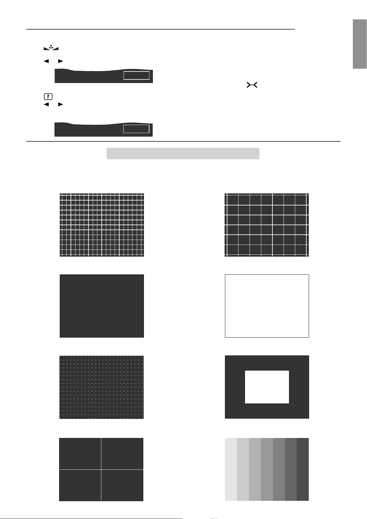
Press . HUE, selects the hue setting, only for
NTSC signals
Press MEMO if you wish to store all the settings when
one of the functions is displayed.
Press or to change the value.
Press ESC to exit.
TIN 50
Fig. 68
N.B.:
If your press all the values stored in the
displayed signal bank are recalled.
Press . PEAK, selects the peaking setting
Press or to change the value.
DET 100
Fig. 69
5.6 Test patterns
To select a test pattern press TEST. The following eight patterns will appear in sequence.
Press ESC to exit
18X13 HATCH
9X7 HATCH
ENGLISHENGLISH
ENGLISHENGLISH
ENGLISH
H CHARACTERS
HHHHHHHHHHHHHHHHHHHHHHHH
HHHHHHHHHHHHHHHHHHHHHHHH
HHHHHHHHHHHHHHHHHHHHHHHH
HHHHHHHHHHHHHHHHHHHHHHHH
HHHHHHHHHHHHHHHHHHHHHHHH
HHHHHHHHHHHHHHHHHHHHHHHH
HHHHHHHHHHHHHHHHHHHHHHHH
HHHHHHHHHHHHHHHHHHHHHHHH
HHHHHHHHHHHHHHHHHHHHHHHH
HHHHHHHHHHHHHHHHHHHHHHHH
HHHHHHHHHHHHHHHHHHHHHHHH
HHHHHHHHHHHHHHHHHHHHHHHH
HHHHHHHHHHHHHHHHHHHHHHHH
HHHHHHHHHHHHHHHHHHHHHHHH
HHHHHHHHHHHHHHHHHHHHHHHH
HHHHHHHHHHHHHHHHHHHHHHHH
DOTS
CROSS
WHITE FIELD
WHITE WINDOW
COLOUR BARS
27
Fig. 70
Page 29
SVD 800 HD
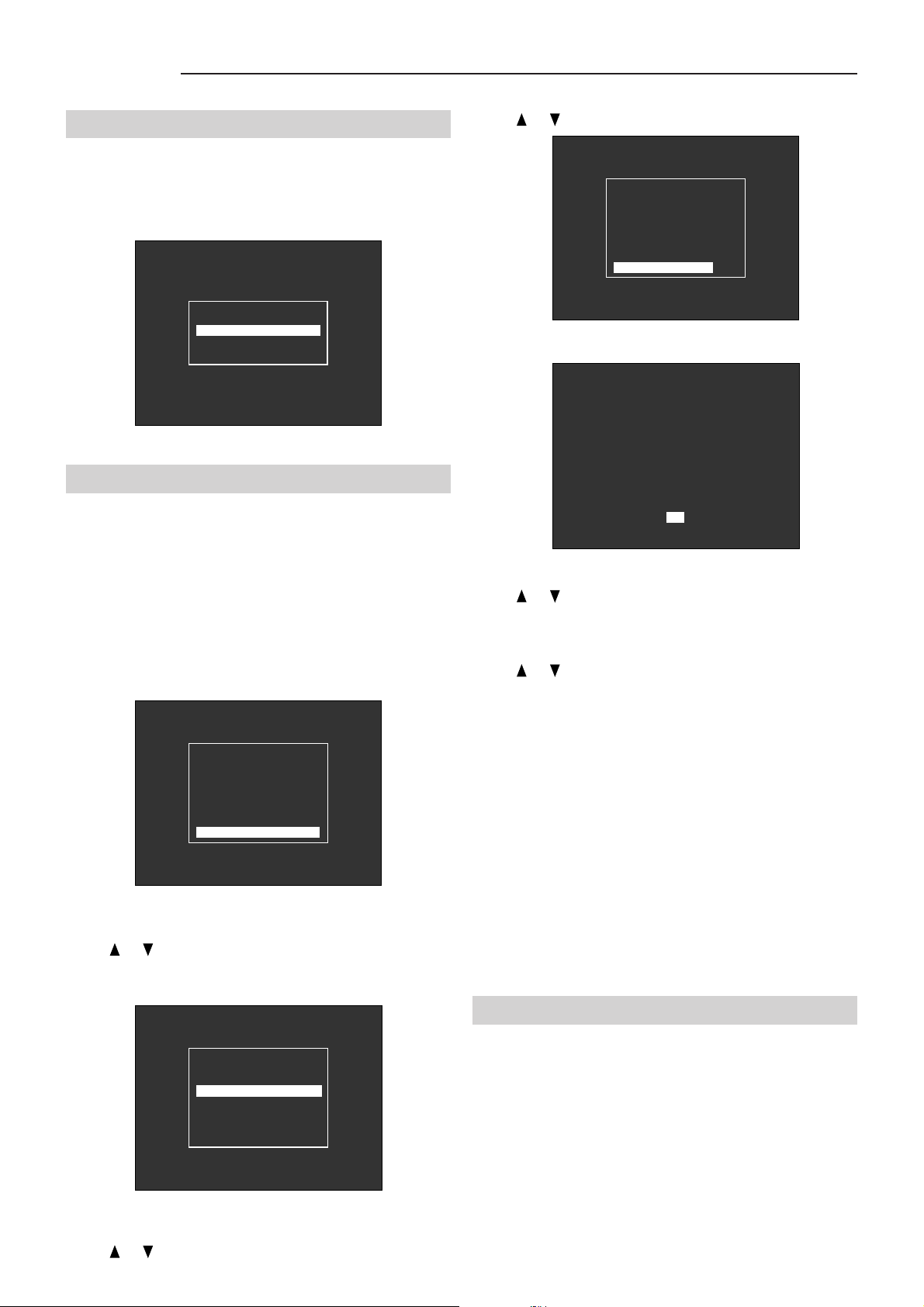
VIDEO MENU
Press VID.S. the VIDEO MENU appears.
To adjust the various sub menus
see: par. 3.13, VIDEO
MENU, page 11.
- MAIN MENU -
- VIDEO MENU
- OPTIONS
- INSTALL. MENU
Fig. 71
5.7 White balance
To select one of the set colour temperatures (3200°K,
6500°K, 9300°K, USER, BANK)
MENU, page 13.
N.B.:
To adjust the white balance enter the SERVICE
MODE (see par. 3.24, page 15).
Press VID.S., ENTER. The VIDEO MENU appears.
see par. 3.18, WHITE
Press or . Select EDIT PRESET.
- WHITE MENU -
- SET TO 3200°K
- SET TO 6500°K
- SET TO 9300°K
- SET TO USER
- SET TO BANK
- EDIT PRESET
Fig. 74
Press ENTER. WHITE BALANCE 6500 °K appears
- WHITE BALANCE -
6500°K
BLACK XX XX XX
WHITE XX XX XX
R G B
Fig. 75
Press R,G,B. Select the BLACK of the colour to adjust.
Press or to adjust.
Press Rsel, Gsel, Bsel. Select the WHITE of the
colour to adjust
Press or to adjust.
- VIDEO MENU -
- QSD MANAGER
- UPC MANAGER
- INPUT SETTINGS
- BLANKING
- EHT NOISE RED.
- WHITE MENU
Press or . Select WHITE MENU, ENTER.
WHITE MENU appears
- WHITE MENU -
- SET TO 3200°K
- SET TO 6500°K
- SET TO 9300°K
- SET TO USER
- SET TO BANK
- EDIT PRESET
Fig. 72
Press MEMO when adjusting is finished.
N.B.:
When adjusting is finished, by pressing EXIT the
message MEMORIZE COLOUR TEMPERATU-
RE? appears, press ENTER to store.
- White balance can be adjusted with the contrast and
brightness value in use.
- Whenever a picture adjustment is active on the screen
like, for instance, CONT, white balance regulation is
impossible. Press EXIT.
- By selecting SET TO BANK you can personalise the
white for each current signal bank.
5.8 MEMORY MANAGER
With this menu
or delete a memory bank containing all the projector
adjustments or to store new ones.
30 user presettable memory banks are available from
(00÷29).
see Fig. 77
you can select, copy , move
Press or . Select 6500°K, ENTER
Fig. 73
10 memory banks (30÷40) are factory-set for ceiling
projection with a 90” 4/3 format screen. These banks can
be copied (COPY) they cannot be loaded (LOAD), deleted
(DEL) or moved (MOVE).
28
Page 30
SVD 800 HD
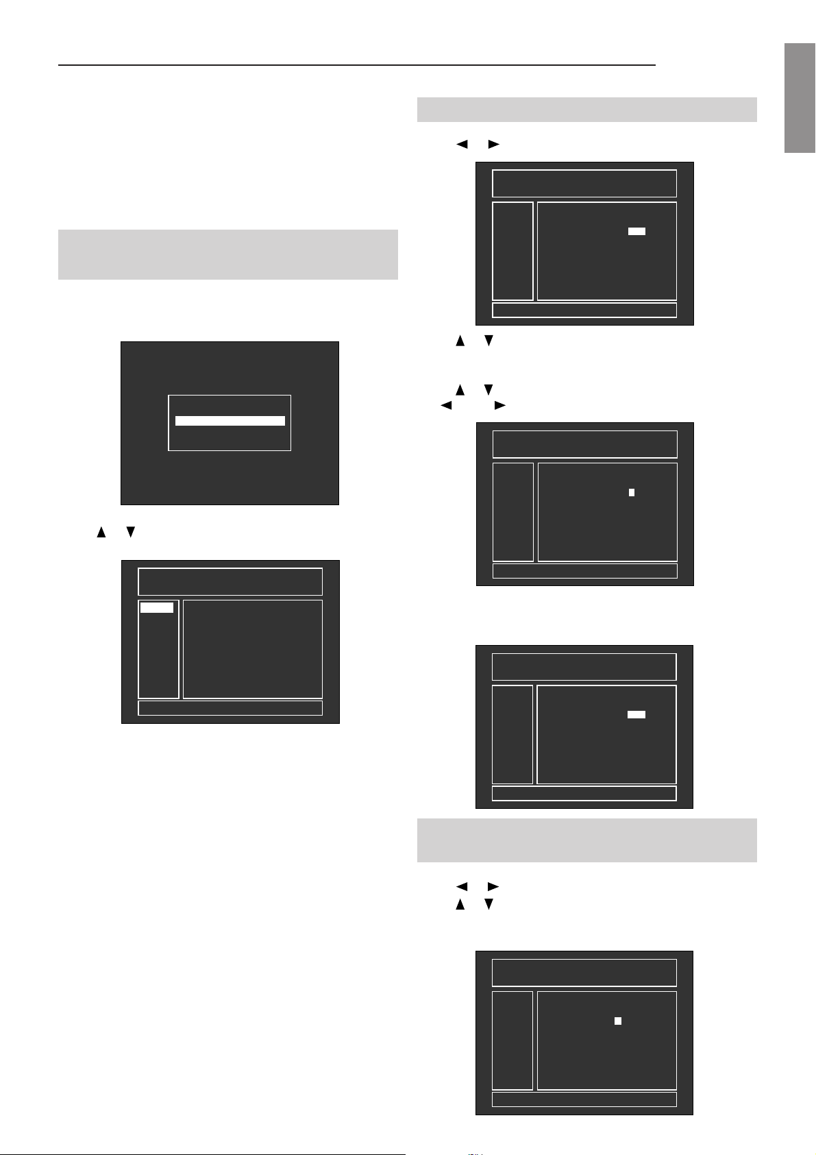
(F) indicates which ratio flag was stored by the user during
the adjustments.
The horizontal and vertical frequencies are measured
by the projector and stored in the relative memory bank
each time you save an adjustment. When the projector is
switched on the last memory bank used is recalled.
5.8.1 How to enter the memory
manager
Enter the SERVICE MODE,
Press OPT. OPTIONS appear
- MEMORY MANAGER
- INSTALL. TYPE
- MISCELLANEOUS
Press or . Select MEMOR Y MANAGER, ENTER
- MEMORY MANAGER -
LOAD
COPY
MOVE
DEL
RECALL A BANK FROM MEMORY
-BANK 01: It indicates that bank 01 has been recalled. It
is important when the input frequencies do
not match those stored in the bank.
-N.: Bank number
-HOR: Horizontal frequency. It is measured by the
software and stored in the memory bank.
-VER: Vertical frequency. It is measured by the
software and stored in the memory bank.
-F: Flag. with this function you can change the
video format: Normal, Small, Letter box,
CInema, Wide.
-LABEL: Name of the memory bank (label decided by
the user).
see par. 3.24 page 15.
- OPTIONS -
01BANK SIGNAL NAME PAL
HOR VER F LABEL
N
00
01
02
03
04
05
06
07
08
09
33.7
15.6
15.7
31.5
31.5
31.2
48.4
64.3
71.7
44.9
60
N ATSC1080
50
N
60
N
70
N
60
N
60
N
00
N
60
N
76
N
60
N ATSC720P
PAL
NTSC358
DOS-VGA
VGA-640
31K 100HZ
VESA 1024
64K 60HZ
SUN 76HZ
Fig. 76
Fig. 77
5.8.2 How to insert a label
Press or . Select LABEL
- MEMORY MANAGER 01BANK SIGNAL NAME PAL
LOAD
COPY
MOVE
DEL
HOR VER F LABEL
N
00
01
02
03
04
05
06
07
08
09
33.7
15.6
15.7
31.5
31.5
31.2
48.4
64.3
71.7
44.9
60
50
60
70
60
60
00
60
76
60
N ATSC1080
N
N
N
N
N
N
N
N
N ATSC720P
PAL
NTSC358
DOS-VGA
VGA-640
31K 100HZ
VESA 1024
64K 60HZ
SUN 76HZ
EDIT BANK NAME
Press or to select in which memory bank you wish to
change the label.
Press ENTER. The LABEL will appear in green.
Press or to scroll the letters of the alphabet and use
the left or right arrows to move to the next letter.
- MEMORY MANAGER 01BANK SIGNAL NAME PAL
LOAD
COPY
MOVE
DEL
HOR VER F LABEL
N
00
01
02
03
04
05
06
07
08
09
33.7
15.6
15.7
31.5
31.5
31.2
48.4
64.3
71.7
44.9
60
50
60
70
60
60
00
60
76
60
N ATSC1080
N
N
N
N
N
N
N
N
N ATSC720P
PAL - - - - -
NTSC358
DOS-VGA
VGA-640
31K 100HZ
VESA 1024
64K 60HZ
SUN 76HZ
EDIT BANK NAME
When you have written the right name press ENTER,
ENTER. The label will appear written in white with a
message under the table.
- MEMORY MANAGER 01BANK SIGNAL NAME PAL
LOAD
COPY
MOVE
DEL
BANK NAME STORED
HOR VER F LABEL
N
00
01
02
03
04
05
06
07
08
09
33.7
15.6
15.7
31.5
31.5
31.2
48.4
64.3
71.7
44.9
60
50
60
70
60
60
00
60
76
60
N ATSC1080
N
N
N
N
N
N
N
N
N ATSC720P
PAL
NTSC358
DOS-VGA
VGA-640
31K 100HZ
VESA 1024
64K 60HZ
SUN 76HZ
5.8.3 How to change an aspect ratio
(F)
Press or . Select F.
Press or to select in which memory bank you wish to
modify the aspect ratio flag.
Press ENTER, the following figure will appear.
- MEMORY MANAGER 01BANK SIGNAL NAME PAL
LOAD
COPY
MOVE
DEL
EDIT ASPECT RATIO : NORMAL
29
HOR VER F LABEL
N
00
01
02
03
04
05
06
07
08
09
33.7
15.6
15.7
31.5
31.5
31.2
48.4
64.3
71.7
44.9
60
50
60
70
60
60
00
60
76
60
N ATSC1080
N
N
N
N
N
N
N
N
N ATSC720P
PAL
NTSC358
DOS-VGA
VGA-640
31K 100HZ
VESA 1024
64K 60HZ
SUN 76HZ
Fig. 78
Fig. 79
Fig. 80
Fig. 81
ENGLISHENGLISH
ENGLISHENGLISH
ENGLISH
Page 31
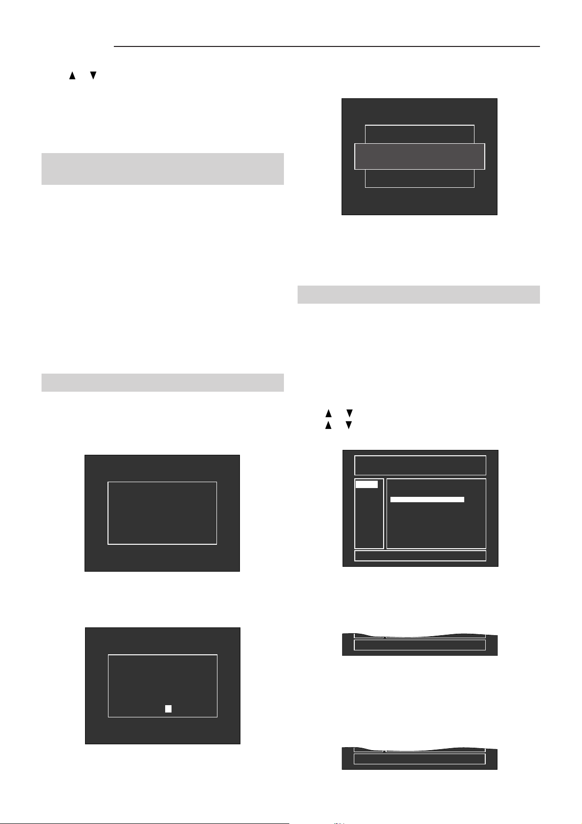
SVD 800 HD
Press or . Select the right ratio from among: N
(Normal), S (Small), L (Letter box),
C (Cinema), W (Wide).
Press ENTER to confirm.
The following message will appear under the table: EDIT
ASPECT RATIO.
5.8.4 Horizontal and vertical
frequencies
The horizontal and vertical frequencies are measured by
the projector and stored in the relative memory bank each
time you store a change.
If the input signal does not match the frequency stored in
the memory bank the software will automatically recall
the memory bank with the frequency nearest to that of
the input signal, in this order: horizontal frequency , vertical
frequency, aspect ratio.
If the frequencies of the input signal are different from
those stored in the memory bank, the software will not
recognise the frequency and, if you store settings, it will
ask to create a new memory bank.
5.8.5 How to store a new input signal
Press MEMO only after the convergence adjustments
have been done, the following will appear:
Enter the label;
see par. 5.8.2 page 29.
Press ENTER and the following will appear:
NEW INPUT SIGNAL
CONFIRM NEW NAME: XXXXXXXX
ENTER NAME = XXXXXXXX
Fig. 84
Press ENTER. The menu will appear with the number of
the bank where it is stored.
Press ESC to exit.
5.8.6 LOAD
This item on the MEMORY MANAGER menu allows
the user to load and change a memory bank
containing all the projector adjustments.
This is possible only if there is a match between the input
frequencies and the frequencies stored in the memory
bank.
Press or . Select LOAD, ENTER
Press or . Select a memory bank whose frequencies
are like the current signal.
NEW INPUT SIGNAL
FH = XX.X KHZ FV = XX HZ
CREATE MEMORY BANK?
Press ENTER and the following will appear:
NEW INPUT SIGNAL
FH = XX.X KHZ FV = XX HZ
ENTER NAME = – –––––––
Fig. 82
- MEMORY MANAGER 01BANK SIGNAL NAME PAL
LOAD
COPY
MOVE
DEL
LOAD BANK
HOR VER F LABEL
N
00
01
02
03
04
05
06
07
08
09
33.7
15.6
15.7
31.5
31.5
31.2
48.4
64.3
71.7
44.9
60
N ATSC1080
50
N
60
N
70
N
60
N
60
N
00
N
60
N
76
N
60
N ATSC720P
PAL
NTSC358
DOS-VGA
VGA-640
31K 10HZ
VESA 1024
64K 60HZ
UN 76HZ
Fig. 85
Press ENTER.
The following message will appear under the table.
RECALL A BANK FROM MEMORY
Fig. 86
If the input signal frequencies (horizontal and vertical) do
not match the selected memory bank, the following
message will appear under the table.
Fig. 83
FREQUENCY MUST MATCH !
Fig. 87
30
Page 32
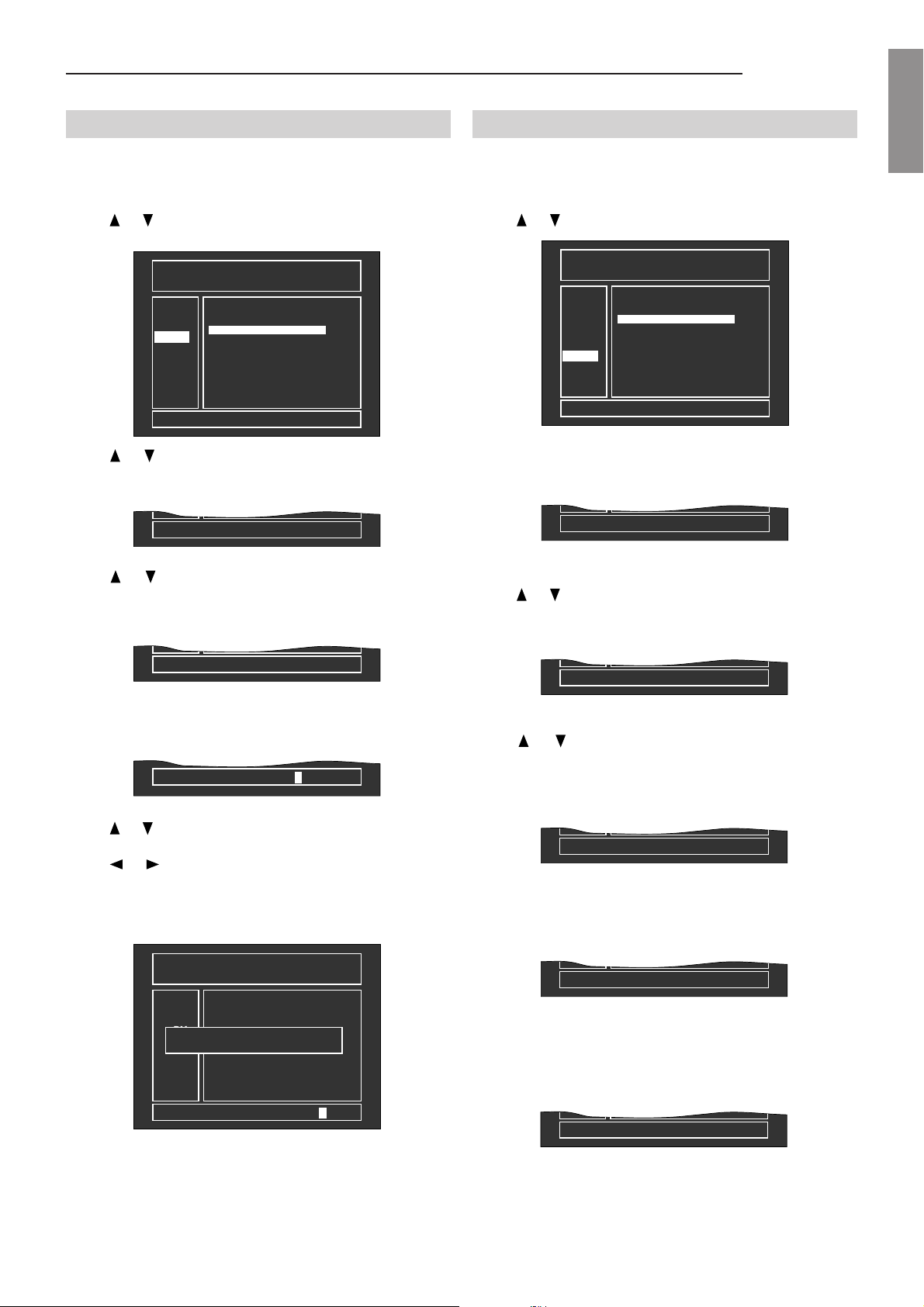
SVD 800 HD
5.8.7 Copy (COPY)
This function allows you to copy a memory location
containing settings in another location.
Press or . Select COPY, ENTER.
- MEMORY MANAGER 01BANK SIGNAL NAME PAL
LOAD
COPY
MOVE
DEL
COPY A BANK TO ANOTHER ONE
Press or . Select a memory bank (from 00 to 29) to
be copied.
Press ENTER. The following message will appear:
COPY A BANK FROM 01 TO
Press or . Select the memory bank (from 00 to 29)
where to copy the information.
Press ENTER to confirm. The following message will
appear:
HOR VER F LABEL
N
00
01
02
03
04
05
06
07
08
09
33.7
15.6
15.7
31.5
31.5
31.2
48.4
64.3
71.7
44.9
60
50
60
70
60
60
00
60
76
60
N ATSC1080
N
N
N
N
N
N
N
N
N ATSC720P
PAL
NTSC358
DOS-VGA
VGA-640
31K 10HZ
VESA 1024
64K 60HZ
UN 76HZ
Fig. 88
Fig. 89
5.8.8 MOVE (MOVE)
This function allows you to move a memory bank to
another position on the list.
Press or . Select MOVE.
- MEMORY MANAGER 01BANK SIGNAL NAME PAL
LOAD
COPY
MOVE
DEL
MOVE A BANK TO ANOTHER ONE
Press ENTER. The following message will appear:
MOVE A BANK FROM
Press or . Select the memory bank (from 00 to 29).
Press ENTER. The following message will appear:
HOR VER F LABEL
N
00
01
02
03
04
05
06
07
08
09
33.7
15.6
15.7
31.5
31.5
31.2
48.4
64.3
71.7
44.9
60
50
60
70
60
60
00
60
76
60
N ATSC1080
N
N
N
N
N
N
N
N
N ATSC720P
PAL
NTSC358
DOS-VGA
VGA-640
31K 10HZ
VESA 1024
64K 60HZ
UN 76HZ
Fig. 93
Fig. 94
ENGLISHENGLISH
ENGLISHENGLISH
ENGLISH
COPY A BANK FROM TO XX ?
Fig. 90
Press ENTER to confirm. If the destination memory bank
is free you will be asked to enter a name for the bank and
the following message will appear:
ENTER NEW BANK NAME - - - - - - - -
Fig. 91
Press or . Select the characters of the name (label).
Press or . Change the cursor position.
Repeat until the name is complete and then press ENTER.
The following message will appear:
- MEMORY MANAGER 01BANK SIGNAL NAME PAL
LOAD
COPY
CONFIRM NEW NAME : XXX
MOVE
DEL
ENTER NEW BANK NAME XXX - - - - -
HOR VER F LABEL
N
00
01
02
03
04
05
06
07
08
09
33.7
15.6
15.7
31.5
31.5
31.2
48.4
64.3
71.7
44.9
60
50
60
70
60
60
00
60
76
60
N ATSC1080
N
N
N
N
N
N
N
N
N ATSC720P
PAL
NTSC358
DOS-VGA
VGA-640
31K 10HZ
VESA 1024
64K 60HZ
UN 76HZ
Fig. 92
MOVE A BANK FROM 01 TO
Fig. 95
Press or . Select a free destination memory bank
(from 00 to 29).
Press ENTER. The following message will appear:
MOVE A BANK FROM 01 TO 13 ?
Fig. 96
Press ENTER to confirm. The following message will
appear:
MOVE BANK TO ANOTHER ONE
Fig. 97
Press EXIT to return to the previous menu.
Note:
If the destination bank is not free the following
message will appear:
DESTINATION MUST BE EMPTY
Fig. 98
Press ENTER to confirm.
Note:
The copy will be made even if the horizontal and
vertical frequencies do not match those of the video input
signal.
31
Page 33
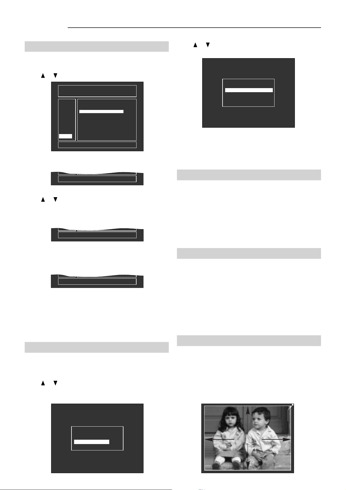
SVD 800 HD
5.8.9 DELETE (DEL)
This function allows you to delete a memory bank.
Press or . Select the DEL function.
- MEMORY MANAGER 01BANK SIGNAL NAME PAL
LOAD
COPY
MOVE
DEL
DELETE A BANK FROM MEMORY
Press ENTER . The following message will appear:
ARE YOU SURE TO DELETE !
Press or . Select the memory bank to be deleted
The following message will appear:
ARE YOU SURE TO DELETE 01 ?
HOR VER F LABEL
N
00
01
02
03
04
05
06
07
08
09
33.7
15.6
15.7
31.5
31.5
31.2
48.4
64.3
71.7
44.9
60
50
60
70
60
60
00
60
76
60
N ATSC1080
N
N
N
N
N
N
N
N
N ATSC720P
and press ENTER.
PAL
NTSC358
DOS-VGA
VGA-640
31K 10HZ
VESA 1024
64K 60HZ
UN 76HZ
Fig. 99
Fig. 100
Fig. 101
Press or . Select the installation type.
Press ENTER to confirm.
- INSTALL. TYPE -
- DESKTOP / FRONT
- DESKTOP / REAR
- CEILING / FRONT
- CEILING / REAR
Fig. 104
Press EXIT to return to the previous menu.
In the case of ceiling to floor installations or vice versa,
see par. 4.10 Correct screen viewing, page 24
5.10 Fine picture adjustments
This paragraph is very important to achieve a perfect
fine adjustment of the projector once it has been
installed. Read the following pages carefully.
Attention:
It is very important to synchronise the projector with the
most frequently used input signals. The settings of each
signal type must be stored in a memory bank.
Press ENTER to delete the memory bank.
The following message will appear:
BANK 01 DELETED
Fig. 102
The cursor will return to the left of the menu.
If the memory bank you are deleting is the one in use, it
will be deleted and the first bank with the same input signal
frequency will be loaded.
5.9 Installation types
Enter the SERVICE MODE,
Press OPT.
Press or . Select INSTALL TYPE, ENTER to
confirm.
see par. 3.24 page 15
5.11 Convergence (CONV)
Enter the SERVICE MODE
Press CONV (convergence adjustments).
In this way you can make all the adjustments necessary
to align the image of the green, red and then the blue
tube on the screen.
Press EXIT, ENTER to scroll the convergence adjustment
menus in sequence.
Press Rsel, Gsel, Bsel to enable the colour to be adjusted.
see par. 3.24, page 15.
5.11.1 PHASE
The PHASE control is enabled on external images.
If an internal test signal is selected and the phase is
enabled, the current external signal is displayed
automatically.
RASTER
- OPTIONS -
- MEMORY MANAGER
- INSTALL. TYPE
- MISCELLANEOUS
Fig. 103
- PICTURE -
Fig. 105
32
Page 34
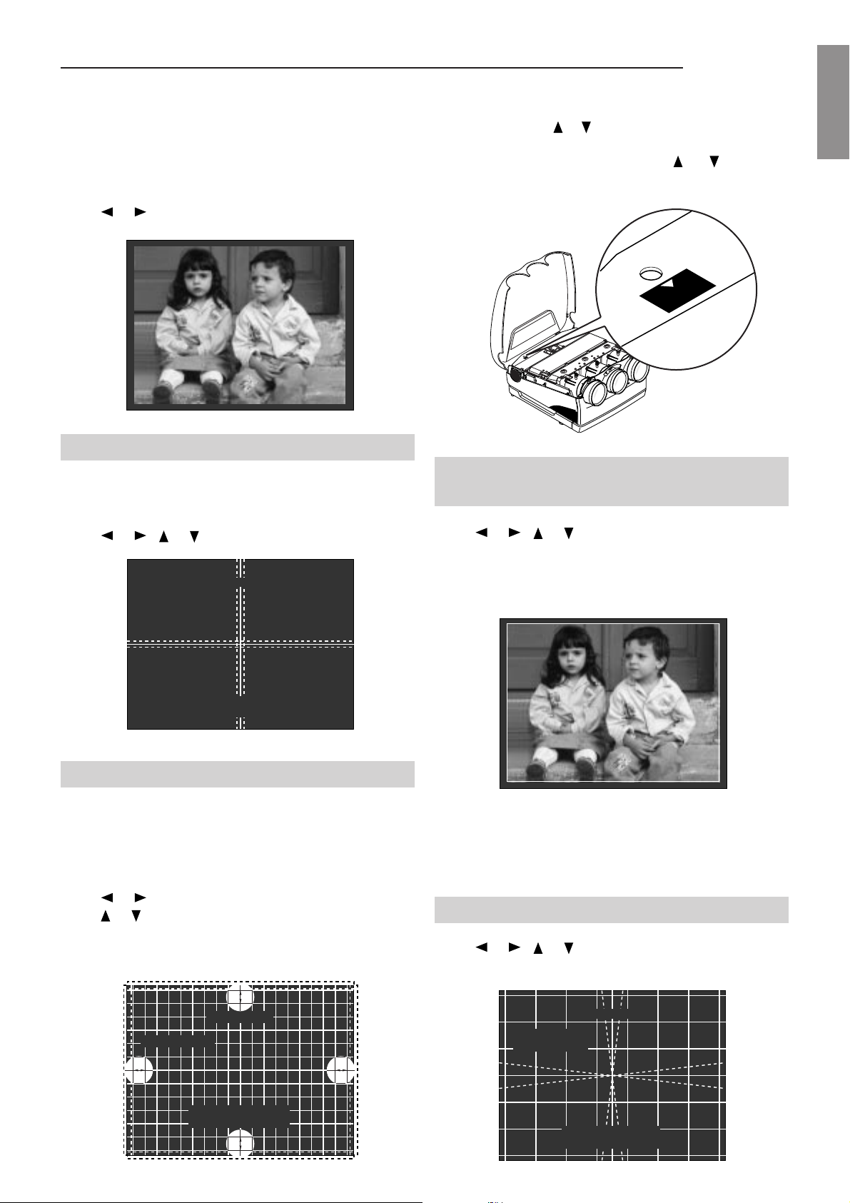
SVD 800 HD
V
E
R
T
IC
A
L
L
IN
E
A
R
IT
Y
VERTICAL
LINEARITY
Use this function to centre the external signal image with
respect to the raster.
This adjustment is common to the three colours R.G.B.
Press CONV
Press or to centre the image on the screen.
PHASE
CRT = R G B
H. VALUE = XX
Fig. 106
5.11.2 SHIFT
This function allows you to shift the raster to the right,
left, up or down.
N.B.:
In the case of ceiling to floor installations or vice
versa, press
or
to position V . VALUE=30, adjust
P3 (LIN. PRESET) on PC 098 (vertical def.) for a
good vertical linearity, press
or
adjustment.
5.11.4 Picture dimensions
(SIZE)
for a fine
Fig. 109
ENGLISHENGLISH
ENGLISHENGLISH
ENGLISH
Press or , or to adjust.
SHIFT
CRT = R G B
ADJ = R - -
H. VALUE = XX
V. VALUE = XX
Fig. 107
5.11.3 LINEARITY
This function is used to modify the distance between
the cross hatch lines until they are equal.
This adjustment is common to the three colours R.G.B.
Press or so that parts (a) are equal in width.
Press or so that parts (b) are equal in width.
Press or , or to adjust.
This adjustment is common to the three colours R.G.B.
SIZE
CRT = R G B
H. VALUE = XX
Fig. 110
Attention:
Raster size is directly related to projector
resolution.The bigger the raster is the greater the
resolution will be.
5.11.5 SKEW
Press or , or to adjust.
b
LINEARITY
CRT = R G B
a a
H. VALUE = XX
V. VALUE = XX
b
CRT = R G B
ADJ = R - -
Fig. 108
SKEW
H. VALUE = XX
V. VALUE = XX
Fig. 111
33
Page 35
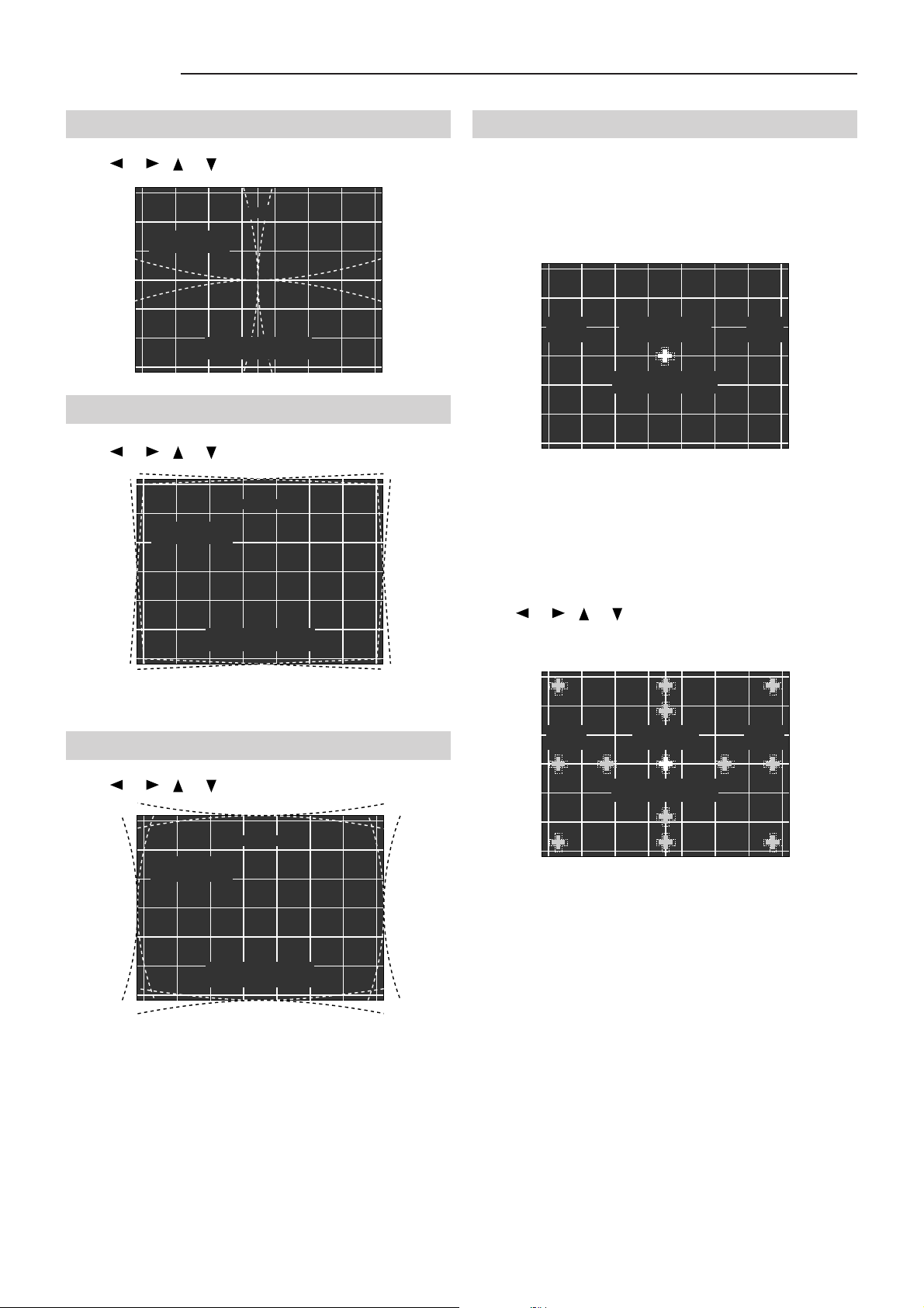
SVD 800 HD
5.11.6 BOW
Press or , or to adjust.
BOW
CRT = R G B
ADJ = R - -
H. VALUE = XX
V. VALUE = XX
5.11.7 KEYSTONE
Press or , or to adjust.
KEYSTONE
CRT = R G B
ADJ = R - -
Fig. 112
5.11.9 ZONES
This function adjusts the red zones after having adjusted
convergence and when the red and green lines converge.
Press ZONE. The ZONE menu appears.
CRT
R G B
ZONE
- SHIFT FINE -
H. VALUE = XX
V. VALUE = XX
This menu changes according to the zone you are
adjusting.
Press EXIT, ENTER to scroll the ZONE menus in
sequence.
ADJ
R - -
Fig. 115
H. VALUE = XX
V. VALUE = XX
5.11.8 PINCUSHION
Press or , or to adjust.
PINCUSHION
CRT = R G B
ADJ = R - -
H. VALUE = XX
V. VALUE = XX
Fig. 113
Fig. 114
Press Rsel, Gsel, Bsel to enable the colour to be adjusted.
Press or , or to adjust.
CRT
R G B
ZONE
- SHIFT FINE -
H. VALUE = XX
V. VALUE = XX
ADJ
R - -
Fig. 116
34
Page 36
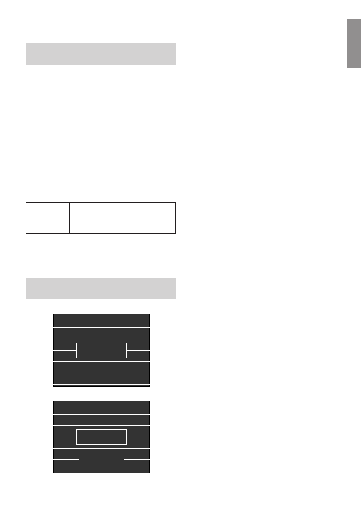
SVD 800 HD
5.12How to reset the adjustments
(RESET)
Note:
Resetting means setting all adjustment values at
50 that corresponds to zero. Starting from this value
you can adjust up to 100 or down to 0.
To reset adjustments read the following instructions
carefully.
If you press the RESET button when you are in the
convergence setups (CONV), you will reset the
convergence parameters and those of the zones of the
three colours R.G.B..
If you press the RESET button when you are in the ZONE
setups, you will reset the zone parameters of the three
colours R.G.B.
The following table shows which parameters are reset
and in which menus.
RESET RESET PARAMETERS COLOURS
CONV
ZONE ZONE ALL
CONVERGENCE AND ZONE
ALL
ENGLISHENGLISH
ENGLISHENGLISH
ENGLISH
N.B.:
After RESET, you can recall the previous values by
loading the current bank from the MEMORY MA-
NAGER (LOAD), if the MEMO procedure has not
been carried out.
5.13 How to store the convergence
adjustments (MEMO)
Press MEMO, the following will appear:
PHASE
CRT = R G B
MEMORIZE ALL DATA
BANK XX XXK-XXHZ
H. VALUE = XX
Fig. 117
press ENTER, the following will appear:
PHASE
CRT = R G B
ALL DATA MEMORIZE
ON BANK XX XXK-XXHZ
H. VALUE = XX
Fig. 118
Storing has now been completed on the current memory
bank. Press ESC to exit.
35
Page 37

SVD 800 HD
6 TECHNICAL SPECIFICATIONS
6.1 Optical data
Projection system
- 3 projection tubes, 3 lenses
- Horizontal line system
6.2 Projection tube
- 7” monochrome tube, high brightness, liquid cooling,
air lens coupling, electrostatic focusing.
- The external red and blue tubes are mechanically
rotated.
6.3 Projection lenses
- High performance hybrid lenses
- Focal length is 135mm, number-f F/1.03 to infinity
- Focus adjustments: centre and borders
- Magnifying power: from 10x to 60x
- Resolution: more than 10 lp/mm at 50% MTF
6.8 Automatic cut off
- The projector automatically carries out controls for
better colour temperature stability at set intervals.
6.9 Adjustments
- All projector adjustments, except for mechanical
centering and focusing, can be done with the remote
control.
6.10 Picture adjustments
- Contrast-brightness-colour saturation (only for
standard PAL, SECAM, NTSC 4.43, NTSC 3.58)
- Hue (only for NTSC 4.43 and NTSC 3.58)
- Peaking
6.11 Geometric adjustments
- Size - Centering - Linearity - Skew - Bow - Keystone Pincushion - Borders, Quarters, Corners.
6.12 Inner test patterns
6.4 Projected picture size
- 60-300 inches diagonally
- Factory set at 90 inches
- Convergence type: by remote control with zone
adjustments
6.5 Brightness
- High brightness in output (100% white):
- 160 lumen ANSI (900 lumen at white peak).
6.6 Video resolution
- RGB input: 1280x1024 pixels
- VIDEO input: 800 TV lines
- HDTV input: 1080 TV lines
6.7 Colour temperature
- 3200,6500,9300 Kelvin degrees, user memory, plus
personal memory on all banks.
- Colour temperature can be selected and adjusted by
remote control.
- The projector is factory set at 6500°K.
- Crosshatch 18x13 - H characters - Dots - Cross Crosshatch 9x7 - White field - White window - Colour
bars.
6.13 Global adjustments and
selections
- Window
- Dynamic H and V focus adjustment
- White balance adjustment
- Signal phase adjustment
- Selectable installation type
- Memory manager
- All parameters can be stored in 30 different labelled
configurations.
- Load, copy, shift and delete functions of the memory
banks.
- On-screen information, recallable by remote control
or a button on the rear panel.
- On-screen display of the ON/OFF commands (only for
contrast, brightness, saturation, peaking and hue).
- No. 10 different ceiling presetting configurations are
available for copying.
36
Page 38

SVD 800 HD
7 DISPLAY PERFORMANCE
7.1 Flyback time
- Horizontal 2.4 µs typ.
- Vertical 150 µs typ.
- R,G,B video bandwidth: 75MHz, -3dB typical
- Standard video bandwidth: 5.5Mhz, -3dB tipical
- Warm up time (suggested): 10 minutes
7.2 Synchronisation
- Horizontal frequency range:15/72 Khz - automatic
hook-up
- Vertical frequency range:45 to 150Hz - automatic
hook-up
7.3 Full function remote control mod.
RC 3000
Operating mode:
- 1.- wired (using the 8 m/24ft cable supplied)
- 2.- wireless (max operating distance: 10m/30ft)
7.4 User remote control mod.
RC3100
Operating mode:
Wireless (max operating distance:10m/30ft)
Functions:
All adjustments can be modified using the remote control,
some can be directly accessed with a key:
- Turning ON/OFF
- Still frame (freeze)
- Format selection
- Picture muting
- VCR sync filter
- Storable picture adjustments
- Normalised values recall
- Picture adjustment
- Video menu
- Projector status info
- Video input selection
- Options
ENGLISHENGLISH
ENGLISHENGLISH
ENGLISH
Functions:
All adjustments can be done using the remote control but
the following can be directly accessed with a key:
- Switching ON/OFF
- Picture muting
- Still frame (freeze)
- Aspect ratio selection
- Single RGB tube power off
- VCR sync filter
- Normalised parameters
- Storable picture adjustments
- Picture adjustments
- Convergence deflection adjustment (installation mode)
- Zone adjustments (installation mode)
- Projector status info
- Video input selection
- Resettable adjustments (installation mode)
- Back lighting by pressing a dedicated button
- If no button is pressed, the light stays on for 20 seconds
more.
- By pressing any button the counter is reset
7.5 Keyboard on the rear panel
Funtions:
- Switching ON
- Input selection
- Picture adjustment
- Info menu
7.6 BNC RGB inputs
BNC connectors:
- R/Cr input 0.7 Vpp, 75 Ohm termination
- G input 0.7 Vpp, 75 Ohm termination, G with synchro/
Y: 1Vpp, 75 Ohm termination, G with synchro / Y: 1Upp,
750 Ohm termination negative synchro.
- B/Cb input 0.7 Vpp, 75 Ohm termination
- RGB video band: 75Mhz, -3dB
- Y Cr Cb band: 40Mhz - 3dB
37
Page 39

SVD 800 HD
7.7 Input synchro
H, H/V sync 75 Ohm termination
a) Horizontal sync or composite sync 0.3-5Vpp, positive
or negative
b) Vertical sync: 0.3-5Vpp, positive or negative
7.9 Video inputs
CVBS 1 BNC composite video input connector, 1Vpp, 75
Ohm termination, negative sync.
CVBS 2 BNC connector, same levels as CVBS 1, 75
Ohm termination, negative sync.
S-VHS 1 4-pin MINI DIN connector, Y brightness signal,
1Vpp, 75 Ohm termination, negative sync.
C: chrominance signal
0.286 Vpp, NTSC 4.43,
NTSC 3.58 (burst level)
0.3 Vpp, PAL,
0.3 Vpp, SECAM
S-VHS 2 same levels as S-VHS 1, 75 Ohm termination,
negative sync
Video input bandwidth 5.5 MHz-3dB
Standards, PAL, SECAM, NTSC 3.58, NTSC 4.43 with
automatic switching
In the case of a bad input signal the standard can be forced
by remote control.
- C.T.I. always active
- Peaking control
- Comb filter on/off selection.
- Luminance/Chrominance delay adjustment
- NTSC: hue adjustment
8 ELECTRICAL DATA
Input: 500W max (12W on stand-by)
Voltage: 120-240Vac 50-60Hz with power
factor correction
Fuse: 10A TH
9 Mechanical data
Dimensions:
Width 620 mm / 24.4 inches
Height 340 mm / 13.38 inches
Depth 700 mm / 27 inches
Weight:
48.5 Kg / 77 lbs net
Packagng:
Reinforced cardboard, filled with anti-shock material and
4 handles for transportation
Packaging dimensions:
Width 806 mm / 31.73 inches
Height 515 mm / 20.27 inches
Depth 886 mm / 34.88 inches
10 TEMPERATURE AND HUMIDITY RANGE
Working from 0 to +35°C
Humidity from 10 to 90% not condensed.
Transportation and deposit -10 to +55°C
11 OPTIONAL ACCESSORIES
UPC
7.10 VGA connector
- D-sub 15 Pin connector
- R,G,B analogue input levels, 0.7 Vpp,75 Ohm
termination
- TTL LEVEL sync input level, positive or negative
- 75 Mhz -3dB video bandwidth
7.11 PC control
Through the RS422 interface the projector can be
controlled by a PC with specific software.
PC connector: D-sub. 9 Pin
This input is compatible with the majority of computers
like IBM, VGA, etc...
12 STANDARD ACCESSORIES
AC power cable (Europe, UK, USA-Canada)
Plastic lens caps
Lens spacers
RC-3000 full-function remote control with batteries
RC-3100 remote control with batteries
Remote control cable (8m)
Ceiling assembly kit
User and installation manual
38
Page 40
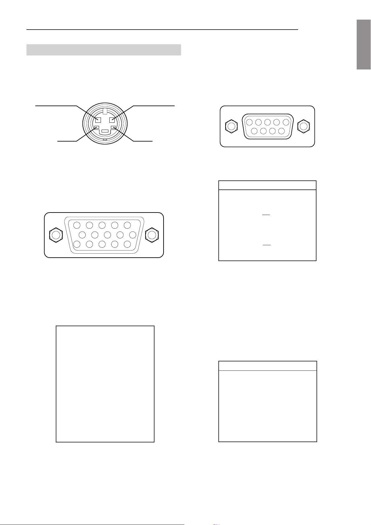
SVD 800 HD
13 PIN ASSIGNMENT
S VIDEO connector (4pin, mini-DIN)
GND
VGA input
DB-15 female connector
54321
109876
15 14 13 12 11
LuminanceCrominance
GND
RS-422A connector (female 9 pin D-sub)
54321
9876
No. pin Signal
1 GND
2 Not used
3 Not used
4TX
5TX
6 Do not use
7 Not used
8RX
9RX
ENGLISHENGLISH
ENGLISHENGLISH
ENGLISH
1 Red
2 Green
3 Blue
4 Not used
5 Not used
6 GND
7 GND
8 GND
9 Not used
10 GND
11 Not used
12 Not used
13 H / HV
14 V
15 Not used
RS 232 compatible connector (only for short distances)
No. pin Signal
1 GND
2 Not used
3 Not used
4TX
5 Do not use
6RX
7 Not used
8 Do not use
9 Do not use
39
Page 41
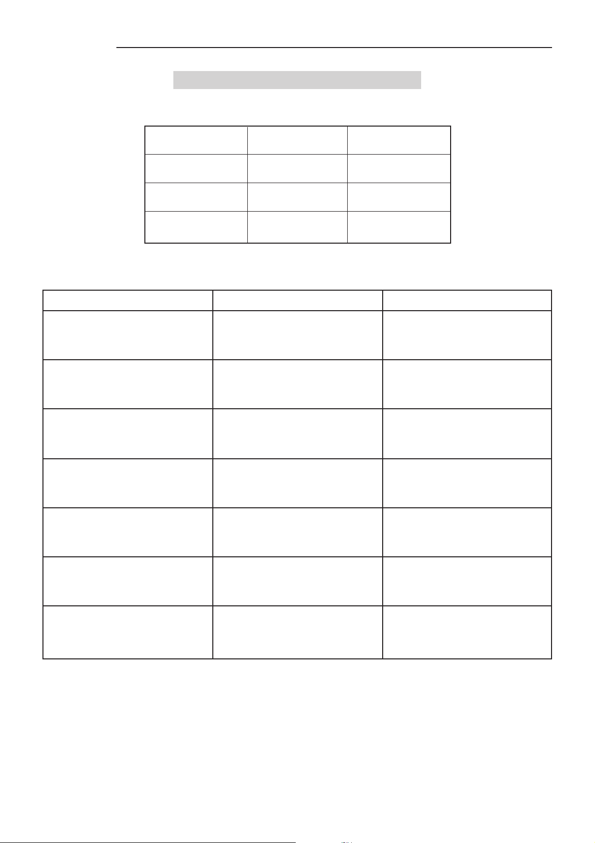
SVD 800 HD
14 TROUBLESHOOTING
The pilot lights on the rear panel show the projector status.
PILOT LIGHT MEANING
ON indicator Red light Stand-by mode
Green light Normal operation
Remote control
indicator
In case of mulfunctioning check the following table before asking for service help.
PROBLEM
The ON push button has not been
The projector will not turn on
No picture is displayed on the screen
The picture is not properly displayed
on the screen
The message Fan Protection
Detected switch off in 06 seconds
appears on the screen
The power cable is disconnected
The projector is switched off
One or more fans have stopped
Blincking light
CAUSES
pressed
The input setting is wrong
The picture setup is wrong
The projector is receiving
commands from the
remote control
Press the ON button
Connect the power cable
If the LED is red it means the
projector is on stand-by. Press a
numerical key to switch it on.
Ref. INPUT SELECTION
Ref. PICTURE ADJUSTMENT
Check that the cooling fan ventilation
holes are not clogged
REMEDY
The message ERROR ON 12C-bus
board xxx device xxx
appears on the screen
The message Convergence
Overload Switch-Off in xxx seconds
appears on the screen
During normal operation the projector
switches off
A communication error has been
detected
Overcurrent has been detected
on the convergence board
The projector is in the
PROTECTION MODE
Switch the projector off and then back
on again. If the message persists
contact a qualified technician
Reset the current memory bank and
repeat installation.
If the message persists contact a
qualified technician
Ask for service
40
Page 42
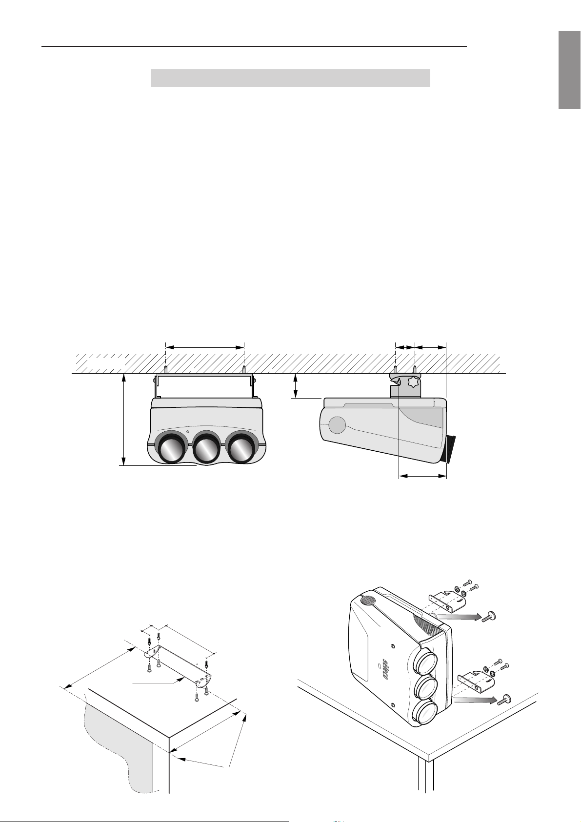
SVD 800 HD
15 FRENCH INSTRUCTION
15.1 Procedure d’installation au
plafond
ATTENTION:
SIM 2 Multimedia décline toute responsabilité pour
les dommages matériels et humains causés par une
installation mécanique, au plafond, erronée ou
négligée, toutes les opérations doivent être effectuées
par un technicien qualifié.
ATTENTION:
Vérifiez que le projecteur ne glisse pas sur la surface
où il repose.
ATTENTION:
Le plafond doit être suffisament solide pour pouvoir
supporter le poids du projecteur.
440
15.2 Projection frontale avec fixation
du projecteur au plafond
Pour installer le projecteur au plafond, utiliser le kit de
montage pour plafond (fourni avec le projecteur) et suivre
les instructions ci-dessous. Pour fixer le projecteur à un
plafond réalisé avec des blocs de béton ou avec des
briques, effectuer un trou de 12 mm de diamètre et de 65
mm de profondeur à l’aide d’une perceuse. Fixer au
plafond la grande patte de fixation se trouvant dans
l’emballage en utilisant les éléments d’accrochage ainsi
que les vis et les rondelles également fournis dans
l’emballage. Pour cela, UTILISER les trous extérieurs de
la patte et serrer avec un couple maximal de 25 Nm.
ATTENTION:
L’installateur devra vérifier si le mur peut supporter
jusqu’à 4 fois le poids total (patte de fixation, hardware
et partie électronique); l’épaisseur minimale du mur
de support devra être de 10 cm.
93 180
ENGLISHENGLISH
ENGLISHENGLISH
ENGLISH
MUR
550
En cas de murs réalisés avec des blocs de béton ou avec
des briques, ne pas percer les trous nécessaires au
montage dans les joints de mortier. La distance entre les
éléments d’accrochage et la partie libre du mur de support
doit être supérieure à 18 cm. La patte de fixation devra
être fixée très soigneusement.
Fixer au plafond la patte de fixation se trouvant dans
l’emballage avec les quatre vis fournies.
Attention: La patte de fixation doit être solidement fixée
et être absolument parallèle à l’écran.
93
440
115
266
Poser le projecteur sur une table en position verticale (le
mettre sur le côté).
N.B.: Enlever les deux pieds avant.
Enlever les 2 vis ainsi que les 2 rondelles, introduire le
crochet gauche et le fixer en utilisant les mêmes vis et les
mêmes rondelles comme indiqué dans le dessin cidessous. Répéter les mêmes opérations pour le crochet
de droite.
=
ECRAN
PATTE
FRONT
=
RESPECTER LE
PARALLELISME
41
Page 43
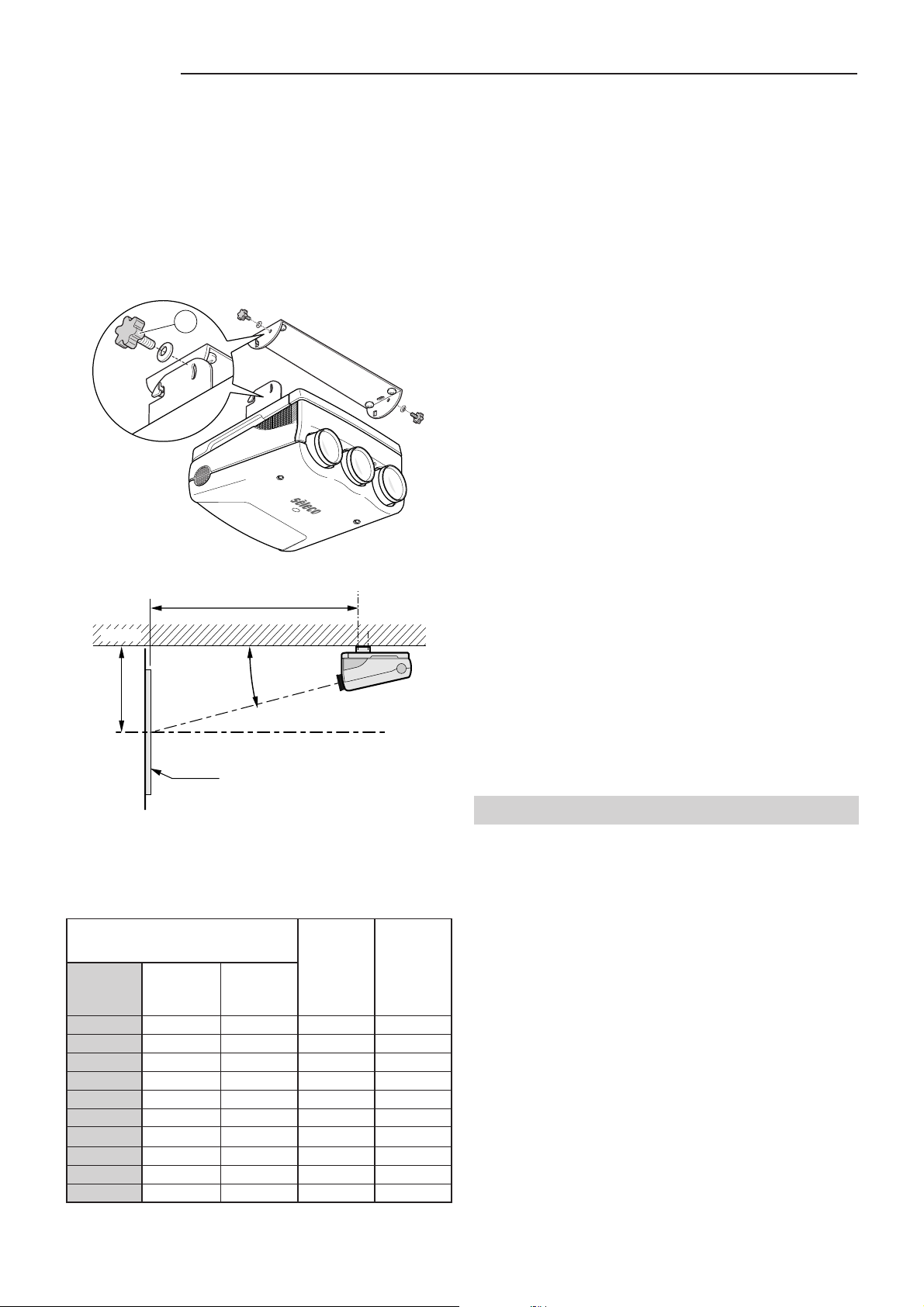
SVD 800 HD
Retourner le projecteur et le fixer au plafond au moyen
des deux crochets.
Incliner le projecteur de manière à centrer l’image verticale et visser les deux vis de fixation (H).
Note: Introduire les rondelles arrondies spéciales entre le
crochet et les vis de fixation. Pour une installation
correctement effectuée, la partie concave de la rondelle
doit être orientée vers la patte de fixation. Pour une
installation faite en toute sécurité, n’utiliser que le kit de
fixation fourni dans l’emballage.
H
FRONT
Note: l’inclinaison entre le plan du projecteur et l’axe des
verres doit être de 14°.
D
MUR
15.3 Projection par l’arrière avec
fixation du projecteur au plafond
L’installation pour la projection par l’arrière peut être
effectuée en accrochant le projecteur au plafond et en
suivant les instructions pour l’installation frontale.
L’utilisation des écartements corrects tels que montrés sur la
table d’écartements, assure une parfaite uniformité de la
convergence de la lumière. La rétro-installation peut-être faite
en accrochant le projecteur au plafond. Dans ce cas, le
projecteur doit être positionné en se référant en même temps
à l’installation au plafond et à la rètro-installation.
Attention:
veuillez lire soigneusement et entièrement cette notice.
Elle vous fournira les informations de base pour
l’utilisation du projecteur. Installation, réglages et
procédures préliminaires qui requiérent l’ouverture du
projecteur et le contact avec les composant électrique
doivent être exécutées par le personnel de service. Pour
préserver votre sécurité et réaliser des opérations fiables,
utilisez seulement les câbles d’alimentation fournis par le
fabricant. Conformez vous à toutes les instructions et à
toutes les mises en garde.
Avant de mettre en marche le projecteur,
15.4 Selection du voltage et cable
d’alimentation
Le projecteur fonctionne avec une alimentation en 120-240
VAC, 50/60Hz, 500W, 4,2A RMS-MAX comme indiqué sur
l’étiquette arriére.
E
14°
CENTRE DE L'ECRAN
ECRAN
TABLEAU 3: PROJECTION FRONTALE AVEC
FIXATION DU PROJECTEUR AU PLAFOND
D = Distance entre la ligne du premier trou de la patte
de fixation et l’écran.
E = Distance entre le plafond et le centre de l’écran.
GRANDEUR ECRAN D E
Aire utile 4/3
Diagonale Largeur Hauteur
(pouces) (cm.) (cm.) (cm.) (cm.)
60” 121,9 91,4 204 81
80” 162,5 121,9 258 95
90” 182,9 137,2 284 104
100” 203,2 152,4 312 109
120” 243,8 182,9 366 125
150” 304,8 228,6 447 146
180” 365,7 274,3 528 167
200” 406,4 304,8 582 181
250” 508,0 381,0 718 217
300” 609,6 457,2 853 251
Nota:
Pour des écrans format 16/9, mesurer la largeur
et se référer à la largeur du tableau la plus
proche.
15.5 Cet equipement doit être mis a
la terre
Si la prise de courant de l’alimentation n’est pas équipée
d’une fiche de terre, applez votre électricien et munissez vous
d’une ligne d’alimentation avec prise de terre et assurez vous
de son efficience.
16 GERMAN INSTRUCTIONS
ACHTUNG: ÖFFNEN SIE NICHT UND NEHMEN SIE
NIEMALS DIE HAUBE DES PROJEKTORS AB WEIL
DARUNTER GEFAHRLICHE HOCHSPANNUNGEN, BIS 33
KVOLT, ANLIEGEN. WENN ERFORDERLICH, RUFEN SIE
IMMER EINEN TECHNIKER.
SIM 2 Multimedia lehnt jejliche Verantwortung ab, für
Schaden an Personen und Sachen, die durch Nichtbeachtung
dieser Anweisung und der anderen, die in dieser
Bedienungsanletung enthalten sind, entstehen können.
16.1Hinweis gemäß behördlicher
Vorschriften
Die in diesem Gerät entstehende Röntgenstrahlung ist
ausreichend abgeschirmt.
Beschleunigungsspannung maximal 33,5 KVolt.
Unsachgemässe Eingriffe, insbesondere Veränderungen der
Hochspannung oder Auswechseln der Projektionsröhren,
können dazu führen, daß Röntgenstrahlen in verstärktem
Ausmasse auftreten.
Ein so verändertes Gerät entspricht nicht mehr der Zulassung
und darf infolgedessen nicht mehr betrieben werden.
42
Page 44

 Loading...