

Page 1
HT5000HB - PRO5DL
user and installation manual
460637000
Page 2
ht5000HB - pro5dl
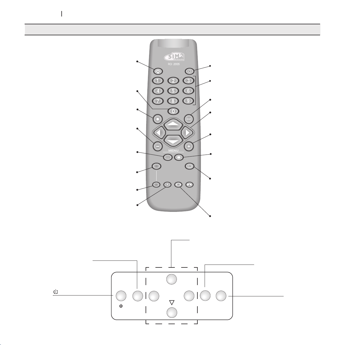
REMOTE CONTROL AND KEYPAD
LIGHT
F1
ZOOM
FOCUS
F2
MENU ESC SOURCE
◀
▲
▼
▶
Backlights the keys on the remote control.
BACKLIGHTING
INPUT
Displays input selection menu.
Places the projector in standby mode.
Access the following functions:
Test Pattern - Zoom - Focus
MENU -
Opens the On Screen Display menus and permits
browsing though the various pages.
FREEZE
Freezes/unfreezes a moving picture.
ZOOM
Selects lens zoom adjustment.
Function Key F1
FOCUS
Sets the lens focus.
Function Key F2
AUTO
Automatically optimises the projected image.
Standby / ON
Places the projector in standby mode.
KEYS 0-9
Selects the sources directly.
Switches the panel on from Standby.
ESCAPE
Disables the On Screen Display.
UP/DOWN/LEFT/RIGHT ARROW KEYS
Lets you browse through the On Screen Display menus
and parameter settings. Up/Down arrows open the
quick menus.
MENU +
Switches on the On Screen Display and browses through
its pages.
MEMORIES
Activate the memory management menu.
INFO
Displays information on the selected source and
projector status.
ASPECT
Selects the image Aspect ratio.
Places the unit in
2
standby mode.
Opens the On Screen Display
menus and permits browsing
though the various pages.
▲,▼,◀,▶
Browse through the On Screen Display
menus and set parameters.
Disables the On Screen Display
Opens the Input
Selection menu.
Page 3
ht5000HB - pro5dl
1 INTRODUCTION
FULL HD
1920x1080
The HT5000HB - PRO5DL projector uses the maximum in signal processing technology as well as the innovative DLP™ and a refined
optical system.
Its range of inputs (1 Composite Video inputs, 1 S-Video inputs, 2
Component or RGB inputs (4 RCA connectors and 5 BNC connectors), 2 graphic RGB inputs, 6 HDMI™ inputs, 1 SDI input, 1 DVI-D input)
allow it to be connected to a wide range of analogue and digital
sources: DVD players, video recorders, satellite and terrestrial receivers,
computers, video game consoles, camcorders, etc.
Its image processing system permits optimum reproduction of a wide
range of input signals, from interlaced video to high definition and
digital graphics.
Faithful reproduction of signals at higher resolutions (such as high
definition video and graphics) occurs without loss of information or
reduction of image sharpness thanks to the processor’s high pixel rate
signal acquisition capabilities.
CONTENTS
1 PRESENTATION 3
2 SAFETY WARNINGS 4
3 UNPACK ING 7
4 INSTALLATION 8
5 START-UP AND SHUTDOWN 10
6 CONNECTIONS 10
7 REMOTE CONTROL 14
8 ON SCREEN MENU 15
Different input signal resolutions can be adapted to match the specified
screen resolution without loss of image quality, thanks to a generous
selection of default aspect ratios, some of which are user definable.
All picture adjustments can be made with the remote control interacting with a simple menu-activated On Screen Display; alternatively, the
projector can be controlled by a home automation system through its
serial port , the 1.1 USB port, an RS232 serial port or the RJ45 Ethernet
port.
The appliance has been subjected to exhaustive operating tests by
SIM2 to guarantee the highest quality.
The projector bulb life should thus initially be around 30-60 hours.
In addition to the customary checks, the Quality Control department
also runs additional statistical tests before shipment.
In such cases, the packaging may show signs of having been
opened, and the hours of lamp operation may prove to be
higher than those normally shown when only standard tests are
performed.
9 CLEANING AND MAINTENANCE 26
10 MOST FREQUENT PROBLEMS 26
11 OPTIONAL ACCESSORIES 27
TECHNICAL SPECIFICATIONS 28
Structure of the on screen menu 29
Dimensions 31
Horizontal/vertical shift - Tilt 32
Projection distances 33
Technical service 34
DLP and DMD are registered Texas Instruments trademarks.
HDMI, the HDMI logo and the expression High-Definition Multimedia Interface
are trade marks or registered marks of HDMI licensing LLC
3
Page 4
ht5000HB - pro5dl
2 SAFETY WARNINGS
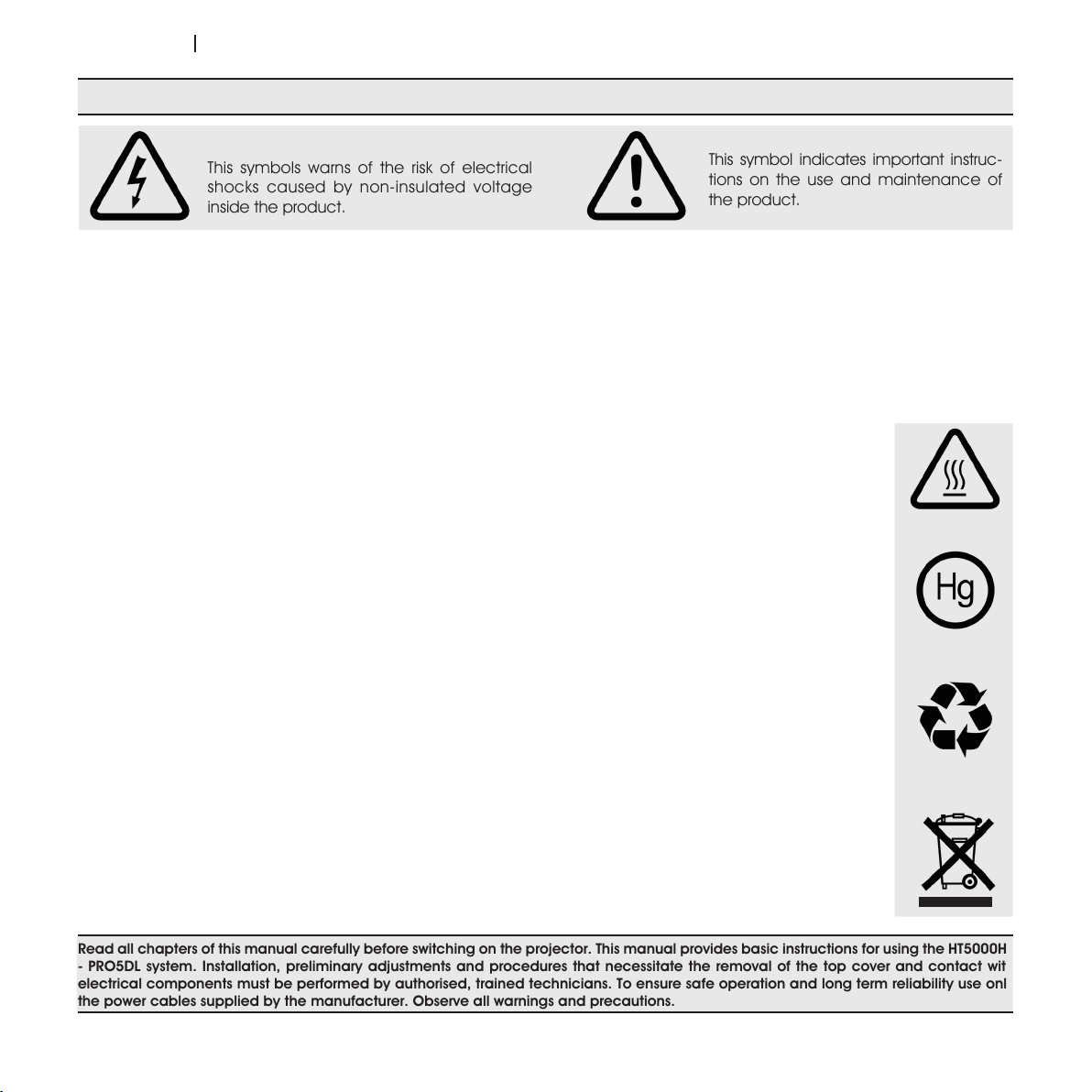
This symbols warns of the risk of electrical
shocks caused by non-insulated voltage
inside the product.
This symbol indicates important instruc-
tions on the use and maintenance of
the product.
CAUTION
To reduce the risk of electrocution, disconnect the power supply cable on the rear panel before removing the top cover of the projector.
For technical service refer to trained personnel authorised by the manufacturer.
LAMP WARNING
If the lamp suddenly explodes with a loud bang, air the room thoroughly before using it.
Do not attempt to replace the bulb: contact your local service centre for the replacement.
ENVIRONMENTAL INFORMATION
This product contains materials derived from natural resources during its manufacture. It may contain materials which
constitute a health and environmental hazard. To prevent harmful materials from being released into the environment and
to promote the use of natural materials, SIM2 Multimedia provides the following information regarding the disposal and recycling of the product. Waste electrical and electronic materials (WEE) should never be disposed of in normal urban waste
disposal facilities. The label on the product, shown here, indicating a cancelled garbage can, is intended to remind you
that the product requires special handling at the end of its service life.
Materials such as glass, plastic and some chemical compounds are recoverable and can be recycled for reuse. Please
observe the following instructions:
1. When you no longer wish to use your electrical and electronic equipment, take it to your local waste disposal facility
for recycling.
2. You may return your old equipment to your dealer free of charge when you buy a new product which is equivalent
or has the same functions as the old one. Call SIM2 Multimedia to find your local dealer.
3. If you need more information regarding recycling, reuse and product exchanges, please contact customer service
at the number given in the manual.
Lastly we suggest further measures to safeguard the environment, such as recycling of internal and external packaging
(including that used for shipping) in which the product was delivered. With your help, we can reduce the amount of environmental resources required to make electric and electronic equipment, reduce the use of waste tips for used equipment
and, in general, improve our quality of life by making sure that hazardous materials are correctly scrapped.
Incorrect treatment of the product at the end of its service life and failure to follows the above disposal instructions are
punishable under local legislation.
Read all chapters of this manual carefully before switching on the projector. This manual provides basic instructions for using the HT5000HB
- PRO5DL system. Installation, preliminary adjustments and procedures that necessitate the removal of the top cover and contact with
electrical components must be performed by authorised, trained technicians. To ensure safe operation and long term reliability use only
the power cables supplied by the manufacturer. Observe all warnings and precautions.
4
Page 5
ht5000HB - pro5dl
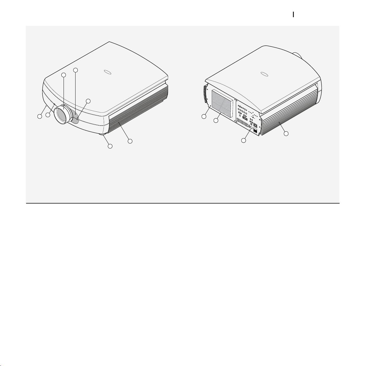
1 Projection objective lens.
1
2
3
4
5
6
5
7
10
8
9
2 Door for changing lens.
3 Front receiver for infrared remote control.
4 Objective lens release hole.
5 Height-adjustable support feet.
6 Ventilation grille for air intake.
7 Access compartment for changing bulb.
8 Connection panel
9 Ventilation grille for air outlet.
10 Ventilation grille for air outlet.
• Read this manual carefully.
This manual contains important information on how to
install and use this equipment correctly. Before using the
equipment, read the safety prescriptions and instructions
carefully. Keep the manual for future consultation.
• Do not touch internal parts of the units.
Inside the housing there are electrical parts carrying
dangerously high voltages and parts operating at high
temperature. Never open the housing. Entrust all servicing
and repair work to an authorised Service Centre. Opening
the housing voids the warranty.
• Disconnecting the appliance from the power supply.
The device which disconnects the unit from the mains is
the power plug. Ensure that the power cable plugs and
the electrical mains socket outlets are easily accessible
during installation operations. Pull the plug, not the cable,
to disconnect the unit from the mains.
• Use only the specified power supply.
Connect the units to a mains electrical supply with rated
voltage of between 110-240 VAC, 50/60 Hz and equipped
with a protective earth connection. If you are not sure of
your domestic mains rating, contact an electrician. Take
care to avoid overloading the power socket and any extension leads.
• Changing the fuses.
Before changing the fuse, disconnect the unit from the
mains power supply.
The fuse compartment is next to the power supply connec-
tor. Remove the fuse holder with a flat head screwdriver
and replace the fuse. Fit the replacement fuse. Use only
type T 10A H fuses.
5
Page 6

ht5000HB - pro5dl
• Be careful with cables.
Make certain cables are routed so that people will not be
impeded or tripped up.
Keep all cables away from children.
Install the unit as close to the wall socket as possible.
Avoid stepping on power cables, make certain they do
not become tangled, and never jerk or tug them; do not
expose them to sources of heat, and make sure they do
not become knotted or crimped. If the power cables be-
come damaged, stop using the system and request the
assistance of an authorised technician.
• Disconnect the unit from the mains power during electrical
storms and when not in use.
To prevent damage from lightning strikes in the vicinity,
disconnect the unit during storms or when the system is
going to be left unused for a long time.
• Avoid contact with liquids and exposure to damp.
Do not use the unit near water (sinks, tubs, etc.); do not
place objects containing liquids on or near the units and do
not expose them to rain, humidity, drops of water or sprays;
do not use water or liquid detergent to clean them.
• Do not allow the units to overheat.
To prevent overheating, allow a free space of at least 40
cm at the back of the projector.
Do not obstruct the ventilation slots.
Do not place the unit near heat sources such as heaters,
radiators or other devices (including amplifiers) that gener-
ate heat.
Do not place the unit in an area where there is insufficient
space (shelving units, bookshelves, etc.) and in general
avoid placing it in poorly ventilated areas as this may
prevent sufficient cooling.
• Place the unit on a stable surface.
Place the projector on a stable surface or use the ceiling
mounting bracket provided.
Never place the projector on its side or rear, on the lens or
top panel.
• Do not insert objects through the openings in the unit.
Make sure that no objects are inserted inside the units. If this
should occur, disconnect the unit from the power supply
immediately and call an authorised technician.
• Power saving.
We advise disconnecting the unit from the power supply
when not in use. In this way you will achieve considerable
power savings while at the same time protecting internal
electrical parts from wear.
• Hight Altitude.
During the installation, when using the projector over 3000
feet above sea level, set the “ALTITUDE” to “HIGH” from the
Service menu. Otherwise the life of the product may be
shortened.
• PRODUCT DISPOSAL
This projector is fitted with a pressurised lamp containing
a small amount of mercury. These lamps may be subject
to special disposal regulations due to environmental considerations. For disposal or recycling information, please
contact your local authorities or, if you are located in the
USA, the Electronic Industries Alliance.
www.eiae.org
www.lamprecycle.org
• Never look directly at the projection lamp.
Never look directly at the objective lens when it is on as the
intense light may damage your eyes. Take particular care
that children cannot do so.
• Take special care regarding movement of the lens.
Do not place objects in the slots on the side of the lens, and
also ensure that horizontal and vertical lens movements
are not impeded by external objects.
6
Page 7
ht5000HB - pro5dl
3 UNPACKING
Instuction’s manual
Remote Control
4 Batteries AAA 1.5V
Power Cables
Projector
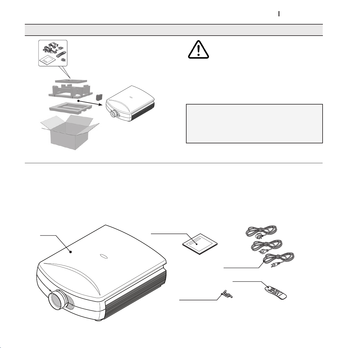
CONTENTS OF THE PACKAGE
- projector
- remote control
- Four 1.5V AAA type batteries for the remote control
- network cables for the projector
- instruction booklet.
For easy extraction of the HT5000HB - PRO5DL system
from its cardboard box, follow the instructions shown
here (Fig.1).
Due to the weight of the equipment, it should be
unpacked by two persons.
1.2.Extract the cardboard structure that contains the
instructions manual and the connection cables.
Lift the projector, grasping it by the indentation on
the side profiles.
Fig.1
If any of the accessories are missing, please contact your dealer as soon as possible.
7
Page 8
ht5000HB - pro5dl
ZOOM
ZOOM
ZOOM
ZOOM
F1
FOCUS AUTO ASPECT VCR
HELPZOOM
F2
ZOOM
FOCUS
FOCUS
FOCUS
FOCUS
4 INSTALLATION
Place the projector on a stable surface or use the optional
ceiling bracket.
WARNING: When using the ceiling mount bracket, the safety
instructions provided with the bracket must be strictly observed. If you use a bracket other than the one provided by
SIM2 Multimedia, make sure the projector is located at least
65 mm from the ceiling and that the bracket does not block
the air intake and outlet slots.
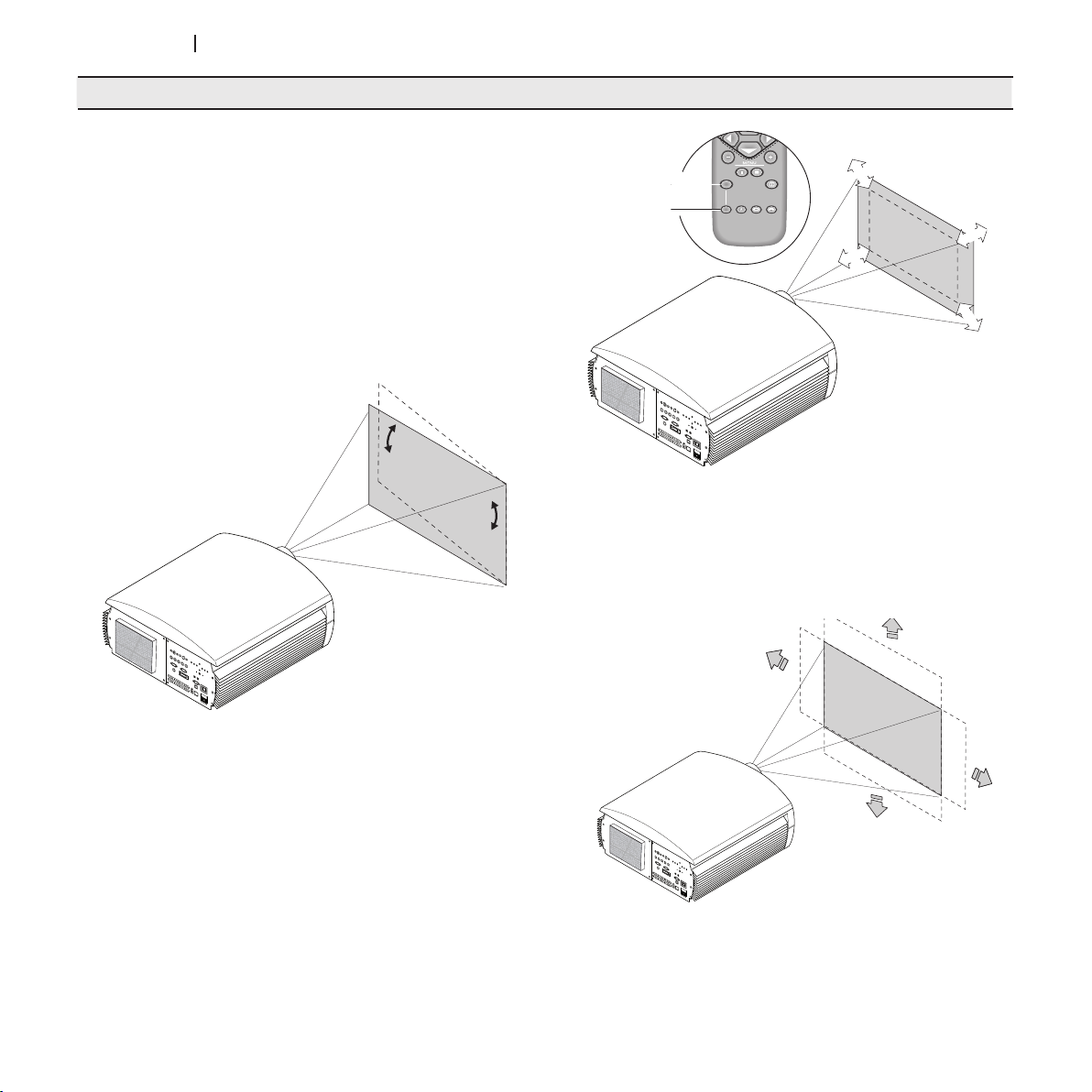
If the image slopes left or right, adjust the two feet on the bottom
to obtain a level position, lining up the base of the projected
image with the base of the projection screen (Fig. 2).
Fig.3
The image can be centred using the motorized lens control.
Movements can be either vertical or horizontal (Fig.3a).
Placed the projector at the desired distance from the screen:
the size of the projected image depends upon the distance
between the lens and the screen and the zoom setting.
Use the motorized zoom (Fig. 3) widen or to narrow the projected image.
Use the motorized focus (Fig. 3) to obtain the best definition of
the projected image. If the focus is correct, from up close to
the screen you should be able to distinguish each single pixel
that makes up the projected image (Fig. 3).
8
Fig.2
Fig. 3a
Page 9
ht5000HB - pro5dl
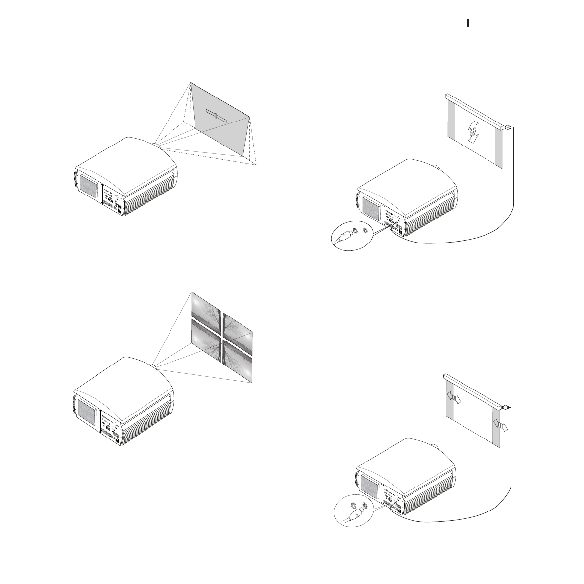
If this movement is not enough, you will need to tilt the projector
KEY STON E
20%
TRIG 1
TRIG 2
TRIG 2TRIG 1
and correct the keystone distortion using the keystone adjustment in the installation manual (Fig.4).
off the projection screen when you change the format of
the projected image (Fig. 7). The activation command can
be provided using output TRIG2 located on the back of the
projector.
Using the Orientation item in the Setup menu, you can either
turn the projected image upside down or create a mirror image
of it (Fig.5), so as to adapt it to the configurations of frontal,
frontal on ceiling, rear, or rear on ceiling installation.
It is possible to use a hideaway motorized screen. The activation switch can be provided using output TRIG1 located on the
back of the projector (Fig. 6).
This output is activated (voltage +12 V DC) when you turn the
projector on. It is de-activated (no output voltage) when the
projector is in standby status.
You can also use black motorized hideaway curtains to mark
Fig. 4
Fig. 6
For rear installations, a suitable translucid screen must be used.
For front installations, it is advisable to use a screen with nonreflective black edges that perfectly fit the projected image.
You should use screen with unity gain. Directional screens with
high gain may be used effectively only for small groups of
spectators located at the centre of the screen.
Do not allow room lighting to shine directly onto the screen
during projection. This would reduce the contrast image.
Keep the projection screen away from furniture or other objects
with reflective surfaces, or light-coloured walls.
Fig. 5
Fig. 7
9
Page 10
ht5000HB - pro5dl
5 START-UP AND SHUTDOWN
I
0
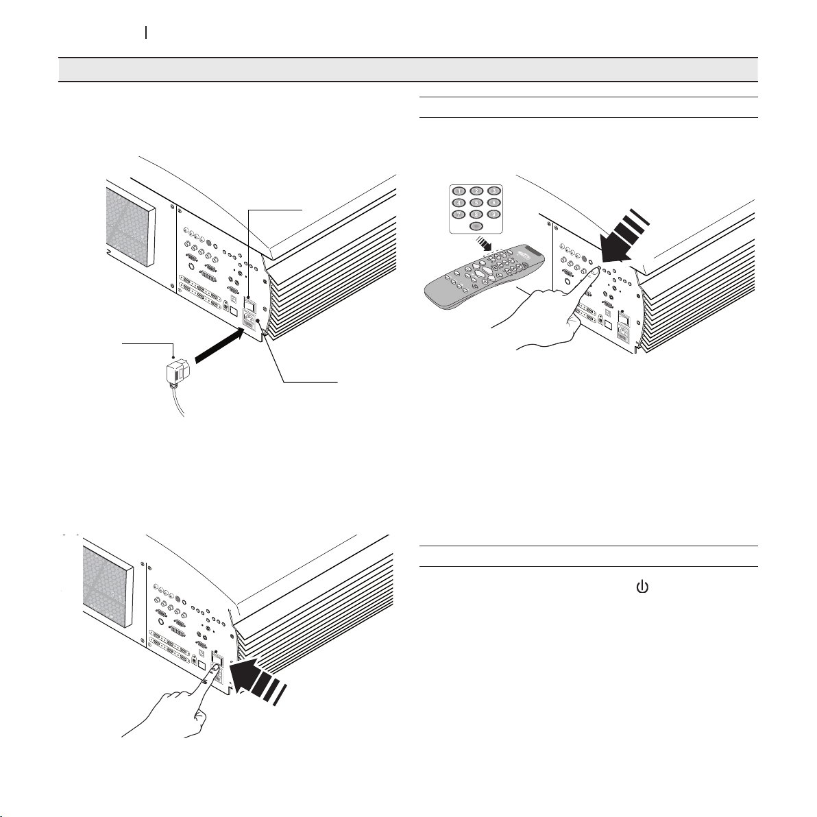
Power Switch:
Position I: On
Position 0: Off
Fused
Power Socket
Power Plug
I
0
I
0
0
ATTENTION: Connect the units to a mains electrical supply
with rated voltage of between 110-240 VAC, 50/60 Hz and
equipped with a protective earth connection (Fig. 8).
Fig. 8
In position I, the projector runs a number of initialization steps
(red and blue lights on), and then it goes into standby status
(red light on) (Fig. 9).
START-UP FROM STANDBY STATUS
From the remote control: press one of the keys 1...9 or 0.
From the keypad: press the on/off key
Fig.10
When starting from standby, the lamp comes on. After a short
warm-up, the image appears (blue light on). The projected
image comes from the input selected at the time of the last
shutdown (Fig. 10).
If too little time has elapsed since the last shutdown, the lamp
may not light if it is too hot.
In this case, you should let the lamp cool off for a few minutes.
10
SHUTDOWN AND RETURN TO STANDBY STATUS
From the remote control: press the key .
From the keypad: press the ON/OFF key
Upon shutdown, the projector reverts to standby status, and
memorizes the input selected at the time of shutdown.
The fans continue to run until the lamp is cool (red and blue
lights on). Then they shut off automatically. Do not turn off the
projector with the network switch until the fans stop running.
Fig. 9
Page 11
ht5000HB - pro5dl
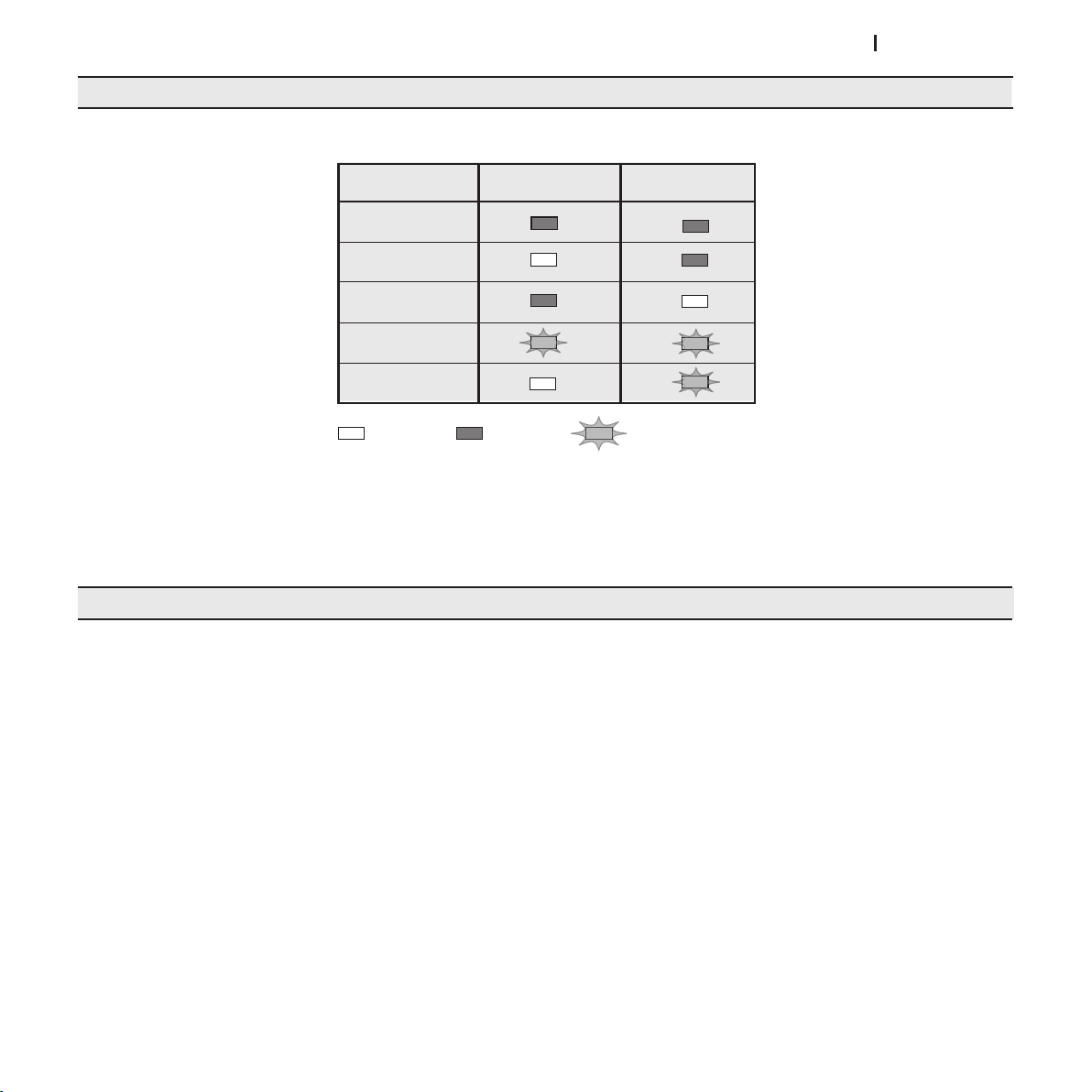
Initialisation
Status
Led blue
Led rosso
Standby
On
Cooling
: O
: On
: Flashing
Error (*)
Logo retroilluminato
Colore Blu
Colore Rosso
Spento / Blu
Colore Rosso
Colore Rosso
TABLE OF LED'S
6 CONNECTIONS
(*):
IF AN ERROR IS INDICATED, CONTACT SIM2 MULTIMEDIA TECHNICAL SERVICE.
Fig.11
To get the most out of the projector, make connections to the
signal sources using quality cables made specifically for video
applications.
Low-quality cables and connectors may corrupt the signals
and degrade the quality of the projected image.
Conserve and use the cables with care. Follow these simple
instructions:
With the exception of RCA type coaxial connectors, always
check the correct direction of insertion of the connectors
in their sockets to prevent deformation of the feet.
When you unplug equipment, do not pull on the cables.
Do not twist or crush the cables.
For temporary installation in dark areas, make sure to
arrange the cables so that persons may move freely.
11
Page 12
ht5000HB - pro5dl
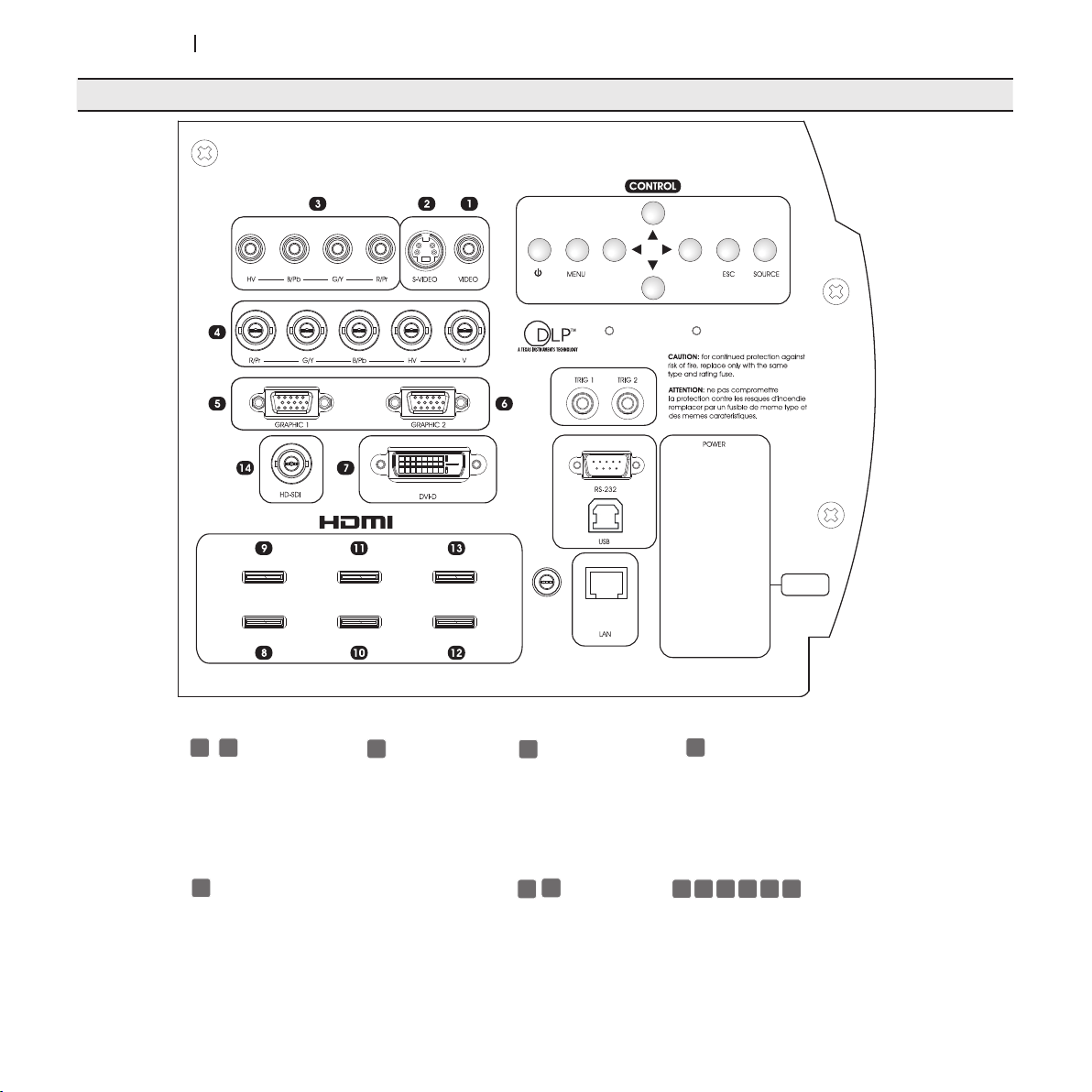
Connection panel
3
1
245
6
LINE INPUT 110-240~
7,6 - 3,4 A
FUSE T10A H 250V
14
7
8 9 10 11 12 13
Television receiver
DVD player
Video recorder
Camcorder
Video game console
Television receiver
HDTV receiver
DVD player
Video recorder
Video game console
12
Television receiver
HDTV receiver
DVD player
Video recorder
Video game console
Blue-Ray player
HD DVD player
HDTV receiver
DVD player
Computer
Computer
Professional and broadcasting equipment
HDTV receiver
DVD player
Video game console
Blue-Ray player
HD DVD player
Page 13
ht5000HB - pro5dl
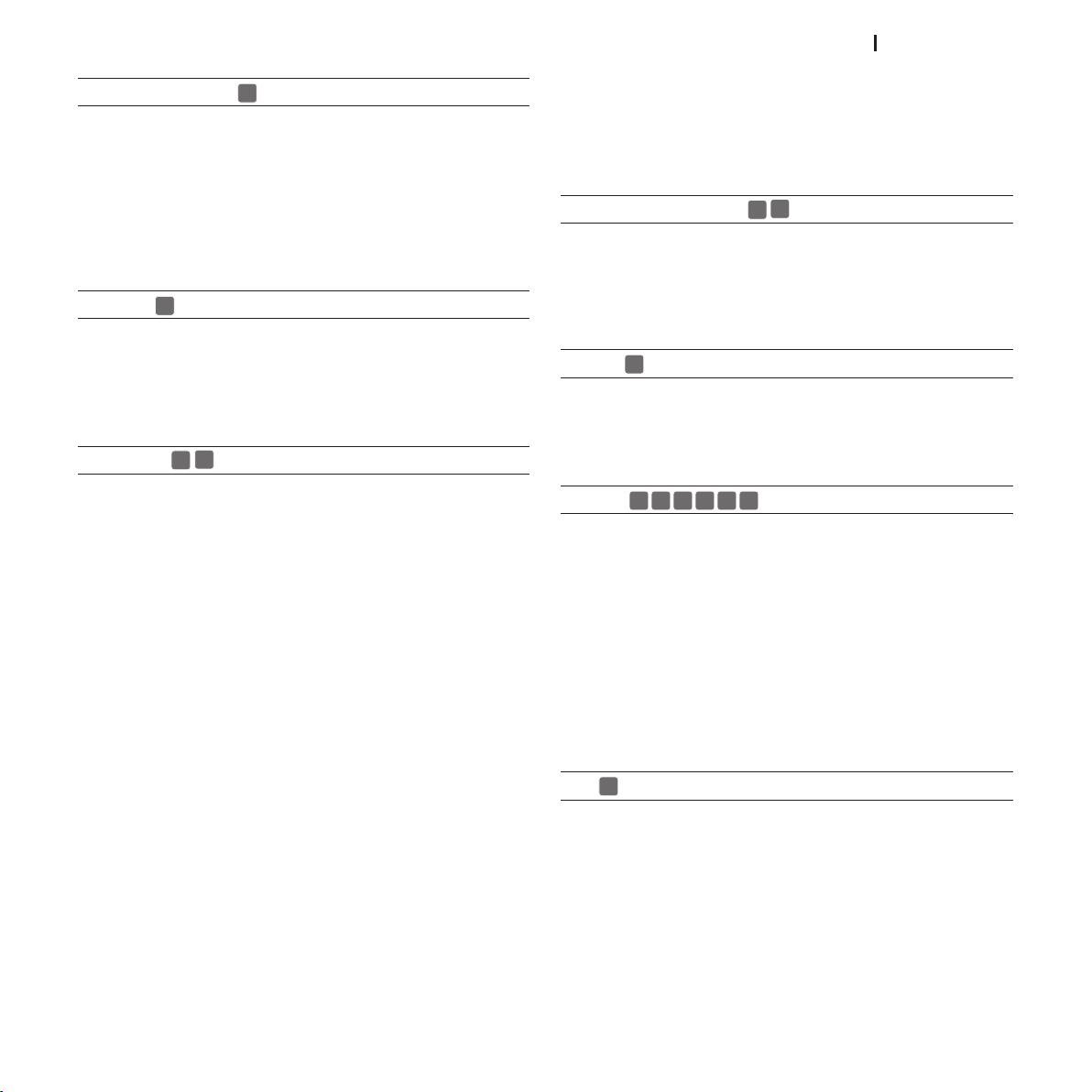
COMPOSITE VIDEO
1
2
3
4
5
6
8 9 10 11 12 13
14
7
Fit an RCA connector with a Composite Video (CVBS) signal
to this input.
The output connector on the external appliance is normally
coloured yellow and will often be labelled VIDEO.
Other signal and socket formats may be preferable (because
they give better image quality), but this type of output socket is
still the most commonly used, and nearly all television receivers,
video recorders, DVD players and camcorders, etc. use it.
S-VIDEO
Fit a mini-DIN connector with an S-Video signal to this input.
The corresponding output on the external device is normally
identified by the labels S-VIDEO or Y/C. This type is nearly as
common as Composite Video, and is preferable to the latter,
since it gives higher image quality.
RGB/YPrPb
interlaced signal outputs it is good practice to compare the
quality of the pictures reproduced by the HT5000HB - PRO5DL in
the two cases: the de-interlacing performed by the HT5000HB
- PRO5DL is often more effective than that performed by the
sources themselves.
GRAPHICS RGB / YPRPB
This input should be connected to an RGB/YPrPb type video or
graphic signal using a cable with a DB15HD type connector. The
signal source device (typically a personal computer or game
console) must be able to provide separate H/V synchronisation
or composite H+V synchronisation.
DVI-D
This input permits you to make the best use of digital image
quality. If your source has a DVI-D output (with YPrPb or RGB signal), connect it to this input to get the most out of the HT5000HB
- PRO5DL system.
These inputs use a set of 4 RCA (3) connectors and 5 BNC (4)
connectors. RGB and Component signals can be applied to
each set of connectors.
If you use the RGB inputs you can select YPrPb video mode.
The RGB signals may have composite synchronisation on the
green signal (RGsB), composite synchronisation on the HV signal and separate synchronisation on the H and V signals via
BNC connectors. Connect the R, G, B outputs of the source to
the respective R, G, B inputs of the HT5000HB - PRO5DL (taking care not to invert the positions) and any synchronisation
signals to the HV. With regard to the 3 sets of RCA connectors,
when hooking up, use the colours of the RCA connectors as
an aid as follows: the R connector is red, G is green, B is blue
and HV is white.
You can use a SCART to RCA adapter cable to connect the
RGB signal from a source equipped with a SCART output to
this input.
The Component signals connect to the Y, Pr and Pb inputs: take
care that the inputs match the outputs on the source device.
As indicated in the table, the colours of the connectors can
also be of help.
Only horizontal scanning frequencies of 15 kHz (standard
video resolution) or 32 kHz or higher (high definition video, with
progressive scanning, high definition video) can be applied
to this input.
Progressive signals usually provide better quality than interlaced
signals, but if the source features both progressive and de-
HDMI™
HDMI (High Definition Multimedia Interface) integrates an uncompressed high definition video signal with a multi-channel
audio signal and allows exchange of control data between
the video source and the HT5000HB - PRO5DL.
The HDMI™ input allows connection to video sources that use
the HDCP (High-Bandwidth Digital Content Protection) protocol
to protect their contents.
Once the video source has been connected to the HDMI™
input, internal processing by the HT5000HB - PRO5DL separates
the video information from the audio information.
You can use a DVI-D > HDMI adapter cable to connect the
DVI-D signal from a source equipped with a DVI-D output.
SDI
The HDSDI/SDI input permits you to connect sources with serial
digital outputs in YPrPb components in compliance with the
SMPTE292M (high definition) and SMPTE259M-C (standard
definition) standards. The signal, of the uncompressed type, is
transmitted digitally by single coaxial cable, thus guaranteeing
a high level of resistance to noise and disturbance.
13
Page 14
ht5000HB - pro5dl
I
0
CONTROL USB
CONTROL RS232
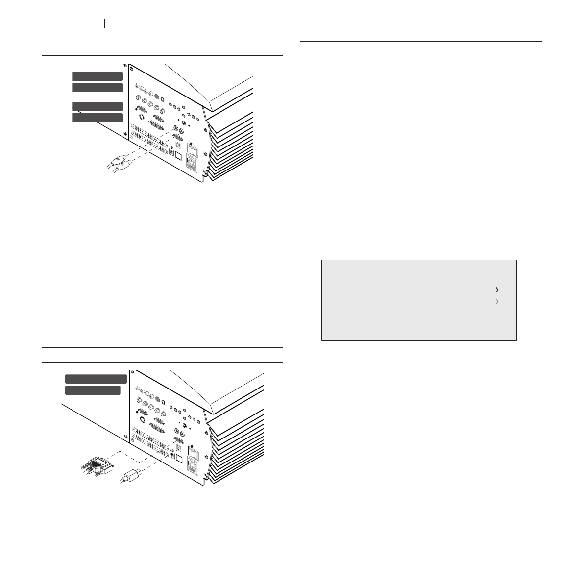
OUTPUTS FOR ACTIVATING MOTORIZED SCREENS
I
0
12 Volt
TRIG 1
TRIG 2
120 mA
Network Setting
IP Configuration
IP: 172.031.127.045 MAC: 00:00:00:00:00:00
Email Configuration
NETWORK FUNCTIONS (RJ45 CONNECTOR)
The HT5000 - PRO5DL projector is equipped with a 10/100 Mbit
Ethernet interface by means of which the projector can be
connected to a LAN or to the Internet.
The network connection can be used to remotely control the
projector from any workstation with access to the network by
sending TCP/IP protocol commands.
Additionally, by suitably configuring the network specifications,
you can receive e-mail notifications on the operating status of
the HT5000 - PRO5DL projector.
Fig. 12
The projector is equipped with two outputs (Voltage: 12 Vdc)
for motorised projection screen and screen masking systems,
used for masking off the projection area to match the projected
image aspect ratio (Fig. 12).
The TRIG1 output is activated when the projector is switched
on (blue LED on) and is de-activated when the projector is in
standby mode (red LED on). The TRIG2 output can be set with
the Screen control adjustment in the Aspect menu. This output
allows reduction of the area of a 16:9 screen, to a 4:3 format,
by activating a horizontal screen masking system output.
RS232 INTERFACE CONNECTOR OR USB INTERFACE
CONFIGURING NETWORK FUNCTIONS BY OSD (NETWORK
SETUP):
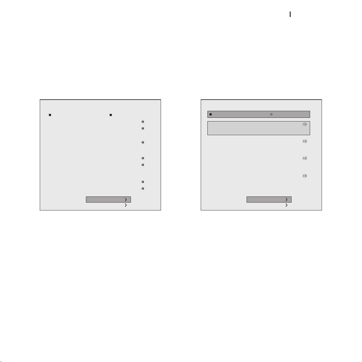
The “Network configuration” option in the “Setup” menu is displayed only when no signal is being displayed (Fig. 14).
Fig. 14
This menu screen permits you to:
access the menu for setting the projector’s network ad-1.
dress
access the menu for entering the e-mail address for receiv-2.
ing notifications on the projector status.
The projector’s current IP address and MAC address (physical
address) are displayed at the bottom of the screen.
You can control a projector from a PC by connecting to this
connector a cable from an RS232 serial port or to a USB port
of a PC (Fig. 13).
14
Fig. 13
N.B. The system is delivered with default factory settings, in
which the dynamic IP address (DHCP) is active. If the network
to which the projector is connected has no DHCP server, the
current IP address displayed on screen may not be valid.
Page 15
ht5000HB - pro5dl
TYPE OF IP ADDRESS
IP Address Mode
Web interface
Remote Control
IP Address: 172.031.127.055
Subnet Mask: 255.255.000.000
Gateway: 172.031.045.115
DHCP Host Name : sim2prj
Port: 08080
Password: XXXX
Port 1: 10001
Port 2: 30704
Static IP Dinamico IP (DHCP)
Apply Settings
Factory Settings
Email Configuration
SMTP Mail Server:
172.031.127.066
Domain Name:
Mail Server:
SMTP Port:
00025
Recipient Address:
Enable Disable
Apply Settings
Factor Settings
This screen permits you to select the type of IP address to be
assigned (Fig. 15):
Static IP: the IP address, network SUBNET and GATEWAY 1.
must be entered manually.
Dynamic IP (DHCP): choose this option if you want the 2.
projector IP address to be automatically assigned by the
network DHCP server (in most networks the DHCP server is
a router).
RESTORING SETTINGS
To restore the projector’s network setting to the default factory
setting click on “Restore”. Wait for completion of the restore
procedure.
EMAIL SETTINGS
This screen is used to define the operating parameters for notification of the projector status by e-mail (Fig. 16).
REMOTE CONTROL
In order to control the projector by TCP/IP protocol, you must
specify the TCP port to which the connection must be made
(called TCP socket). Choose the port number and set “Port 1”.
If you want to establish a connection with the projector via the
Internet, the port chosen for remote connection must be accessible from outside (usually a Virtual Server is created in the
network router to make the projector’s IP address accessible
from a Personal Computer connected to the Internet).
SAVING SETTINGS
Go to “SAVE CHANGES” to enable the chosen setup (wait for
completion of the save procedure).
Fig. 15
Fig. 16
Enabled:• notification service by email is enabled.
Disabled: • notification service by email is disabled.
Domain name, SMTP Mail Server: parameters to be entered according to the specific network settings to which the HT5000HB
- PRO5000DL projector is connected.
N.B. After setting the network parameters you must turn off
the projector using the network button.
15
Page 16

ht5000HB - pro5dl
DESCRIPTION OF THE NOTIFICATION MAIL SENT BY THE PROJECTOR
If the email notification service is enabled, the projector will
automatically send an email to the specified address when
the following circumstances occur:
Cooling fan error (Error Code 1)
Temperature too high (Error Code 2)
Lamp error (Error Code 3)
Communication error (Error Codes 4 e 5)
Email sender: “CCCCCCCCCCCCCCCCCCCExxx”
C: serial code of the projector sending the notification
X: error code
Email subject: “WWWWWLLLLLFFFFFFXXXYYY#
W: Total hours of projector use
L: Hours projector lamp on
F: Software firmware version
X: Operating status:
0 – OFF
1 – ON
2 – Lamp preheating
3 – Lamp switching back on
4 – Lamp cooling
Y: Specific status:
0 – None
1 – Blank
2 – Freeze
3 – Test Pattern
16
Page 17
ht5000HB - pro5dl
2 S-VIDEO
5 GRAPHICS RGB
3 COMPONENT
1 VIDEO
1
2
3
5
S-VIDEO
GRAPHICS
COMPONENT
VIDEO
4 COMPONENT
4
COMPONENT
6 GRAPHICS RGB
6
GRAPHICS
7 DVI
7
DVI
Source List/Rename Source
9 HDMI
12 HDMI
10 HDMI
8 HDMI
8
9
10
12
HDMI
HDMI
HDMI
HDMI
11 HDMI
11
HDMI
13 HDMI
13
HDMI
14 SDI
14
SDI
8 ON SCREEN MENU
Menu
Color Temperature
Gamma Correction
Position
Y/C Delay
1
Overscan
1
Aspect
Image
All system functions can be operated from the keypad or
remote control, with the aid of a complete, user-friendly on
screen menu.
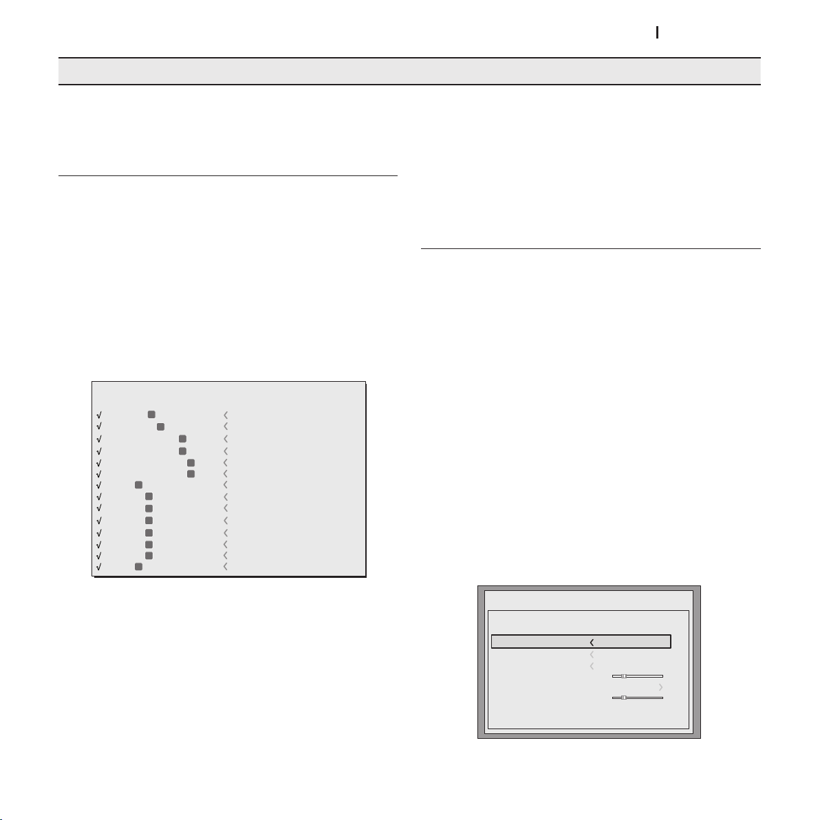
INPUTS
The input selection menu is opened by pressing 0 on the remote control or with the source key on the keypad. To select
an input, scroll through the list with the ▲ and ▼ keys until the
required input is highlighted, then press ▶.
Input selection menu display terminates if you press the
ESC
key or when the On-Screen Menu display timeout interval (set
in the Setup Menu) has elapsed or after the signal has been
recognised.
Some inputs can receive RGB and YPrPB signals. The input and
type of signal (RGB or YPrPb) are set in the pull down menu that
is displayed to the right of the symbol < when you press the
key ◀ (Fig. 17).
remote control corresponding to the selected source.
In the
SETUP
menu you can select whether or not to display this
information; for further information see
the
MENU
section.
SOURCE INFORMATION
MAIN MENU
Press the
MENU
key on the keypad or the
MENU+
or
on the remote control to access the main menu of the On
Screen Display.
The main menu is divided into four windows,
SETUP and MENU
, in which the various adjustments are grouped
PICTURE, IMAGE
according to the frequency of use. Use the ▲ and ▼ keys to
select the line corresponding to the adjustment you wish to
make (Fig. 18).
The various menus offer only adjustments corresponding to the
type of input signal displayed (e.g. certain typical adjustments
for video signals, not necessary for graphic signals, do not appear on the menus for the latter, and vice versa).
Some adjustments (
E.G. BRIGHTNESS
and
CONTRAST)
are associated
with a numerical value that can be modified within the set limits
using the ◀ and ▶ keys.
For others (e.g.
MODE
) you can choose between two options
offered on the same line and selectable using the ◀ and ▶
keys.
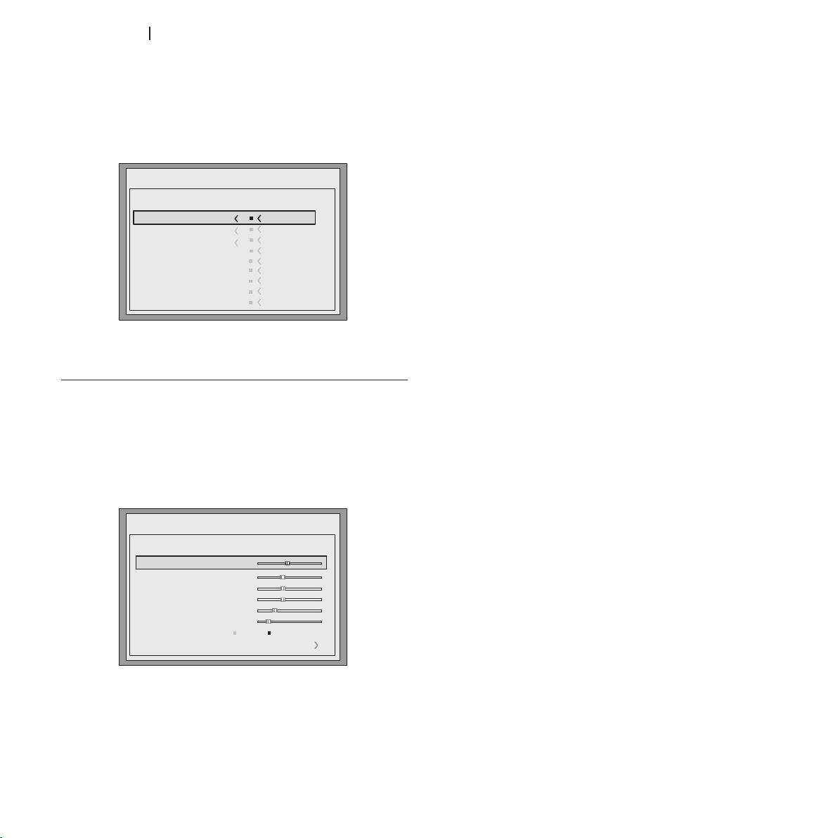
Other settings can be selected from submenus, which appear
as an superimposed window in which you make selections by
pressing the ▲ and ▼ keys (Fig. 19a/b).
MENU-
in
key
,
After selecting the signal that arrives from the source (using
the ▲ and ▼ keys), press
pull-down menu; to the right of the < symbol, you will see the
setting you have just entered.
During the short time that it takes to find the signal, a box will
appear showing the signal requested. Additional information regarding the signal such as the video standard (for video signals)
or definition (for graphic signals), the aspect and the current user
memory can be displayed by pressing the number key on the
MENU+/MENU-
to confirm and exit the
Fig.17
Fig. 19a
17
Page 18
ht5000HB - pro5dl
These sub-menus are accessed by pressing the key <. To exit
Menu
Pixel to pixel
Subtitles
Color temperature
gamma Correction
Position
Overscan
Y/C Delay
Aspect
Image
Normal
Anamophic
Letterbox
Panoramic
User 1
User 2
User 3
Menu
Picture
Contrast
Color
Tint
Sharpness
Filter
Cinema Mode
50
50
50
3
2
Off Auto
Auto
Noise Reduction
Brightness
60
and return to the upper level, press the keys
MENU+/-
.
To stop viewing the menus, press ESC on the remote control
or keypad, or wait for them to disappear automatically after
the number of seconds set in the
SETUP
page.
Fig.19b
For correct adjustment it may prove useful to display a grey
scale with at least twenty bands.
Now try to reduce the brightness of the black band as much
as possible while ensuring that it can still be distinguished from
the adjacent band with brightness slightly higher than black.
Alternatively use a scene composed of black objects alongside
other dark coloured objects and try to ensure that all the objects
can be separately identified.
CONTRAST
Use this control to adjust the images white level without affecting its dark areas. For correct adjustment it may prove useful
to display a grey scale with at least twenty bands.
Now try to increase the brightness of the white band as much
as possible while ensuring that it can still be distinguished from
the adjacent band with brightness slightly less than white.
Alternatively use a scene composed of well-lit white objects
surrounded by light objects with lower level lighting, and try to
ensure that all the objects can be separately identified.
PICTURE
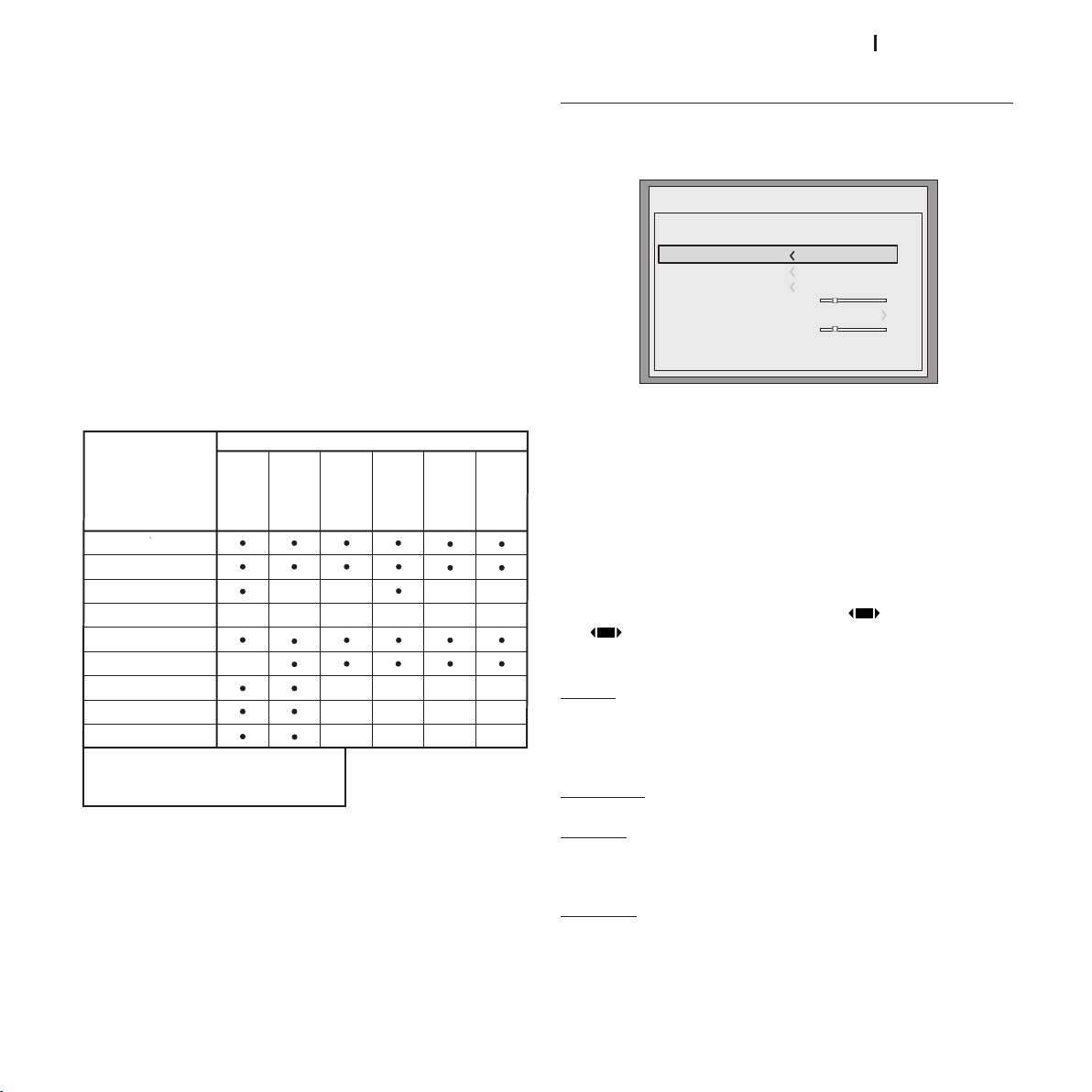
The setup menu groups adjustments that have an impact on
the image characteristics. Any adjustments not available for a
given input will not be displayed in the menu. Table 4 summarises the adjustments available for each input. For a complete
list of the on screen menus, refer to the paragraph
ON SCREEN MENUS
BRIGHTNESS
Use this control to adjust the darker areas of the picture (black
level), without affecting bright areas. Increasing the value will
give more detail in darker parts of the picture.
18
in the chapter
STRUCTURE OF
ADDITIONAL INFORMATION.
Fig.20
COLOUR
This control (also called Saturation) increases or decreases the
picture colour intensity. When set to zero, colour images will be
shown in black and white.
Increase the value until the colours appear natural: suitable
references include skin tones and the blue in grass in landscape shots.
TINT
This adjustment controls the purity of colours. Basically it determines the red-green ratio of the picture.
Decreasing the value increases the red content of the image,
increasing it increases the green content. For this adjustment
use skin tones or a test card image with colour bars as a reference.
SHARPNESS
This adjustment serves to modulate the signal to increase or
decrease the level of picture detail.
When the sharpness value is reduced the image details appear less pronounced, while increasing the value raises image
definition, making the outline of objects sharper.
Note that an excessively high value may result in a noisy picture and the edges of objects may appear unnaturally clearly
defined.
SHARPNESS MODE
This allows you to select the type of processing associated with
sharpness adjustment. For an interlaced or progressive video
Page 19
ht5000HB - pro5dl
signal, set to
Brightness
Contrast
Video
S-Video
RGBS
YPrPb
RGB Grafico
SDI
HDMI™
DVI
RGBS 15kHz
YPrPb 15kHz
Adjustment
Sources
Color - -
-
-
-
-
-
-
--
-
--
Tint
Sharpness
Sharpness Mode
Filter
Cinema Mode
Noise Reductions
-
-
-
(1)
(3) (3) (3)
(2)
(3)
(2)
(1) Present only if STANDBY VIDEO is NTSC
(2) Present only for interlaced video signals
(3) Presento only if SHARPNESS MODE is set on VIDEO
(4) Not avaible when DVI singol type is RGB
Menu
Color Temperature
Gamma Correction
Position
Y/C Delay
1
Overscan
1
Aspect
Image
If the
VIDEO
VIDEO
; for PC graphics signals, set to
option is set, it applies
Noise Reduction
GRAPHICS
.
to increase the
clarity of the image.
FILTER
This allows you to select the mode in which the input signal is
processed. Selecting the most appropriate value for a given
input signal ensures the best horizontal and vertical definition
and makes the picture sharper.
CINEMA MODE
Use this option if the video signal source is a movie film (obtained from a Telecin device with 3:2 or 2:2 pull-down). In this
case a de-interlace algorithm optimised for this type of signal
is applied.
Selecting AUTO mode causes the de-interlacer to analyse signal characteristics and apply the correct de-interlace mode
automatically.
IMAGE
This menu features adjustments relating to picture position,
aspect ratio, magnification etc. (Fig. 21).
Fig.21
ASPECT
This adjustment allows you to change the dimensions and
aspect ratio (relationship between width and height) of the
displayed image. There are six default aspects available and
three user aspects (with user-settable parameters). You can
select a different aspect for each source: the selected aspect
ratio will be automatically applied the next time the relative
source is displayed.
You can also select the required aspect ratio from the remote
control by repeatedly pressing the key or by pressing the
key and one of the number keys (1...8).
The following aspects are available:
If you select NO, the de-interlacer always applies an optimized
motion compensated algorithm for signals from a camera.
Present on all interlaced models.
NOISE REDUCTION
This adjustment lets you choose the value of the noise reduction filter.
This adjustment is available for all interlaced signals, but for
progressive inputs it is available only if
VIDEO
.
SHARPNESS MODE
is set to
NORMAL:
projects the image occupying the full height of the
screen while maintaining the aspect ratio of the input signal.
When the input signal aspect ratio is 4:3, black vertical bands
are displayed on the right and left of the picture.
ANAMORPHIC:
LETTERBOX:
correctly displays a 16:9 image.
displays a 4:3 letterbox image (source signal with black
bands above and below the picture) in such a way that it fills
the 16:9 screen and maintains the correct aspect.
PANORAMIC:
widens the 4:3 image cutting off a strip from the top
and bottom. Panoramic is ideal for displaying a 4:3 image on
the 16:9 screen of the Display.
19
Page 20
ht5000HB - pro5dl
SUBTITLES:
Native
HDTV
EBU
SMPTE-C
AUTO
User 1
User 2
Standard
High
T= 7500 K
White: x = 0,296
y = 0,325
Red: x = 0,653
y = 0,293
Green: x = 0,323
y = 0,653
Blue: x = 0,113
y = 0,033
= 0.009
Medium
Low
Native
D75
D65
D50
C
User
Image
1
R G B
2
White
3
Color Information
uv
Native
HDTV
EBU
SMPTE-C
AUTO
User 1
User 2
Standard
High
x = 0,113
y = 0,033
T = 5500K
Medium
Low
Native
D75
D65
D50
C
User
= 0.009
uv
x
y
Image
1
R G B
2
Bianco
3
Color Information
= 0.009
uv
this moves the image upwards, making room for the
subtitles to be seen.
PIXEL TO PIXEL
: makes a pixel to pixel map of any image, without
introducing any alteration to adapt it to the screen. The image is
projected in the centre of the screen and if its horizontal and/or
vertical dimensions are smaller than the display, it is bordered
by vertical and/or horizontal black bands.
PERSONAL 1, 2, 3
: can be used if none of the preset formats are
satisfactory. User formulas make it possible to continuously
adjust the picture size horizontally and vertically and hence
the aspect ratio.
The
PULL DOWN
menu, available for each aspect, permits you
to enable/disable the outlet to control the motorised curtains
used to block off the sides of 16:9 format projection screens
or the top and bottom of 4:3 format screens.
Fig. 22
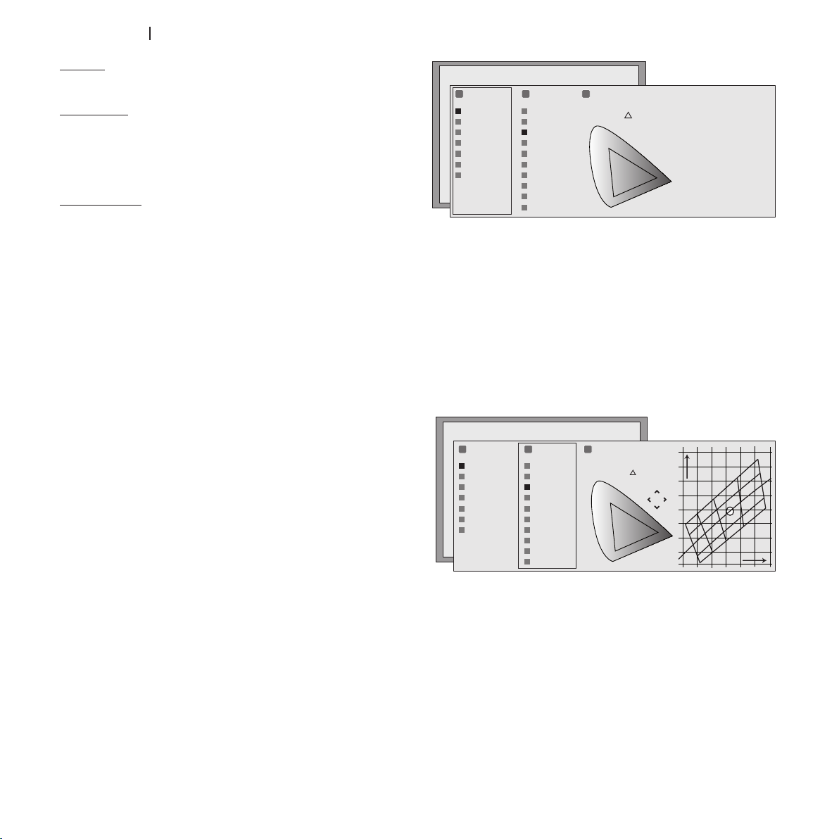
For use of settings in the column "1 RGB", there are 9 available
preset settings of the white balance.
The default settings are:
STANDARD applies a certain white balance depending on the
standard selected in column “1 RGB” (Fig. 23)
HIGH - MEDIUM - LOW (default white balance levels);
NATIVE (the machines native white balance);
D75 - D65 - D50 - C standard CIE illuminants;
COLOUR TEMPERATURE
Changes the colour balance of the image.
It is possible to define the position of the primary colours (red,
green and blue) using 5 preset settings (Fig.22).
The default settings are:
NATIVE (the projector’s native primary colours)
HDTV, EBU, SMPTE-C, primary colours defined by the standards
AUTO, mode that applies one of the standard settings described
above.
PC, mode available only if the projector has received Colour
Temperature instructions by connection to a PC and using Live
Colours Calibration software.
20
Fig. 23
If the default white settings are not sufficient, you can adjust the
white balance manually.
Colour temperature can be adjusted by positioning the white
point within the CIE chromaticity diagram. The system permits
you to place the white point inside a grid positioned in the neutral colour zone. Moving along the horizontal lines changes the
related colour temperature, with low temperatures on the right
(thus increasing the red content) and high temperatures on the
left of the graph (thus increasing the blue content). Points along
the yellow horizontal line represent the white balances on the
black body curve. The colour temperature along the vertical lines
Page 21
ht5000HB - pro5dl
is constant even if it differs to a lesser or higher degree from the
black body curve. This means that by selecting the points on the
higher part of the graph you will increase the green component.
On the contrary, by selecting points in the lower part of the graph,
the purple component increases.
GAMMA CORRECTION
Determines the systems response to the grey scale, emphasising
or attenuating the different grades of brightness (blacks, dark,
medium and light greys, whites) in the projected image.
The projector has a range of gamma functions which enable
you to display any image to the best effect for the type of
video source, the ambient lighting and your subjective preferences.
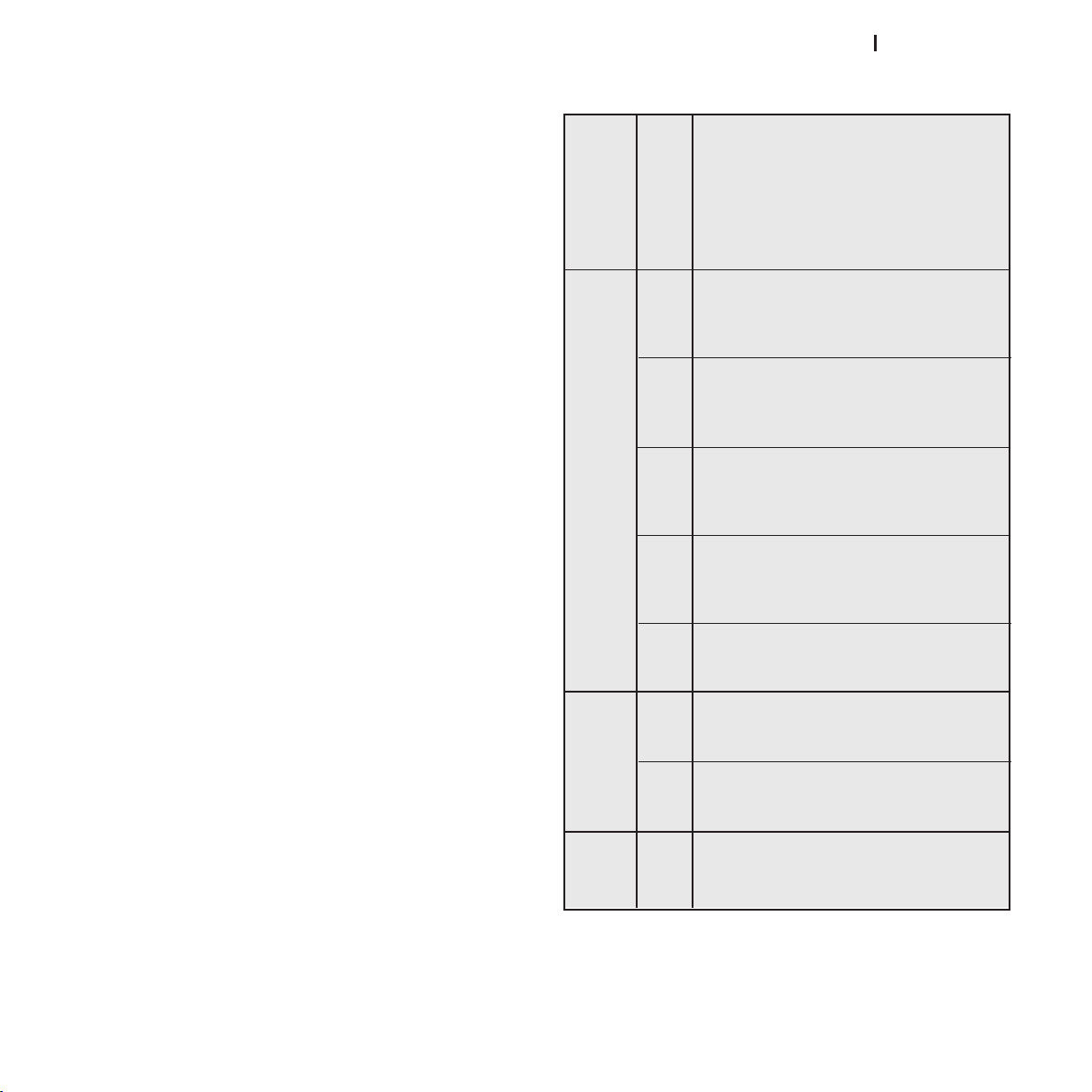
There are 3 sets of gamma curves: Standard (ST), Enhanced
SIM2 (EN) and Graphics (GR). The Standard curve has been
defined for general use, and is set for camcorders, digital
cameras, and for viewing films or photos from your PC. The
Enhanced set is suitable for watching movies. The Graphics
set is suited to displaying synthetic graphics (PC, CAD, PC
presentations, etc.).
By choosing User you can define your own curve. You can thus
select the coefficient which determines the curve. Coefficient
values from 1.5 to 2.2 allow you to emphasise the detail of dark
images, while reducing overall contrast. Values higher than 2.2
increase overall contrast, but reduce the detail of dark areas.
For the most common video sources, if you set the parameter
to 2.2, you will obtain pleasant and well-contrasted images.
OVERSCAN
Eliminates irregularities around the outer borders of the image.
Some less accurate sources may produce an image with
uneven borders; thanks to the overscan function these
imperfections can be moved outside the projected area.
POSITION
Use this adjustment to position the image vertically and horizontally. These parameters do not normally require adjustment
because the system checks the input signal and automatically
sets the most suitable values. However, if the image is not perfectly centred it may prove useful to make the system repeat
the input signal analysis and image positioning, requesting
the automatic control procedure with button A on the remote
control.
When this procedure is requested it is helpful to have a white
or light coloured background in the current picture on the
screen.
Table 5 - setting correct range
ST1 For general use.
Standard
Range Functions
EN1 Suitable for displaying images from
camcorders, digital cameras or TV studios
in bright ambient light.
EN2 Suitable for displaying images from
Enhanced SIM2
Range Functions
EN3 Suitable for projecting films in bright am-
EN4 Suitable for projecting films in moderate
EN5 Suitable for projecting films in controlled
GR1 Suitable for displaying graphic images
Graphics
Functions
G2 Suitable for displaying graphic images in
Gamma
USER Possibility of defining the curve by entering
User
camcorders, digital cameras or TV studios
in poor ambient light.
bient light.
ambient light.
ambient lighting conditions.
(e.g. Windows Desktop) in moderate
lighting conditions.
controlled lighting conditions.
parameters. The curve is defined by the
user.
21
Page 22
ht5000HB - pro5dl
Y/C DELAY
Video
S-Video
RGBS
YPrPb
RGB Grafico
RGBS 15kHz
YPrPb 15kHz
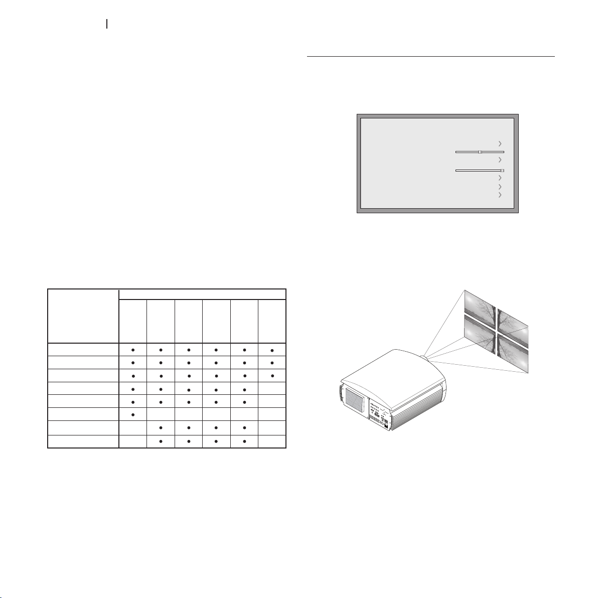
Adjustement
Sources
Y/C Delay
-
--
-
-
Position
-
-
Phase
-
Frequency
-
-
Color Temperature
Gamma Correction
Overscan
-
Aspect
HDMI™
SDI
DVI
Setup
Keystone
Lens
Lamp Power
Lamp Manangement
Test Pattern
Initial Settings
+0
300
Orientation
Where Video and S-Video signals are concerned, it may be
necessary to correct horizontal colour misalignment within the
projected image. For a given video standard (e.g. PAL or NTSC)
the stored value does not normally require further adjustment,
unless the source or connection cable is changed.
FREQUENCY/PHASE
These adjustments, available for progressive signals and for signals from a PC, ensure correspondence between the number
of pixels making up the signal and the number of pixels that
make up the projected image.
It is not normally necessary to adjust these parameters because
the system checks the input signal and automatically sets the
most suitable values. If however the image is disturbed (loss of
resolution between equidistant vertical bands or instability and
lack of detail in thin vertical lines) it may help to ask the system
to rerun the input signal analysis and set the best parameters by
requesting the automatic adjustment function with button A on
the remote control or
AUTO
on the keypad. If the automatic procedure fails to achieve the required effect, enter the frequency
and phase values manually and move sufficiently close to the
screen to observe the effects of the adjustments.
SETUP
This menu includes the less frequently used adjustments which
may be helpful during installation (for example, the selection
of the language for the On Screen Display or the display of test
images) (Fig.25).
Fig.25
ORIENTATION
Reverses the image vertically and horizontally to best fit the
installation: i.e. desktop front, ceiling front, desktop rear and
ceiling rear.
22
Fig.26
HORIZONTAL/VERTICAL KEYSTONE
To achieve the best image quality, we recommend installing the projector on a surface which is perpendicular to the
screen. If the image slopes left or right, adjust the feet on the
bottom of the projector to obtain a level position, lining up the
base of the projected image with the base of the projection
screen (Fig. 27).
Page 23
ht5000HB - pro5dl
Fig.27
No
Confirm?
Yes
KEY STON E
20%
If this adjustment is insufficient to centre the image on the
screen, tilt the projector and use the Vertical/horizontal keystone
adjustment to compensate for the resulting distortion.
LENS
The ZOOM adjustment controls the motorised lens zoom,
permitting you to zoom in or out, enlarging or shrinking the
projected image.
This permits you to access the optic zoom control, where the
◀ and ▶ keys zoom in and out.
FOCUS adjustment changes the motorised lens focus.
It provides the maximum definition of the projected image.
Exact focusing should make it possible, from near the screen,
to distinguish every single pixel that makes up the image. With
the initial settings of the projector, the configurable keys of the
remote control (F1, F2) perform the functions of optical zoom
and optical focus (Fig.30).
POWER ON
If active
(AUTO)
, this option permits the system to be switched
on whenever the projector is connected to the mains power
supply.
In STANDBY mode the projector remains in STANDBY mode
and awaits the power-up command from the remote control
or keypad.
Fig.28
INITIAL SETTINGS
Resets the projector to its initial factory settings (except Position,
Orientation, Y/C Delay, Zoom and Focus). Before performing
this operation, confirmation is requested (Fig.29).
Fig.29
LAMP POWER
If your projection room is especially dark, the images projected by the HT5000HB - PRO5DL system may appear to be
excessively bright. Use the LAMP POWER function to reduce the
power used to operate the lamp while achieving maximum
image quality. In this way, the brightness of the image will be
adapted to your projection conditions guaranteeing that the
lamp lasts longer.
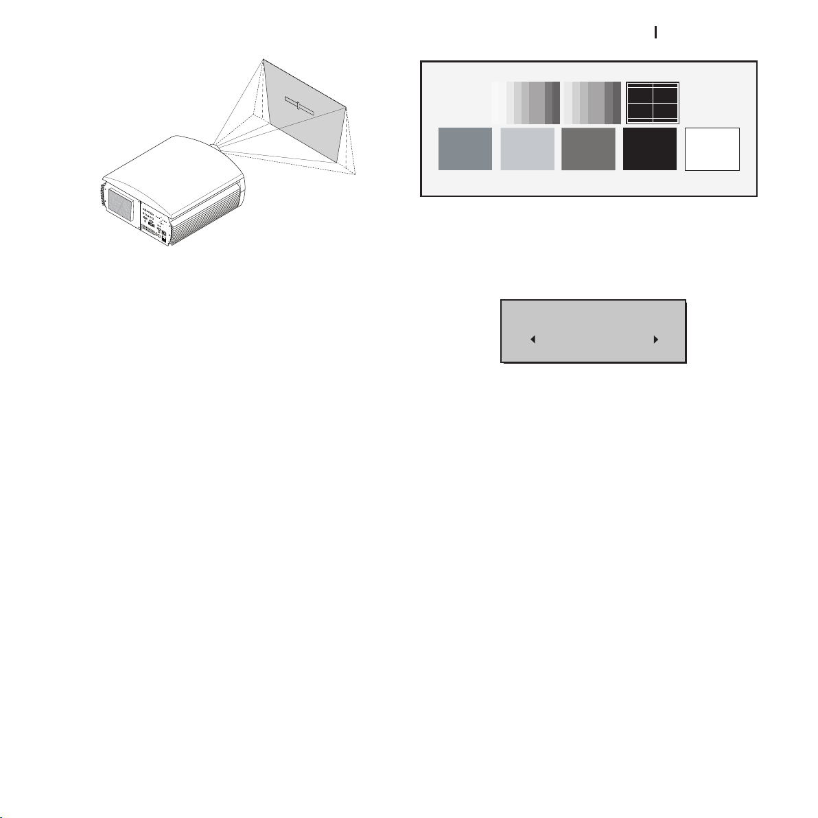
TEST PATTERNS
Displays a series of five test patterns, which are useful when
installing the system and checking basic functions. Use the ◀
and ▶ keys to select the various test patterns (Fig. 28).
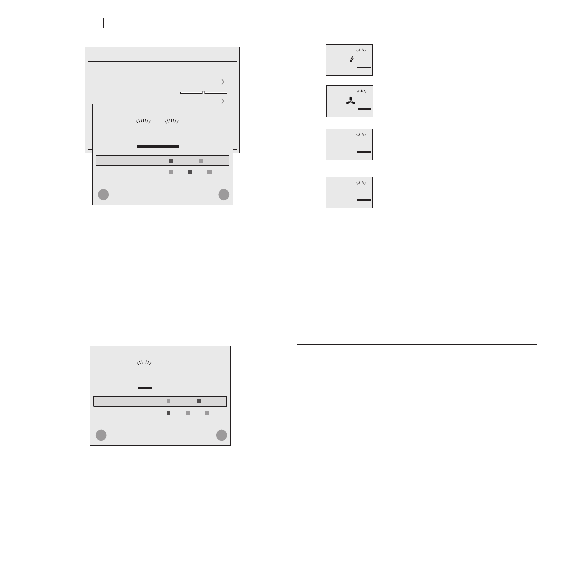
MANAGEMENT OF LAMPS
The projector has two lamps with the following operating modes
(Fig. 30):
Double,• with both lamps in operation, for maximum
brightness from the projector
Single, • with only one lamp on, for longer-lasting lamps.
23
Page 24
ht5000HB - pro5dl
Lamp Power
Lamp Manangement
Test Pattern
Initial Settings
300
1 2
Lamp Mode SingleDouble
Cancel Confirm
Lamp Selection 21 Alt
+
-
Lamp Management
Menu
Setup
Keystone
Lens
Lamp Power
Lamp Manangement
Test Pattern
Initial Settings
+0
300
Orientation
1 2
Lamp Mode SingleDouble
Cancel Confirm
Lamp Selection 21 Alt
+
-
Lamp Management
Fig.30
Lamp Power
Lamp Manangement
1
x
Lamp Power
Lamp Manangement
1
Lamp Power
Lamp Manangement
1
Lamp Power
Lamp Manangement
1
!
Lamps being lit
(this symbol appears when a lamp is
being lit)
Lamps in cooling phase
(this symbol appears when a lamp is
cooling off)
Malfunction
A malfunction in indicated in the graphic
description by the symbol '!'.
Lamp not working
(this symbol appears after a series of
attempted uses are unsuccessful).
Any variation takes place only after pressing the confirmation
key (+). The confirmation may take effect:
immediately• , for transition for 'Double' to 'Single' mode
or vice versa
delayed• (at next start-up from standby), for transition in the
ambit of Single mode.
IN THE GRAPHIC REPRESENTATION:
24
a selected lamp is shown by having the corresponding •
number underlined
a lamp that is in operation is shown with a symbol above •
the corresponding number
a lamp being turned on or cooling off is shown by symbols •
alongside the corresponding number.
If a lamp fails to light, the projector will attempt to provide
projection in the best conditions possible:
if in "Double" mode, by turning on the lamp that is still •
working
if in "Single" mode, by turning on the other lamp, i.e. the •
one that is not selected.
MENU
LANGUAGE
Makes it possible to select one of the languages available for
the On Screen Display menus.
SOURCE LIST
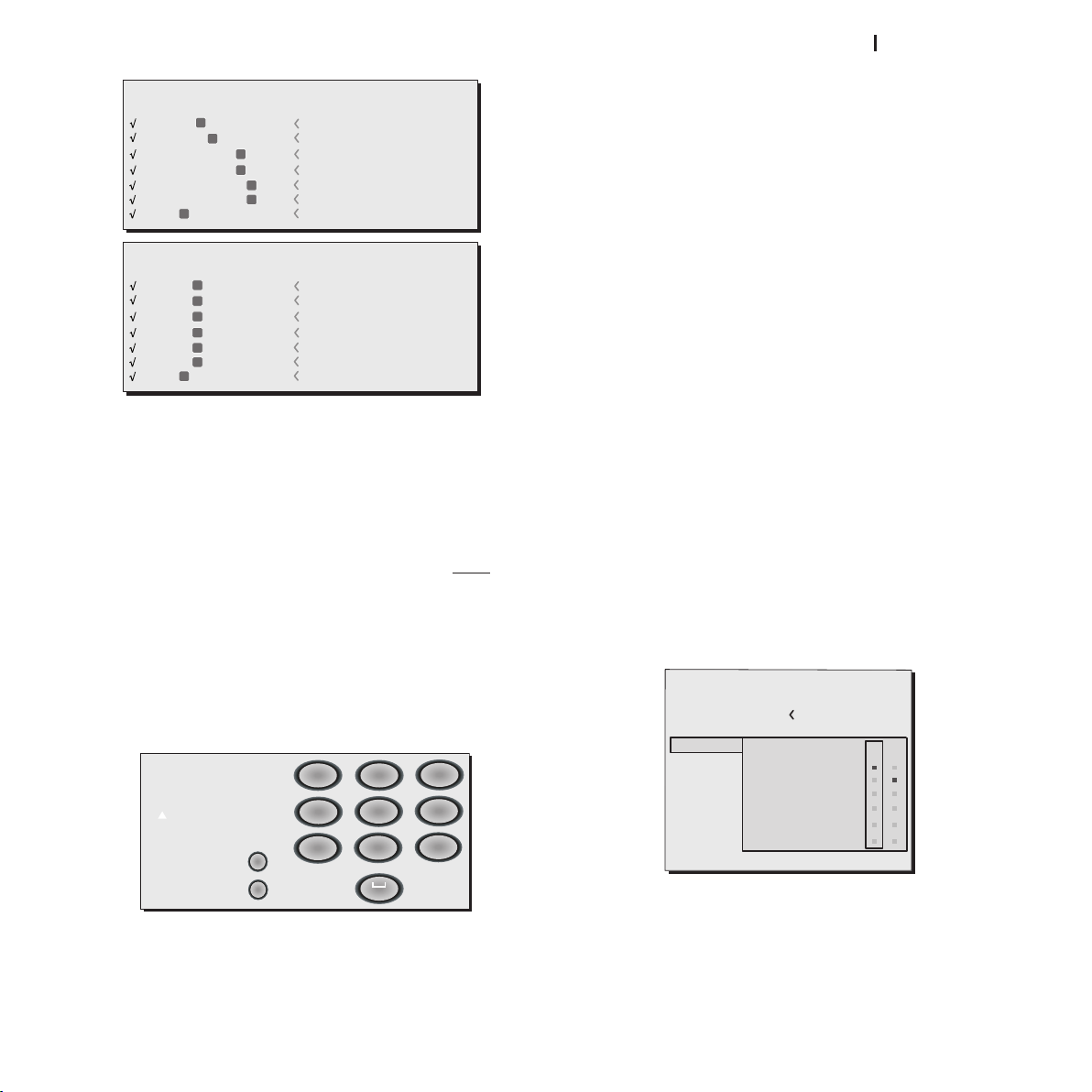
In order to make the HT5000HB - PRO5DL system increasingly flexible, the functions described below make it possible
to modify the input selection menu and adapt it so that it
Fig.31
matches the requirements of the user more closely. The main
page displays all the source inputs physically connected to
the projector.
You can delete any inputs which are not in use. To do this,
select the input in the pull down menu which appears when
you press ◀, and choose whether to enable or disable the
input (Fig. 32).
Enabling or disabling of sources will automatically cause the
renumbering of the remaining active inputs.
Page 25
ht5000HB - pro5dl
2 S-VIDEO
5 GRAPHICS RGB
3 COMPONENT
1 VIDEO
1
2
3
5
S-VIDEO 3
GRAPHICS 1
COMPONENT 1
VIDEO 1
4 COMPONENT
4
COMPONENT 2
6 GRAPHICS RGB
6
GRAPHICS 2
7 DVI
7
DVI
Source List / Rename Source 1/1
9 HDMI
12 HDMI
10 HDMI
8 HDMI
8
9
10
12
HDMI 2
HDMI 5
HDMI 3
HDMI 1
11 HDMI
11
HDMI 4
13 HDMI
13
HDMI 6
14 SDI
14
SDI
Source List / Rename Source 2/2
Cancel
Confirm
Rename Source
()?@
1
ABC
2
DEF
3
GHI
4
JKL
5
MNO
6
PQRS
7
-
+
TUV
8
0
WXYZ
9
_ _ _ _ _ _ _ _ _ _ _
Fig.32
Source List
F1/F2 Keys
Source Info
OSD Backgro
OSD Position
OSD Timeout
Linguage
Menu
English
Zoom
Focus
Magnification
Blank
Gamma Correction
Color temperature
F1
Active video signal sources (shown in the input selection menu)
are ticked.
It may be useful to identify the input with a user defined name
rather than the type of signal (for example, with the name of
the connected device).
When you have decided to display an input, select
NAME
in the
pull-down menu and rename the source currently in use.
This makes it easier to remember which source is connected to
a given input; you can use up to 12 alphanumeric characters
for the name (for further details, see
ENTERING TEXT
).
Text input mode is the same whether you are editing an existing name or entering a name for the first time. Characters can
be entered in any of the available positions (represented by
horizontal lines). Use the ◀ and ▶ keys to move the cursor left
or right respectively.
Press the number key corresponding to the character; pressing
once selects the first character, twice, the second character
and so forth. The available characters are shown in the text entry
menu that appears in this setup mode. Once you have entered
a character, move to the next space on the right to enter the
next with the ▶ key on the remote control, and repeat the
procedure. This applies even if the letter is associated with the
same key as before. Use the ▲ key to switch from upper case
to lower case characters and vice versa. Cancel errors with ▼
after selecting the character to be cancelled. Once you have
completed the text entry procedure confirm your text and save
it by pressing the
cancel the changes, press
MENU+
key on the remote control.If you wish to
MENU-
on the remote control.
F1-F2 KEYS
The remote control is equipped with two keys (F1 and F2) which
are associated with various different functions.
The screen shows six options, one for each line, and two columns indicating the keys F1-F2. You can select F1 and F2 with
the ◀ and ▶ keys on the remote control; select the function to
assign to F1 or F2 with the ▼ and ▲ keys
The function performed by the key is indicated by the dot at
the line-column intersection (Fig.34).
The six menu items are described below.
Entering text
The text entry menu shown in Fig. 33 makes it possible to enter
text quickly and easily.
Fig.33
Fig.34
Focus
Once selected, the keys ◀ and ▶ allow the image to be
focused.
25
Page 26
ht5000HB - pro5dl
Enlargement
0 Auto
3 S MEMORIA 1
4 S MEMORY 4
5 S MEMORY 5
6 S MEMORY 6
Memories
Save current setting
Save initial setting
Rename
2 I
1 S
Activates the electronic zoom, the keys ◀ and ▶ zoom in on
the image. If you press the key again you will enter
PAN
mode
in which the ◀ and ▶, ▼ and ▲ keys enable you to pan over
the enlarged image. When the ▼ key is pressed a third time,
the system resets the projector to original viewing settings.
Blank
Switches off the video signal and displays a blank screen.
As soon as the key is pressed an OSD message lasting a few
seconds confirms that the function has been activated. You
can restore the previous conditions by pressing any key on the
remote control.
Gamma correction
Successive pressing of the key in question (F1 or F2) makes it
possible to select any of the available gamma curves.
SOURCE INFORMATION
When enabled
tion regarding the signal type is displayed. If disabled,
(YES)
each time the source is changed informa-
(NO)
no
information on the source is displayed.
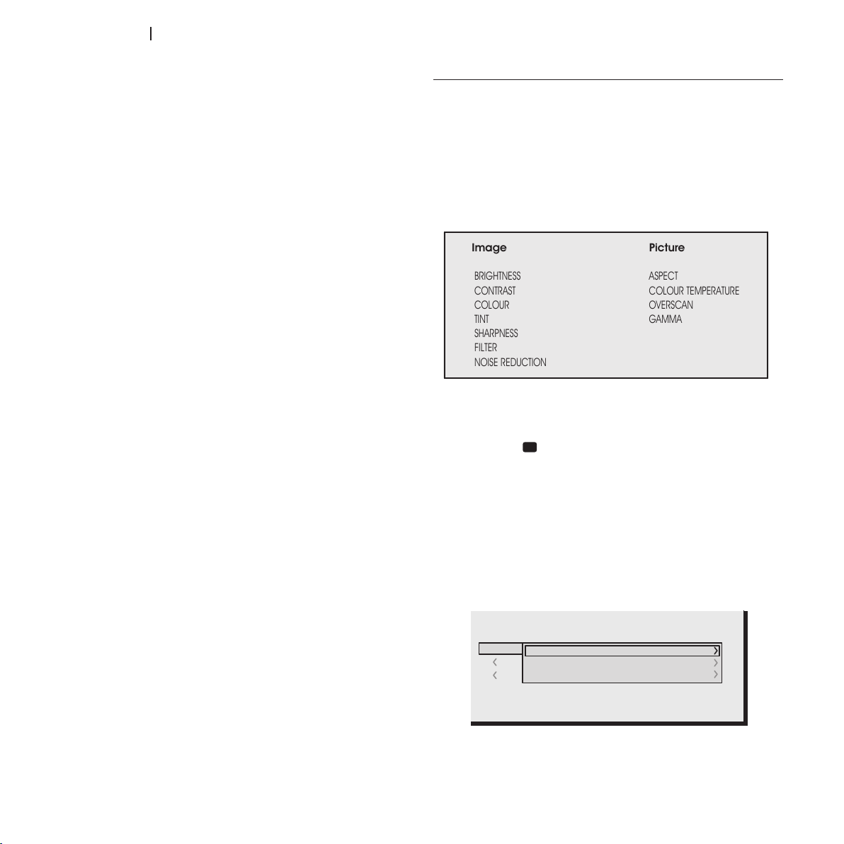
MEMORIES
The main picture parameters can be saved in discrete sets of
values called
plied as a group using a single command.
There are 6 separate Memories (Memory 1, Memory 2.... -6)
for each of the 14 signal types handled.
The following image parameters can be saved/recalled by the
Memory Management system:
Image Picture
BRIGHTNESS ASPECT
CONTRAST COLOUR TEMPERATURE
COLOUR OVERSCAN
TINT GAMMA
SHARPNESS
FILTER
NOISE REDUCTION
MEMORIES
so that they can be subsequently ap-
OSD BACKGROUND
Determines the type of background for the On Screen Display
opaque or transparent.
OSD DISPLAY TIMEOUT
Determines the On Screen Display timeout after the last event
(adjustment using remote control or keypad).
The adjustment is made using the ◀ (decrease) and ▶ (increase) keys within a 6-200 second timeframe.
OSD POSITION
Positions the On Screen Display in a particular area of the
projected image. The OSD can be positioned using the arrow
keys for fine adjustments or keys 1...9 on the remote control to
select one of 9 default positions.
26
Some of these parameters may not be available for certain
inputs or certain input signals, as indicated in Tables 4 and 5.
The Memory Management function menu page is activated
by pressing the key on the remote control.
Saving a memory
To save the current image settings in Memory 1, move the cursor to line 1 using the ▼ and ▲ keys and open the drop-down
menu by pressing the ◀ key (fig. 35). Select the “Save initial
settings” line. The message, “Initial settings saving in Memory
1” will be shown at the bottom of the display to confirm that
the operation has been completed. Repeat the operation to
save other image settings in new memories.
Fig.35
Page 27

ht5000HB - pro5dl
Using a memory
To use a Memory, select the line in question and press the
▶ key. The settings stored in the memory you have selected
will be applied to the projected image, while a message will
confirm that Memory has been applied. The memory will be
associated with the particular source and signal type and will
be automatically applied whenever that particular combination of source and signal type is selected.
Restoring initial settings for a memory
When you need to restore the initial settings in a Memory that
has previously been modified, select the line referring to the
Memory in question and open the corresponding pull-down
menu (key ◀). Then select the “Save initial settings” line.
A message stating “Initial settings saved in Memory 1” will appear at the bottom of the display.
Renaming a memory
All Memories can be named. To assign a name (with a maximum length of 12 alphanumeric characters) to a Memory,
select the Rename option from the corresponding pull-down
menu. Enter the text as described in the paragraph
Restoring current settings
When you enter the
tings is saved in a temporary memory (
one or more memories have been recalled, you can restore
the settings that were effective at the moment the Memories
menu was accessed by selecting
this operation must be performed before the
page disappears (30 seconds after the last operation with the
remote control or keypad). The next time it appears, in fact,
the temporary memory will contain new information that takes
account of any Memories selected on the last time but one
that the
Memory 0 can be used even when you do not wish to enable
Memories management for the signal in use. In fact, once
Memory 0 has been selected, when a source is chosen, the
settings that were effective at the time the Memory was previously recalled will be automatically applied.
MEMORIES
MEMORIES
page was accessed.
menu a copy of the current set-
Memory
marked 0 - AUTO
0 (
0 - AUTO).
TEXT ENTRY
). Once
Note that
MEMORIES
menu
INFO
Displays the current operating status of the projector and information concerning the projected video/graphic signal.
This function is displayed by pressing the key on the remote
control (or, when the On Screen Display is not enabled, the ▶
key on the keypad).
QUICK MENUS
The quick menus provide access to the main adjustments that
affect image quality without opening the main menu.
NESS, CONTRAST, COLOUR, TINT, SHARPNESS, FILTER
adjustments appear at the bottom of the screen one after
the other when the ▼ and ▲ keys are pressed.
MESSAGES
The following messages may appear on your screen:
No signal
.
The system does not recognise any signal applied to the selected input. In this case:
• Make sure the selected input is connected to a video or
graphic signal and that that source is functioning correctly.
• Check the condition of the cables used to connect the
system to the various sources.
• Make sure the video or graphic signals supplied by the
source are compatible with the system’s technical specifications and, in particular, with those of the selected input.
Out of range
This message appears when either the resolution or the vertical/horizontal frequency of the input signal exceeds system
specifications (e.g. a QXGA graphic signal).
and
NOISE REDUCTION
BRIGHT-
27
Page 28
ht5000HB - pro5dl
9 CLEANING AND MAINTENANCE
The projector does not require internal adjustment.
There are no user serviceable parts inside the projector.
To replace the bulb or any other repairs, contact your local
service centre, whose engineers will be happy to efficiently solve
any problem. Use a soft cloth to clean the projector housing, if
necessary slightly dampened with water and a small amount
of neutral soap. Do not rub the rear panel markings.
10 TROUBLESHOOTING GUIDE
No power (LEDs always off)
• Check that the projector’s power switches are in position
I.
• Check that the power cables are correctly connected to
the projector’s power sockets.
• Check the condition of the fuse located next to the power
socket at the rear of the projector.
• Replace the fuse located on the projector’s power socket
with an identical type (T 5A H).
• If the fuse blows repeatedly, seek technical assistance from
your nearest service centre.
Lamp fails to switch on
The lens may be cleaned with a small very soft, non-abrasive
brush, to remove dust particles. Alternatively, use a soft dry
cleaning cloth (of the type used for camera lens cleaning) to
remove fingerprints and grease marks.
We suggest cleaning the filter every time that the lamp is
changed.
No image
Make sure the selected input is connected to a video or graphic
signal and that this source is functioning correctly.
• Make sure the video or graphic signals supplied by the
source are compatible with the HT5000HB - PRO5DL
system’s technical specifications and, in particular, with
those of the selected input.
• Check the condition of the cables used to connect the
projector to its input sources.
• Check the state of the connection by interpreting the code
displayed by the projector LEDs.
• Make sure the cooling air vents on the units are not blocked
and that the room temperature is below 35°C.
• If this happens immediately after the last time the unit was
switched off, allow a few minutes between switching off
and switching on again. This will allow the lamp to cool
down to the optimum temperature for switching on.
• If the lamp fails to light - even though the unit has had time
to cool down - seek technical assistance from your nearest
service centre.
• Check the state of the connection by using Table 1 to
interpret the code displayed by the system LEDs.
28
Image is disturbed, unstable or noisy
• Check compatibility of the video or graphic signals with the
technical specifications of the projector, and specifically,
with the specifications of the selected input.
• Check all cables.
• If the problem occurs on a terrestrial broadcast source
signal, check that the receiver has been correctly tuned
in and that the aerial system is in good working order.
• If the problem occurs in a video signal from a video re-
corder, ensure that the videotape is in good condition and
that
VCR
mode is active in the
• Adjust the Sharpness parameter in the
optimise the projected image.
PICTURE
menu.
PICTURE
menu to
Page 29

ht5000HB - pro5dl
Incomplete image around the edges (vertical or horizontal)
Graphic image with poor quality vertical detail
• Check compatibility of the video or graphic signals with the
technical specifications of the system, and in particular,
with the specifications of the selected input.
• Open the automatic image adjustment function by press-
ing the key A on the remote control or ◀ on the projector’s
keypad.
• Adjust the horizontal or vertical position of the image with
the
IMAGE/POSITION
tion).
• Adjust the image width and height, selecting Aspect in the
IMAGE /ASPECT
• Adjust the overscan setting applied to the image on the
IMAGE/OVERSCAN
Image too dark/pale or unnaturally coloured
• Check compatibility of the video or graphic signals with the
technical specifications of the projector, and in particular,
with the specifications of the selected input.
• Adjust the
in the
PICTURE
• If necessary, adjust
TION (IMAGE
menu (if available for the input in ques-
menu.
menu.
CONTRAST, BRIGHTNESS, COLOUR
menu.
COLOUR TEMPERATURE
menu).
and
and
TINT
parameters
GAMMA CORREC-
• Check compatibility of the video or graphic signals with the
technical specifications of the projector, and in particular,
with the specifications of the selected input.
• Press key A on the remote control or ◀ on the projector
keypad to execute automatic adjustments.
• Adjust the
to optimise the vertical details of the image (if available
for the input in question).
Video image with colours not aligned with vertical details
• Check compatibility of the video or graphic signals with the
technical specifications of the system, and in particular,
with the specifications of the selected input.
• Adjust
misalignment.
Remote control does not work
• Check remote control battery power and that they are
inserted correctly.
• Ensure the area between the infrared sensors (on the front
panel of the projector) and the remote control is free from
obstructions.
• Make sure the infrared sensors on the front and rear of the
projector are not exposed to very bright light levels.
FREQUENCY
Y/C DELAY
and
PHASE
settings in the
settings in the
IMAGE
menu to reduce colour
IMAGE
menu
11 OPTIONAL ACCESSORIES
You can purchase the following optional accessories at your
Dealer:
- CEILING MOUNTING KIT
- OPTIONAL LENSES
A range of lenses are available from our dealers to satisfy
varying installation and projection distance needs. See the
Additional Information chapter for further details on projection
distance and enlargement ratios.
Always contact our service centre to have the lens replaced.
Use only original or SIM2 Multimedia approved accessories.
WARNING: for ceiling/wall installation, using a suspension
bracket, carefully follow the instructions and safety regulations provided with the bracket in the packaging.
29
Page 30

ht5000HB - pro5dl
TECHNICAL SPECIFICATIONS
ELECTRONICS
Input signals:
• 1 COMPOSITE VIDEO (CVBS)
gilded RCA type connectors
1.0 Vpp / 75 Ω, negative synchronisation
• 1 S-VIDEO (Y/C)
4 pin mini-DIN connectors
Y: 1.0 Vpp / 75 Ω, negative synchronisation
C: 0.286 Vpp / 75 Ω, [NTSC burst rated level]
0.3 Vpp / 75 Ω [PAL, SECAM burst rated level]
• 2 COMPONENTS (Y/Pr/Pb/) - RGBS
1 set of 4 RCA connectors
1 set of 5 BNC connectors
- Component signal
Y: 1.0 Vpp / 75 Ω,
YPrPb:0.7 Vpp / 75 Ω
- RGB Signal
R,B: 0.7 V
G: 0.7 Vpp / 75 Ω, HV synchronisation
1.0 Vpp / 75 Ω,
Positive or negative TTL, 5 Vpp / 1 kΩ
• 2 RGBHV (RGB analogue)
female DB15HD-type connectors
R,B:0.7 Vpp / 75 Ω
G:0.7 Vpp / 75 Ω, separate H, V or HV synchronisation
1.0 Vpp / 75 Ω,
Positive or negative TTL, 5 Vpp / 1 kΩ
• 1 DVI (RGB-YPrPb digital) connector DVI-D female
• 6 HDMI HDCP
• 1 HD-SDI (connector BNC)
Control: Keypad on rear input panel, remote control, via
Horizontal frequency: from 15 to 80 kHz (up to UXGA format @ 65 Hz)
Vertical frequency: 48 -100 Hz, 24Hz @ 1080p
Video standard: automatic selection (PAL B,G,H,I,M,N,60, SECAM,
Graphic standards: VGA, SVGA, XGA, SXGA, UXGA
High definition standard: ATSC HDTV (480p, 720p, 1080i, 1080p)
Colour temperature: from 5500K to 9000K
Contrast: >5000:1
Lamps: 2 of 300W (can be dimmed to 250W)
Outputs: 2 12V jack connectors (1 active when system
pp
negative or 3 level synchronisation [HDTV]
/ 75 Ω
negative or 3 level synchronisation [HDTV]
negative or 3 level synchronisation
RS232 from PC or home automation devices,
USB 1.1, LAN RJ45
NTSC 3.58 and 4.43)
powered, 1 active when 16:9 aspect ratio
selected)
[HDTV]
GENERAL PROJECTOR
Power cable: (EU, UK and US); 2m long
Power supply: from 110 to 240 V AC, tolerance +/- 10%
frequency from 48 to 62 Hz
Power absorbed: 850 W max
Fuse: T 10 A H, 5 x 20 mm
Dimensions: 570 x 277 x 720 mm (WxHxD)
Weight (approx): ~45 kg
Operating temperature: 10 to 35°C
Shipping temperature: -15 to 55°C
Storage temperature: -15 to 55°C
Humidity: 20% to 95% without condensation
Safety: EN 60950
UL60950
Portability: considered “desktop equipment”
Electromagnetic compatibility: EN 55022 Class B
EN 55024
EN 61000-3-2
EN 61000-3-3
Transport: IEC 68-2-31, IEC 68-2-32
30
Page 31
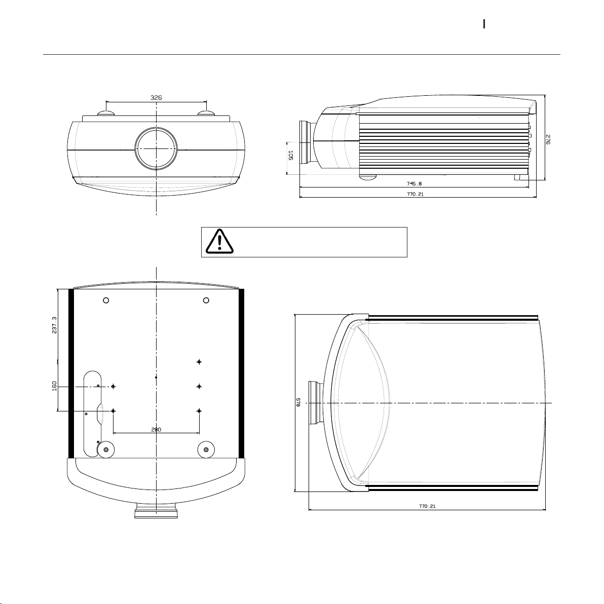
ht5000HB - pro5dl
DIMENSIONS
THE SPECIFIED LENGTH IS WITH STANDARD
(*)
LENSES INSTALLED
31
Page 32
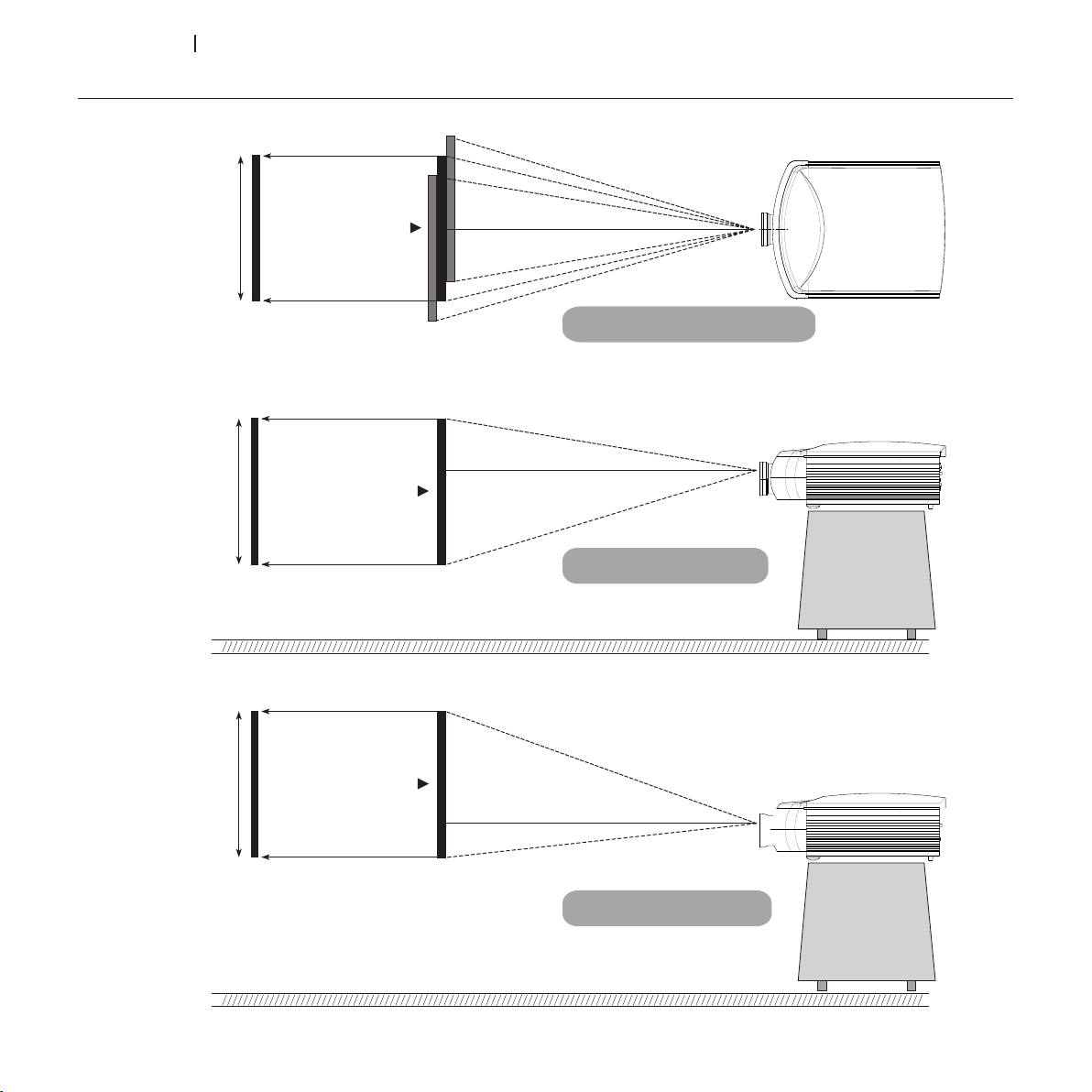
ht5000HB - pro5dl
HORIZONTAL AND VERTICAL SHIFT - TILT
Screen
height
- 30% Vertical Shift
+/- 15% Orizontal Shift
+70%
Vertical Shift
Screen Center= 0
Screen Center= 0
Screen Center= 0
Screen
width
Screen
height
32
Page 33
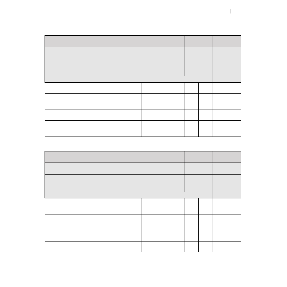
ht5000HB - pro5dl
PROJECTION DISTANCES
Meters
Feet
Lens Type FWA -1* FWA -2* Short Med-Short Med-Long Long
Ratio**
0.67:1 1.11:1 1.39~1.87:1 1.87~2.56:1 2.56~4.16:1 4.16~6.96:1
1.1 - 3.2 3 -15 4 - 24 4 - 24 9.1 - 45 12 - 80
Throw Distance
(meters)
Image Width Fixed Fixed Min Max Min Max Min Max Min Max
meters
1.5 1 2.1 2.8 2.8 3.8 3.8 6.2 6.2 10.4
3 2 3.4 4.2 5.6 5.6 7.7 7.7 12.5 12.5 20.9
4.5 3 5 6.3 8.4 8.4 11.5 11.5 18.7 18.7 31.3
6 6.7 8.3 11.2 11.2 15.4 15.4 25.0 25.0 41.8
9 10 12.5 16.8 16.8 23.0 23.0 37.4 37.4 62.6
10.5 12 14.6 19.6 19.6 24.0 26.9 43.7 43.7 73.1
13.5 15 18.8 24.0 25.2 34.6 34.6 45.0 56.2 80.0
Throw
Distance
Throw
*FWA – Fixed Wide Angle
** Throw Distance/Image Width
Lens Type FWA -1* FWA -2* Short Med-short Med-long Long
Throw
Ratio**
0.67:1 1.12:1 1.39~1.87:1 1.87~2.56:1 2.56~4.16:1 4.16~6.96:1
Throw Distance (feet)
Image Width Fixed Fixed Min Max Min Max Min Max Min Max
feet
5 3.3 5.6 7 9.4 9.4 12.8 12.8 20.8 20.8 34.8
10 6.7 11.2 13.9 18.7 18.7 25.6 25.6 41.6 41.6 69.6
15 10.0 16.8 20.9 28.1 28.1 38.4 38.4 62.4 62.4 104
20 13.4 22.4 27.8 37.4 37.4 51.2 51.2 83.2 83.2 139
30 20.1 33.6 41.7 56.1 56.1 76.8 76.8 125 125 209
35 23.4 39.2 48.7 65.5 65.5 89.6 89.6 146 146 244
45 30.1 50.4 62.6 84.2 84.2 115 115 187 187 262
(min - max)
3.2 - 9.9 9.9 -49 13.1-78.7 13.1-78.7 29.5 -147 39.3 - 262.3
Distance
Throw
(min - max)
(m)
(ft)
33
Page 34

ht5000HB - pro5dl
GUARANTEE
Guarantee clauses
1. The unit is guaranteed for a period of 24 months from the
date of purchase or installation as shown by a delivery document from the retailer or by another document that shows
the name of the retailer and the date of sale.
The guarantee is valid only in Italy.
2. The guarantee covers repair or replacement of the components that are acknowledged as originally defective due
to manufacturing defects.
3. The guarantee does not cover parts that are defective due
to transport, negligence or carelessness in use, incorrect
installation or maintenance by unauthorized personnel, use
of the unit which is improper or different from its intended
use, or any circumstances which are not attributable to
manufacturing defects in the unit. The guarantee does not
cover removable items or accessories unless it has been
proven that there is a manufacturing defect.
The guarantee also does not cover technical work concern-
ing the installation and/or testing of the unit, nor parts that
are subject to normal wear.
4. The guarantee is applicable provided installation allows
normal access to the unit.
For special installations (ceiling, wall, etc.) the user is re-
sponsible for bringing the unit back down to a serviceable
height.
5. The manufacturer shall not be held liable for any damage
which may be caused, directly or indirectly, to persons, pets
or property due to failure to comply with all of the provisions
of the instructions booklet, especially warning concerning
installation, use and maintenance of the unit. The manufacturer shall not be held liable for direct and/or indirect
damage caused by or resulting from use of the unit.
6. For units for which call-out service is requested and/or provided, the user is required to pay the fixed amount for call-out
travel expenses in effect at the time of the call-out. If the
unit is repaired at a technical service centre authorized by
the manufacturer, the user is liable for expenses and risks in
shipping.
7. 24 months from the date of purchase, the unit is no longer
covered by a guarantee and service will be provided with
charges for the replaced parts, for labour, and for transportation for personnel and materials in accordance with current
rates in the possession of the staff of technical service centres
authorized by the manufacturer. If work is to be performed
at one of the technical service centres authorized by the
manufacturer, the unit must be delivered with the user assuming liability for expenses and risks.
8. This is the only guarantee that is valid. No-one other than
the manufacturer is authorized to extend or modify its terms
or to issue any other, written or verbal. HOWEVER, under no
circumstances will the unit be replaced or the guarantee
extended in the event of a defect.
34
Page 35

SIM2 Multimedia S.p.a. Viale Lino Zanussi, 11 33170 Pordenone - ITALY
Phone +39,434,383,253-256 Fax +39.434.383260-261
www.sim2.com e-mail: [email protected]
SIM2 USA Inc. 10108 USA Today Way 33025 Miramar FL - USA
Phone +1.954.4422999 Fax +1.954.4422998
www.sim2usa.com e-mail: [email protected]
SIM2 Deutschland GmbH Arndtstrasse 34-36 - D-60325 Frankfurt Am Main
Phone 0800.800.7462 (Germany only)
Int. Phone: +49-163-500 7462
Fax 0800.900.7462
www.sim2.de - e-mail: [email protected]
Steinway House Worth Farm,Little Horsted Nr. Uckfield, East Sussex TN22 5TT
Phone +44.0182 5.750850 - Fax +44.0182 5.750851
www.sim2.co.uk - e-mail: info@sim2 .co.uk
Producer Registration Number: WEE/JJ0125YT
SIM2 Multimedia - Shanghai - Representative office
Room 905, Jing'an Tower
1701 Beijing Road West
200040 China
Tel: +86-21-62881991
email: [email protected]
SIM2 Multimedia is certified
• Due to continuous product development, the specifications and design may change with no advance notice.
 Loading...