

Page 1

RSAG2. 025. 7895SS A
Bar code here,
for material number reference only.
SIM2 MULTIMEDIA S.R.L.
Page 2

Instructions for Laser Projector Use
(DTV S)
Page 3

Warm Tips
Please carefully read the instructions before using the product and keep it properly.
The company disclaims any responsibility for accidents caused by violating the safety
precautions and instructions in this manual.
Users are not allowed to open the casing without authorization because of high voltage in
this product. Non-professional maintenance personnel shall not repair the product, replace parts or
open the internal optical machine without authorization for the sake of avoiding electric shock and
fire accidents.
Energy Saving Tips:
When the machine is not in use, please select AC shutdown after standby (unplug the power plug)
to reduce energy consumption.
Warning: This product is a Class I device and does not need to be grounded.
I
Page 4
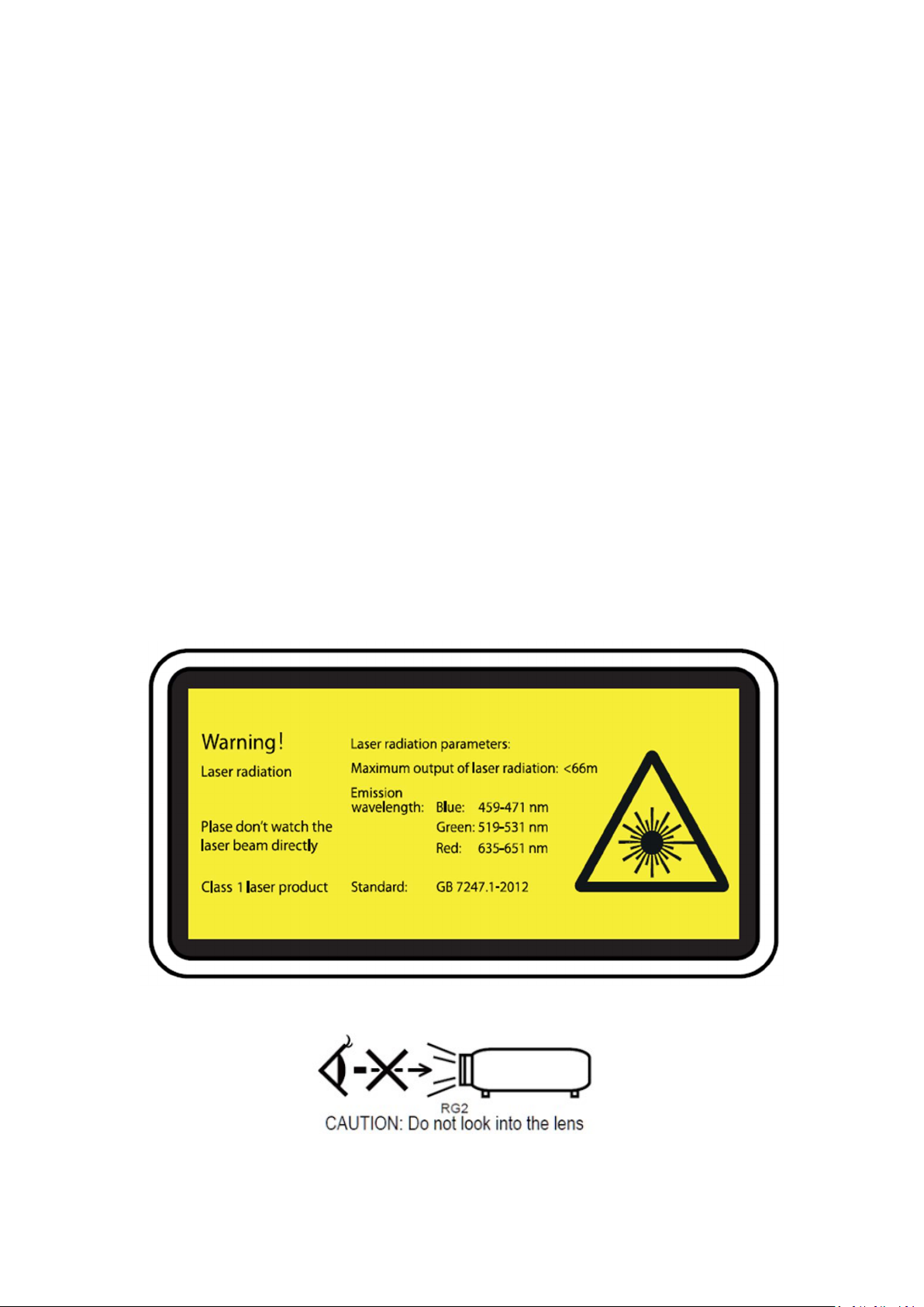
Laser safety parameters of the whole device:
Laser safety standard: Class I laser product, meeting the safety standard of GB 7247.1.2012
Radiation parameters:
Maximum output of laser radiation: ≤ 66mW
Emission wavelength: Blue ray: 459-471nm
Green ray: 519-531nm
Red ray: 635-651nm
Class 1 laser product do not stare into beam. The bright light may result in permanent
eye damage when the projector is on
Warning and explanation label
II
Page 5
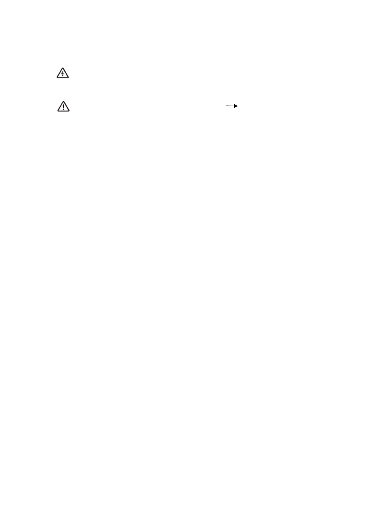
Symbol Descriptions
This triangle pattern with lightning-shaped arrow is a
warning symbol to remind you that the voltage inside
the product is dangerous.
This triangle pattern with exclamation mark is a
warning symbol to remind you of important
instructions related to the product.
· Matters needing attention
Next step
III
Page 6

Important Notes
Please read the following carefully before using this product:
1. Safety Warnings
In case of thunderstorm, please unplug the power plug and the network cable to avoid damage
to the machine.
This product uses the power plug as the power disconnecting device. The socket should be
installed near the product for easy access and sundries cannot be stacked around the socket for the
sake of convenient use.
If you do not use this product for a long time, please unplug the power plug. Do not pull the
power cord when unplugging the power plug.
If you find any abnormal sound or smell, or find that there is only sound but no image on the
machine, please turn off the power immediately, unplug the power plug from the socket, and
contact the after-sales personnel as soon as possible.
Please do not have any object on the power cord and signal wire.
Please do not overload the power socket and ensure that the socket you use is a qualified
product passing national safety certification.
Do not place exposed flame sources (such as lighted candles) on the machine, and keep the
machine away from high-temperature and heating objects.
Do not expose this machine to water droplets or splashes, or place objects filled with liquids,
such as vases, cosmetics or liquid medicines on the machine.
If foreign objects or liquids fall into the machine, please pull out the power plug immediately
and contact the after-sales personnel as soon as possible.
Beware of children standing on or climbing on the machine.
Condensation may occur to the machine after it is moved from a low-temperature area to a
warm area. In order to make the condensation fully dry inside the machine, it should be
powered on after 24 hours.
Do not look directly at the lens after the machine is powered on because the strong light
emitted by the lens may hurt your eyes.
Please do not expose the battery to sunlight, fire and other overheated environment,
otherwise there will be explosion risk.
2. Precautions for Installation and Placement
The product shall be installed by professionals from the manufacturer. The company
disclaims any responsibility for installation errors, product damage or personal accidents
caused by installation by unqualified personnel.
IV
Page 7
The machine should be placed in a flat and stable place, instead of somewhere prone to
shaking.
Please do not place the machine in high-temperature places where there is direct sunlight or
heating devices, places where water, oil and smoke can easily enter the machine, or places
where there is much dust and is moist.
Please do not place the machine in a poorly ventilated or enclosed place.
When the cabinet surface is sprayed with paint or other substances with organic solvent and
grease, the rubber pad of the base may have a slight chemical reaction with it, resulting in
slight corrosion on the cabinet surface. Therefore, we recommend that the user put protective
materials (such as cardboard or glass plate) on the cabinet first before placing the machine.
We recommend that two or more people load, unload and move the machine. When moving it,
please avoid shocks, and especially protect its light-emitting lens.
The engineering plastics, insulating varnish on the internal transformer and rubber parts used
for the shell of the newly purchased product will emit certain smell like newly purchased
furniture, and it becomes stronger when the temperature rises. The smell is determined by the
composition of materials. The material solutions we use fully meet national regulations on
environmental protection, so consumers can use them at ease. The smell will gradually
decrease and eventually disappear during the use of machine. Please keep the environment
ventilated.
The wired network antenna connected to the machine must be isolated from the protective
grounding; otherwise, it may cause fire and other accidents.
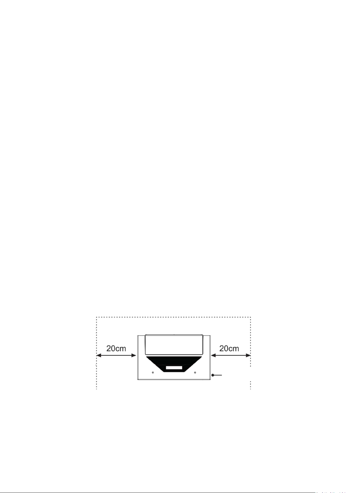
Do not block vents or place sundries on the machine to ensure good heat dissipation effect.
Do not place the machine in a narrow and enclosed space that is not conducive to air
circulation.
The installation is as shown in the figure. Leave a space around the machine for ventilation.
Top view
At a minimum, leave the amount of space shown in the diagram
below for this device to have proper ventilation.
V
Page 8
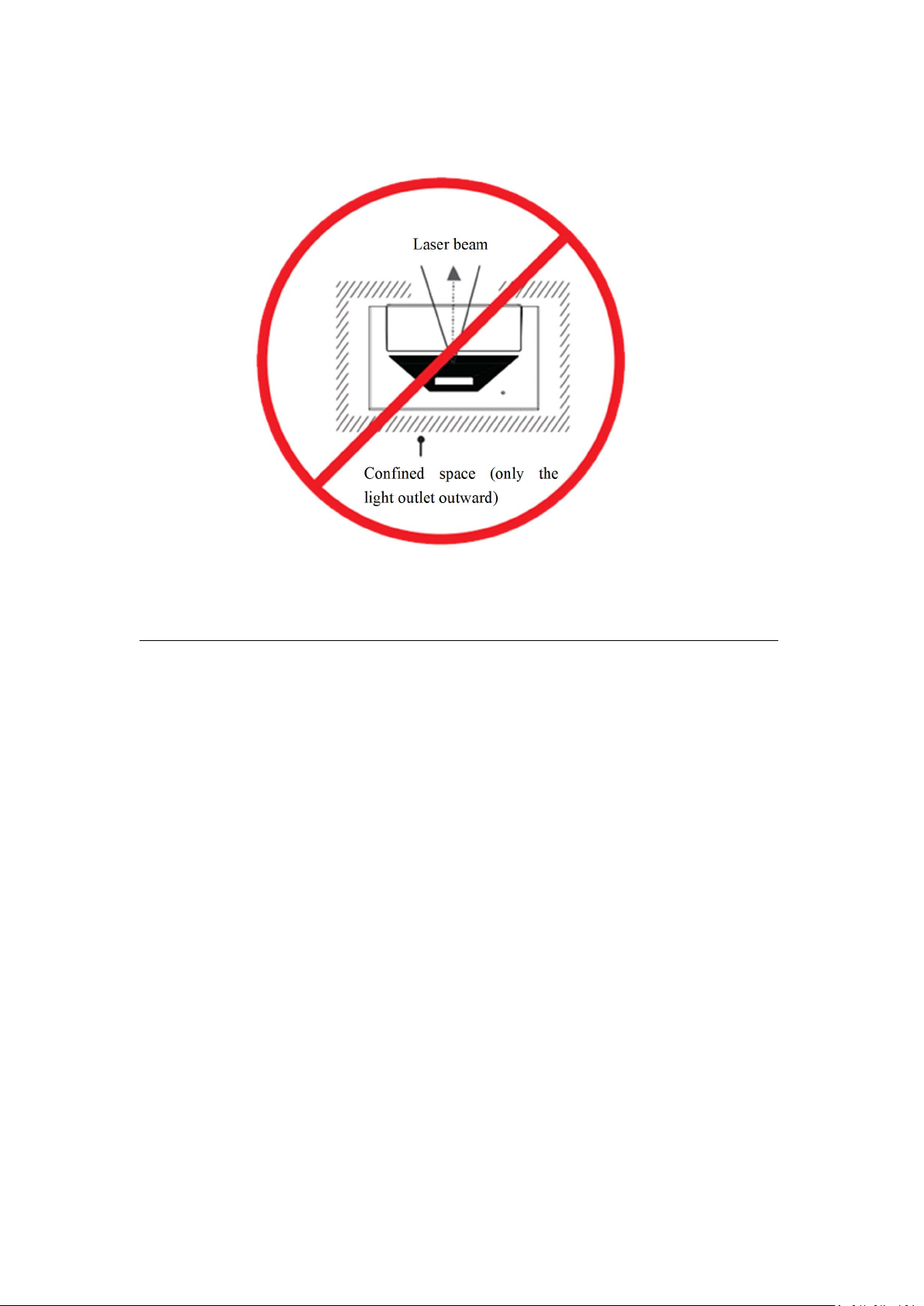
Do not install the machine as shown in the figure below.
Laser beam
Confined space (only the
light outlet outward)
Insufficient ventilation space may cause this device to overheat or become damaged or even fired.
VI
Page 9

3. Precautions for Use
Please do not try to disassemble or repair any part of this device by yourself, which may cause
damage to it and personal injury, and invalidate your product warranty.
If this device gets dirty, please unplug its power plug and wipe it with a semi dried soft cloth
dipped with a small amount of diluted neutral detergent, but do not wipe it repeatedly to avoid
scratching. Do not use alcohol, gasoline, acid, alkali, detergent, volatile oil, diluent and other
solvents to wipe this device because these solvents may deteriorate the materials or damage the
painted surface. If rubber or vinyl products are exposed to this device for a long time, stains may
be caused.
Please do not directly wipe light-emitting lens with your hands, ordinary cleaning paper or
cleaning cloth. For oil stains and fingerprints, please ask professionals to wipe them carefully with
cleaning cloth for optical use, lens wiping paper or professional cleaning solution for the sake of
avoiding damaging the optical coating and affecting the image quality.
Please do not touch the signal connector or reach into the heat dissipation hole with sharp
objects or metal, so as to avoid damage to the product or electric shock caused by short circuit.
Please do not cover this device with articles such as newspapers, tablecloths and curtains, so
as not to hinder ventilation and affect heat dissipation. Otherwise, it may affect the service life of
this device and even cause safety accidents such as fire.
When this device is working or after it is powered off, do not touch the air vent and upper
cover if they are still touched hot.
Please do not cut off the power directly when this device is working. If you need to shut
down this device, please press the standby button on the remote control.
Watch from an appropriate distance. The best distance is 1.5 times the diagonal length of the
screen.
The volume should be kept appropriate, so as not to disturb the neighbors, especially at night.
VII
Page 10
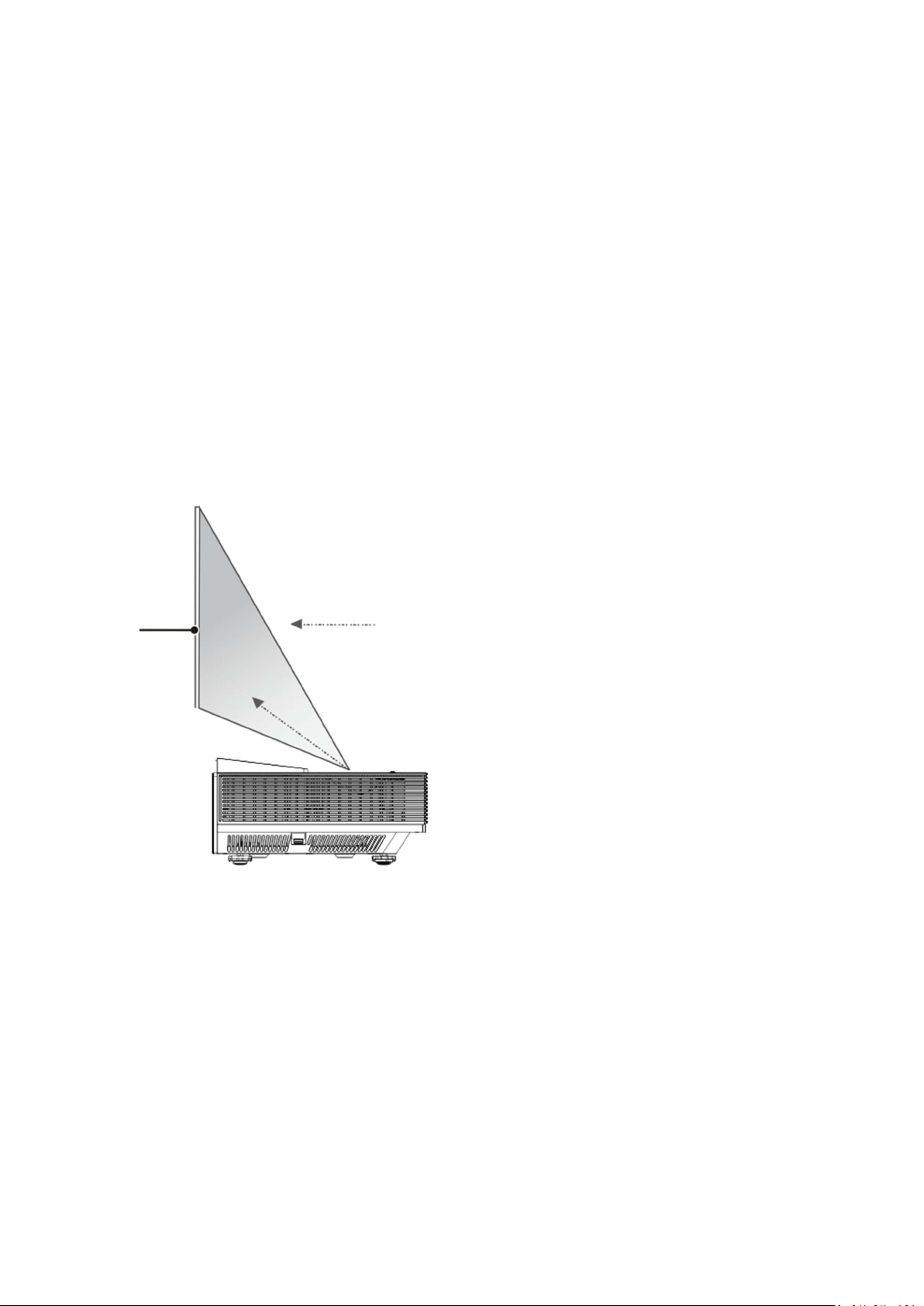
4. Laser
Laser safety parameters of the whole device:
Laser safety standard: Class I laser product, meeting the safety standard of GB 7247.1
Radiation parameters:
Maximum output of laser radiation: ≤ 66mW
Emission wavelength: Blue ray: 459-471nm
Green ray: 519-531nm
Red ray: 635-651nm
Screen
Watching direction
Laser beam
Safety warnings:
This product bears a laser module. Do not disassemble or modify this device in a way not
specified in the user manual, otherwise personal injury may be caused.
Please do not look directly at the laser beam as this is a Class I laser product. If there is a
need to repair it, please wear a laser protective eye mask with OD ≥ 4 and wavelength
ranging from 459 to 651nm
VIII
Page 11

Table of Contents
Device Accessories ............................................................................................................................................. 2
Feet Adjustment to Calibrate the Display Screen ............................................................................................... 3
Settings Adjustment ............................................................................................................................................ 9
Remote Control ................................................................................................................................................. 10
Control Panel .................................................................................................................................................... 13
Introduction to Terminals .................................................................................................................................. 15
Connection Description..................................................................................................................................... 16
First Start ........................................................................................................................................................... 18
OSD menu ......................................................................................................................................................... 19
Miscellaneous ................................................................................................................................................... 25
Specifications .................................................................................................................................................... 28
Ceiling installation……………………………………………………………………………………….……29
Appendices ........................................................................................................................................................ 33
1
Page 12
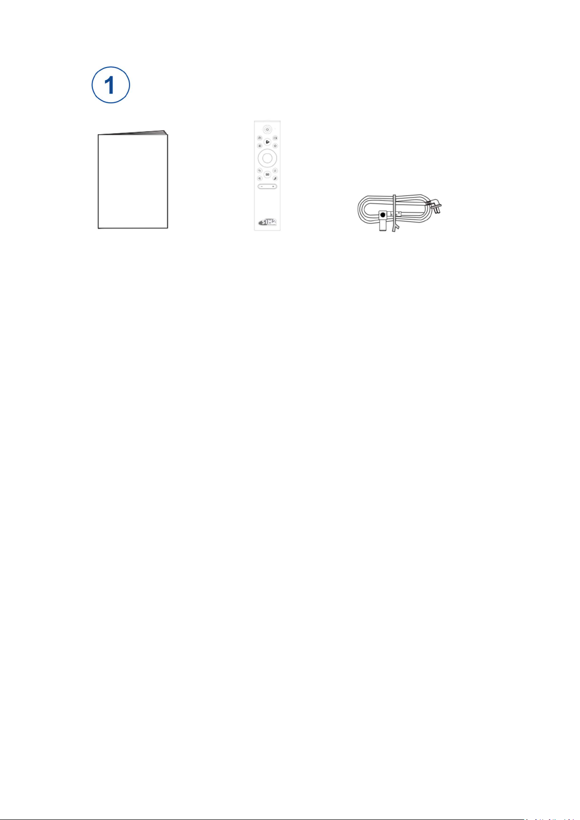
Device Accessories
User
Manual
User Manual * 1 Remote control * 1 Power cord * 1
2
Page 13
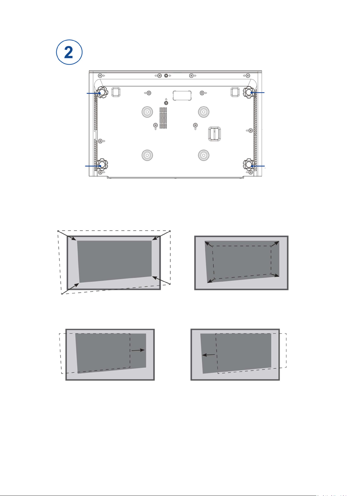
Feet Adjustment to Calibrate the Display Screen
Front foot 1
Back foot 1
Fit the Image to the Screen
[Note] Feet rotation of this device is described from an overlooking view.
Front foot 2
Back foot 2
1. If the image is wider than the
screen, move the projector
forward.
3. If the image shifts to the left
side, move the projector to the
right.
2. If the image is narrower than
the screen, move the projector
backward.
4. If the image shifts to the right
side, move the projector to the
left.
3
Page 14
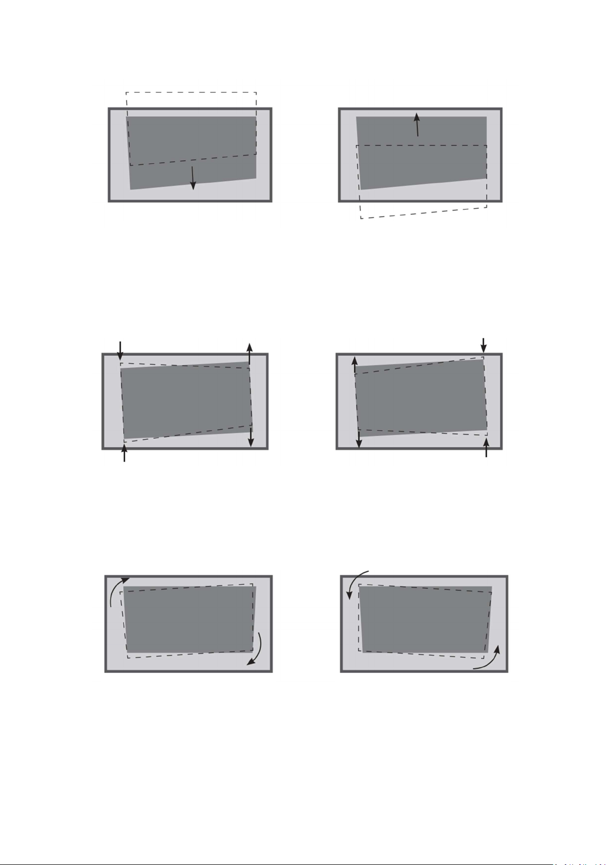
5. If the image shifts to the upper
side, rotate the feet of the
projector clockwise.
6. If the image shifts to the lower
side, rotate the feet of the
projector counterclockwise.
Adjust Length of the Left and Right Side of the Image
1. If the right side of the image is
shorter than the left side, please
rotate the projector clockwise.
2. If the left side of the image is
shorter than the right side, please
rotate the projector
counterclockwise.
Parallel the Bottom of the Image with the Screen
1. If the bottom of the image is
lower on the left and higher on the
right, please rotate the front foot 2
and back foot 2 clockwise and the
front foot 1 and back foot 1
counterclockwise.
4
2. If the bottom of the image is
lower on the right and higher on the
left, please rotate the front foot 2 and
back foot 2 counterclockwise and
the front foot 1 and back foot 1
clockwise.
Page 15
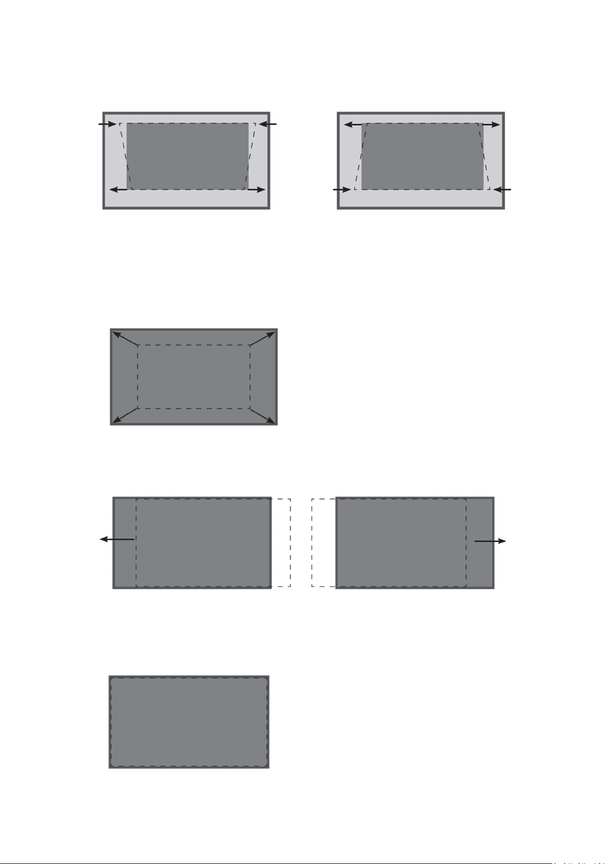
Adjust Length of the Top and Bottom of the Image
1. If the image is longer at the top and
shorter at the bottom, please rotate the back
foot 1 / back foot 2 clockwise or rotate the
front foot 1 / front foot 2 counterclockwise.
2. If the image is shorter at the top and longer
at the bottom, rotate the back foot 1 / back
foot 2 counterclockwise or rotate the front
foot 1 / front foot 2 clockwise.
Enlarge the Image (Rectangle) to Fit the Screen
If the image is narrower than the screen, move the projector backward.
Move the Image (Rectangle) to the Left Move the Image (Rectangle) to the Right
If the image shifts to the right side, move the
projector to the left.
If the image shifts to the left side, move
the projector to the right.
Lock
After fitting the image to the screen, please
keep the projector still to avoid collision.
5
Page 16
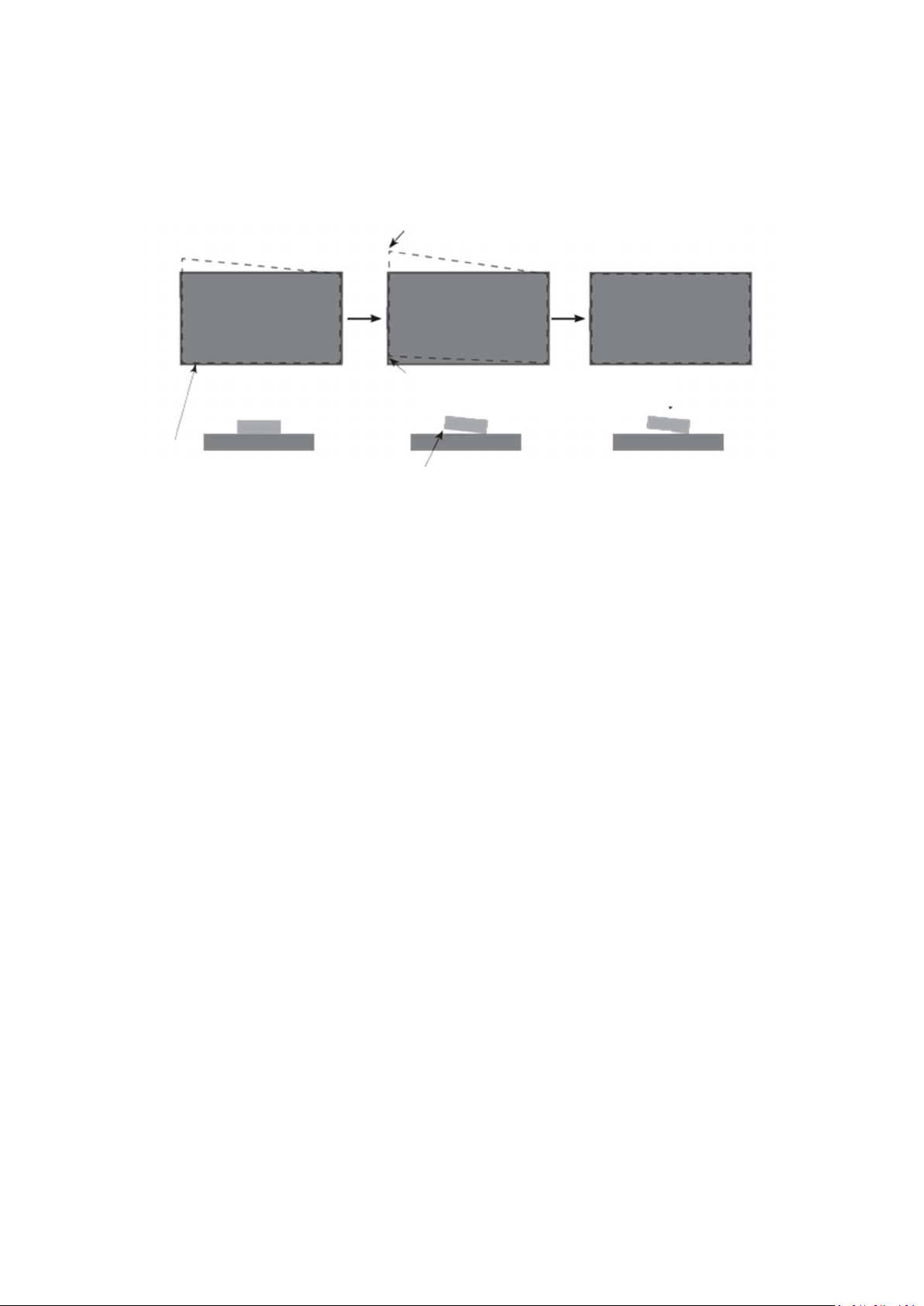
Typical Approaches to Geometric Distortion Adjustment
Adjust the Upper-left Corner of the Image
The situation gets worse after raising left feet
The bottom of the image is slightly
Adjust the image bottom to the same length of the
screen bottom (opening on the inner side of the
frame) and parallel with the screen bottom
Raise left feet of the
1. If the top of the image is higher on the left and lower on the right, please raise the back foot 1
and the front foot 1 by the same height.
2. Rotate the projector clockwise to make image parallel with the screen.
3. If the situation remains after adjustment, please follow the above steps to further raise the back
foot 1 and front foot 1 and rotate the projector clockwise to make image parallel with the screen.
4. If the upper-left corner is inside the screen after adjusting, it means that feet are raised too high.
It is necessary to lower the back foot 1 and the front foot 1 by the same height and rotate the
projector counterclockwise to make image parallel with the screen.
6
Page 17
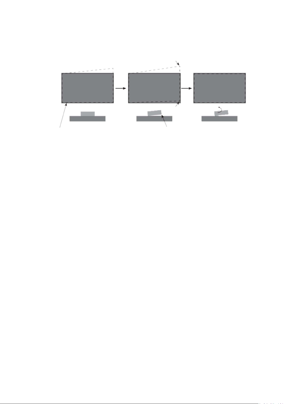
Adjust the Upper-right Corner of the Image
The situation gets worse after raising right feet
The bottom of the image is slightly upward
Adjust the image bottom to the same length
of the screen bottom (opening on the inner
side of the frame) and parallel with the
screen bottom
Raise right feet of the
1. If the top of the image is higher on the right and lower on the left, please raise the back foot 2
and the front foot 2 by the same height.
2. Rotate the projector counterclockwise to make image parallel with the screen.
3. If the situation still exists after adjustment, please follow the above steps to further raise the
back foot 2 and front foot 2 and rotate the projector counterclockwise to make image parallel with
the screen.
4. If the upper-right corner is inside the screen after adjusting, it means that feet are raised too high.
It is necessary to lower the back foot 2 and the front foot 2 by the same height and rotate the
projector clockwise to make image parallel with the screen.
7
Page 18
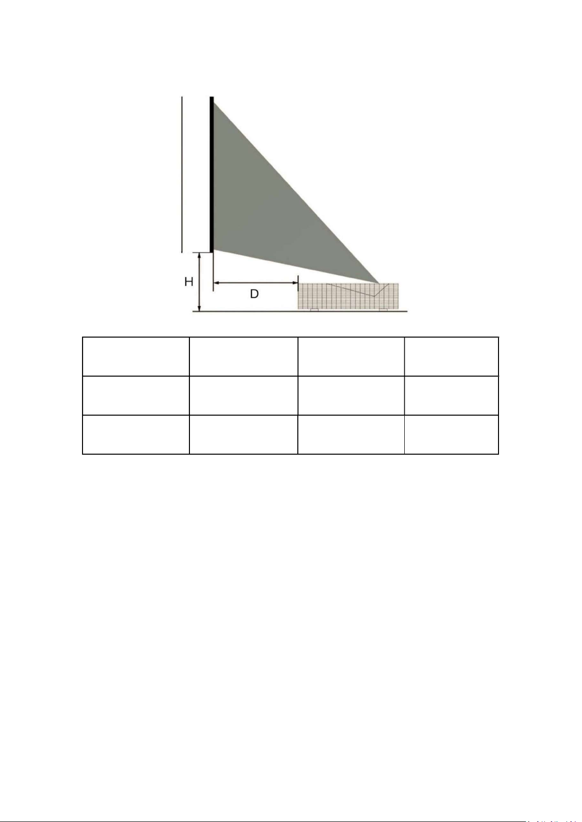
Display Size 100inch 110inch 120inch
H(mm) 352 377 402
D(mm) 245 295 346
* Display size is the diagonal screen
* Due to mechanical tolerances the above numbers could change of ±5%; please consider this
while designing your installation.
H: The “H” is the distance from the bottom of the DTV-S to the lower edge of the screen
W: The “D” is the distance from rear of the DTV-S to the surface of the screen.
In case of ceiling installation refer to page 29.
8
Page 19
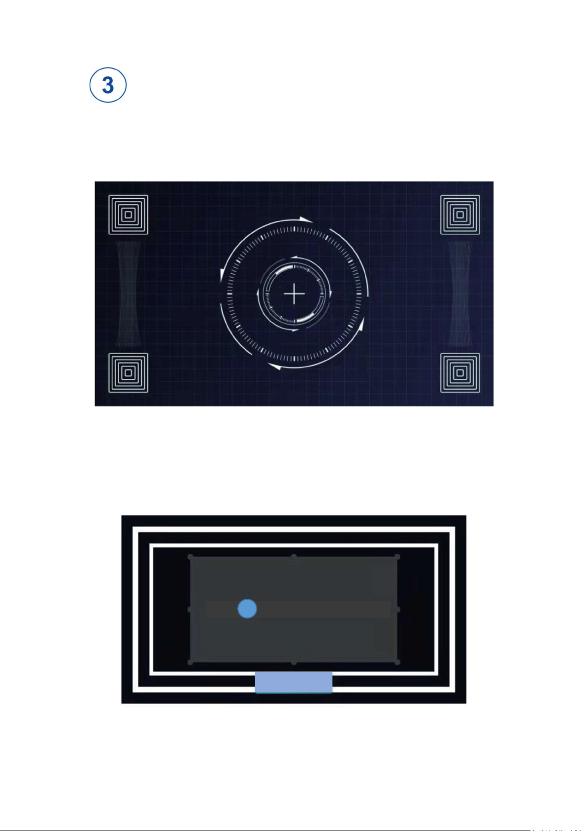
Settings Adjustment
Focus adjustment:
Settings - Optical Machine - Focus, adjust it by pressing Up / Down buttons on the remote control.
Keystone correction:
Settings - Optical Machine - Keystone Correction, select a point for adjustment using Up / Down /
Left / Right buttons.
Press to adjust the selected point
ok
Reset
9
Page 20
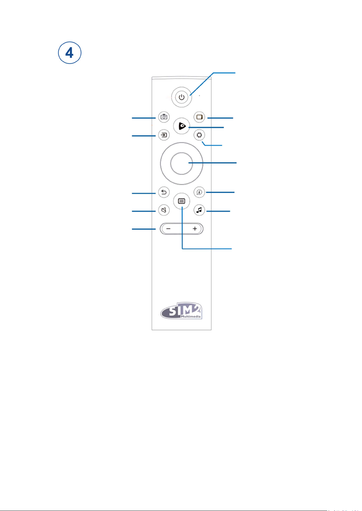
Remote Control
On / Off button
Screen Shot
Signal Resource
Return/Back
Mute
Volume +/-
Display Mode
Media
Settings
OK/ENTER
Info Menu
Audio Settings
Home Main Menu
Pairing Steps
When using the remote control for the first time, press the Home Main Menu button to access the
pairing interface, and then press any key other than Standby of the remote control to start pairing.
[Note]
Pair the remote control with the projector within 3m from the projector when the projector is
powered on.
Generally, the first pairing of the remote control with the projector will be handled by the
service personnel when they come to install the projector for you.
If an unknown error occurs to the remote control, it may be caused by interference. Try to
10
Page 21
remove what’s causing the interference and pair it again.
When pressing the remote control buttons, if the indicator light flashes red, it means that the
remote control is not paired with the projector or the remote control is not paired successfully.
Please press and hold the Menu button for 3 seconds to start pairing and the pairing succeeds
when the blue light flashes 3 times.
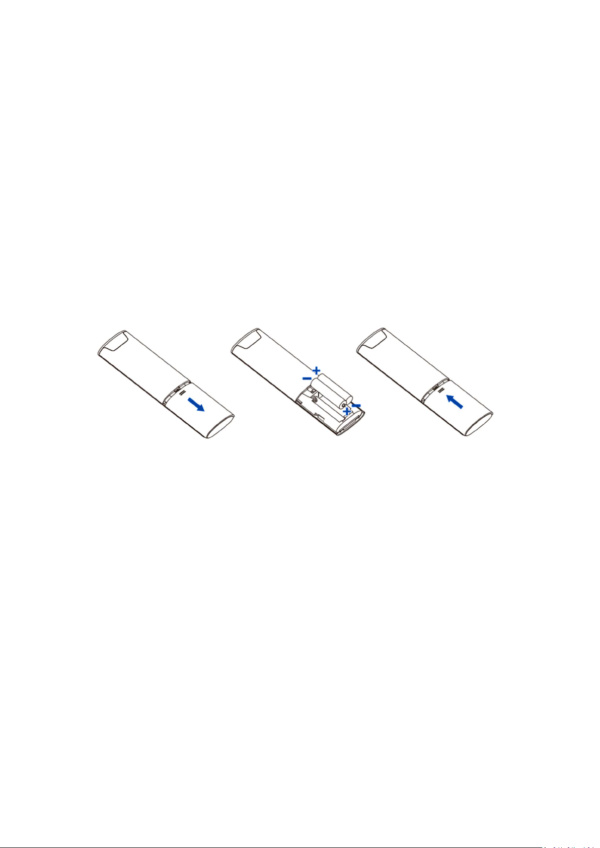
Battery Replacement Method
1. Press the battery cover and push it down.
2. Insert two AAA sized 1.5V alkaline batteries. Make sure to match the (+) and (-) ends of the
batteries with the (+) and (-) ends indicated in the battery compartment.
3. Put the battery cover on from above, and push the battery cover upwards until it is fully
buckled.
Effective Range
1. Remote control distance: The remote control can work at a distance of 8m from the front.
2. Remote control angle: Taking the receiver of the remote control as the apex, the remote control
can work at a 30-degree horizontal or 15-degree vertical angle at a distance of 6m.
Others
1. In view of the wireless nature, the signals of the remote control and receiver may be interfered
and shielded.
2. If an unknown error occurs to the remote control while the battery power is normal, the user can
open the battery cover to take out the batteries, press the OK button for 5 to 10 seconds, and then
put the batteries back in there. The remote control can work normally then.
Matters Needing Attention
1. If the remote control does not operate normally, is unstable or cannot control the projector,
please replace the batteries.
2. If the remote control is not in use for a long time or the batteries run out, please take out the
batteries. (Please handle waste batteries that pollute the environment properly)
11
Page 22
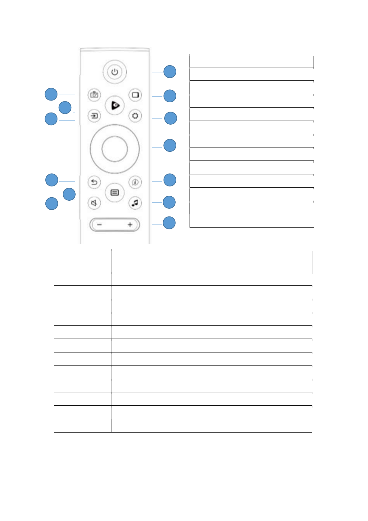
Capture and store on key pen inserted on a USB port the current image
1
2
12
11
10
6
5
4
3
9 8 7
13
1
Screen shot
2
Media
3
Source selection
4
Return
5
Home main menu
Screen shot
on the screen
Media Recall the Media menu
Source selection Select the input signal source
Return Return to previous menu
6
Audio Mute
7
Power on/off
8
Display mode
9
Settings
10
D-pad
11
Info Menu
12
Audio Settings
13
Volume + and -
Home main menu Recall the main menu
Audio Mute Set volume in mute status and restore the audio level
Power on/off Turn on and off the unit
Display mode Change sequentially the “Image Mode” (see Image chapter)
Settings Enter in Settings menu
D-pad Up, down, left, right and Ok buttons for navigation in the menu
Info menu Recall the Info page
Audio settings Change sequentially the “Sound Mode” (see “Audio” chapter.)
Volume + and - Increase and decrease the volume level
12
Page 23
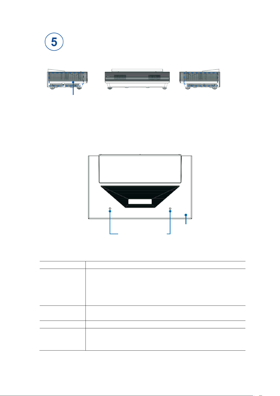
Control Panel
Left view
Air vent
Front view
Remote control receiver
Indicator light
Right view
Air vent
[Note]
There may be protective films on the surface of the upper shell and at the air vents. Please
remove them before starting this device for the first time to avoid damage to it.
Light-emitting lens
Eye protection sensor
Standby button
Name / Button Function Description
Indicator light The indicator light is white when this device is powered on.
During standby, the white indicator light is in the breathing state when the
standby light effect is set to On; the white indicator light is off when the
standby light effect is set to Off.
In case of fault, the indicator light flashes red.
Remote control
receiver
Standby button Power the projector on or off.
Eye protection
sensor
Receive the signal transmitted by the remote control through this receiver.
Under the premise that the eye protection function is turned on, the whole
machine will automatically get its screen closed and give a voice prompt to
protect eyes when the user approaches to the eye protection sensor.
13
Page 24

[Note]
As power failure and system processing take time, please do not switch on and off this device
continuously and quickly, which may cause malfunction.
Arrow buttons may not work on some interfaces and in some applications when operating the
homepage and using the Menu.
If an abnormality occurs during the normal use of the projector, please try to power off the
projector and wait for 2 minutes, and then power it on again.
14
Page 25
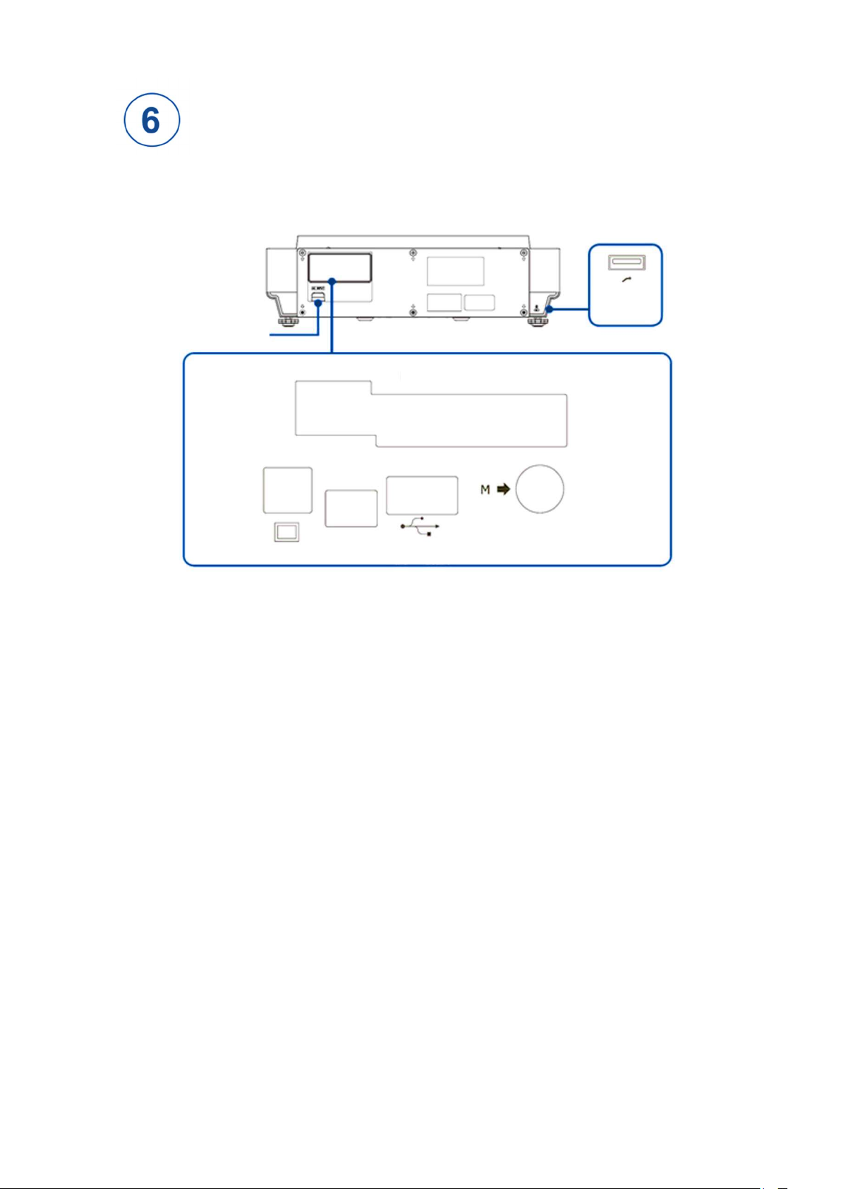
Introduction to Terminals
Rear view
Power input
USB 1
5V 0.5A
HDMI 1
(ARC)
Optical
LAN
Service
HDMI 2
USB 2
5V 0.5A
[Note]
Some external devices may be unable to connect to this device due to specific differences. If this
happens, please use appropriate signal wire or add adapters matching the ports.
Debugging port: for factory debugging only, please do not insert any terminals.
15
Page 26
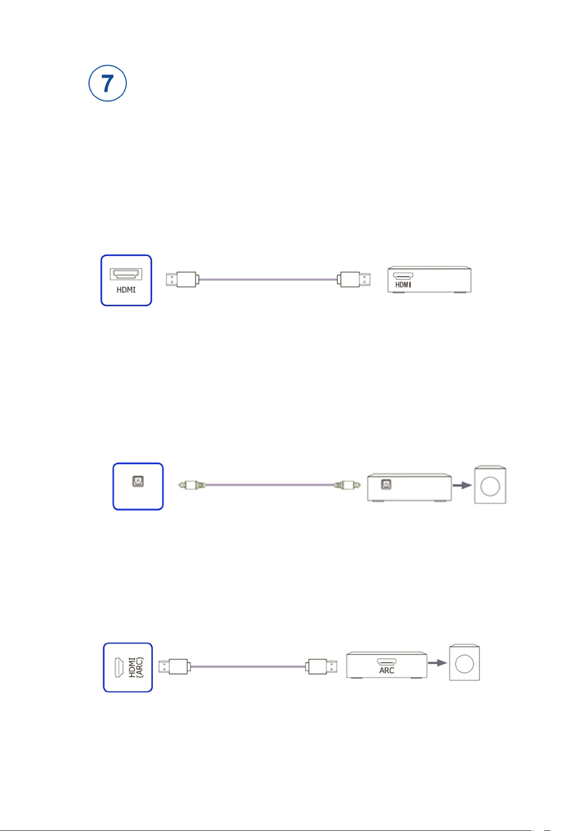
Connection Description
Select Signal Input
Press the Signal Resource button on the remote control to access the Signal Resource menu, and
select the signal resource corresponding to the local port in the Signal Resource menu.
Connect to AV Devices
Connect with HDMI Cable
Set-top box / Player / Computer / DVD
HDMI output
Local port
[Note] Please refer to technical parameters for available signal formats on HDMI ports.
Connect to External Audio Devices
Digital audio output: Connect to the audio amplifier through the optical fiber port, and then
connect to the external speaker through the power amplifier.
Speaker
Optical
Local port
Audio amplifier
Optical
The audio amplifier needs to be connected to the speaker
Audio input
Connect to Devices with ARC (Audio Return Channel) Function
The projector with ARC function can directly transmit the digital audio signal back to external
audio devices via HDMI cables.
Audio amplifier
Speaker
Local port
Audio input
The audio amplifier needs to be connected to the speaker
16
Page 27
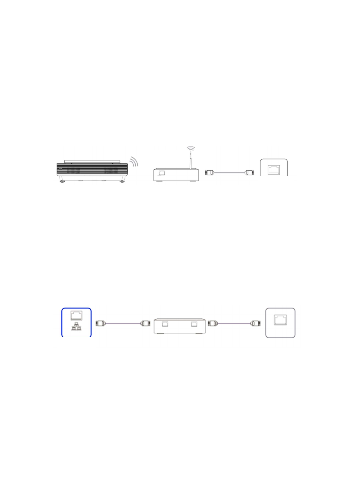
[Note]
If you want to use the ARC function, the audio receiving device connected to the HDMI (ARC)
port of the projector also needs to support the ARC function.
Connect to the Network
Press the Settings button on the remote control to access the settings interface, select the Network,
and press the OK button to access the Network menu
Wireless Network Connection
Wireless
LAN
LAN on the wall
This device can directly receive network signals through wireless router
1. Select Wireless Network in the Network menu, and the list of available wireless networks will
be automatically displayed then.
2. Select an available network, enter the password and click OK. (If the selected network is not
encrypted, you can connect to it directly.)
3. If the network you want to connect to is not displayed in the list, please select Add a New
Network at the bottom of the list, manually enter the Network Name, select the corresponding way
of encryption according to the router settings, enter the password, and click Add.
Wired Network Connection
Router
LAN
Input LAN
Output LAN
LAN on the wall
Local port
Get IP automatically
1. After the network cable is inserted, this device will automatically get the IP address and connect
to the network.
2. If the connection fails, please try again or try to connect by manual input.
Get IP manually
1. Select Network Information in the Network menu.
2. After selecting Manual Input, enter the IP address, subnet mask, DNS server and gateway, and
click Connect.
17
Page 28

First Start
1 Power on / off
Connect the power cord of this device to a 220 V AC power socket.
Press the Standby button on the remote control to turn on this device, and then follow the
navigation prompts after booting to complete settings (the navigation information after
booting is subject to the actual situation).
This device will be in standby state when pressing the Standby button on the remote control
in the power-on state; to return to normal watching, just press the Standby button on the
remote control again.
Please disconnect the power supply when this device is not in use for a long time.
[Note]
After DC shutdown, please restart this device after at least 5 seconds to prevent
abnormalities.
2 Adjust Local Settings
Using the settings function can meet your different needs and make you fully enjoy the
audio-visual effects brought by this device.
You can adjust images and sound, set network connection, etc. here.
Press the Settings button on the remote control to access the settings interface to adjust each
device.
In menus at all levels, you can perform the following operations according to different
menus:
Press Arrow buttons to select items
Press the OK button to confirm operations or access the next menu
Press Left and Right buttons to adjust values
Press Up and Down buttons to adjust options
Press the Return button to the previous menu or exit the Settings menu.
18
Page 29
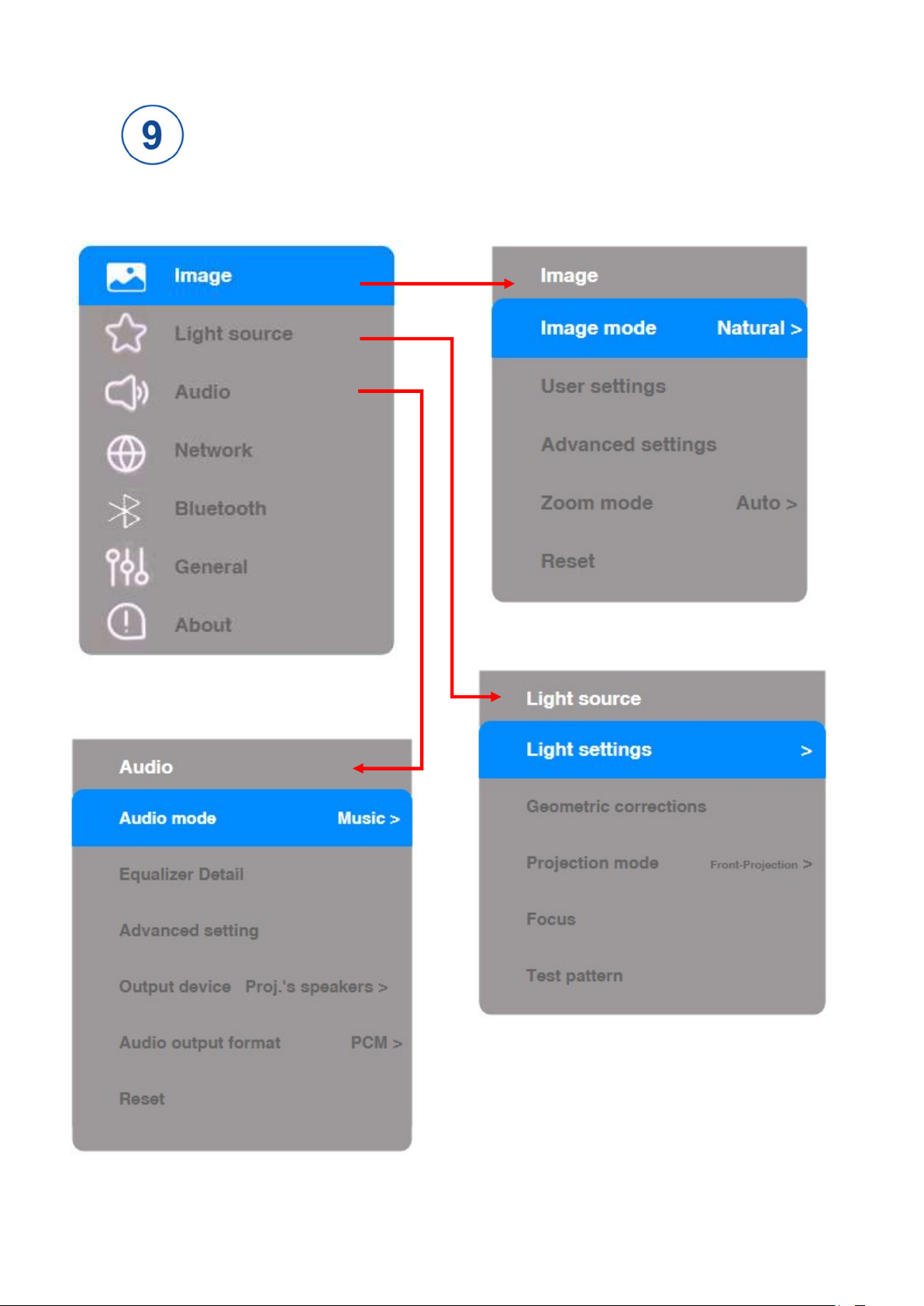
OSD Menu
19
Page 30
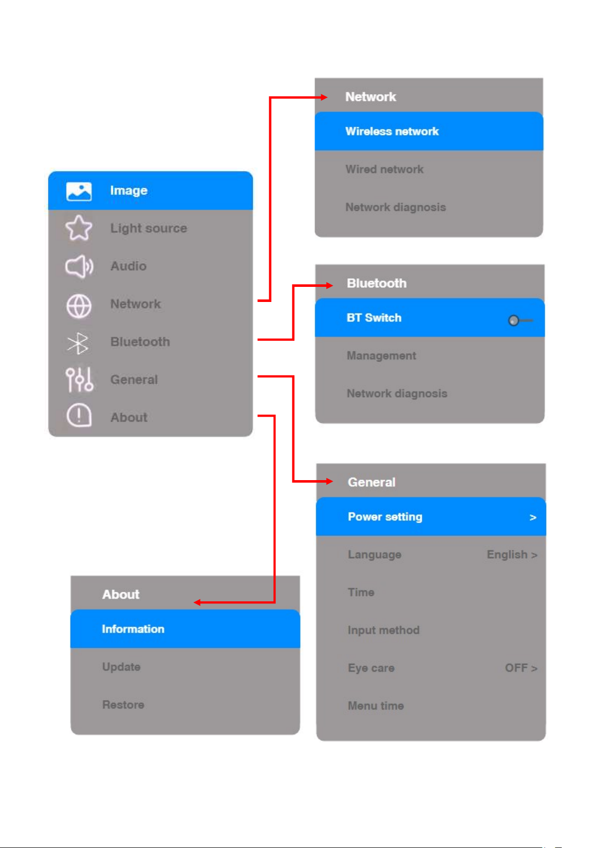
20
Page 31
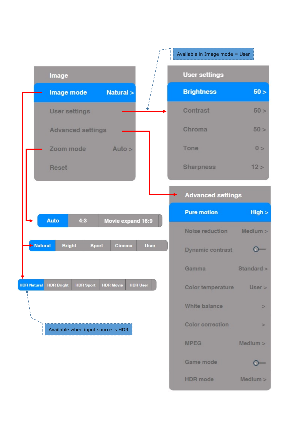
Image
21
Page 32
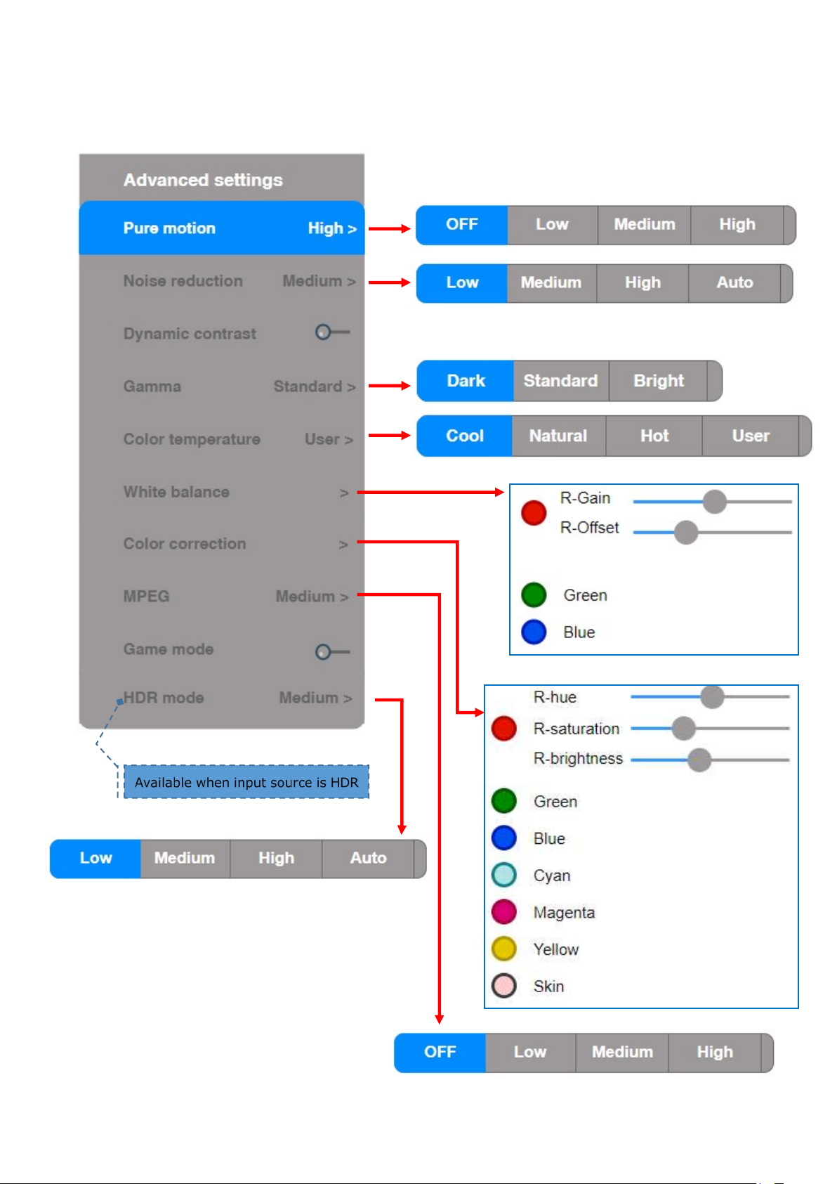
Image – Advanced settings
22
Page 33
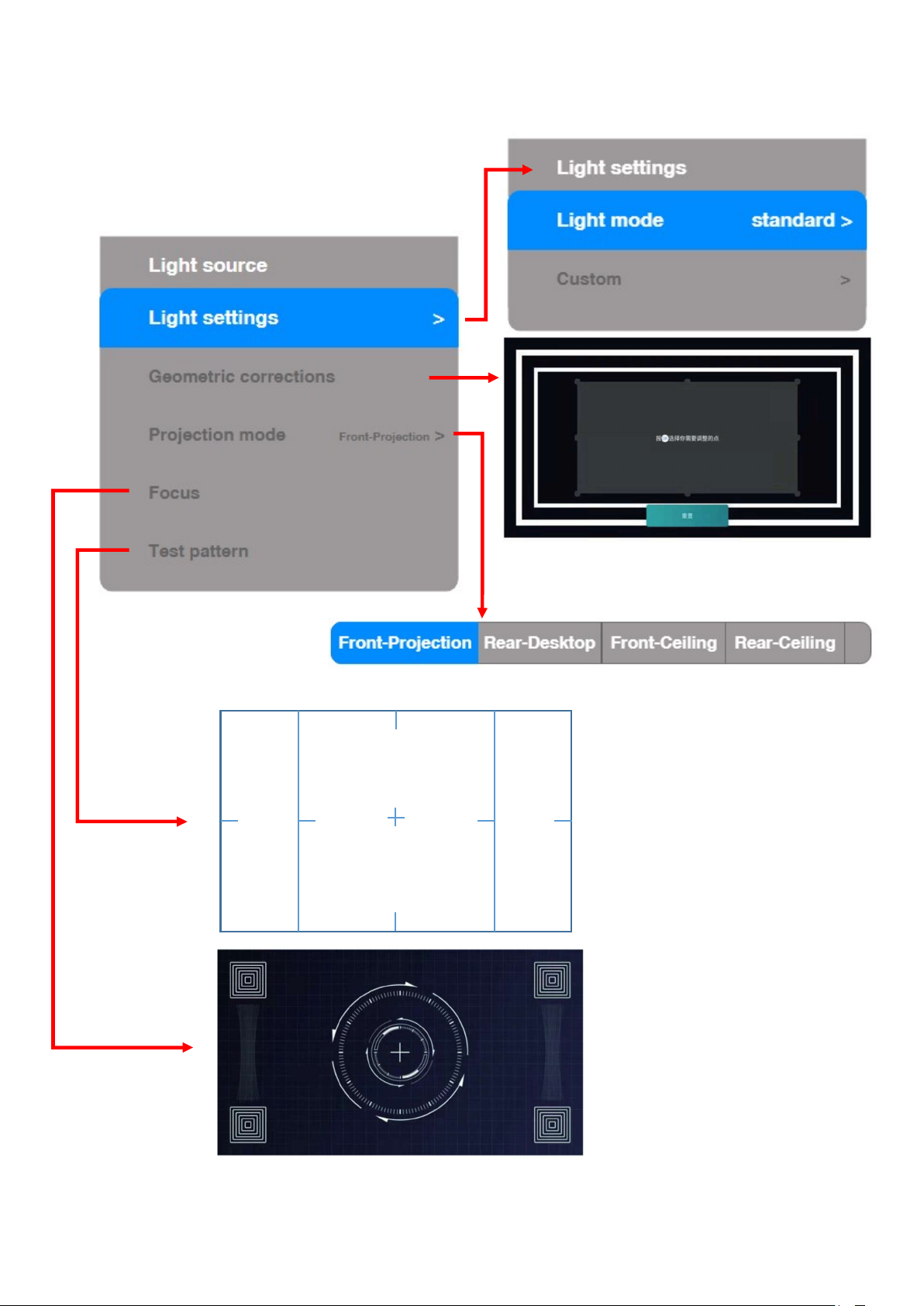
Light source
23
Page 34
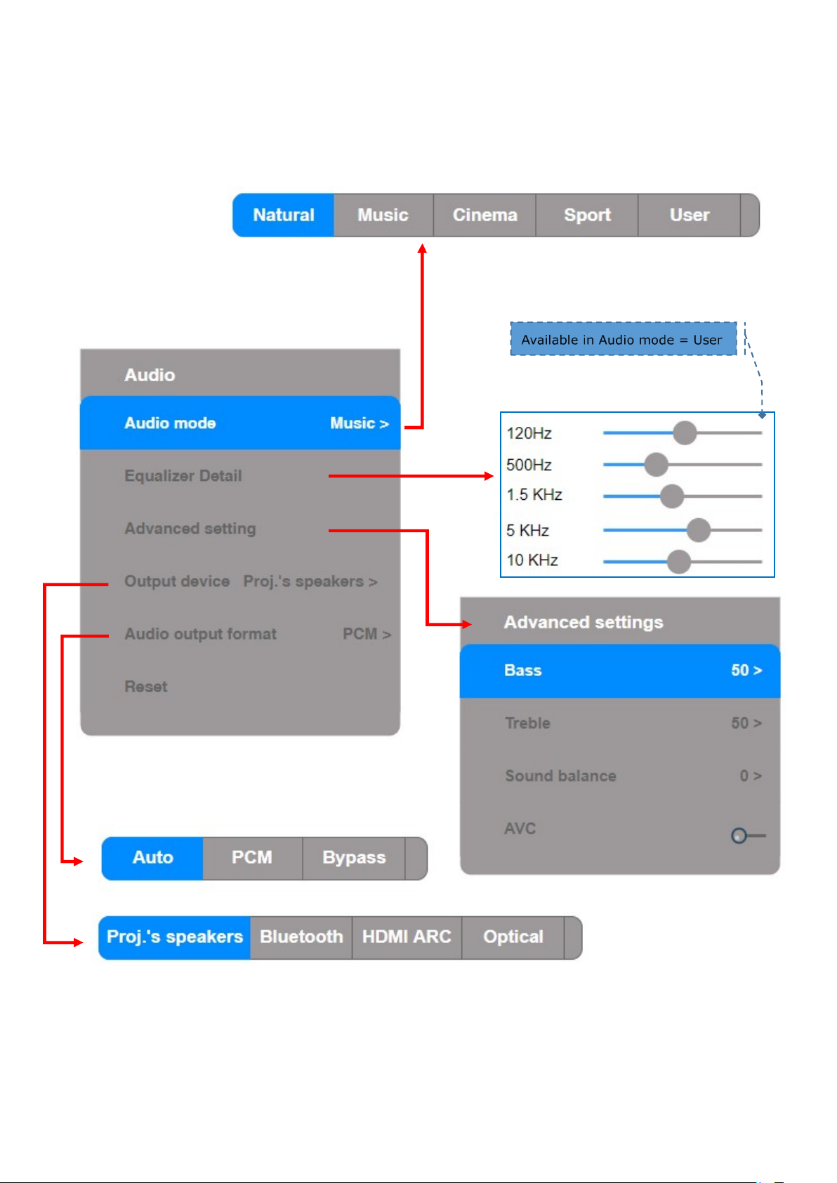
Audio
24
Page 35
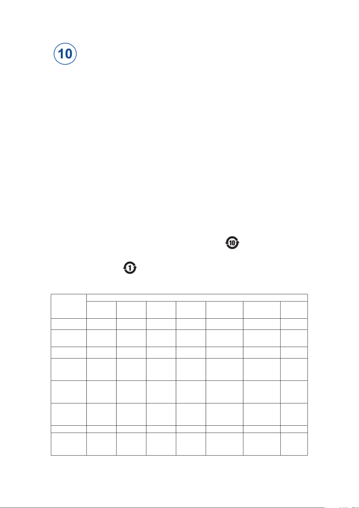
Miscellaneous
Hazardous Substances
Compounds
Compounds
Compounds
C
ompound
s
(PBB)
(PBDE)
Source
Components
Components
Wire
Polymer Parts
Polymer Parts
Battery, etc.)
1 Statement on Environmental Protection
This product meets the environmental protection requirements as prescribed in
Administrative Measures for Limiting the Use of Hazardous Substances in Electrical and
Electronic Products.
Within the environmental protection use period, there will be no leakage of hazardous
substances, precipitation or other problems affecting consumers’ health during their use, so
consumers can use it safely.
Waste recycling tips
When this product is no longer needed or its service life ends, please comply with the relevant
national laws and regulations on the recycling of waste electrical and electronic products and hand
it over to local manufacturers with the recycling qualification recognized by the state for recycling.
Manufacturers that recycle it shall reasonably dispose of parts bearing hazardous substances,
instead of disposing of them at will.
Environmental protection use period
The environmental protection use period of this device is 10 years.
The environmental protection use period of the accessory remote control batteries used together
with this product is 1 year.
Name of Hazardous Substances in the Product and Their Content
Name of Parts
Laser Light
Optical
Machine
Circuit Board
Power Cord
and
Connecting
Non-flame
Retardant
Plastics and
Flame
Retardant
Plastics and
Metal Parts
Accessories
(Remote
Control /
Aluminum
and Its
X O O O O O
X O O O O O
X O O O O O
X O O O O O
O O O O O O
O O O O O O
X O O O O O
X O O O O O
Mercury
and Its
Cadmium
and Its
Hexavalent
Chromium
Polybrominated
Biphenyl
Polybrominated
Diphenyl Ether
Remarks
Only for
part of
models
Only for
part of
models
25
Page 36
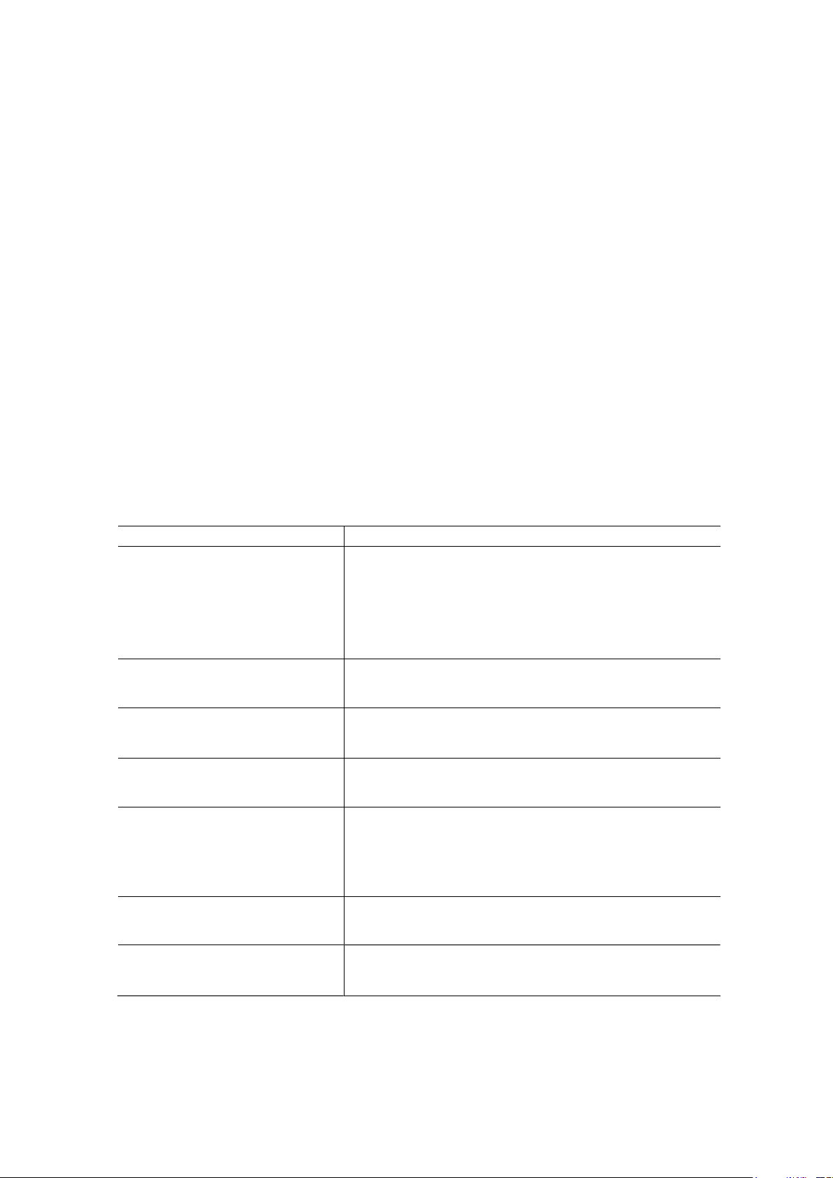
This table is prepared in accordance with SJ / T 11364.
Phenomenon
Solution
O: Indicate that the content of hazardous substances in all homogeneous materials of the part is below
the limit prescribed in GB / T 26572.
X: Indicate that the content of hazardous substances in at least one homogeneous material of the part
exceeds the limit prescribed in GB / T 26572.
The materials identified as X in the table are technically irreplaceable at present. The use of these
materials meets the requirements as prescribed in Administrative Measures for Limiting the Use of
Hazardous Substances in Electrical and Electronic Products and Exception List of Restricted
Substances in Standard Management Directory. We are committed to the R&D and use of advanced
materials and technologies. If technically feasible, we will gradually replace or eliminate these
materials.
2 Simple Fault Solving Tips
Before repairing, please take a look at the table below to see if there are solutions to faults
happening to you.
When you are sure that you can’t solve faults completely according to this instructions, you can
consider contacting professional service personnel for repair.
No sound or image
The image is normal but there is no
sound
No image or black and white image
Sound and image are interfered
The image is blurry or distorted
Horizontal / vertical stripes or
image shake
The device casing “clicks”
Check if the power cord is connected to the wall socket
and if the wall socket is powered.
Check if you have pressed the Power button or the
Standby button.
Check the volume settings or check if Mute mode is set
to On.
Check the volume settings or check if Mute mode is set
to On.
Adjust image settings.
Check the color system.
Turn off or unplug devices that are connected to this
device but are not currently in use.
Observe if light-emitting lens are dirty when this device
is powered off. If so, ask professionals to carefully wipe
them with cleaning cloth for optical use, lens wiping paper or
professional cleaning solution.
Check if there are interference sources nearby, such as
electrical appliances or power tools.
Indoor temperature changes sometimes cause the casing
to expand or shrink, resulting in noise. This is not a fault.
26
Page 37

[Statement]
Pictures and notes in the instructions are for reference only and they may be different from
real products. Specific products in kind prevail. (This statement applies to the entire
instructions)
Service and quality upgrade, and changes to product design and specifications will not be
notified separately.
The software content service applicable to this product depends on the third-party provider.
Some software may not be available due to network, region, service cycle and other reasons,
which has nothing to do with the quality of this product. Please contact the third-party
provider for relevant details.
This product contains ads when booting.
27
Page 38
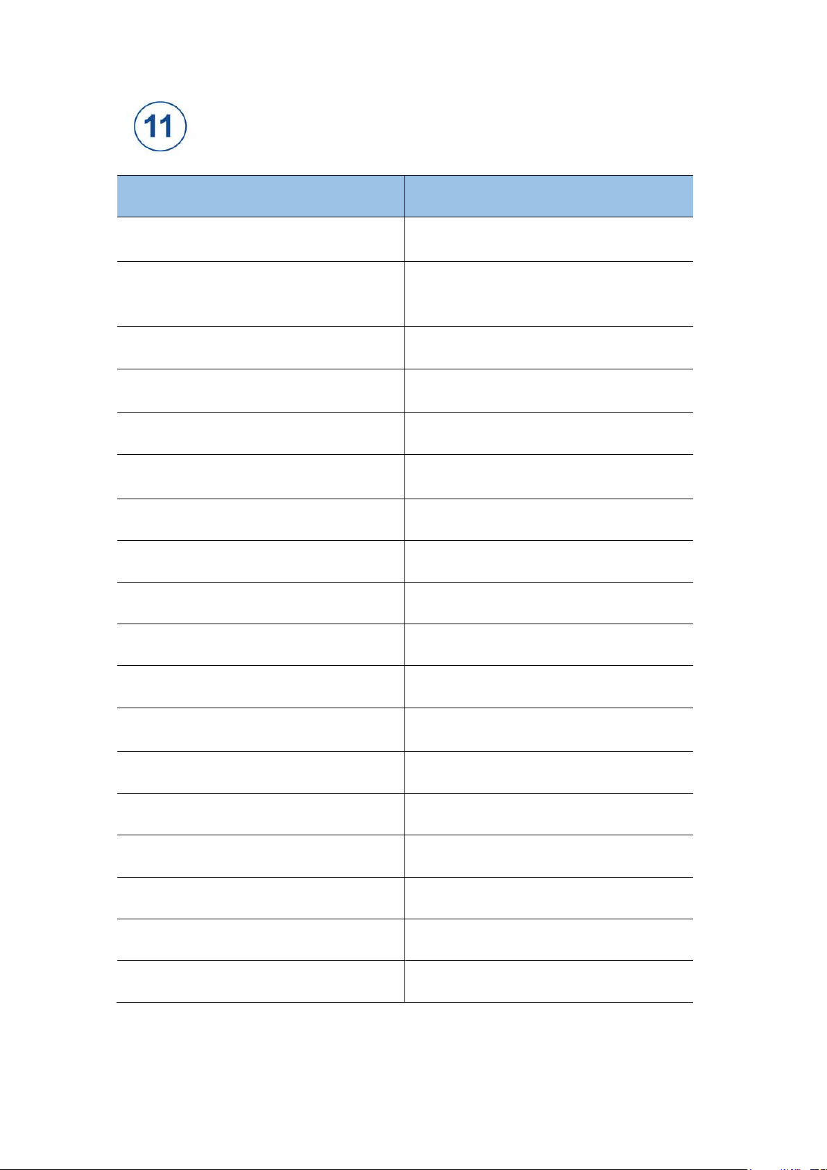
Specifications
Model DTV S
Projection Type
Light source
Focus
Geometry adjustments
Image Resolution
Color gamut
HDR video quality
Contrast:
Brightness
Digital Light Processing (DLP 0.47), 1-chip
DLP Type: 4K, 3840 x 2160
Trichromatic RGB laser system
(expected lifetime approx. 25.000 hours,
watching over 10000 films/2 hours per film)
Motorized - digital adjustments
Dedicated menu for adjust 8 points (H, V):
Keystone, Parallelogram, Pincushion
4K UHD@60Hz
REC 2020
with powerful P7 colors adjustments
Dedicated Display Modes
Adaptive
Up to 2,400 Ansi lumens
Active screen size 90-130inch
Screen resolution VGA (640x480) to 4K UHD (3840x2160)
Power supply
Audible noise
Operating system
AC220V 50Hz 2.0A max,
standby ≤ 0.5W
26dB
Android 9.0
Memory 3GB /128GB
Audio power 10W * 2
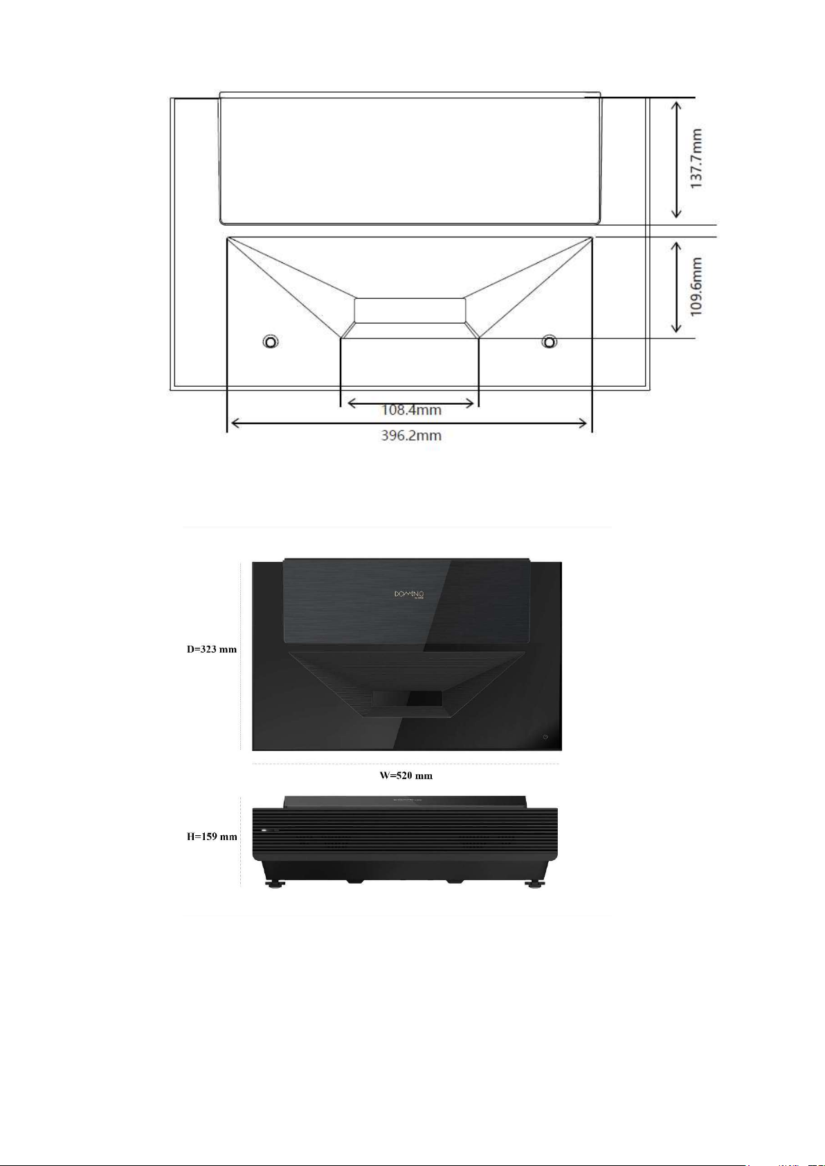
Dimension 520mm * 323 mm * 159 mm
Weight 9.0kg
28
Page 39
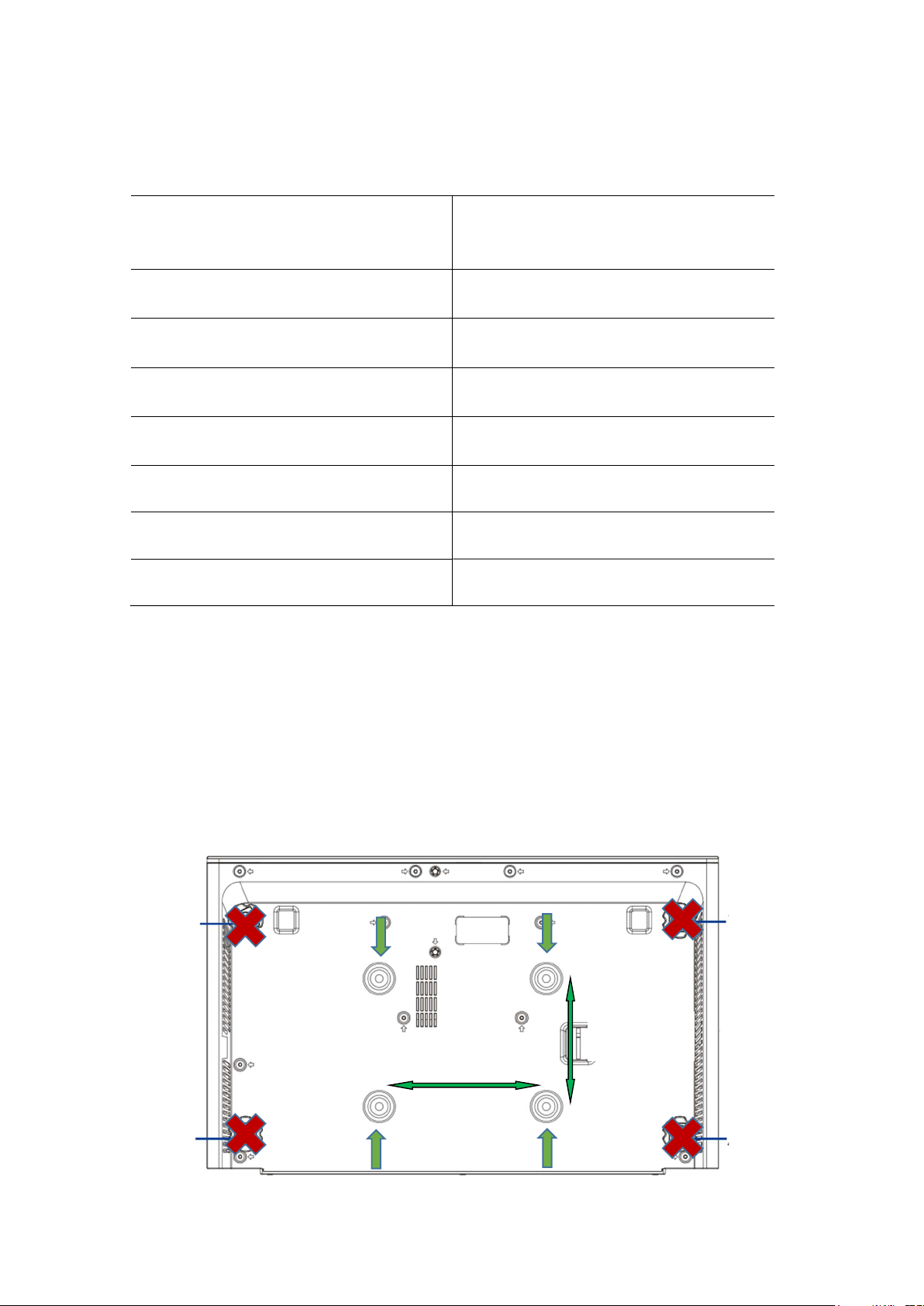
Inputs/outputs
2x inputs HDMI
Audio output
Ethernet
USB 2.0
WiFi
HDMI1/HDMI2 2.0, high speed interface
HDMI1 support the ARC return
4K UHD@60Hz / 1080p@120Hz
Optical fiber
ARC return from HDMI1
RJ45
Internet access and Sw update
2.4G/5G 802.11c
Internet access and Sw update
Hard disk or Flash drive
Audio/Video contents
Bluetooth 4.0
USB 1 5V, 0.5A
M
External audio paring devices
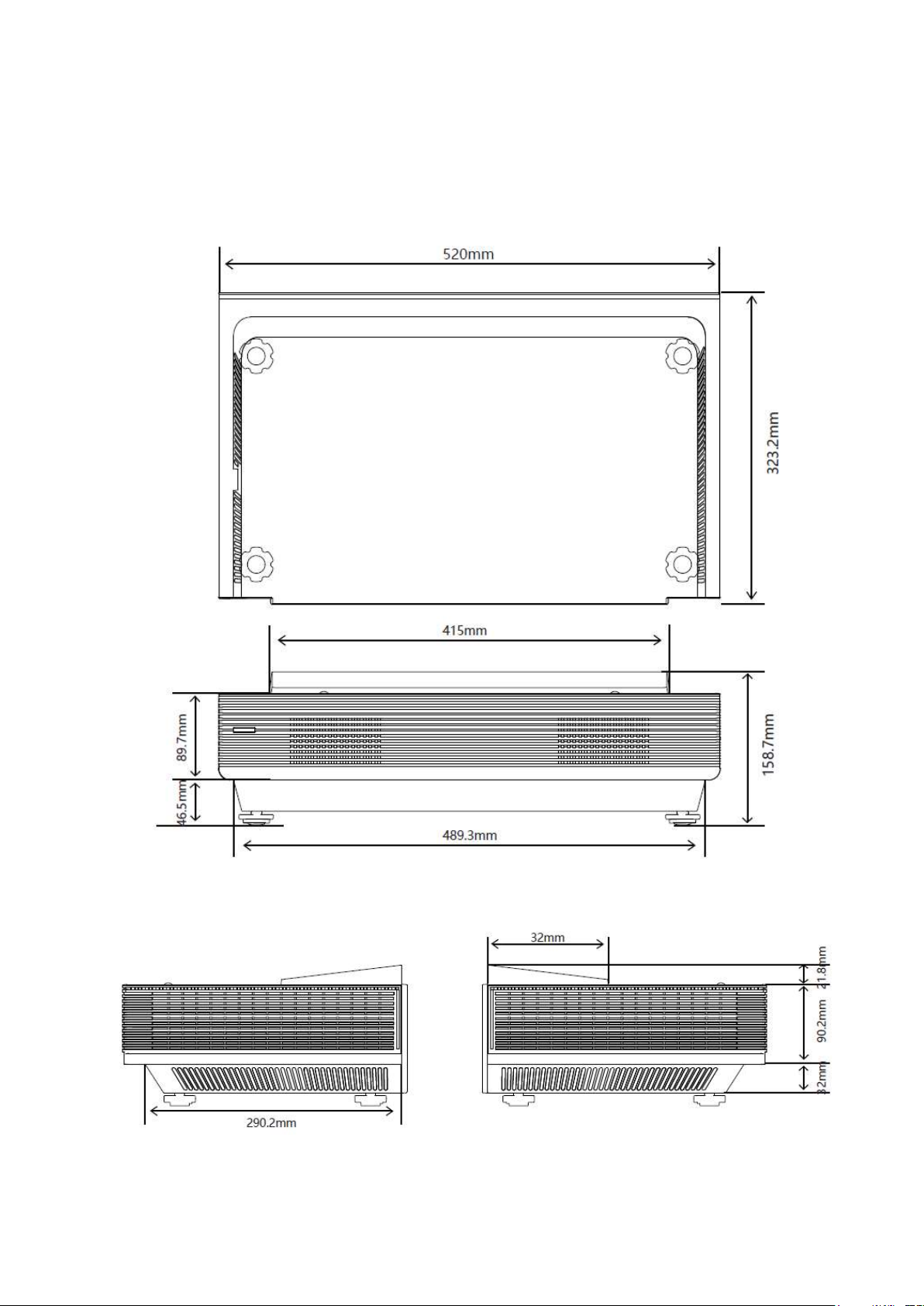
Ceiling Installation
In case of ceiling installation, we recommend using one bracket that allows you tilt and yaw
adjustments; furthermore, forth and back adjustment could be useful to match the image at
screen.
Hang the projector but using the four holes in the center of underneath panel:
170 mm X 130 mm. DO NOT use feet.
170 mm
29
130 mm
Page 40
Dimensions
30
Page 41
31
Page 42
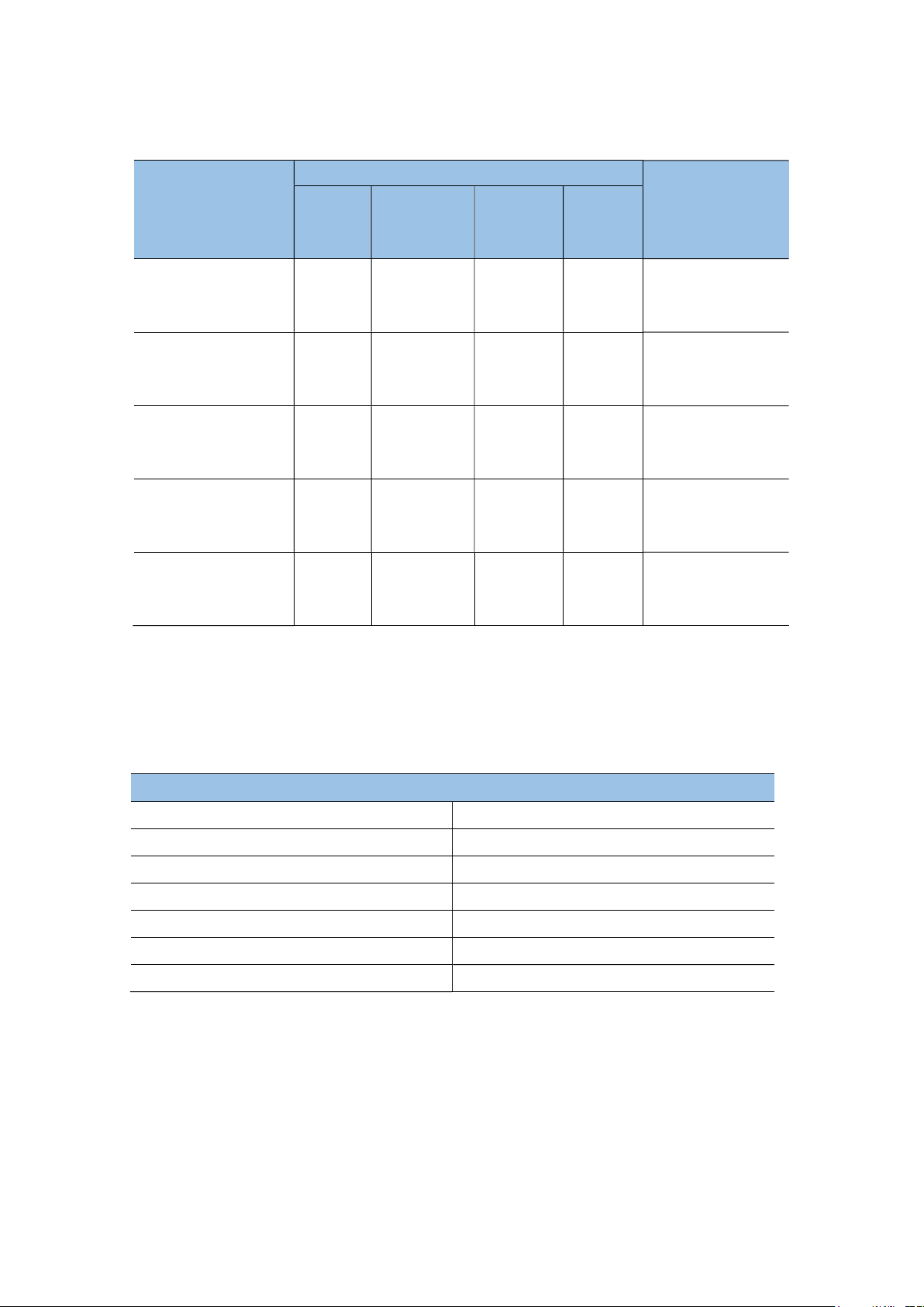
Video formats available are shown below:
Video Decoding
Encapsulation
Type
.avi Xvid 1920x1080 40Mbps 60fps
.avi .mpg .ts MPEG 2 1920x1080 80Mbps 60fps
.ts .mkv .avi .mp4 .flv H.264 4096x2160 135Mbps 60fps
.avi .mkv .mov MPEG 4 1920x1080 40Mbps 60fps
.ts .mkv .mp4 H.265 4096x2160 100Mbps 60fps
Resolution
(Max)
Bit Rate
(Max)
Frame
Rate
(Max)
Audio Decoding
Dolby Audio,
MPEG1 (Layer 1,
2, 3)
Dolby Audio,
MPEG1 (Layer 1,
2, 3)
Dolby Audio,
AAC, MPEG1
(Layer 1, 2, 3)
Dolby Audio,
MPEG1 (Layer 1,
2, 3)
Dolby Audio,
AAC, MPEG1
(Layer 1, 2, 3)
[Note]
Dolby Audio: Dolby Digital, Dolby Digital Plus and Dolby AC4 are available.
Due to different video production tools, this device cannot guarantee to get all the listed
formats available.
Signal Formats Available on HDMI Port
RGB / 60Hz 640x480, 800x600, 1024x768
YUV / 50Hz 576i, 576p, 720p, 1080i, 1080p
YUV / 60Hz 480i, 480p, 720p, 1080i, 1080p
YUV / 24Hz 25Hz 30Hz 3840x2160, 4096x2160
YUV420 / 50Hz 60Hz 3840x2160, 4096x2160
YUV444 / 50Hz 60Hz 3840x2160, 4096x2160
RGB444 / 50Hz 60Hz 3840x2160, 4096x2160
[Note]
HDMI2.0 and HDMI1.4 (default) are available on this device. Some of the above signal formats
are available on HDMI1.4, while all of the above signal formats are available on HDMI2.0. In
case of a necessity to use HDMI2.0, press the Menu button under the HDMI channel and select
HDMI version as HDMI2.0 or HDMI Plus
32
Page 43
Appendices
Regulation & Safety Notices
This appendix lists the general notices of your projector.
Notice: Shielded cables
All connections to other computing devices must be made using shielded cables to maintain
compliance with FCC regulations
Caution
Changes or modifications not expressly approved by the manufacturer could void the user’s
authority, which is granted by the Federal Communications Commission, to operate this
projector.
Operation conditions
This device complies with CCC Rules. Operation is subject to the following two conditions:
1. This device may not cause harmful interference.
2. This device must accept any interference received, including interference that may cause
undesired operation.
Notice: Canadian users
This Class B digital apparatus complies with Canadian ICES-003.
Remarque à l’intention des utilisateurs canadiens
Cet appareil numerique de la classe B est conforme a la norme NMB-003 du Canada.
Declaration of Conformity for EU countries
• EMC Directive 2004/108/EC (including amendments).
• Low Voltage Directive 2006/95/EC.
• R & TTE Directive 1999/5/EC (if product has RF function).
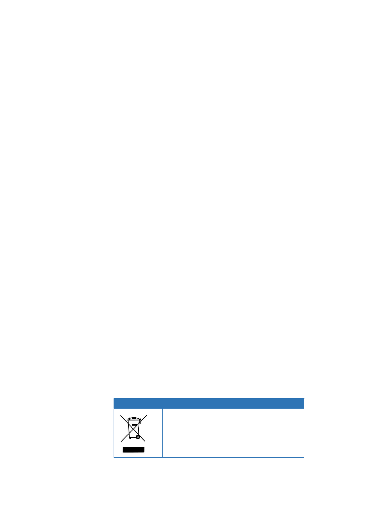
Disposal Instructions
Do not throw this electronic device into the trash
when discarding. To minimize pollution and
ensure utmost protection of the global
environment, please recycle it.
33
Page 44

Trademarks
• DLP is trademark or registered trademark of Texas Instruments.
• HDMI, the HDMI Logo and High-Definition Multimedia Interface are trademarks or
registered trademarks of HDMI Licensing LLC.
• Other product and company names mentioned in this user’s manual may be the
trademarks or registered trademarks of their respective holders.
34
Page 45

SIM2 MULTIMEDIA S.r.l.
Registered Office:
Via Gorizia 10,
33170 Pordenone, Italy
Business Address:
Via Udine No 59
33061 Rivignano Teor (UD) – ITALY
Phone: + 39 0434 383292
Fax: +39 0434 383260
Email: [email protected]
www.sim2.com
SIM2 USA
SIM2 USA Inc.
10216 NW 47th Street
Sunrise, FL 33351
Phone: +1 (954) 442 2999
Email: [email protected]
www.sim2usa.com
SIM2 BRIONVEGA Co., Ltd
Room 303-304, No. 244 Liaoning Road
Shanghai 200080 – CN
Phone/Fax: 86-21-62881991
Email: [email protected]
(EN/1.8)
35
 Loading...