

Page 1

Pioneering computer case with exceptional style and functionality
Page 2

Page 3
Installation and system optimization guide:
The following manual and guides were carefully prepared by the SilverStone engineering team to
help you maximize the potential of your SilverStone product. Please keep this manual for future
reference when upgrading or performing maintenance on your system. A copy of this manual can also
be downloaded from our website at:
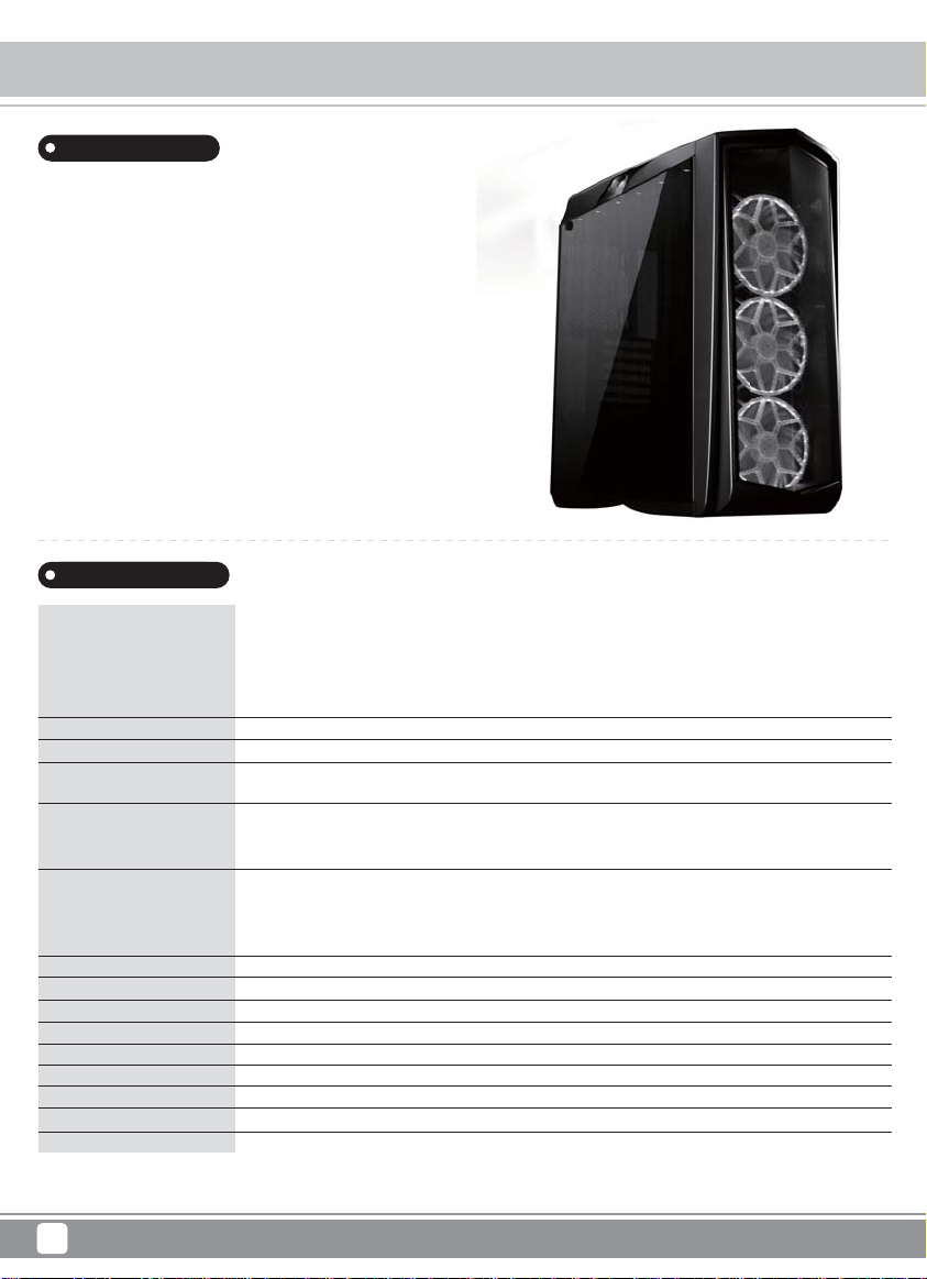
Product Overview
Specification
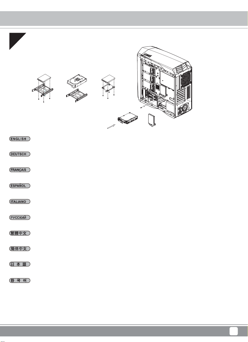
Disassemble Chart
Installation Guide
Top Cover Removed Guide
Connector Definition
Component size limitations
Upqrade And Mainterance
Fan removal guide
Fan filter purchase process
P.1
P.1
P.2
P.4
P.17
P.18
P.24
P.28
P.29
P.30
Warranty Information
Page 4
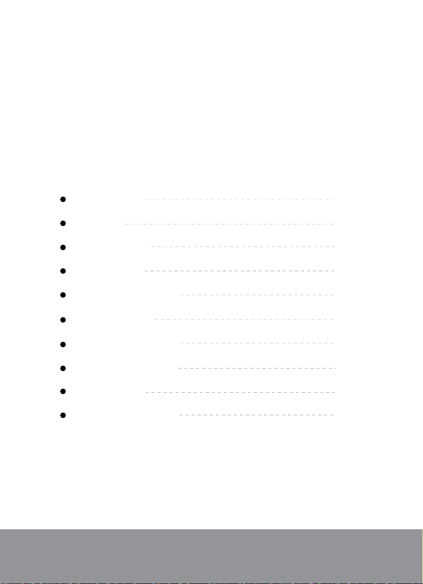
Primera Series PM01-RGB / PM01-FX
Product Overview
Introduction
Primera is the Spanish word for “first” or “first class.” Cases in this
series are designed for those seeking to build PCs with rich feature
set and trend-setting aesthetics.
The PM01-RGB is an incredible computer case that advances the
original PM01 design, a case that was among the top performing
cases released in 2016. It substitutes single color LEDs with RGB
variants and has a full tempered-glass side panel to make PM01-RGB’s
supercar inspired design feel even more luxurious and dazzling.
Besides standard RGB light strips, the case includes SilverStone’s
exclusive RGB fan guards that can change colors and lighting modes
easily via LED control button on the top panel, or by compatible
motherboard’s software utility. For those looking to get a case that
can deliver cooling performance as good as it looks and want deeper
personal customization, the PM01-RGB is it!
Specifications
Model No.
Material
Motherboard
Drive Bay
Cooling System
Radiator Support
Expansion Slot
Front I/O Port
Power Supply
Expansion Card
Limitation of CPU cooler
Limitation of PSU
Net weight
Dimension
Others
* For 280mm radiators and fans, total thickness may not exceed 33mm depending on motherboard component clearance.
** For more details on RGB control, please refer to instruction manual.
SST-PM01B-RGB (black + RGB LED + window)
SST-PM01C-RGB (matte black + RGB LED + window)
SST-PM01W-RGB (white + RGB LED + window)
SST-PM01B-FX (black with RGB LED + graphics side panel + window)
SST-PM01W-FX (white with RGB LED + graphics side panel + window)
Plastic outer shell, steel body, tempered glass side panel
ATX (up to 12" x 10.7"), Micro ATX
External
Internal
Front
Top
Rear
Front
Top
Rear
Bottom
7
USB 2.0 x 2, USB 3.0 x 2, Audio x 1, MIC x 1
Standard PS2 (ATX)
Support graphics card up to 16.5" (419mm), width restriction - 6.88" (174mm)
180mm
240mm
10.1kg
220mm (W) x 571mm (H) x 560mm (D), 70.3 Liters
Built-in RGB LED controller**
--
2.5" or 3.5" x 4, 2.5" x 5
3 x 120mm / 140mm fan slot (includes 3 x 140mm fan + RGB LED fan guards)
3 x 120mm fan slot or 2 x 140mm fan slot
1 x 120mm / 140mm fan slot (includes 1 x 140mm fan)
2 x 120mm ; 1 x 240mm / 280mm / 360mm
2 x 120mm ; 1 x 240mm / 280mm / 360mm*
1 x 120mm / 140mm
N/A
1
Page 5
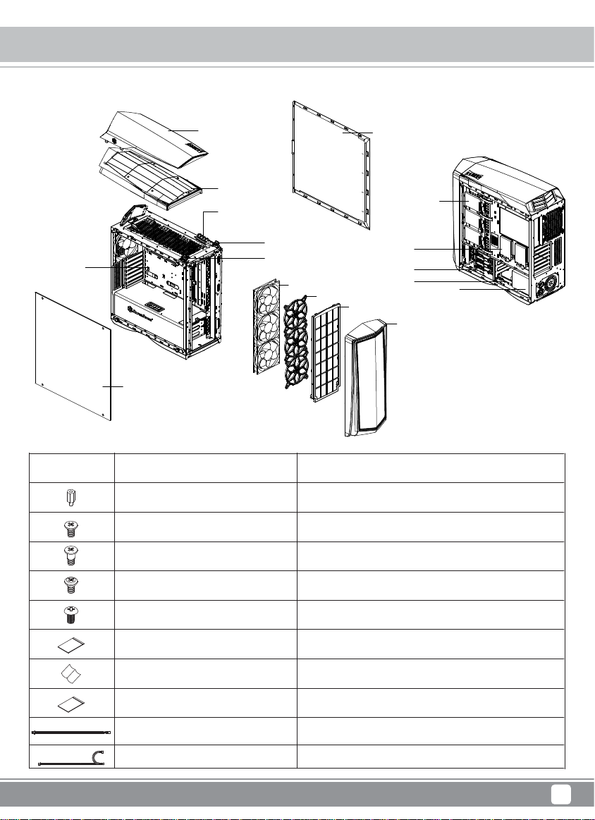
Primera Series PM01-RGB / PM01-FX
Disassemble Chart
ATX MB (OPTION)
Picture Item
TOP-COVER
LEFT-SIDE-PANEL
Screw A 6.6mm
Screw B
TOP-PANEL
USB 3.0 X 2, USB 2.0 X 2
AUDIO & MIC PORT
LED BUTTON
POWER BUTTON
RIGHT-SIDE-PANEL
2.5" HDD X 3
2.5" HDD X 2
2.5" or 3.5" HDD X 3
LED FAN X 3
2.5" or 3.5" HDD X 1
RGB LED FAN GUARDS X 3
FRONT-FILTER
FRONT-PANEL
PSU (OPTION)
Purpose
Motherboard Standoff
Secure Motherboard, PSU, 3.5" HDD
Screw C
Screw D M3
Screw E M3 6.5mm
Zipper bag 120 x 90mm
Manual
Zipper bag 170 x 240mm
Signal cable
Extension cable
Secure 3.5" HDD
Secure 2.5" HDD
Secure HDD tray
Packing all screws
Installation Guide
Packing all items
RGB 4pin signal cable
RGB extension Y cable
2
Page 6
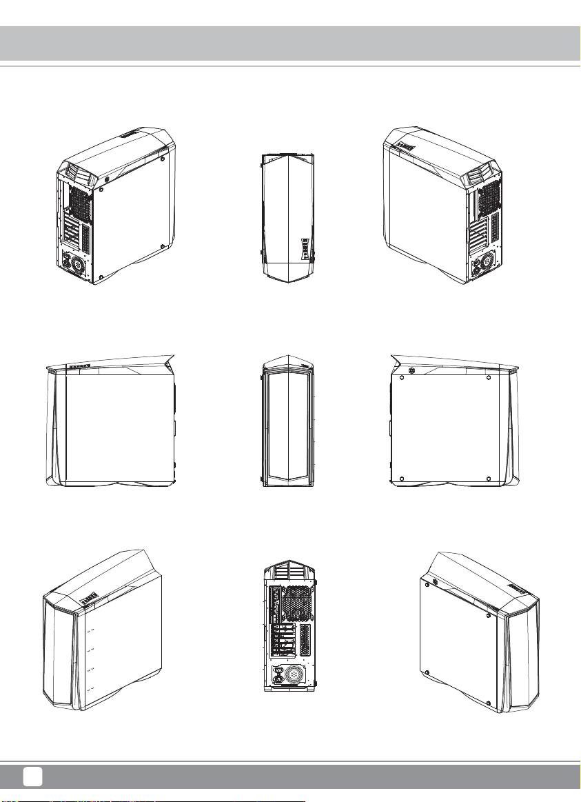
Primera Series PM01-RGB / PM01-FX
Disassemble Chart
TOP REAR RIGHT 3/4REAR LEFT 3/4
LEFT SIDE
3
FRONT
REAR
RIGHT SIDE
TOP RIGHTTOP LEFT
Page 7
Primera Series PM01-RGB / PM01-FX
Before you begin, please make sure that you
1
Have all components collected.
2
Check that all components do not have compatibility problems with each other or with the case.
3
If possible, assemble the components outside the case first to make sure they are working.
Keep the motherboard manual ready for reference during installation.
4
Prepare a Philips screwdriver.
5
6
Be careful not to strike on glass side panel when removing it from the case.
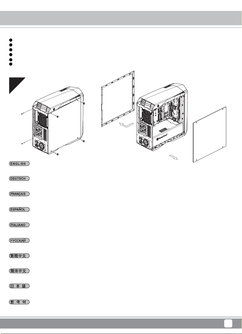
01
Loosen screws from both left and right side panels to remove them
Installation Guide
Lösen Schrauben an den linken und rechten Seitenwänden, nehmen Sie die Seitenwände ab
Desserrez les vis des deux panneaux latéraux pour les retirer
Desatornille tornillos de los paneles izquierdo y derecho para quitarlos
Per rimuovere i pannelli laterali allentare, per entrambi, le viti di serraggio
Отвинтите по винта, крепящих левую и правую боковых панели, и снимите панели
取下左右側板螺絲,卸下側板
取下左右侧板螺丝,卸下侧板
両方の左右パネルからネジを緩めて、取り外します
왼쪽과 오른쪽 사이드 패널에서 개씩 나사를 풀어 사이드 패널을 제거합니다
4
Page 8
Primera Series PM01-RGB / PM01-FX
Installation Guide
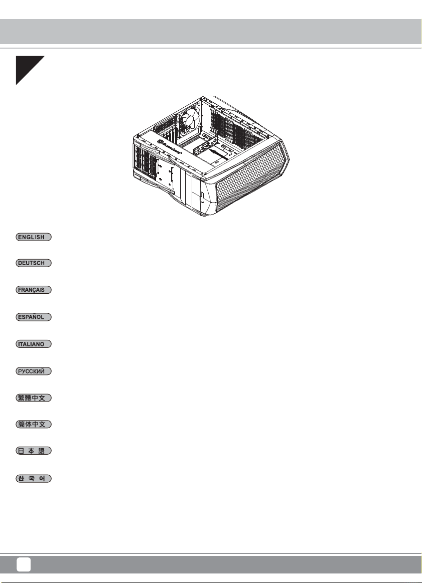
02
Insert the I/O shield included with your motherboard
Installieren Sie das hintere I/O-Blech im Gehäuse
Installez la plaque arrière de la carte mère dans le boîtier
Instale la placa trasera de E/S de la placa base en la carcasa
Installare la placca I/O della scheda madre nella sede preposta
Установите в корпус заднюю панель ввода-вывода материнской платы
將I/O彈片裝上機殼
将I/O弹片装上机箱
ケース内にマザーボード後部I/Oプレートをインストールします
메인보드 후방 I/O 판을 케이스에 장착합니다
5
Page 9
Primera Series PM01-RGB / PM01-FX
Installation Guide
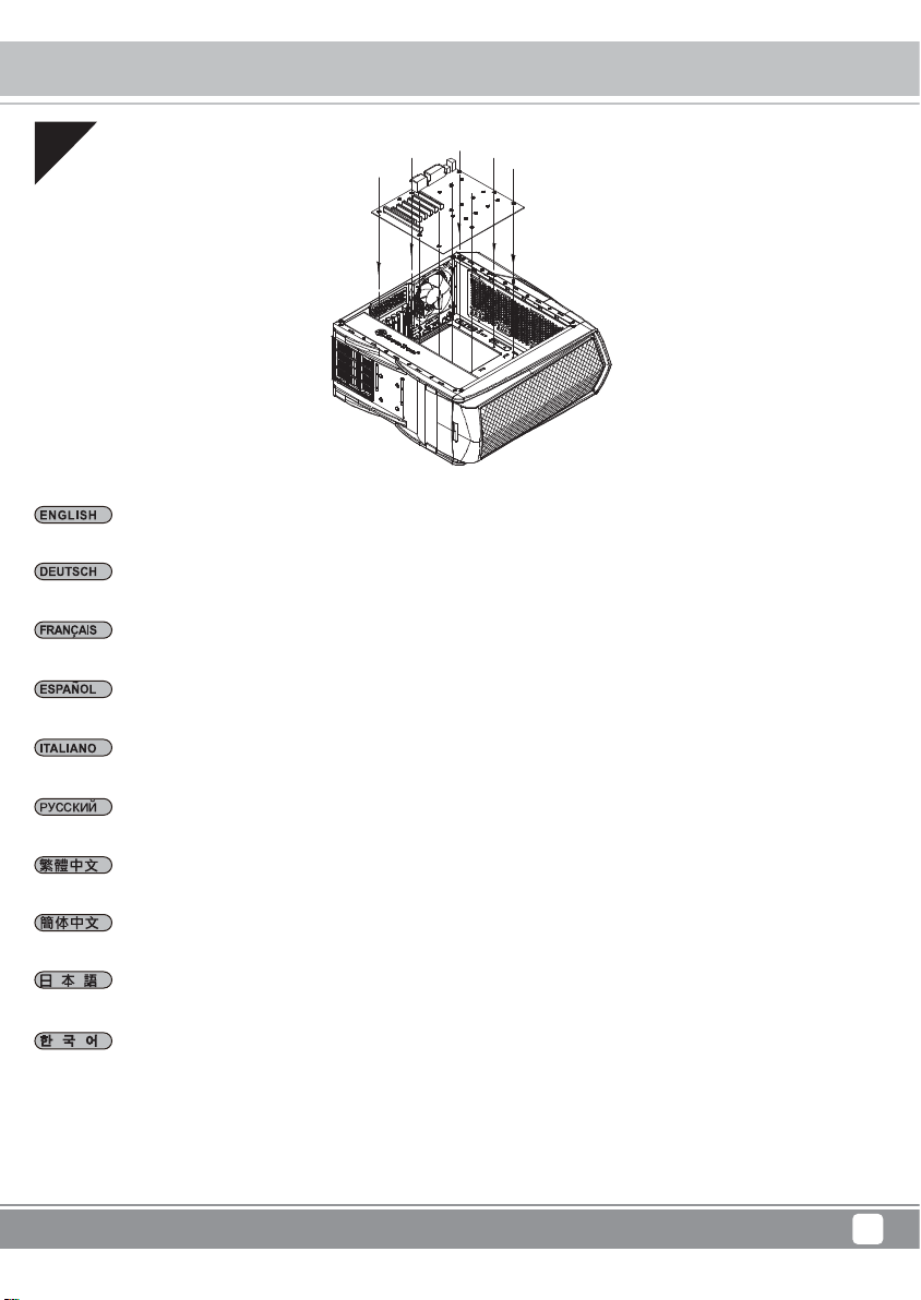
03
Insert standoffs as required by your motherboard in corresponding mounting holes, then install motherboard
Stecken Sie die Abstandshalter wie für Ihr Motherboard erforderlich in die entsprechenden Befestigungsbohrungen. Installieren Sie
dann das Motherboard
Insérez les entretoises comme requis par votre carte mère dans les trous de montage correspondant, puis installez la carte mère
Inserte los soportes según sea necesario para su placa base en los agujeros de montaje correspondientes, luego instale la placa base
Inserire nei corrispondenti fori di fissaggio i distanziatori, come richiesto dalla scheda madre, quindi installare la scheda madre
Принеобходимостиустановите опорныестойкидлясистемной платывсоответствующие крепежныеотверстия, затем
установитесистемнуюплату
請依需求安裝主機板螺柱,安裝主機板
请依需求安装主板螺柱,安装主板
マザーボードに応じて、必要な孔にスペーサーを取り付けてからマザーボードを取り付けます
메인보드에서 필요한 경우 해당 장착 구멍에 스탠드오프를 삽입한 후 메인보드를 설치합니다
6
Page 10
Primera Series PM01-RGB / PM01-FX
Installation Guide
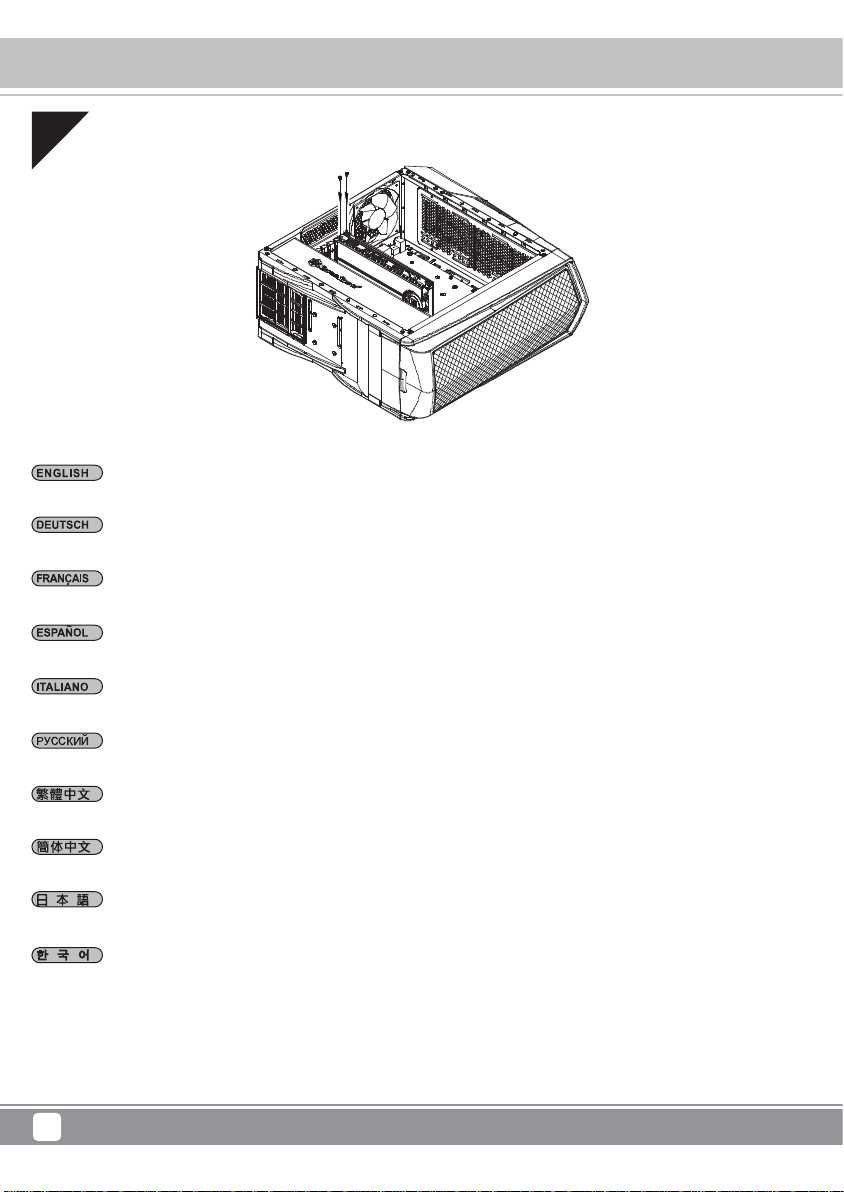
04
Remove expansion slot covers to install required expansion cards
Entfernen Sie Steckplatzabdeckungen, installieren Sie die gewünschten Erweiterungskarten
Retirez les équerres pour installer vos cartes d'extension
Quite las cubiertas de los zócalos de expansión para instalar las tarjetas de expansión necesarias
Rimuovere i cover degli slot di espansione per installare le schede
Снимите крышки слотов расширения для установки необходимых плат расширения
移除擴充槽檔片並安裝擴充卡
移除扩充槽档片并安装扩充卡
拡張スロットカバーを取り外して、必要な拡張カードを装着します
확장슬롯 커버를 제거한 후, 필요한 확장카드를 설치 합니다
7
Page 11
Primera Series PM01-RGB / PM01-FX
Installation Guide
05
Place your hard drive on the tray and secure with included screws. Caution: the secure with mount of hard drive tray should be place
at the same side with your hard drive connector jack
Positionieren Sie Ihre Festplatte am Einschub und sichern Sie sie mit den mitgelieferten Schrauben. Achtung: Die Befestigung des
Festplatteneinschubs sollte auf der Seite erfolgen, auf der sich auch der Festplattenanschluss befindet
Placez votre disque dur sur le plateau et fixez-le avec les vis fournies. Attention : le support du plateau de disque dur doit être du
même côté que la prise du connecteur de disque dur
Coloque su disco duro en la bandeja y fíjelo con los tornillos incluidos. Aviso: el disco duro montado en la bandeja debería situarse en
el mismo lado de su conector para disco duro
Collocare il disco rigido nel cassetto e fissarlo utilizzando le viti fornite in dotazione . Attenzione: la parte con le prese del cassetto
contenente il disco rigido deve essere collocata sullo stesso lato del connettore del disco rigido
Поместите жесткий диск в лоток и закрепите его винтами из комплекта . Внимание! Крепление лотка выполняется
с той же стороны, где расположен соединительный разъем для жесткого диска
請將您的硬碟安裝置硬碟托盤中,並以內附螺絲鎖固後,請注意鎖固硬碟托盤的方向必須與硬碟連接線接頭一致
请将您的硬盘安装置硬盘托盘中,并以内附螺丝锁固后,请注意锁固硬盘托盘的方向必须与硬盘连接线接头一致
ハードディスクをトレイに置き、付属のネジで固定します。注意:ハードディスクドライブトレイは、ハ ードディスクコネクタジャックと同じ
向きに設置してください
하드 드라이브를 트레이에 올려 놓고 제 공된 나사를 사용하여 고정합니 다. 주의: 하드 드라이브 트레이는 하드 드라이브 커넥터
잭과 동 일한 면에 놓고 장착해야 합니다
8
Page 12

Primera Series PM01-RGB / PM01-FX
Installation Guide
06
Install 2.5" drives behind the motherboard tray and secure with screws
Montieren Sie die 2,5" Laufwerke hinter der Motherboard-Aufnahme und sichern Sie sie mit Schrauben
Installez des disques de 2,5" derrière le plateau de la carte mère et attachez avec des vis
Instale los dispositivos de 2,5" tras la bandeja de la placa base y fíjelos con tornillos
Installare le unità 2,5" dietro il cassetto della scheda madre e fissarle con viti
За лотком системной платы установите 2,5-дюймовые приводы и закрепите их винтами
將2.5"硬碟裝上主機板背面,並鎖上螺絲
将2.5"硬盘装上主板背面,并锁上螺丝
マザーボードトレイ裏に2.5"ドライブを取り付け、ネジで固定します
메인보드 트래이 뒤에 2.5" 드라이브를 설치하고 나사로 고정합니다
9
Page 13

Primera Series PM01-RGB / PM01-FX
Installation Guide
07
We recommend that you start cable manage now and connect cables such as the ATX 24pin, front I/O connectors, and any other
connectors from front panel devices
Wir empfehlen, jetzt mit dem Verlegen der Kabel zu beginnen und die 24-poligen ATX-, Front-I/O- und sämtliche weiteren Kabel von
Geräten an der Frontblende anzuschließen
Nous vous recommandons de commencer à gérer l'organisation des câbles maintenant comment l'ATX 24pin, les connecteurs des
ports E/S de façade, et tout autre connecteur des appareils du panneau frontal
Le recomendamos que empiece a gestionar el enrutado de cables ahora y conecte cables como el ATX 24 pines, los conectores
frontales E/S y cualquier otro conector de los dispositivos del panel frontal
Vi raccomandiamo di iniziare subito la sistemazione delle connessioni e collegare quindi i connettori relativi ai cavi ATX 24pin, alle
connessioni I/O frontali e qualsiasi altro collegamento delle periferiche poste frontalmente
На этом этапе рекомендуется начать прокладку кабелей и подсоединить кабели, например кабель ATX с 24-контактным
разъемом, разъемы ввода-вывода передней панели и любые другие разъемы от устройств на передней панели
我們建議您可以在此時開始理線,請先安上ATX 24pin接線,Front panel controller 與Front I/O
我们建议您可以在此时开始理线,请先安上ATX 24pin接线,Front panel controller 与Front I/O
この時点でケーブル取り回しを考えながら、ATX24ピン、フロントI/Oコネクタ、その他フロントパネルデ バイスからのコネクタ類のケーブ
ルを 接続 するようお勧 めします
이 단계에서부터 ATX 24핀, 전면 I/O 커넥터, 그리고 전면 패널에서의 다른 커넥터 등 케이블 정리를 하시기를 권장합니다
10
Page 14

Primera Series PM01-RGB / PM01-FX
Installation Guide
08
Connect all cables and wires
Schließen Sie alle Kabel an
Branchez tous les câbles et les fils
Conecte todos los cables
Collegare tutti i cavi ed i fili
Подключите все кабели и провода
連接所有線材
连接所有线材
ケーブルとリード線を全て接続します
모든 케이블과 전선을 연결합니다
11
Page 15

Primera Series PM01-RGB / PM01-FX
Installation Guide
09
The default RGB LED controller can be controlled by the LED button on top of the case.Press and hold for four seconds to turn off.
Press again to resume state prior to turning off. Please connect controller’s 4pin peripheral power connector to the power supply
when installing system to power it
Die standardmäßige RGB-LED-Steuerung kann über die LED-Taste an der Oberseite des Gehäuses gesteuert werden. Halten Sie
sie zum Abschalten vier Sekunden lang gedrückt. Drücken Sie die Taste zum Wiederherstellen des Zustands vor der Abschaltung
noch einmal. Bitte verbinden Sie bei der Systeminstallation den 4-poligen Peripheriestromanschluss der Steuerung zur Stromversorgung
mit dem Netzteil
Le contrôleur LED RVB par défaut peut être contrôlé par le bouton LED en partie supérieure du boîtier. Appuyez et maintenez enfoncé
pendant quatre secondes pour éteindre. Appuyez à nouveau pour retrouver l'état d’avant l'arrêt. Veuillez brancher le connecteur
d'alimentation de périphérique à 4 broches du contrôleur à l'alimentation électrique lors de l'installation du système pour l'alimenter
El controlador LED RGB por defecto se puede controlar mediante el botón LED de la parte superior de la carcasa. Presione el botón
y manténgalo presionado durante cuatro segundos para apagarlo. Presione de nuevo para volver al estado anterior al apagado. Por
favor, enchufe el conector de potencia para periféricos de 4 pines del controlador a la fuente de alimentación cuando instale el sistema
para darle potencia
Il controller LED RGB predefinito può essere controllato dal tasto LED sulla parte superiore del case. Tenere premuto per quattro
secondi per spegnere. Premere di nuovo per ripristinare lo stato precedente allo spegnimento. Collegare il connettore di alimentazione
periferico a 4 pin del controller all'alimentazione durante l'installazione del sistema per alimentarlo
По умолчанию регулятором RGB LED можно управлять с помощью кнопки LED на верхней панели корпуса. Чтобы выключить,
нажмите и удерживайте в течении четырёх секунд. Нажмите ещё раз, чтобы возобновить состояние перед отключением.
Пожалуйста, подключите разъём питания 4pin регулятора к блоку питания при установке системы
出廠預設的RGB LED控制模式,是透過機殼上的LED按鍵進行切換,長按4秒可馬上關閉,輕按一下即恢復關閉前的選項。安裝時請將大
4pin接頭與電源供應器連接即可
出厂默认的RGB LED控制模式,是透过机箱上的LED按键进行切换,长按4秒可马上关闭,轻单击即恢复关闭前的选项。安装时请将大
4pin接头与电源供应器连接即可
デフォルトのRGBLEDコントローラはケース上部のLEDボタンでコントロールできます。4秒間押し続けるとオフになります。再度押すとオ
フ直前の状態に戻ります。本体取り付けの際は、コントローラの4ピン周辺電源コネクタを電源に接続してください
기본 RGB LED 컨트롤러는 케이스 상부의 LED 버튼으로 제어할 수 있습니다. 4초 동안 눌러 전원을 끕니다. 다시 한 번 눌러 끄기
전에 상태를 다시 시작합니다. 시스템을 설치할 때 컨트롤러의 4핀 병렬 전원 커넥터를 전원 공급장치에 연결하고 전원을 켭니다
12
Page 16

Primera Series PM01-RGB / PM01-FX
Installation Guide
10
LED SWITCH
MB
If you want to connect to device that has RGB 4pin signal output (+12V, G, R, B) such as motherborad built-in color control software,
then you only need to connect it using the included RGB 4pin cable.Please remove the default connected cable from two sides and
do not connect three cables simultaneously to avoid hardware failure
Wenn Sie eine Verbindung zu einem Gerät mit 4-poligem RGB-Signalausgang (+12 V, G, R, B), wie einer im Motherboard integrierten
Farbsteuerungssoftware, herstellen möchten, müssen Sie es nur über das mitgelieferte 4-polige RGB-Kabel anschließen. Bitte trennen
Sie das standardmäßig angeschlossene Kabel von zwei Seiten und schließen Sie zur Vermeidung von Hardwarefehlern keine drei
Kabel gleichzeitig an
Si vous souhaitez raccorder à un périphérique avec une sortie de signal RVB 4 broches (+12V, V, R, B) tel qu'un logiciel de contrôle
de couleur intégré de carte mère, vous devez utiliser uniquement le câble RVB 4 broches inclus. Veuillez retirer le câble connecté par
défaut des deux côtés et ne pas connecter trois câbles simultanément pour éviter une défaillance matérielle
IC
POWER IN
Si desea conectar el dispositivo que posee la señal de salida RGB de 4 pines (+12V, G, R, B) como el programa de control de color
incluido de la placa base, entonces sólo necesita conectarlo usando el cable RGB de 4 pines incluido. Por favor, retire el cable
conectado por defecto de los dos lados y no conecte tres cables de forma simultánea para evitar fallos de hardware.
Per collegarsi ad un dispositivo dotato di uscita del segnale RGB a 4 pin (+12 V, G, R, B), come il software di controllo del colore
integrato della scheda madre, basta utilizzare il cavo RGB a 4 pin in dotazione. Rimuovere il cavo collegato predefinito dai due lati e
non collegare tre cavi simultaneamente per evitare guasti hardware
Если вы хотите подключиться к устройству, которое имеет порт с выходным сигналом RGB 4pin (+12V, G, R, B), например,
к материнской плате, которая имеет возможность управления RGB подсветкой, то вам нужно всего лишь подключиться с
помощью прилагаемого кабеля RGB 4pin. Пожалуйста, отключите подключенный по умолчанию кабель с двух сторон и не
подключайте три кабеля одновременно, чтобы избежать сбоев в работе
若欲改用具有RGB 4pin訊號輸出的裝置 (+12V, G, R, B)來控制燈光,如主機板內建的控色軟體,請將RGB控制板兩端的線材拔除,
只連接中間的內附RGB 4pin訊號線,切勿同時連接三條線材使用,避免造成硬體故障
若欲改用具有RGB 4pin讯号输出的装置 (+12V, G, R, B)来控制灯光,如主板内建的控色软件,请将RGB控制板两端的线材拔除,只连
接中间的内附RGB 4pin讯号线,切勿同时连接三条线材使用,避免造成硬件故障
デバイスを、マザーボード内蔵カラー制御ソフトウェアのようなRGB4ピン信号出力(+12V,G,R,B)に接続することをお望みの場合は、付
属のRGB4ピンケーブルを使用して接続してください。両側からデフォルトの接続されたケーブルを外してください。また、ハードウェアの
故障を防ぐため、3本のケーブルを同時に接続しないようにしてください。
메인보드 내장 색 제어 소프트웨어와 같은 RGB 4핀 신호 출력 (+12V, G, R, B)이 있는 장치에 연결하려면, 함께 제공된 RGB 4핀
케이블을 사용하여 이를 연결하기만 하면 됩니다. 하드웨어 고장을 방지하려면 기본으로 연결되어있던 케이블을 양쪽에서 제거하고
3개의 케이블을 동시에 연결하지 마십시오
13
оборудования
Page 17

Primera Series PM01-RGB / PM01-FX
Installation Guide
11
IC
MB
As shown, please flip the RGB switch to the desired signal source.”MB” for motherboard control, “IC” for case button control. Be sure
to turn off power before switching signal input switch
Bitte stellen Sie den RGB-Schalter wie angezeigt auf die gewünschte Signalquelle ein. „MB“ für Motherboard-Steuerung, „IC“ für
Gehäusetastensteuerung. Achten Sie darauf, die Stromversorgung vor Umschalten des Signaleingangsschalters abzuschalten
Comme indiqué, veuillez basculer le commutateur RVB sur la source de signal souhaitée. « MB » pour commande de la carte mère, « IC »
pour commande du bouton du boîtier. Assurez-vous de mettre hors tension avant de basculer le commutateur d'entrée de signal
Según se muestra, por favor gire el interruptor RGB a la fuente de señal deseada. “MB” es para controlar la placa base, “IC” para controlar
el botón de la carcasa. Asegúrese de quitar la potencia antes de activar el interruptor de entrada de señal
Come mostrato, portare l'interruttore RGB sulla sorgente del segnale desiderata. "MB" per il controllo della scheda madre, "IC" per
il controllo tasto del case. Assicurarsi di spegnere l'alimentazione prima di commutare l'interruttore di ingresso del segnale
Пожалуйста, переведите переключатель RGB на нужный источник сигнала, как показано. ”MB” - для управления с материнской
платы, “IC” - для управления с помощью кнопки на корпусе. Обязательно выключите питание перед переключением выходного
сигнала
如圖標示,請將RGB控制板切換開關方向與訊源,使用主機板控制時切至MB;使用機殼按鈕時切至IC,請務必於斷電時依需求作切換
如图标示,请将RGB控制板切换开关方向与讯源,使用主板控制时切至MB;使用机箱按钮时切至IC,请务必于断电时依需求作切换
図のようにRGBスイッチを必要な信号ソースに合わせて切り替えます。マザーボード制御には「MB」、ケースボタン制御には「IC」を選択し
ます。信号入力スイッチを切り替える前に、必ず電源をオフにしてください
그림과 같이 RGB 스위치를 원하는 신호 소스로 전환하십시오. "MB"는 메인보드 컨트롤을 의미하고, "IC"는 케이스 버튼 컨트롤을
의미합니다. 신호 입력 스위치를 전환하기 전에 전원을 끄십시오
14
Page 18

Primera Series PM01-RGB / PM01-FX
Installation Guide
12
Install power supply into the case
Bauen Sie das Netzteil ins Gehäuse ein
Installez la source d’alimentation dans le châssis
Instale la fuente de alimentación en la carcasa
Installazione dell’alimentatore nel case
Установите в корпус блок питания
安裝電源
安装电源
電源をケースに取り付けます
전원 공급장치를 케이스에 설치합니다
15
Page 19

13
Reinstall side panels back onto the case
Bringen Sie die Seitenteile wieder an
Primera Series PM01-RGB / PM01-FX
Installation Guide
Réinstallez les panneaux latéraux sur le chassis
Reinstale los paneles laterales de nuevo en la carcasa
Reinstallare sul case i pannelli laterali
Установите на место боковые панели корпуса
裝回左右側板
装回左右侧板
ケースに側面パネルをもどします
측면 패널을 케이스에 도로 설치합니다
16
Page 20

Primera Series PM01-RGB / PM01-FX
Top Cover Removal Guide
Loosen side screws then push up to remove the top cover
Lösen Sie die seitlichen Schrauben; entfernen Sie dann die obere Abdeckung, indem Sie sie nach oben drücken
Desserrer les vis latérales puis poussez pour retirer le couvercle supérieur
Afloje los tornillos laterales y luego empuje hacia arriba para retirar la cubierta superior
Allentare le viti laterali, quindi spingere verso l'alto per rimuovere la copertura superiore
Открутите боковые винты, затем потяните вверх чтобы снять верхнюю крышку
移除側邊螺絲後,往上輕輕施力即可拔起上蓋
移除侧边螺丝后,往上轻轻施力即可拔起上盖
側面のネジを緩めてから上に押して上面カバーを外します
측면 나사를 플고 상부 커버를 밀어 올려 제거합니다
17
Page 21

Primera Series PM01-RGB / PM01-FX
Connector Definition
(1) Fort panel connector installation
Power switch installation guide:
Please refer to the motherboard manuals for the motherboard’s “Front Panel Connector” or “System Panel Connector” pin definition.
Power switch have no polarity, so they can be connected in any orientation
Ein-/Ausschalter und installieren:
Bitte suchen Sie in der Motherboard-Dokumentation nach der Pinbelegung der Anschlüsse des Frontbedienfeldes („Front Panel
Connectors“ oder „System Panel Connectors“). Ein-/Austaste und benötigen keine bestimmte Polarität, können daher beliebig
(ohne auf + und - zu achten) angeschlossen werden
Guide d'installation des interrupteurs d'allumage:
Veuillez-vous référer au manuel de votre carte mère pour la description des broches "des connecteurs du panneau frontal" et des
broches "des connecteurs du panneau système". Les interrupteurs d'allumage ne possède pas de polarité, donc ils peuvent être
branché dans les deux sens
Guía de instalación de los interruptores:
Por favor, consulte en los manuales de la placa base la configuración de pines del “Conector de panel frontal” ó “Conector de panel
de sistema” de su placa base. Los interruptores no tienen polaridad, luego se pueden conectar con cualquier orientación
Guida all’installazione dei connettori Power Switch:
Fare riferimento al manuale della scheda madre nella sezione “Connettori del pannello frontale” o “Connettori del pannello di sistema”.
Power switch non hanno polarità, posso essere pertanto connessi con qualsiasi orientamento
Инструкция по подключению выключателя питания и кнопки:
Описание контактов разъемов приведены в разделах “Разъемы передней панели” или “Разъемы системной панели”
руководства пользователя материнской платы. Выключатель питания и кнопка не имеют полярности, поэтому их можно
подключать в любой ориентации
Power Switch安裝說明:
請參考主機說明書的Front Panel Connectors安裝Pin Define,將Connector插上;Power Switch並無正負極性之分, 反插正插都不影
響功能性
Power Switch安装说明:
请参考主机说明书的Front Panel Connectors 安装Pin Define,将Connector插上;Power Switch并无正负极性之分, 反插正插都不影
响功能性
電源スイッチおよのインストールガイド:
マザーボードの「フロントパネルコネクタ」または「システムパネルコネクタ」のピン配列についてはマザーボードマニュアルを参照してく
ださい。電源スイッチとに極性はないので、いずれの方向でも接続できま
파워 스위치 스위치 설치 가이드 메인보드 매뉴얼의 전면패널 커넥터 혹은 시스템패널 커넥터 핀을 참조하기 바랍니다. 파워 스위치와
스위치는 극성이 없어 어떤 방향으로 설치해도 무방합니다
18
Page 22

Primera Series PM01-RGB / PM01-FX
Connector Definition
(2) LED Connector Installation Guide
Please refer to the motherboard manuals for the motherboard’s “Front Panel Connector” or “System Panel Connector” pin definition.
White colored wires are negative while other colored wires are positive. Power LED connector is made to be individual pins by design
to accommodate different motherboard specifications
Bitte suchen Sie in der Motherboard-Dokumentation nach der Pinbelegung der Anschlüsse des Frontbedienfeldes („Front Panel Connectors“
oder „ System Panel Connectors“). Die weißen/ schwarz Adern sind negativ (-), die farbigen Adern positiv (+).Die Kabel für die
Betriebsanzeige-LED sind zur Kompatibilität mit unterschiedlichsten Motherboards einzeln, nicht als kompletter Stecker ausgeführt. Achten
Sie hier bitte auf die richtige Polarität, lesen Sie in der Dokumentation Ihres Motherboards nach
Veuillez-vous référer au manuel de votre carte mère pour la description des broches "des connecteurs du panneau frontal" et des
broches "des connecteurs du panneau système". Les câbles colorés en blanc/noir sont négatifs alors que ceux d'une autre couleur
sont positifs. Les câbles de la LED Power sont séparés afin d'être compatible avec différentes cartes mères, donc vérifiez bien
qu'ils sont branchés avec la bonne polarité en vous référant au manuel de votre carte mere
Por favor, consulte en los manuales de la placa base la configuración de pines del “Conector de panel frontal” ó “Conector de panel de
sistema” de su placa base. Los cables de color blanco/negro son negativos mientras que los de color son positivos. Los cables LED de
potencia tienen pines separados para compatibilidad con diferentes definiciones de pines de la placa base luego por favor, asegúrese
de que están conectados en la polaridad correcta consultando el manual de su placa base
Fare riferimento al manuale della scheda madre nella sezione “Connettori del pannello frontale” o “Connettori del pannello di sistema”.
I cavi di colore bianco/nero sono il polo negativo, mentre quelli di colore diverso il positivo
Описание контактов разъемов приведены в разделах “Разъемы передней панели” или “Разъемы системной панели” руководства
пользователя материнской платы. Белые/черный провода - отрицательной полярности, цветные провода - положительной
полярности. Провода светодиодного индикатора питания имеют отдельные контакты для совместимости с различными типами
контактов материнских плат, поэтому обратитесь к руководству пользователя материнской платы и убедитесь, что
соблюдена
請參考主機說明書的Front Panel Connectors安裝Pin Define,將Connector插上;白/黑色線的部分為負極,彩色線的部分是正極。
Power LED為了適 應各主機板的不同, 特別設計為散Pin樣式,請安心使用
请参考说明书的Front Panel Connectors安装Pin Define,将Connector插上;白/黑色线的部份为负极,彩色线的部份为正极。
Power LED为了适应主机 板的不同, 特别设计为散Pin样式,请安心使用
マザーボードの「フロントパネルコネクタ」または「システムパネルコネクタ」ピン配列についてはマザーボードマニュアル参照してくださ
い。白/黑色のリード線はマイナスで、色の着いたリード線がプラスです。電源LEDリード線は種々のマザーボードピン定義と互換性を持た
せるため分離されたピンとなっているので、ご使用のマザーボードマニュアルを参照して、適切な極性に接続されるようお確かめください
메인보드 매뉴얼의 전면패널 커넥터 혹은 시스템패널 커넥터 핀을 참조하기 바랍니다. 하얀/검은선의 경우 음극이며, 다른 색의 경우
양극입니다. 파워 LED 선은 분리되어 다양한 메인보드에서 동작할 수 있도록 되어 있습니다. 그러므로 메인보드 매뉴얼을 참조하여
올바를 극성을 주의해 선택하시기 바랍니다
полярность
19
Page 23

Primera Series PM01-RGB / PM01-FX
Connector Definition
(3) Front I/O Connecter Guide
Below are the front I/O connectors pin definition, please also check your motherboard manual to cross reference with motherboard’s front I/O pin
headers. SilverStone’s I/O connectors are in block type to simplify installation
Nachstehend finden Sie die Pinbelegung der vorderen E/A-Anschlüsse; bitte gleichen Sie zudem das Handbuch Ihres Motherboards
mit den vorderen E/A-Pinzuweisungen ab. SilverStones E/A-Anschlüsse befinden sich zur Vereinfachung der Installation in Blockart
Au dessous de la description des broches des ports d'E/S, veuillez aussi vérifier sur le manuel de votre carte mère de manière croisée que les
broches sont correctement placées. Les connecteurs d'E/S de SilverStone sont en bloc pour en simplifier leur installation
A continuación se detallan los pines para conectores E/S frontales, compruebe también por favor el manual de su placa base para cotejar los pines
E/S frontales de la misma. Los conectores E/S de SilverStone son del tipo bloque para simplificar la instalación
Di seguito lo schema delle connessioni I/O frontali, confrontare lo schema con quanto riportato sul manuale della scheda madre per effettuare un
controllo incrociato. I connettori I/O Silverstone, per semplificare l’installazione, sono del tipo “a blocco”
Ниже приведено описание контактов передних разъемов ввода/вывода. Обратитесь также к руководству пользователя материнской платы
за описанием передних разъемов ввода/вывода типа "пин-хедер". Разъемы ввода/вывода "SilverStone" - блочного типа, что облегчает сборку
下表為Front I/O Connectors的Pin Define,請參閱主機板說明書的各Front I/O Connectors Pin Define一一核對。
PM01-RGB的Front I/O Connectors完全採用集合Pin方式以簡化安裝
下表为Front I/O Connectors的Pin Define,请参阅主机板说明书的各Front I/O Connectors Pin Define一一核对。
PM01-RGB的Front I/O Connectors完全采用集合Pin方式以简化安装
以下はフロントI/Oコネクタピン配列ですが、お持ちのマザーボードのフロントI/Oピンヘッダは、マザーボードマニュアルをご参照ください。シルバース
トーンの I/ Oコネクタは、インストールの容易なブロックタイプになっています
아래는 전면 I/O 커넥터의 핀 사양입니다. 메인보드 매뉴얼을 참조해, 메인보드의 전면 I/O 핀사양을 재 확인한 후 설치합니다. SilverStone의 I/O
커넥터는 블록 타입으로 구성되어 있어 간편한 설치가 가능합니다
USB 3.0 CONNECTOR HD CONNECTOR
Pin 1
Vbus
IntA_P1_SSRX-
IntA_P1_SSRX+
GND
IntA_P1_SSTX-
IntA_P1_SSTX+
GND
IntA_P1_D-
IntA_P1_D+
ID
Pin 19
Vbus
IntA_P2_SSRXIntA_P2_SSRX+
GND
IntA_P2_SSTXIntA_P2_SSTX+
GND
IntA_P2_DIntA_P2_D+
Pin 11Pin 10
20
Page 24

Primera Series PM01-RGB / PM01-FX
Connector Definition
(4) RGB LED Signal Cable Connecter Guide
Please confirm the connector and pin header’s definition & direction when connecting cables
Bitte prüfen Sie beim Anschließen der Kabel Pinbelegung und Ausrichtung von Anschluss und Stiftleiste
Vérifiez soigneusement les branchements réalisés au niveau des connecteurs à chaque étape de l’assemblage
Por favor, confirme la dirección y orientación del conector y pines cuando conecte los cables
Verificare la definizione e la direzione dei connettori durante il collegamento dei cavi
Пожалуйста, проверяйте направление разъёмов и коннекторов при подключении кабелей
連接線材時務必確認接頭與pin port定義與方向相同
连接线材时务必确认接头与pin port定义与方向相同
ケーブル接続時には、コネクタおよびピンヘッダの配列および方向を確認してください
케이블 연결 시 커넥터와 핀 헤더의 정의 및 방향을 확인하십시오
21
Page 25

Primera Series PM01-RGB / PM01-FX
Connector Definition
(5) PWM Fan Hub PCB Guide
1. Only header on white colored socket supports speed detection
1. Nur die Stiftleiste am weißen Sockel unterstützt Geschwindigkeitserkennung
1. Seule l'embase sur le socket de couleur blanche prend en charge la détection de vitesse
1. Sólo el cabezal con el zócalo de color blanco acepta la detección de velocidad
1. Solo il connettore sulla presa bianca supporta il rilevamento di velocità
1. Только разъём с белым цветом поддерживает управление скорости
1. 僅白色風扇插座支援轉速偵測功能
1. 仅白色风扇插座支持转速侦测功能
1.速度検知に対応するのは、白色のソケット上のヘッダのみです
1. 흰색 소켓의 헤더만 속도 측정을 지원합니다
22
Page 26

Primera Series PM01-RGB / PM01-FX
Connector Definition
2. Fan will not start unless SATA power cable is connected. Speed detection and PWM speed control are functional only when motherboard is
connected
2. Der Lüfter startet nicht, sofern das SATA-Netzkabel nicht angeschlossen ist. Geschwindigkeitserkennung und PWM-Geschwindigkeitssteuerung
funktionieren nur, wenn das Motherboard verbunden ist
2. Le ventilateur ne démarre pas jusqu'à ce que le cordon d'alimentation SATA soit branché. La détection de la vitesse et le contrôle de la vitesse PWM
ne marchent que lorsque la carte mère est connectée
2. El ventilador no arrancará a menos que el cable de potencia SATA esté conectado. Las funciones de detección de velocidad y control de velocidad
PWM son funcionales solo cuando la placa base está conectada
2. Le ventole non si avviano finché non si collega il cavo di alimentazione SATA. Il rilevamento della velocità e il controllo della velocità PWM sono
operativi solo quando si collega la scheda madre
2. Вентилятор не запустится, пока не будет подключен кабель питания SATA. Определение скорости вращения и ее контроль по шине ШИМ
доступны только при подключении системной платы
2. SATA電源線接上後,風扇才會開始運轉;連接主機板後才能支援PWM控速與轉速偵測
2. SATA电源线接上后,风扇才会开始运转;连接主板后才能支持PWM控速与转速侦测
2.SATA電源ケーブルを接続しないとファンは回転しません。速度検出およびPWM速度制御は、マザーボードに接続されている場合にのみ機能します
2. SATA 전원 케이블이 연결되어 있지 않으면 팬이 시작되지 않습니다. 속도 감지 및 PWM 속도 제어는 메인보드가 연결되어 있을 때만 작동합니다
3. Speed control function is unavailable for 3pin fans
3. Geschwindigkeitssteuerung ist bei 3-poligen Lüftern nicht verfügbar
3. La fonction de contrôle de la vitesse n'est pas disponible avec les ventilateurs à 3-broches
3. La función de control de velocidad no está disponible para los ventiladores de 3 pines
3. La funzione di controllo velocità non è disponibile per ventole a 3 pin
3. Функция контроля скорости недоступна для вентиляторов с 3-контактным подключением
3. 連接3pin風扇接線時,無控速功能
3. 连接3pin风扇接线时,无控速功能
3.速度制御機能は3ピンファンでは機能しません
3. 3핀 팬의 경우, 속도 제어 기능을 사용할 수 없습니다
23
Page 27

Primera Series PM01-RGB / PM01-FX
Component size limitations
The PM01-RGB was designed to accommodate oversized components, but we still recommend
referring to the following dimension guidelines:
(1) CPU Cooler limitation
180MM
9MM
33MM
Height limitation for CPU cooler is 180mm with 33mm clearance over the motherboard’s top edge
Höhenbeschränkung für CPU-Kühler 180 mm mit einem Freiraum von 33 mm oberhalb der Motherboard-Oberkante
La limitation de hauteur des refroidisseurs de processeurs est 180mm avec un espace de 33mm au-dessus du bord supérieur de la
carte mere
La limitación de altura para disipadores de CPU es de 180mm con un espacio libre de 33mm sobre el borde superior de la placa base
La limitazione dell’altezza del dissipatore di calore CPU è di 180 millimetri con uno spazio libero di 33 mm sopra il bordo superiore
della scheda madre
Ограничение по высоте для системы охлаждения процессора составляет 180 мм с 33-мм зазором над верхним краем
системной платы
Cooler限高是180mm,Cooler外源允許超出主機板上邊界33mm
Cooler限高是180mm,Cooler外源允许超出主板上边界33mm
CPUクーラーの高さ限度は、マザーボード上側の余裕33mmを取って、180mmです
CPU 쿨러의 높이 제한은 180mm로서 메인보드 상단 가장자리 위로의 허용 오차가 33mm입니다
24
Page 28

Primera Series PM01-RGB / PM01-FX
Component size limitations
(2) Power supply limitation
The PM01-RGB supports power supply with depth of up to 240mm
Das PM01-RGB unterstützt Netzteile mit einer Tiefe von bis zu 240 mm
Le PM01-RGB est compatible avec les alimentations d'une profondeur inférieure ou égale à 240mm
La PM01-RGB acepta fuentes de alimentación con una profundidad de hasta 240mm
PM01-RGB supporta alimentatori con profondità fino a 240mm
Корпус PM01-RGB допускает установку блока питания глубиной до 240 мм
PM01-RGB的PSU可用總空間有240mm
PM01-RGB的PSU可用总空间有240mm
PM01-RGBは最高240mmの奥行きの電源をサポートします
PM01-RGB은 240mm의 깊이를 갖는 파워 서플라이까지 지원합니다
22.6MM
25
240MM
Page 29

Primera Series PM01-RGB / PM01-FX
Component size limitations
(3) Graphics card / expansion card length limitation
425MM
175MM
PM01-RGB can support 16.7" (425mm) long cards, which covers all retail consumer graphics cards available on the market
PM01-RGB unterstützt Karten bis 16,7" (425 mm). Dies deckt alle auf dem Markt verfügbare Consumer-Grafikkarten ab
PM01-RGB peut supporter des cartes de jusqu'à 16,7" (425mm) de long, ce qui couvre toutes les cartes graphiques disponibles
actuellement sur le marché
La PM01-RGB puede aceptar tarjetas largas de 16,7" (425mm), lo que cubre todas las tarjetas gráficas para usuario disponibles en
el mercado
PM01-RGB supporta schede lunghe da 16,7" (425mm), coprendo tutte le schede grafiche consumer in vendita al dettaglio disponibili
sul mercato
Корпус PM01-RGB позволяет устанавливать16,7" (425 мм) карты, что покрывает весь доступный рынок розничной продажи
графических карт
PM01-RGB支援 16.7" (425mm) 顯示卡市面上零售的消費及顯示卡應該都能安裝
PM01-RGB支持16.7" (425mm) 显示卡市面上零售的消费及显示卡应该都能安装
PM01-RGBは16.7"(425mm)長のカードに対応します。これは市場に出回るリテール消費用グラフィックスカード全てを網羅します
PM01-RGB는16.7" (425mm) 의 긴 카드를 지원할 수 있으며, 이는 시중에 출시된 모든 소매 소비자용 그래픽 카드를 포함합니다
26
Page 30

Primera Series PM01-RGB / PM01-FX
Component size limitations
(4) Liquid cooling radiator limitations
120MM, 140MM
240MM, 280MM
360MM
120MM, 140MM
140MM
360mm Radiator limitation
120MM
35.55MM
72.9MM
33MM
71.4MM
240MM, 280MM
360MM
45MM
6.6MM
27
Page 31

Primera Series PM01-RGB / PM01-FX
Upgrade And Mainterance
Illustration: An example of a GPU cooler that is filled with dust and has lost most of its cooling performance PM01-RGB’s positive air pressure design
is an effective configuration that will reduce dust buildup inside the case. Small air particles or lint will accumulate over time on intake filters instead
of on the components inside the case. To maintain PM01-RGB’s excellent cooling performance for years to come, we recommend to clean all fan
filters regularly every three months or half a year (depending on your environment)
Das vorteilhafte Luftdruckdesign des PM01-RGB ist eine effektive Konfiguration, die Staubablagerungen innerhalb des Gehäuses vermindert. Im Laufe
der Zeit sammeln sich kleine Partikel und Fusseln an den Luftzufuhrfiltern, anstatt an den Komponenten im Gehäuseinneren, an. Sie können eine
jahrelange optimale Kühlleistung des PM01-RGB gewährleisten, indem Sie alle Lüfterfilter regelmäßig alle drei bis sechs Monate reinigen (je nach
Umgebungsbedingungen)
La conception à pression d'air positive du PM01-RGB est une configuration efficace permettant de réduire l'accumulation de la poussière dans le
boîtier. De petites particules d'air ou de peluche vont s'accumuler avec le temps sur les filtres d'aspiration, et non sur les composants à l'intérieur
du boîtier. Pour conserver les excellentes performances de refroidissement du PM01-RGB au fil des ans, nous vous recommandons de nettoyer
l'ensemble des filtres des ventilateurs, tous les trois ou six mois (selon votre environnement)
El diseño de presión de aire positiva de la PM01-RGB es una configuración efectiva que reducirá la acumulación de polvo dentro de la carcasa.
Pequeñas partículas de polvo ó pelusa se irán acumularán con el transcurso del tiempo en los filtros de entrada en lugar de en los componentes
del interior de la carcasa. Para mantener la excelente capacidad de refrigeración de la PM01-RGB en años venideros, le recomendamos que limpie
con regularidad todos los filtros de los ventiladores cada tres meses ó seis meses (dependiendo de dónde viva)
Il design a pressione positiva di PM01-RGB riduce considerevolmente gli accumuli di polvere all’interno del case. Le piccole particelle si accumulano
infatti sui filtri invece che sui componenti interni. Per mantenere le eccellenti prestazioni di raffreddamento di PM01-RGB negli anni a venire vi
raccomandiamo di procedere ad una regolare pulizia dei filtri (con cadenza trimestrale o semestrale dipendentemente dall’ambiente un cui è
disposto il sistema)
Конструкция корпуса PM01-RGB обеспечивает избыточное давление воздуха и, таким образом, имеет эффективную конфигурацию,
препятствующую скоплению пыли внутри корпуса. Небольшие частицы и волокна, содержащиеся в воздухе, со временем будут скапливаться
на впускных фильтрах, а не на компонентах, находящихся внутри корпуса. Для поддержания превосходного охлаждения компонентов в
корпусе PM01-RGB в течение многих лет рекомендуется регулярно
(в зависимости от условий окружающей среды)
圖:被灰塵卡死的顯示卡散熱器 PM01-RGB的正壓差搭配濾網方式是經的起時間考驗最有效的防塵方式。在使用相當長一段時間後,棉屑灰塵或其他可
能妨礙散熱效能的小異物只會卡在濾網,而不是電腦內的元件上面。我們重視的散熱效能,是在您使用電腦長達2~3年後還能維持與全新的無異。為了
維持這種散熱效能您只需要定期清理濾網,而不是電腦裡面的元件。 視環境而定,我們建議您每6個月~1年必須清理濾網
图:被灰尘卡死的显示卡散热器 PM01-RGB的正压差搭配滤网方式是经的起时间考验最有效的防尘方式。在使用相当长一段时间后,棉屑灰尘或其他可
能妨碍散热效能的小异物只会卡在滤网,而不是计算机内的组件上面。我们重视的散热效能,是在您使用计算机长达2~3年后还能维持与全新的无异。
为了维持这种散热效能您只需要定期清理滤网,而不是计算机里面的组件。 视环境而定,我们建议您每6个月~1年必须清理滤网
PM01-RGBの正圧設計は、ケース内のホコリの蓄積を減少させる有効な構造です。時と共に空気中の微粒子または糸くずはケース内のコンポーネト上の
代わりに 取 入れ口 フィルタに溜まります。この先何年もの間PM01-RGBの素晴らしい冷却性能を維持するには、全てのファンを6ヶ月ないしは1年(環境に
依存)ごとに規則的に清掃するようお勧めしま。
PM01-RGB의 양압 디자인은 케이스 내부에 먼지가 싸이는 것을 방지 하기 위한 효과적인 디자인입니다. 작은 분진이나 먼지는 케이스 내부에
있는필터에 시간에 따라 쌓이게 됩니다. PM01-RGB의 우수한 냉각 성능을 계속 유지하기 위헤서 매 3개월 혹은 6개월(사용환경에 따라)마다 필터
청소를권장합니다
очищать все фильтры вентиляторов: раз в 3 месяца или раз в полгода
28
Page 32

Primera Series PM01-RGB / PM01-FX
Fan removal guide
Remove main filter, Unscrew screws holding the fans to remove them
Entnehmen Sie den Hauptfilter, Lösen Sie die Befestigungsschrauben des Lüfters, nehmen Sie sie heraus
Enlevez le filtre principal, Dévissez les vis des ventilateurs pour les enlever
Retire filtro principal, Suelte los tornillos que soportan los ventiladores para retirarlos
Rimuovere il filtro principale, Svitare le viti che fissano le ventole per rimuoverle
Снимите главный фильтр, Чтобы извлечь вентиляторы, отверните винты их крепления
移除主濾網,卸除固定風扇的螺絲,卸除風扇
移除主滤网,卸除固定风扇的螺丝,卸除风扇
メインフィルターを取り外します,ファン を固定しているネジを外して、取り外します
주 필터를 분리합니다,팬을 고정하는 나사를 풀어 팬을 분리합니다
29
Page 33

Primera Series PM01-RGB / PM01-FX
Fan filter purchase process
If you accidentally loose/damage filters or need additional ones for backup, please contact your local SilverStone retailers or distributors
for purchasing information:
http://www.silverstonetek.com/wheretobuy_all.php
Wenn Sie einen Lüfterfilter als Zusatz, zum Austausch bei Verlust oder Beschädigung oder einfach als Reserve erwerben möchten, suchen Sie
einfach auf unseren Internetseiten nach einem Händler oder Distributor in Ihrer Nähe:
http://www.silverstonetek.com/wheretobuy_all.php
Pour acheter un filtre du ventilateur au détail comme pour l’améliorer ou pour le remplacer en caisson de perte, de dommage ou simplement en
rechange, vous pouvez rechercher sur notre site Internet pour connaître les revendeurs ou les distributeurs les plus proches de chez vous:
http://www.silverstonetek.com/wheretobuy_all.php
Para comprar un filtro para ventilador como mejora o reemplazo en caso de pérdida, daño o simplemente como recambio, puede buscar en nuestra
página web para encontrar el distribuidor o vendedor autorizado más cercano:
http://www.silverstonetek.com/wheretobuy_all.php
Per acquistare un filtro della ventola al dettaglio per la sostituzione in caso di perdita, danni o semplicemente uno di riserva, è possibile cercare sul
nostro sito web i rivenditori o distributori più vicini:
http://www.silverstonetek.com/wheretobuy_all.php
На нашем сайте Вы найдете ближайшего торгового посредника или дистрибьютора, у которого можно приобрести фильтр вентилятора
для замены в случае потери или повреждения старого фильтра, или про запас.
http://www.silverstonetek.com/wheretobuy_all.php
添購濾網如果您不慎遺失、人為損壞或只是想要多購買濾網備用。請與我們的經銷點聯絡進行購買。請上SilverStone網站查詢各區域經銷:
http://www.silverstonetek.com.tw/wheretobuy_all.php?area=tw
添购滤网如果您不慎遗失、人为损坏或只是想要多购买滤网备用。请与我们的经销点联络进行购买。请上SilverStone网站查询各区域经销:
http://www.silverstonetek.com.tw/wheretobuy_all.php?area=tw
アップグレードまたは損失の場合の交換用、または単にバックアップとして小売ファン・フィルタ を 購 入 する に は 、最寄りの小売業者または卸売業者を下
記の当社ウェブサイトから検索できます:
http://www.silverstonetek.com/wheretobuyall.php
팬 필터가 분실 또는 손상되어 소매로 팬 필터를 구입하거나 단순히 여분으로 구입하려는 경우, 당사의 웹사이트에서 가까운 판매점을 검색할 수
있습니다.
http://www.silverstonetek.com/wheretobuy_all.php
30
Page 34

计算器机箱 有毒有害物质/元素及其化学含量表
部件名称
机壳(金属)
机壳(塑胶)
风扇
电子卡
线材
螺丝
包材
○:表示该有毒有害物质在该部件所有均质材料中的含量均在SJ/T11364-2014
标准规定的限量要求以下。
×:表示该有毒有害物质在该部件材料中的含量超出SJ/T11364-2014标准规定
的限量要求。
本表中有×的部件均符合欧盟RoHS法规,即欧盟第2011/65/EU号指令要求。
This product has a limited 1 year warranty in North America and Australia.
For information on warranty periods in other regions, please contact your reseller or SilverStone
authorized distributor.
铅
(Pb)
×
○
×
×
×
×
○
汞
(Hg)
○
○
○
○
○
○
○
镉
(Cd)
○
○
○
○
○
○
○
六价铬
(Cr(VI))
○
○
○
○
○
○
○
多溴联苯
(PBB)
○
○
○
○
○
○
○
产品合格证
检验员:检01
生产日期:见产品条码
多溴二苯醚
(PBDE)
○
○
○
○
○
○
○
Warranty terms & conditions
1. Product component defects or damages resulted from defective production is covered under warranty.
Defects or damages with the following conditions will be fixed or replaced under SilverStone Technology’s jurisdiction.
a) Usage in accordance with instructions provided in this manual, with no misuse, overuse, or other inappropriate actions.
b) Damage not caused by natural disaster (thunder, fire, earthquake, flood, salt, wind, insect, animals, etc…)
c) Product is not disassembled, modified, or fixed. Components not disassembled or replaced.
d) Warranty mark/stickers are not removed or broken.
Loss or damages resulted from conditions other than ones listed above are not covered under warranty.
2. Under warranty, SilverStone Technology’s maximum liability is limited to the current market value for the product (depreciated value, excluding
shipping, handling, and other fees). SilverStone Technology is not responsible for other damages or loss associated with the use of product.
3. Under warranty, SilverStone Technology is obligated to repair or replace its defective products. Under no circumstances will SilverStone
Technology be liable for damages in connection with the sale, purchase, or use including but not limited to loss of data, loss of business, loss of
profits, loss of use of the product or incidental or consequential damage whether or not foreseeable and whether or not based on breach of warranty,
contract or negligence, even if SilverStone Technology has been advised of the possibility of such damages.
4. Warranty covers only the original purchaser through authorized SilverStone distributors and resellers and is not transferable to a second hand
purchaser.
5. You must provide sales receipt or invoice with clear indication of purchase date to determine warranty eligibility.
6. If a problem develops during the warranty period, please contact your retailer/reseller/SilverStone authorized distributors or SilverStone
http://www.silverstonetek.com.
Please note that: (i) You must provide proof of original purchase of the product by a dated itemized receipt; (ii) You shall bear the cost of shipping
(or otherwise transporting) the product to SilverStone authorized distributors. SilverStone authorized distributors will bear the cost of shipping
(or otherwise transporting) the product back to you after completing the warranty service; (iii) Before you send the product, you must be issued a
Return Merchandise Authorization (“RMA”) number from SilverStone. Updated warranty information will be posted on SilverStone’s official website.
Please visit http://www.silverstonetek.com for the latest updates.
Additional info & contacts
For North America (usasupport@silverstonetek.com)
SilverStone T echnology in North America may repair or replace defective product with refurbished product that is not new but has been functionally tested.
Replacement product will be warranted for remainder of the warranty period or thirty days, whichever is longer. All products should be sent
back to the place of purchase if it is within 30 days of purchase, after 30 days, customers need to initiate RMA procedure with SilverStone Technology
in USA by first downloading the “USA RMA form for end-users” form from the below link and follow its instructions.
http://silverstonetek.com/contactus.php
For Australia only (support@silverstonetek.com)
Our goods come with guarantees that cannot be excluded under the Australian Consumer Law.
You are entitled to a replacement or refund for a major failure and for compensation for any other reasonably foreseeable loss or damage.
You are also entitled to have the goods repaired or replaced if the goods fail to be of acceptable quality and the failure does not amount to a major failure.
Please refer to above “Warranty terms & conditions” for further warranty details.
SilverStone Technology Co., Ltd. 12F No. 168 Jiankang Rd., Zhonghe Dist., New Taipei City 235 Taiwan R.O.C. + 886-2-8228-1238
(standard international call charges apply)
For Europe (support.eu@silverstonetek.de)
For all other regions (support@silverstonetek.com)
Page 35

Page 36

G11230320
 Loading...