

Page 1
Primera Series
Pioneering computer case with exceptional style and functionality
PM01
Page 2

Installation and system optimization guide:
The following manual and guides were carefully prepared by the SilverStone engineering team to
help you maximize the potential of your SilverStone product. Please keep this manual for future
reference when upgrading or performing maintenance on your system. A copy of this manual can also
be downloaded from our website at:
Product Overview
Specification
Disassemble Chart
Installation Chart
Top Cover Removed Guide
Connector Definition
Componet Size Limitations
Upqrade And Mainterance
P.1
P.1
P.2
P.4
P.14
P.15
P.18
P.22
Warranty Information
Page 3
Introduction
s
zed
pr
oje
y
ust
i
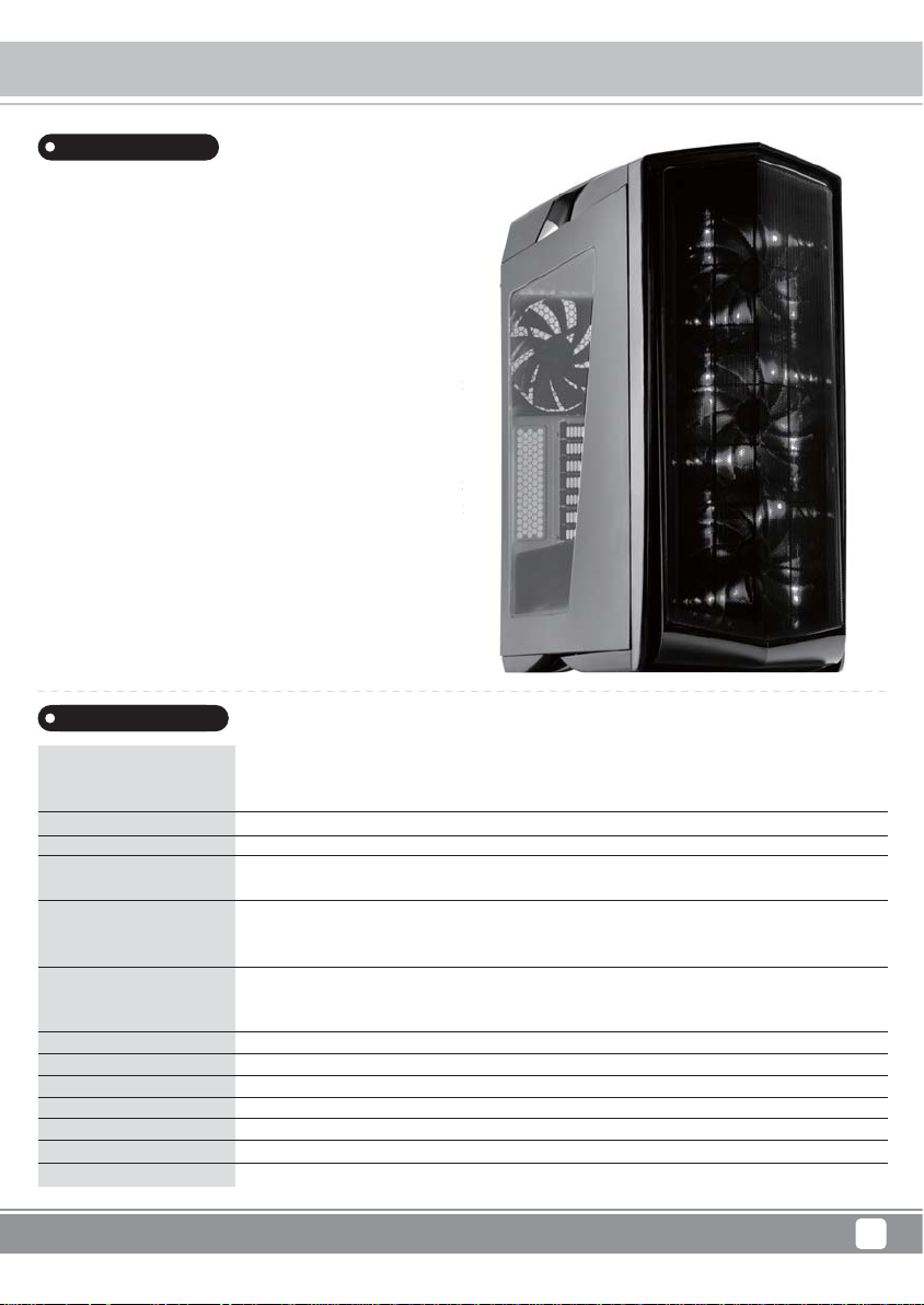
Primera is the Spanish word for “first” or “first class.” Cases in
this series are designed for those seeking to build PCs with rich
feature set and trend-setting aesthetics.
The Primera PM01 is an incredible computer case that fuses
eye-catching styling and functionality in a package rarely seen in the
PC world. It utilizes high quality, piano-like finish with oversized
intake mesh panel inspired by sports car intake grill for unusually
sleek exterior. Paired with an elaborate lighting system consists of
LED fans and built-in adjustable LED strips, the PM01 can project
the feel of a luxurious supercar on a highly customizable computer
case. The roomy interior layout supports a variety of large, high end
components that are designed to be cooled efficiently and quietly
by the included three 140mm LED intake fans and an 140mm exhaust
fan. True to SilverStone tradition, the PM01 also has excellent dust
protection thanks to implementation of easily removable filters and
positive pressure airflow setup. Novice users will find this case a
pleasure to build with and maintain while advanced users will find
details such as support for two 360mm radiator mounting positions
and water tank mounting holes to be highly useful for building beautiful
liquid cooled PCs.
Cases in
with rich
at fuse
en in the
versi
nusually
nsists of
n
omputer
high end
d quietl
exhaust
llent d
lters and
s case a
will find
positions
beautiful
Primera Series PM01
Product Overview
ct
Specifications
Model No.
Material
Motherboard
Drive Bay
Cooling System
Radiator Support
Expansion Slot
Front I/O Port
Power Supply
Expansion Card
Limitation of CPU cooler
Limitation of PSU
Dimension
SST-PM01BR-W (black with red LED + window)
SST-PM01CR-W (matte black with red LED + window)
SST-PM01WA-W (white with blue LED + window)
Plastic outer shell steel body
ATX (up to 12" x 10.7"), Micro ATX
External
Internal
Front
Rear
Top
Front
Rear
Top
7
USB 2.0 x 2, USB 3.0 x 2, Audio x 1, MIC x 1
Standard PS2 (ATX)
Support graphics card up to 16.5", width restriction - 6.88"
180mm
240mm
220mm (W) x 571mm (H) x 560mm (D), 70.3 liters
None
2.5" or 3.5" x 4, 2.5" x 5
3 x 120mm / 140mm fan slot (includes 3 x 140mm LED fan)
1 x 120mm / 140mm fan slot (includes 1 x 140mm fan)
3 x 120mm fan slot or 2 x 140mm fan slot
240mm / 280mm / 360mm x 1
240mm / 280mm / 360mm x 1
120mm / 140mm x 1
1
Page 4
Primera Series PM01
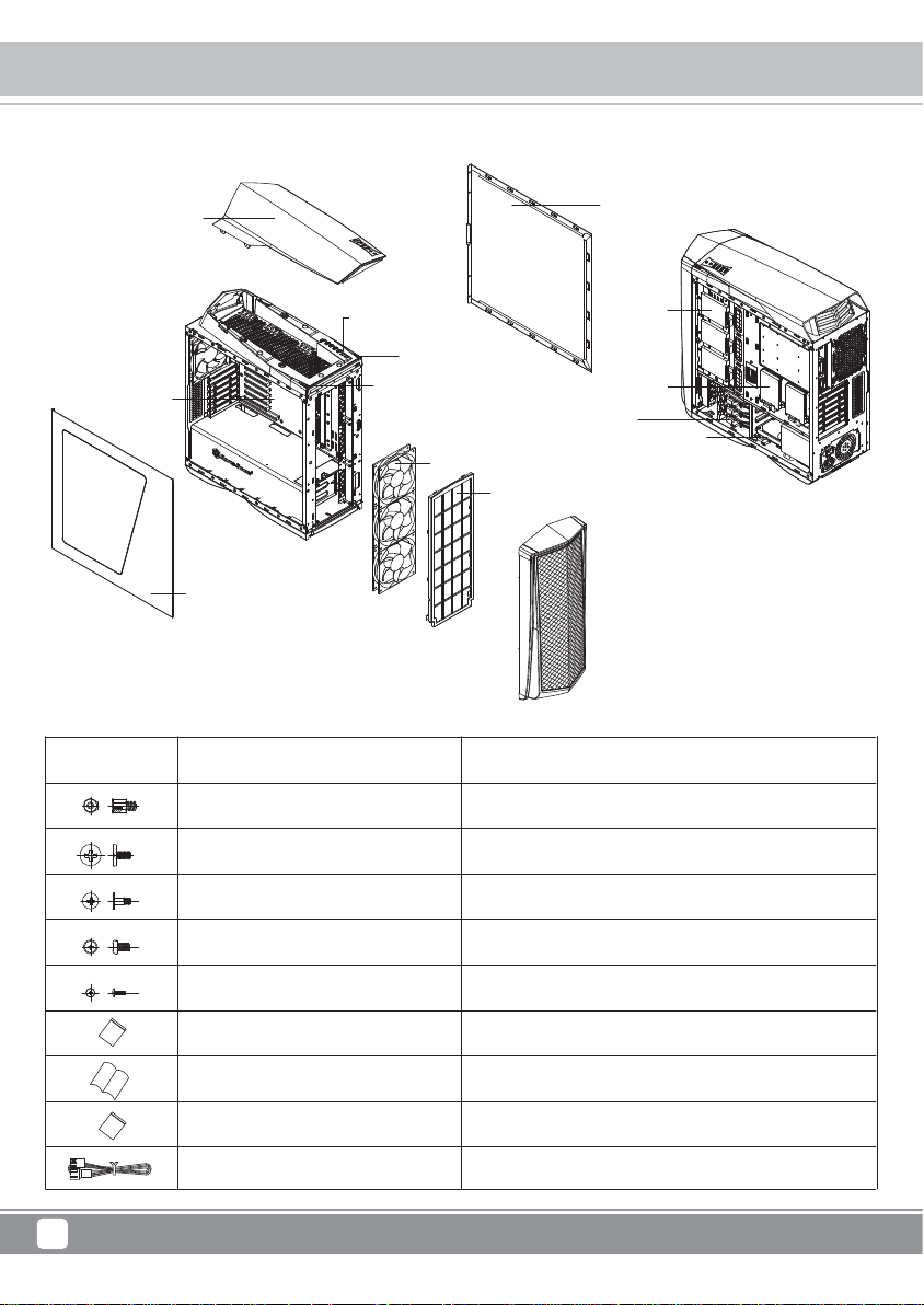
Disassemble Chart
TOP COVER
ATX MB (OPTION)
LEFT-SIDE-PANEL
*Four modes: full brightness, half brightness, breathing pattern, and off
Picture Item
Screw A #6-32 X6.6
USB 3.0 X2, USB 2.0 X2
Audio & MIC port
LED BUTTON *
POWER BUTTON
LED FAN X3
RIGHT-SIDE-P ANEL
2.5” HDD X3
2.5” HDD X2
2.5” or 3.5” HDD X3
2.5” or 3.5” HDD X1
FRONT-FILTER
Purpose
Motherboard Standoff
Screw C #6-32 X5
Screw D #6-32 X15-D=10
Screw B M3 X5
Screw M3-4
Bag 120 x 90MM
Secure Motherboard, PSU, 3.5” HDD
Secure 3.5” HDD
Secure 2.5” HDD
Secured HDD tray
Packing all screws
Manual 205 x 150MM
Bag 170 x 240MM
Fan-Cable-Extension
2
Page 5
Primera Series PM01
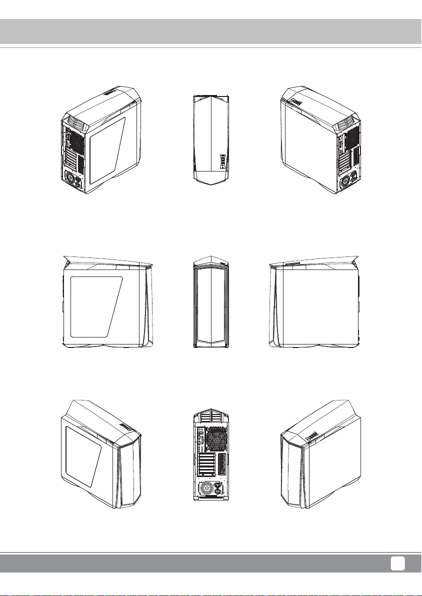
Disassemble Chart
TOP REAR RIGHT 3/4REAR LEFT 3/4
LEFT SIDE
FRONT
REAR
RIGHT SIDE
TOP RIGHTTOP LEFT
3
Page 6
Primera Series PM01
Installation Guide
Before you begin, please make sure that you
1
Have all components collected.
2
Check that all components do not have compatibility problems with each other or with the case.
3
If possible, assemble the components outside the case first to make sure they are working.
Keep the motherboard manual ready for reference during installation.
4
Prepare a Philips screwdriver.
5
01
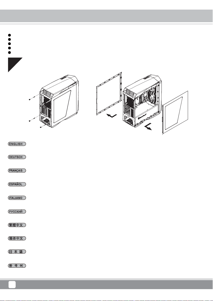
Loosen two screws from both left and right side panels to remove them.
Lösen Sie die beiden Schrauben an den linken und rechten Seitenwänden, nehmen Sie die Seitenwände ab.
Desserrez les vis des deux panneaux latéraux pour les retirer.
Desatornille dos tornillos de los paneles izquierdo y derecho para quitarlos.
Per rimuovere i pannelli laterali allentare, per entrambi, le due viti di serraggio.
Отвинтите по два винта, крепящих левую и правую боковых панели, и снимите панели.
取下左右側板各兩顆螺絲,卸下側板。
取下左右侧板各两颗螺丝,卸下侧板。
両方の左右パネルからネジ2本を緩めて、取り外します。
왼쪽과 오른쪽 사이드 패널에서 두 개씩 나사를 풀어 사이드 패널을 제거합니다.
4
Page 7
02
Insert the I/O shield included with your motherboard.
Installieren Sie das hintere I/O-Blech im Gehäuse.
Installez la plaque arrière de la carte mère dans le boîtier.
Primera Series PM01
Installation Guide
Instale la placa trasera de E/S de la placa base en la carcasa.
Installare la placca I/O della scheda madre nella sede preposta.
Установите в корпус заднюю панель ввода-вывода материнской платы.
將I/O彈片裝上機殼。
将I/O弹片装上机箱。
ケース内にマザーボード後部I/Oプレートをインストールします。
메인보드 후방 I/O 판을 케이스에 장착합니다.
5
Page 8
Primera Series PM01
Installation Guide
03
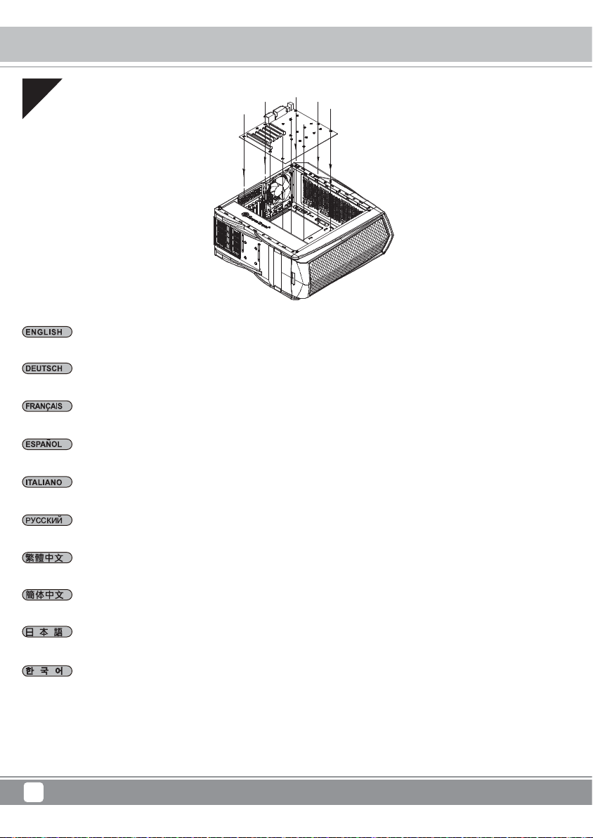
Insert standoffs as required by your motherboard in corresponding mounting holes, then install motherboard.
Stecken Sie die Abstandshalter wie für Ihr Motherboard erforderlich in die entsprechenden Befestigungsbohrungen. Installieren Sie
dann das Motherboard.
Insérez les entretoises comme requis par votre carte mère dans les trous de montage correspondant, puis installez la carte mère.
Inserte los soportes según sea necesario para su placa base en los agujeros de montaje correspondientes, luego instale la placa base.
Inserire nei corrispondenti fori di fissaggio i distanziatori, come richiesto dalla scheda madre, quindi installare la scheda madre.
Принеобходимостиустановите опорныестойкидлясистемной платывсоответствующие крепежныеотверстия, затем
установитесистемнуюплату.
請依需求安裝主機板螺柱,安裝主機板。
请依需求安装主板螺柱,安装主板。
マザーボードに応じて、必要な孔にスペーサーを取り付けてからマザーボードを取り付けます。
메인보드에서 필요한 경우 해당 장착 구멍에 스탠드오프를 삽입한 후 메인보드를 설치합니다.
6
Page 9
04
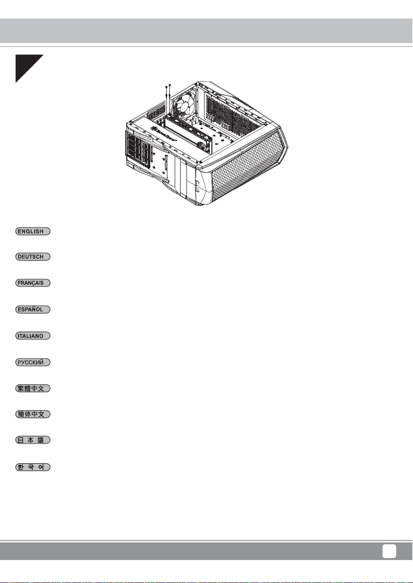
Remove expansion slot covers to install required expansion cards.
Entfernen Sie Steckplatzabdeckungen, installieren Sie die gewünschten Erweiterungskarten.
Retirez les équerres pour installer vos cartes d'extension.
Primera Series PM01
Installation Guide
Quite las cubiertas de los zócalos de expansión para instalar las tarjetas de expansión necesarias.
Rimuovere i cover degli slot di espansione per installare le schede.
Снимите крышки слотов расширения для установки необходимых плат расширения.
移除擴充槽檔片並安裝擴充卡。
移除扩充槽档片并安装扩充卡。
拡張スロットカバーを取り外して、必要な拡張カードを装着します。
확장슬롯 커버를 제거한 후, 필요한 확장카드를 설치 합니다.
7
Page 10

Primera Series PM01
Installation Guide
05
Place your hard drive on the tray and secure with included screws. Caution: the secure with mount of hard drive tray should be place
at the same side with your hard drive connector jack.
Positionieren Sie Ihre Festplatte am Einschub und sichern Sie sie mit den mitgelieferten Schrauben. Achtung: Die Befestigung des
Festplatteneinschubs sollte auf der Seite erfolgen, auf der sich auch der Festplattenanschluss befindet.
Placez votre disque dur sur le plateau et fixez-le avec les vis fournies. Attention : le support du plateau de disque dur doit être du
même côté que la prise du connecteur de disque dur.
Coloque su disco duro en la bandeja y fíjelo con los tornillos incluidos. Aviso: el disco duro montado en la bandeja debería situarse en
el mismo lado de su conector para disco duro.
Collocare il disco rigido nel cassetto e fissarlo utilizzando le viti fornite in dotazione . Attenzione: la parte con le prese del cassetto
contenente il disco rigido deve essere collocata sullo stesso lato del connettore del disco rigido.
Поместите жесткий диск в лоток и закрепите его винтами из комплекта . Внимание! Крепление лотка выполняется
с той же стороны, где расположен соединительный разъем для жесткого диска.
請將您的硬碟安裝置硬碟托盤中,並以內附螺絲鎖固後,請注意鎖固硬碟托盤的方向必須與硬碟連接線接頭一致。
请将您的硬盘安装置硬盘托盘中,并以内附螺丝锁固后,请注意锁固硬盘托盘的方向必须与硬盘连接线接头一致。
ハードディスクをトレイに置き、付属のネジで固定します。注 意: ハ ード ディスクドライブトレイ は 、ハードディスクコ ネクタジャックと同じ
向きに設置してください。
하드 드라이브를 트레이에 올려 놓고 제 공된 나사를 사용하여 고정합니 다. 주의: 하드 드라이브 트레이는 하드 드라이브 커넥터
잭과 동 일한 면에 놓고 장착해야 합니다.
8
Page 11

Installation Guide
06
Install 2.5" drives behind the motherboard tray and secure with screws.
Montieren Sie die 2,5" Laufwerke hinter der Motherboard-Aufnahme und sichern Sie sie mit Schrauben.
Installez des disques de 2,5" derrière le plateau de la carte mère et attachez avec des vis.
Primera Series PM01
Instale los dispositivos de 2,5" tras la bandeja de la placa base y fíjelos con tornillos.
Installare le unità 2,5" dietro il cassetto della scheda madre e fissarle con viti.
За лотком системной платы установите 2,5-дюймовые приводы и закрепите их винтами.
將2.5"硬碟裝上主機板背面,並鎖上螺絲。
将2.5"硬盘装上主板背面,并锁上螺丝。
マザーボードトレイ裏に2.5"ドライブを取り付け、ネジで固定します。
메인보드 트래이 뒤에 2.5" 드라이브를 설치하고 나사로 고정합니다.
9
Page 12

Primera Series PM01
Installation Guide
07
We recommend that you start cable manage now and connect cables such as the ATX 24pin, front I/O connectors, and any other
connectors from front panel devices.
Wir empfehlen, jetzt mit dem Verlegen der Kabel zu beginnen und die 24-poligen ATX-, Front-I/O- und sämtliche weiteren Kabel von
Geräten an der Frontblende anzuschließen.
Nous vous recommandons de commencer à gérer l'organisation des câbles maintenant comment l'ATX 24pin, les connecteurs des
ports E/S de façade, et tout autre connecteur des appareils du panneau frontal.
Le recomendamos que empiece a gestionar el enrutado de cables ahora y conecte cables como el ATX 24 pines, los conectores
frontales E/S y cualquier otro conector de los dispositivos del panel frontal.
Vi raccomandiamo di iniziare subito la sistemazione delle connessioni e collegare quindi i connettori relativi ai cavi ATX 24pin, alle
connessioni I/O frontali e qualsiasi altro collegamento delle periferiche poste frontalmente.
На этом этапе рекомендуется начать прокладку кабелей и подсоединить кабели, например кабель ATX с 24-контактным
разъемом, разъемы ввода-вывода передней панели и любые другие разъемы от устройств на передней панели.
我們建議您可以在此時開始理線,請先安上ATX24Pin接線,Front panel controller 與Front I/O。
我们建议您可以在此时开始理线,请先安上ATX24Pin接线,Front panel controller 与Front I/O。
この時点でケーブ ル取り回しを考えながら、ATX24ピン、フロントI/Oコネクタ、その他フロントパネルデバイスからのコネクタ類のケーブ
ルを 接続 するようお勧 めします。
이 단계에서부터 ATX 24핀, 전면 I/O 커넥터, 그리고 전면 패널에서의 다른 커넥터 등 케이블 정리를 하시기를 권장합니다.
10
Page 13

08
Connect all cables and wires.
Schließen Sie alle Kabel an.
Branchez tous les câbles et les fils.
Primera Series PM01
Installation Guide
Conecte todos los cables.
Collegare tutti i cavi ed i fili.
Подключите все кабели и провода.
連接所有線材。
连接所有线材。
ケーブルとリード線を全て接続します。
모든 케이블과 전선을 연결합니다.
11
Page 14

Primera Series PM01
Installation Guide
09
Install power supply into the case.
Bauen Sie das Netzteil ins Gehäuse ein.
Installez la source d’alimentation dans le châssis.
Instale la fuente de alimentación en la carcasa.
Installazione dell’alimentatore nel case.
Установите в корпус блок питания.
安裝電源。
安装电源。
電源をケースに取り付けます。
전원 공급장치를 케이스에 설치합니다.
12
Page 15

10
Reinstall side panels back onto the case.
Bringen Sie die Seitenteile wieder an.
Réinstallez les panneaux latéraux sur le chassis.
Primera Series PM01
Installation Guide
Reinstale los paneles laterales de nuevo en la carcasa.
Reinstallare sul case i pannelli laterali.
Установите на место боковые панели корпуса.
裝回左右側板。
装回左右侧板。
ケースに側面パネルをもどします。
측면 패널을 케이스에 도로 설치합니다.
13
Page 16

Primera Series PM01
Top Cover Removed Guide
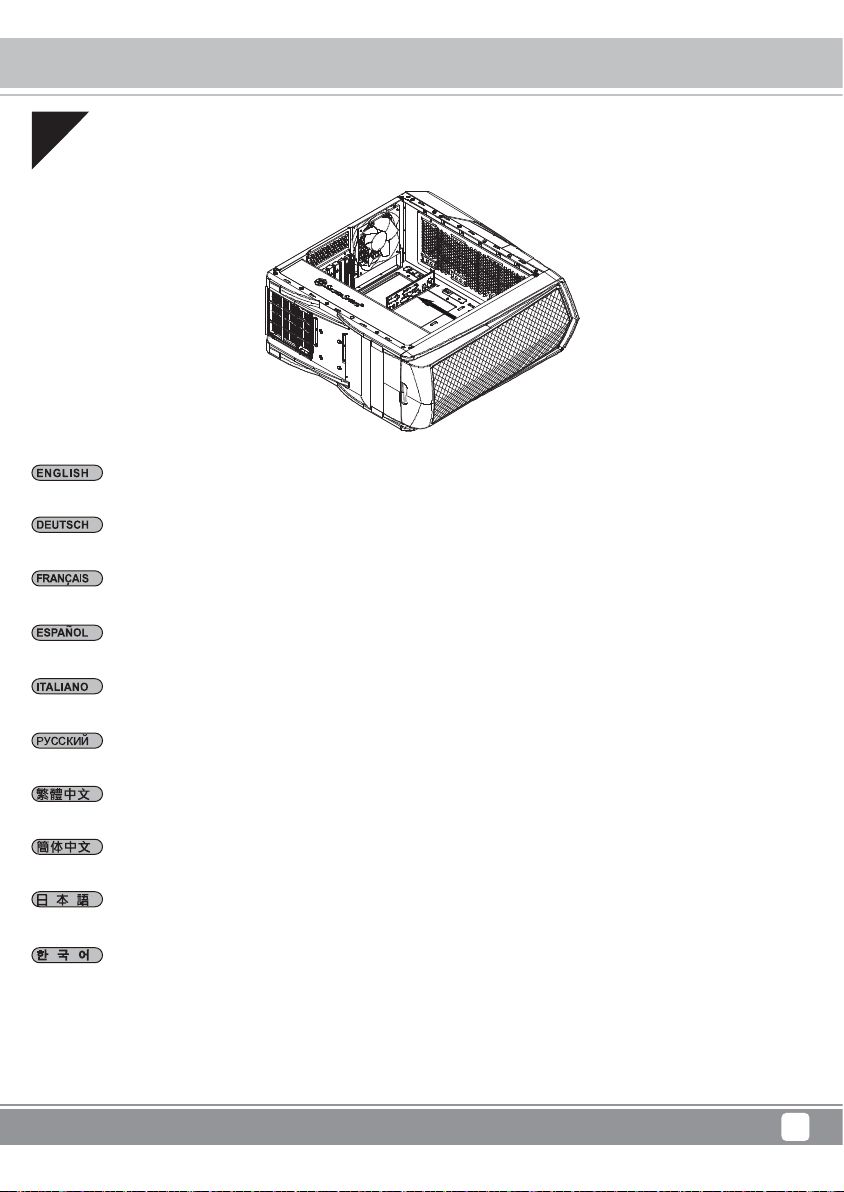
Loosen side screws then push up to remove the top cover.
Lösen Sie die seitlichen Schrauben; entfernen Sie dann die obere Abdeckung, indem Sie sie nach oben drücken.
Desserrer les vis latérales puis poussez pour retirer le couvercle supérieur.
Afloje los tornillos laterales y luego empuje hacia arriba para retirar la cubierta superior.
Allentare le viti laterali, quindi spingere verso l'alto per rimuovere la copertura superiore.
Открутите боковые винты, затем потяните вверх чтобы снять верхнюю крышку.
移除側邊螺絲後,往上輕輕施力即可拔起上蓋。
移除侧边螺丝后,往上轻轻施力即可拔起上盖。
側面のネジを緩めてから上に押して上面カバーを外します。
측면 나사를 플고 상부 커버를 밀어 올려 제거합니다.
14
Page 17

Primera Series PM01
Connector Definition
(1) Fort panel connector installation
Power switch installation guide:
Please refer to the motherboard manuals for the motherboard’s “Front Panel Connector” or “System Panel Connector” pin definition.
Power switch have no polarity, so they can be connected in any orientation.
Ein-/Ausschalter und installieren:
Bitte suchen Sie in der Motherboard-Dokumentation nach der Pinbelegung der Anschlüsse des Frontbedienfeldes („Front Panel
Connectors“ oder „System Panel Connectors“). Ein-/Austaste und benötigen keine bestimmte Polarität, können daher beliebig (ohne
auf + und - zu achten) angeschlossen werden.
Guide d'installation des interrupteurs d'allumage:
Veuillez-vous référer au manuel de votre carte mère pour la description des broches "des connecteurs du panneau frontal" et des
broches "des connecteurs du panneau système". Les interrupteurs d'allumage ne possède pas de polarité, donc ils peuvent être
branché dans les deux sens.
Guía de instalación de los interruptores :
Por favor, consulte en los manuales de la placa base la configuración de pines del “Conector de panel frontal” ó “Conector de
panel de sistema” de su placa base. Los interruptores no tienen polaridad, luego se pueden conectar con cualquier orientación.
Guida all’installazione dei connettori Power Switch:
Fare riferimento al manuale della scheda madre nella sezione “Connettori del pannello frontale” o “Connettori del pannello di sistema”.
Power switch non hanno polarità, posso essere pertanto connessi con qualsiasi orientamento.
Инструкция по подключению выключателя питания и кнопки:
Описание контактов разъемов приведены в разделах “Разъемы передней панели” или “Разъемы системной панели” руководства
пользователя материнской платы. Выключатель питания и кнопка не имеют полярности, поэтому их можно подключать в любой ориентации.
Power Switch安裝說明:
請參考主機說明書的Front Panel Connectors安裝Pin Define,將Connector插上;Power Switch並無正負極性之分, 反插正插都不影響功能性。
Power Switch安装说明:
请参考主机说明书的Front Panel Connectors安装Pin Define,将Connector插上;Power Switch并无正负极性之分, 反插正插都不影响功能性。
電源スイッチおよのインストールガイド:
マザーボードの「フロントパネルコネクタ」または「システムパネルコネクタ」のピン配列についてはマザーボードマニュアルを参照してく
ださい。電源スイッチとに極性はないので、いずれの方向でも接続できま。
파워 스위치 스위치 설치 가이드 메인보드 매뉴얼의 전면패널 커넥터 혹은
시스템패널 커넥터 핀을 참조하기 바랍니다. 파워 스위치와 스위치는 극성이 없어 어떤 방향으로 설치해도 무방합니다.
15
Page 18

Primera Series PM01
Connector Definition
LED connector installation guide
Please refer to the motherboard manuals for the motherboard’s “Front Panel Connector” or “System Panel Connector” pin definition.
White colored wires are negative while other colored wires are positive. Power LED connector is made to be individual pins by design
to accommodate different motherboard specifications.
Bitte suchen Sie in der Motherboard-Dokumentation nach der Pinbelegung der Anschlüsse des Frontbedienfeldes („Front Panel Connectors“
oder „ System Panel Connectors“). Die weißen/ schwarz Adern sind negativ (-), die farbigen Adern positiv (+).Die Kabel für die
Betriebsanzeige-LED sind zur Kompatibilität mit unterschiedlichsten Motherboards einzeln, nicht als kompletter Stecker ausgeführt.
Achten Sie hier bitte auf die richtige Polarität, lesen Sie in der Dokumentation Ihres Motherboards nach.
Veuillez-vous référer au manuel de votre carte mère pour la description des broches "des connecteurs du panneau frontal" et des
broches "des connecteurs du panneau système". Les câbles colorés en blanc/noir sont négatifs alors que ceux d'une autre couleur sont
positifs. Les câbles de la LED Power sont séparés afin d'être compatible avec différentes cartes mères, donc vérifiez bien qu'ils sont
branchés avec la bonne polarité en vous référant au manuel de votre carte mères.
Por favor, consulte en los manuales de la placa base la configuración de pines del “Conector de panel frontal” ó “Conector de panel de
sistema” de su placa base. Los cables de color blanco/negro son negativos mientras que los de color son positivos. Los cables LED de
potencia tienen pines separados para compatibilidad con diferentes definiciones de pines de la placa base luego por favor, asegúrese de
que están conectados en la polaridad correcta consultando el manual de su placa base.
Fare riferimento al manuale della scheda madre nella sezione “Connettori del pannello frontale” o “Connettori del pannello di sistema”.
I cavi di colore bianco/nero sono il polo negativo, mentre quelli di colore diverso il positivo.
Описание контактов разъемов приведены в разделах “Разъемы передней панели” или “Разъемы системной панели” руководства
пользователя материнской платы. Белые/черный провода - отрицательно й полярности, цветные провода - положительной
полярности. Провода светодиодного индикатора питания имеют отдельные контакты для совместимости с различными типами
контактов материнских плат, поэтому обратитесь к руководству пользователя материнской платы и убедитесь, что
соблюдена.
請參考主機說明書的Front Panel Connectors安裝Pin Define,將Connector插上;白/黑色線的部分為負極,彩色線的部分是正極。
Power LED為了適 應各主機板的不同, 特別設計為散Pin樣式,請安心使用。
请参考说明书的Front Panel Connectors安装Pin Define,将Connector插上;白/黑色线的部份为负极,彩色线的部份为正极。
Power LED为了适应主机 板的不同, 特别设计为散Pin样式,请安心使用。
マザーボードの「フロントパネルコネクタ」または「システムパネルコネクタ」ピン配列についてはマザーボードマニュアル参照してくださ
い。白/黑色のリード 線は マイナスで、色の着いたリード線がプラスです。電源LEDリード線は種々のマザーボードピン定義と互換性を持た
せるため分離されたピンとなっているので、ご使用のマザーボードマニュアルを参照して、適切な極性に接続されるようお確かめください。
메인보드 매뉴얼의 전면패널 커넥터 혹은 시스템패널 커넥터 핀을 참조하기 바랍니다. 하얀/검은선의 경우 음극이며, 다른 색의
경우 양극입니다. 파워 LED 선은 분리되어 다양한 메인보드에서 동작할 수 있도록 되어 있습니다. 그러므로 메인보드 매뉴얼을
참조하여 올바를 극성을 주의해 선택하시기 바랍니다.
полярность
16
Page 19

Primera Series PM01
Connector Definition
(2) Front I/O connecter Guide
Below are the front I/O connectors pin definition, please also check your motherboard manual to cross reference with motherboard’s front I/O pin
headers. SilverStone’s I/O connectors are in block type to simplify installation.
Nachstehend finden Sie die Pinbelegung der vorderen E/A-Anschlüsse; bitte gleichen Sie zudem das Handbuch Ihres Motherboards
mit den vorderen E/A-Pinzuweisungen ab. SilverStones E/A-Anschlüsse befinden sich zur Vereinfachung der Installation in Blockart.
Au dessous de la description des broches des ports d'E/S, veuillez aussi vérifier sur le manuel de votre carte mère de manière croisée que les
broches sont correctement placées. Les connecteurs d'E/S de SilverStone sont en bloc pour en simplifier leur installation.
A continuación se detallan los pines para conectores E/S frontales, compruebe también por favor el manual de su placa base para cotejar los pines
E/S frontales de la misma. Los conectores E/S de SilverStone son del tipo bloque para simplificar la instalación.
Di seguito lo schema delle connessioni I/O frontali, confrontare lo schema con quanto riportato sul manuale della scheda madre per effettuare un
controllo incrociato. I connettori I/O Silverstone, per semplificare l’installazione, sono del tipo “a blocco”.
Ниже приведено описание контактов передних разъемов ввода/вывода. Обратитесь также к руководству пользователя материнской платы
за описанием передних разъемов ввода/вывода типа "пин-хедер". Разъемы ввода/вывода "SilverStone" - блочного типа, что облегчает сборку
下表為Front I/O Connectors的Pin Define,請參閱主機板說明書的各Front I/O Connectors Pin Define一一核對。 PM01的Front I/O Connectors
完全採用集合Pin方式以簡化安裝。
下表为Front I/O Connectors的Pin Define,请参阅主机板说明书的各Front I/O Connectors Pin Define一一核对。 PM01的Front I/O Connectors
完全采用集合Pin方式以简化安装。
以下はフロントI/Oコネクタピン配列ですが、お持ちのマザーボードのフロントI/Oピンヘッダは、マザーボードマニュアルをご参照ください。シルバース
トーンの I/ Oコネクタは、インストールの容易なブロックタイプになっています。
아래는 전면 I/O 커넥터의 핀 사양입니다. 메인보드 매뉴얼을 참조해, 메인보드의 전면 I/O 핀사양을 재 확인한 후 설치합니다. SilverStone의 I/O
커넥터는 블록 타입으로 구성되어 있어 간편한 설치가 가능합니다.
USB 3.0 CONNECTOR HD CONNECTOR
Pin 1
Vbus
IntA_P1_SSRX-
IntA_P1_SSRX+
GND
IntA_P1_SSTX-
IntA_P1_SSTX+
GND
IntA_P1_D-
IntA_P1_D+
ID
Pin 19
Vbus
IntA_P2_SSRXIntA_P2_SSRX+
GND
IntA_P2_SSTXIntA_P2_SSTX+
GND
IntA_P2_DIntA_P2_D+
Pin 11Pin 10
17
Page 20

Primera Series PM01
Component Size Limitations
The PM01 was designed to accommodate oversized components, but we still recommend referring to the
following dimension guidelines:
(1) CPU Cooler limitation
180MM
9MM
33MM
Height limitation for CPU cooler is 180mm with 33mm clearance over the motherboard’s top edge.
Höhenbeschränkung für CPU-Kühler 180 mm mit einem Freiraum von 33 mm oberhalb der Motherboard-Oberkante.
La limitation de hauteur des refroidisseurs de processeurs est 180mm avec un espace de 33mm au-dessus du bord supérieur de la carte
La limitación de altura para disipadores de CPU es de 180mm con un espacio libre de 33mm sobre el borde superior de la placa base.
La limitazione dell’altezza del dissipatore di calore CPU è di 180 millimetri con uno spazio libero di 33 mm sopra il bordo superiore della scheda madre.
Ограничение по высоте для системы охлаждения процессора составляет 180 мм с 33-мм зазором над верхним краем системной платы.
Cooler限高是180mm,Cooler外緣允許超出主機板上邊界33mm。
Cooler限高是180mm,Cooler外缘允许超出主板上边界33mm。
mères
.
CPUクーラーの高さ限度は、マザーボード上側の余裕33mmを取って、180mmです。
CPU 쿨러의 높이 제한은 180mm로서 메인보드 상단 가장자리 위로의 허용 오차가 33mm입니다.
18
Page 21

Component Size Limitations
(2) Power supply limitation
The PM01 supports power supply with depth of up to 240mm.
Das PM01 unterstützt Netzteile mit einer Tiefe von bis zu 240 mm.
Le PM01 est compatible avec les alimentations d'une profondeur inférieure ou égale à 240mm.
La PM01 acepta fuentes de alimentación con una profundidad de hasta 240mm.
PM01 supporta alimentatori con profondità fino a 240mm.
Корпус PM01 допускает установку блока питания глубиной до 240 мм.
PM01的電源可用總空間有240mm。
Primera Series PM01
PM01的电源可用总空间有240mm。
PM01は最高240mmの奥行きの電源をサポートします。
PM01은 240mm의 깊이를 갖는 파워 서플라이까지 지원합니다.
22.6MM
240MM
19
Page 22

Page 23

(4) Liquid cooling radiator limitations
Primera Series PM01
Component Size Limitations
120MM, 140MM
240MM, 280MM
360MM
120MM, 140MM
140MM
360mm Radiator limitation
120MM
35.55MM
72.9MM
330MM
71.4MM
240MM, 280MM
360MM
45MM
6.6MM
21
Page 24

Primera Series PM01
Upgrade and Mainterance
Illustration: An example of a GPU cooler that is filled with dust and has lost most of its cooling performance PM01’s positive air pressure design is
an effective configuration that will reduce dust buildup inside the case. Small air particles or lint will accumulate over time on intake filters instead
of on the components inside the case. To maintain PM01’s excellent cooling performance for years to come, we recommend to clean all fan filters
regularly every three months or half a year (depending on your environment).
Das vorteilhafte Luftdruckdesign des PM01 ist eine effektive Konfiguration, die Staubablagerungen innerhalb des Gehäuses vermindert. Im Laufe
der Zeit sammeln sich kleine Partikel und Fusseln an den Luftzufuhrfiltern, anstatt an den Komponenten im Gehäuseinneren, an. Sie können eine
jahrelange optimale Kühlleistung des PM01 gewährleisten, indem Sie alle Lüfterfilter regelmäßig alle drei bis sechs Monate reinigen (je nach
Umgebungsbedingungen).
La conception à pression d'air positive du PM01 est une configuration efficace permettant de réduire l'accumulation de la poussière dans le boîtier.
De petites particules d'air ou de peluche vont s'accumuler avec le temps sur les filtres d'aspiration, et non sur les composants à l'intérieur du boîtier.
Pour conserver les excellentes performances de refroidissement du PM01 au fil des ans, nous vous recommandons de nettoyer l'ensemble des
filtres des ventilateurs, tous les trois ou six mois (selon votre environnement).
El diseño de presión de aire positiva de la PM01 es una configuración efectiva que reducirá la acumulación de polvo dentro de la carcasa. Pequeñas
partículas de polvo ó pelusa se irán acumularán con el transcurso del tiempo en los filtros de entrada en lugar de en los componentes del interior
de la carcasa. Para mantener la excelente capacidad de refrigeración de la PM01 en años venideros, le recomendamos que limpie con regularidad
todos los filtros de los ventiladores cada tres meses ó seis meses (dependiendo de dónde viva).
Il design a pressione positiva di PM01 riduce considerevolmente gli accumuli di polvere all’interno del case. Le piccole particelle si accumulano
infatti sui filtri invece che sui componenti interni. Per mantenere le eccellenti prestazioni di raffreddamento di PM01 negli anni a venire vi
raccomandiamo di procedere ad una regolare pulizia dei filtri (con cadenza trimestrale o semestrale dipendentemente dall’ambiente un cui è
disposto il sistema).
Конструкция корпуса PM01 обеспечивает избыточное давление воздуха и, таким образом, имеет эффективную конфигурацию, препятствующую
скоплению пыли внутри корпуса. Небольшие частицы и волокна, содержащиеся в воздухе, со временем будут скапливаться на впускных
фильтрах, а не на компонентах, находящихся внутри корпуса. Для поддержания превосходного охлаждения компонентов в корпусе PM01
в течение многих лет рекомендуется
условий окружающей среды).
圖:被灰塵卡死的顯示卡散熱器 PM01的正壓差搭配濾網方式是經的起時間考驗最有效的防塵方式。在使用相當長一段時間後,棉屑灰塵或其他可能妨
礙散熱效能的小異物只會卡在濾網,而不是電腦內的元件上面。我們重視的散熱效能,是在您使用電腦長達2~3年後還能維持與全新的無異。為了維持
這種散熱效能您只需要定期清理濾網,而不是電腦裡面的元件。 視環境而定,我們建議您每6個月~1年必須清理濾網。
图:被灰尘卡死的显示卡散热器 PM01的正压差搭配滤网方式是经的起时间考验最有效的防尘方式。在使用相当长一段时间后,棉屑灰尘或其他可能妨
碍散热效能的小异物只会卡在滤网,而不是计算机内的组件上面。我们重视的散热效能,是在您使用计算机长达2~3年后还能维持与全新的无异。为了
维持这种散热效能您只需要定期清理滤网,而不是计算机里面的组件。 视环境而定,我们建议您每6个月~1年必须清理滤网。
PM01の正圧設計は、ケース内のホコリの蓄積を減少させる有効な構造です。時と共に空気中の微粒子または糸くずはケース内のコンポーネト上の代わ
りに取 入 れ 口フィルタに 溜まります。この先何年もの間RV05の素晴らしい冷却性能を維持するには、全てのファンを3ヶ月ないしは半年(環境に依存)ごと
に規則的に清掃するようお勧めします。
PM01의 양압 디자인은 케이스 내부에 먼지가 싸이는 것을 방지 하기 위한 효과적인 디자인입니다. 작은 분진이나 먼지는 케이스 내부에 있는필터에
시간에 따라 쌓이게 됩니다. PM01의 우수한 냉각 성능을 계속 유지하기 위헤서 매 3개월 혹은 6개월(사용환경에 따라)마다 필터 청소를권장합니다.
регулярно очищать все фильтры вентиляторов: раз в 3 месяца или раз в полгода (в зависимости от
22
Page 25

(2) Fan removal guide
Primera Series PM01
Upgrade and Mainterance
Step 1
Step 3
Remove main filter, Unscrew screws holding the fans to remove them.
Entnehmen Sie den Hauptfilter, Lösen Sie die Befestigungsschrauben des Lüfters, nehmen Sie sie heraus.
Enlevez le filtre principal, Dévissez les vis des ventilateurs pour les enlever.
Retire filtro principal, Suelte los tornillos que soportan los ventiladores para retirarlos.
Step 2
Step 4
Rimuovere il filtro principale, Svitare le viti che fissano le ventole per rimuoverle.
Снимите главный фильтр, Чтобы извлечь вентиляторы, отверните винты их крепления.
移除主濾網,卸除固定風扇的螺絲,卸除風扇。
移除主滤网,卸除固定风扇的螺丝,卸除风扇。
メインフィルターを取り外します,ファンを固定しているネジを 外して、取り外します。
주 필터를 분리합니다,팬을 고정하는 나사를 풀어 팬을 분리합니다.
23
Page 26

Primera Series PM01
Upgrade and Mainterance
(3) Fan filter purchase process
If you accidentally loose/damage filters or need additional ones for backup, please contact your local SilverStone retailers or distributors
for purchasing information:
http://www.silverstonetek.com/wheretobuy_all.php
Wenn Sie einen Lüfterfilter als Zusatz, zum Austausch bei Verlust oder Beschädigung oder einfach als Reserve erwerben möchten, suchen Sie
einfach auf unseren Internetseiten nach einem Händler oder Distributor in Ihrer Nähe:
http://www.silverstonetek.com/wheretobuy_all.php
Pour acheter un filtre du ventilateur au détail comme pour l’améliorer ou pour le remplacer en caisson de perte, de dommage ou simplement en
rechange, vous pouvez rechercher sur notre site Internet pour connaître les revendeurs ou les distributeurs les plus proches de chez vous:
http://www.silverstonetek.com/wheretobuy_all.php
Para comprar un filtro para ventilador como mejora o reemplazo en caso de pérdida, daño o simplemente como recambio, puede buscar en nuestra
página web para encontrar el distribuidor o vendedor autorizado más cercano:
http://www.silverstonetek.com/wheretobuy_all.php
Per acquistare un filtro della ventola al dettaglio per la sostituzione in caso di perdita, danni o semplicemente uno di riserva, è possibile cercare sul
nostro sito web i rivenditori o distributori più vicini:
http://www.silverstonetek.com/wheretobuy_all.php
На нашем сайте Вы найдете ближайшего торгового посредника или дистрибьютора, у которого можно приобрести фильтр вентилятора для
замены в случае потери или повреждения старого фильтра, или про запас.
http://www.silverstonetek.com/wheretobuy_all.phpA
添購濾網如果您不慎遺失、人為損壞或只是想要多購買濾網備用。請與我們的經銷點聯絡進行購買。請上SilverStone網站查詢各區域經銷:
http://www.silverstonetek.com.tw/wheretobuy_all.php?area=tw
添购滤网如果您不慎遗失、人为损坏或只是想要多购买滤网备用。请与我们的经销点联络进行购买。请上SilverStone网站查询各区域经销:
http://www.silverstonetek.com/warranty.php?area=cn
アップグレードまたは損失の場合の交換用、または単にバックアップとして小売ファン・フィルタを購入するには、最寄りの小売業者または卸売業者を下
記の当社ウェブサイトから検索できます:
http://www.silverstonetek.com/wheretobuyall.phpA
팬 필터가 분실 또는 손상되어 소매로 팬 필터를 구입하거나 단순히 여분으로 구입하려는 경우, 당사의 웹사이트에서 가까운 판매점을 검색할 수
있습니다.
http://www.silverstonetek.com/wheretobuy_all.php
24
Page 27

Warranty Information
This product has a limited 1 year warranty in North America and Australia.
For information on warranty periods in other regions, please contact your reseller or SilverStone
authorized distributor.
Warranty terms & conditions
1. Product component defects or damages resulted from defective production is covered under warranty.
Defects or damages with the following conditions will be fixed or replaced under SilverStone Technology’s jurisdiction.
a) Usage in accordance with instructions provided in this manual, with no misuse, overuse, or other inappropriate actions.
b) Damage not caused by natural disaster (thunder, fire, earthquake, flood, salt, wind, insect, animals, etc…)
c) Product is not disassembled, modified, or fixed. Components not disassembled or replaced.
d) Warranty mark/stickers are not removed or broken.
Loss or damages resulted from conditions other than ones listed above are not covered under warranty.
2. Under warranty, SilverStone Technology’s maximum liability is limited to the current market value for the product (depreciated value, excluding
shipping, handling, and other fees). SilverStone Technology is not responsible for other damages or loss associated with the use of product.
3. Under warranty, SilverStone Technology is obligated to repair or replace its defective products. Under no circumstances will SilverStone
Technology be liable for damages in connection with the sale, purchase, or use including but not limited to loss of data, loss of business, loss of
profits, loss of use of the product or incidental or consequential damage whether or not foreseeable and whether or not based on breach of warranty,
contract or negligence, even if SilverStone Technology has been advised of the possibility of such damages.
4. Warranty covers only the original purchaser through authorized SilverStone distributors and resellers and is not transferable to a second hand
purchaser.
5. You must provide sales receipt or invoice with clear indication of purchase date to determine warranty eligibility.
6. If a problem develops during the warranty period, please contact your retailer/reseller/SilverStone authorized distributors or SilverStone
http://www.silverstonetek.com.
Please note that: (i) You must provide proof of original purchase of the product by a dated itemized receipt; (ii) You shall bear the cost of shipping
(or otherwise transporting) the product to SilverStone authorized distributors. SilverStone authorized distributors will bear the cost of shipping
(or otherwise transporting) the product back to you after completing the warranty service; (iii) Before you send the product, you must be issued a
Return Merchandise Authorization (“RMA”) number from SilverStone. Updated warranty information will be posted on SilverStone’s official website.
Please visit http://www.silverstonetek.com for the latest updates.
Additional info & contacts
For North America (usasupport@silverstonetek.com)
SilverStone T echnology in North America may repair or replace defective product with refurbished product that is not new but has been functionally tested.
Replacement product will be warranted for remainder of the warranty period or thirty days, whichever is longer. All products should be sent
back to the place of purchase if it is within 30 days of purchase, after 30 days, customers need to initiate RMA procedure with SilverStone Technology
in USA by first downloading the “USA RMA form for end-users” form from the below link and follow its instructions.
http://silverstonetek.com/contactus.php
For Australia only (support@silverstonetek.com)
Our goods come with guarantees that cannot be excluded under the Australian Consumer Law.
You are entitled to a replacement or refund for a major failure and for compensation for any other reasonably foreseeable loss or damage.
You are also entitled to have the goods repaired or replaced if the goods fail to be of acceptable quality and the failure does not amount to a major failure.
Please refer to above “Warranty terms & conditions” for further warranty details.
SilverStone Technology Co., Ltd. 12F No. 168 Jiankang Rd., Zhonghe Dist., New Taipei City 235 Taiwan R.O.C. + 886-2-8228-1238
(standard international call charges apply)
For Europe (support.eu@silverstonetek.de)
For all other regions (support@silverstonetek.com)
Page 28

G11226881
 Loading...