

Page 1
Milo Series
The Mini-ITX HTPC benchmark
ML09
Page 2

Page 3
Installation and system optimization guide:
The following manual and guides were carefully prepared by the SilverStone engineering team to
help you maximize the potential of your SilverStone product. Please keep this manual for future
reference when upgrading or performing maintenance on your system. A copy of this manual can also
be downloaded from our website at:
Product Overview
Special Features
Specification
Disassemble Chart
Installation Chart
Connector Definition
Componet Size Limitations
Upgrade And Maintenance
P.1
P.1
P.1
P.2
P.3
P.18
P.21
P.28
Warranty Information
Page 4
Milo Series ML09
Product Overview
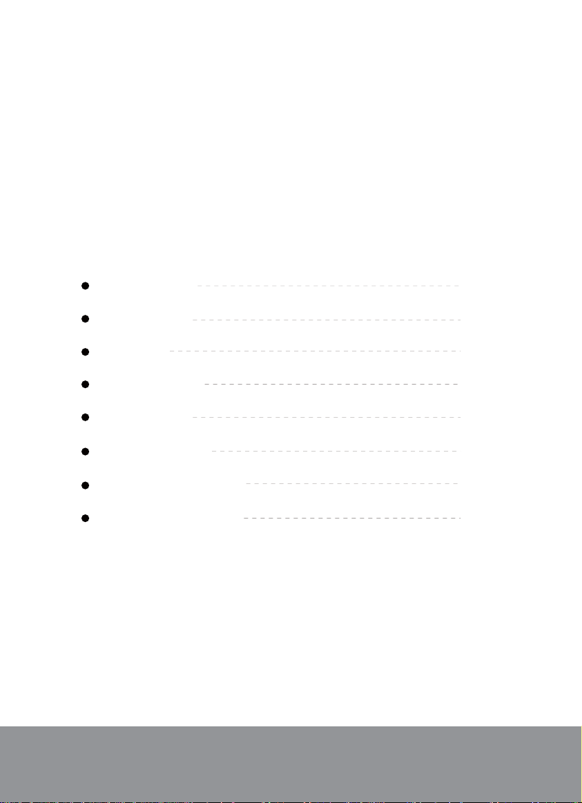
Introduction
The ML09 is an evolution and variation of the premium Mini-ITX HTPC case, the Milo ML06. With external dimension unchanged at
7 liters, the ML09 rearranged internal layout provides a crucial second expansion slot for support of more powerful low-profile discrete
graphics card or expansion card that are two slots wide. For users that wish to build with a more robust GPU or tuner card in console/
DVR-like form factor to game or for multimedia content recording, the ML09 is a great starting point.
Special Features
Super small at only 7 liters
Premium styling front panel with mirror finish
Includes one 120mm fan and support up to two 80mm fans
Multipurpose 4-in-1 bracket
Support Mini-ITX motherboard and SFX power supply
Support dual slot low-profile graphics or expansion card
Support four 2.5” HDD/SSD
Specifications
Model
Material
Motherboard
Drive Bay
Cooling System
Expansion Slot
Front I/O Port
Limitation of CPU cooler
Power Supply
Expansion Card
Dimension
Extra
1
SST-ML09B (black)
Acrylic and plastic front panel, 0.8mm steel body
Mini-ITX,Mini-DTX
Exposed
Internal
Side
Top
2
USB 3.0 x 2, Audio x 1, MIC x 1
37~70mm (variable based on use of multipurpose bracket)
1 x Optional standard SFX
Single or dual slot low profile up to 6.9”, width restriction-2.95"
350mm (W) x 99 mm (H) x 205 mm (D), 7 liters
Support Kensington lock
Slim optical 12.7mm or 9.5mm x 1 (9.5mm compatibility limited to tray type)
(replaceable with 3.5” HDD x 1, 2.5” HDD x 2,or 120mm fan x 1)
2.5” x 4
2 x 80mm fan slot
1 x 120mm fan, 1500rpm, 18dBA
Page 5
TOP FILTER (FF143)
Milo Series ML09
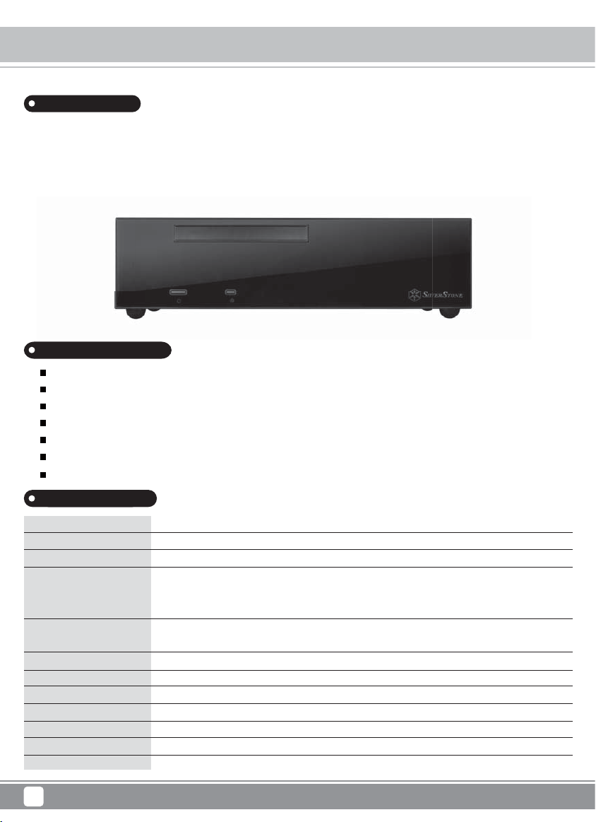
Disassemble Chart
TOP COVER
12015 FAN
MULTIPURPOSE * 4 + IN - 1 BKT
BASE
MB (NOT INCLUDED)
LOW PROFILE EXPANSION CARD (NOT INCLUDED)
8025 FAN * 2 (NOT INCLUDED)
USB 3.0 * 2 + Audio + MIC
PICTURE ITEM PURPOSE
MANUAL
ZIPPER BAG
BUNCH WIRE TIES
FF143 - FILTER
ZIPPER BAG
FAN RUBBER PADDING
SCW - 6 - 32
CENTER BRACE
SFX PSU
RESET BUTTON
POWER BUTTON
2.5” HDD CAGE
USER INSTALLATION GUIDE
CONTAINS PARTS AND SCREWS
CABLE MANAGEMENT
FAN FILTER FOR TOP COVER 120MM FAN SLOT
CONTAINS FF143-FILTER AND MANUAL
RUBBER PADDING FOR 120MM FAN ON MULTIPURPOSE
BRACKET
SECURE MOTHERBOARD, PSU AND 3.5” DRIVES
2.5” HDD * 4
(NOT INCLUDED)
SCW - M3
SCW - M2
RUBBER
FOOT RUBBER
BUTTOM FOOT
SPRING RUBBER
95 TO 127-PANEL-BK
9-5-MYLAR
SECURE 2.5” DRIVES
SECURE 9.5MM/12.7MM SLIM SLOT-LOADING OPTICAL DRIVE
HORIZONTAL ANTI-VIBRATION BOTTOM RUBBER FEET
VERTICAL STAND ACCESSORY
VERTICAL STAND ACCESSORY
VERTICAL STAND ACCESSORY
Replaceable bezel for 9.5mm slim optical drive to eliminate excess
front panel gap.
Stick on to increase 9.5mm slim optical drive thickness.
2
Page 6
Milo Series ML09
Installation Chart
Before you begin, please make sure that you
1
Have all components collected.
2
Check that all components do not have compatibility problems with each other or with the case.
3
If possible, assemble the components outside the case first to make sure they are working.
Keep the motherboard manual ready for reference during installation.
4
Prepare a Philips screwdriver.
5
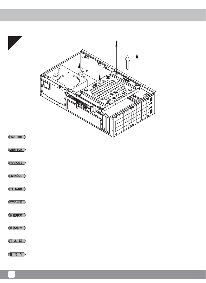
01
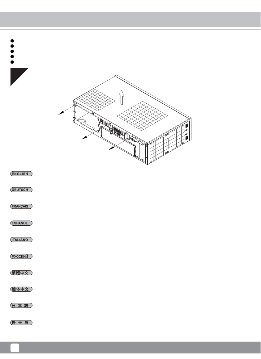
Unscrew three screws from the rear of the chassis then remove the top cover.
Lösen Sie die drei Schrauben von der Rückseite des Gehäuses, entfernen Sie dann die obere Abdeckung.
Dévissez les trois vis à l'arrière deboîtier et ensuite retirez le panneau supérieur.
Destornille los tres tornillos de la parte posterior del chasis y luego retire la cubierta superior.
Svitare le tre viti sul retro dello chassis per rimuovere il cover superiore.
Отвинтите три винта с задней части корпуса, затем снимите верхнюю крышку.
先用螺絲起子鬆開三顆螺絲,再取下上蓋板.
先用螺丝起子松开三颗螺丝,再取下上盖板.
ケースの 後ろからネジ3 本を 外し、それ から 上部 カバー を取り外し ます。
케이스 뒷편의 3개의 나사를 풀은뒤 상부 커버를 제거합니다.
3
Page 7
02
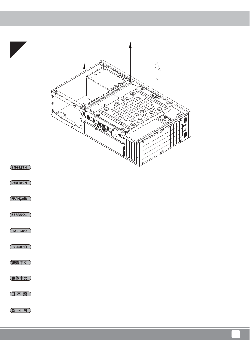
Unscrew two screws from the center brace to remove it.
Milo Series ML09
Installation Chart
Lösen Sie die beiden Schrauben von der mittleren Verstärkung, nehmen Sie sie heraus.
Dévissez les deux vis fixant la barre centrale pour la retirer.
Destornille los dos tornillos del soporte central para retirarlo.
Svitare le due viti dal sostegno centrale per rimuoverlo.
Отвинтите два винта с центральной скобы, чтобы снять ее.
鬆開中支架2顆螺絲,卸下中支架
松开中支架2颗螺丝,卸下中支架
センターブレースからネ ジ2本を外して、取り外しま す。
중심 브레이스에서 두개의 나사를 풀어 제거합니다.
4
Page 8
Milo Series ML09
Installation Chart
03
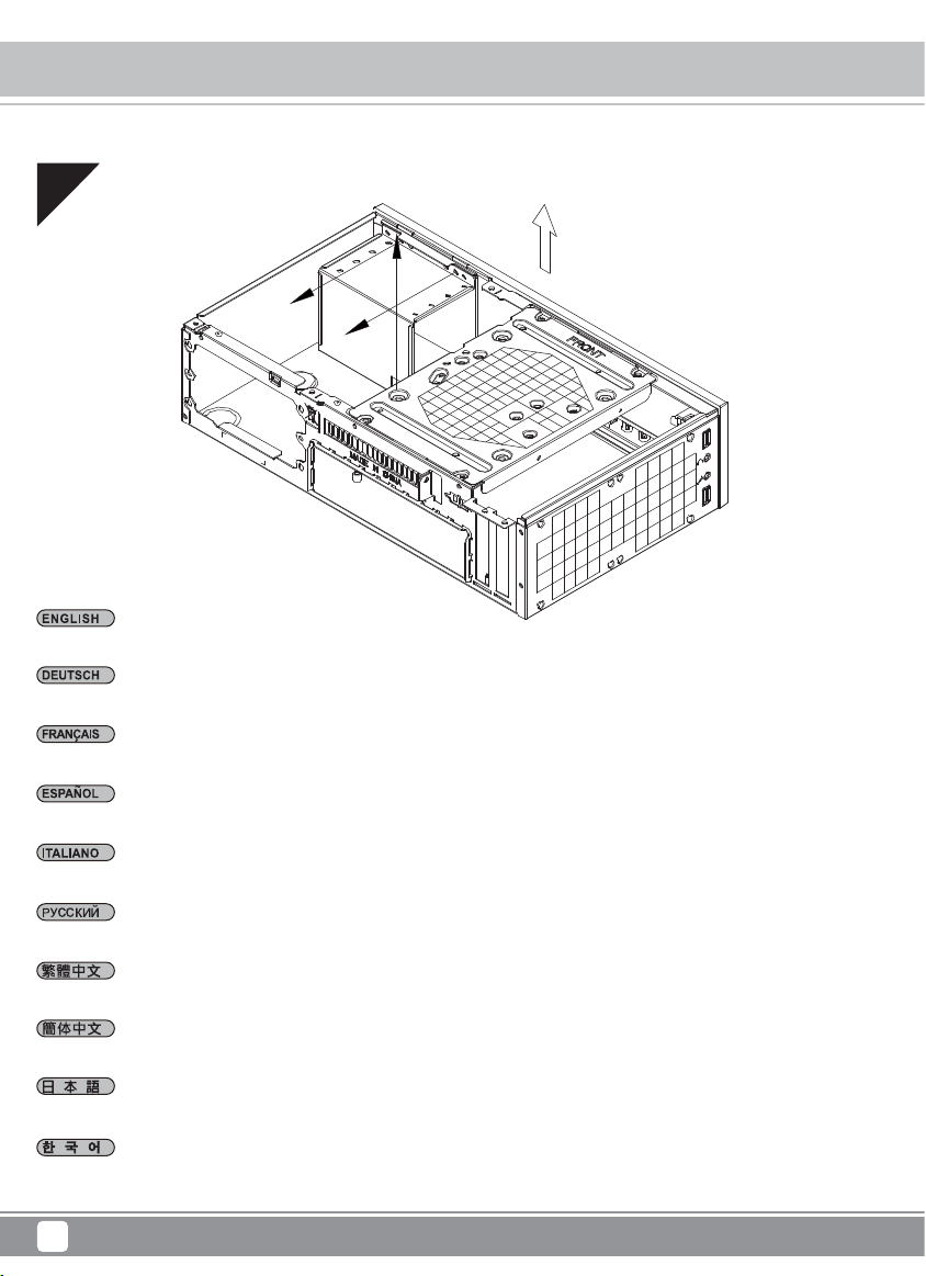
Unscrew screws from the hard drive bracket to remove it.
Lösen Sie die Schrauben der Festplattenhalterung, entfernen Sie sie.
Dévissez les vis du casier à disques durs pour le retirer.
Quite los tornillos del bracket del disco duro para retirarlo.
Svitare le viti del supporto hard drive per rimuoverlo.
Отвинтите винты с держателя жесткого диска, чтобы снять его.
鬆開硬碟架螺絲,卸下硬碟架
松开硬盘架螺丝,卸下硬盘架
ハードドライブブラケットのネジ を外して、取り外します。
하드 드라이브 브라켓을 제거하기 위해 나사를 제거합니다.
5
Page 9
Milo Series ML09
Installation Chart
04
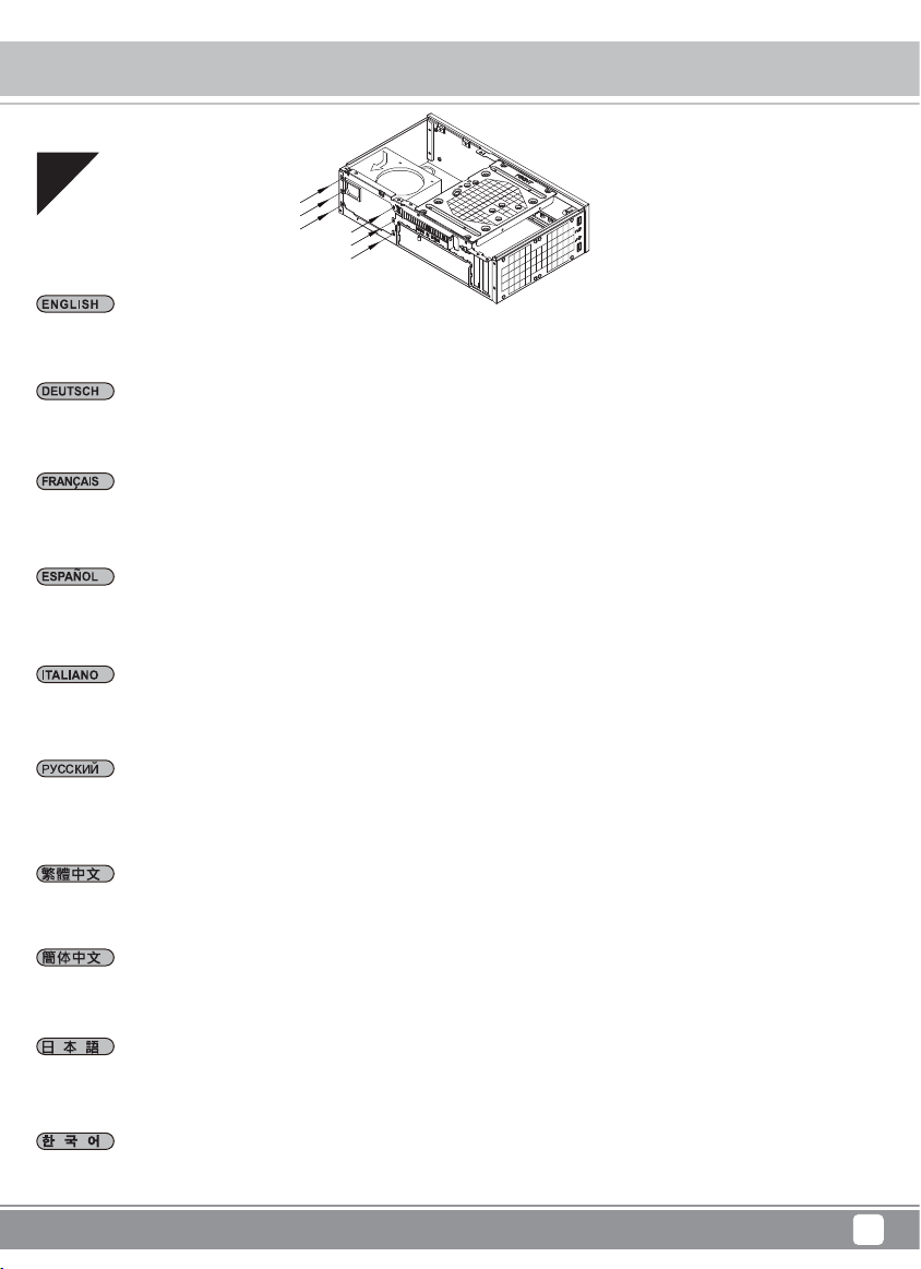
Install power supply into the case. Please note the case supports mounting power supply in two different orientations. If you use
SilverStone’s SFX power supply, you must install it with the 80mm fan facing up.
(For more information regarding power supply size limitations, please refer to the component guide in later pages)
Installieren Sie das Netzteil im Gehäuse. Bitte beachten Sie, dass das Gehäuse die Montage des Netzteils in zwei verschiedenen
Ausrichtungen unterstützt.
Wenn Sie SilverStones SFX-Netzteil verwenden, müssen Sie dieses mit dem 80-mm-Lüfter nach oben installieren.
(Weitere Informationen zur Beschränkung der Netzteilgröße entnehmen Sie bitte der Komponentenanleitung weiter hinten)
Installez l'alimentation dans le boîtier. Veuillez noter que le boîtier permet le montage des alimentations dans les deux sens.Si vous
utilisez une source d'alimentation SIlverStone SFX, vous devez l'installer avec le ventilateur de 80 mm face vers le haut.
(Pour plus d'informations sur les limitations des tailles des alimentations, veuillez-vous référer au guide des composant dans les
pages à venir)
Instale la fuente de alimentación en la carcasa. Por favor, tenga en cuenta que la carcasa monta la fuentes de alimentación orientada
de dos modos distintos. Si usa la fuente de alimentación SFX de SilverStone, deberá instalarla con el ventilador de 80mm hacia arriba.
(Para más información sobre las limitaciones de tamaño de la fuente de alimentación, consulte por favor la guía de componentes en
páginas posteriores).
Installare l’alimentatore nel case. L’alimentatore può essere orientato in due modi differenti.Se si usa l’alimentatore SFX SilverStone,
è necessario installarlo con la ventola da 80 mm rivolta verso l'alto.
(per maggiori informazioni in merito alle limitazioni di misura degli alimentatori, fate riferimento a quanto esposto nelle pagine successive)
Установите источник питания в корпус. Обратите внимание, что можно установить источник питания в двух разных
направлениях.При использовании блока питания SilverStone SFX 80mm вентилятор охлаждения следует установить лицевой
стороной вверх.
(для получения дополнительной информации относительно ограничений размера источников питания см. руководство к
компонентам далее).
安裝電源供應器,請注意此機殼的正反裝設計, 如果使用銀欣的SFX電源,8cm風扇請朝上(關於電源供應器長度規格,請參考元件尺寸限制)
安装电源供应器,请注意此机箱的正反装设计, 如果使用银欣的SFX电源,8cm风扇请朝上(关于电源供应器长度规格,请参考组件尺寸限制)
ケースに 電源 をインストールします。ケースは2つの異なる方向での電源設置をサポートしていることにご注意ください。SilverStone製SFX
電源を使用される場合、80mmファンを上向きに装着してください。
(電源サイズ制限の詳細については、後のページに記載 のコンポーネントガイドをご参照ください。)
파워 서플라이를 케이스에 설치합니다. 이 케이스는 파워 서플라이를 두개의 방향을 설치 가능합니다. SilverStone의 SFX 전원
공급장치를 설치할 경우, 80mm 팬이 위를 향하도록 하여 전원 공급장치를 설치해야 합니다.
(만약 파워 서플라이의 크기 및 제한에 대한 자세한 정보를 확인하려면, 뒤에 나오는 부품 가이드를 참조 바랍니다. )
6
Page 10
Milo Series ML09
Installation Chart
05
Remove the multipurpose bracket.
Nehmen Sie die Mehrzweckhalterung heraus.
Retirez le crochet multifonction.
Retire el bracket multipropósito.
Rimuovere la staffa multiuso.
Снимите мно гоцелево й кронштейн.
拆卸多功能磁架
拆卸多功能磁架
多目的ブラケットを取り外します。
다목적 브래 킷을 분리합니다.
7
Page 11
06
Insert the I/O shield included with your motherboard then install the motherboard into the case.
Milo Series ML09
Installation Chart
Bringen Sie die bei Ihrem Motherboard mitgelieferte Anschlussblende an, installieren Sie dann das Motherboard im Gehäuse.
Insérez la plaque des ports E/S inclus avec votre carte mère, puis mettez la carte mère dans le boîtier.
Inserte el escudo de E/S incluido con su placa base, luego instale la placa base en la carcasa.
Installate il pannello I/O della scheda madre, quindi la scheda madre stessa.
Установите панель ввода/вывода материнской платы, затем установите материнскую плату в корпус.
塞入I / O彈片,裝入主機板
塞入I/O弹片,装入主机板
マザーボードに付属のI/Oシールドを装着してから、ケース内にマザーボードを取り付けます。
메인보드와 동봉된 I/O 커버를 삽입한 후, 메인보드를 케이스에 설치합니다.
8
Page 12

Milo Series ML09
Installation Chart
07
We recommend at this point to plan for cable routing before connecting them to the motherboard, fan cables, 24pin cable, CPU ATX
4pin/EPS12V 8pin, front I/O connectors, and USB 3.0 connector.
Bereits ab diesem Schritt sollten Sie sich Gedanken über eine saubere Kabelführung machen, bevor Sie Anschlüsse am Motherboard
vornehmen; beachten Sie sämtliche Kabelanschlüsse (Lüfterkabel, 24-poliges Netzteilkabel, CPU-Kabel (4-polig, ATX / 8-polig, EPS12V),
Anschlüsse der Frondblende, E/A-Frontanschlüsse).
Nous vous recommandons de commencer dés à présent à réfléchir au routage des câbles avant de les branchez à la carte mère, câbles
incluant les câbles de ventilateurs, le câble 24 pin de l'alimentation, le connecteur de processeur ATX 4pin/EPS12V 8pin, les connecteurs
du panneau frontal, et les ports d'E/S.
Llegados a este punto le recomendamos que empiece a pensar sobre enrutar los cables de un modo limpio antes de conectarlos a
la placa base. Los cables incluyen los de los ventiladores, el de 24 pines de la fuente de alimentación, el de la CPU 4 pines ATX/8 pines
EPS 12V, los conectores del panel frontal y los conectores frontales de E/S.
A questo punto vi raccomandiamo di iniziare a pensare a come sistemare I cavi dell’alimentatore prima di connetterli alla scheda madre.
Nello specifico i cavi delle ventole, il connettore a 24pin, il connettore ATX 4pin/EPS12V 8pin, I connettori del pannello frontale e quelli
I/O sempre frontali.
На этом шаге рекомендуется продумать, как будут проложены кабели до их подсоединения к материнской плате: кабели
вентилятора, 24-контактный кабель источника питания, 4-контактный кабель ЦП ATX/8-контактный EPS 12 В, разъемы на
передней панели и передние разъемы ввода/вывода.
我們建議你在安裝主機板之前即開始準備整線動作。包含風扇電源線, PSU 24Pin接線 , CPU ATX 4Pin/EPS 8Pin接線,FrontPanel
Connectors與Front I/O Connectors。
我们建议你在安装主机板之前即开始准备整线动作。包含风扇电源线, PSU 24Pin接线 , CPU ATX 4Pin/EPS 8Pin接线,FrontPanel
Connectors与Front I/O Connectors。
この時点でマザーボード、ファンケ ー ブル、電源24ピンケーブル、CPUATX4ピン/EPS12V8ピン、フロントパネルコネクタ、およびフロント
I/Oコネクタと接続する前にケーブル取り回しをすっきりさせることを考慮し始めるようお勧めします。
이 시점에서 메인보드에 케이블 연결을 어떻게 해야 할지 잘 고려해 봐야 합니다. 케이블은 팬 케이블, 파워 서플라이 24핀 케이블,
CPU ATX 4Pin/EPS12V 8V 핀, 전면 패널 커넥터 및 전면 I/O 커넥터 등입니다.
9
Page 13

Milo Series ML09
Installation Chart
08
2
1
3
3
Depending on your requirements, install a slot-loading slim optical drive, 3.5” drive, or 2.5” drive onto the multipurpose bracket.
If additional cooling is not needed, the fan can also be removed.
(For 9.5mm slim optical drive install, stick on washer is needed and its front bezel replaced with included one from the ML09)
Installieren Sie je nach Anforderungen ein schmales optisches Slot-In-Laufwerk, ein 3,5-Zoll-Laufwerk oder ein 2,5-Zoll-Laufwerk
in der Mehrzweckhalterung. Falls keine zusätzliche Kühlung erforderlich ist, kann der Lüfter auch entfernt werden.
(Zur Installation eines 9,5 mm großen schlanken optischen Laufwerks wird die haftende Unterlegscheibe benötigt und die Frontblende
muss durch die beim ML09 mitgelieferte Blende ausgetauscht werden)
Selon vos besoins, installez un lecteur optique plat à chargement par fente , un lecteur de 3,5" ou un lecteur de 2,5" sur le support
multifonction. Si aucun refroidissement supplémentaire n'est nécessaire, le ventilateur peut également être enlevé.
(Pour l'installation du lecteur optique slim (fin) de 9,5 mm, il est nécessaire de mettre de la colle sur la rondelle et de remplacer son
cadre avant par un autre inclus avec le ML09)
Dependiendo de sus necesidades, instale un dispositivo óptico delgado de carga mediante ranura, dispositivo de 3,5” o dispositivo
de 2,5” en el bracket multipropósito. Si no se necesita refrigeración adicional, también podría retirarse el ventilador.
(Para instalar un dispositivo óptico delgado de 9,5mm hay que reemplazar las arandelas adhesivas y el bisel frontal con los incluidos
en la ML09)
In base alle necessità, installare sulla staffa multiuso un'unità ottica slim con fessura di caricamento, un'unità da 3,5”, o un'unità da 2,5”.
Se non è necessario ulteriore raffreddamento, la ventola può anche essere rimossa.
(Per l'installazione del drive ottico sottile da 9,5 mm, occorre il distanziatore a rondelle e sostituire il frontalino con quello incluso da ML09)
В зависимости от требований установите на универсальный кронштейн тонкий оптический привод с щелевой загрузкой,
3,5- или 2,5-дюймовый жесткий диск. Если дополнительное охлаждение не требуется, вентилятор можно снять.
(Для установки оптического привода толщиной 9,5 мм необходимо наклеить шайбу и заменить переднюю панель)
視需求安裝薄型光碟機、3.5吋或2.5吋硬碟至多功能磁架。若無額外散熱考量,風扇也可移除。
(9.5mm光碟機需要先更換光碟機面板與黏貼墊片)
视需求安装薄型光驱、3.5吋或2.5吋硬盘至多功能磁架。若无额外散热考虑,风扇也可移除。
(9.5mm光驱需要先更换光驱面板与黏贴垫片)
必要に応じて、スロットロー ディングスリム光 学ドライブ、3.5”ドライブ、または2.5”ドライブを多目的ブラケットに装着します。また、冷却を
特に必要としない場合は、ファンを取り外すことも可能です。
(9.5mmスリム光学ドライブ取り付けには、ワッシャ ーの 貼 付 、ならびにフロントベゼルのML09付属品への交換が必要となります。)
사용자의 요구사항에 따라, 슬롯 로딩 방식의 슬림형 광학 드라이브, 3.5” 드라이브 또는 2.5” 드라이브를 다목적 브래킷에 설치하십시오.
추가 냉각이 필요하지 않은 경우, 팬을 제거할 수도 있습니다.
(9.5mm 슬림형 광 드라이브가 설치된 경우, 와셔 부착이 필요하고 전면 베젤을 제공된 ML09 베젤로 교체해야 합니다.)
10
Page 14

Milo Series ML09
Installation Chart
09
Please remove optical drive cover before installing optical drive.
Bitte entfernen Sie die ODD-Abdeckung vor Installation des optischen Laufwerks.
Veuillez retirer le cache pour lecteur optique avant d'installer le lecteur optique.
Por favor, quite la tapa del dispositivo óptico antes de instalar el dispositivo óptico.
Rimuovere il coperchio dell'unità ottica prima di installare l'unità ottica.
Пожалуйста, снимите крышку отсека перед установкой оптического привода.
如果有安裝光碟機請移除前方大檔板。
如果有安装光驱请移除前方大檔板。
光学ドライブ取り付けの前に、光学ドライブ のカ バ ーを 取り外します。
광 드라이브 슬롯 커버를 제거하고 광 드라이브를 설치하십시오.
11
Page 15

Milo Series ML09
Installation Chart
10
Please insert the drive cage into the case at an angle so the optical drive can line up with the front panel, then secure with
screws.
Bitte stecken Sie den Laufwerkkäfig angewinkelt in das Gehäuse, damit das optische Laufwerk an der Frontblende ausgerichtet
werden kann; anschließend mit Schrauben befestigen.
Veuillez insérer la cage du lecteur dans le boîtier avec un angle permettant au lecteur optique de s'aligner avec le panneau avant,
puis fixez-la avec des vis.
Por favor, inserte la carcasa para dispositivos en la carcasa en ángulo de modo que el dispositivo óptico se alinee con el panel
frontal, luego fíjela con los tornillos.
Inserire la gabbia dell'unità nel case ad un angolo in cui l'unità ottica sia allineata con il pannello anteriore, quindi fissare le viti.
Пожалуйста, вставьте оптический привод в отсек корпуса так, чтобы он сравнялся с передней панелью корпуса, затем закрепите
привод шурупами.
光碟機需要深入前面板,請把磁架斜著放入機身再鎖固。
光驱需要深入前面板,请把磁架斜着放入机身再锁固。
光学ドライブがフロントパネ ルと同じ面に並 ぶよう角度を調節して、ドライブケージをケースに装着してから、ネジで固定します。
광 드라이브가 전면 패널과 일렬이 되도록 각도를 맞춰 드라이브 케이지를 케이스에 삽입하십시오.
12
Page 16

Milo Series ML09
Installation Chart
11
Remove 2.5” drive cage and install 2.5” hard drives into the drive cage.
Nehmen Sie die 2,5 Zoll-Laufwerkhalterung heraus. Bauen Sie 2,5-Zoll-Festplatten in die Laufwerkhalterung ein.
Retirez le casier des lecteurs 2.5”. Installez les disques durs 2.5”dans le casier.
Quite la carcasa para dispositivos de 2,5”. Instale discos duros de 2,5” en la carcasa para dispositivos.
Rimuovere il supporto hard drive da 2,5”. Installare gli hard drive da 2,5” nel supporto.
Извлеките кронштейн для 2,5-дюймовых жестких дисков. Установите 2,5-дюймовые жесткие диски в кронштейн для
жестких дисков.
安裝2.5”硬碟到2.5”硬碟架上,安裝2.5”硬碟架。
安装2.5”硬盘到2.5”硬盘架上,安装2.5”硬盘架。
2. 5 インチドライブケ ージ を取り外します。ドライブケージ に2.5インチ ハードドライブを装着します。
2.5” 드라이브 케이지를 제거합니다. 2.5” 하드 드라이브를 드라이브 케이지에 설치합니다.
13
Page 17

12
Install and secure required expansion cards.
Installieren und befestigen Sie die erforderlichen Erweiterungskarten.
Milo Series ML09
Installation Chart
Installez et fixez les cartes d'extension requises.
Instale y fije las tarjetas de expansión necesarias.
Installare ed assicurare le schede di espansione necessarie.
Установите и за крепите необходимые платы расширения.
移除介面卡檔片,安裝介面卡。
移除适配卡档片,安装适配卡。
必要とされる 拡張カードをインストールし、固定します。
필요한 확장카드를 설치하고 고정시킵니다.
14
Page 18

Milo Series ML09
Installation Chart
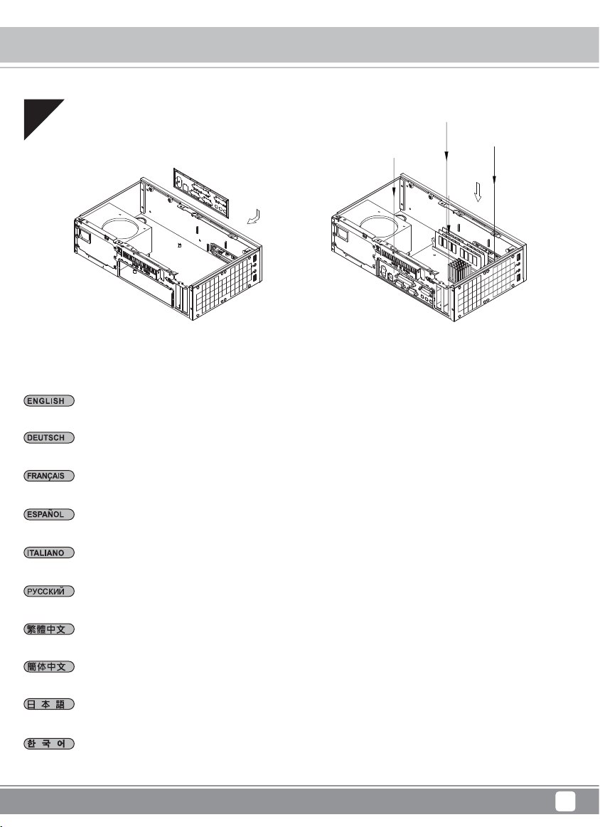
13
Reinstall center brace back into the case.
Bringen Sie die mittlere Verstärkung wieder im Gehäuse an.
Réinstallez la barre centrale dans le boîtier.
Reinstale el soporte central en la carcasa.
Reinstallare il sostegno centrale nel case.
Установите ц ен тральную скобу обратно в корпус.
將中支架裝回機殼。
将中支架装回机箱。
ケースにセンターブレースを戻します。
중심 브 레이스를 케이스에 재 설치합니다.
15
Page 19

Milo Series ML09
Installation Chart
14
Place the top cover back onto the case and secure with three screws to complete installation.
Platzieren Sie die obere Abdeckung auf dem Gehäuse und befestigen Sie sie zum Abschluss der Installation mit drei Schrauben.
Remettez le panneau supérieur sur le boîtier et fixez le avec trois vis pour terminer l'installation.
Vuelva a poner la cubierta superior en la carcasa y fíjela con tres tornillos para completar la instalación.
Riposizionare quindi il cover superiore ed assicurarlo allo chassis con le tre viti rimosse in precedenza per completare l’installazione.
Завершите установку, установив верхнюю крышку обратно на корпус и закрепив тремя винтами.
將上蓋裝回機殼,完成組裝。
将上盖装回机箱,完成组装。
ケースに上部カバーを戻し、3つのネジ3本で固定すると、インストールは完成です。
상부 커버를 케이스에 재 장착후 3개의 나사로 고정시켜 설치를 마칩니다.
16
Page 20

Milo Series ML09
Installation Chart
15
Depending on requirement or preference, use rubber feet for horizontal orientation or stand for vertical orientation.
Je nach Anforderungen oder Vorlieben können Sie die Gummifüße zur horizontalen Anordnung nutzen oder zur vertikalen Aufstellung
aufrichten.
Selon le besoin ou la préférence, utilisez des pieds en caoutchouc pour une orientation horizontale ou le support pour une orientation
verticale.
Dependiendo de los requisitos o preferencias, use pies de goma para una orientación horizontal o una plataforma para una
orientación vertical.
In base ai requisiti o alle preferenze, utilizzare i piedini in gomma per l'orientamento orizzontale oppure il supporto per l'orientamento
verticale.
В зависимости от ваших требований или предпочтений установите резиновые опоры для использования в горизонтальном
положении или вертикальную стойку для использования в вертикальном положении.
視需求或喜好選擇使用直立式或平放式腳墊。
视需求或喜好选择使用直立式或平放式脚垫。
必要やお好みに応じて、横置きや縦置きに合わせてゴム製フィートを取り付けます。
요구사항 또는 취향에 따라, 수평 방향의 경우 고무 받침대를 사용하거나 수직 방향의 경우 스탠드를 사용하십시오.
17
Page 21

Milo Series ML09
Connector definition
(1) Fort panel connector installation
Power switch and reset switch installation guide:
Please refer to the motherboard manuals for the motherboard’s “Front Panel Connector” or “System Panel Connector” pin definition.
Power switch and reset switch have no polarity, so they can be connected in any orientation.
Ein-/Ausschalter und Rücksetztaste (Reset) installieren:
Bitte suchen Sie in der Motherboard-Dokumentation nach der Pinbelegung der Anschlüsse des Frontbedienfeldes („Front Panel Connectors“
oder „System Panel Connectors“). Ein-/Austaste und Rücksetztaste benötigen keine bestimmte Polarität, können daher beliebig (ohne auf +
und - zu achten) angeschlossen werden.
Guide d'installation des interrupteurs d'allumage et de réinitialisation :
Veuillez-vous référer au manuel de votre carte mère pour la description des broches "des connecteurs du panneau frontal" et des broches "des
connecteurs du panneau système". Les interrupteurs d'allumage et de réinitialisation ne possède pas de polarité, donc ils peuvent être branché
dans les deux sens.
Guía de instalación de los interruptores de encendido y reseteo:
Por favor, consulte en los manuales de la placa base la configuración de pines del “Conector de panel frontal” ó “Conector de panel de sistema”
de su placa base. Los interruptores de encendido y reseteo no tienen polaridad, luego se pueden conectar con cualquier orientación.
Guida all’installazione dei connettori Power Switch e Reset Switch:
Fare riferimento al manuale della scheda madre nella sezione “Connettori del pannello frontale” o “Connettori del pannello di sistema”.
Power switch e reset switch non hanno polarità, posso essere pertanto connessi con qualsiasi orientamento.
Инструкция по подключению выключателя питания и кнопки перезагрузки (reset):
Описание контактов разъемов приведены в разделах “Разъем ы передней панели” или “Разъем ы системной панели” руководства
пользователя материнской платы. Выключатель питания и кнопка перезагрузки не имеют полярности, поэтому их можно подключать
любой ориентации.
в
Power Switch 與Reset Switch安裝說明:
請參考主機說明書的Front Panel Connectors安裝Pin Define,將Connector插上;Power Switch 與Reset Switch並無正負極性之分,
反插正插都不影響功能性。
Power Switch 与Reset Switch安装说明:
请参考主机说明书的Front Panel Connectors 安装Pin Define,将Connector插上;Power Switch与Reset Switch并无正负极性之分,
反插正插都不影响功能性。
電源スイッチおよびリセットスイッチのインストールガイド:
マザーボードの「フロントパネルコネクタ」または「システムパネルコネクタ」のピン配列についてはマザーボードマニュアルを参照
してください。電源スイッチとリセットスイッチに極性はないので、いずれの方向でも接続できま。
파워 스위치 및 리셋 스위치 설치 가이드
메인보드 매뉴얼의 전면패널 커넥터 혹은 시스템패널 커넥터 핀을 참조하기 바랍니다. 파워 스위치와 리셋 스위치는 극성이 없어
어떤 방향으로 설치해도 무방합니다.
18
Page 22

Milo Series ML09
Connector definition
Please refer to the motherboard manuals for the motherboard’s “Front Panel Connector ” or “System Panel Connector” pin definition.;
the white/black wires are negative while other colors are positive wires. The Power LED wires are separate pins for compatibility with different
motherboard so please make sure they are connected in the right polarity by referring to your motherboard manual.
Bitte suchen Sie in der Motherboard-Dokumentation nach der Pinbelegung der Anschlüsse des Frontbedienfeldes („Front Panel Connectors“ oder „
System Panel Connectors“). Die weißen/ schwarz Adern sind negativ (-), die farbigen Adern positiv (+).Die Kabel für die Betriebsanzeige-LED
sind zur Kompatibilität mit unterschiedlichsten Motherboards einzeln, nicht als kompletter Stecker ausgeführt. Achten Sie hier bitte auf die richtige
Polarität, lesen Sie in der Dokumentation Ihres Motherboards nach.
Veuillez-vous référer au manuel de votre carte mère pour la description des broches "des connecteurs du panneau frontal" et des broches "des
connecteurs du panneau système". Les câbles colorés en blanc/noir sont négatifs alors que ceux d'une autre couleur sont positifs. Les câbles de
la LED Power sont séparés afin d'être compatible avec différentes cartes mères, donc vérifiez bien qu'ils sont branchés avec la bonne polarité en
vous référant au manuel de votre carte mère
Por favor, consulte en los manuales de la placa base la configuración de pines del “Conector de panel frontal” ó “Conector de panel de sistema”
de su placa base. Los cables de color blanco/negro son negativos mientras que los de color son positivos. Los cables LED de potencia tienen
pines separados para compatibilidad con diferentes definiciones de pines de la placa base luego por favor, asegúrese de que están conectados
en la polaridad correcta consultando el manual de su placa base.
Fare riferimento al manuale della scheda madre nella sezione “Connettori del pannello frontale” o “Connettori del pannello di sistema”. I cavi di
colore bianco/nero sono il polo negativo, mentre quelli di colore diverso il positivo.
Описание контактов разъемов приведены в разделах “Разъемы передней панели” или “Разъемы системной панели” руководства
пользователя материнской платы. Белые/черный провода - отрицательной полярности, цветные провода - положительной полярности.
Провода светодиодного индикатора питания имеют отдельные контакты для совместимости с
плат, поэтому обратитесь к руководству пользователя материнской платы и убедитесь, что полярность соблюдена.
請參考主機說明書的Front Panel Connectors安裝Pin Define,將Connector插上; 白/黑色線的部分為負極,彩色線的部分是正極。Power LED為
了適應各主機板的不同, 特別設計為散Pin樣式,請安心使用。
:
различными типами контактов материнских
请参考说明书的Front Panel Connectors安装Pin Define,将Connector插上;白/黑色线的部份为负极,彩色线的部份为正极。Power LED为了适应
主机板的不同, 特别设计为散Pin样式,请安心使用。
マザーボードの「フロントパネルコネクタ」または「システムパネルコネクタ」ピン配列についてはマザーボードマニュアルを参照してください。
白/黑色のリード線はマイナスで、色の着いたリード線がプラスです。電源LEDリード線は種々のマザーボードピン定義と互換性を持たせるため
分離されたピンとなっているので、ご使用のマザーボードマニュアルを参照して、適切な極性に接続されるようお確かめください。
메인보드 매뉴얼의 전면패널 커넥터 혹은 시스템패널 커넥터 핀을 참조하기 바랍니다. 하얀/검은선의 경우 음극이며, 다른 색의 경우
양극입니다. 파워 LED 선은 분리되어 다양한 메인보드에서 동작할 수 있도록 되어 있습니다. 그러므로 메인보드 매뉴얼을 참조하여 올바를
극성을 주의해 선택하시기 바랍니다.
19
Page 23

Milo Series ML09
Connector definition
(2) Front I/O connector guide
Below are the front I/O connectors pin definition, please also check your motherboard manual to cross reference with motherboard’s
front I/O pin headers. SilverStone’s I/O connectors are in block type to simplify installation.
Nachstehend finden Sie die Pinbelegung der vorderen E/A-Anschlüsse; bitte gleichen Sie zudem das Handbuch Ihres Motherboards mit
den vorderen E/A-Pinzuweisungen ab. SilverStones E/A-Anschlüsse befinden sich zur Vereinfachung der Installation in Blockart.
Au dessous de la description des broches des ports d'E/S, veuillez aussi vérifier sur le manuel de votre carte mère de manière croisée
que les broches sont correctement placées. Les connecteurs d'E/S de SilverStone sont en bloc pour en simplifier leur installation.
A continuación se detallan los pines para conectores E/S frontales, compruebe también por favor el manual de su placa base para
cotejar los pines E/S frontales de la misma. Los conectores E/S de SilverStone son del tipo bloque para simplificar la instalación.
Di seguito lo schema delle connessioni I/O frontali, confrontare lo schema con quanto riportato sul manuale della scheda madre per
effettuare un controllo incrociato. I connettori I/O Silverstone, per semplificare l’installazione, sono del tipo “a blocco”.
Ниже приведено описание контактов передних разъемов ввода/вывода. Обратитесь также к руководству пользователя материнской
платы за описанием передних разъемов ввода/вывода типа "пин-хедер". Разъемы ввода/вывода "SilverStone" - блочного типа, что
облегчает сборку.
下表為Front I/O Connectors的Pin Define,請參閱主機板說明書的各Front I/O Connectors Pin Define一一核對。
ML09的Front I/O Connectors完全採用集合
下表为Front I/O Connectors的Pin Define,请参阅主机板说明书的各Front I/O Connectors Pin Define一一核对。
ML09的Front I/O Connectors完全采用集合Pin方式以简化安装。
以下はフロントI/Oコネクタピン配列ですが、お持ちのマザーボードのフロントI/Oピンヘッダは、マザーボードマニュアルをご参照
ください。シルバーストーンのI/Oコネクタは、インストールの容易なブロックタイプになっています。
아래는 전면 I/O 커넥터의 핀 사양입니다. 메인보드 매뉴얼을 참조해, 메인보드의 전면 I/O 핀사양을 재 확인한 후 설치합니다.
SilverStone의 I/O 커넥터는 블록 타입으로 구성되어 있어 간편한 설치가 가능합니다.
Pin方式以簡化安裝。
USB 3.0 CONNECTOR HD CONNECTOR
Pin 1
Vbus
IntA_P1_SSRX-
IntA_P1_SSRX+
GND
IntA_P1_SSTX-
IntA_P1_SSTX+
GND
IntA_P1_D-
IntA_P1_D+
ID
Pin 19
Vbus
IntA_P2_SSRXIntA_P2_SSRX+
GND
IntA_P2_SSTXIntA_P2_SSTX+
GND
IntA_P2_DIntA_P2_D+
Pin 11Pin 10
20
Page 24

Milo Series ML09
Component size limitations
The ML09 was designed to be as small as possible while maximizing interior space usage, please refer to the
:
following guidelines forcomponent selection and future upgrade considerations.
(1) CPU cooler height limitation
CPU Cooler height limitation will vary depending on the component installed on the multipurpose bracket. Please refer to the table below.
Die maximale Höhe des CPU-Kühlers hängt davon ab, welche Komponenten in der Mehrzweckhalterung installiert wurden. Bitte
orientieren Sie sich an der folgenden Tabelle.
La limite de la hauteur du refroidisseur de CPU varie en fonction du composant installé sur le crochet multifonction. Veuillez vous
reporter au tableau ci-dessous.
La limitación de altura del disipador para la CPU variará dependiendo de los componentes instalados en el bracket multipropósito.
Por favor consulte la tabla siguiente.
La limitazione dell’altezza del dispersore di calore CPU varierà in base ai componenti installati sulla staffa multiuso. Fare riferimento
alla tavola che segue.
Отвинтите три винта с задней части корпуса, затем снимите верхнюю крышку.
CPU 散熱器限高會依據多功能磁架的安裝的裝置不同而有所差異。請參考下表。
CPU 散热器限高会依据多功能磁架的安装的装置不同而有所差异。请参考下表。
CPUクーラー高さ限界は多目的ブラケットに装着されたコンポーネントに依存します。下表をご参照ください。
확장 슬롯 커버를 제거하고 필요한 그래픽 카드나 확장 카드를 설치하십시오.
Motherboard
70
COOLER
Motherboard
55
2.5” HDD
COOLER
Component installed
Bracket removed
Motherboard
50
COOLER
12015 FAN
Motherboard
37
COOLER
12025 FAN
2.5” drive, 9.5mm thick
Slim optical drive
3.5” drive/120mm x 25mm fan
Motherboard
SLIM ODD
50
COOLER
37 3.5” HDD
Motherboard
COOLER
21
Cooler limitation
70mm
55mm
50mm
37mm
Page 25

Milo Series ML09
Component size limitations
Illustration showing actual position of 3.5” drive and 120mm fan on the bracket.
Due to thickness of a 120mm x 25mm fan and 3.5”drive, the illustration shows their relative positions over the motherboard for reference.
If they overhang a USB 3.0 header on the motherboard, it could prevent the installation of USB 3.0 cable.
Abbildung zeigt tatsächliche Position von 3,5-Zoll-Laufwerk und 120-mm-Lüfter an der Halterung.
Aufgrund der Dicke von einem Lüfter mit den Maßen 120 mm x 25 mm und einem 3,5-Zoll-Laufwerk zeigt die Abbildung ihre
relativen Positionen über dem Motherboard zur Veranschaulichung. Falls sie eine USB 3.0-Stiftleiste am Motherboard verdecken,
kann möglicherweise kein USB 3.0-Kabel angeschlossen werden.
Illustration indiquant la position réelle du lecteur 3,5" et du ventilateur de 120 mm sur le support.
En raison de l'épaisseur d'un ventilateur de 120 mm x 25 mm et d'un lecteur de 3,5", l'illustration montre leurs positions relatives
sur la carte mère pour référence. S'ils surplombent un connecteur USB 3.0 sur la carte mère, cela peut empêcher l'installation du
câble USB 3.0.
La ilustración muestra la posición real de un dispositivo de 3,5” y ventilador de 120mm en el bracket.
Debido al grosor de un ventilador de 120mm x 25mm y un dispositivo de 3,5”, la ilustración muestra sus posiciones relativas sobre
la placa base como referencia. Si un conector USB 3.0 sobresale sobre la placa base, podría impedir instalar un cable USB 3.0
L’illustrazione mostra la posizione attuale dell’unità da 3,5" e della ventola da 120 mm sulla staffa.
A causa dello spessore di una ventola da 120 mm x 25 mm e dell’unità da 3,5", la figura mostra le posizioni relative sulla scheda madre
come riferimento. Se sporgono da un collettore USB 3.0 sulla scheda madre, potrebbero impedire l'installazione del cavo USB 3.0.
На рисунке показано размещение на универсальном кронштейне 3,5-дюймового диска и 120-мм вентилятора.
На рисунке показано относительное расположение вентилятора с размерами 120 x 25 мм и 3,5-дюймового диска над
системной платой. Их размещение над разъемом USB 3.0 на системной плате может помешать установке кабеля USB 3.0.
圖示為3.5吋硬碟與120mm風扇在多功能磁架上的實際安裝位置。
基於120mm x 25mm風扇與3.5吋硬碟裝置本身的厚度,主機板USB 3.0接頭可能會干涉導致無法安裝,圖示為磁架覆蓋主機板之實際位
置,供您參考。
图标为3.5吋硬盘与120mm风扇在多功能磁架上的实际安装位置。
基于120mm x 25mm风扇与3.5吋硬盘装置本身的厚度,主板USB 3.0接头可能会干涉导致无法安装,图示为磁架覆盖主板之实际位置,
供您参考。
ブラケットにおける3.5”ドライブおよび120mmファンの実際位置を示した図
図には、120mmx25mmファンおよび3.5”ドライブの厚さによる、マザーボードにおける位置が参考に示されています。それらがマザーボ
ードのUSB3.0ヘッダの上にかかる場合は、USB3.0ケーブルが接続できないことになります。
브래킷 상에서 3.5” 드라이브 및 120mm 팬의 실제 위치를 보여주는 그림.
120mm x 25mm 팬 및 3.5” 드라이브의 두께 때문에, 그림에서는 참조를 위해 마더보드 상의 상대적 위치를 표시합니다. USB 3.0
헤더가 마더보드 위에 걸린 경우, USB 3.0 케이블의 설치를 방해할 수 있습니다.
22
Page 26

Milo Series ML09
Component size limitations
(2) Power supply limitation
100
ML09 supports standard SFX power supply with up to 100m depth only.
Der ML09 unterstützt SFX-Standardnetzteile mit einer Tiefe von 100 mm.
Le ML09 supporte une source d'alimentation SFX standard avec une profondeur de 100mm.
La ML09 acepta fuentes de alimentación SFX estándar con una profundidad de 100mm.
ML09 supporta l’alimentatore standard SFX con una profondità di 100 mm.
Корпус ML09 совместим со стандартными блоками питания SFX глубиной 100 мм.
ML09限定使用長度為100mm的標準SFX電源。
ML09限定使用长度为100mm的标准SFX电源。
ML09は標準SFX電源(100㎜深)に対応しています。
ML09는 100mm 깊이의 표준 SFX 전원 공급장치를 지원합니다.
23
Page 27

Milo Series ML09
Component size limitations
(3) Expansion card limitation
190
ML09 can accommodate low profile cards up to 6.9”. Standard low profile cards are usually only 6.6” long so ML09 should fit nearly
any low-profile card on the market.
Das ML09 Low-Profile-Erweiterungskarten mit einer Länge von bis zu 17,52 cm aufnehmen. Standard-Low-Profile-Karten
sind üblicherweise nur 16,76 cm lang - dadurch passen nahezu alle Arten von Low-Profile-Karten in das ML09.
Le ML09 peut accueillir des carte d'extension low profile jusqu'à 6.9” de long. Les cartes low profile standard ont habituellement
une longueur de seulement 6.6” long donc le ML09 pourra accueillir tous les types de cartes low profile.
La ML09 puede acomodar tarjetas de expansión de perfil bajo de hasta 6,9” de longitud. Las tarjetas normales de perfil bajo suelen
tener solo 6,6” de longitud, luego la ML09 debería poder instalar cualquiera de estas tarjetas.
ML09 può alloggiare schede di espansione a basso profilo lunghe fino a 175,2mm. Le schede low profile standard sono generalmente
lunghe soltanto 167,6mm quindi, all’interno di ML09, possono essere installate quasi tutte le schede low profile.
ML09 можно установить платы расширения малых размеров длиной до 6,9 дюймов. Стандартные платы малого
размера обычно имеют длину 6,6 дюйма, поэтому ML09 должен поддерживать практически все типы плат малого
размера.
ML09 支援最長6.9”長的Low profile擴充卡。一般規範的Low profile擴充卡長度只有6.6”,所以任何的Low profile介面卡應當
都可以安裝。
ML09 支持最长6.9”长的Low profile扩展卡。一般规范的Low profile扩展卡长度只有6.6”,所以任何的Low profile适配卡应当
都可以安装。
ML09は長さ最大6.9インチのロープロファイル拡張カードを装着できます。標準のロープロファイル拡張カードは通常、長さ6.6インチに
過ぎないので、ML09にはほとんど全てのタイプのロープロファイルカードが搭載可能です。
ML09은 6.9”까지 LP 형태의 확장 카드를 지원합니다.일반적인 LP 카드의 경우 대부분 6.6” 의 길이를 갖고 있어 ML09 은 거의
대부분의 LP 카드 장착이 가능합니다.
24
Page 28

Milo Series ML09
Component size limitations
Thickness limits
There is 50mm of room for expansion card slot in terms of thickness. If 80mm x 15mm fans are installed on the side panel, a dual
slot card can still be used. However, with 80mm x 25mm fans installed, there will only be enough room for a single slot card.
Hinsichtlich der Dicke haben Sie 50 mm Platz für einen Erweiterungskartensteckplatz. Auch wenn Lüfter mit den Maßen 80 mm x 15 mm
an der Seitenblende installiert werden, kann dennoch eine Karte eingebaut werden, die zwei Steckplätze erfordert. Werden jedoch
Lüfter mit den Maßen 80 mm x 25 mm installiert, reicht der Platz nur für eine Karte, die lediglich einen Steckplatz benötigt.
Il y a 50 mm d'espace pour la fente de carte d'extension en termes d'épaisseur. Si des ventilateurs de 80 mm x 15 mm sont installés
sur le panneau latéral, on peut toujours utiliser une carte sur deux fentes. Cependant, avec des ventilateurs de 80 mm x 25 mm
installés, il n'y a assez de place que pour une carte d'une seule fente.
Hay 50mm de espacio para zócalos de tarjetas de expansión respecto al grosor. Si se instalan ventiladores de 80mm x 15mm en el
panel lateral, todavía se puede usar una tarjeta de zócalo dual. Sin embargo, con los ventiladores de 80mm x 25mm instalados, solo
habrá espacio para una tarjeta de un único zócalo.
Ci sono 50 mm di spazio in termini di spessore per le schede di espansione. Se sul pannello laterale sono installate ventole da
80 mm x 15 mm, può ancora essere utilizzata una scheda a alloggio doppio. Tuttavia, quando sono installate ventole da 80 mm x 25 mm,
ci sarà spazio solo per una scheda a alloggio singolo.
Для размещения карты расширения с учетом толщины предусмотрено пространство 50 мм. При установке вентиляторов с
размерами 80 x 15 мм на боковой панели можно использовать карту с двумя слотами. Однако при установке вентиляторов
с размерами 80 x 25 мм остается пространство для установки карты только с одним слотом.
擴充卡槽有50mm的總和厚度空間,如果安裝80mm x 15mm薄型風扇在側板,雙槽厚度顯卡可以正常安裝,若安裝80mm x 25mm風扇,則
僅能使用單槽擴充卡。
扩展卡槽有50mm的总和厚度空间,如果安装80mm x 15mm薄型风扇在侧板,双槽厚度显卡可以正常安装,若安装80mm x 25mm风扇,则
仅能使用单槽扩展卡。
拡張カードスロットの厚さに関しては50mmの余地があります。80mmx15mmファンが側面パネルに装着されても、デュアルスロットカ ー
ドは装着可能です。ただし、80mmx25mmファンが装着された場合、装着可能なのはシングルスロットカードのみとなります。
두께로 볼 때 확장 카드 슬롯을 위한 50mm의 공간이 있습니다. 측면 패널에 80mm x 15mm 팬이 설치된 경우 여전히 듀얼 슬롯
카드를 사용할 수 있습니다. 그러나 80mm x 25mm 팬을 설치하면, 싱글 슬롯 카드만 사용할 수 있는 공간만 남습니다.
25
Page 29

Milo Series ML9
26
라이브
의 경
로딩
Component size limitations
(4) Optical drive support
ML09 is compatible with only 12.7mm or 9.5mm slim optical drives. For 9.5mm slim optical drive, only tray-loading type can be used
and its installation requires replacing front bezel with one included with ML09 and application of stick on washer.
ML09 ist nur mit 12,7 oder 9,5 mm großen schlanken optischen Laufwerken kompatibel. Bei 9,5 mm großen schlanken
optischen Laufwerken können nur solche mit Schublade verwendet werden; außerdem muss zur Installation die Frontblende
durch die mit dem ML09 mitgelieferte Blende ersetzt werden und Sie benötigen die haftende Unterlegscheibe.
Le ML09 est uniquement compatible avec les lecteurs optiques fins de 12,7 mm ou 9,5 mm. Pour le lecteur optique fin de 9,5 mm,
seul le type chargement à plateau peut être utilisé et son installation nécessite le remplacement du cadre avant par un autre inclus
avec le ML09, ainsi que l'application de colle sur la rondelle.
ML09 è compatibile solo con le unità ottiche sottili da 12,7 mm o 9,5 mm. Per l'unità ottica sottile da 9,5 mm, è possibile utilizzare solo il
tipo a vassoio e la sua installazione necessita la sostituzione del frontalino con quello incluso con ML09 e l'applicazione del distanziatore
a rondelle.
Корпус ML09 совместим только с оптическими приводами толщиной 12,7 мм и 9,5 мм. Для установки привода
толщиной 9,5 мм требуется специальный лоток, установка которого требует замены передней панели
(есть в комплекте).
ML09只能使用12.7mm或9.5mm薄型光碟機。ML09使用9.5mm薄型光碟機只能使用Tray盤式,安裝我們所附的轉換檔板,
並在光碟機右邊黏貼墊片。
ML09只能使用12.7mm或9.5mm薄型光驱。ML09使用9.5mm薄型光驱只能使用Tray盘式,安装我们所附的转换文件板,
并在光驱右边黏贴垫片。
ML09は、12.7mmまたは9.5mmスリム型光学ドライブとのみ互換性を有しています。9.5mmスリム型光学ドライブの場合、
トレイローディング式のみ使用可能で、フロントベゼルのML09付属品への交換ならびにワッシャーへの貼付が必要となります。
12.7mm 또는 9.5mm 슬림형 광 드라이브만 ML09와 호환됩니다. 9.5mm 슬림형 광 드라이브의 경우 트레이 로딩 타입만 사용할 수
있으며 설치할 때 전면 베젤을 제공된 ML09로 교체하고 와셔를 부착해야 합니다.
9.5mm
12.7mm
26
Page 30

Milo Series ML09
Component size limitations
(5) Optimal thermal management
A 120mm x 15mm slim fan is pre-installed onto the multipurpose bracket from the factory for adequate cooling for most needs.
Compared to ML06, the ML09’s two 80mm fan slots are designed for cooling the graphics card as opposed to the CPU area. If
you plan on utilizing the multipurpose bracket for drives, the fan must be removed so please make sure that your CPU has low
enough power output to cope with less airflow.
Ein schmaler Lüfter mit den Maßen 120 mm x 15 mm ist zur angemessenen Kühlung für die meisten Anforderungen ab Werk an der
Mehrzweckhalterung vorinstalliert. Im Gegensatz zum ML06 sind die beiden 80-mm-Lüftersteckplätze des ML09 für die Kühlung der
Grafikkarte anstatt für die Kühlung des CPU-Bereichs vorgesehen. Falls Sie die Mehrzweckhalterung für Laufwerke nutzen möchten,
muss der Lüfter entfernt werden; achten Sie also bitte darauf, dass Ihre CPU eine ausreichend geringe Leistungsausgabe zur
Bewältigung eines geringeren Luftstroms besitzt.
Un ventilateur plat de 120 mm x 15 mm est préinstallé en usine sur le support multifonction pour un refroidissement couvrant la plupart
des besoins. Par rapport au ML06, les deux fentes de ventilateur de 80 mm du ML09 sont conçues pour le refroidissement de la carte
graphique, par opposition à la zone du processeur. Si vous prévoyez d'utiliser le support multifonction pour des lecteurs, le ventilateur
doit être enlevé, veuillez donc vous assurer que votre processeur a une puissance de sortie assez faible pour s'adapter à un flux d'air
moindre.
Se preinstala de fábrica un ventilador delgado de 120mm x 15mm en el bracket multipropósito para una refrigeración adecuada respect a
casi todas las necesidades. Comparada con la ML06, los dos zócalos para ventilador de 80mm de la ML09 están diseñados para refrigerar
las tarjetas gráficas frente a la zona de la CPU. Si planea utilizar el bracket multipropósito para discos, el ventilador debe retirarse, por tanto
asegúrese de que su CPU tiene suficiente potencia de salida como para compensar el menor flujo de aire.
In fabbrica è pre-installata sulla staffa multiuso una ventola slim da 120 mm x 15 mm per un raffreddamento adeguato per la maggior
parte delle esigenze. Rispetto a ML06, i due alloggi ventola da 80 mm di ML09 sono progettati per il raffreddamento della scheda
grafica invece che dell'area CPU. Se si intende utilizzare la staffa multiuso per le unità, la ventola deve essere rimossa, pertanto
assicurarsi che la CPU abbia sufficiente uscita a bassa potenza per far fronte al minor flusso d'aria.
Тонкий вентилятор с размерами 120 x 15 мм уже установлен в заводских условиях на универсальном кронштейне для
обеспечения нужного охлаждения в большинстве случаев. В отличие от корпуса ML06 два слота 80-мм вентиляторов
в корпусе ML09 предназначены для охлаждения графической карты вне зоны размещения процессора. Если вы
собираетесь использовать универсальный кронштейн для установки дисков, вентилятор придется убрать, поэтому
процессор с низким энергопотреблением должен быть рассчитан на меньший воздушный поток.
多功能磁架已預先安裝120mm x 15mm風扇,足以應付一般散熱需求。相對於舊版的ML06,ML09兩側80mm風扇槽設計只針對顯示卡區域
散熱,而非CPU區域。如果您需要在多功能磁架安裝硬碟或薄型光碟機,拆卸風扇前,請先確定您的CPU耗電量夠低,足以應付系統風
流的減少。
多功能磁架已预安装120mm x 15mm风扇,足以应付一般散热需求。相对于旧版的ML06,ML09两侧80mm风扇槽设计只针对显示卡区域散
热,而非CPU区域。如果您需要在多功能磁架安装硬盘或薄型光驱,拆卸风扇前,请先确定您的CPU耗电量够低,足以应付系统风流的
减少。
工場出荷時に120mmx15mmスリムファンが多目的ブラケットに予め装着されており、殆どのニーズに合わせた放熱性能を発揮します。
ML06と異なり、ML09には2つの80mmファンスロットが設計されており、CPUエリア以外のグラフィックスカード部分も冷却します。ドライ
ブ用に多目的ブラケットの使用を考慮される場合、ファンは取り外す必要があるので、より少ない放熱でも使用可能な、出力の小さいCPU
をお選びください。
120mm x 15mm 슬림형 팬은 대부분의 경우 적절한 냉각을 제공할 수 있도록 공장에서 다목적 브래킷에 사전 설치됩니다. ML06와
비교할 때, ML09에 있는 2개의 80mm 팬 슬롯은 CPU 영역의 반대쪽에서 그래픽 카드를 냉각하도록 설계되었습니다. 드라이브에
다목적 브래킷을 사용하려는 경우, 팬을 제거해야 합니다. 따라서 적어질 공기 흐름에 대비하여 CPU의 전원 출력을 충분히 낮추십시오.
27
Page 31

Milo Series ML09
Upgrade and maintenance
(1) Fan filter removal guide
Picture: An example of a PSU that has malfunctioned due to it overfilled with dust. To ensure long and optimal use of the installed PSU,
we recommend cleaning the PSU filters regularly every three months or half a year (depending on your environment).
Illustration: We recommend removing and applying filter by hand.
Abbildung: Beispiel eines Netzteils, bei dem es aufgrund von übermäßiger Staubablagerung zu einer Fehlfunktion gekommen ist.Zur
Gewährleistung eines langen, optimalen Einsatzes des installierten Netzteils empfehlen wir, die Netzteilfilter regelmäßig alle drei bzw.
sechs Monate (je nach Umgebung) zu reinigen.
Abbildung: Wir empfehlen, den Filter von Hand aus- und einzubauen.
Image : un exemple d'alimentation qui a mal fonctionné à cause de l’excès de poussière. Pour assurer la pérennité de votre installation
de manière optimale nous vous recommandons de nettoyer régulièrement les filtres, à savoir tous les trois ou six mois selon l’environnement.
Illustration : Nous vous conseillons de retirer et d'appliquer le filtre à la main.
Imagen: Un ejemplo de una FA que ha fallado debido a estar llena de suciedad.Para asegurar una vida larga y óptima de la FA
instalada, le recomendamos que limpie a menudo los filtros de la FA, dependiendo de su ubicación cada tres ó seis meses.
Ilustración: Le recomendamos retirar e instalar el filtro a mano.
Imagen: Un ejemplo de una FA que ha fallado debido a estar llena de suciedad.Para asegurar una vida larga y óptima de la FA instalada,
le recomendamos que limpie a menudo los filtros de la FA, dependiendo de su ubicación cada tres ó seis meses.
Illustrazione: Si consiglia di rimuovere ed installare il filtro a mano.
Рисунок: пример блока питания, неисправность которого вызвана загрязнением фильтров пылью. Для обеспечения длительного и
эффективного использования блока питания рекомендуется регулярно выполнять очистку его фильтров с периодичностью раз
в три месяца или раз полгода (в зависимости от условий эксплуатации).
Рисунок. Рекомендуется извлекать и устанавливать фильтр руками.
圖:被灰塵卡死的電源供應器。視環境而定,我們建議您每3個月~半年必須清理電源濾網。
圖:我們建議您直接用手來拆卸/安裝上蓋的濾網。
图:被灰尘卡死的电源供应器。视环境而定,我们建议您每3个月~半年必须清理电源滤网。
图:我们建议您直接用手来拆卸/安装上盖的滤网。
図:ホコリが一杯になり故障したPSUの例。インストールされたPSUが長く最適の使用状態を保てるよう、3ヶ月または半年(ご使用の環境
に依存)ごとに規則的にPSUフィルタを清掃するようお勧めします。
図:フィルターは手で着脱することをお勧めします。
그림 : 먼지로 가득차 오동작을 하고 잇는 PSU의 예. 장착된 PSU을 장기간 최적화되게 사용하려면, PSU 사용환경에 따라 필터를
매 3개월 혹은 6개월마다 정기적으로 청소해주기 바랍니다.
아래의 예는 12.7 mm 및 9.5 mm 광학 드라이브의 예입니다.
그림: 필터는 손으로 제거하고 부착할 것을 권장합니다.
28
Page 32

Milo Series ML09
Upgrade and maintenance
(2) VGA (D-sub) connector installation
Located near the first expansion slot of the case, there is a cutout in the shape of a VGA
(D-sub) connector, this is designed to help save the use of an expansion slot that may otherwise be taken up by the connector in a
two slot low profile configuration.
In der Nähe des ersten Erweiterungssteckplatzes des Gehäuses befindet sich eine Ausfräsung
in Form eines VGA- (D-Sub-) Anschlusses; dadurch soll ein Erweiterungssteckplatz eingespart werden, der andernfalls bei einer
Zwei-Steckplatz-Low-Profile-Konfiguration durch den Anschluss benötigt werden würde.
Situé à coté, au niveau du premier emplacement d’extension du boîtier, il y a une forme prédécoupée pour le connecteur VGA (D-sub),
afin de préserver l'utilisation d'un autre emplacement d'extension.
Localizado cerca del primer zócalo de expansión de la carcasa, existe un agujero en forma de conector VGA (D-sub) diseñado para
ayudarle a evitar el uso de un zócalo de expansión que de otro modo podría ser necesario para el conector en una configuración de
dos zócalos.
Situato nei pressi del primo slot di espansione, troviamo un pre taglio della forma di un connettore VGA (D-sub), è stato progettato per
poter salvare uno slot di espansione che sarebbe stato occupato da una VGA low profile in configurazione dual slot.
Паз в форме разъема VGA (D-sub) расположен рядом с первым слотом расширения в корпусе и предназначен для обеспечения
возможности использования слота расширения, который может быть закрыт разъемом при конфигурации с двумя слотами малого
размера.
ML09在最靠近第一槽介面卡有多一個不斷孔以支援VGA插座,此設計可以在有需要用到此VGA插座時,儘量減少介面卡位置的佔用。
ML09在最靠近第一槽适配卡有多一个不断孔以支持VGA插座,此设计可以在有需要用到此VGA插座时,尽量减少适配卡位置的占用。
ケースの1番目の拡張スロットの近くに、VGA(D-sub)コネクタの形をした開口部がありますが、これは 、異なる形状の2つのスロットでロープロ
ファイル構成を行った場合、拡張スロットが使用するコネクタを確保できるように 設計されています。
첫번째 확장슬롯 근처에, VGA (D-SUB) 커텍더 모양의 구멍이 있어 LP 두개의 슬롯 사용시에 사용할 수 없는 확장슬롯을 사용할 수
있돌고 해 줍니다.
29
Page 33

Milo Series ML09
Upgrade and maintenance
Installation steps
1. Use a hex screwdriver to remove the standard sized slot from the graphics card.
2. Break the VGA (D-sub) cutout from the case and install the VGA (D-sub) connector.
The case’s cutout supports mounting of the connector in both orientations so you may choose one that best suit your graphics card’s
requirement.
1. Entfernen Sie mit einem Sechskantschraubendreher den Standardsteckplatz von der Grafikkarte.
2. Durchstoßen Sie die VGA- (D-Sub-) Ausfräsung des Gehäuses und installieren Sie den VGA- (D-Sub-) Anschluss. Die Ausfräsung
des Gehäusesunterstützt die Montage des Anschlusses in beide Richtungen; wählen Sie die am besten für Ihre Grafikkarte geeignete
Option.
1. Utilisez un tournevis hexagonal pour retirer les emplacements de la carte graphique.
2. Retirer le cache prédécoupé pour le connecteur VGA (D-sub) et installez le connecteur VGA (D-sub).
Le cache prédécoupé du boîtier peut subir n’importe quelle orientation de montage selon les nécessités dues aux contraintes de
votre carte graphique.
1. Use un destornillador hex para quitar el zócalo de tamaño estándar de la tarjeta gráfica.
2. Abra el agujero precortado para VGA (D-sub) de la carcasa e instale el conector VGA (D-sub). El agujero de la carcasa acepta
montar el conector en ambas direcciones, luego podría escoger la más adecuada para su tarjeta gráfica.
1. Utilizzare un cacciavite a testa esagonale per rimuovere la staffa standard dalla VGA.
2. Rompere il (D-sub) VGA ritaglio dal caso e installare il VGA (D-sub).
Ritaglio Il caso supporta il montaggio del connettore in entrambi gli orientamenti in modo da potete scegliere quella che meglio si
adattano alle necessità della scheda grafica.
1. Используйте шестигранную отвертку для снятия разъема стандартного размера графической карты.
2. Сделайте паз VGA (D-sub) в корпусе и установите разъем VGA (D-sub).
Паз в корпусе позволит установить разъем в обоих направлениях, поэтому можно выбрать необходимый вариант в зависимости
от графической карты.
1.準備六角套筒起子,將顯示卡上原本的VGA插座拆下
2.扭開機殼上的不斷孔,將VGA插座裝上去;機殼上的孔位是配合各種不同的顯示卡,可以正反安裝,請根據您的顯示卡需求,選一種
最好的方向安裝。
1.准备六角套筒起子,将显示卡上原本的VGA插座拆下
2.扭开机箱上的不断孔,将VGA插座装上去;机箱上的孔位是配合各种不同的显示卡,可以正反安装,请根据您的显示卡需求,选一种最
好的方向安装。
1. 六 角ドライバーで、標準サイズ のス ロットをグラフィックカード から取り外します。
2.ケースからVGA(D-sub)開口部を開け、VGA(D-sub)コネクタをインストールします。
ケースの開口部は両方の方向のコネクタ設置をサポートするので、グラフィックカードの必要条件に最適な向きを選ぶことができます。
1. 육각 드라이버를 이용해, 일반적인 크기의 슬롯을 그래픽 카드에서 제거합니다.
2. VGA(D-SUB)가 있는 곳의 철판을 제거해, VGA(D-SUB) 커넥터를 설치합니다.
케이스의 구멍은 커넥터 마운팅을 양쪽방향에서 모두 지원하기 때문에 그래픽 카드에 맞는 적절한 방향으로 설치 바랍니다.
30
Page 34

Milo Series ML09
Warranty Information
This product has a limited 1 year warranty in North America and Australia.
For information on warranty periods in other regions, please contact your reseller or SilverStone
authorized distributor.
Warranty terms & conditions
1. Product component defects or damages resulted from defective production is covered under warranty.
Defects or damages with the following conditions will be fixed or replaced under SilverStone Technology’s jurisdiction.
a) Usage in accordance with instructions provided in this manual, with no misuse, overuse, or other inappropriate actions.
b) Damage not caused by natural disaster (thunder, fire, earthquake, flood, salt, wind, insect, animals, etc…)
c) Product is not disassembled, modified, or fixed. Components not disassembled or replaced.
d) Warranty mark/stickers are not removed or broken.
Loss or damages resulted from conditions other than ones listed above are not covered under warranty.
2. Under warranty, SilverStone Technology’s maximum liability is limited to the current market value for the product (depreciated value, excluding
shipping, handling, and other fees). SilverStone Technology is not responsible for other damages or loss associated with the use of product.
3. Under warranty, SilverStone Technology is obligated to repair or replace its defective products. Under no circumstances will SilverStone
Technology be liable for damages in connection with the sale, purchase, or use including but not limited to loss of data, loss of business, loss of
profits, loss of use of the product or incidental or consequential damage whether or not foreseeable and whether or not based on breach of warranty,
contract or negligence, even if SilverStone Technology has been advised of the possibility of such damages.
4. Warranty covers only the original purchaser through authorized SilverStone distributors and resellers and is not transferable to a second hand
purchaser.
5. You must provide sales receipt or invoice with clear indication of purchase date to determine warranty eligibility.
6. If a problem develops during the warranty period, please contact your retailer/reseller/SilverStone authorized distributors or SilverStone
http://www.silverstonetek.com.
Please note that: (i) You must provide proof of original purchase of the product by a dated itemized receipt; (ii) You shall bear the cost of shipping
(or otherwise transporting) the product to SilverStone authorized distributors. SilverStone authorized distributors will bear the cost of shipping
(or otherwise transporting) the product back to you after completing the warranty service; (iii) Before you send the product, you must be issued a
Return Merchandise Authorization (“RMA”) number from SilverStone. Updated warranty information will be posted on SilverStone’s official website.
Please visit http://www.silverstonetek.com for the latest updates.
Additional info & contacts
For North America (usasupport@silverstonetek.com)
SilverStone T echnology in North America may repair or replace defective product with refurbished product that is not new but has been functionally tested.
Replacement product will be warranted for remainder of the warranty period or thirty days, whichever is longer. All products should be sent
back to the place of purchase if it is within 30 days of purchase, after 30 days, customers need to initiate RMA procedure with SilverStone Technology
in USA by first downloading the “USA RMA form for end-users” form from the below link and follow its instructions.
http://silverstonetek.com/contactus.php
For Australia only (support@silverstonetek.com)
Our goods come with guarantees that cannot be excluded under the Australian Consumer Law.
You are entitled to a replacement or refund for a major failure and for compensation for any other reasonably foreseeable loss or damage.
You are also entitled to have the goods repaired or replaced if the goods fail to be of acceptable quality and the failure does not amount to a major failure.
Please refer to above “Warranty terms & conditions” for further warranty details.
SilverStone Technology Co., Ltd. 12F No. 168 Jiankang Rd., Zhonghe Dist., New Taipei City 235 Taiwan R.O.C. + 886-2-8228-1238
(standard international call charges apply)
For Europe (support.eu@silverstonetek.de)
For all other regions (support@silverstonetek.com)
32
Page 35

Milo Series ML09
有毒有害物质/元素及其化学含量表
计算器机箱
部件名称
机壳(金属)
机壳(塑胶)
风扇
电子卡
线材
螺丝
包材
○:表示该有毒有害物质在该部件所有均质材料中的含量均在SJ/T11364-2014
标准规定的限量要求以下。
×:表示该有毒有害物质在该部件材料中的含量超出SJ/T11364-2014标准规定
的限量要求。
本表中有×的部件均符合欧盟RoHS法规,即欧盟第2011/65/EU号指令要求。
铅
(Pb)
×
○
×
×
×
×
○
汞
(Hg)
○
○
○
○
○
○
○
镉
(Cd)
○
○
○
○
○
○
○
六价铬
(Cr(VI))
○
○
○
○
○
○
○
多溴联苯
(PBB)
○
○
○
○
○
○
○
多溴二苯醚
(PBDE)
○
○
○
○
○
○
○
产品合格证
检验员:检01
生产日期:见产品条码
Page 36

G11225941
 Loading...