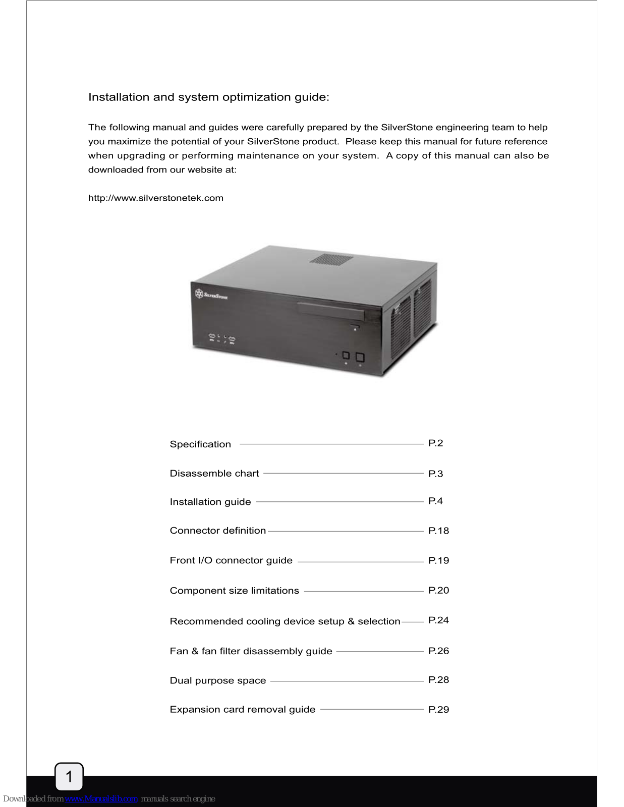
SilverStone GD04 Grandia Series, LC17, SST-GD04B-USB 3.0, SST-GD04S-USB 3.0 Manual Manual

Page 1

MANUAL

Page 2

Installation and system optimization guide:

The following manual and guides were carefully prepared by the SilverStone engineering team to help you maximize the potential of your SilverStone product. Please keep this manual for future reference when upgrading or performing maintenance on your system. A copy of this manual can also be downloaded from our website at:

http://www.silverstonetek.com

Specification ———— P.2
Disassemble chart ———————————————————————————————————— P.3
Installation guide P.4
Connector definition P.18
Front I/O connector guide P.19
Component size limitations P.20
Recommended cooling device setup & selection—— P.24
Fan & fan filter disassembly guide P.26
Dual purpose space P.28
Expansion card removal guide P.29
Page 3

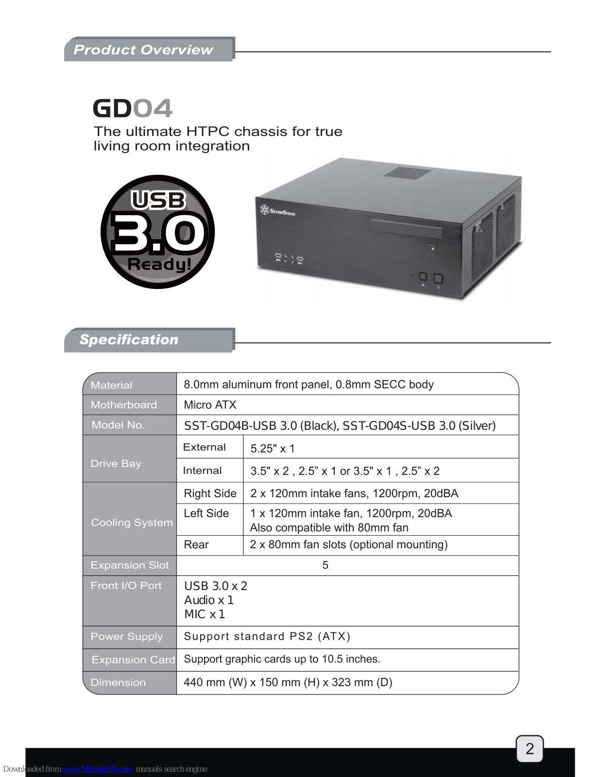
GD04

The ultimate HTPC chassis for true living room integration

Specification

Material 8.0mm aluminum front panel, 0.8mm SECC body
Motherboard Micro ATX
Model No. SST-GD04 B-USB 3.0 (Black), SST-GD04S-USB 3.0 (Silver)
External 5.25" x 1
Drive Bay Internal 3.5" x 2 , 2.5" x 1 or 3.5" x 1 , 2.5" x 2
Right Side 2 x 120mm intake fans, 1200rpm, 20dBA
Cooling System Left Side 1 x 120mm intake fan, 1200rpm, 20dBA
Also compatible with 80mm fan
Rear 2 x 80mm fan slots (optional mounting)
Expansion Slot 5
Front I/O Port USB 3.0 x 2
Audio x 1
MIC x 1
2
Power Supply Support standard PS2 (ATX)
Expansion Card Support grap ohic cards up to 10.5 inches.
Dimension 440 mm (W) x 150 mm (H) x 323 mm (D)
Page 4

Page 5

Before you begin, please make sure that you

  • (1) have all components collected
  • (2) check that all components do not have compatibility problems with each other or with the case
  • (3) if possible, assemble the components outside the case first to make sure they are working
  • (4) keep the motherboard manual ready for reference during installation.

ENGLISH

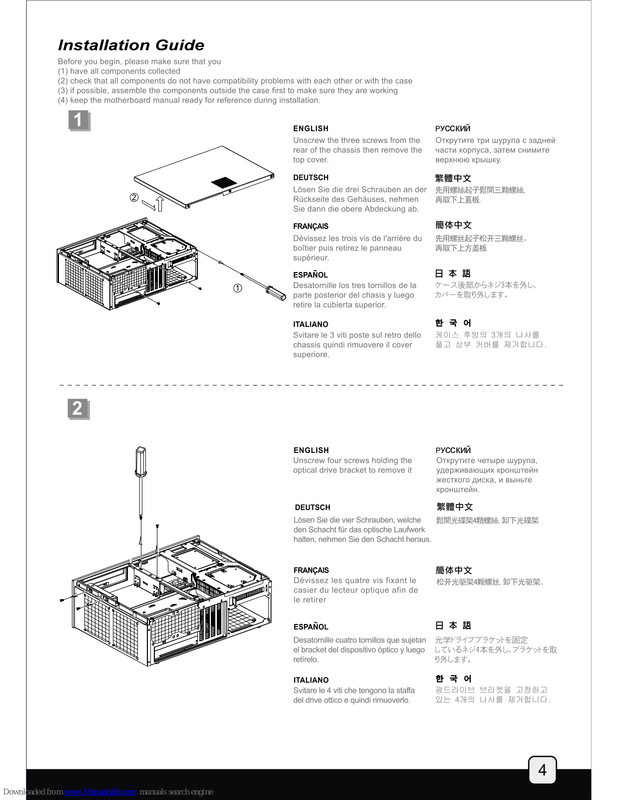
Unscrew the three screws from the rear of the chassis then remove the top cover.

DEUTSCH

Lösen Sie die drei Schrauben an der Rückseite des Gehäuses, nehmen Sie dann die obere Abdeckung ab.

FRANÇAIS

Dévissez les trois vis de l'arrière du boîtier puis retirez le panneau supérieur.

ESPAÑOL

Desatornille los tres tornillos de la parte posterior del chasis y luego retire la cubierta superior.

ITALIANO

Svitare le 3 viti poste sul retro dello chassis quindi rimuovere il cover superiore.

_____

русский

Открутите три шурупа с задней части корпуса, затем снимите верхнюю крышку.

繁體中文

先用螺絲起子鬆開三顆螺絲 再取下上蓋板

簡体中文

先用螺丝起子松开三颗螺丝, 再取下上方盖板

日本語

ケース後部からネジ3本を外し、 カバーを取り外します。

한 국 어

케이스 후방의 3개의 나사를 풀고 상부 커버를 제거합니다.

ENGLISH Unscrew four screws holding the optical drive bracket to remove it

DEUTSCH Lösen Sie die vier Schrauben, welche

den Schacht für das optische Laufwerk halten, nehmen Sie den Schacht heraus.

FRANÇAIS Dévissez les quatre vis fixant le casier du lecteur optique afin de le retirer

ESPAÑOL

Desatornille cuatro tornillos que sujetan el bracket del dispositivo óptico y luego retírelo.

ITALIANO

Svitare le 4 viti che tengono la staffa del drive ottico e quindi rimuoverlo.

русский

Открутите четыре шурупа, удерживающих кронштейн жесткого диска, и выньте кронштейн.

繁體中文 鬆開光碟架4顆螺絲、卸下光碟架

簡体中文 松开光驱架4颗螺丝, 卸下光驱架。

计元驱染4积繁丝,即下无驱杀

日本語

光学ドライブブラケットを固定 しているネジ4本を外し、ブラケットを取 り外します。

한 국 어

공드라이브 브라켓을 고정하고 있는 4개의 나사를 제거합니다.

Page 6

ENGLISH

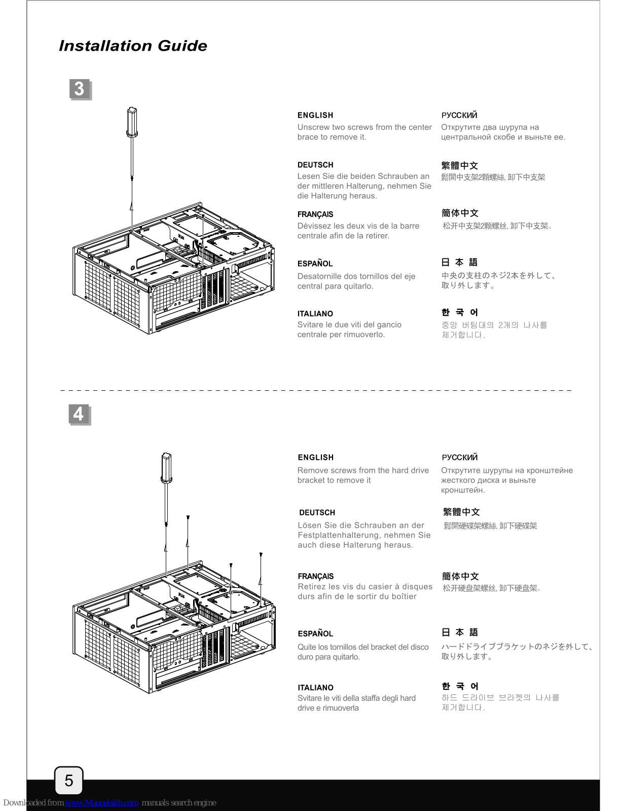
русский Открутите два шурупа на центральной скобе и выньте ее.

DEUTSCH Lesen Sie die beiden Schrauben an 鬆開中支架2顆螺絲,卸下中支架 der mittleren Halterung, nehmen Sie die Halterung heraus.

FRANCAIS Dévissez les deux vis de la barre centrale afin de la retirer.

ESPAÑOL Desatornille dos tornillos del eie central para quitarlo.

ITALIANO Svitare le due viti del gancio centrale per rimuoverlo.

_____

簡体中文 松开中支架2颗螺丝,卸下中支架。

繁體中文

日本語 中央の支柱のネジ2本を外して、

ENGLISH

DEUTSCH Festplattenhalterung, nehmen Sie auch diese Halterung heraus.

FRANCAIS Retirez les vis du casier à disques durs afin de le sortir du boîtier

ESPAÑOL Quite los tornillos del bracket del disco duro para quitarlo.

ITALIANO Svitare le viti della staffa degli hard drive e rimuoverla

русский

慜體中文 鬆開硬碟架螺絲, 卸下硬碟架

簡体中文 松开硬盘架螺丝,卸下硬盘架。

日本語 ハードドライブブラケットのネジを外して、

한 국 어 하드 드라이브 브라켓의 나사를

Page 7

5

ENGLISH

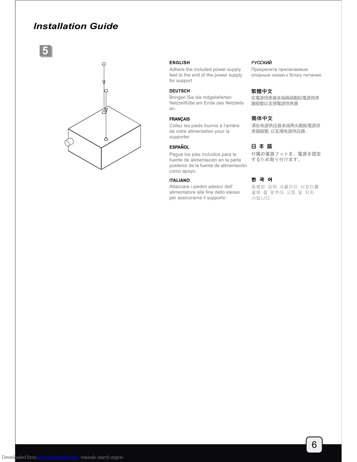
Adhere the included power supply feet to the end of the power supply for support

DEUTSCH

Bringen Sie die mitgelieferten Netzteilfüße am Ende des Netzteils an.

FRANÇAIS

Collez les pieds fournis à l'arrière de votre alimentation pour la supporter

ESPAÑOL

Pegue los pies incluidos para la fuente de alimentación en la parte posterior de la fuente de alimentación como apoyo.

ITALIANO

Attaccare i piedini adesivi dell' alimentatore alla fine dello stesso per assicurarne il supporto

русский

Трикрепите прилагаемые опорные ножки к блоку питания

繁體中文

在電源供應器末端兩端黏貼電源供應 器腳墊以支撐電源供應器

簡体中文

请在电源供应器末端两头黏贴電源供 應器腳墊,以支撑电源供应器。

日本語

付属の電源フットを、電源を固定 するため取り付けます。

한 국 어

동봉된 파워 서플라이 서포터를 끝에 잘 맞추어 고정 및 지지 시킵니다.

Page 8

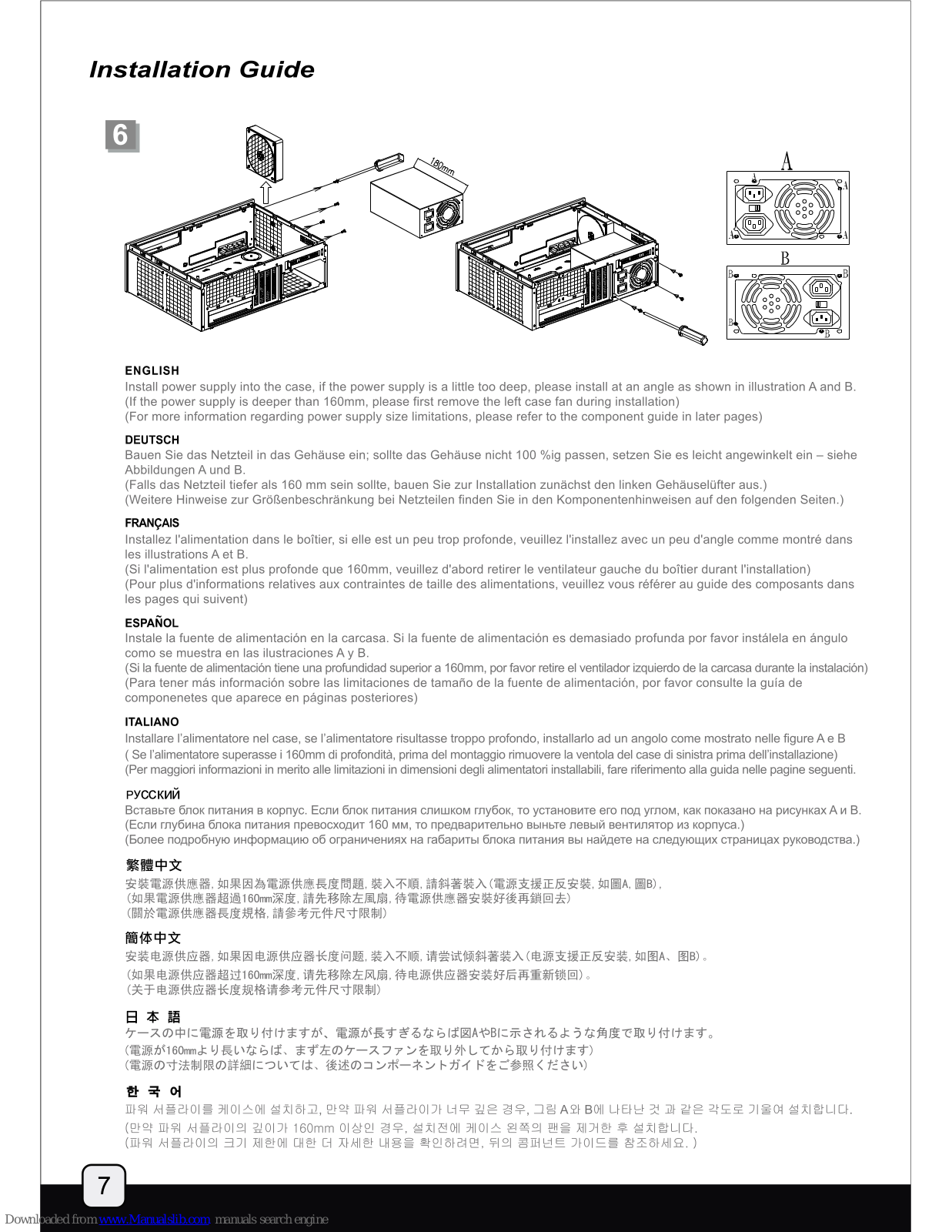
ENGLISH

Install power supply into the case, if the power supply is a little too deep, please install at an angle as shown in illustration A and B. (If the power supply is deeper than 160mm, please first remove the left case fan during installation) (For more information regarding power supply size limitations, please refer to the component guide in later pages)

DEUTSCH

Bauen Sie das Netzteil in das Gehäuse ein; sollte das Gehäuse nicht 100 %ig passen, setzen Sie es leicht angewinkelt ein – siehe Abbildungen A und B.

(Falls das Netzteil tiefer als 160 mm sein sollte, bauen Sie zur Installation zunächst den linken Gehäuselüfter aus.) (Weitere Hinweise zur Größenbeschränkung bei Netzteilen finden Sie in den Komponentenhinweisen auf den folgenden Seiten.)

FRANÇAIS

Installez l'alimentation dans le boîtier, si elle est un peu trop profonde, veuillez l'installez avec un peu d'angle comme montré dans les illustrations A et B.

(Si l'alimentation est plus profonde que 160mm, veuillez d'abord retirer le ventilateur gauche du boîtier durant l'installation) (Pour plus d'informations relatives aux contraintes de taille des alimentations, veuillez vous référer au guide des composants dans les pages qui suivent)

ESPAÑOL

Instale la fuente de alimentación en la carcasa. Si la fuente de alimentación es demasiado profunda por favor instálela en ángulo como se muestra en las ilustraciones A y B.

(Si la fuente de alimentación tiene una profundidad superior a 160mm, por favor retire el ventilador izquierdo de la carcasa durante la instalación) (Para tener más información sobre las limitaciones de tamaño de la fuente de alimentación, por favor consulte la guía de componenetes que aparece en páginas posteriores)

ITALIANO

Installare l'alimentatore nel case, se l'alimentatore risultasse troppo profondo, installarlo ad un angolo come mostrato nelle figure A e B (Se l'alimentatore superasse i 160mm di profondità, prima del montaggio rimuovere la ventola del case di sinistra prima dell'installazione) (Per maggiori informazioni in merito alle limitazioni in dimensioni degli alimentatori installabili, fare riferimento alla guida nelle pagine seguenti.

РУССКИЙ

Вставьте блок питания в корпус. Если блок питания слишком глубок, то установите его под углом, как показано на рисунках А и В. (Если глубина блока питания превосходит 160 мм, то предварительно выньте левый вентилятор из корпуса.) (Более подробную информацию об ограничениях на габариты блока питания вы найдете на следующих страницах руководства.)

繁體中文

安裝電源供應器,如果因為電源供應長度問題,裝入不順,請斜著裝入(電源支援正反安裝,如圖A,圖B), (如果電源供應器超過160mm深度,請先移除左風扇,待電源供應器安裝好後再鎖回去) (關於電源供應器長度規格,請參考元件尺寸限制)

簡体中文

安装电源供应器,如果因电源供应器长度问题,装入不顺,请尝试倾斜著装入(电源支援正反安装,如图A、图B)。 (如果电源供应器超过160mm深度,请先移除左风扇,待电源供应器安装好后再重新锁回)。 (关于电源供应器长度规格请参考元件尺寸限制)

日本語

ケースの中に電源を取り付けますが、電源が長すぎるならば図AやBに示されるような角度で取り付けます。 (電源が160mmより長いならば、まず左のケースファンを取り外してから取り付けます) (電源の寸法制限の詳細については、後述のコンポーネントガイドをご参照ください)

한 국 어

파워 서플라이를 케이스에 설치하고, 만약 파워 서플라이가 너무 깊은 경우, 그림 A와 B에 나타난 것 과 같은 각도로 기울여 설치합니다. (만약 파워 서플라이의 깊이가 160mm 이상인 경우, 설치전에 케이스 왼쪽의 팬을 제거한 후 설치합니다. (파워 서플라이의 크기 제한에 대한 더 자세한 내용을 확인하려면, 뒤의 콤퍼넌트 가이드를 참조하세요.)

Page 9

ENGLISH

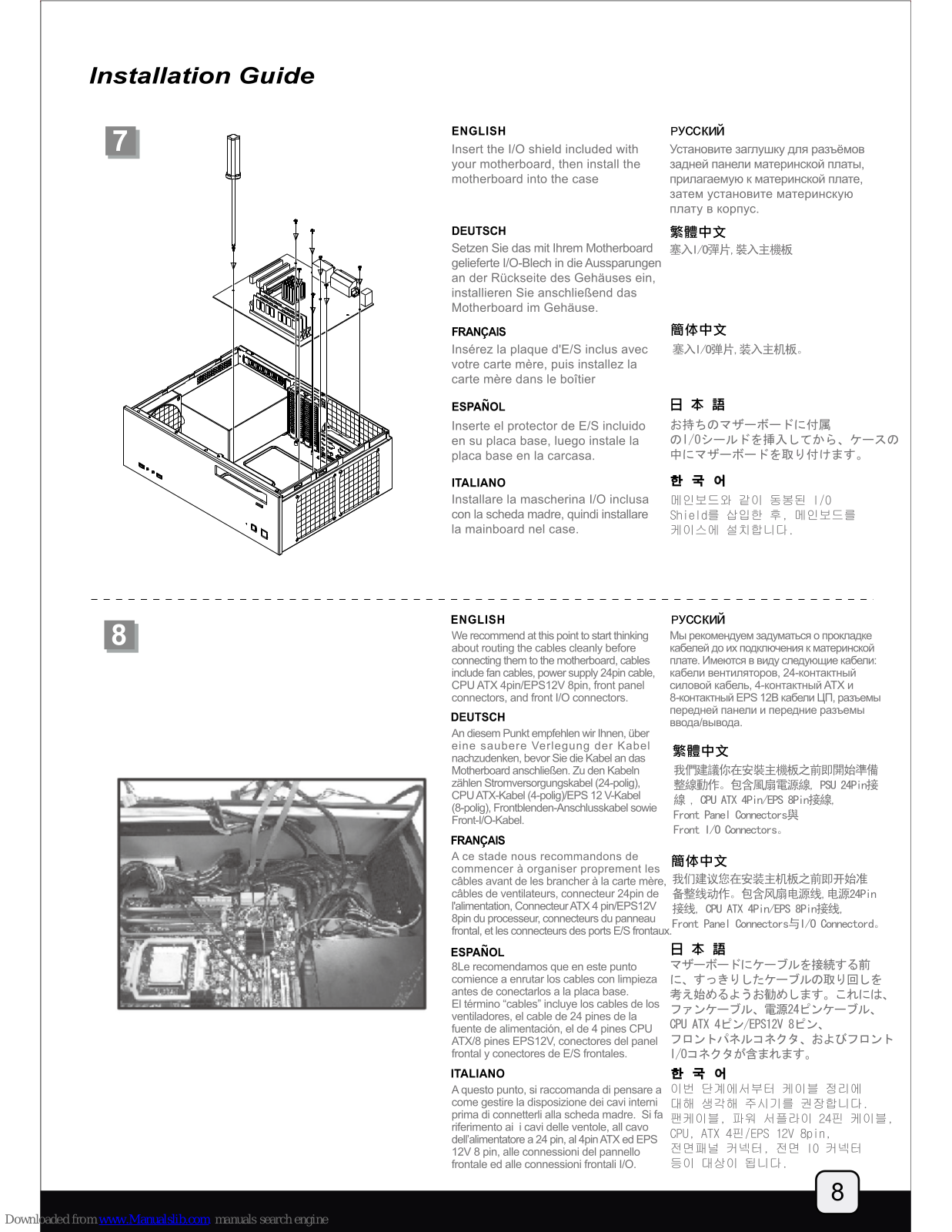
Insert the I/O shield included with vour motherboard, then install the

DEUTSCH

Setzen Sie das mit Ihrem Motherboard gelieferte I/O-Blech in die Aussparungen installieren Sie anschließend das

FRANCAIS

Insérez la plaque d'E/S inclus avec votre carte mère, puis installez la carte mère dans le boîtier

ESPAÑOL

Inserte el protector de E/S incluido en su placa base. luego instale la placa base en la carcasa.

ITALIANO

Installare la mascherina I/O inclusa con la scheda madre, quindi installare la mainboard nel case

русский

Установите заглушку для разъёмов прилагаемую к материнской плате,

繁體中文

塞入Ⅰ/0彈片, 裝入主機板

簡休中文

寒入1/0弹片,装入主机板。

日本語

お持ちのマザーボードに付屋 の1/0シールドを挿入してから、ケースの 中にマザーボードを取り付けます。

Shield를 삽입한 후, 메인보드를

ENGLISH

_____

about routing the cables cleanly before board, cables include fan cables, power supply 24pin cable, CPU ATX 4pin/EPS12V 8pin, front panel connectors, and front I/O connectors.

DEUTSCH

An diesem Punkt empfehlen wir Ihnen, über eine saubere Verlegung der Kabel nachzudenken, bevor Sie die Kabel an das Motherboard anschließen. Zu den Kabeln (ahel (24-polig) zählen Stromversorgung CPU ATX-Kabel (4-polig)/EPS 12 V-Kabel (8-polig), Frontblenden-Anschlusskabel sowie Front-I/O-Kabel.

FRANCAIS

commencer à organiser proprement les commencer a organiser proprement les câbles avant de les brancher à la carte mère. 我们建议您在安装主机板之前即开始准 câbles de ventilateurs, connecteur 24pin de l'alimentation, Connecteur ATX 4 pin/EPS12V frontal, et les connecteurs des ports E/S frontaux

ESPAÑOL

comience a enrutar los cables con limpieza antes de conectarlos a la placa base. El término "cables" incluye los cables de los ventiladores, el cable de 24 pines de la fuente de alimentación, el de 4 pines CPU ATX/8 pines EPS12V, conectores del panel frontal v conectores de E/S frontales.

ITALIANO

dell'alimentatore a 24 pin, al 4pin ATX ed EPS 12V 8 pin, alle connessioni del pannello frontale ed alle connessioni frontali I/O.

русский

繁體中文

我們建議你在安裝主機板之前即開始準備 線, CPU ATX 4Pin/EPS 8Pin接線, Front Panel Connectors與 Front 1/0 Connectors

簡体中文

备整线动作。包含风扇电源线, 电源24Pin 接线, CPU ATX 4Pin/EPS 8Pin接线, Front Panel Connectors与1/0 Connectord。

日本語

マザーボードにケーブルを接続する前 に、すっきりしたケーブルの取り回しを 考え始めるようお勧めします。これには、 ファンケーブル、電源24ピンケーブル、 CPII ATX 4ピン/EPS12V 8ピン、 1/0コネクタが含まれます。

A questo punto, si raccomanda di pensare a 이번 단계에서부터 케이블 정리에 come gestire la disposizione dei cavi interni 대해 생각해 주시기를 권장합니다 prima di connetterli alla scheda madre. Si fa 팬케이블, 파워 서플라이 24핀 케이블, 매위

Page 10

_ _ .

10

ENGLISH

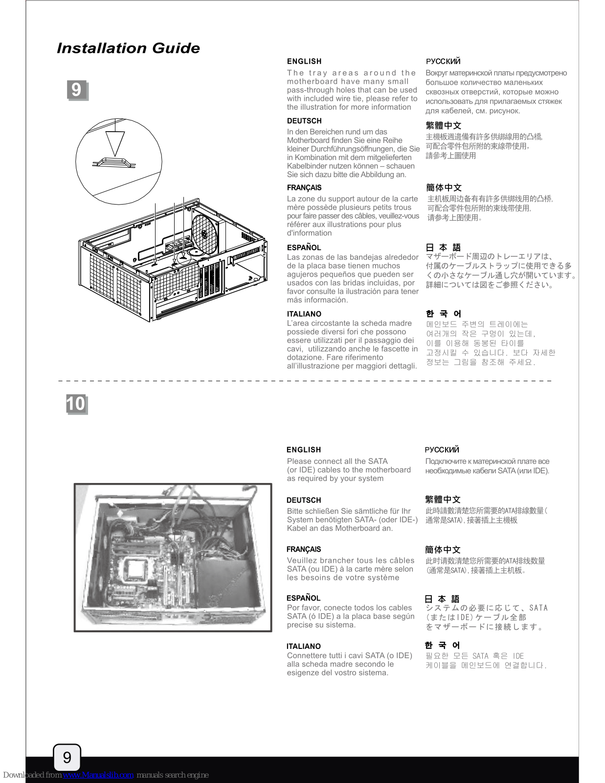
motherboard have many small pass-through holes that can be used with included wire tie, please refer to the illustration for more information

DEUTSCH

In den Bereichen rund um das kleiner Durchführungsöffnungen, die Sie in Kombination mit dem mitgelieferten Kahelhinder nutzen können – schauen Sie sich dazu bitte die Abbildung an.

FRANÇAIS

La zone du support autour de la carte mère possède plusieurs petits trous pour faire passer des câbles, veuillez-vous référer aux illustrations pour plus

ESPAÑOL

Las zonas de las bandejas alrededor de la placa base tienen muchos usados con las bridas incluidas, por favor consulte la ilustración para tener

ITALIANO

L'area circostante la scheda madre essere utilizzati per il passaggio dei cavi. utilizzando anche le fascette in all'illustrazione per maggiori dettagli.

_

русский

Вокруг материнской платы предусмотрено использовать для прилагаемых стяжек

繁體中文

主機板调邊備有許名供鄉線田的凸楂 請參考上圖使用

簡休中文

主机板周边备有有許多供绑线用的凸桥 请参考上图使用。

日本語

マザーボード周辺のトレーエリアは、 付属のケーブルストラップに使用できる多 くの小さなケーブル通し穴が開いています。 詳細については図をご参照ください。

하 국 어

메인보드 주변의 트레이에는 이를 이용해 동봉된 타이를

ENGLISH

Please connect all the SATA (or IDE) cables to the motherboard

DEUTSCH

Bitte schließen Sie sämtliche für Ihr System benötigten SATA- (oder IDE-) 通常是SATA). 接著插上主機板 Kabel an das Motherboard an.

FRANCAIS

Veuillez brancher tous les câbles SATA (ou IDE) à la carte mère selon les besoins de votre système

ESPAÑOL

Por favor, conecte todos los cables SATA (ó IDE) a la placa base según

ITALIANO

Connettere tutti i cavi SATA (o IDE) alla scheda madre secondo le esigenze del vostro sistema.

русский

Подключите к материнской плате все необходимые кабели SATA (или IDE).

繁體中文

此時請數清楚您所需要的ATA排線數量(

簡体中文

此时请数清楚您所需要的ATA排线数量 (通常是SATA),接著插上主机板。

日本語

コーー コ システムの必要に応じて、SATA (またはIDE)ケーブル全部 をマザーボードに接続します。

한 국 어

필요한 모든 SATA 혹은 IDE

Page 11

. _ _

ENGLISH

Now carefully count and separate the required power cables for your hard drive, optical drive, and graphics card. Place the needed cables out of the case and neatly place the unneeded power cables into available space inside the case

DEUTSCH

Zählen Sie nun die für Festplatte, optisches Laufwerk und Grafikkarte erforderlichen Kabel, trennen Sie diese. Führen Sie die benötigten Kabel aus dem Gehäuse heraus, platzieren Sie die nicht benötigten Kabel an einer freien Stelle innerhalb des

FRANCAIS

Maintenant compter avec attention et séparez les câbles d'alimentation requis pour vos disques durs, lecteur optique, et cartes graphiques. Placez les câbles nécessaires en dehors du boîtier et regrouper habilement les câbles non utilisé pour les loger dans l'espace disponible dans le boîtier

ESPAÑOL

Ahora cuente con cuidado y separe los cables de potencia necesarios para su disco duro, dispositivo óptico y tarjeta gráfica. Sitúe los cables necesarios por fuera de la carcasa y coloque con cuidado los que no necesite en el espacio que quede dentro de la carcasa.

ITALIANO

A questo punto contate e separate i cavi di alimentazione che vi sono necessari, quindi disponete quelli di cui non avete bisogno in una parte del case che ritenete opportuna.

русский

Теперь аккуратно пересчитайте и отделите друг от друга силовые кабели для жесткого диска, оптического диска и графической карты. Нужные кабели выгащите из корпуса, а ненужные силовые кабели аккуратно разместите внутри корпуса.

繁體中文

此時請數清楚您所需要的硬碟/光碟所需電源線、 以及顯示卡所需要的電源線、請將需要的線往外 拉出機殼、並將不需要的電源線整理並繫好

簡体中文

此时请数清楚您所需要的硬盘/光驱所需要电源线、以及显示卡所需要的电源线,请将需要的线往外拉出机箱,并将不需要的电源线整理 并系好.

日本語

I デービー ハードドライブ、光学ドライブ、 およびグラフィックカードのために必要とされる 電源ケーブルを数え、取り分けます。 ケースから必要なケーブルを確認し、ケースの 中で利用可能な空間に不要な電源 ケーブルをきちんと整理してください。

한 국 어

그후, 하드 디스크, 광드라이브 그래픽 카드에 필요한 파워 케이블의 숫자를 확인하고 분리합니다. 필요한 케이블만 케이스 밖으로 내보낸 후, 나머지 케이블은 케이스의 남은 공간에 가지런히 놓습니다.

ENGLISH

_____

The available free space in front of the motherboard and power supply has plenty of room for any excess cables to be stored and tied down using the included wire ties

DEUTSCH

Vor Motherboard und Netzteil finden Sie reichlich Platz, um überschüssige Kabel abzulegen und mit den mitgelieferten Kabelbindern zu befestigen

FRANÇAIS

L'espace libre disponible à l'avant de la carte mère et de l'alimentation peut être utilisé pour stocker les câbles supplémentaires en les groupant avec les fixations disponibles

ESPAÑOI

El espacio libre disponible en frente de la placa base y la fuente de alimentación es más que suficiente para guardar y atar cualquier cable que sobre usando las bridas.

ITALIANO

Frontalmente alla scheda madre ed all'alimentatore vi sono numerosi spazi a disposizione per riporre i cavi in eccesso, che possono essere uniti utilizzando le fascette in dotazione.

РУССКИЙ

Свободного места перед материнской платой и блоком питания вполне достаточно для размещения неиспользуемых кабелей и скрепления их прилагаемыми стяжками.

繁體中文

主機板,與電源供應器前端有相當大的位置 供放置多於線材用,請將線材放入,必要時以 束線帶固定

簡体中文

主机板,与电源供应器前端有相当大的位置供放置多馀线材用,请将线材放入,必要时以束线带固定。

日本語

Ⅰマザーボードと電源の前には、 ケーブルやリード線を取り回したり 結束したりするのに使用できる 十分なスペースがあります。

한 국 어

메인보드와 파워 서플라이 전면에는 여분의 케이블을 타이로 정리해 보관할 수 있는 충분한 공간이 마련되어 있습니다.

Page 12

_

ENGLISH Install and secure required

DEUTSCH Installieren und fixieren Sie

FRANÇAIS Installez et fixez les cartes

ESPAÑOL Instale y fije las tarjetas de

ITALIANO Installare ed assicurare al case le

русский Вставьте и закрепите карту

慜體中文

簡体中文 安装并锁固介面卡。

日本語 ______ 必要な拡張カードをインストールし、

하 국 어 필요한 확장카드를 설치하고

ENGLISH

Install and secure any 3.5" or 2.5" hard hard drive installation is to ensure complete isolation of hard drive from the bracket to

_____

DEUTSCH

Installieren und fixieren Sie 3,5- oder 將3.57硬碟與2.57 硬碟裝入硬碟架,並鎖固螺 2.5-Zoll-Festolatten mit Schrauben in der 绐 加里屬得姆級不好完合 請不要的庭恆 這 Festplattenhalterung. Die Verwendung von Schrauben zur Befestigung der Festplatten sorgt dafür, dass die Festplatten von der Halterung isoliert und Vibrationen effektiv gedämpft werde

FRANCAIS

Installez et fixez tous les disgues durs 3.5" ou 2.5" dans leur casier avec des vis. L'objectif d'utiliser des vis pour l'installation de disque durs est d'assurer une isolation complète des disques durs à partir du casier pour maximiser l'efficacité des pads anti vibrations de celui-ci.

ESPAÑOL

Instale y fije cualquier disco duro de 3,5" ó tornillos. El propósito de usar tornillos para la instalación del disco duro es asegur an succession der disco duro es asegurar ur aislamiento completo del disco duro del bracket para maximizar la efectividad anti vibración de la almohadilla.

ITALIANO

Installare ed assicurare per mezzo delle opportune viti gli hard disk da 2,5" o 3,5" in vostro possesso, alla rispettiva staffa. L'utilizzo delle viti assicura un completo isolamento del hard disk dalla staffa per massimizzare l'effetto dei pad antivibrazione.

русский

Вставьте в кронштейн для жесткого диска

繁體中文

是我們為了讓硬碟與硬碟架保持完全不接觸 發揮防震墊圈的最大效果

簡体中文

将3.5"硬盘与2.5"硬盘装入硬盘架,并锁固螺丝, 们为了让硬盘与硬盘架保持完全不接触,以发

日本語 ハードドライブブラケットの中に3.5インチまたは 2,5" en el bracket para discos duros usando 2.5インチのハードドライブをインストールし、 ネジで固定します。 ハードドライブインストールにネジを使う目的 は、防振パッドの効果を最大にするために確実 にブラケットからハードドライブが独立

필요한 3.5" 혹은 2.5" 하드 드라이브룩

Page 13

ENGLISH

There are pass-through holes next to the hard drive bracket for tidying hard drive or power cables using wire ties. There is also a rubber partition plate in the rear part of the hard drive bracket designed for channeling airflow to the top panel vents. This plate has small flaps that can be removed if need to create additional room for cables.

DEUTSCH

Neben der Festplattenhalterung finden Sie Durchführungsöffnungen, durch die Sie Signal- und Stromkabel verlegen und mit Kabelbindern fixieren können. Im hinteren Teil der Festplattenhalterung finden Sie außerdem eine Gummiplatte, die den Luftstrom zu den Öffnungen an der Oberseite regelt. Diese Platte verfügt über kleine Stege, die Sie entfernen können, falls Sie zusätzlichen Platz für Kabel benötigen sollten.

FRANÇAIS

Il y a des trous pour faire passer des câbles prés du casier à disques durs pour organiser les câbles d'alimentation et des disques durs. Il y a aussi une plaque de séparation en caoutchouc dans la partie arrière du casier à disques durs conçu pour diffuser les flux d'air vers les aérations du panneau supérieur. Cette plaque possède des petits volets qui peuvent être retirés si vous avez besoin d'espace supplémentaire pour y loger des câbles.

ESPAÑOL

Existen agujeros de pasada cerca del bracket del disco duro para ordenar los cables del disco duro o de potencia usando bridas. También hay una plancha de división de goma en la parte trasera del bracket del disco duro diseñada para canalizar el flujo de aire hacia las aberturas del panel superior. Esta plancha tiene pequeñas solapas que pueden retirarse si es necesario para crear espacio adicional para los cables.

ITALIANO

Vi sono diversi fori passanti nei pressi della staffa degli hard disk che permettono di riordinare i cavi di connessione od alimentazione utilizzando le fascette in dotazione. Nella parte posteriore della staffa è presente anche un divisorio in gomma disegnato per convogliare i I flusso d'aria verso le ventole poste sul pannello superiore, lo stesso è dotato di flap che possono essere rimossi per creare ulteriore spazio per i cavi.

русский

Рядом с кронштейном жесткого диска предусмотрены сквозные отверстия для прикрепления кабелей жесткого диска или силовых кабелей стяжками. На задней части кронштейна жесткого диска находится резиновая разделительная перегородка, которая направляет поток воздуха к вентиляционным отверстиям верхней панели. У этой перегородки есть маленькие щитки, которые можно снять и тем самым освободить дополнительное место для кабелей.

繁體中文

硬碟架側邊有綁固束線帶的凸橋,可以視需求將硬碟排線以及電源線固定,而後側硬碟架上有橡膠檔片是為了顯示卡的排風而設計的檔風罩. 上面有破孔,有需要裝設硬碟排線與電源線時,可以適度撕除部分的檔片

簡体中文

硬盘架侧边有绑固束带的凸桥,可以视需求将硬盘排线以及电源线固定,而后侧硬盘驾上的橡胶挡片是为了显示卡的排风而设计的挡风罩。 上面有破孔,如有需要装设硬盘排线与电源线时,可以适度撕除部分的档片。

日本語

ケーブルストラップでハードドライブまたは電源ケーブルを固定するよう、ハードドライブブラケットの隣にはケーブル通し用穴があります。 また、ハードドライブブラケットの後部には、気流を上部通気口に運ぶために設計されたゴム製仕切り板があります。この板には、ケーブル用の余分のスペースを用意する必要がある場合に取り外せる小さなフラップが付いています。

한 국 어

하드 드라이브 브라켓 옆에 위치한 관통 구멍들은 하드드라이브 케이블과 파워케이블을 타이로 고정시켜 선정리를 깔끔하게 하기 위해 마련되어 있습니다. 하드 드라이브 브라켓의 후방에는 고무 파티션 판이 있어 상부 패널의 배기구로 공기의 흐름을 유도하기 위해 마련되어 있습니다. 이 판에는 작은 날개가 있어 케이블을 위해 보다 많은 공간이 필요하다면 제거도 가능합니다.

Page 14

ENGLISH Reinstall hard drive bracket back

DEUTSCH Bauen Sie die Festplattenhalterung

FRANÇAIS Réinstallez le casier à disques durs dans le boîtier

ESPAÑOL Reinstale el bracket del disco duro en la carcasa.

ITALIANO Reinstallare la staffa degli hard disk nel case.

_____

русский Вставьте кронштейн жесткого диска обратно в корпус.

慜體中文 將硬碟架裝回機殼

簡体中文 请将硬盘架装回机箱。

日本語 ローキ 曲 ハードドライブブラケットをケースに 戸します。

한 국 어 -------------------------------------

ENGLISH Install and secure the optical drive onto the optical drive bracket

DEUTSCH Installieren und fixieren Sie das optische 將光碟鎖固到光碟架上 Laufwerk an der entsprechenden Halterung.

FRANCAIS Installez et fixez le lecteur optique dans son 将光驱锁固到光驱架上。

ESPAÑOL Instale y fije el dispositivo óptico en el bracket del dispositivo óptico.

ITALIANO Installare ed assicurare il drive ottico alla rispettiva staffa.

русский Вставьте оптический привод в кронштейн и закрепите его.

繁體中文

簡体中文

日本語 光学ドライブブラケットに光学 ドライブをインストールし固定します。

한 국 어 ▲ ¬ ♥ 광드라이브를 광드라이브 브라켓에 설치한 후 고정시킵니다.

Page 15

19

ENGLISH

There are pass-through holes next to Рядом с кронштейном оптического the optical drive bracket for tidying hard drive or power cables using wire отверстия для прикрепления кабелей

DEUTSCH

Neben der Halterung für das optische 光碟架側邊有綁固束線帶的凸橋. 可以視 Laufwerk finden Sie Durchführungsöffnungen, 需求將硬碟排線以及電源線固定 durch die Sie Signal- und Stromkabel verlegen und mit Kabelbindern fixieren

FRANÇAIS

Il y a des trous pour faire passer les câbles prés du casier du lecteur optique pour ranger les câbles des disques durs ou d'alimentation en utilisant les fixations.

FSPAÑOL

del bracket del dispositivo óptico para 雷源ケーブルを固定するよう、光学 ordenar los cables del disco duro o

ITALIANO

della staffa del drive ottico che permettono di riordinare i cavi di connessione od alimentazione utilizzando le fascette in dotazione.

русский

жесткого диска или силовых кабелей стяжками.

繁體中文

簡体中文

光驱架侧边有绑固束线带的凸桥,可以视

日本語

_____ ケーブルストラップでハードドライブまたは ドライブブラケットの隣にはケーブル通 し用穴があります。

한 국 어

공드라이브 브라켓 옆에는 관통

ENGLISH Reinstall the center brace back into

русский обратно в корпус.

慜體中文 Bauen Sie die mittlere Halterung 請把中支架安裝回機殼

簡体中文

日本語 ケースの中に中央の支柱を戻します。

ITALIANO Reinstallare il gancio centrale nel

Réinstallez la barre centrale

Reinstale el eje central en la

dans le boîtier.

ESPAÑOL

Page 16

ENGLISH

Test mount the optical drive bracket the optical drive button to the button on the case, if necessary, loosen the

DEUTSCH

Setzen Sie die Halterung mit dem optischen Laufwerk probeweise in das 必要時請鬆開鎖固按鍵螺絲並調整位置 wird. Lösen Sie dazu nötigenfalls die

FRANÇAIS

Testez le montage du casier du lecteur 将光驱架放上机箱并比对光驱按键位置 optique et alignez le bouton du lecteur 必要时请松开锁固的按键螺丝并调整位置。 optique avec le bouton du boîtier. si nécessaire, desserrer les vis pour

ESPAÑOI

Pruebe a meter el montaje del bracket para dispositivo óptico de nuevo en la carcasa v alinee el botón del dispositivo óptico con el botón de la carcasa, Si es necesario afloje los tornillos para realizar

ITALIANO

Testare il montaggio della staffa del drive 광드라이브 브라켓을 케이스에 ottico controllando l'allineamento del 설치하면서 광드라이브 버튼을 ottico controllando rameanendo del 필지하는지 승드라지는 하는은 pulsante del drive stesso con quello del 케이스의 버튼에 맞춥니다. 필요하다면, case, se necessario, allentare le viti di 나사를 풀어 조정을 해줍니다.

_____

влоский

Вставьте собранный кронштейн assembly back into the case and align оптического диска обратно в корпус и

慜體中文

將光碑架放上機殼並比對光碟機按鍵位置

簡体中文

日本語

ケースの中に光学ドライブブラケットアセンブリタ 試しに戻してみて、ケース上のボタンに光学 ドライブボタンの位置を合わせ、必要なら調整 のためにネジを緩めます。

! 국 어

21

-

ENGLISH

Use the included double sided tape to adhere the optical drive cover to your optical drive's door bezel

DEUTSCH

Fixieren Sie die Abdeckung des mitgelieferten doppelseitigen Klebeband an der Frontblende des

FRANCAIS

Utilisez l'autocollant double face inclus pour coller le cache du lecteur optique à la porte de celui-ci

ESPAÑOI

Use la cinta de doble cara para pegar la cubierta del dispositivo óptico al bisel de la puerta del

ITALIANO

Utilizzare il biadesivo in dotazione per far aderire il cover del drive ottico al frontalino.

русский

привода с дверцей оптического

繁體中文

將配件包內所附的光碟機擋片用雙面

簡休中文

将配件包内所附的光驱档片用双面胶

日本語

付属の両面テープで、光学 ドライブカバーをご使用の光学 ドライブのドアベゼルに固定します。

하 굿 어

Page 17

ENGLISH

Adjust the position of the optical drive bracket to align the drive cover parallel with the case front panel, make sure the optical drive button can be depressed from the button on the front panel then secure the optical drive bracket with screws.

DEUTSCH

Richten Sie die Halterung des optischen Laufwerks so aus, dass die Abdeckung des Laufwerks parallel zum vorderen Bedienfeld des Gehäuses verläuft. Achten Sie dabei darauf, dass die Taste am optischen Laufwerk von der Taste am Gehäuse betätigt wird; fixieren Sie die Halterung anschließend mit Schrauben.

FRANÇAIS

Ajustez la position du casier du lecteur optique pour aligner le cache du tiroir de manière parallèle avec la façade du boîtier, vérifiez bien que le bouton de la façade peut être pressé et relâché facilement puis fixez le casier du lecteur optique avec des vis.

ESPAÑOL

Ajuste la posición del bracket del dispositivo óptico para alinear en paralelo la cubierta del dispositivo con el panel frontal de la carcasa. Asegúrese de que el botón del dispositivo óptico puede ser deprimido del botón del panel frontal y luego asegure el bracket del dispositivo óptico con tornillos.

ITALIANO

Controllare la posizione della staffa del drive ottico in modo da allineare il cover del drive con il frontale del case, controllare il corretto funzionamento del pulsante, quindi assicurare la staffa con le viti.

русский

Отрегулируйте положение кронштейна оптического диска, чтобы крышка привода была параллельна передней панели корпуса. Убедитесь, что кнопку оптического диска можно отжать от кнопки передней панели, затем закрепите кронштейн оптического диска шурупами.

繁體中文

調整光碟架位置讓光碟機檔片平面與面板齊平,並確定可壓觸到光碟機按鈕;接著將光碟架螺絲鎖固回去

簡体中文

调整光驱架位置让光驱档片平面与片板齐平,并确定可压触到光驱按钮,接著将光驱架螺丝锁固回去。

日本語

ーー・ーー ケースのフロントパネルと面が合うようドライブカバーを位置合わせし、光学ドライブボタンがフロントパネル上のボタンから押し下げられることが可能 なのを確かめてから、光学ドライブブラケットのポジションを調整して、光学ドライブブラケットをネジで固定します。

한 국 어

드라이브 커버가 케이스 전면 패넬과 일치 되도록 광드라이브 브라켓을 조정합니다. 광드라이브 단추가 잘 눌러지는지 확인한 후 광드라이브 브라켓의 나사를 최종적으로 고정시킵니다.

Page 18

ENGLISH

Place the top cover back onto the case and secure with three screws.

DEUTSCH

Setzen Sie die obere Abdeckung

FRANÇAIS 簡休中文 Remettez le panneau supérieur sur le 请将上侧板盖回,并锁固三颗螺丝。 boîtier et fixez-le avec trois vis,

ESPAÑOL 日本語 Vuelva a poner la cubierta superior en ケースに上部カバーを戻し、ネジ3本 la carcasa y asegúrela con tres tornillos. で固定します。

ITALIANO Riposizionare il cover superiore e serrarlo per mezzo delle tre viti

русский

Установите на место верхнюю крышку корпуса и закрепите ее

繁體中文 請將上蓋板蓋回去, 並鎖固三顆螺絲

한 국 어 상부 커버를 케이스에 재 설치한

ENGLISH Installation complete

_

DEUTSCH Die Installation ist damit abgeschlossen.

FRANÇAIS Installation terminée

ESPAÑOL Instalación finalizada.

ITALIANO Installazione completata

РУССКИЙ Сборка завершена.

繁體中文 安裝完成

簡体中文 安裝完成。

日本語 インストールは完了です。

한 국 어 설치가 완료 되었습니다.

Page 19

Connector definition

(1) Front panel connector installation

ENGLISH

Power switch and reset switch installation guide: Please refer to the motherboard manuals for the motherboard's "Front Panel Connector" or "System Panel Connector" pin definition. Power switch and reset switch have no polarity, so they can be connected in any orientation.

Ein-/Ausschalter und Rücksetztaste (Reset) installieren: Bitte suchen Sie in der Motherboard-Dokumentation nach der Pinbelegung der Anschlüsse des Frontbedienfeldes ("Front Panel Connectors" oder " System Panel Connectors"). Ein-/Austaste und Rücksetztaste benötigen keine bestimmte Polarität, können daher beliebig (ohne auf + und - zu achten) angeschlossen werden.

FRANÇAIS

Guide d'installation des interrupteurs d'allumage et de réinitialisation : Veuillez-vous référer au manuel de votre carte mère pour la description des broches "des connecteurs du panneau frontal" et des broches "des connecteurs du panneau système". Les interrupteurs d'allumace et de réinitialisation ne possède pas de polarité, donc ils peuvent être branché dans les deux sens.

ESPAÑOL

Guía de instalación de los interruptores de encendido y reseteo: Por favor, consulte en los manuales de la placa base la configuración de pines del "Conector de panel frontal" ó "Conector de panel de sistema" de su placa base. Los interruptores de encendido y reseteo no tienen polaridad, luego se pueden conectar con cualquier orientación.

ΙΤΔΙ ΙΔΝΟ

Guida all'installazione dei connettori Power Switch e Reset Switch Guida all'installazione dei connettori Power Switch e Reset Switch Fare riferimento al manuale della scheda madre nella sezione "Connettori del pannello frontale" o "Connettori del pannello di sistema". Power switch e reset switch non hanno polarità, posso essere pertanto connessi con qualsiasi orientamento.

русский

繁體中文

▲ ch 與Reset Switch安裝說明: 請參考主機說明書的Front Panel Connectors安裝Pin Define,將Connector插上; Power Switch 與Reset Switch並無正負極性之分,反插正插都不影響功能性。

簡体中文

一〇 wer Switch 与Reset Switch安装说明:

请参考主机说明书的Front Panel Connectors 安装Pin Define,将Connector插上;

日木語

□ 4 戸 電源スイッチおよびリセットスイッチのインストールガイド: マザーボードの「フロントパネルコネクタ」または「システムパネルコネクタ」のピン配列 についてはマザーボードマニュアルを参照してください。電源スイッチとリセットスイッチに 極生ないので、いずれの方向でも、接続できま

_____________________________________

ENGLISH

i

LED connector installation guide : Please refer to the motherboard manuals for the motherboard's "Front Panel Connector" or "System Panel Connector" pin definition. : the white wires are negative while other colors are positive wires. The Power LED wires are separate pins for compatibility with different motherboard pin definition so please make sure they are connected in the right polarity by referring to your motherboard manual.

DEUTSCH

LED-Verbinder installieren: Bitte suchen Sie in der Motherboard-Dokumentation nach der Pinbelegung der Anschlüsse des Frontbedienfeldes ("Front Panel Connectors" oder "System Panel Connectors"). Die weißen Adem sind negativ (-), die farbigen Adem positiv (+).Die Kabel für die Betriebsanzeige-LED sind zur Kompatibilität mit unterschiedlichsten Motherboards einzeln, nicht als kompletter Stecker ausgeführt. Achten Sie hier bitte auf die richtige Polarität, lesen Sie in der Dokumentation Ihres Motherboards nach. FRANCAIS

FRANÇAIS Guide d'installation du connecteur LED : Veuillez-vous référer au manuel de votre carte mère pour la description des broches "des connecteurs du panneau frontal" et des broches "des connecteurs du panneau système". Les câbles colorés en blanc sont négatifs alors que ceux d'une autre couleur sont positifs. Les câbles de la LED Power sont séparés afin d'être compatible avec différentes cartes mères, donc vérifiez bien qu'ils sont branchés avec la bonne polarité en vous référant au manuel de votre carte mère.

ESPAÑOL

ESPAÑOL Guía de instalación del conector LED: Por favor, consulte en los manuales de la placa base la configuración de pines del "Conector de panel frontal" ó "Conector de panel de sistema" de su placa base. Los cables de color blanco son negativos mientras que los de color son positivos. Los cables LED de potencia tienen pines separados para compatibilidad con diferen Los cables LEU de potencia tienen pines separados para compatibilidad con definiciones de pines de la placa base luego por favor, asegúrese de que está conectados en la polaridad correcta consultando el manual de su placa base.

Guida all'installazione del connettore LED Fare riferimento al manuale della scheda madre nella sezione "Connettori del pannello frontale" o "Connettori del pannello di sistema". I cavi di colore bianco sono il polo negativo, mentre quelli di colore diverso il positivo. Guida all'installazione del Power Led serie RV/KLConnettere direttamente il connettore ad un molex dell'alimentatore

русский

繁體中文

LEU按頭女装説明: 請參考說明書的Front Panel Connectors安裝Pin Define,將Connector插上: 白色線的部分為

簡体中文

请参考说明书的Front Panel Connectors安装Pin Define.将Connector插上: 白色线的部份为负极.

日本語

-------------------------------------ロビコネン メのインスト・ルカイト・ マザーボードの「フロントパネルコネクタ」または「システムパネルコネクタ」 ピン配列 マサーホートの「フロフトハネルコネクタ」または「フステムハネルコネクタ」とつ配列 についてはマザーボードマニュアルを参照してください。白色のリード線はマイナスで、色の着 いたリード線がプラスです。電源田リード線は種々のマザーボードピン定義と互換性を持 たせるため分離されたピンとなっているので、ご使用のマザーボードマニュアルを参照して、 適切な極性に接続されるようお確かめください。

한 국 어

-테 설치 가이드

18

Page 20

Front I/O connector guide

ENGLISH

Below are the front I/O connectors pin definition, please also check your motherboard manual to cross reference with motherboard's front I/O pin headers. SilverStone's I/O connectors are in block type to simplify installation.

DEUTSCH

Nachstehend finden Sie die Pinbelegung der Front-I/O-Verbinder; bitte gleichen Sie diese Angaben mit der Belegung der Front-I/O-Anschlüsse ab – diese Angaben finden Sie in Ihrer Motherboard-Dokumentation. Zur einfacheren Installation sind die SilverStone-I/O-Verbinder in einem kompletten Block zusammengefasst.

FRANÇAIS

Au dessous de la description des broches des ports d'E/S, veuillez aussi vérifier sur le manuel de votre carte mère de manière croisée que les broches sont correctement placées. Les connecteurs d'E/S de SilverStone sont en bloc pour en simplifier leur installation.

ESPAÑOL

A continuación tiene la definición de pines de los conectores frontales de E/S, también debe consultar el manual de su placa base para comprobar la referencia de los pines para E/S frontales. Los conectores de E/S de SilverStone son de bloque para simplificar la instalación.

РУССКИЙ

Ниже приведено описание контактов передних разъемов ввода/вывода. Обратитесь также к руководству пользователя материнской платы за описанием передних разъемов ввода/вывода типа "пин-хедер". Разъемы ввода/вывода "SilverStone" - блочного типа, что облегчает сборку.

ITALIANO

Di seguito lo schema delle connessioni I/O frontali, confrontare lo schema con quanto riportato sul manuale della scheda madre per effettuare una controllo incrociato. I connettori I/O Silverstone, per semplificare l'installazione, sono del tipo "a blocco".

한 국 어

아래는 전면 I/O 커넥터의 핀 사양이 나타나 있습니다. 메인보드 매뉴얼을 참조하여, I/O핀 을 재차 확인합니다. Silverstone의 I/O 커넥터는 블록으로 되어 있어 설치가 용이합니다.

日本語

以下はフロントI/0コネクタピン配列ですが、お持ちのマザーボードのフロントI/0ピンヘッダは、マザーボードマニュアルをご参照ください。シルバーストーンのI/0コネクタは、インストールの容易なブロックタイプになっています。

繁體中文

下表為Front I/O Connectors的Pin Define,請參閱主機板說明書的各Front I/O Connectors Pin Define——核對。 GD04的Front I/O Connectors完全採用集合Pin方式以簡化安裝。

簡体中文

下表为Front I/O Connectors的Pin Define,请参阅主机板说明书的各Front I/O Connectors Pin Define——核对。 GD04的Front I/O Connectors完全采用集合Pin方式以简化安装。

Page 21

Component size limitations

The GD04 was designed to be as small as possible while maximizing interior space usage, please refer to the following guidelines for component selection and future upgrade considerations.

CPU cooler height limitation

ENGLISH

When optical drive is used, the GD04 has 70mm height limitation for CPU cooler. If no optical drive is installed, the height limit for CPU cooler increases to 120mm If a silent CPU cooling solution is required, we recommend using the SilverStone NT01-E in fanless configuration for 65W rated or lower CPUs.

DEUTSCH

Wenn Sie ein optisches Laufwerk verwenden, darf der CPU-Kühler beim GD04 maximal 70 mm hoch sein. Falls kein optisches Laufwerk installiert wird, können Sie CPU-Kühler mit einer Höhe bis 120 mm verwenden. Sofern Sie auf eine lautlose CPU-Kühlung Wert legen, empfehlen wir für CPUs bis 65 W den Kühler SilverStone NT01-E in lüfterloser Ausführung.

FRANÇAIS

Lorsque l'emplacement du lecteur optique est utilisé, le GD04 peut accueillir un dissipateur de processeur de d'une hauteur de 70mm. Su aucun lecteur optique n'est installé, le dissipateur du processeur peut avoir une hauteur de 120mm Si une solution de refroidissement silencieuse est requise, nous recommandons l'utilisation du SilverStone NT01-E dans une configuration sans ventilateurs pour les processeurs de 65W ou moins.

ESPAÑOL

Lorsque l'emplacement du lecteur optique est utilisé, le GD04 peut accueillir un dissipateur de processeur de d'une hauteur de 70mm. Su aucun lecteur optique n'est installé, le dissipateur du processeur peut avoir une hauteur de 120mm Si une solution de refroidissement silencieuse est requise, nous recommandons l'utilisation du SilverStone NT01-E dans une configuration sans ventilateurs pour les processeurs de 65W ou moins.

РУССКИЙ

Если используется оптический привод, то максимальная высота кулера ЦП для корпуса GD04 - 70 мм. Если оптический привод не установлен, то максимальная высота кулера ЦП увеличивается до 120 мм. Если требуется бесшумное охлаждение ЦП, мы рекомендуем использовать SilverStone NT01-E без

ITALIANO

Quando vengono utilizzati drive ottici, il GD04 può accogliere dissipatori alti max 70mm. Se non vengono utilizzati drive ottici la misura sale a 120mm. Se è necessaria una configurazione silenziosa, vi suggeriamo di utilizzare il dissipatore SilverStone NT01-E in configurazione fanless per cpu da 65W o meno.

한 국 어

공드라이브 사용시에 GD04는 70mm 까지의 CPU 쿨러 사용이 가능하며, 광드라이브를 사용하지 않을 경우 CPU 쿨러의 높이 제한은 120 mm 로 늘어납니다. 무소음 CPU 냉각 솔루션이 필요할 경우 Sileverstone의 NT01-F 를 무팬 상태로 사용하시길 권장합니다.

무소음 CPU 냉각 솔루션이 필요할 경우 Sileverstone의 NT01-E 를 무편 상태로 사용하시길 권경

日本語

光学ドライブが使われる時、GD04はCPUクーラーに対して70mmの高さ制限があります。いずれの光学ドライブもインストールされないならば、 CPUクーラーのための高さ制限は120mmまで増大します。 静かなCPU冷却ソリューションが必要とされているならば、定格65W以下のCPUを対象として、ファンレス構成でシルバーストーンNTO1-Eを使うようお勧めします。

繁體中文

GD04在光碟機涵蓋的部分CPU Cooler限高為70mm,在光碟機沒有涵蓋的部分CPU Cooler限高為120mm。 如果需要安靜的CPU Cooler,我們建議你可以使用NT01-E Fanless可以支援65W的CPU

簡体中文

GD04在光驱涵盖的部份CPU Cooler限高为70mm,在光驱没有涵盖的部份CPU Cooler限高为120mm。 如果需要安静的CPU Cooler,我们建议你可以使用NT01-E Fanless可以支援65W的CPU

Page 22

Power supply length limitation

The allowable power supply length is determined by the left intake fan size. Please refer to the table below as a guide when choosing the appropriate power supply.

ENGLISH
Left case fan at 120mm Left case fan at 80mm
Non-modular PSU PSU length limit is 180mm Netzteil-Maximallänge: 220 mm
Example ZU1200M OP1200
Modular PSU PSU length limit is 160mm Netzteil-Maximallänge: 200 mm
Example ST70F ST1000

The interior of the GD04 was designed with cable routing and room for excess cables. Storing cables in the designated area of the case will have no impact to the case's structure and airflow. Depending on your hardware component requirement, we recommend the following SilverStone non-modular power supplies, OP1000-E, ST70EF, ST50F, and ST40NF. (power supply with 650mm long 8pin EPS12V or 4pin ATX12V cable is highly recommended)

DEUTSCH

Linker Gehäuselüfter: 120 mm Linker Gehäuselüfter: 80 mm
Nicht-modulares Netzteil Netzteil-Maximallänge: 180 mm Netzteil-Maximallänge: 220 mm
Beispiel ZU1200M OP1200
Modulares Netzteil Netzteil-Maximallänge: 160 mm Netzteil-Maximallänge: 200 mm
Beispiel ST70F ST1000

Das Innere des GD04 bietet Möglichkeiten zum sauren Verlegen der Kabel und zusätzlich ausreichend Platz zum Unterbringen überschüssiger Kabel. Das Ablegen nicht benötigter Kabel an den dafür vorgesehenen Stellen wirkt sich nicht negativ auf Stabilität und Luftzirkulation aus. Je nach Konfiguration Ihres Systems empfehlen wir die folgenden, nicht-modularen SilverStone-Netzteile: OP1000-E, ST70EF, ST50F und ST40NF. (Ein Netzteil mit 650 mm langen EPS 12 V-Kabeln (8-polig) oder ATX 12 V-Kabeln (4-polig) wird dringend empfohlen.)

FRANÇAIS

- Ventilateur gauche de 120mm Ventilateur gauche de 80mm
Alimentation Non-modulaire La taille maxi de l'alimentation est de 180mm La taille maxi de l'alimentation est de 220mm
Exemple ZU1200M OP1200
Alimentation Modulaire La taille maxi de l'alimentation est de 160mm La taille maxi de l'alimentation est de 200mm
Exemple ST70F ST1000

L'intérieur du GD04 a été conçu avec un système de routage des câbles et avec un peu d'espace supplémentaires pour ceux-ci. Le stockage des câbles dans les zones dédiées du boîtier n'aura pas de conséquences sur les flux d'air. Selon les exigences de vos composant matériel, nous vous recommandons les alimentations non modulaire suivantes, OP1000-E, ST70EF, ST50F, et ST40NF. (alimentation avec connecteur 8pin EPS12V ou 4pin ATX12V de 650mm de long est grandement recommandé)

ESPAÑOL
Ventilador de carcasa izquierdo: 120mm Ventilador de carcasa izquierdo: 80mm
FA no modular Límite de longitud de la FA: 180mm Límite de longitud de la FA: 220mm
Ejemplo ZU1200M OP1200
FA modular Límite de longitud de la FA: 160mm Límite de longitud de la FA: 200mm
Ejemplo ST70F ST1000

El interior de la GD04 fue diseñado con enrutado de cables y espacio de sobra para los cables. El hecho de almacenar cables en la zona destinada para ello en la carcasa no tendrá impacto para la estructura y flujo de aire de la carcasa. Dependiendo de los requerimientos de sus componentes, recomendamos las siguientes fuentes de alimentación no modulares de SilverStone: OP1000-E, ST70EF, ST50F y ST40NF. (Se recomienda encarecidamente que la fuente de alimentación tenga un cable de 650mm de longitud de 8 pines EPS12V ó 4 pines ATX12V).

Page 23
русский
Левый вентилятор 120мм Левый вентилятор 80 мм
Немодульный БП Ограничение на длину блока питания - 180 мм Ограничение на длину блока питания - 220 м
Пример ZU1200M OP1200
Модульный БП Ограничение на длину блока питания - 160 мм Ограничение на длину блока питания - 200 м
Пример ST70F ST1000

Внутренность корпуса GD04 предназначена для прокладки кабелей, внутри корпуса предусмотрено место для неиспользуемых кабелей. Хранение кабелей в предназначенных для них местах не влияет на структуру корпуса и воздушный поток. В зависимости от используемых компонент мы рекомендуем следующие немодульные блоки питания "SilverStone": OP1000-E, ST70EF, ST50F и ST40NF. (Настоятельно рекомендуется использование блока питания с 650-миллиметровым 8-контактным кабелем EPS12B или 4-контактным ATX12B.)

ITALIANO

-- - -

Vetola sinistra del case 120mm Ventola sinistra del case 80mm
PSU Non-modulare Limite di lunghezza PSU 180mm Limite di lunghezza PSU 220mm
Esempio ZU1200M OP1200
PSU Modulare Limite di lunghezza PSU 160mm Limite di lunghezza PSU 200mm
Esempio ST70F ST1000

L'interno di GD04 è stato disegnato per avere diverse aree dove riporre i cavi in eccesso. Disporre i cavi nelle aree designate non avrà alcun impatto sui flussi d'aria interni al case. A seconda della richiesta, dettata dai vostri componenti, vi raccomandiamo l'utilizzo dei seguenti alimentatori SilverStone non modulari : OP1000-E, ST70EF, ST50F, and ST40NF. (Sono altamente raccomandati alimentatori che possiedano un cavo 8pin EPS12 o 4 pin ATX12V lungo almeno 650mm)

한 국 어 좌측 120mm 케이스팬 적용시 좌측 80mm 케이스팬 적용시
Non-modular PSU PSU 길이제한 180mm PSU 길이제한 220mm
예시 ZU1200M OP1200
Modular PSU PSU 길이제한 160mm PSU 길이제한 200mm
Example ST70F ST1000

GD04의 내부는 케이블 정리와 남는 케이블을 저장할 수 있는 공간을 확보하기 위해 디자인되었습니다. 이러한 공간에 케이블을 저장하는 것은, 케이스의 구조나 공기의 흐름에 거의 영향을 주지 않습니다.

하드웨어 부품에 따라 다르지만, 실버스톤의 비 모듈러 파워 서플라이를 권장합니다. (OP1000-E, ST70EF, ST50F, ST40NF) (길이 650mm 이상의 길이의 8pin EPS12V 또는 4pin ATX12V 케이블을 권장합니다.)

日 4 語 120mmの左側ケースファン 80mmの左側ケースファン
非モジュールタイプPSU PSU長さ限界は180mm。 PSU長さ限界は220mm。
ZU1200M 0P1200
モジュールタイプPSU PSU長さ限界は160mm。 PSU長さ限界は200mm。
ST70F ST1000

GD04の内部はケーブル取り回しとケーブルのための十分のスペースがあるよう設計されました。ケースに示されたエリアにケーブルを収 めるなら、ケースの構造とエアの流れに全く影響しません。ハードウェアコンポーネントの必要条件に依存して、当社は以下の シルバーストーン製非モジュールタイプ電源、OP1000-E、ST70EF、ST50F、およびST40NFを推薦します。 (650mm長8ピンEPS12Vまたは4ピンATX12Vケーブル装備の電源を強くお推めします)

繁體中文
機殼左側使用120mm風扇 機殼左側使用80mm風扇
非模組化PSU PSU長度限制180mm PSU長度限制220mm
例如 ZU1200M 0P1200
模組化PSU PSU長度限制160mm PSU長度限制200mm
例如 ST70F ST1000

因為GD04在機殼內有適度保持相當的整線空間與理線規劃。即使有大量的多餘線材,也不影響到安裝性與氣流。我們建議可以採用0P1000-E, ST70EF, ST50F, ST40NF…等直出線的電源供應器。(我們強烈推薦0P1000-E,因為0P1000-E的EPS 8Pin線長足夠,可以繞主機板一周的方式理線)

簡体中文

机箱左侧使用120mm风扇 机箱左侧使用80mm风扇
非模组化PSU PSU长度限制180mm PSU长度限制220mm
例如 ZU1200M 0P1200
模组化PSU PSU长度限制160mm PSU长度限制200mm
例如 ST70F ST1000

因为GD04在机箱内有保持相当的整线空间与理线规划。即使使用大量的多馀线材,也不影响到安装性与气流。我们建议可以采用OP1000-E, ST70EF, ST50F, ST40NF…等直出线的电源供应器。(我们强烈推荐OP1000-E,因为OP1000-E的EPS 8Pin线长足够,可以绕主机板一周的方式理线)。

Page 24

Graphics card/expansion card length limitation GD04 can support 10.5"(267mm) consumer level graphics cards

Optical drive cover limitations

ENGLISH

In keeping the styling of GD04 front panel clean, an optical drive cover is provided to cover the drive. Optical drives with full-width bezel cover are not compatible. Please refer to the images as a guide for compatible optical drives.

DEUTSCH

IDamit die Front Ihres GD04 optisch ansprechend wirkt, wird eine spezielle Frontblende mitgeliefert. Optische Laufwerke mit Frontblenden in voller Breite sind nicht kompatibel. Bitte schauen Sie sich die Abbildungen an, um ein Gefühl für die richtige Ausführung zu erhalten.

FRANÇAIS

Pour garder le style sobre du panneau frontal du GD04, un cache de lecteur optique est fourni. Les lecteurs optiques avec un charriot prenant toute la largeur ne sont pas compatibles. Veuillez vous référer aux images suivantes comme quide de compatibilité des lecteurs optiques.

ESPAÑOL

Para conservar el estilo limpio del panel frontal de la GD04, se proporciona una cobertura para tapar el dispositivo. Los dispositivos ópticos con cobertura de bisel completo no son compatibles. Por favor, consulte las imágenes como guía de dispositivos ópticos compatibles.

русский

В модели GD04 на передней панели предусмотрена крышка оптического привода. Нельзя использовать оптические приводы с крышкой во всю ширину. Совместимый и несовместимый оптические приводы показаны на рисунке.

ITALIANO

Per preservare la pulizia dello stile del forntale di GD04, è previsto un cover per i drive ottici. I drive con lo sportello a piena larghezza non sono compatibili. Fare riferimento alle immagini come guida per la scelta dei drive ottici.

한 국 어

GD04의 전면패널의 스타일링을 위해, 광드라이브 커버가 기본 제공됩니다. 다만, 베젤이 드라이브 전체를 덮는 방식의 광드라이브는 호환이 되지 않으므로 주의 바라며, 아래 그림을 참조하시기 바랍니다.

日本語

GD04フロントパネルのスタイリングをすっきりさせるよう、ドライブを覆う光学ドライブカバーが用意されています。 幅広のベゼルカバーを持つ光学ドライブは互換性がありません。互換性のある光学ドライブについては図をご参照ください。

繁體中文

GD04為了整體外觀的一致性,光碟機採用隱藏式的設計。部分門板較大的光碟機可能不相容於GD04。 請參考以下圖面確認光碟機門板大小位置以及按鍵的位置來判斷是否相容於您需要的光碟機。

簡体中文

GD04为了整体外观的一致性,光驱采用隐藏式设计。部分门板较大的光驱可能不相容于GD04。 请参考以下图面确认光驱门板大小位置以及按键的位置来判断是否相容于您需要的光驱。

Incompatible optical drive

Compatible optical drive

23

Manualslib.com, manuals soorsb.ong

Page 25

Recommended cooling device setup and selection

When choosing a graphics card, we recommend models that have fan blowing exhaust air to the rear slot, this will ensure smooth and efficient airflow within the GD04 for maximum cooling performance.

Cable routing

ENGLISH

recommend models that have fan blowing exhaust air to the rear slot, this will ensure smooth and efficient airflow within the GD04 for maximum cooling performance.

DEUTSCH

Wenn Sie eine Grafikkarte auswählen, empfehlen wir Modelle mit Lüftern, die die Abluft in Richtung des hinteren Steckplatzes blasen; dies gewährleistet eine problemlose und effiziente Luftbewegung innerhalb des GD04 und somit eine maximale Kühlungsleistung.

FRANCAIS

nous recommandons les modèles qui ont des ventilateurs qui soufflent en extraction par l'équerre arrière, ceci assurera un flux d'air régulier et efficace dans le GD04 pour des nances de refroidissement maximales

ESPAÑOL

Cuando escoja una tarjeta gráfica, le recomendamos modelos que tengan la salida de aire del ventilador orientada hacia la parte trasera, de este modo asegurará un fluio de aire suave v eficiente dentro de la GD04 para un rendimiento máximo de la refrigeración.

ITALIANO

Quando scegliete una scheda grafica. vi raccomandiamo di optare per un modello che espella l'aria al di fuori del case, questo assicurerà un più efficiente flusso d'aria e massimizzerà le prestazioni di raffreddamento

русский

繁體中文

為朝向Slot端的方式,這樣安裝上GD04時, 書執會儘量優先由機殼上蓋的開孔洩出, 以避免機殼內的積熱

簡休中文

如果您安装高端显示卡 我们建议您诜购风向 为朝向Slot端的方式,这样安装上GD04时,

日本語

グラフィックカードを選ぶ際、ファン送風が後部 スロット方向に排気を行うモデルを推奨します。 最大の冷却性能を実現します。

하 국 어

그래픽 카드 선택시에 쿨링 팬이 활장슬롯

_

ENGLISH We placed pass-through holes in various front of the power supply, and next to the hard drive, etc... Please use wire ties in places as needed by your hardware

DEUTSCH

An verschiedenen Stellen des Gehäuses – beispielsweise um das Motherboard herum, vor dem Netzteil, neben den Festplatten und an anderen Stellen – erleichtern Durchführungsöffnungen das saubere Verleger

der Kabel. Bitte setzen Sie Kabelbinder an Steller ein, an denen Ihre Hardwarekonfiguration dies erlaubt.

FRANÇAIS

Nous avons placés des trous pour faire passer des câbles à plusieurs endroits comme par exemple autour de la carte mère, à l'avant de l'alimentation et à côté des disques durs etc... Veuillez utilisez les système d'attache déjà présent selon les besoins de votre configuration matérielle.

ESPAÑOL

puntos: cerca de la placa base, frente a la fuente de alimentación y cerca del disco duro, etc. Por favor, use bridas en los lugares que

ITALIANO

sono presenti dei for passanti in vari punti, come intorno alla scheda madre. frontalmente all'alimentatore, nei pressi degli hard disk, ecc. Usare le fascette in dotazione a seconda di quanto richiesto dalla vostra configurazione.

русский

繁體中文

上與顯示卡前端安置可以容纳束線帶的凸橋 請依指示將適當的線材綁在適當的位置

簡体中文

我们有在主机板周边, 电源供应器前方, 磁架 请依指示将适当的线材绑在适当的位置。

日本語

マザーボードには、いくつかの穴が雷源の前 とハードドライブの隣などケーブル用に用意 されています。ご使用のハードウェア構成の必要に合 わせて、ケーブルストラップを適所にご使用ください

명리를 하기 위해서는 파워서플라이 앞쪽이나 하드드라이브 주변의 홀을 이용합니다.

Page 26
Upgrading case far

ENGLISH

SilverStone already includes three 120mm low noise fans in the GD04. The fans are selected to maintain class-leading cooling performance while keeping noise to minimum. If you wish to increase air exhaust speed around the CPU, there are two 80mm fan slots for adding additional fans. For this, we recommend the use of SilverStone's SUSCOOL81.

DEUTSCH

SilverStone setzt drei geräuscharme 120-mm-Lüfter im GD04 ein. Dabei handelt es sich um ausgesuchte Lüfter, die eine hervorragende Kühlungsleistung bieten, aber dennoch besonders leise arbeiten. Falls Sie den Luftstrom um die CPU weiter verbessern möchten, stehen Ihnen zwei Öffnungen für zusätzliche 80-mm-Lüfter zur Verfügung. Wir empfehlen die SilverStone-Lüfter SUSCOOL81.

FRANÇAIS

SilverStone a déjà inclus trois ventilateurs silencieux de 120mm dans le GD04. Les ventilateurs ont été sélectionnés pour obtenir des performances de refroidissement de première catégorie tout en garantissant un niveau sonore minimal. Si vous souhaitez augmenter le débit d'air extrait autour du processeur, il y a deux emplacements pour ventilateur de 80mm pour des ventilateurs additionnels. Nous vous recommandons d'utiliser des ventilateurs SilverStone SUSCOOL81.

ESPAÑOL

SilverStone ya incluye tres ventiladores de 120mm de baja velocidad en la GD04. Los ventiladores están seleccionados para mantener el rendimiento de la refrigeración a un nivel óptimo mientras la sonoridad sea mínima. Si desea incrementar la velocidad de salida de aire en la CPU, hay dos zócalos para ventiladores de 80mm y así poder añadir ventiladores adicionales. Con este objetivo recomendamos el uso del SUSCOOL81 de SilverStone.

РУССКИЙ

Корпус SilverStone GD04 поставляется с тремя 120-мм тихими вентиляторами. Эти вентиляторы обеспечивают лучшее в своем классе охлаждение при минимальном уровне шума. Если вы хотите увеличить скорость отвода воздуха от ЦП, используйте два дополнительных слота для 80-мм вентиляторов. Мы рекомендуем модель SilverStone SUSCOOL81.

ITALIANO

Silverstone ha incluso nel GD04 3 ventole da 120mm a bassa rumorosità. Le ventole sono scelte in base al più alto livello qualitativo e la minima rumorosità. Se desiderate incrementare l'espulsione d'aria nei pressi della CPU, sono presenti 2 sedi ove è possibile montare altrettante ventole aggiuntive da 80mm. A questo scopo, vi consigliamo il modello SilverStone SUSCOOL 81.

한 국 어

GD04는 3개의 저소음 팬이 장착되어 있으며, 이 팬들은, 동급 최고의 냉각성능을 유지하면서도 소음은 최소화 할 수 있도록 엄선되었습니다. 만약 CPU주변의 배기량을 늘리고 싶다면, 2개의 80mm 팬을 장착할 수 있는 슬롯이 마련되어 있습니다. 이 경우 Silverstone의 SUSCOOL81 선택을 권장합니다.

日本語

レーマーロ シルバーストーンは、すでに120mm低動作音ファン3台をGDO4に装備させています。ファンは、動作音を最小に抑えつつ、クラスをリードする冷却性能を維持 するよう選ばれています。 CPUのまわりで空気排気速度を上げることを望まれるなら、増設ファンを追加するための2つの80mmのファンスロットが用意 されています。このためには、シルバーストーン製SUSCOOL81をお勧めします。

繁體中文

SilverStone已經為您配置了3顆120mm低噪音風扇,以確保系統在任何配置下都能達到優良的散熱效能。如果您還想要增加CPU區塊的排風效能, 我們建議您可以選購兩顆SilverStone SUSCOOL 81,並安置在機殼後方。

簡体中文

SilverStone已经为您配置了3颗120mm低噪音风扇,以确保系统在任何配置下都能达到优良的散热效能。如果您还想要增加CPU区块的排风效能, 我们建议您可以选购两颗SilverStone SUSCOOL 81风扇,并安置在机箱后方。

SUSCOOL81

Page 27

Cleaning of fan filters on a regular basis is highly recommended

ENGLISH

Picture: An example of a GPU cooler that is filled with dust and has lost most of its cooling performance. GD04's positive air pressure design is an effective configuration that will reduce dust buildup inside the case. Small air particles or lint will accumulate over time on GD04's intake filters instead of on the components inside the case. To maintain GD04's excellent cooling performance for years to come, we recommend to clean all fan filters regularly every three months or half a year (depending on your environment). Below are steps to remove fan filters.

DEUTSCH

Abbildung: Ein stark verstaubter Grafikkartenkühler, der bereits einiges seiner Kühlungsleistung eingebüßt hat. Bauartbedingt erzeugt das GD04 einen positiven Luftdruck, der Staubansammlungen im Gehäuse effektiv vorbeugt. Schwebeteilchen und Fusseln sammeln sich im Laufe der Zeit in den Einlassfiltern des GD04, statt die Kühlung von Komponenten innerhalb des Gehäuses zu blockieren. Damit die herausragende Kühlungsleistung Ihres GD04 auch über Jahre hinweg erhalten bleibt, sollten Sie sämtliche Lüfterfilter – je nach Einsatzumgebung – alle drei Monate oder zumindest zweimal jährlich gründlich reinigen. Nachstehend finden Sie die nötigen Schritte zum Herausnehmen der Lüfterfilter. [Translator's note: Steps are not mentioned below – these steps are mentioned ABOVE. Corrected translation: Weiter oben finden Sie die nötigen Schritte zum Herausnehmen der Lüfterfilter.]

FRANÇAIS

Photo: Voici un exemple de dissipateur de GPU qui est rempli par la poussière et qui a perdu une partie de ses performances de refroidissement La conception de la pression positive du GD04 est une configuration efficace qui réduira l'accumulation de poussière à l'intérieur du boîtier. Les petites particules flottant dans l'air s'accumuleront dans les filtres d'admission du GD04 plutôt que sur les composants à l'intérieur du boîtier. Pour maintenir les excellentes performances de refroidissement du GD04 pour les années à venir, nous recommandons de nettoyer tous les filtres de ventilateur régulièrement tous les trois mois ou tous les 6 mois (selon votre environnement). Ci dessous les étapes pour démonter les filtres.

ESPAÑOL

Imagen: Un ejemplo de un disipador de GPU que está lleno de polvo y ha perdido la mayor parte de su capacidad de refrigeración. El diseño de presión de aire positiva de la GD04 es una configuración efectiva que reducirá la acumulación de polvo dentro de la carcasa. Las pequeñas partículas de polvo o pelusa se acumularán con el transcurso del tiempo en los filtros de entrada de la GD04 en lugar de en los componentes del interior de la carcasa. Para mantener la excelente capacidad de refrigeración de la GD04 durante los años venideros, le recomendamos limpiar todos los filtros de los ventiladores de forma regular cada tres meses o medio año (dependiendo del ambiente). A continuación están los pasos para quitar los filtros de los ventiladores.

ITALIANO

Un esempio di GPU cooler ricolmo di polvere, in queste condizioni ha perso gran parte del suo potere dissipante. Il design a pressione positiva di GD04 riduce l'accumulo di polvere all'interno del case, Le piccole particelle di polvere presenti nell'aria vengono trattenute dai filtri invece di depositarsi sui componenti interni.Per mantenere ai massimi livelli le prestazioni di raffreddamento di GD04 negli anni a venire, vi raccomandiamo di pulire regolarmente i filtri delle ventole ogni 3/6 mesi ( dipendentemente dall'ambiente in cui si trova il case). Di seguito la procedura di rimozione dei filtri delle ventole.

РУССКИЙ

Рисунок: Пример забитого пылью кулера графического процессора со значительно снизившейся эффективностью охлаждения. Положительное давление, создаваемое внутри корпуса GD04 благодаря его конструкции, препятствует образованию пыли. Со временем небольшие частицы воздуха и пыль скапливаются на всасывающих фильтрах GD04, а не на компонентах внутри корпуса. Чтобы охлаждающая способность GD04 сохранялась долгие годы, мы рекомендуем регулярно каждые три месяца или полгода (в зависимости от окружающих условий) чистить все фильтры вентилятора. Ниже приведены этапы демонтажа фильтров вентиляторов.

한 국 어

GDO4의 양압 디자인은, 케이스에 먼지가 쌓이는 걸 줄여줄 수 있는 가장 효율적인 디자인입니다. 작은 부유 물이 케이스 내부의 부품에 쌓이는 대신 이 GDO4의 흡기 필터에 쌓이게 됩니다. 지속적으로 GDO4의 우수한 냉각 성능을 유지 시키기위해 3개월 혹은 6개월 마다(환경에 따라 다를 수 있습니다) 필터를 정기적으로 청소 하시기를 권장합니다. 아래는 팬 필터를 제거하기위한 단계별 과정입니다.

日本語

GD04の正圧設計は、ケースの中で塵の蓄積を減らすのに有効な設定です。時間が経つにつれ、空気中の粒子または綿埃は、ケース内のコンポーネント上ではなく GD04の吸気フィルタ上に蓄積します。この先何年もの間GD04の素晴らしい冷却性能を維持するために、すべてのファンフィルタを3ヶ月または半年(ご使用の環境に依存 )ごとに定期的に清掃するようお勧めします。以下は、ファンフィルタを取り外す手順です。

繁體中文

GDO4的正壓差搭配濾網方式是經的起時間考驗最有效的防塵方式。在使用相當長一段時間後, 棉屑灰塵或其他可能妨礙散熱效能的小異物只會卡在濾網, 而不是 電腦內的元件上面。我們重視的散熱效能, 是在您使用電腦長達2~3年後還能維持與全新的無異。為了維持這種散熱效能您只需要定期清理濾網, 而不是電腦裡 面的元件。視環境而定, 我們建議您每3~6個月必須清理濾網, 以下是濾網的拆卸步驟。

簡体中文

GDO4的正压差搭配滤网方式是经得起时间考验的最有效的防尘方式。在使用相当长的一段时间后,棉屑灰尘或其他可能妨碍散热效能的小异物只会卡在滤网, 而不是电脑内的元件上面。我们重视的散热效能,是在您使用电脑长达2~3年后还能维持与全新的无异。为了维持这种散热效能您只需要定期清理滤网,而不 是电脑里面的元件。试环境而定,我们建议您每3~6个月必须清理滤网,以下是滤网的拆卸步骤。

Page 28

Fan and fan filter disassembly guide

If you need to change fans, clean filters, or upgrade a fan, please refer to the following steps:

ENGLISH

1.Refer to the case installation guide to properly remove the drive bracket, then loosen the fan screws to remove the fans. 2.Loosen the screws holding the fan filter to the fan to remove the fan filter

3. To remove the power supply fan filter, flip the case upside-down then loosen the screws holding the fan filter to remove it.

DEUTSCH

1.Nehmen Sie die Laufwerkhalterung wie in der Dokumentation zum Gehäuse beschrieben heraus, lösen Sie zum Entfernen der Lüfter anschließend die Lüfterschrauben.

2.Lösen Sie die Schrauben, die den Lüfterfilter am Lüfter halten, nehmen Sie den Lüfterfilter ab.

3.Zum Ausbau des Netzteillüfterfilters stellen Sie das Gehäuse auf den Kopf, lösen die Lüfterfilter-Halteschrauben und nehmen den Lüfterfilter ab.

FRANÇAIS

1.Lisez le guide d'installation du boîtier pour démonter correctement le casier à lecteurs, puis desserrez les vis du ventilateur pour le retirer. 2.Dévissez les vis fixant le filtre du ventilateur pour le retirer

3.Pour retirer le filtre du ventilateur de l'alimentation, basculez le boîtier à l'envers puis desserrez les vis fixant le filtre pour le retirer.

ESPAÑOL

1. Consulte la guía de instalación de la carcasa para quitar de forma correcta el bracket del dispositivo, luego afloje los tornillos del ventilador para quitar los ventiladores.

2. Afloje los tornillos que sujetan el filtro del ventilador al ventilador para quitar el filtro .

3. Para quitar el filtro de la fuente de alimentación, de la vuelta a la carcasa y luego afloje los tornillos que sujetan el filtro del ventilador para quitarlo.

русский

1. Чтобы правильно снять кронштейн жесткого диска, обратитесь к инструкции по сборке корпуса. Затем открутите шурупы вентиляторов и выньте вентиляторы.

2. Открутите шурупы, крепящие фильтр к вентилятору, и выньте фильтр

3.Чтобы снять фильтр вентилятора блока питания, переверните корпус, открутите шурупы фильтра и выньте его.

ITALIANO

1.Fare riferimento alla guida di installazione del case per rimuovere in modo appropriato la staffa, quindi allentare le viti della ventola per rimuoverla. 2.Allentare le viti che tengono il filtro della ventola per rimuoverlo

3.Per rimuovere il filtro della ventola dell'alimentatore, girare il case sotto-sopra quindi allentare le viti che tengono il filtro per rimuoverlo.

한 국 어

1.케이스 설치 가이드를 참조하여, 드라이브 브라켓을 제거한 후, 팬 나사를 제거하여 팬을 제거합니다. 2.팬 필터를 고정하고 있는 나사를 풀어 팬 필터를 제거합니다. 3.파워 서플라이 팬필터 제거는 케이스를 뒤집은 후, 팬필터를 고정하고 있는 나사를 제거한 후 제거합니다.

日本語

ケースインストールガイドを参照して、適切にドライブブラケットを取り外してから、ファンネジを外してファンを取り外します。 ファンにファンフィルタを固定しているネジを外して、ファンフィルタを取り外します。 電源ファンフィルタを取り外すには、ケースを逆さまにしてから、ファンフィルタを固定しているネジを外してそれを取り外します。

繁體中文

請參考機殼安裝步驟,適當的將磁架移除,並鬆開外部鎖固風扇的螺絲,將風扇拆卸下。 鬆開風扇背面鎖固濾網的4顆螺絲,就可以把濾網拆卸下。 如果需要拆卸電源供應器的濾網,請翻置機殼底部,鬆開鎖固電源供應器濾網的螺絲。

簡体中文

1. 请参考机箱安装步骤,适当的将磁架移除,并松开外部锁固风扇的螺丝,将风扇拆卸下。 2. 松开风扇背面锁固滤网的4颗螺丝,就可以把滤网拆卸下。 3. 如果需要拆卸电源供应器的滤网,请翻置机箱底部,松开锁固电源供应器滤网的螺丝。

Page 29

Dual purpose space

There is a dual purpose space located above the power supply area, it can be used for either of the two following application:

ENGLISH

A.Installation of a 3.5" hard drive

A.Installation of a 3.5" hard drive B.Installation of a slot device or short expansion card such as extra motherboard I/O, fan controller, or daughter board (e.g. ASUS Xonar HDAV1.3) plus one 2.5" hard drive. Extra power supply rubber feet are included for providing support to expansion card installed above the power supply.

DEUTSCH
A.Zur Installation einer 3.5-Zoll-Festplatte.

B.Zur Installation eines Einschub-Gerätes oder einer kurzen Erweiterungskarte wie zusätzlicher Motherboard-I/O, Lüftersteuerung oder Daughterboard (z. B. ASUS Xonar HDAC1.3) plus zusätzliche 2,5-Zoll-Festplatte. Spezielle Gummifüße wird mitgeliefert, mit deren Hilfe eine Daughterboard (z. B. ASUS Xonar HDAC1.3) plus zusätzliche 2, oberhalb des Netzteils installierte Erweiterungskarte richtig sitzt.

FRANCAIS

A.Installation d'un disque dur 3.5" B.Installation d'une carte d'extension ou d'une équerre additionnelle comme des ports E/S de carte mère, contrôleur de ventilateur, ou une carte fille (par exemple: ASUS Xonar HDAV1.3) avec en plus un disque dur 2.5". Des pieds supplémentaires en caoutchouc sont inclus pour l'alimentation afin de fournir un support à la carte d'extension situé au dessus de l'alimentation.

ESPAÑOL

A. Instalación de disco duro de 3,5" B. Instalación de un dispositivo o tarieta de expansión pequeños como una E/S extra para placa base, controlador de ventilador ó daughter board (e.g. ASUS Xonar HDAV1.3) mas un disco duro de 2,5". Se incluyen pies de goma adicionales para la fuente de alimentación para proporcionar un apovo a la tarieta de expansión instalable sobre la fuente de alimentación.

ITALIANO

A.Installazione di un hard disk da 3,5" B.Installazione di una gualsiasi periferica slot, od una piccola periferica di espansione come un pannello con connessioni extra I/O, un fan controller, una daughter board (Es, ASUS XONAR HDAV1.3) più un hard disk da 2,5". Piedini in gomma per l'alimentatore aggiuntivi, per fornire supporto alla scheda di espansione installata, sono in dotazione.

русский

А.Для установки 3,5-дюймового жесткого диска;

А.Для установки 3,5-дкомовото жесткого диска; В.Для установки щелевого устройства или короткой карты расширения, например дополнительных входов/выходов материнской платы, контроллера вентилятора, дочерней платы (например, ASUS Xonar HDAV1.3), плюс одного 2,5-дюймового жесткого диска. Для установки

한 국 어

B.슬롯 장치의 설치 즉, 추가 메인보드 I/O, 팬 컨트롤러, 도터보드( 예 ASUS Xonar HDAV1.3) 혹은 2.5"하드 드라이브, 파워 서플라이 상부에 추가로 확장카드를 설치 할 경우 이를 지지하기 위해 추가로 파워서플라이 고무발이 동봉되어 있습니다.

日本語

A35インチのハードドライブのインストール

B.スロットデバイスまたは特別なマザーボード1/0、ファンコントローラ、またはドータボード(例:ASUS Xonar HDW1.3)、さらに2.5インチハードドライブ1台など、短めの拡張 カードのインストール。電源の上でインストールされた拡張カードを支持するよう、特製電源ゴムフットが付属しています。

繁體中文

A. 安置一個3. 5"硬碟

B. 安置一個2.5" 硬碟 (如果您安置子卡裝置, 我們建議您可以把電源供應. 或是ASUS Xonar HDAV1. 3音效子卡)+------------------------------------器腳墊黏在電源供應器上面,以適度支撐子卡的電路板)

簡休中文

A. 安置一个3. 5" 硬盘

B. 安置一个Slot device (通常是Slot 1/0, 风扇调速模组, 或是ASUS Xonar HDAV1. 3音效子卡)+一个2.5"硬盘 (如果您安置子卡装置, 我们建议您可以把电源供 应罢脚垫黏在电源供应器上面,以适度支撑子卡的电路板)

Page 30

Expansion card removal guide

Although GD04's interior space is designed tightly, you can still install expansion cards without having to remove other brackets. Please refer to the following scenarios:

ENGLISH

If the rear hard drive's cables are blocking the left expansion card, please first unplug the hard drive cables then proceed to remove/install the expansion card. Make sure to plug the cables back into the hard drive after installation.

DEUTSCH

Falls die Kabel der hinteren Festplatte die linke Erweiterungskarte blockieren, ziehen Sie zunächst die Festplattenkabel ab und installieren/deinstallieren anschließend die Erweiterungskarte. Vergessen Sie nicht, die Kabel anschließend wieder an die Festplatte anzuschließen.

FRANÇAIS

Si les câbles arrières des disques durs bloquent la cartes d'extension de gauche, veuillez d'abord débrancher les câbles des disques durs puis retirez/installez la carte d'extension. N'oubliez pas de rebrancher les câbles à vos disques durs après l'installation.

ESPAÑOL

Si los cables del disco duro trasero bloquean la tarjeta de expansión izquierda, por favor desconecte primero los cables del disco duro y luego proceda a retirar/instalar la tarjeta de expansión. Asegúrese de volver a conectar los cables en el disco duro tras la instalación

ITALIANO

Se i cavi posteriori dell'alimentatore bloccano la scheda di espansione di sinistra, per prima cosa rimuovere i cavi dell'hard disk quindi procedere con la rimozione/installazione della scheda di espansione avendo cura di ricollegare i cavi rimossi al termine della procedura.

русский

Если кабели заднего жесткого диска блокируют левую карту расширения, сначала отсоедините кабели, а потом приступайте к демонтажу/установке карты расширения. Не забудьте в конце установки снова подключить кабели жесткого диска.

한 국 어

후방 하드 드라이브 케이블이 왼쪽 확장 슬롯 카드를 막고 있는 경우, 하드 드라이브 케이블을 제거한 뒤, 확장카드를 설치하거나, 제거하기 바랍니다. 설치 후에는 하드드라이브 케이블을 원래위치에 다시 설치하시기 바랍니다.

日本語

後部ハードドライブのケーブルが左の拡張カードを邪魔しているならば、まずハードドライブケーブルのプラグを抜きます。それから、拡張カードの取り外 し/インストールを続行してください。インストール後は、ケーブルをハードドライブに再度接続することをお忘れなく。

繁體中文

如果後方硬碟的排線檔住了左側的介面卡,請先暫時移除排線。待介面卡移除/安裝完畢,再插回排線。

簡体中文

如果后方硬盘的排线挡住了左侧的介面卡,请先暂时移除排线,待介面卡移除/安装完毕,再插回排线。

Page 31

(with the top cover already removed)

ENGLISH

If the expansion card on the right side is blocked by the card to the left, please first remove the card on the left side to allow the card on the right side to be removed without taking the center brace off the case.

DEUTSCH

Falls die Erweiterungskarte auf der rechten Seite von der linken Karte blockiert wird, nehmen Sie zunächst die Karte auf der linken Seite heraus – so können Sie die rechte Karte entfernen, ohne die mittlere Halterung aus dem Gehäuse ausbauen zu müssen.

FRANÇAIS

Si la carte d'extension sur le côté droit est bloqué par celle de gauche, veuillez d'abord la carte du côté gauche pour permettre à la carte du côté droite d'être retiré sans avoir à démonter la barre centrale du boîtier.

ESPAÑOL

Si la tarjeta de expansión del lado derecho está bloqueada por la tarjeta de la izquierda, por favor retire la tarjeta de la izquierda para permitir que la tarjeta del lado derecho pueda ser retirada sin quitar el eje central de la carcasa.

ITALIANO

Se la scheda di espansione nella parte destra è bloccata dalla scheda di sinistra, per prima cosa rimuovere la scheda di sinistra per permettere la rimozione di quella di destra senza spostare il gancio centr

русский

Если правая карта расширения блокируется левой, то сначала удалите карту слева, чтобы можно было снять правую карту без вытаскивания из корпуса центральной скобы.

한 국 어

오른쪽 확장카드가 왼쪽의 카드에의해 막혀 을 경우, 왼쪽 카드를 먼저 제거 한후, 오른쪽 카드를 설치하거나 제거하면 중앙 버팀대를 제거 하지 않고도 가능합니다.

日本語

右側の拡張カードが左側のカードによって邪魔されているならば、右側のカードがケースから中央の支柱をとらずに取り外せるよう、まず 左側のカードを取り外してください。

繁體中文

如果最右側的介面卡緊鄰左側有介面卡。請先暫時移除左側的介面卡,讓最右側的介面卡可以閃避中支架移出。

簡体中文

如果最右侧的介面卡紧邻左侧的介面卡,请先暂时移除左侧的介面卡,让最右侧的介面卡可以闪避中支架而移出。

Page 32

During warranty period, assistance for replacement or exchange of defective components is available at the place of purchase with receipt or valid proof of purchase. The warranty does not cover repair or exchange of product resulting from misuse, accident, modification, unsuitable physical or operating environment, improper maintenance, or failure caused by non-SilverStone product. The warranty is voided by removal or alteration of product or parts identification labels.

Warranty period is region specific, please contact your reseller or SilverStone authorized distributor for more information.

This instruction will help you make the most out of your product. Please read through it before installation. Also, please keep your product receipt and this instruction in safe place for future reference.

We, SilverStone Technology, hope you will enjoy your product. If you have any comments or suggestions, please e-mail to support@silverstonetek.com Thank you for choosing and supporting our product.

For Australia only

Our goods come with guarantees that cannot be excluded under the Australian Consumer Law. You are entitled to a replacement or refund for a major failure and for compensation for
any other reasonably foreseeable loss or damage. You are also entitled to have the goods repaired or replaced if the goods fail to be of acceptable quality and the failure does not amount
to a major failure. Please refer to below for further warranty details. SilverStone Technology Co., Ltd. 12F No. 168 Jiankang Rd., Zhonghe Dist., New Taipei City 235 Taiwan R.O.C.
+ 886-2-8228-1238 (standard international call charges apply)
  1. Product component defects or damages resulted from defective production is covered under warranty. Defects or damages with the following conditions will be fixed or replaced under SilverStone Technology's jurisdiction.
  2. (a) Usage in accordance with instructions provided in this manual, with no misuse, overuse, or other inappropriate actions.
  3. (b) Damage not caused by natural disaster (thunder, fire, earthquake, flood, salt, wind, insect, animals, etc)
  4. (c) Product is not disassembled, modified, or fixed. Components not disassembled or replaced.
  5. (d) Warranty mark/stickers are not removed or broken.
  6. Loss or damages resulted from conditions other than ones listed above are not covered under warranty.
2. Under warranty, SilverStone Technology's maximum liability is limited to the current market value for the product (depreciated value, excluding shipping, handling, and other fees).
SilverStone Technology is not responsible for other damages or loss associated with the use of product.
3. Under warranty, SilverStone Technology is obligated to repair or replace its defective products. Under no circumstances will SilverStone Technology be liable for damages in connection with the sale, purchase, or use including but not limited to loss of data, loss of business, loss of profits, loss of use of the product or incidental or consequential damage whether or not foreseeable and whether or not based on breach of warranty, contract or negligence, even if SilverStone Technology has been advised of the possibility of such damages.
4.Warranty covers only the original purchaser through authorized SilverStone distributors and resellers and is not transferable to a second hand purchaser
  • 6.Unless otherwise noted, the limited warranty detail as below
  • (a)All SilverStone retail boxed power supply products (excluding power supply sold as part of a case product) come with 3 year warranty from the date of purchase.
  • (b)All SilverStone retail case products that have power supply included come with 1 year warranty from the date of purchase.
  • (c)All SilverStone retail storage and accessory products (excluding expendable material) come with 1 year warranty from the date of purchase.
7. If a problem develops during the Warranty Period, please contact your retailer/reseller/SilverStone authorized distributors or SilverStone http://www.silverstonetek.com. Please note that:
(i) You must provide proof of original purchase of the Product by a dated itemized receipt; (ii) You shall bear the cost of shipping (or otherwise transporting) the Product to SilverStone authorized distributors. SilverStone authorized distributors will bear the cost of shipping (or otherwise transporting) the Product box a dated itemized receipt; (ii) Sou shall bear the cost of shipping (or otherwise transporting) the Product box authorized distributors will bear the cost of shipping (or otherwise transporting) the Product box to you after completing the warranty service; (iii) Before you send the Product, you must be issued a Return Merchandise Authorization ("RMA") number from SilverStone. Updated warranty information will be posted on SilverStone's official website. Please visit http://www.silverstonetek.com for the latest updates.

SilverStone Technology Co., Ltd.

www.silverstonetek.com

support@silverstonetek.com

NO: G11210501

Loading...