

Page 1
&
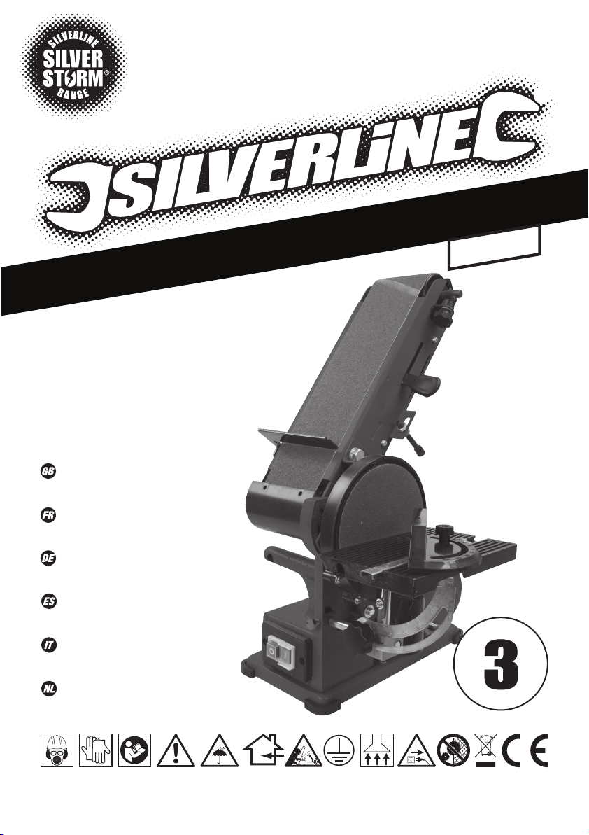
350W Bench Belt
972660
®
Disc Sander
390mm
350W Bench Belt
& Disc Sander
Ponceuse stationnaire
double 350 W
Band-und
Tellerschleifer, 350 W
Lijadora de banda
y disco, 350 W
350W levigatrice a
nastro e disco
350 W tafel band en
schijf schuurmachine
www.silverlinetools.com
A
R
U
A
G
N
R
A
E
Y
R
E
G
I
S
T
E
E
*
E
N
I
L
T
N
E
O
R
Page 2
1 2 3 4
21
20
19
18
17
5
6
7
8
9
101112
13141516
22 23 24 25 28 29 302726
35
34
33
31
32
2
Page 3

36 37 38
39
40
41
42
43
11 45 44
1
www.silverlinetools.com
3
Page 4
A
B
C
D
G
J
E
H
K
F
I
L
M
N
O
4
Page 5

&
350W Bench Belt
English .................. 6
Français ................ 12
Deutsch ................. 18
®
Disc Sander
390mm
Español ................. 24
Italiano .................. 30
Nederlands ............ 36
www.silverlinetools.com
5
Page 6
GB
Original Instructions
Description of Symbols
The rating plate on your tool may show symbols. These represent important information
about the product or instructions on its use.
Wear hearing protection
Wear eye protection
Wear breathing protection
Wear head protection
Wear hand protection
Read instruction Manual
Caution!
DO NOT use in rain or damp environments!
For indoors use only!
Be aware of kickback!
Class I construction (double insulated for additional protection)
Dust extraction required or recommended
Always disconnect from the power supply when adjusting, changing
accessories, cleaning, carrying out maintenance and when not in use!
Important safety devices! Ensure correct function, maintain in
accordance with instructions and DO NOT disable!
Environmental Protection
Waste electrical products should not be disposed of with household
waste. Please recycle where facilities exist. Check with your local
authority or retailer for recycling advice.
Conforms to relevant legislation and safety standards.
Technical Abbreviations Key
V Volts
A, mA Ampere, milli-Amp
n0 No load speed
° Degrees
Ø Diameter
Hz Hertz
W, kW Watt, kilowatt
-1
/min or min
dB(A) Decibel sound level (A weighted)
m/s2 Metres per second squared (vibration magnitude)
Operations per minute
Specification
Voltage: ................................................................................ 230-240V~, 50Hz
Power: ..................................................................................................... 350W
Duty Cycle: ...................................................... S2 30 minutes (short time duty)
No load speed - Sanding disc (n0): ....................................................1450min
Sanding disc size: ..............................................................................Ø150mm
Belt size: .......................................................... 914 x 100mm & 915 x 100mm
Belt table tilt angle: ..............................................................................0° - 90°
Belt surface area: ....................................................................... 390 x 100mm
Table size: .................................................................................. 390 x 125mm
Belt speed: ..................................................................... 282 m/min <4.7m/s>
Belt Sander Dust Port: .............................Ø40mm (external), Ø37mm (internal)
Sanding Disc Dust Port:...........................Ø40mm (external), Ø34mm (internal)
Table tilt: ................................................................................................. 0-45°
Protection class: ..........................................................................................
Ingress protection: .....................................................................................IP20
Power cord length: ...................................................................................... 2m
Dimensions (L x W x H):.....................................................500 x 265 x 305mm
Weight: ...................................................................................................15.5kg
As part of our ongoing product development, specifications of Silverline products
Sound and vibration information:
Sound Pressure LPA:..............................................................................77dB(A)
Sound Power LWA: ................................................................................ 90dB(A)
Uncertainty K: ............................................................................................ 3dB
Vibration: ...........................................................................................<2.5 m/s
The sound intensity level for the operator may exceed 85dB(A) and sound protection
WARNING: Always wear ear protection where the sound level exceeds 85dB(A) and
limit the time of exposure if necessary. If sound levels are uncomfortable, even with ear
protection, stop using the tool immediately and check the ear protection is correctly fitted
and provides the correct level of sound attenuation for the level of sound produced by
your tool.
WARNING: User exposure to tool vibration can result in loss of sense of touch, numbness,
tingling and reduced ability to grip. Long term exposure can lead to a chronic condition. If
necessary, limit the length of time exposed to vibration and use anti-vibration gloves. Do
not operate the tool with hands below a normal comfortable temperature, as vibration will
have a greater effect. Use the figures provided in the specification relating to vibration to
calculate the duration and frequency of operating the tool.
Sound and vibration levels in the specification are determined according to EN60745 or
similar international standards. The figures represent normal use for the tool in normal
working conditions. A poorly maintained, incorrectly assembled, or misused tool, may
produce increased levels of noise and vibration. www.osha.europa.eu provides information
on sound and vibration levels in the workplace that may be useful to domestic users who
use tools for long periods of time.
may alter without notice.
measures are necessary.
-1
2
6
Page 7

350W Bench Belt & Disc Sander972660
General Safety
WARNING! When using electric power tools, basic safety precautions should always be
followed to reduce the risk of fire, electric shock and personal injury including the following
safety information. Read all these instructions before attempting to operate this product
and save these instructions for future use.
WARNING: This appliance is not intended for use by persons (including children) with
reduced, physical or mental capabilities or lack of experience or knowledge unless they
have been given supervision or instruction concerning use of the appliance by a person
responsible for their safety. Children must be supervised to ensure that they do not play
with the appliance.
CAUTION: Use the power tool, accessories and tool bits etc. in accordance with these
instructions, taking into account the working conditions and the work to be performed. Use
of the power tool for operations different from those intended could result in a hazardous
situation.
The term "power tool" in the warnings refers to your mains-operated (corded) power tool
or battery-operated (cordless) power tool.
1 - Keep work area clear - Cluttered areas and benches invite injuries
2 - Consider work area environment
- Do not expose tools to rain
- Do not use tools in damp or wet locations
- Keep work area well lit
- Do not use tools in the presence of flammable liquids or gases
3 - Guard against electric shock - Avoid body contact with earthed or grounded
surfaces (e.g. pipes, radiators, ranges, refrigerators)
4 - Keep other persons away - Do not let persons, especially children, not involved in
the work touch the tool or the extension cord and keep them away from the work
area
5 - Store idle tools - When not in use, tools should be stored in a dry locked-up place,
out of reach of children
6 - Do not force the tool - It will perform the job better and safer at the rate for which it
was intended
7 - Use the right tool - Do not force small tools to do the job of a heavy duty tool
Do not use tools for purposes for which they are not intended; for example do not use
circular saws to cut tree limbs or logs
8 - Dress appropriately
- Do not wear loose clothing or jewellery, which can be caught in moving parts
- Suitable safety footwear is recommended when working outdoors.
- Wear protective covering to contain long hair
9 - Use protective equipment
-Use safety glasses
-Use face or dust mask if working operations create dust
WARNING: Not using protective equipment or appropriate clothing can cause personal
injury or increase the severity of an injury.
10 - Connect dust extraction equipment - If the tool is provided for the connection of
dust extraction and collecting equipment, ensure these are connected and properly
used
11 - Do not abuse the power cable - Never pull the power cable to disconnect it from the
socket. Keep the power cable away from heat, oil and sharp edges. Damaged or
entangled power cables increase the risk of electric shock
12 - Secure work - Where possible use clamps or a vice to hold the work. It is safer than
using your hands
13 - Do not overreach - Keep proper footing and balance a t all times
14 - Maintain tools with care
- Keeping cutting tools sharp and clean makes the tool easier to control and less
likely to bind or lock in the workpiece
- Follow instructions for lubricating and changing accessories
- Inspect tool power cables periodically and have them repaired by an authorised
service facility if damaged
- Inspect extension cables periodically and replace if damaged
- Keep handles dry, clean and free from oil and grease
WARNING: Many accidents are caused by poorly maintained power tools.
15 - Disconnect tools - Disconnect tools from the power supply when not in use, before
servicing, and when changing accessories such as blades, bits and cutters
WARNING: The use of accessories or attachments not recommended by the manufacturer
may result in a risk of injury to persons.
16 - Remove adjusting keys and wrenches - Form the habit of checking to see that
keys and adjusting wrenches are removed from the tool before switching it on
17 - Avoid unintentional starting - Ensure switch is in “off” position when connecting to
a mains socket, inserting a battery pack, or when picking up or carrying the tool
WARNING: Unintended starting of a tool can cause major injuries.
18 - Use outdoor extension leads - When the tool is used outdoors, use only extension
cords intended for outdoor use and so marked. Use of an extension cable suitable for
outdoor use reduces the risk of electric shock
19 - Stay alert
- Watch what you are doing, use common sense and do not operate the tool when you
are tired
- Do not use a power tool while you are under the influence of drugs, alcohol or
medication
WARNING: A moment of inattention while operating power tools may result in serious
personal injury.
20 - Check damaged parts
- Before further use of tool, it should be carefully checked to determine that it will
operate properly and perform its intended function
- Check for alignment of moving parts, binding of moving parts, breakage of parts,
mounting and any other conditions that may affect its operation
- A guard or other part that is damaged should be properly repaired or replaced by an
authorised service centre unless otherwise indicated in this instruction manual
- Have defective switches replaced by an authorised service centre
WARNING: Do not use the tool if the on/off switch does not switch it on and off. The switch
must be repaired before the tool is used.
21 - Have your tool repaired by a qualified person - This electric tool complies with the
relevant safety rules. Repairs should only be carried out by qualified persons,
otherwise this may result in considerable danger to the user
WARNING: When servicing use only identical replacement parts.
WARNING: If the power cable is damaged it must be replaced by the manufacturer or an
authorised service centre.
22 - Power tool mains plugs must match the mains socket - Never modify the plug in
any way. Do not use any adapter plugs with earthed (grounded) power tools.
Unmodified plugs and matching sockets will reduce risk of electric shock
23 - If operating a power tool outside use a residual current device (RCD) - Use of an
RCD reduces the risk of electric shock
NOTE: The term “residual current device (RCD)” may be replaced by the term “ground fault
circuit interrupter (GFCI)” or “earth leakage circuit breaker (ELCB)”.
WARNING: Before connecting a tool to a power source (mains switch power point
receptacle, outlet, etc.) be sure that the voltage supply is the same as that specified on
the nameplate of the tool. A power source with a voltage greater than that specified for
the tool can result in serious injury to the user, and damage to the tool. If in doubt, do not
plug in the tool. Using a power source with a voltage less than the nameplate rating is
harmful to the motor.
Sanding Tool Safety
WARNING!
• Hold the power tool by insulated handles or gripping surfaces only, because
the sanding belt/sheet may contact its own cord. Cutting a "live" wire may make
exposed metal parts of the power tool ‘live’ and could give the operator an electric
shock.
• Recommendation that the tool always be supplied via a residual current device
with a rated residual current of 30 mA or less.
• If the replacement of the supply cord is necessary, this has to be done by the
manufacturer or his agent in order to avoid a safety hazard.
a. ALWAYS wear appropriate protective equipment, including a dust mask with a
minimum FFP2 rating, eye protection and ear defenders
b. Ensure all people in the vicinity of the work area are also equipped with suitable
personal protective equipment
c. Take special care when sanding some woods (such as beech, oak, mahogany
and teak), as the dust produced is toxic and can cause extreme reactions
d. NEVER use to process any materials containing asbestos. Consult a qualified
professional, if you are uncertain whether an object contains asbestos
e. DO NOT sand magnesium or alloys containing a high percentage of magnesium
f. Be aware of paint finishes or treatments that may have been applied to the
material that is being sanded. Many treatments can create dust that is toxic,
or otherwise harmful. If working on a building constructed prior to 1960, there is an
increased chance of encountering lead-based paints
g. The dust produced when sanding lead-based paints is particularly hazardous to
children, pregnant women, and people with high blood pressure. DO NOT allow
these people near to the work area, even if wearing appropriate personal protective
equipment
www.silverlinetools.com
7
Page 8

GB
h. Whenever possible, use a vacuum dust extraction system to control dust and
waste
i. Be especially careful when using a machine for both wood and metal sanding.
Sparks from metal can easily ignite wood dust. ALWAYS clean your machine
thoroughly to reduce the risk of fire
j. Empty the dust bag or container (where applicable) frequently during use,
before taking breaks and after completion of sanding. Dust may be an explosion
hazard. DO NOT throw sanding dust into an open fire. Spontaneous combustion may
occur when oil or water particles come into contact with dust particles. Dispose of
waste materials carefully and in accordance with local laws and regulations.
k. Work surfaces and sandpaper can become very hot during use. If there is
evidence of burning (smoke or ash), from the work surface, stop and allow the
material to cool. DO NOT touch work surface or sandpaper until they have had time
to cool
l. DO NOT touch the moving sandpaper
m. ALWAYS switch off before you put the sander down
n. DO NOT use for wet sanding. Liquids entering the motor housing can cause severe
electric shocks
o. ALWAYS unplug the sander from the mains power supply before changing or
replacing sandpaper
p. Even when this tool is used as prescribed it is not possible to eliminate all
residual risk factors. If you are in any doubt as to safe use of this tool, do not use it
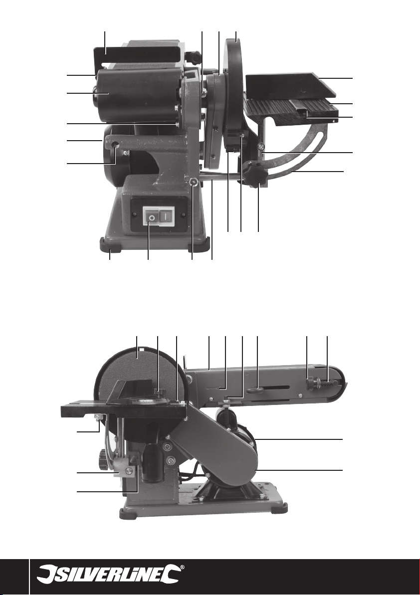
Product Familiarisation
1. Tool Rest
2. Belt Sander Angle Nut
3. Motor Belt Housing
4. Disc Enclosure
5. Mitre Guide
6. Table
7. Mitre Guide Channel
8. Table Angle Indicator
9. Table Angle Gauge
10. Table Angle Knob
11. Disc Sander Dust Extraction Assembly
12. Disc Dust Port
13. Table Rod
14. Table Mounting Bolt
15. On/Off Switch
16. Rubber Feet
17. Belt Table Mounting
18. Belt Table Mounting Bolt Thread
19. Belt Roller Cover Screws
20. Belt Roller Cover
21. Tool Rest Mounting
22. Sanding Disc
23. Mitre Guide Angle Knob
24. Mitre Angle Indicator
25. Sanding Belt
26. Direction Indicator
27. Sanding Belt Height Adjustment Nut
28. Belt Release Lever
29. Belt Tension Knob
30. Belt Tension Spring Mechanism
31. Motor
32. Motor Belt Spindle (under cover)
33. Disc Table Mounting
34. Table Block
35. Table Bolt
36. Tool Rest Spring Washer
37. Tool Rest Bolt
38. Tool Rest Washer
39. Disc Sander Dust Extraction Assembly Screws (x 4)
40. Disc Sander Dust Extraction Assembly Washers (x 4)
41. Disc Enclosure Fittings (x3)
42. Disc Enclosure Mounting Grub Screw
43. Hex Key
44. Sanding Disc Base
45. Hook & Loop Adhesive Pad
Intended Use
• Bench-mounted combined belt and disc sander. Suitable for sanding a wide range of
materials including metal, wood and plastic. Sanding applications depend on fitted
belt or disc type and grit level. Not suitable for sanding materials that may produce
toxic particles or that may be highly flammable or have other dangerous material
properties. Not suitable for sanding with liquids including water and oil. Not intended
for commercial or industrial use.
Unpacking Your Tool
• Carefully unpack and inspect your new tool. Familiarise yourself with all its features
and functions
• Ensure that all parts of the tool are present and in good condition. If any parts are
missing or damaged, have such parts replaced before attempting to use this tool
Before Use
WARNING: Ensure the tool is disconnected from the power supply before attaching
or changing any accessories, or making any adjustments.
Note: It is highly recommended it is only connected to a circuit protected by a RCD or used
with a plug-in RCD.
Note: This tool is earthed and must only be connected to mains with a earth connection. Do
not attempt to use it without an earth connection.
Bench Mounting
Note: It is recommended the tool is securely mounted to a strong, stable workbench
(fittings not supplied) once assembled.
• There are 2 suitable holes in the base of the tool. Ensure all bolts are a good match for
the bench-fitting holes of the tool.
Assembling
• Fit the 4 supplied Rubber Feet (15) to the base of the tool
8
Page 9

350W Bench Belt & Disc Sander972660
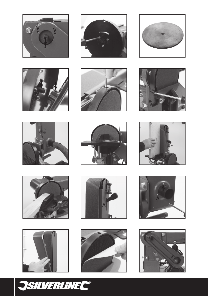
Sanding disc assembly
1. The Disc Enclosure (4) is secured to the tool with the Disc Enclosure Fittings (41) as
shown in Image A and B. Make sure the enclosure is fitted correctly with the four
screw threads horizontal at the bottom
2. Very carefully attach the Hook & Loop Adhesive Pad (45) to the Sanding Disc Base
(44 & image C). Ensure the Sanding Disc Base is completely clean of oil and grease.
Peel back the backing of the Hook & Loop Adhesive Pad and ensure they are lined up
perfectly before attaching
3. Fit the supplied Sanding Disc (22) to the hook & loop surface
4. Partially screw in the Disc Enclosure Mounting Grub Screw (42) into the thread at the
back of the Sanding Disc Base (44) then fit the Sanding Disc Base to the spindle as
shown in image D and E using the supplied Hex Key (43) as shown in Image D and E.
Use the slot at the top of the Disc Enclosure to access the Disc Enclosure Mounting
Grub Screw for tightening
5. Fit the Disc Sander Dust Extraction Assembly (11) using the Disc Sander Dust
Extraction Assembly Screws (39) and Disc Sander Dust Extraction Assembly Washers
(40)
Sanding belt section assembly
• The Tool Rest (1) is secured to the Tool Rest Mounting (21) using the Tool Rest Spring
Washer (36), Tool Rest Bolt (37) and Tool Rest Washer (38). Make sure the spring
washer is between the washer and bolt head
• The belt sander surface can be adjusted between horizontal and vertical 0-90° by
locking at the desired angle with the Belt Sander Angle Nut (2). The 0° height in the
horizontal position is adjusted with the Sanding Belt Height Adjustment Nut (27)
Changing the belt
Note: This should be read as part of the pre-operation check even if the belt is already
fitted.
1. Move the Belt Release Lever (28) forward as shown in image K
2. Remove the Belt Roller Cover (20) by removing the Belt Roller Cover Screws (19) and
the screws indicated in image L
3. Remove the screws indicated on image M and the screws on the far side in the same
positions and carefully pull the bottom metal plate away from the tool as shown in
image M
4. Carefully remove the existing belt noting the direction arrow on the rear of the belt
5. Fit the new belt ensuring the direction of the belt is correct as shown by the Direction
Indicator (26)
6. Refit the plate, screws and Belt Roller Cover
Note: Belt tracking and overall belt tension is controlled by the Belt Tension Knob (29).
Adjustment can be made by applying more or less tension to the Belt Tension Spring
Mechanism (30). This should not be necessary in normal use but may be necessary if the
belt is incorrectly tracking, slipping or the belt is excessively tensioned.
Attaching the Table
Note: The Table (6) can be positioned to either work with the Disc Sander or Belt Sander
as shown in images I and J. The horizontal plane of the Table can be adjusted but there is
no gauge built in for indicating this angle. An additional tool will be required to measure.
The Table angle can be adjusted on 3 axes to allow for the workpiece to be sanded at
any angle.
1. To use the Table with Disc Sander, insert the Table Rod (13) into the Disc Table
Mounting (33) and secure by tightening the Table Mounting Bolt (14). To use with the
Belt Sander move the Table Mounting Bolt to the Belt Table Mounting Bolt Thread (18)
and use the Belt Table Mounting (17)
2. Additional adjustments for Table Rod length and some other minor adjustments are
available on the Table Block (34) and below the Table surface using the supplied Hex
Key
3. The Mitre Guide (5) slots into the Mitre Guide Channel (7) as shown: it is locked into
the required position by tightening the Mitre Guide Angle Knob (23) and the angle is
indicated by the Mitre Angle Indicator (24)
Dust Extraction
Note: Both the Disc Sander and Belt Sander have dust extraction ports. It is highly
recommended that dust extraction is used with this tool. The hose can be connected to
which ever tool is being used at the time but a flexible ‘Y’ hose is recommended so both
are simultaneously connected for safety and more convenience to the operator.
1. For the Disc Sander connect the hose of the dust extraction system or vacuum cleaner
to the Disc Dust Port (12)
2. For the Belt Sander connect to the dust port as shown in image G. Allow some
additional slack in the hose connection due to angle of the belt sander varying
Pre-operational checks
• Always check that all parts or a ttachments are secure, and that rotating parts will not
contact guards or machine case
Operation
WARNING: Always wear suitable personal protective equipment, including eye,
hearing and respiratory protection, when operating this machine.
WARNING: Be aware that the cast metal motor housing may get hot during use.
WARNING: This tool is only suitable for one operator at a time and is designed so that a
load is applied to one side only at a time.
<exclamation triangle>Duty cycle: Do not exceed a maximum operating time of 20
minutes in every hour. It is recommended to keep to an operating time of no more than 10
minutes to reduce risk of damage to the tool from over-heating.
IMPORTANT: Fine particles of dust are created when grinding and sanding, some particles
should not be inhaled or contact skin plus there is also the risk of fine metal particles
damaging electrical tools if they enter vents. It is recommended dust extraction is used in
the workshop where this tool is fitted. If this is not possible, regularly clean and vacuum the
work area around the tool.
Switching on and off
Note: Do not switch the machine on or off when under load. Always allow the motor
to reach its full speed before applying a load, and to stop completely before leaving
unattended.
• To switch the machine on, press the ‘I’ on the On/Off Switch (15)
• To switch the machine off, press the ‘O’ on the On/Off Switch
Sanding
• Always apply the workpiece to the left of centre of the disc to prevent kickback
• Always hold the work with both hands and never allow fingers to get close to the
abrasive surface
• Move the workpiece across the sanding surface as you sand to prevent uneven wear
of the belt or disc
• Small workpieces are far more likely to cause injury. They bring fingers closer to the
abrasive surface and are more likely to be propelled towards the operator to cause
injury. Use extra caution
• Do not apply additional pressure when sanding. This will cause additional wear to the
belt, disc, drive belt and motor. In some instances it could cause the sanding belt to
snap which could injure the operator
• Contour sanding can be done on the end roller of the sanding belt section. Normally
the sanding belt section would be in the vertical position to do this
• Keep the distance between the sanding surface and the edge of the Table to
approximately 1.6mm. This will vary as you adjust the table to different angles. There
are multiple grub screws and other knobs that can be made to keep adjusting this
distance to the correct value
Accessories
• A range of accessories and consumables including an 80 grit sanding belt (186813)
is available from your Silverline stockist. Spare parts can be obtained from
toolsparesonline.com
Maintenance
WARNING: ALWAYS disconnect from the power supply before carrying out any
inspection, maintenance or cleaning.
Changing the sanding disc
1. Remove the table assembly from the front of the sanding disc
2. Remove the 4 screws of the Disc Sander Dust Extraction Assembly (11) and remove. If
fitted, remove the vacuum hose if necessary
3. Carefully remove the existing worn hook & loop sanding sheet as shown in image N.
As you peel it away from the hook and loop surface secure the hook and loop surface
attached to the Sanding Disc Base (44) to prevent the adhesive backing from coming
away from the surface
4. Carefully fit the new sanding disc ensuring it is correctly centralised
5. Refit the Disc Sander Dust Extraction Assembly and re-attach the vacuum hose
6. Do a test run to ensure the disc is operating normally
7. Refit the Table if required
Motor Belt Replacement
1. Remove the Table (6) from the front of the Sanding Disc (22)
2. Remove the 4 screws of the Disc Sander Dust Extraction Assembly (11) and remove
3. Unscrew the Disc Enclosure Mounting Grub Screw (42) with the supplied Hex Key (43)
and remove the Sanding Disc Base (44)
4. Remove the 3 screws that secure the Disc Enclosure (4) to the tool
5. Remove the screws on the side of the Motor Belt Housing and carefully pull the cover
of the Motor Belt Housing off (image O)
6. Check the belt specification marked on the worn belt matches that of the new belt
before fitting
www.silverlinetools.com
9
Page 10
GB
7. Carefully slide off the worn drive belt from the Motor Belt Spindle (32) gear and
remove by lifting away from the top gear
8. Fit the new belt over the top gear first before then sliding onto the Motor Belt Spindle
gear
9. Refit all parts in the reverse order ensuring all parts are correctly tightened and
checking your work at every stage
10. Check the belt is operating properly by doing a test without applying a load to the tool
General inspection
• Regularly check that all the fixing screws are tight
• Inspect the supply cord of the tool, prior to each use, for damage or wear. Repairs
should be carried out by an authorised Silverline service centre. This advice also
applies to extension cords used with this tool
Cleaning
• Keep your tool clean at all times. Dirt and dust will cause internal parts to wear quickly,
and shorten the machine’s service life. Clean the body of your machine with a soft
brush, or dry cloth. If available, use clean, dry, compressed air to blow through the
ventilation holes
• Clean the tool casing with a soft damp cloth using a mild detergent. Do not use
alcohol, petrol or strong cleaning agents
• Never use caustic agents to clean plastic parts
Storage
• Unplug this tool from the mains and ensure the workshop or garage is locked to
prevent access by children when not in use
Disposal
Always adhere to national regulations when disposing of power tools that are no longer
functional and are not viable for repair.
• Do not dispose of power tools, or other waste electrical and electronic equipment
(WEEE), with household waste
• Contact your local waste disposal authority for information on the correct way to
dispose of power tools
Troubleshooting
Problem Possible cause Solution
Machine will not start
Excessive vibration when in use
Sanding belt does not run evenly it goes left or right
‘Squealing’ sound whilst sanding Belt slipping See ‘Changing the belt’ for tension adjustment
Sanding belt slows down when sanding
Wood burns while sanding Sanding belt worn or clogged with sap Replace belt
Motor housing getting excessively hot Duty cycle not being followed
Unexpected noise from the tool
Circuit breaker tripped Reset circuit breaker
Tool fault
Wheel loose Turn off immediately and re-tighten wheel fittings
Tool not fully secured to workbench Check and tighten bolts and fittings
Tool has been directly bolted to metal workbench or rubber
feet missing or damaged
Tool incorrectly set See ‘Changing the belt’ section
Worn or incorrectly made belt Replace belt
Belt tension too high See ‘Changing the belt’ for tension adjustment
Applying too much pressure to workpiece Reduce pressure
This is a high vibration tool and fittings can work loose
over time
Worn internal parts or other fault Contact an authorised service centre
Have the tool serviced by an authorised Silverline service
centre
Fit a vibration-reducing material between the tool and
the workbench surface. A small piece of wood would be
satisfactory
Ensure the duty cycle is followed with a maximum of 30
minutes use per hour. If the tool still gets excessively hot
allow further cooling time as other factors including ambient
temperature may increase the required cooling time. Running
the tool well within the duty cycle may increase the working
life of the tool
Check all fittings are correctly tightened. If any fittings are
repeatedly becoming loose check the fittings order is correct
and add spring washers or lock nuts if necessary
10
Page 11

Silverline Tools Guarantee
This Silverline product comes with a 3 year guarantee
Register this product at www.silverlinetools.com within 30 days of purchase in order to
qualify for the 3 year guarantee. Guarantee period begins according to the date of purchase
on your sales receipt.
Terms & Conditions
Guarantee period becomes effective from the date of retail purchase as detailed on your
sales receipt.
PLEASE KEEP YOUR SALES RECEIPT
If this product develops a fault within 30 days of purchase, return it to the stockist where it
was purchased, with your receipt, stating details of the fault. You will receive a replacement
or refund.
If this product develops a fault after the 30 day period, return it to:
Silverline Tools Service Centre
PO Box 2988
Yeovil
BA21 1WU, UK
The guarantee claim must be submitted during the guarantee period.
You must provide the original sales receipt indicating the purchase date, your name, address
and place of purchase before any work can be
carried out.
You must provide precise details of the fault requiring correction.
Claims made within the guarantee period will be verified by Silverline Tools to establish if the
deficiencies are related to material or manufacturing of the product.
Carriage will not be refunded. Items for return must be in a suitably clean and safe state for
repair, and should be packaged carefully to prevent damage or injury during transportation.
We may reject unsuitable or
unsafe deliveries.
All work will be carried out by Silverline Tools or its authorized
repair agents.
The repair or replacement of the product will not extend the period
of guarantee
Defects recognised by us as being covered by the guarantee shall be corrected by means of
repair of the tool, free of charge (excluding carriage charges) or by replacement with a tool
in perfect working order.
Retained tools, or parts, for which a replacement has been issued, will become the property
of Silverline Tools.
The repair or replacement of your product under guarantee provides benefits which are
additional to and do not affect your statutory rights as a consumer.
350W Bench Belt & Disc Sander972660
Registering your purchase
Registration is made at silverlinetools.com by selecting the Guarantee Registration button.
You will need to enter:-
• Your personal details
• Details of the product and purchase information
Once this information is entered your guarantee certificate will be created in PDF format for
you to print out and keep with your purchase.
What is covered:
The repair of the product, if it can be verified to the satisfaction of Silverline Tools that the
deficiencies were due to faulty materials or workmanship within the guarantee period.
If any part is no longer available or out of manufacture, Silverline Tools will replace it with a
functional replacement part.
Use of this product in the EU.
What is not covered:
Silverline Tools does not guarantee repairs required as a result of:
Normal wear and tear caused by use in accordance with the operating instructions eg
blades, brushes, belts, bulbs, batteries etc.
The replacement of any provided accessories drill bits, blades, sanding sheets, cutting discs
and other related items.
Accidental damage, faults caused by negligent use or care, misuse, neglect, careless
operation or handling of the product.
Use of the product for anything other than normal domestic purposes.
Change or modification of the product in any way.
Use of parts and accessories which are not genuine Silverline Tools components.
Faulty installation (except installed by Silverline Tools).
Repairs or alterations carried out by parties other than Silverline Tools or its authorized
repair agents.
Claims other than the right to correction of faults on the tool named in these guarantee
conditions are not covered by the guarantee.
Battery Guarantee
Silverline batteries are guaranteed for 30 days. If a defect occurs on a registered battery
during the term of the Battery Guarantee, due to material or manufacturing fault, then
Silverline will replace it free of charge. This guarantee does not apply to commercial use nor
does it extend to normal wear and tear or damage as a result of accident, abuse or misuse.
CE Declaration of Conformity
The undersigned: Mr Darrell Morris
as authorised by: Silverline Tools
Declares that
Identification code: 972660
Description: 350W Bench Belt & Disc Sander
Conforms to the following directives and standards:
• Machinery Directive 2006/42/EC
• Low Voltage Directive 2006/95/EC
• EMC Directive 2004/108/EC
• RoHS Directive 2011/65/EU
• EN61029-1+A11:2010
• EN55014-1+A1:2009
• EN55014-2+A2:2008
• EN61000-3-2+A2:2009
• EN61000-3-3:2008
Notified body: TÜV SÜD Product Service
The technical documentation is kept by: Silverline Tools
Date: 25/02/15
Signed:
Mr Darrell Morris
Managing Director
Name and address of the manufacturer:
Powerbox International Limited, Company No. 06897059. Registered address: Central House,
Church Street, Yeovil, Somerset BA20 1HH, United Kingdom.
www.silverlinetools.com
11
Page 12
FR
Traductions des instructions originales
Description des symboles
La plaque signalétique figurant sur votre outil peut présenter des symboles. Ces
symboles constituent des informations importantes relatives au produit ou des
instructions concernant son utilisation.
Port de protection auditive
Port de lunettes de sécurité
Port du masque respiratoire
Port du casque
Port de gants
Lire le manuel d’instructions
Attention !
NE PAS utiliser sous la pluie ou dans un environnement humide !
Pour usage intérieur uniquement
Attention à l’effet de rebond !
Construction de classe I (Mise à la terre)
Système d’extraction de la poussière requis ou recommandé
Débranchez toujours l’appareil avant d’effectuer un réglage, de changer
d’accessoire, de le nettoyer, de l’entretenir, ou lorsqu’il n’est plus utilisé.
Importants dispositifs de sécurité ! Vérifier leur bon fonctionnement et
leur bon état conformément aux instructions, et NE PAS désactiver !
Protection de l’environnement
Les produits électriques usagés ne doivent pas être jetés avec les
ordures ménagères. Veuillez les recycler dans les centres prévus à
cet effet. Pour de plus amples informations, veuillez contacter votre
municipalité ou point de vente.
Conforme à la réglementation et aux normes de sécurité pertinentes
Légende des abréviations
techniques
V Volts
A, mA Ampère, milliampère
n0 Vitesse à vide
° Degrés
Ø Diamètre
Hz Hertz
W, kW Watt, kilowatt
-1
/min or min
dB(A) Niveau acoustique en décibels (pondérés A)
m/s2 Mètres par seconde carrée (mesure vibratoire)
Opérations par minute
Caractéristiques techniques
Tension : .............................................................................230-240 V~, 50 Hz
Puissance : .............................................................................................350 W
Cycle de service : ................................................... S2 30 minutes (cycle court)
Vitesse à vide – disque de ponçage (n0) : ........................................1450 min
Dimensions du disque de ponçage : .......................................................Ø 150
Dimensions de la bande de ponçage :........... 914 x 100 mm et 915 x 100 mm
Inclinaison de la table de ponçage sur bande : .....................................0° - 90°
Surface de la bande : ................................................................ 390 x 100 mm
Dimensions de la table : ............................................................ 390 x 125 mm
Vitesse de la bande : ..................................................... 282 m/min <4,7 m/s>
Orifice d’extraction – bande : ................. Ø40 mm (externe), Ø37 mm (interne)
Orifice d’extraction – disque : ................ Ø40 mm (externe), Ø34 mm (interne)
Inclinaison de la table : ............................................................................ 0-45°
Classe de protection : ..................................................................................
Indice de protection :..................................................................................IP20
Longueur du câble d’alimentation : ............................................................ 2 m
Dimensions (L x l x H) : .....................................................500 x 265 x 305 mm
Poids : .....................................................................................................5,5 kg
Du fait de l’évolution constante de nos produits, les caractéristiques des produits
Silverline peuvent changer sans notification préalable.
Informations sur le niveau d’intensité sonore et vibratoire :
Pression acoustique LPA : .....................................................................77 dB(A)
Puissance acoustique LWA : ..................................................................90 dB(A)
Incertitude K : ............................................................................................ 3 dB
Vibration : ..........................................................................................<2,5 m/s
L’intensité sonore peut dépasser 85 dB(A) et il est recommandé que l’opérateur
AVERTISSEMENT : Portez toujours des protections sonores lorsque le niveau d’intensité
est supérieur à 85 dB(A) et limitez le temps d’exposition si nécessaire. Si l’intensité
sonore devient inconfortable, même avec les protections, arrêtez immédiatement d’utiliser
l’appareil, vérifiez que les protections sont bien en place et adaptées au niveau sonore
produit par l’appareil.
AVERTISSEMENT : L’exposition de l’utilisateur aux vibrations peut engendrer une perte du
toucher, des engourdissements, des picotements et ainsi réduire la capacité de préhension.
De longues expositions peuvent également provoquer des pathologies chroniques. Si
nécessaire, limitez le temps d’exposition aux vibrations et portez des gants anti-vibrations.
N’utilisez pas cet appareil lorsque la température de vos mains est en dessous des
températures normales, car l’effet vibratoire en est accentué. Référez-vous aux indications
chiffrées relatives aux vibrations qui sont mentionnées dans les caractéristiques
techniques pour calculer le temps et la fréquence d’utilisation de l’appareil.
Les niveaux sonores et vibratoires des caractéristiques techniques sont déterminés
conformément à la norme EN60745 ou aux normes internationales similaires. Ces
données correspondent à un usage normal de l’appareil, et ce dans des conditions de
travail normales. Un appareil mal entretenu, mal assemblé ou mal utilisé peut augmenter
les niveaux sonores et vibratoires. Pour plus d’informations sur les émissions sonores et
vibratoires, visitez le site http://osha.europa.eu/fr.
prenne des mesures de protection sonore.
-1
2
Consignes générales de
sécurité relatives aux appareils
électriques
AVERTISSEMENT ! Certaines précautions fondamentales, dont les consignes ci-dessous,
doivent impérativement être respectées lors de l’emploi d’outils électriques afin de réduire
le risque d’incendie, de choc électrique et de blessures corporelles. Veuillez lire l’intégralité
de ces consignes avant de mettre en marche ce produit et veuillez les conserver pour toute
consultation ultérieure.
AVERTISSEMENT : Cet appareil n’est pas conçu pour être utilisé par des personnes (y
compris les enfants) ayant des capacités physiques ou mentales réduites, ou n’ayant pas la
connaissance ou l’expérience requise, à moins d’être sous la supervision d’une personne
responsable de leur sécurité ou d’avoir reçu les instructions nécessaires. Les enfants ne
doivent pas jouer avec cet appareil.
12
Page 13

Ponceuse stationnaire double 350 W972660
ATTENTION : Utiliser l’appareil électrique, les accessoires et outils à monter conformément
à ces instructions, en tenant compte des conditions de travail et de la tâche à réaliser.
Toute utilisation d’un appareil électrique autre que celle pour laquelle il a été conçu peut
entraîner des situations à risque.
L’expression « appareil électrique » employée dans les présentes consignes recouvre aussi
bien les appareils filaires à brancher sur le secteur que les appareils sans fil fonctionnant
sous batterie.
1. Maintenir une zone de travail propre. Des zones encombrées et mal éclairées sont
sources d’accidents.
2. Prendre en compte la zone de travail :
- Ne pas exposer les outils à la pluie,
- Ne pas utiliser les outils dans des endroits humides,
- Travailler dans une zone bien éclairée,
- Ne pas utiliser d’outils électriques dans des environnements explosifs, tels qu’à
proximité de liquides, de gaz ou de poussières inflammables.
3. Éviter les décharges électriques. Éviter le contact corporel avec les surfaces mises à
la terre telles que tuyaux, radiateurs, cuisinières et réfrigérateurs.
4. Éloigner les personnes aux alentours. Ne laisser aucune personne dont la présence
n’est pas nécessaire, surtout les enfants, s’approcher de la zone de travail ou venir en
contact avec l’appareil.
5. Ranger les appareils électriques inutilisés dans un endroit sûr, sec et hors de portée
des enfants.
6. Ne pas forcer sur l’appareil électrique. Un appareil électrique adapté et employé au
rythme pour lequel il a été conçu permettra de réaliser un travail de meilleure qualité et
dans de meilleures conditions de sécurité
7. Utiliser l’appareil électrique approprié au travail à effectuer. Ne pas utiliser de
petits outils pour des tâches lourdes. N’utilisez pas l’outil pour une tâche pour laquelle
il n’a pas été prévu ; par exemple n’employez pas une scie circulaire pour couper une
branche d’arbre ou fendre des bûches.
8. Porter des vêtements appropriés.
- Ne pas porter de vêtements amples ou des bijoux pendants qui peuvent être happés
par les pièces en rotation.
- Le port de chaussures antidérapantes est recommandé en extérieur.
- Attacher ou protéger les cheveux longs.
9. Porter un équipement de protection approprié.
- Porter une protection oculaire.
- Porter un masque à poussières lors de travaux créant de la poussière.
AVERTISSEMENT : Ne pas porter d’équipements de protection ou de vêtements appropriés
peut engendrer et aggraver des blessures.
10. Brancher un système d’extraction de la poussière : si l’appareil est pourvu de
dispositifs destinés au raccord d’équipements d’extraction et de récupération de la
poussière/sciure, s’assurer qu’ils soient bien fixés et utilisés correctement.
11. Ne pas maltraiter le cordon électrique. Ne jamais utiliser le cordon électrique pour
porter, tirer ou débrancher l’appareil. Protéger le cordon électrique de la chaleur, du
contact avec l’essence, des bords tranchants et pièces rotatives. Un cordon électrique
endommagé ou entortillé accroît le risque de décharge électrique.
12. Immobiliser votre travail. Si possible, utiliser des serre-joints ou un étau pour
maintenir la pièce de travail. Cela offre davantage de sécurité que de tenir la pièce
avec la main.
13. Ne pas essayer d’atteindre une zone hors de portée. Se tenir toujours en position
stable permettant de conserver l’équilibre.
14. Veiller à l’entretien des appareils électriques.
- Veiller à ce que les outils de coupe soient tenus affûtés et propres, ce qui favorise leur
maîtrise et leur bon fonctionnement.
-Suivre les instructions de lubrification et de changement des accessoires.
-Vérifier régulièrement les câbles et les faire réparer/remplacer par un centre agrée.
-Vérifier également l’état des rallonges utilisées.
-Tenir les poignées de l’appareil propres (sans graisse ni huile) et sèches.
AVERTISSEMENT : de nombreux accidents sont dus à l’utilisation d’appareils électriques
mal entretenus.
15. Débrancher l’appareil électrique. Lorsque l’appareil n’est pas utilisé, ou avant tout
opération d’entretien ou de changement d’accessoires, veiller à débrancher l’appareil
de sa source d’alimentation.
AVERTISSEMENT : utiliser des accessoires non recommandés par le fabricant peut
engendrer des blessures.
16. Enlever les clés et outils de réglage. Prendre l’habitude de retirer ces outils avant de
mettre l’appareil en marche.
17. Éviter tout démarrage accidentel ou intempestif. S’assurer que l’interrupteur
marche-arrêt soit en position d’arrêt avant de brancher l’appareil sur l’alimentation
secteur ou d’installer la batterie, de prendre l’appareil ou de le transporter.
AVERTISSEMENT : les démarrages accidentels peuvent être dangereux.
18. Usage en extérieur : lors d’une utilisation de l’appareil électrique en extérieur, se
servir d’une rallonge appropriée à une utilisation en extérieur. Cela réduit le risque de
décharge électrique.
19. Rester vigilant.
- Faire preuve de bon sens lors de la manipulation de l’appareil.
- Ne pas utiliser un appareil électrique lorsque l’on se trouve dans un état de fatigue,
ou sous l’influence de drogues, d’alcool ou de médicaments.
AVERTISSEMENT : un moment d’inattention pendant l’utilisation d’un outil électrique peut
se traduire par des blessures graves.
20. Inspecter les pièces endommagées
- Avant d’utiliser un appareil, toujours vérifier qu’il soit en bon état de marche.
- Vérifier que les éléments rotatifs soient bien alignés et non grippés. S’assurer
de l’absence de pièces cassées ou endommagées susceptibles de nuire au bon
fonctionnement de l'appareil.
- Une protection ou partie défectueuse doit être réparée ou remplacée par un centre
agrée, sauf en cas d’indication contraire dans le manuel.
- Les interrupteurs défectueux doivent être remplacés par un centre agréé.
AVERTISSEMENT : ne pas utiliser un appareil électrique dont la commande ne s’effectue
plus par l’interrupteur marche-arrêt. Il est dangereux et doit être réparé.
21. Ne faire réparer votre appareil électrique que par un réparateur qualifié. Cet
appareil est conforme aux normes de sécurité en vigueur. Toute réparation doit être
effectuée par une personne qualifiée afin de garantir la sécurité de l’utilisateur.
AVERTISSEMENT : utiliser uniquement des pièces de rechange identiques.
AVERTISSEMENT : si le câble d’alimentation est endommagé, le faire remplacer par un
centre agréé.
22. La prise d’un appareil électrique doit être adaptée à la prise du secteur. Ne jamais
modifier la prise en aucune façon. Ne jamais utiliser d’adaptateur sur la prise
électrique d’appareils mis à la terre. Des prises non modifiées, adaptées aux boîtiers
de prise de courant, réduiront le risque de décharge électrique.
23. En cas d’utilisation en extérieur, utiliser une alimentation protégée par un
disjoncteur différentiel. L’utilisation d’un disjoncteur différentiel réduit le risque de
décharge électrique.
AVERTISSEMENT : Avant de brancher un appareil sur une source d’alimentation (prise
secteur, groupe électrogène, etc.) assurez-vous que la tension fournie soit la même que
celle spécifiée sur la plaque de l’appareil. Une source d’alimentation délivrant une tension
supérieure à celle indiquée sur l’appareil peut engendrer de sérieuses blessures pour
l’utilisateur et endommager l’appareil. En cas de doute, ne branchez pas l’appareil. Une
source d’alimentation délivrant une tension inférieure à celle indiquée sur l’appareil est
néfaste pour le moteur.
Consignes de sécurité relatives
aux outils de ponçage
AVERTISSEMENT !
• Tenez l’outil électrique uniquement par ses poignées ou surfaces de préhension
isolées, en effet, la bande ou la feuille abrasive pourrait entrer en contact avec
le câble d’alimentation de l’appareil. La coupure du câble sous tension pourrait
mettre l’appareil sous tension et occasionner un choc électrique chez l’utilisateur.
• Il est fortement recommandé d’alimenter l’appareil par le biais d’un disjoncteur
différentiel dont le courant résiduel nominal est de 30 mA ou moins.
• S’il est nécessaire de remplacer le cordon d’alimentation, cela doit être fait par
le fabricant ou un de ses agents agréés pour éviter tout danger.
a) Portez TOUJOURS des équipements de sécurité appropriés, parmi lesquels
un masque anti-poussières d’une protection minimale FFP2, des lunettes de
sécurité et un casque anti-bruit.
b) Il vous appartient de veiller à ce que les personnes se trouvant à proximité
de votre zone de travail soient également protégées par des équipements
adéquats.
c) Prenez des précautions particulières lors du ponçage de certaines essences de
bois (le hêtre, le chêne, l’acajou et le teck, par exemple) car la poussière produite
est toxique et peut provoquer des réactions aiguës chez certaines personnes.
d) Ne vous servez jamais de cet outil pour travailler sur des matériaux contenant
de l’amiante. Consultez un professionnel qualifié si vous ne savez pas si un objet
contient de l’amiante.
e) Ne poncez pas le magnésium ni les alliages qui en contiennent une proportion
élevée.
f) Tenez compte des peintures de finition et des traitements qui peuvent avoir été
appliqués sur la matière à poncer. De nombreux traitements peuvent produire
une poussière toxique ou dangereuse pour la santé. Si vous travaillez dans un
bâtiment dont la construction est antérieure à 1960, sachez que la présence de
peintures à base de plomb est fort probable.
g) La poussière produite par le ponçage des peintures à base de plomb est
particulièrement dangereuse pour les enfants, les femmes enceintes et les
personnes atteintes d’hypertension. Assurez-vous que ces personnes se tiennent
à l’écart de la zone de travail, même si elles portent un équipement de protection
adéquat.
www.silverlinetools.com
13
Page 14
FR
h) Dans la mesure du possible, employez un système d’extraction des poussières
pour mieux contrôler la dispersion des poussières.
i) Observez la plus grande prudence lors de l’utilisation d’un même appareil pour
poncer le bois et le métal. Les étincelles du métal peuvent aisément enflammer
les poussières de bois. Nettoyez TOUJOURS l’outil complètement pour réduire le
risque d’incendie.
j) Videz régulièrement le sac ou bac à poussière durant l’utilisation, avant de
prendre une pause et après avoir fini de poncer. La poussière peut représenter
un risque d’explosion. N’incinérez pas la poussière de ponçage. Une combustion
spontanée peut se produire lorsque des particules d’huile ou d’eau entrent en
contact avec les particules de poussière. Éliminez les déchets de ponçage avec
précaution et conformément aux lois et régulations locales.
k) Les surfaces de travail et le papier abrasif peuvent atteindre des températures
très élevées au cours du travail ; en cas de signe de combustion (fumée ou
cendre) de la surface de travail, arrêtez l’opération en cours et attendez que le
matériel refroidisse. Ne touchez pas la surface de travail ni le papier abrasif avant
qu’ils n’aient eu le temps de refroidir.
l) Ne touchez pas la feuille de ponçage lorsqu’elle est en mouvement.
m) Éteignez toujours l’appareil avant de le déposer.
n) Ne vous servez pas de cet outil pour le ponçage humide. Les liquides qui entrent
dans le boîtier moteur peuvent causer des chocs électriques graves.
o) Débranchez toujours l’appareil avant de procéder au changement ou à
l’installation d’un accessoire.
p) Même lorsque l’outil est utilisé comme indiqué, il est impossible d’éliminer tous
les facteurs de risque résiduels. Si vous avez des doutes quant à la manière sûre et
correcte de procéder, il est recommandé de ne pas utiliser cet outil
Familiarisation avec le produit
1. Porte-outil
2. Écrou d’inclinaison de la bande
3. Carter de la courroie moteur
4. Carter du disque de ponçage
5. Guide à biseau
6. Table
7. Coulisse du guide à biseau
8. Indicateur d’inclinaison de la table
9. Jauge d’inclinaison de la table
10. Bouton d’inclinaison de la table
11. Ensemble d’extraction des poussières du disque
12. Orifice d’extraction des poussières du disque
13. Barre de la table
14. Boulon de fixation de la table
15. Interrupteur marche/arrêt
16. Pieds en caoutchouc
17. Position de fixation de la table pour ponçage à bande
18. Taraudage pour boulon de fixation de la table
19. Vis du carter du rouleau de la bande
20. Carter du rouleau de la bande
21. Position de fixation du porte-outil
22. Disque de ponçage
23. Bouton d’inclinaison du guide à biseau
24. Indicateur de l’angle de biseau
25. Bande de ponçage
26. Indicateur d’avancée
27. Écrou de réglage de la hauteur de la bande
28. Levier de dégagement de la bande
29. Bouton tendeur de la bande
30. Mécanisme à ressort de tension de la bande
31. Moteur
32. Arbre de la courroie moteur (sous le carter)
33. Position de fixation de la table pour ponçage à disque
34. Dispositif de blocage de table
35. Boulon de table
36. Rondelle à ressort du porte-outil
37. Boulon du porte-outil
38. Rondelle du porte-outil
Vis de l’ensemble d’extraction des poussières du
39.
disque (x 4)
Rondelles de l’ensemble d’extraction des poussières
40.
du disque (x 4)
41. Fixations du carter du disque de ponçage (x3)
42. Vis sans tête du carter du disque de ponçage
43. Clé 6 pans
44. Support du disque de ponçage
45. Support autoagrippant à revers adhésif
Usage conforme
• Ponceuse stationnaire associant ponçage sur bande et ponçage sur disque. La
ponceuse est adaptée à une grande diversité de matériaux tels que le métal, le bois
et le plastique. Les applications de ponçage dépendront du type de bande ou de
disque utilisé et de son grain. Cet appareil n’est pas conçu pour meuler des matériaux
susceptibles de produire des particules toxiques, des matériaux inflammables ou
présentant d’autres propriétés dangereuses. Il n’est pas conçu pour un ponçage avec
des liquides tels que l’eau et l’huile. Il n’est pas destiné à des fins commerciales ou
industrielles.
Déballage
• Déballez le produit avec soin. Veillez à retirer tous les matériaux d’emballage et
familiarisez-vous avec toutes les caractéristiques du produit.
• Si des pièces sont endommagées ou manquantes, faites-les réparer ou remplacer avant
d’utiliser l’appareil.
Avant l’utilisation
AVERTISSEMENT : Débranchez TOUJOURS l’appareil avant d’effectuer une
inspection, son entretien ou son nettoyage.
Remarque : Il est vivement recommandé de ne brancher l’appareil que sur un circuit
protégé par un disjoncteur différentiel ou de le pourvoir d’un disjoncteur différentiel séparé.
Remarque : Cet outil dispose d’une mise à la terre et ne doit être connecté que sur un
circuit secteur protégé par mise à la terre. Ne pas l’employer sur tout autre type de circuit.
Installation sur l’établi
Remarque : Cet appareil doit être solidement monté sur un établi stable et solide (fixations
non fournies) une fois assemblé.
• Deux trous de boulonnage sont présents sur la base de la machine. S’assurer que tous
les boulons correspondent bien avec ces trous de boulonnage.
Assemblage
• Montez les 4 pieds en caoutchouc (15) fournis sur la base de l’appareil.
14
Page 15

Ponceuse stationnaire double 350 W972660
Assemblage du disque de ponçage
1. Le carter du disque de ponçage (4) est fixé sur l’appareil au moyen des fixations du
carter du disque de ponçage (41) illustrées sur les Images A et B. Assurez-vous que le
carter du disque soit bien installé et soit bien horizontal.
2. Fixez très soigneusement le support autoagrippant (45) sur le support du disque de
ponçage (44 + Image C). Vérifiez que le support du disque de ponçage soit exempt de
toute huile ou graisse. Décollez l’étiquette du dos du support autoagrippant fixez ce
dernier sur le support (44) en le centrant bien.
3. Installez le disque de ponçage (22) sur la surface autoagrippante.
4. Vissez partiellement la vis sans tête du carter du disque de ponçage (42) dans le
taraudage présent sur le dos du support du disque de ponçage (44) puis installez le
support du disque de ponçage sur l’arbre, de la manière indiquée sur les images D
et E au moyen de la clé 6 pans (43). Servez-vous de la fente située sur le haut du
carter du disque de ponçage afin d’accéder à la vis sans tête du carter du disque de
ponçage et pour la serrer.
5. Montez l’ensemble d’extraction des poussières du disque (11) au moyen des vis de
l’ensemble d’extraction des poussières du disque (39) et des rondelles de l’ensemble
d’extraction des poussières du disque (40).
Assemblage de la section à bande de ponçage
• Le porte-outil (1) se fixe sur sa position de fixation (21) au moyen de la rondelle à
ressort (36), du boulon (37) et de la rondelle (38). Veillez à bien placer la rondelle à
ressort entre la rondelle (38) et la tête du boulon.
• La surface de la bande peut être réglée entre l’horizontale et la verticale (entre 0 et 90°)
en la fixant selon l’inclinaison voulue à l’aide de l’écrou d’inclinaison de la bande (2).
La hauteur à 0° dans la position horizontale se règle au moyen de l’écrou de réglage
de la hauteur de la bande (27).
Changement de la bande
Remarque : Ceci constitue une mesure de vérification de pré-utilisation même si la bande
abrasive est déjà installée.
1. Faites passer le levier de dégagement de la bande (28) vers l’avant, comme indiqué sur
l’Image K.
2. Retirez le carter du rouleau de la bande (20) en retirant les vis du carter du rouleau de la
bande (19) et les vis indiquées sur l’Image L.
3. Retirez les vis indiquées sur l’Image M et les vis situées sur l’autre face aux positions
identiques et séparez soigneusement la plaque métallique inférieure de l’appareil,
comme l’indique l’Image M.
4. Retirez soigneusement la courroie en place en prenant note de la flèche qu’elle
présente sur son revers.
5. Installez la nouvelle courroie en veillant à ce que sa direction d’avancée soit bonne,
comme indiqué par l’indicateur d’avancée (26).
6. Réinstallez la plaque, les vis et le carter du rouleau de la bande.
Remarque : Le centrage et la tension de la bande s’effectue au moyen du bouton tendeur
de la bande (29). Les réglages s’effectuent en appliquant plus ou moins de tension sur
le mécanisme à ressort de tension de la bande (30). Cela ne devrait pas être nécessaire
en utilisation normale, mais peut l’être si la bande glisse, est mal centrée ou si elle est
trop tendue.
Fixation de la table
Remarque : La table (6) peut être déplacée pour travailler soit avec la ponceuse à disque,
soit avec la ponceuse à bande, comme l’indiquent les Images I et J. Le plan horizontal de la
table est réglable mais celle-ci ne dispose pas d’une jauge permettant d’indiquer cet angle.
Un outil séparé sera nécessaire pour effectuer cette mesure. La table peut être réglée selon
3 axes pour permettre à la pièce d’être poncée selon toute inclinaison souhaitée.
1. Pour utiliser la table avec la ponceuse à disque, introduisez la barre de la table
(13) dans la position de fixation de la table pour ponçage à disque (33) et fixez-la
en serrant le boulon de fixation de la table (14). Pour l’utiliser avec la ponceuse à
bande, faites passer le boulon de fixation de la table dans le taraudage pour boulon
de fixation de la table (18) et servez-vous de la position de fixation de la table pour
ponçage à bande (17).
2. Des réglages relatifs à la longueur de la barre de table ainsi que d’autres réglages
sont possibles grâce au dispositif de blocage de table (34) et sous la surface de la
table en utilisant la clé 6 pans fournie.
3. Le guide à biseau (5) s’insère dans la coulisse du guide à biseau (7) de la manière
illustrée : il peut être verrouillé à la position souhaitée en serrant le bouton
d’inclinaison du guide à biseau (23) et l’angle est indiqué par l’indicateur de l’angle de
biseau (24).
Extraction de la poussière
Remarque : La ponceuse à disque et la ponceuse à bande présentent chacune un orifice
d’extraction. Il est vivement recommandé d’employer un aspirateur lors de l’utilisation de
cet appareil. Le tuyau de l’aspirateur peut être inséré sur l’orifice de la ponceuse utilisée
mais on recommande d’employer un tuyau en Y de manière à raccorder les deux orifices
en même temps, pour davantage de sécurité et de praticité.
1. Pour la ponceuse à disque, raccordez le tuyau du système d’extraction des poussières
ou de l’aspirateur à l’orifice d’extraction des poussières du disque (12).
2. Pour la ponceuse à bande, raccordez le tuyau sur l’orifice illustré sur l’Image G.
Assurez-vous que le tuyau ne soit pas trop tendu afin qu’il puisse s’adapter à
l’amplitude de mouvement de la ponceuse à bande.
Vérifications avant utilisation
• Vérifiez toujours que toutes les pièces et les fixations sont bien serrées, et que les
pièces rotatives ne rentreront pas en contact avec les protections ou le boîtier.
Utilisation
AVERTISSEMENT : Portez toujours des équipements de protection personnelle
appropriés, tels que des protections oculaires, auditives et respiratoires lors de l’utilisation
de cet outil.
AVERTISSEMENT : Soyez conscient que le carter du moteur en fonte métallique peut
devenir chaud pendant l’utilisation.
AVERTISSEMENT : Cet outil ne peut être utilisé que par un seul utilisateur à la fois, et il
est conçu de telle sorte qu'une charge de travail ne puisse être appliquée que sur un seul
côté à la fois.
Cycle de service : Ne dépassez pas le temps maximum d’utilisation de 20 minutes
par heure. Il est recommandé de respecter un temps d’utilisation ne dépassant pas
10 minutes pour réduire les risques d’endommagement de l’outil provoqués par une
surchauffe.
IMPORTANT : De fines particules de poussière sont produites lors du ponçage. Certaines
particules ne doivent pas être inhalées ni entrer en contact avec la peau. Les fines
particules de métal endommagent également les appareils électriques si elles pénètrent
par leurs orifices de ventilation. Il est recommandé d’utiliser un système d’extraction de
la poussière dans l’atelier où se trouve l’appareil. Si cela n’est pas possible, nettoyez
régulièrement et aspirez la zone de travail autour de l’outil.
Mise en marche et arrêt
Remarque : N’allumez pas ou n’éteignez pas la machine lorsque celle-ci est sous charge.
Laissez toujours le moteur atteindre sa vitesse maximum avant d’appliquer une charge et
laissez-le parvenir à arrêt complet avant de vous éloigner de l’appareil.
• Pour mettre en marche, placez l’interrupteur marche/arrêt (15) en position « I ».
• Pour arrêter, placez l’interrupteur marche/arrêt en position « 0 ».
Ponçage
• Appliquez toujours la pièce à poncer à la gauche du centre du disque afin de prévenir
l’effet de rebond.
• Tenez toujours la pièce des deux mains et n’approchez jamais les doigts trop près de la
surface abrasive.
• Déplacez la pièce à poncer sur la surface de ponçage afin d’empêcher l’usure inégale
de la bande ou du disque.
• Les pièces à poncer de petite taille sont plus propices aux blessures. Elles forcent à
placer les doigts au plus près de la surface abrasive et ont davantage tendance à
échapper des doigts et à être projetées vers l’utilisateur. Faites preuve d’une attention
toute particulière lors de leur maniement.
• N’appliquez pas une pression excessive sur la pièce. Cela entraînera une usure
supplémentaire sur la bande, le disque, la courroie moteur et sur le moteur. Dans
certains cas, cela pourrait amener la bande à se rompre, avec risque de blessure
conséquent.
• Un ponçage sur les contours peut s’effectuer sur le rouleau terminal de la section à
bande de ponçage. Normalement, la section à bande de ponçage doit être dans la
position verticale pour cela.
• Maintenez un écart entre la surface de ponçage et le bord de la table de l’ordre
d’environ 1,5 mm. Cet écart subira des variations au fur et à mesure des réglages
selon diverses inclinaisons. Veillez à toujours bien maintenir le bon écart.
www.silverlinetools.com
15
Page 16

FR
Accessoires
• Une large gamme d’accessoires et de consommables, y compris une bande de ponçage
grain 80 (186813), est disponible auprès de votre revendeur Silverline. Des pièces de
rechange sont disponibles sur toolsparesonline.com.
Entretien
AVERTISSEMENT : Débranchez TOUJOURS l’appareil de sa source d’alimentation
avant tout nettoyage ou entretien.
Changer le disque de ponçage
1. Retirez la table de l’avant du disque de ponçage.
2. Retirez les 4 vis de l’ensemble d’extraction des poussières du disque (11) et retirez ce
dernier. S’il était installé, retirez le tuyau d’aspiration si nécessaire.
3. Retirez soigneusement le disque de ponçage autoagrippant usé (voir Image N). Pendant
que vous le retirez de la surface autoagrippante du support, tenez bien cette surface
autoagrippante contre le support du disque de ponçage (44) afin de ne pas décoller
totalement la surface adhésive du support.
4. Installez soigneusement le nouveau disque de ponçage en le centrant bien.
5. Réinstallez l’ensemble d’extraction des poussières du disque et le tuyau d’aspiration.
6. Faites tourner le disque un moment pour vérifier qu’il fonctionne correctement.
7. Réinstallez la table si besoin.
Remplacement de la courroie moteur
1. Retirez la table (6) de l’avant du disque de ponçage (22).
2. Retirez les 4 vis de l’ensemble d’extraction des poussières du disque (11) et retirez ce
dernier.
3. Dévissez la vis sans tête du carter du disque de ponçage (42) à l’aide de la clé 6 pans
(43) et retirez le support du disque de ponçage (44).
4. Retirez les 3 vis qui maintiennent le carter du disque de ponçage (4) sur l’appareil.
5. Retirez les vis sur le côté du carter de la courroie moteur et retirez soigneusement le
couvercle du carter de la courroie moteur (Image O).
6. Vérifiez que les caractéristiques techniques de la courroie indiquées sur celle-ci
correspondent à celles de la nouvelle courroie avant de l’installer.
7. Dégagez soigneusement la courroie usée de la roue de l’arbre de la courroie moteur
(32) et retirez-la en la faisant passer par-dessus la roue supérieure.
8. Installez la nouvelle courroie en la faisant tout d’abord passer par-dessus la roue
supérieure avant de la faire passer sur la roue de l’arbre de la courroie moteur.
9. Réinstallez toutes les pièces dans l’ordre inverse, en vérifiant le bon serrage des vis et
en vérifiant bien le processus à chaque étape.
10. Vérifiez que la courroie fonctionne bien en effectuant un essai sans procéder à aucun
ponçage.
Inspection générale
• Vérifiez régulièrement que toutes les vis soient bien serrées. Elles peuvent devenir
lâches avec le temps.
• Vérifiez le bon état du câble d’alimentation avant chaque utilisation. En cas d’usure ou
d’endommagement, toute réparation doit être effectuée par un centre de réparation
agréé Silverline. Ce conseil s’applique également pour les rallonges utilisées avec cet
appareil.
Nettoyage
• Veillez à garder cet outil propre en permanence. La saleté et la poussière peuvent
entrainer l’usure prématurée des parties internes et raccourcir la durée de vie de
l’appareil. Nettoyer l’appareil là l’aide d’une brosse douce ou d’un chiffon sec. Si
possible, utilisez de l’air propre et sec sous pression sur les orifices de ventilation.
• N’utilisez ni alcool, ni essence, ni détergent fort.
• N’utilisez jamais d’agent caustique pour nettoyer des pièces en plastique.
Rangement
• Débranchez l’appareil et veillez à bien fermer le garage ou l’atelier afin d’empêcher
l’accès des enfants lorsque l’appareil n’est pas en cours d’utilisation.
Recyclage
Lorsque l’appareil n’est plus en état de fonctionner et qu’il n’est pas réparable, recyclez-le
conformément aux régulations nationales.
• Ne jetez pas les outils électriques et autres équipements électriques ou électroniques
(DEEE) avec les ordures ménagères.
• Contactez les autorités locales compétentes en matière de gestion des déchets pour
vous informer de la procédure à suivre pour recycler les outils électriques.
Résolution des problèmes
Problème Cause Possible Solution
La machine de démarre pas
Vibrations excessives lors de l’utilisation
La bande de ponçage tourne irrégulièrement en allant sur la
gauche ou la droite
Crissements lors du ponçage La bande dérape
La bande de ponçage ralentit lors du ponçage
Le bois brûle au cours du ponçage Bande de ponçage usée ou encrassée de sève Remplacer la bande
Le carter du moteur devient extrêmement chaud Cycle de service non respecté
Bruit inattendu de l'outil
Le coupe-circuit s’est déclenché Réarmez le coupe-circuit
Appareil défectueux Contactez un centre de réparation agréé Silverline
Wheel loose Turn off immediately et re-tighten wheel fixations
Appareil mal fixé sur l’établi Vérifiez et serrez les boulons et les fixations
L’appareil a été directement fixé sur un établi
métallique ou les pieds en caoutchouc sont
manquants ou endommagés
Outil mal réglé Voir le paragraphe « Changement de la bande »
Usure ou défaut de fabrication de la bande Remplacez la bande
Tension de la bande trop importante
Application d’une pression trop importante sur
la pièce à poncer
C’est un outil à forte vibration et les fixations
peuvent se desserrer avec le temps
Pièces internes usées ou autres défauts Contactez un centre de réparation agréé
Placez un matériau pour réduire les vibrations entre l’outil et la surface de
l’établi. Une petite planche de bois sera suffisante.
Voir le paragraphe « Changement de la bande » pour le réglage de la
tension
Voir le paragraphe « Changement de la bande » pour le réglage de la
tension
Réduire la pression
Assurez-vous que le cycle de service soit respecté, avec un maximum de
30 minutes d’utilisation par heure. Si l’outil devient toujours aussi chaud,
augmentez le temps de refroidissement car d’autres facteurs tels que la
température ambiante peuvent augmenter le temps de refroidissement
requis. Faire fonctionner l’appareil en respectant le cycle de service
augmente la durée de vie de l’outil.
Vérifiez que toutes les fixations sont correctement serrées. Si certaines
fixations se desserrent continuellement, vérifiez l’ordre des fixations et
ajoutez des rondelles à ressort ou des écrous bloquants si nécessaire
16
Page 17

Garantie Silverline
Ce produit Silverline bénéficie d’une garantie de
3 ans
Enregistrez ce produit sur le site silverlinetools.com dans les 30 jours
suivant l’achat afin de bénéficier de la garantie de 3 ans. La période de
garantie commence à partir de la date d’achat figurant sur votre facture
d’achat.
Conditions de garantie des outils Silverline
La période de garantie prend effet à compter de la date de l’achat en
magasin, comme indiqué sur votre facture d’achat.
VEUILLEZ CONSERVER VOTRE FACTURE D’ACHAT.
Si ce produit est défectueux pendant les 30 jours qui suivent l’achat, retournez-le au
magasin où vous l’avez acheté, avec votre facture, en expliquant en détail le problème. Le
produit sera remplacé ou vous serez remboursé(e).
Si ce produit est défectueux après cette période de 30 jours,
retournez-le à :
Silverline Tools Service Centre
PO Box 2988
Yeovil
BA21 1WU, Royaume Uni
Toute demande de service sous garantie doit être soumise pendant la période de garantie.
Avant toute intervention sous garantie, vous devez présenter la facture d’achat originale sur
laquelle doivent figurer la date d’achat, votre nom, votre adresse et le lieu d’achat.
Vous devez expliquer en détail la défaillance nécessitant réparation.
Les demandes de service sous garantie faites pendant la période de garantie seront vérifiées
par Silverline Tools pour établir si la défaillance du produit est liée à un vice de matériau
ou de fabrication.
Les frais de port ne seront pas remboursés. Les articles retournés doivent être
convenablement propres et sûrs pour être réparés et devraient être emballés soigneusement
pour éviter tout dommage ou toute blessure pendant le transport. Nous pouvons refuser les
livraisons qui ne sont pas convenables ou sûres.
Toute intervention sera effectuée par Silverline Tools ou ses agents de réparation agréés.
La réparation ou le remplacement du produit ne dépassera pas la période de garantie.
Les anomalies que nous reconnaissons être couvertes par la garantie seront rectifiées par
la réparation de l’outil, sans frais (hormis les frais de port) ou par son remplacement par un
outil en parfait état de fonctionnement.
Les pièces ou les outils remplacés deviendront la propriété de Silverline Tools.
La réparation ou le remplacement de votre produit sous garantie vous apporte des
avantages ; ces avantages s’ajoutent à vos droits statutaires en tant que consommateur
sans les affecter aucunement.
Ponceuse stationnaire double 350 W972660
Enregistrement de votre achat
Visitez silverlinetools.com, sélectionnez le bouton d’enregistrement et
saisissez :
• Vos informations personnelles
• Les informations concernant le produit et l’achat
Vous recevrez le certificat de garantie en format PDF. Veuillez l’imprimer et
le conserver avec votre achat.
La présente garantie couvre:
La réparation du produit, s’il peut être vérifié, à la satisfaction de Silverline Tools, que les
défaillances du produit ont été provoquées par un vice de matériau ou de fabrication au
cours de la période de garantie.
Si une pièce n’est plus disponible ou n’est plus fabriquée, Silverline Tools la remplacera par
une pièce de rechange opérationnelle.
Utilisation de ce produit dans l’UE.
La présente garantie ne couvre pas:
Silverline Tools ne garantit pas les réparations nécessaires du produit engendrées par :
L’usure normale provoquée par l’utilisation conforme aux instructions d’utilisation, par
exemple les lames, les charbons, les courroies, les ampoules, les batteries, etc.
Le remplacement de tout accessoire fourni tel que les forêts, les lames, les feuilles
abrasives, les outils de coupes et les autres articles associés.
Les dommages et les défaillances accidentels causés par une utilisation ou un entretien
négligent, une mauvaise utilisation, un manque d’entretien ou une utilisation ou une
manipulation imprudente du produit.
L’utilisation du produit à des fins autres que son utilisation domestique normale.
Le moindre changement ou la moindre modification du produit.
L’utilisation de pièces et d’accessoires qui ne sont pas des composants véritables de
Silverline Tools.
Une installation défectueuse (sauf si l’installation a été réalisée par Silverline Tools).
Les réparations ou les modifications réalisées par des tiers autres que Silverline Tools ou ses
agents de réparation agréés.
Les demandes de service autres que le droit de rectifier les défaillances de l’outil indiquées
dans ces conditions de garantie ne sont pas couvertes par cette garantie.
Garantie batterie
Les batteries de Silverline sont garanties pour 30 jours. En cas de défaut sur une batterie
enregistrée lors de la période de garantie batterie, Silverline la remplacera gratuitement.
Cette garantie ne s’applique pas à l’utilisation commerciale et ne s’étend pas non plus à
l’usure normale ou aux dommages causés par des accidents, des mauvais traitements ou
une utilisation impropre.
Déclaration de conformité CE
Le soussigné : M. Darrell Morris
Autorisé par : Silverline Tools
Déclare que le produit :
Code d’identification : 972660
Description: Ponceuse stationnaire double 350 W
Est conforme aux directives suivantes :
• Directive sur les machines 2006/42/CE
• Directive sur les basses tensions 2006/95/CE
• Directive sur la compatibilité électromagnétique 2004/108/CE
• Directive 2011/65/UE « RoHS 2 »
• EN61029-1+A11:2010
• EN55014-1+A1:2009
• EN55014-2+A2:2008
• EN61000-3-2+A2:2009
• EN61000-3-3:2008
Organisme notifié : TÜV SÜD Product Service
La documentation technique est conservée par : Silverline Tools
Date : 25/02/15
Signature :
Mr Darrell Morris
Directeur général
Nom et adresse du fabricant ou de son représentant agréé :
Powerbox International Limited, numéro d’entreprise 06897059. Adresse légale : Central House,
Church Street, Yeovil, Somerset BA20 1HH, Royaume-Uni.
www.silverlinetools.com
17
Page 18

DE
Übersetzung der Originalbetriebsanleitung
Symbolerklärung
Auf dem Typenschild des Werkzeugs sind möglicherweise Symbole abgebildet.
Sie vermitteln wichtige Informationen über das Produkt oder dienen als
Gebrauchsanweisung
Gehörschutz tragen
Augenschutz tragen
Atemschutz tragen
Kopfschutz tragen
Schutzhandschuhe tragen
Bedienungsanleitung sorgfältig lesen
Achtung, Gefahr!
Nicht im Regen oder in feuchter Umgebung verwenden!
Nur für den Innengebrauch!
Achtung: Rückschlaggefahr!
Schutzklasse I (Schutzleiter)
Eine Staubabsaugung ist erforderlich oder ratsam.
Vor Einstellungsänderungen, Zubehörwechseln, Reinigungs- und
Instandhaltungsarbeiten sowie bei Nichtgebrauch stets von der
Spannungsversorgung trennen!
Wichtige Schutzvorrichtungen! Ordnungsgemäße Funktion sicherstellen
und gemäß Anleitung pflegen. NICHT deaktivieren!
Umweltschutz
Elektroaltgeräte dürfen nicht über den Haushaltsmüll entsorgt
werden. Nach Möglichkeit bitte über entsprechende Einrichtungen
entsorgen. Lassen Sie sich bezüglich der sachgemäßen Entsorgung von
Elektrowerkzeugen von der zuständigen Behörde oder dem Händler
beraten.
Erfüllt die einschlägigen Rechtsvorschriften und Sicherheitsnormen.
Technische Abkürzungen
V Volt
A, mA Ampere, Milli-Ampere
n0 Leerlaufdrehzahl
° Grad
Ø Durchmesser
Hz Hertz
W, kW Watt, Kilowatt
-1
/min or min
dB(A) Schallpegel in Dezibel (A-bewertet)
m/s2 Quadratmeter pro Sekunde (Schwingungsstärke)
Umdrehungen pro Minute
Spannung:...........................................................................230-240 V~, 50 Hz
Leistung: ................................................................................................350 W
Betriebsdauer: ..............................................................................2 30 Minuten
Leerlaufdrehzahl - Schleifsteinscheibe (n0): ....................................1.450 min
Abmessungen Schleifstein: ...............................................................Ø150 mm
Schleifbandgröße: ..........................................914 x 100 mm & 915 x 100 mm
Tischneigungswinkel (Bandschleifer): ...................................................0°- 90°
Schleifbandoberfläche:.............................................................. 390 x 100 mm
Tischabmessungen: .................................................................. 390 x 125 mm
Bandgeschwindigkeit: ....................................................282 m/min <4.7m/s>
Staubabzug (Bandschleifer):....................... Ø40 mm (außen), Ø37 mm (innen)
Staubabzug (Tellerschleifer): ...................... Ø40 mm (außen), Ø34 mm (innen)
Tischneigung:..........................................................................................0-45°
Schutzklasse: ..............................................................................................
Schutzgrad: ............................................................................................... IP20
Netzkabellänge: ........................................................................................ 2 m
Abmessungen (L x H x B): ................................................500 x 305 x 265 mm
Gewicht: ................................................................................................15.5 kg
Aufgrund der fortlaufenden Weiterentwicklung unserer Produkte können sich die
technischen Daten von Silverline-Produkten ohne vorherige Ankündigung ändern.
Geräusch- und Vibrationsinformationen
Schalldruckpegel LPA: ..........................................................................77 dB(A)
Schallleistungspegel LWA : ...................................................................90 dB(A)
Ungenauigkeit K: ....................................................................................... 3 dB
Vibration: ...........................................................................................<2.5 m/s
Der Schallintensitätspegel kann für den Bediener 85 dB(A) übersteigen und
WARNUNG: Tragen Sie in Bereichen, in denen der Lärmpegel 85 dB(A) überschreitet,
unbedingt angemessenen Gehörschutz und begrenzen Sie nach Möglichkeit die
Belastungsdauer. Sollte trotz Gehörschutz Unbehagen irgendeiner Art auftreten, beenden
Sie die Arbeit unverzüglich und überprüfen Sie den Gehörschutz auf korrekten Sitz
und Funktion und stellen Sie sicher, dass dieser einen angemessenen Schutz für den
Lärmpegel bietet, der von den verwendeten Werkzeugen ausgeht.
WARNUNG: Bei der Benutzung mancher Werkzeuge wird der Benutzer Vibrationen
ausgesetzt, welche zum Verlust des Tastsinns, zu Taubheitsgefühl, Kribbeln und zu
einer Verminderung der Handgreifkraft führen können. Langfristige Belastung kann zu
chronischen Beschwerden führen. Begrenzen Sie, falls nötig, die Exposition zu Vibrationen
und tragen Sie vibrationsmindernde Handschuhe. Verwenden Sie dieses Werkzeug
nicht mit kalten Händen, da Vibrationen bei Temperaturen unter dem individuellen
Komfortbereich eine stärkere Wirkung zeigen. Beurteilen Sie die Vibrationsbelastung unter
Zuhilfenahme der Technischen Daten des jeweiligen Werkzeuges und bestimmen Sie die
zulässige Belastungsdauer und -häufigkeit.
Die in den Technischen Daten angegebenen Geräusch- und Vibrationsinformationen
werden nach EN 60745 bzw. vergleichbaren internationalen Standards bestimmt.
Die angegebenen Werte beziehen sich auf eine normale Benutzung des Werkzeuges
unter normalen Arbeitsbedingungen. Schlecht gewartete, inkorrekt montierte und
unsachgemäß verwendete Werkzeuge können erhöhte Schallpegel und Vibrationswerte
aufweisen. Weitere Informationen zur EU-Vibrationsrichtlinie und zu Schall- sowie
Vibrationsbelastungen, die auch für Heimanwender relevant sein können, finden Sie
auf den Seiten der Europäischen Agentur für Sicherheit und Gesundheitsschutz am
Arbeitsplatz: www.osha.europa.eu.
Lärmschutzmaßnahmen sind notwendig.
-1
2
Allgemeine Sicherheitshinweise
WARNUNG! Bei der Benutzung von Elektrowerkzeugen müssen stets grundliegende
Sicherheitsmaßnahmen einschließlich der folgenden Anweisungen getroffen werden,
um das Risiko von Bränden, Elektroschocks und Personenschäden zu vermindern.
Lesen Sie alle Anweisungen aufmerksam durch und bewahren Sie diese für zukünftiges
Nachschlagen mit dem Gerät auf.
WARNUNG! Dieses Gerät darf nicht von Personen (wie z.B. Kindern) mit eingeschränkten
körperlichen oder geistigen Fähigkeiten oder von Personen ohne Erfahrung im Umgang
mit einem solchen Gerät betrieben werden, außer wenn sie von einer für ihre persönliche
Technische Daten
18
Page 19

Band-und Tellerschleifer, 350 W972660
Sicherheit verantwortlichen Person in der Benutzung unterwiesen worden sind und dabei
beaufsichtigt werden. Kinder müssen beaufsichtigt werden, um sicherzustellen, dass sie
das Gerät nicht als Spielzeug verwenden.
ACHTUNG! Verwenden Sie Elektrowerkzeuge stets in Übereinstimmung mit diesen
Anweisungen und beachten Sie dabei die Arbeitsplatzbedingungen und die auszuführenden
Tätigkeiten. Eine Benutzung von Elektrowerkzeugen für Tätigkeiten, für die sie nicht
konzipiert wurden, kann zu gefährlichen Situationen führen.
Der Begriff „Elektrowerkzeug” in den folgenden Warnhinweisen bezieht sich sowohl auf
netzgebundene Geräte sowie Akkugeräte (schnurlose Geräte).
1 - Halten Sie den Arbeitsbereich sauber und aufgeräumt. - Unordnung auf
Werkbänken und Böden begünstigt Verletzungen.
2 - Beachten Sie die Arbeitsplatzbedingungen.
- Verwenden Sie Werkzeuge niemals im Regen.
- Verwenden Sie Werkzeuge niemals in feuchten oder nassen Bereichen.
- Sorgen Sie für angemessene Beleuchtung von Arbeitsbereichen.
- Verwenden Sie Werkzeuge niemals in der Nähe von brennbaren Flüssigkeiten.
3 - Schützen Sie sich vor elektrischen Schlägen. - Vermeiden Sie Kontakt
mit geerdeten Objekten und Oberflächen wie z.B. Rohrleitungen, Heizkörpern,
Haushaltsgeräten usw.
4 - Halten Sie andere Personen vom Arbeitsplatz fern. - Achten Sie darauf, dass
Personen, die nicht direkt am Arbeitsvorgang beteiligt sind, insbesondere Kinder, von
Werkzeugen und Werkstücken fernbleiben, Werkzeuge und deren Anschlussleitungen
nicht berühren und sich nicht im Arbeitsbereich aufhalten.
5 - Entfernen Sie nicht benötigte Werkzeuge aus dem Arbeitsbereich. - Nicht
verwendete Werkzeuge sollten an einem sicheren, trockenen Ort außerhalb der
Reichweite von Kindern gelagert und eingeschlossen werden.
6 - Wenden Sie bei der Benutzung von Werkzeugen keine Gewalt an. -Werkzeuge
erzeugen die besten und effektivsten Ergebnisse, wenn sie mit der Geschwindigkeit
und dem Vorschub verwendet werden, für welche sie konzipiert wurden.
7 - Verwenden Sie für die auszuführende Aufgabe geeignete Werkzeuge. - Kleine,
leichte Werkzeuge verfügen nicht über die gleiche Leistung wie schwere Profi Werkzeuge.
Verwenden Sie Werkzeuge niemals zweckentfremdet; z.B. dürfen Kreissägen nicht zum
Sägen von Baumstämmen oder Ästen verwendet werden.
8 - Tragen Sie geeignete Arbeitskleidung.
- Tragen Sie weder lose Kleidung noch Schmuck, da sich diese in den beweglichen
Komponenten von Maschinen verfangen könnten.
- Tragen Sie stets geeignete Sicherheitsschuhe.
- Decken Sie lange Haare ab.
9 - Verwenden Sie geeignete persönliche Schutzausrüstung.
- Tragen Sie stets eine geeignete Schutzbrille.
- Tragen Sie bei staubigen Arbeiten stets eine Atemschutzmaske.
WARNUNG! Falls keine persönliche Schutzausrüstung getragen wird, können
schwerwiegende Verletzungen und Erkrankungen auftreten.
10 - Verwenden Sie Staubabsaugausrüstung. - Verwenden Sie Geräte mit
Staubabsauganschluss stets mit einer geeigneten Absaugvorrichtung.
11 - Verwenden Sie die Anschlussleitung nicht missbräuchlich. - Ziehen Sie niemals
am Kabel, um dieses aus der Steckdose zu entfernen. Halten Sie Anschlussleitungen
fern von Hitze, Schmiermitteln und scharfen Kanten. Beschädigte und abgenutzte
Leitungen erhöhen das Risiko von elektrischen Schlägen.
12 - Fixieren Sie Ihre Werkstücke. - Verwenden Sie stets Schraubzwingen,
Schraubstöcke und andere Klemmvorrichtungen, um Werkstücke sicher zu fixieren.
Dies ist sicherer als das Halten von Hand.
13 - Nicht zu weit hinauslehnen. - Bleiben Sie standfest und halten Sie stets Ihr
Gleichgewicht.
14 - Führen Sie Instandhaltungsarbeiten sorgfältig durch.
- Halten Sie Schneidwerkzeuge scharf. Werkzeuge mit scharfen Schneiden sind
besser zu kontrollieren und verkanten sich weniger leicht.
- Befolgen Sie die Anweisung zur Schmierung und zum Austausch von Zubehörteilen.
- Überprüfen Sie Anschlussleitungen in regelmäßigen Abständen und lassen Sie diese
bei Beschädigung oder Abnutzung von einem autorisierten Servicetechniker
austauschen.
- Halten Sie Griffe trocken, sauber und frei von Schmierstoffen.
WARNUNG! Viele Unfälle mit Elektrowerkzeugen sind auf unzureichende Instandhaltung
zurückzuführen.
15 - Trennen Sie Geräte nach dem Gebrauch vom Stromnetz. - Trennen Sie
Elektrowerkzeuge stets von der Spannungsversorgung, bevor Sie Wartungsarbeiten
durchführen, bei Nichtgebrauch und vor Zubehörwechseln.
WARNUNG! Die Verwendung von Zubehör, das nicht vom Hersteller des Elektrowerkzeugs
empfohlen wird, kann zu schwerwiegenden Sach- und Personenschäden führen.
16 - Entfernen Sie stets alle Werkzeuge vom Gerät. - Machen Sie es sich zur
Gewohnheit, vor dem Einschalten von Elektrowerkzeugen zu überprüfen, dass alle
beim Zubehörwechsel oder zur Justierung verwendeten Werkzeuge (z.B.
Innensechskant-, Maul- u. Stiftschlüssel) entfernt wurden.
17 - Vermeiden Sie unbeabsichtigtes Einschalten. - Vergewissern Sie sich, dass sich
der Betriebsschalter von Elektrowerkzeugen im ausgeschalteten Zustand befindet,
bevor Sie das Werkzeug mit dem Stromnetz verbinden bzw. Akkus einsetzen.
WARNUNG! Ein unbeabsichtigtes Einschalten von Elektrowerkzeugen kann zu
schwerwiegenden Sach- und Personenschäden führen.
18 - Verwenden Sie geeignete Verlängerungsleitungen. - Falls das Elektrowerkzeug
in Außenbereichen verwendet wird, muss eine speziell für Außenbereiche geeignete
Verlängerungsleitung verwendet werden. Dies vermindert das Risiko von elektrischen
Schlägen.
19 - Seien Sie aufmerksam.
- Achten Sie darauf, was Sie tun, wenden Sie gutes Urteilsvermögen an und
verwenden Sie Werkzeuge niemals, wenn Sie müde sind.
- Verwenden Sie Elektrowerkzeuge niemals, wenn Sie unter dem Einfluss von
Drogen, Alkohol oder Medikamenten stehen.
WARNUNG! Ein Moment der Unachtsamkeit kann zu schweren Verletzungen führen.
20 - Überprüfen Sie den Zustand von Werkzeugen vor der Benutzung.
- Das Werkzeug muss vor jeder Verwendung auf Beschädigungen überprüft werden.
Vergewissern Sie sich, dass sich das Gerät in einem Zustand befindet, in dem es
seine normale Funktion sicher erfüllen kann.
- Begutachten Sie bewegliche Teile auf feste Verbindung, korrekte Ausrichtung,
Schäden, korrekte Montage und andere Fehlerzustände, die ihre Funktion
beeinträchtigen könnten.
- Beschädigte Schutzvorrichtungen und andere fehlerhafte Komponenten müssen
von einem autorisierten Servicetechniker repariert oder ausgetauscht werden,
außer wenn in dieser Bedienungsanleitung abweichend beschrieben.
- Defekte Schalter müssen von einem autorisierten Servicetechniker ausgetauscht
werden.
WARNUNG! Verwenden Sie das Gerät nicht, falls es sich nicht über den Ein-/Ausschalter
einschalten und auch ausschalten lässt. Der Schalter muss zur sicheren Verwendung
ausgetauscht werden.
21 - Lassen Sie das Werkzeug ausschließlich von qualifizierten Technikern
warten und reparieren. - Dieses Elektrowerkzeug entspricht den relevanten
Sicherheitsvorschriften. Reparaturen dürfen ausschließlich von autorisierten
Servicetechnikern durchgeführt werden, da unsachgemäße Reparaturen eine
ernstzunehmende Gefahr darstellen können.
WARNUNG! Verwenden Sie zur Instandhaltung ausschließlich identische
Originalersatzteile.
WARNUNG! Eine beschädigte Anschlussleitung muss durch den Hersteller oder eine
autorisierte Fachwerkstatt ausgetauscht werden.
22 - Der Netzstecker des Gerätes darf ausschließlich an einer geeigneten Steckdose
verwendet werden. - Der Netzstecker des Gerätes darf niemals modifiziert werden.
Verwenden Sie keine Adapter mit geerdeten Elektrowerkzeugen. Dies trägt zum
Schutz vor elektrischen Schlägen bei.
23 - Bei der Verwendung in Außenbereichen muss das Gerät an einem Stromkreis
betrieben werden, der von einem Fehlerstromschutzschalter abgesichert ist.
Die Verwendung von FI-Schaltern vermindert die Gefahr elektrischer Schläge.
HINWEIS: Fehlerstromschutzschalter werden auch als FI-Schalter, FI-Schutzschalter oder
RCDs bezeichnet.
WARNUNG! In Australien und Neuseeland darf dieses Gerät nur unter Verwendung einer
Fehlerstromschutzeinrichtung (FI-Schalter) mit einem Bemessungsfehlerstrom von
höchstens 30 mA an die Spannungsversorgung angeschlossen werden.
WARNHINWEISE: Stellen Sie vor Anschluss eines Werkzeugs an eine Stromquelle
(Steckdose, Stromanschluss u.ä.) sicher, dass die Netzspannung der auf dem Typenschild
des Werkzeugs angegebenen Spannung entspricht. Eine Stromquelle mit einer höheren
Spannung als der für das Werkzeug spezifizierten Spannung kann zu schweren
Verletzungen des Bedieners sowie Beschädigung des Werkzeugs führen. Schließen Sie
das Werkzeug im Zweifelsfall nicht an. Eine niedrigere Spannung als auf dem Typenschild
angegeben schadet dem
Sicherheitshinweise zu Ihrem
Schleifwerkzeug
WARNING!
WARNUNG: Halten Sie das Elektrowerkzeug nur an den isolierten Griffen fest, da
das Schleifband bzw. das Schleifblatt sein eigenes Kabel berühren kann. Wenn
der Schneideaufsatz ein stromführendes Kabel berührt, können die Metallteile des
Elektrowerkzeugs den Strom leiten und zu einem Stromschlag beim Bediener führen.
WARNUNG: Es wird dazu geraten die Stromversorgung des Gerätes stets durch eine
Fehlerstrom-Schutzeinrichtung RCD mit einer Stromstärke von 30 mA oder weniger
abzusichern.
• Sollte eine Auswechselung des Netzstromkabels erforderlich sein, muss diese vom
Hersteller oder einer zulässigen Reparaturwerkstatt durchgeführt werden um die
Sicherheit des Elektrowerkzeuges zu erhalten.
www.silverlinetools.com
19
Page 20

DE
a. Tragen Sie IMMER passende Schutzkleidung, einschließlich einer Staubmaske,
die mindestens zu Klasse FFP2 gehört, Augenschutz und Gehörschutz.
b. Achten Sie darauf, dass alle Personen in der Nähe des Arbeitsbereichs ebenfalls
mit geeigneter Personenschutzausrüstung ausgestattet sind.
c. Seien Sie besonders vorsichtig beim Schleifen von Hölzern, die Giftstoffe erzeugen
(z.B. Buche, Eiche, Mahagoni und Teak), da hierdurch bei einigen Personen starke
Reaktionen hervorgerufen werden.
d. NIEMALS zum Verarbeiten von Materialien verwenden, die Asbest enthalten.
Wenden Sie sich an einen qualifizierten Sachverständigen, wenn Sie unsicher sind, ob
ein Objekt Asbest enthält.
e. Schleifen Sie kein Magnesium oder Legierungen, die einen hohen Anteil an
Magnesium enthalten.
f. Beachten Sie, dass unter Umständen Lackschichten oder Behandlungen
auf dem Material aufgetragen wurden, das geschliffen wird. Zahlreiche
Behandlungen können Staub erzeugen, der giftig oder anderweitig schädlich
ist. Wenn Sie an einem Gebäude arbeiten, das vor 1960 gebaut wurde, ist die
Wahrscheinlichkeit hoch, dass Sie bleihaltige Farbanstriche vorfinden.
g. Der Staub, der beim Schleifen von bleihaltigen Farbanstrichen entsteht, ist
besonders für Kinder, schwangere Frauen und Menschen mit hohem Blutdruck
gefährlich. Erlauben Sie diesen Personen nicht, sich in der Nähe des Arbeitsbereichs
aufzuhalten, auch wenn diese geeignete persönliche Schutzausrüstung tragen.
h. Verwenden Sie nach Möglichkeit stets ein Absaugsystem, um den Staub bzw.
die Abfallstoffe unter Kontrolle zu halten.
i. Seien Sie besonders vorsichtig, wenn Sie eine Maschine sowohl zum Schleifen
von Holz als auch von Metall verwenden. Funken von der Metallbearbeitung
können den Holzstaub leicht entzünden. Reinigen Sie Ihre Maschine stets gründlich,
um die Brandgefahr zu verringern.
j. Leeren Sie den Staubbeutel bzw. den Behälter häufig während der Benutzung,
bevor Sie eine Pause einlegen und nach dem Abschluss des Schleifvorgangs.
Staub kann Explosionen verursachen. Werfen Sie Schleifstaub NICHT in offenes Feuer.
Spontane Entzündung kann auftreten, wenn Öl- oder Wasserpartikel in Kontakt mit
Staubpartikeln gelangen. Entsorgen Sie Abfallmaterialien vorsichtig und gemäß den
vor Ort geltenden Gesetzen und Bestimmungen.
k. Die Arbeitsflächen und das Schleifblatt können während der Arbeit sehr
heiß werden. Wenn Anzeichen von Verbrennung (Rauch oder Asche) auf der
Arbeitsfläche zu erkennen sind, stellen Sie die Arbeit ein und lassen Sie das
Werkstück abkühlen. Berühren Sie die Arbeitsfläche und das Schleifblatt NICHT,
bevor sie Zeit hatten, abzukühlen.
l. Berühren Sie NICHT das sich bewegende Schleifpapier.
m. Schalten Sie Ihr Schleifgerät IMMER erst aus, bevor Sie es abstellen.
n. NICHT zum Nassschleifen verwenden. Flüssigkeiten, die in das Motorgehäuse
eindringen, können schwere Stromschläge verursachen.
o. Trennen Sie die Schleifmaschine IMMER vom Netzanschluss, bevor Sie
Schleifpapier wechseln oder ersetzen.
p. Trotz bestimmungsgemäßer Verwendung können bestimmte Restrisikofaktoren
nicht vollständig ausgeräumt werden. Wenn Sie sich nicht sicher sind, ob Sie diese
Maschine sicher verwenden können, unterlassen Sie eine Nutzung.
Geräteübersicht
1. Werkstückauflage
2. Winkelmutter (Bandschleifer)
3. Antriebsriemengehäuse
4. Scheibenabdeckung
5. Gehrungsanzeige
6. Tisch
7. Führungsschiene für Gehrungsanzeige
8. Tischwinkelanzeige
9. Tischwinkelskala
10. Tischwinkel-Feststellschraube
11. Staubabzugsanschluss (Tellerschleifer)
12. Staubabzugsanschluss (Bandschleifer)
13. Tischstange
14. Befestigungsschraube für den Tisch
15. Ein-/Ausschalter
16. Gummifüße
17. Bandschleifer-Befestigung
18. Schraubengewinde
19. Bandrollen-Abdeckungsschrauben
20. Bandrollenabdeckung
21. Werkstückauflagenbefestigung
22. Schleifscheibe
23. Gehrungs Feststellschraube
24. Gehrungswinkelanzeige
25. Schleifband
26. Richtungsanzeige
27. Schleifband-Höheneinstellmutter
28. Bandspannhebel
29. Bandspannschraube
30. Bandspann-Federmechanismus
31. Motor
32. Antriebswelle (unter Abdeckung)
33. Tischbefestigung Tellerschleifer
34. Tisch Block
35. Tischbefestigungsschraube
36. Federring für die Werkstückauflage
37. Schraube für die Werkstückauflage
38. Unterlegscheibe für die Werkstückauflage
39. Staubabzugsschrauben für Tellerschleifer (x 4)
40. Staubabzugsunterlegscheiben für Tellerschleifer (x 4)
41. Scheibenabdeckungsarmaturen (x3)
42. Scheibenabdeckungs-Madenschraube
43. Sechskantschlüssel
44. Schleifscheibensockel
45. Klettbandfläche
Bestimmungsgemäße
Verwendung
• Montierbarer Band- und Tellerschleifer. Diese Kombischleifmaschine ist für das
Schleifen von einer Reihe von Werkstoffe inklusive Metall, Holz und Kunststoffe
geeignet. Die Anwendungsbereiche des Band- und Tellerschleifers hängen vom
Schleifbandtyp und der Körnung ab. Dieses Gerät ist nicht für das Schleifen von
Materialien bei denen giftige Substanzen freiwerden können, die höchst brennbar
sind, oder andere gefährliche Eigenschaften haben, vorgesehen. Benutzen Sie dieses
Gerät nicht für Schleifen mit Wasser oder Öl oder für gewerblichen und industriellen
Gebrauch.
Auspacken des Gerätes
• Packen Sie Ihr Gerät vorsichtig aus und überprüfen Sie es. Machen Sie sich vollständig
mit all seinen Eigenschaften und Funktionen vertraut.
• Vergewissern Sie sich, dass sämtliche Teile des Gerätes vorhanden und in
ordnungsgemäßem Zustand sind. Sollten Teile fehlen oder beschädigt sein, lassen Sie
diese ersetzen, bevor Sie das Gerät verwenden.
20
Page 21

Band-und Tellerschleifer, 350 W972660
Vor Inbetriebnahme
WARNUNG! Trennen Sie das Gerät stets vom Stromnetz, bevor Sie Zubehörwechsel
oder Einstellungsänderungen vornehmen.
Hinweis: Es wird strengstens empfohlen dieses Gerät nur an RCD-gesicherten-Netzstrom
(Fehlerstromschutzvorrichtung) anzuschließen.
Hinweis: Dieses Gerät ist geerdet und darf nur an eine geerdete Stromquelle
angeschlossen werden. Versuchen Sie die nicht die Maschine an eine nicht-geerdeteStromquelle anzuschließen.
Montage
Hinweis: Dieses Gerät muss stets fest auf einer stabilen, soliden Werkbank montiert sein
(Armaturen nicht mitgeliefert).
• Es befinden sich zwei geeignete Löcher im Gerätesockel. Versichern Sie sich, dass die
Montageschrauben gut in die Montagelöcher der Maschine passen.
Aufbau
• Befestigen Sie die 4 Gummifüße (15) an den Gerätesockel.
Schleifscheiben montieren
1. Die Scheibenabdeckung (4) wird mit den Scheibenabdeckungsschrauben am
Gerät, wie in Abbildung A und B zu sehen ist, befestigt. Versichern Sie sich, dass die
Abdeckung mit den vier Schrauben korrekt und horizontal zum Boden, montiert wird.
2. Kleben Sie die Klettbandfläche (45) sorgfältig auf den Schleifscheibensockel (44 Abb.
C). Versichern Sie sich das der Sockel sauber und frei von Öl und Fett ist. Ziehen
Sie die Schutzschicht von der Rückseite der Klettbandfläche und achten Sie das
diese exakt mit dem Schleifscheibensockel ausgerichtet ist, bevor Sie das Klettband
aufkleben. Gut anpressen.
3. Bringen Sie die mitgelieferte Schleifscheibe (22) an die Klettbandfläche an.
4. Drehen Sie die Scheibenabdeckungs-Madenschraube (42) zum Teil in die Rückseite
des Schleifscheibensockels (44) und dann auf die Antriebswelle, wie in Abbildung D
und E gezeigt wird, mit Hilfe des Sechskantschlüssels (43) montieren. Benutzen Sie
den Schlitz in der Scheibenabdeckung, um die Scheibenabdeckungs-Madenschraube
nachzuziehen.
5. Den Staubabzugsanschluss (11) mit den Staubabzugsschrauben (39) und den
Staubabzugs-Unterlegscheiben(40) an das Gerät befestigen.
Schleifband montieren
• Die Werkstückauflage (1) wird an die Werkstückauflagenbefestigung (21) mit den
Federringen (36), den Schrauben (37) und den Unterlegscheiben (38) befestigt. Stellen
Sie sicher dass sich der Federring zwischen Unterlegscheibe und Schraube befindet.
• Der Bandschleifer kann Horizontal und Vertikal zwischen 0 -90 ° eingestellt und der
gewünschte Winkel mit der Winkelmutter (2) festgestellt werden. In der horizontalen
Position kann die Schleifbandhöhe mit der Schleifband-Höheneinstellmutter (27)
reguliert werden.
Schleifband einspannen
Hinweis: Überprüfen Sie das Gerät vor der Inbetriebnahme auch wenn ein Schleifband
bereits angebracht ist.
1. Bewegen Sie den Spannhebel (28) nach vorne sowie es in Abbildung K gezeigt wird.
2. Entfernen Sie die Bandrollenabdeckung (20) indem Sie die Abdeckungsschrauben
(19) lösen, wie in Abbildung L, aufgeführt wird.
3. Entfernen Sie die Schrauben wie in Abbildung M gezeigt wird, sowie die seitlichen
Schrauben und entfernen Sie vorsichtig die untere Metallplatte, ebenso in Abbildung M
zu sehen.
4. Vorsichtig das alte Schleifband entfernen und auf die Richtungsanzeige auf der
Rückseite des Schleifbandes achten.
5. Nun das neue Schleifband so anbringen, wie es durch die Richtungsanzeige (26)
gezeigt wird.
6. Mit den Schrauben die Metallplatte und die Bandrollenabdeckung wieder montieren.
Hinweis: Schleifbandführung und Schleifbandspannung werden allgemein mit der
Bandspannschraube (29) reguliert. Einstellungen können mit Hilfe des BandspannFedermechanismus (30) vorgenommen werden. Eine Änderung der Einstellung ist im
Normalbetrieb nicht erforderlich, könnte aber erforderlich sein, falls das Schleifband
verrutscht oder zu straff gespannt ist.
Tischaufbau
Hinweis: Der Tisch (6) kann entweder mit dem Bandschleifer oder dem Tellerschleifer
benutzt werden, wie in Abbildung I und J zu sehen ist. Ebenfalls kann dieser auf
horizontale Ebene eingestellt werden, hat aber für diese Einstellung keine Anzeige. Es wird
dazu ein zusätzliches Gerät benötigt. Der Tischwinkel
kann auf 3 Achsen verstellt werden, somit ist es möglich, ein Werkstück von jedem Winkel
aus zu schleifen.
1. Um den Tisch mit dem Tellerschleifer bedienen zu können, schieben Sie die
Tischstange (13) in die Tischbefestigung für den Tellerschleifer (33) und sichern
Sie dieses, indem Sie die Tischbefestigungsschraube (14) anziehen. Bei Benutzung
mit dem Bandschleifer, schieben Sie die Tischbefestigungsschraube zum
Schraubengewinde (18) und benutzen die Bandschleifer-Befestigung (17).
2. Zusätzliche Einstellungen der Tischstangenlänge und weitere, kleinere Justierungen
können mit Hilfe des Tischblockes (34) vorgenommen werden und unter dem Tisch
selbst, mit dem mitgelieferten Sechskantschlüssel.
3. Schieben Sie die Gehrungsanzeige (5) in die Gehrungsführungsschiene (7) wie
angezeigt: Sie kann mit der Gehrungsfeststellschraube (23) in gewünschter Position
fixiert werden und der genutzte Winkel wird mit der Gehrungswinkelanzeige (24)
angezeigt.
Staubabzug
Hinweis: Beide Werkzeuge, Band- und Tellerschleifer, verfügen über einen
Staubabzugsanschluss. Es wird strengstens empfohlen ein Staubabzugssystem in
Verbindung mit diesem Gerät zu benutzen. Ein Schlauch kann jeweils an einen der
Anschlüsse, je nach Betriebswahl, angebracht werden, allerdings ist ein flexibler „Y“
Schlauch hier von Vorteil, um beide Staubabzüge gleichzeitig anschließen zu können. Diese
Methode bietet erhöhte Sicherheit und Bedienungskomfort für den Nutzer.
1. Für den Tellerschleifer schließen Sie das Staubabzugssystem oder einen Staubsauger
an den Staubabzugsanschluss (12).
2. Für den Bandschleifer schließen Sie das Staubabzugssystem oder einen Staubsauger
an den Staubabzugsanschluss, wie in Abbildung G zu sehen ist. Durch den
Anschlusswinkel muss hier darauf geachtet werden, dass der Schlauch ein wenig
mehr Spiel hat.
Allgemeine Überprüfung
• Prüfen Sie stets sämtliche Komponenten und Einsatzwerkzeuge auf festen Sitz und
vergewissern Sie sich, dass Schutzhauben und/oder das Gerätegehäuse nicht von
rotierenden Teilen gestreift werden können.
Betrieb
WARNUNG! Tragen Sie beim Betrieb dieser Maschine stets angemessene persönliche
Schutzausrüstung einschließlich Augen-, Gehör- und Atemschutz.
WARNUNG! Dieses Gerät darf nur von einer Person bedient werden und ist zudem so
konstruiert, dass es jeweils nur einseitig belastet werden darf
Betriebsdauer: Verlängern Sie nicht die Laufzeit von 30 Minuten pro Stunde. Um
einer Überhitzung oder Beschädigung des Gerätes vorzubeugen wird eine Betriebszeit
von nicht mehr als 10 Minuten geraten.
WICHTIG! Beim Schleifen werden kleinste Staubpartikel freigesetzt die eingeatmet
werden, oder in Kontakt mit der Haut kommen können, zudem besteht die Gefahr das
feiner Metallstaub durch die Belüftungsschlitze anderer elektrische Geräte gelangt und
diese somit schädigt. Es wird empfohlen, dass ein auszureichendes Staubabzugssystem,
im Arbeitsbereich dieser Maschine verwendet wird. Falls dies nicht möglich sein sollte, ist
ein regelmäßiges Absaugen der Geräte und des Arbeitsbereiches notwendig.
Ein- und Ausschalten
Hinweis: Schalten Sie die Schleifmaschine nicht unter Last ein oder aus. Warten Sie
stets, bis der Motor seine volle Drehzahl erreicht hat, bevor das Gerät unter Last gesetzt
wird. Warten Sie, bis der Motor zum vollständigen Stillstand gekommen ist, bevor Sie die
Schleifmaschine unbeaufsichtigt lassen.
• Stellen Sie zum Einschalten der Schleifmaschine den Ein-/Ausschalter (15) auf I.
• Stellen Sie den Ein-/Ausschalter zum Ausschalten der Schleifmaschine wieder auf O.
Schleifen
• Das Werkstück stets links vom Zentrum an die Schleifscheibe führen, umso einen
Rückschlag zu vermeiden.
• Halten Sie das Werkstück stets mit beiden Händen fest und achten Sie das Ihre Finger
nicht zu nah an die Schleifscheibe kommen.
• Beim Schleifen das Werkstück quer über die Schleiffläche ziehen, umso ein einseitiges
Abnutzen der Schleifscheibe oder des Schleifbandes zu verhindern.
• Es ist wahrscheinlich das kleinere Werkstücke Unfälle verursachen können. Hier
kommen Finger näher an die rotierende Schleiffläche oder Werkstücke können von der
Maschine, in Richtung Bediener, geschleudert werden. Seien Sie zusätzlich achtsam.
• Üben Sie beim Schleifen niemals übermäßigen Druck auf das Werkstück aus.
Dies kann zu vorzeitigem Verschleiß des Schleifbandes, der Schleifscheibe, des
Antriebsriemen oder des Motors führen. In einigen Fällen kann es auch das Reißen des
Schleifbandes verursachen, und den Benutzer verletzen.
• Konturenschleifen ist am Ende der Bandrolle des Bandschleifers möglich. Für diese
Funktion sollte der Bandschleifer in vertikale Position eingestellt sein.
• Halten Sie einen Abstand von ungefähr 1,6 mm zwischen der Schleifoberfläche
und der Tischkante. Dieser Abstand variiert je nach eingestelltem Tischwinkel. Zum
Korrigieren der Distanz, befinden sich eine Anzahl an Madenschrauben im Tisch Block.
Zubehör
• Ein umfangreiches Sortiment an Zubehör und Verschleißteilen, unter anderem
Schleifband ,80er-Körnung (186813), ist über Ihren Silverline-Fachhändler erhältlich.
Ersatzteile können unter toolsparesonline.com bezogen werden.
www.silverlinetools.com
21
Page 22

DE
Instandhaltung
WARNUNG! Trennen Sie das Gerät stets von der Stromversorgung, bevor Sie
Inspektions-, Wartungs- oder Reinigungsarbeiten durchführen.
Schleifscheibe wechseln
1. Entfernen Sie die Tischmontage von der Vorderseite der Schleifscheibe (22).
2. Lösen Sie die 4 Schrauben des Staubabzugsanschluss (11) und entfernen diesen. Falls
ein Absaugeschlauch angeschlossen ist, diesen ebenfalls entfernen.
3. Vorsichtig die abgenutzte Schleifscheibe mit Klettbandrückseite, wie in Abbildung N
gezeigt, vom Sockel entfernen. Beim Trennen der Klettverbindung darauf achten, das
sich das Klettband nicht vom Schleifscheibensockel (44) löst.
4. Nun die neue Schleifscheibe zentriert auf den Sockel anbringen.
5. Den Staubabzugsanschluss und Absaugeschlauch wieder anbringen.
6. Führen Sie einen Probelauf durch, um sicher zu sein dass die Maschine normal läuft.
7. Montieren Sie den Tisch, falls gewünscht.
Antriebsriemen wechseln
1. Entfernen Sie den Tisch (6) von der Vorderseite der Schleifscheibe (22).
2. Lösen Sie die 4 Schrauben des Staubabzugsanschluss (11) und entfernen diesen. Falls
ein Absaugeschlauch angeschlossen ist, diesen ebenfalls entfernen.
3. Lösen Sie die Scheibenabdeckungs-Madenschrauben (42) mit dem mitgelieferten
Sechskantschlüssel (43), und entfernen Sie den Schleifscheibensockel (44).
4. Entfernen Sie die 3 Schrauben der Scheibenabdeckung (4).
5. Nun die Schrauben seitlich des Motorgehäuses lösen und vorsichtig das Gehäuse
entfernen (Abb. O).
6. Stellen Sie sicher, dass die Technischen Daten des neuen Antriebsriemens mit denen
des alten übereinstimmen, bevor Sie diesen anbringen.
7. Vorsichtig den alten Antriebsriemen von der Antriebswelle (32) runterziehen und über
die obere Welle heben.
8. Den neuen Antriebsriemen erst über die obere Welle führen bevor Sie diesen über die
Antriebswelle ziehen.
9. Alle Teile in umgekehrter Reihenfolge so anbringen, dass diese richtig sitzen und
festgezogen sind, dabei jeden Arbeitsdurchgang genauestens überprüfen.
10. Versichern Sie sich das der Antriebsriemen korrekt installiert ist, indem Sie die
Maschine Probe laufen lassen.
Allgemeine Überprüfung
• Überprüfen Sie alle Befestigungsschrauben in regelmäßigen Abständen auf festen Sitz,
da sie sich mit der Zeit durch Vibration lockern können.
Kontrollieren Sie das Netzkabel des Gerätes vor jedem Gebrauch auf Schäden und
Verschleiß. Reparaturen müssen durch eine zugelassene Silverline-Reparaturwerkstatt
erfolgen. Dies gilt auch für mit dem Gerät verwendete Verlängerungskabel.
Reinigung
• Halten Sie Ihr Gerät stets sauber. Durch Schmutz und Staub verschleißen die inneren
Teile schnell und die Lebensdauer des Gerätes wird verkürzt. Reinigen Sie das Gerät
mit einer weichen Bürste oder einem trockenen Tuch. Die Entlüftungsöffnungen mit
sauberer, trockener Druckluft reinigen, sofern verfügbar.
• Säubern Sie das Gerätegehäuse mit einem feuchten, weichen Lappen und einem
milden Reinigungsmittel. Verwenden Sie keinesfalls benzin- oder alkoholhaltige oder
andere scharfe Reinigungsmittel. Reinigen Sie Kunststoffteile niemals mit Ätzmitteln.
Lagerung
• Gerät an einem sicheren, trockenen Ort außerhalb der Reichweite von Kindern lagern.
Entsorgung
Beachten Sie bei der Entsorgung von defekten und nicht mehr reparablen
Elektrowerkzeugen die geltenden Vorschriften und Gesetze.
• Elektrowerkzeuge und andere elektrische und elektronische Altgeräte nicht über den
Hausmüll entsorgen.
• Lassen Sie sich von der zuständigen Behörde bezüglich der ordnungsgemäßen
Entsorgung von Elektrowerkzeugen beraten.
Troubleshooting
Störung Mögliche Ursache Empfohlene Abhilfe
Maschine läuft nicht an
Übermäßige Vibration
während des Betriebs.
Schleifband zieht während
des Betriebs zur Seite
Quietschgeräusche
oder vorübergehender
Geräteausfall beim Schleifen
Schleifband wird beim
Schleifen langsamer
Holz verbrennt beim Schleifen
Motorgehäuse wird extrem
heiß
Ungewohnte Geräusche vom
Werkzeug
Sicherungsautomat hat ausgelöst Sicherungsautomat zurücksetzen
Gerät defekt Gerät bei einer Silverline-Fachwerkstatt warten lassen
Schleifscheibe/ Schleifband lose Gerät sofort ausschalten und Schleifscheibe/ Schleifband befestigen
Maschine nicht sicher an der Werkbank
befestigt
Maschine ist auf einer Werkzeugbank aus
Metall montiert und die Gummifüße fehlen
oder sind beschädigt
Werkzeug falsch eingestellt Lesen Sie unter “Schleifscheibe / Schleifband wechseln” nach
Verschlissenes oder falsches Schleifband Schleifband auswechseln
Schleifband verrutscht Lesen Sie unter “Schleifband einspannen” nach
Schleifband zu stramm gespannt Lesen Sie unter “Schleifband wechseln “ um die Spannung auf das Schleifband zu regulieren
Zu viel Druck auf das Werkstück Druck reduzieren
Schleifband ist abgenutzt oder mit Harz
verklebt.
Betriebsdauer zu lang
Durch hohe Vibrationen des Gerätes können
sich Armaturen über Zeit lockern.
Verschlissene Teile oder ein anderer Fehler Gerät bei einer Silverline-Fachwerkstatt warten lassen
Überprüfen und Schrauben gegebenen falls anziehen
Montieren Sie ein vibrationshemmendes Material zwischen Maschine und Werkbank. Ein flaches Stück Holz
sollte ausreichen.
Schleifband auswechseln
Versichern Sie sich, dass die Betriebszeit von 30 Minuten pro Stunde nicht überzogen wird. Verlängern Sie
die Abkühlungszeit des Gerätes falls dieses immer noch heiß ist, da Faktoren, wie zum Beispiel eine warme
Außentemperatur die Kühlzeit verzögern kann. Eine Betriebszeit, die in den empfohlenen Bereich liegt, kann die
Standzeit des Gerätes verlängern.
Überprüfen Sie Schrauben und Muttern auf Festigkeit. Sollten sich Armaturen in regelmäßigen Abständen
lockern, prüfen Sie die korrekte Reihenfolge der montierten Teile und bringen Sie gegebenenfalls Federringe,
Unterlegscheiben oder Klemmmuttern an.
22
Page 23

Silverline-Tools-Garantie
Dieser Silverline-Artikel wird mit einer
3-Jahres-Garantie angeboten
Registrieren Sie diesen Artikel unter silverlinetools.com innerhalb von 30 Tagen nach dem
Kauf, um die 3-Jahres-Garantie zu aktivieren.
Der Garantiezeitraum beginnt mit dem Kaufdatum auf Ihrem Kaufbeleg.
Garantiebedingungen
Der Garantiezeitraum beginnt mit dem Kaufdatum im Einzelhandel, das auf dem Kaufbeleg
angegeben ist.
BITTE BEWAHREN SIE DEN KAUFBELEG AUF!
Falls dieser Artikel innerhalb von 30 Tagen nach dem Kauf einen Defekt aufweisen sollte,
bringen Sie es bitte mit Ihrem Kaufbeleg zu dem Fachhändler, bei dem es gekauft wurde,
und informieren Sie ihn über die Mängel. Das Gerät wird daraufhin ersetzt oder der Kaufpreis
zurückerstattet.
Falls dieser Artikel nach Ablauf von 30 Tagen nach dem Kauf einen Mangel aufweist, senden
Sie es bitte an:
Silverline Tools Service Centre
PO Box 2988
Yeovil
BA21 1WU, Großbritannien
Der Garantieanspruch muss während der Garantiezeit gestellt werden.
Sie müssen den Originalkaufbeleg mit Angabe des Kaufdatums einreichen und Ihren Namen
und Ihre Adresse sowie den Ort des Kaufs angeben, bevor etwaige Arbeiten durchgeführt
werden können.
Sie müssen genaue Angaben über den zu behebenden Defekt machen.
Alle innerhalb der Garantiefrist gemachten Forderungen werden von Silverline Tools daraufhin
überprüft werden, ob es sich bei den Mängeln um einen Material- oder Fertigungsfehler
handelt.
Versandkosten werden nicht zurückerstattet. Alle Artikel sollten sich in sauberem und
sicherem Zustand befinden und sorgfältig verpackt zur Reparatur eingeschickt werden,
um Schäden oder Verletzungen während des Transports zu vermeiden. Die Annahme
unangemessener oder unsicherer Lieferungen kann von uns verweigert werden.
Alle Arbeiten werden von Silverline Tools oder seinen autorisierten Reparaturwerkstätten
durchgeführt.
Die Reparatur oder der Ersatz des Artikels führt nicht zur Verlängerung des Garantiezeitraums.
Mängel, bei denen unsere Prüfung ergibt, dass sie unter die Garantie fallen, werden durch
kostenlose Reparatur des Werkzeugs (ohne Versandkosten) oder Ersatz durch ein Werkzeug in
einwandfreiem Zustand behoben.
Einbehaltene Werkzeuge oder Teile, die ersetzt wurden, gehen in den Besitz von Silverline
Tools über.
Die Reparatur bzw. der Ersatz Ihres Artikels unter dieser Garantie erfolgt zusätzlich zu Ihren
gesetzlichen Rechten als Verbraucher und hat keine nachteiligen Folgen auf diese.
Band-und Tellerschleifer, 350 W972660
Registrierung Ihres Kaufs
Gehen Sie auf silverlinetools.com, klicken Sie auf „Registrierung“’ und geben Sie Folgendes
ein:
• Ihre persönlichen Angaben
• Produktdetails und Kaufinformationen
Sobald dieser Artikel registriert worden ist, wird Ihre Garantiebescheinigung im PDF-Format
erzeugt. Bitte drucken Sie sie aus und bewahren Sie sie zusammen mit Ihrem Produkt auf.
Durch die Garantie abgedeckt ist:
Die Reparatur des Artikels, nachdem zur Zufriedenheit von Silverline Tools nachgewiesen
wurde, dass der Defekt durch fehlerhaftes Material oder mangelhafte Arbeitsausführung
bedingt ist und in den Garantiezeitraum fällt.
Wenn ein Ersatzteil nicht mehr erhältlich ist oder nicht mehr hergestellt wird, kann Silverline
Tools es gegen einen funktionellen Ersatz austauschen.
Verwendung des Artikels innerhalb der EU.
Durch die Garantie nicht abgedeckt ist:
Silverline Tools garantiert keine Reparaturen, die durch Folgendes erforderlich geworden sind:
Normale Verschleißerscheinungen, die trotz Verwendung entsprechend der
Bedienungsanleitung entstehen, z.B. an Messern, Bürsten, Riemen, Glühbirnen, Batterien usw.
Ersatz von mitgeliefertem Zubehör wie etwa Bohrspitzen, Klingen, Schleifblättern,
Schneidscheiben und anderen zugehörigen Teilen.
Unfallschäden und Fehler, die durch unsachgemäße Verwendung oder Wartung, Missbrauch,
Nachlässigkeit oder fahrlässige Bedienung oder Handhabung des Artikels entstanden sind.
Verwendung des Artikels für andere als normale Haushaltszwecke.
Jegliche Veränderungen oder Modifikationen des Artikels.
Die Verwendung von Teilen oder Zubehör, die keine Originalkomponenten von Silverline
Tools sind.
Fehlerhafte Montage (außer, wenn von Silverline Tools vorgenommen).
Reparaturen oder Änderungen, die von anderen als Silverline Tools oder seinen autorisierten
Reparaturwerkstätten durchgeführt wurden.
Ansprüche, die über die Rechte zur Behebung von Mängeln an dem in diesen
Garantiebedingungen genannten Werkzeug hinausgehen.
Akku-Garantie
Die Garantie auf Silverline-Akkus beträgt 30 Tage. Falls innerhalb der Akku-Garantiefrist
aufgrund von Material- oder Verarbeitungsfehlern ein Defekt an einem registrierten Akku
auftritt, ersetzt Silverline diesen kostenlos. Diese Garantie gilt nicht bei gewerblicher Nutzung
und erstreckt sich nicht auf natürliche Abnutzung oder Schäden infolge von Unfällen,
unsachgemäßer Verwendung oder Zweckentfremdung.
CE-Konformitätserklärung
Name des Unterzeichners: Mr. Darrell Morris
Bevollmächtigt durch: Silverline Tools
Erklärt hiermit, dass das Produkt:
Ident.-Nr.: 972660
Produktbeschreibung: Band-und Tellerschleifer, 350 W
Mit den folgenden Richtlinien und Normen übereinstimmt:
• Maschinenrichtlinie 2006/42/EG
• Niederspannungsrichtlinie 2006/95/EG
• EMV-Richtlinie 2004/108/EG
• RoHS-Richtlinie 2011/65/EG
• EN61029-1+A11:2010
• EN55014-1+A1:2009
• EN55014-2+A2:2008
• EN61000-3-2+A2:2009
• EN61000-3-3:2008
Benannte Stelle: TÜV SÜD Product Service
Techn. Unterlagen bei: Silverline Tools
Datum: 25.02.2015
Unterzeichnet von:
Mr. Darrell Morris
Geschäftsführender Direktor
Name und Anschrift des Herstellers:
Powerbox International Limited, Handelsregisternummer 06897059. Eingetragene Anschrift:
Central House, Church Street, Yeovil, Somerset BA20 1HH, Großbritannien
www.silverlinetools.com
23
Page 24

ES
Traducción del manual original
Descripción de los símbolos
Los siguientes símbolos pueden aparecer en la placa de características de su
herramienta. Estos símbolos representan información importante sobre el producto o
instrucciones relativas a su uso.
Lleve protección auditiva
Lleve protección ocular
Lleve protección respiratoria
Lleve un casco de seguridad
Lleve guantes de seguridad
Lea el manual de instrucciones
¡Peligro!
No utilizar en ambientes húmedos o bajo la lluvia
Para uso solo en interiores.
Tenga precaución – ¡Peligro de contragolpe!
Protección de clase I (protección a tierra)
Se recomienda/necesita utilizar un sistema de extracción de polvo
Desconecte siempre la herramienta de la toma eléctrica antes de
realizar cualquier tarea de mantenimiento, sustituir accesorios o cuando
no la esté utilizando.
No utilice esta herramienta si el mecanismo de seguridad no funciona
correctamente o está dañado.
Protección medioambiental
Los productos eléctricos usados no se deben mezclar con la basura
convencional. Están sujetos al principio de recogida selectiva. Solicite
información a su ayuntamiento o distribuidor sobre las opciones de
reciclaje.
Conforme a las normas de seguridad y la legislación correspondiente.
Abreviaturas de términos técnicos
V Voltio/s
A, mA Amperio/s, miliamperio/s
n0 Velocidad sin carga
° Grados
Ø Diámetro
Hz Hercio/s
W, kW Vatio/s, kilovatio/s
-1
/min or min
dB(A) Nivel de decibelios (Ponderada A)
m/s2 Metros cuadrados por segundo (vibración)
(Revoluciones/oscilaciones) por minuto
Características técnicas
Tensión: .............................................................................230 – 240 V, 50 Hz
Potencia: ................................................................................................350 W
Ciclo de trabajo: ..............................................S2, 30 minutos (corta duración)
Velocidad sin carga (lijadora de disco) (n0):.................................. 1.450 min-1
Diámetro del disco de lija: ................................................................Ø150 mm
Dimensiones de la banda de lija: ....................914 x 100 mm y 915 x 100 mm
Ángulo de inclinación de la mesa (lijadora de banda)): ........................0° - 90°
Superficie de lijado:...................................................................390 x 100 mm
Dimensiones de la mesa: ..........................................................390 x 125 mm
Velocidad de la banda de lija: ........................................ 282 m/min <4,7m/s>
Salida de extracción de polvo
(lijadora de banda): ............................... Ø40 mm (externo), Ø37 mm (interno)
Salida de extracción de polvo
(lijadora de disco): ................................. Ø40 mm (externo), Ø34 mm (interno)
Ángulo de inclinación de la mesa: ........................................................ 0 - 45°
Clase de protección: ...................................................................................
Grado de protección: .................................................................................IP20
Longitud del cable de alimentación: ...........................................................2 m
Dimensiones (L x An x A): ................................................500 x 265 x 305 mm
Peso: ....................................................................................................15,5 kg
Como parte de nuestra política de desarrollo de productos, los datos técnicos de
los productos Silverline pueden cambiar sin previo aviso.
Información sobre ruido y vibración
Presión acústica LPA:...........................................................................77 dB(A)
Potencia acústica LWA: ........................................................................90 dB(A)
Incertidumbre k: ........................................................................................3 dB
Vibración: .........................................................................................<2,5 m/s
El nivel de intensidad sonora para el usuario puede exceder de 85 dB(A). Se
ADVERTENCIA: Utilice siempre protección auditiva cuando el nivel ruido exceda 85 dB(A)
o cuando esté expuesto durante largos periodos de tiempo. Si por algún motivo nota algún
tipo de molestia auditiva incluso llevando orejeras de protección, detenga inmediatamente
la herramienta y compruebe que las orejeras de protección estén colocadas
adecuadamente. Asegúrese de que el nivel de atenuación y protección de las orejeras sea
adecuado dependiendo del tipo de herramienta y el trabajo a realizar.
ADVERTENCIA: La exposición a la vibración durante la utilización de una herramienta
puede provocar pérdida del sentido del tacto, entumecimiento, hormigueo y disminución de
la capacidad de sujeción. La exposición durante largos periodos de tiempo puede provocar
enfermedad crónica. Si es necesario, limite el tiempo de exposición a la vibración y utilice
guantes anti-vibración. No utilice la herramienta cuando sus manos estén muy frías, las
vibraciones tendrán un mayor efecto. Utilice los datos técnicos de su herramienta para
evaluar la exposición y medición de los niveles de ruido y vibración.
Los niveles de vibración y ruido están determinados por la directiva EN60745 y otras
directivas internacionales similares. Los datos técnicos se refieren al uso normal de
la herramienta en condiciones normales. Una herramienta defectuosa, mal montada o
desgastada puede incrementar los niveles de ruido y vibración. Para más información
sobre ruido y vibración, puede visitar la página web www.osha.europa.eu
recomiendan usar medidas de protección auditiva.
2
24
Page 25

Lijadora de banda y disco, 350 W972660
Instrucciones de seguridad para
herramientas eléctricas
ADVERTENCIA: Lea siempre el manual de instrucciones antes de utilizar esta herramienta.
Las herramientas eléctricas pueden ser peligrosas y causar riesgo de incendio o descarga
eléctrica si no se utilizan correctamente. Guarde estas instrucciones con la herramienta
para poderlas consultar en el futuro.
ADVERTENCIA: No permita que los niños, personas discapacitadas o personas no
cualificadas utilicen esta herramienta. Mantenga esta herramienta fuera del alcance de
los niños.
PRECAUCIÓN: Utilice la herramienta eléctrica y los accesorios siguiendo siempre las
instrucciones suministradas por el fabricante. El uso de cualquier accesorio diferente a los
mencionados en este manual podría ocasionar daños o lesiones graves.
La expresión “herramienta eléctrica” se refiere a su herramienta alimentada por corriente
eléctrica (herramienta alámbrica) o una herramienta eléctrica alimentada por baterías
(herramienta inalámbrica).
1. Mantenga el área de trabajo limpia y bien iluminada. Las áreas de trabajo
desordenadas y oscuras son peligrosas y pueden provocar un accidente.
2. Entorno de trabajo adecuado.
No utilice esta herramienta bajo la lluvia.
No utilice esta herramienta en áreas húmedas o mojadas.
Mantenga el área bien iluminada.
No utilice esta herramienta en áreas con gases o líquidos inflamables.
3. Descargas eléctricas. Evite el contacto con superficies puestas a tierra tales como
tuberías, radiadores, estufas y refrigeradores.
4. Mantenga alejadas a otras personas. Mantenga alejados a los niños y personas que
se encuentren a su alrededor mientras esté trabajando con una herramienta eléctrica.
5. Almacenaje. Guarde siempre las herramientas eléctricas en un lugar seco fuera del
alcance de los niños.
6. No fuerce la herramienta. La herramienta correcta funcionará mejor y con más
seguridad a la velocidad para la que se ha diseñado.
7. Utilice las herramientas y accesorios adecuados. No intente realizar un trabajo con
una herramienta o accesorio que no sea adecuado.
8. Vístase adecuadamente.
No lleve ropa holgada ni joyas.
Lleve calzado antideslizante
Mantenga el pelo recogido.
9. Use equipo de protección personal.
Utilice siempre protección ocular.
Use mascara de protección anti-polvo.
ADVERTENCIA: No utilizar el equipo de protección adecuado puede provocar lesiones
graves.
10. Sistema de extracción de polvo. Utilice siempre sistemas de extracción de polvo y
asegúrese de que esté colocado adecuadamente.
11. No doble el cable de alimentación. No use nunca el cable de alimentación para
transportar la herramienta eléctrica, tirar de ella o desenchufarla. Mantenga el cable
de alimentación alejado de fuentes de calor, del aceite, de los bordes afilados o de las
piezas móviles.
12. Sujete las piezas de trabajo. Utilice siempre abrazaderas o un tornillo de banco para
sujetar la pieza de trabajo.
13. No adopte posturas forzadas. Manténgase en posición firme y el equilibrio en todo
momento.
14. Mantenimiento de las herramientas.
Las herramientas de corte deben estar siempre afiladas y limpias. Las herramientas
de corte correctamente afiladas son menos propensas a trabarse y son más fáciles de
controlar.
Lubrique las piezas y accesorios necesarios.
Inspeccione el cable de alimentación periódicamente. En caso de estar dañado,
contacte con un servicio técnico autorizado para su reparación.
Inspeccione los cables de extensión regularmente y repárelos si están dañados.
Mantenga siempre las empuñaduras limpias de grasa y aceite.
ADVERTENCIA: Muchos accidentes son causados por herramientas eléctricas que carecen
de un mantenimiento adecuado.
15. Desenchufe la herramienta. Desconecte la herramienta eléctrica antes de instalar
accesorios (brocas, fresas, disco de corte) o realizar cualquier tarea de mantenimiento.
ADVERTENCIA: Utilice sólo accesorios y piezas recomendadas por el fabricante.
16. Retire todas las llaves de ajuste. Retire siempre todas las llaves de ajuste antes de
encender y utilizar la herramienta.
17. Encendido accidental. Asegúrese de que el interruptor esté en la posición de apagado
antes de enchufar la herramienta.
ADVERTENCIA: El encendido accidental puede causar lesiones graves.
18. Cables de extensión para exteriores. Cuando utilice una herramienta eléctrica en el
exterior, use un cable de extensión adecuado para uso en exteriores. La utilización de
un cable adecuado para exteriores reduce el riesgo de descargas eléctricas.
19. Manténgase alerta.
Fíjese en lo que está haciendo y use el sentido común cuando esté utilizando una
herramienta eléctrica.
No use herramientas eléctricas si se encuentra cansado o bajo la influencia de drogas,
alcohol o medicamentos.
ADVERTENCIA: Un momento de distracción mientras esté utilizando una herramienta
eléctrica puede provocar lesiones graves.
20. Piezas en mal estado.
Compruebe que su herramienta funcione correctamente antes de utilizarla.
Revise que no haya piezas en movimiento mal alineadas, trabadas, piezas rotas
o cualquier otra condición que pueda afectar el funcionamiento de la herramienta
eléctrica.
Algunas de las piezas (ej. protector) deben ser reparadas solamente por un servicio
técnico autorizado.
Los enchufes dañados deben repararse únicamente por un servicio técnico autorizado.
ADVERTENCIA: No utilice la herramienta si el botón de encendido/apagado no funciona
correctamente. Repárelo en un servicio técnico autorizado.
21. Reparación de su herramienta. Lleve siempre su herramienta eléctrica a un servicio
técnico cualificado. No seguir estas instrucciones podría provocar lesiones graves e
invalidar la garantía.
ADVERTENCIA: Utilice únicamente piezas de recambio idénticas.
ADVERTENCIA: Si el cable de alimentación está dañado, deberá repararlo en un servicio
técnico autorizado.
22. El enchufe de la herramienta eléctrica debe coincidir con la toma de corriente.
No modifique nunca el enchufe de ninguna manera. No utilice ningún enchufe
adaptador con herramientas eléctricas con tomas a tierra. Los enchufes no modificados
y las tomas de corriente adecuadas reducirán el riesgo de descargas eléctricas.
23. Si es inevitable trabajar con una herramienta eléctrica en lugares húmedos, use
un suministro protegido por un interruptor diferencial o disyuntor por corriente
diferencial o residual (RCD). El uso de un RCD reduce el riesgo de descargas
eléctricas.
ADVERTENCIA: Antes de conectar esta herramienta a la red eléctrica, asegúrese de que
la tensión eléctrica sea la misma que el especificada en la placa de datos indicada en
esta herramienta. No conecte esta herramienta a una fuente con una tensión inadecuada,
podría dañar gravemente la herramienta y al usuario. En caso de duda, no conecte la
herramienta a la red eléctrica. Utilizar una fuente con un voltaje inferior al valor nominal
indicado en la placa de datos puede dañar el motor.
Enchufes polarizados (sólo para enchufes en América del norte). Esta herramienta está
equipada con un enchufe polarizado para evitar el riesgo de descarga eléctrica (uno de
los conectores es más ancho que el otro). Este tipo de enchufe sólo puede encajar en una
posición concreta. Si nota que el enchufe no encaja en la toma, dele la vuelta. Si sigue
sin poder enchufarlo correctamente, contacte con un electricista cualificado. No intente
cambiar el enchufe de ninguna manera.
Instrucciones de seguridad para
lijadoras
¡ADVERTENCIA!
• ADVERTENCIA: Sujete siempre la herramienta por las empuñaduras aisladas, la
banda o el disco de lija podría entrar en contacto con el cable de alimentación.
Las partes metálicas de esta herramienta que entren en contacto con un cable bajo
tensión pueden provocar descargas eléctricas al usuario.
• Se recomienda conectar esta herramienta a un enchufe con dispositivo de
protección de corriente diferencial residual (RCD) de 30 mA o inferior.
• Para evitar el riesgo de lesiones, sustituya el cable de alimentación solo en un
servicio técnico autorizado.
a) Lleve siempre mascara antipolvo con grado de protección mínimo FFP2, gafas de
seguridad y protecciones para los oídos.
b) Es responsabilidad del usuario asegurarse de que otras personas que se encuentren
alrededor del área de trabajo vayan equipadas con equipo de protección adecuado.
c) Tenga un cuidado especial al lijar maderas (haya, roble, caoba y teca), puesto que el
polvo que se produzca es tóxico y puede provocar reacciones extremas en algunas
personas.
d) NUNCA utilice esta herramienta con materiales que contengan asbestos. Consulta a
una persona especializada en caso de duda.
e) No lije magnesio ni aleaciones que contengan un alto porcentaje de magnesio.
f) Tenga cuidado con los acabados de pinturas/tratamientos que puedan haber sido
aplicados al material que esté lijando. Muchos tratamientos pueden causar polvo
tóxico o dañino. Si está trabajando en un edificio construido antes de 1960, existe la
posibilidad de que las pinturas contengan una base de plomo.
www.silverlinetools.com
25
Page 26

ES
g) El polvo que produzca al lijar pinturas con base de plomo es particularmente peligroso
para los niños, para las mujeres embarazadas y para las personas con una alta
presión sanguínea. No permita que estas personas se acerquen al área de trabajo,
incluso si llevan prendas de protección adecuadas.
h) Siempre que resulte posible, use un sistema de extracción de polvo por aspiración
para controlar el polvo/serrín/residuos.
i) Tenga mucha precaución cuando use esta herramienta para lijar madera y metal. Las
chispas que genera el lijado de metal pueden provocar la ignición del serrín. Limpie
siempre esta herramienta para evitar el riesgo de incendio.
j) Vacíe regularmente la bolsa o el recipiente para el polvo, especialmente entre
pausas o al acabar la tarea. El polvo puede provocar una explosión. Nunca tire el
polvo en un fuego. Las partículas de aceite y agua junto con el polvo pueden generar
una explosión. Deshágase siempre del polvo y otros materiales de acuerdo con la
normativa de reciclaje vigente.
k) Las superficies de trabajo y la misma lijadora pueden calentarse mucho durante su
uso. Si evidencia la presencia de quemaduras (humo o ceniza), en la superficie de
trabajo, pare y deje que se enfríe el material. No toque la superficie de trabajo ni la
lijadora hasta que hayan terminado de enfriarse.
l) No toque el disco o la banda de lija en movimiento.
m) Desenchufe la herramienta antes de depositarla en una superficie.
n) NO utilice esta herramienta para lijado en húmedo. El contacto del agua con la
carcasa del motor puede provocar descargas eléctricas al usuario.
o) Desenchufe esta herramienta antes de colocar/cambiar cualquier accesorio.
p) Incluso cuando se esté utilizando según lo prescrito, no es posible eliminar todos
los factores de riesgo residuales. Utilice esta herramienta con precaución. Si no está
seguro de cómo utilizar esta herramienta de forma correcta, no la utilice.
Características del producto
1. Soporte para herramientas
2. Tuerca de ajuste de la lijadora de banda
3. Carcasa de la correa de transmisión
4. Protector del disco
5. Guía de inglete
6. Mesa
7. Carril de la guía de inglete
8. Indicador de ángulo de inclinación de la mesa
9. Escala de ángulo de la mesa
10. Perillas de ajuste de inclinación de la mesa
Conjunto de la salida de extracción de polvo de la
11.
lijadora de disco
12. Salida de extracción de polvo de la lijadora de disco
13. Soporte de la mesa
14. Tornillo de sujeción de la mesa
15. Interruptor de encendido/apagado
16. Patas de goma
17. Orificio de montaje de la mesa de la lijadora de banda
18. Rosca de la mesa de la lijadora de banda
Tornillos de la carcasa del rodillo de la lijadora de
19.
banda
20. Carcasa del rodillo de la lijadora de banda
21. Orificios de montaje del soporte para herramientas
22. Disco de lija
23. Perilla de ajuste del ángulo de inglete
24. Indicador de ángulo de inglete
25. Banda de lija
26. Indicador de sentido de rotación
27. Tuerca de ajuste de altura de la banda de lija
28. Palanca de liberación de la banda de lija
29. Perilla del tensor de la banda de lija
30. Mecanismo con resorte del tensor
31. Motor
32. Husillo de la correa del motor (no visible)
33. Orificios de montaje de la mesa de la lijadora de disco
34. Bastidor de la mesa
35. Tornillo de la mesa
36. Arandela elástica del soporte para herramientas
37. Tornillo del soporte para herramientas
38. Arandela del soporte para herramientas
Tornillos de la salida de extracción de polvo de la
39.
lijadora de disco ( x 4)
Arandelas de la salida de extracción de polvo de la
40.
lijadora de disco ( x 4)
41. Elementos de fijación del protector del disco (x3)
42. Tornillo de sujeción del protector del disco
43. Llave hexagonal
44. Base de la lijadora de disco
45. Plato de soporte autoadherente
Aplicaciones
Lijadora de banda y disco. Indicada para lijar gran variedad de materiales, incluido metal,
madera y plástico. Compatible con bandas de lija con granos variados. No indicada para
amolar materiales con productos tóxicos, inflamables o peligrosos. Lijadora no compatible
para lijar con líquidos, agua o aceite. Esta herramienta no está diseñada para uso
comercial o industrial.
Desembalaje
Desembale e inspeccione la herramienta con cuidado. Familiarícese con todas sus
características y funciones.
Asegúrese de que el embalaje contiene todas las partes y que están en buenas
condiciones. Si faltan piezas o están dañadas, sustitúyalas antes de utilizar esta
herramienta.
Antes de usar
ADVERTENCIA: Desconecte siempre la herramienta de la toma de corriente antes de
cambiar o sustituir cualquier accesorio.
Nota: Esta herramienta dispone de un recipiente para almacenar agua. Para mayor
seguridad, se recomienda conectar esta herramienta a un dispositivo de protección de
corriente diferencial residual (RCD).
Nota: Esta herramienta dispone de conexión con toma de tierra y debe conectarse siempre
a una toma de corriente con toma de tierra. Nunca conecte esta herramienta a una toma
de corriente sin toma de tierra.
Montaje sobre un banco de trabajo
Nota: Esta herramienta debe montarse sobre un banco de trabajo (elementos de fijación
no suministrados).
• La base de esta herramienta dispone de 2 orificios para montar sobre un banco de
trabajo. Asegúrese de que los tornillos de sujeción sean compatibles con el diámetro
de los orificios de montaje
26
Page 27

Lijadora de banda y disco, 350 W972660
Montaje
• Coloque las 4 patas de goma (16) en la base de la herramienta.
Instalación de un disco de lija
1. El protector del disco (4) está sujeto en la herramienta mediante los elementos
de fijación (41) (véase imagen A y B). Asegúrese de que el protector esté sujeto
correctamente mediante los cuatro tornillos situados en la parte inferior.
2. Coloque el plato de soporte autoadherente (45) en la base de la lijadora de disco
(44) (Imagen C). Asegúrese de que la base esté limpia y sin restos de aceite y grasa.
Retire la capa del dorso del plato de soporte y asegúrese de que esté alineado
correctamente.
3. Coloque el disco de lija (22) sobre la superficie autoadherente.
4. Introduzca el tornillo de sujeción del protector (42) en la rosca situada en la parte
posterior de la base de la lijadora de disco (44). A continuación, coloque el plato de
soporte en el husillo (Imagen D y E) utilizando la llave hexagonal (43) suministrada.
Utilice la ranura situada en la parte superior del protector del disco para poder acceder
al tornillo de sujeción.
5. Coloque el conjunto de la salida de extracción de polvo de la lijadora de disco (11)
utilizando los tornillos de sujeción (39) y las arandelas correspondientes (40).
Instalación de los elementos de la lijadora de banda
• El soporte para herramientas (1) está sujeto el los orificios de montaje (21) mediante
la arandela elástica (36), el tornillo de soporte (37) y la arandela del soporte (38).
Asegúrese de que la arandela elástica esté colocada entre la arandela y la cabeza del
tornillo.
• La superficie dela lijadora de banda puede ajustarse entre 0 – 90° horizontal o vertical
utilizando la tuerca de ajuste de la lijadora de banda (2). Utilice la tuerca de ajuste de
altura de la banda de lija (27) para ajustar la lijadora a 0°.
Sustitución de la banda de lija
Nota: Compruebe siempre el montaje de la banda de lija antes de utilizar la herramienta.
1. Mueva la palanca de liberación de la banda de lija (28) hacia adelante (Imagen K).
2. Retire los tornillos de la carcasa del rodillo de la lijadora (19) (imagen L) para retirar la
carcasa (20).
3. Retire los tornillos (Imagen M) y la parte inferior de la placa metálica.
4. Retire la banda de lija y observe la flecha de sentido de rotación situada en la parte
posterior de la banda de lija.
5. Introduzca la nueva banda de lija y asegúrese de que el sentido de rotación sea el
mismo que el mostrado en el indicador de sentido de rotación (26).
6. Vuelva a colocar la placa, los tornillos y la tapa del rodillo.
Nota: La perilla del tensor de la banda de lija (29) le permitirá ajustar la banda de lija. La
banda de lija puede ajustarse modificando la tensión en el mecanismo con resorte del
tensor (30). Generalmente no es necesario realizar ningún ajuste, utilícelo solo cuando la
banda de lija esté demasiado suelta o demasiado tensada.
Instalación de la mesa
Nota: La mesa (6) puede ajustarse para utilizarse con la lijadora de banda o la lijadora
de disco (Imagen I y J). El ángulo horizontal de la mesa no dispone de escala de ángulo
aunque puede ajustarse en la posición requerida. Necesitará utilizar una escala de ángulo
adicional para visualizar el ángulo de ajuste. La mesa puede ajustarse en tres posiciones
diferentes para lijar la pieza de trabajo en cualquier ángulo.
1. Para utilizar la mesa con la lijadora d disco, introduzca el soporte de la mesa (13) en los
orificios de montaje (33) y apriétela utilizando el tornillo de sujeción de la mesa (14).
Para utilizar la mesa con la lijadora de banda, coloque el tornillo el tornillo de sujeción
de la mesa en la rosca de la mesa (18) en el orificio de montaje (17).
2. Utilice el bastidor de la mesa (34) para realizar ajustes ajustar ligeramente el soporte
de la mesa. Utilice también la llave hexagonal para realizar ajustes superficiales en l
aparte inferior de la mesa.
3. La guía de inglete (5) debe instalarse sobre el carril guía (7). Utilice la perilla de ajuste
del ángulo de inglete (23) para ajustarlo en la posición requerida. El ángulo de ajuste
se mostrará en el indicador de ángulo de inglete (24).
Salida de extracción de polvo
Nota: Ambas lijadoras disponen de salida de extracción de polvo. Se recomienda utilizar
siempre un sistema de extracción de polvo. El tubo de aspiración puede conectarse
a la herramienta que esté usando. Utilice un adaptador en “Y” para conectar ambas
herramientas al sistema de extracción de polvo.
1. Para la lijadora de disco, conecte la salida de extracción de polvo de la lijadora de disco
(12) en el tubo de aspiración.
2. Para la lijadora de banda, conecte la salida de extracción de polvo tal y como se
muestra en la imagen G. Deje el tubo de aspiración ligeramente holgado para trabajar
con la lijadora de banda en diferentes ángulos de ajuste.
Comprobaciones previas
• Compruebe siempre que todas las piezas estén colocadas firmemente y que las partes
rotativas no entren en contacto con la carcasa o los protectores de la herramienta.
Funcionamiento
ADVERTENCIA: Lleve siempre protección adecuada cuando utilice esta herramienta,
incluido protección ocular, protección auditiva y guantes de protección. Lleve mascarilla
respiratoria cuando esté expuesto al humo o el polvo.
WARNING: This tool is only suitable for one operator at a time and is designed so that a
load is applied to one side only at a time.
ADVERTENCIA: Esta herramienta está diseñada para utilizarse solamente por una persona.
La carga durante el funcionamiento solo debe aplicarse en uno de los lados.
Ciclo de trabajo: El ciclo de trabajo para esta herramienta de es de 30 minutos por
cada hora. Nunca exceda el ciclo de trabajo recomendado. Para evitar sobrecalentar el
motor de la herramienta, se recomienda realizar pausas cada 10 minutos.
IMPORTANTE: Lijar algunos productos puede producir polvo tóxico. Algunos productos
pueden irritar la piel. Las partículas de polvo metálico pueden dañar el motor de la
herramienta al introducirse a través de las ranuras de ventilación. Se recomienda utilizar
un sistema de extracción de polvo. Limpie regularmente el polvo acumulado en la
herramienta.
Encendido y apagado
Nota: Nunca encienda o apague la herramienta mientras esté en contacto con la pieza de
trabajo. Espere siempre hasta que el motor alcance su velocidad máxima antes de utilizar
la herramienta. Apague siempre esta herramienta cuando vaya a estar desatendida.
• Coloque el interruptor de encendido/apagado (15) en la posición “I” para encender la
herramienta.
• Coloque el interruptor de encendido/apagado en la posición “O” para apagar la
herramienta.
Lijado
• Coloque siempre la pieza de trabajo en la parte central o lado izquierdo del disco para
evitar el contragolpe.
• Sujete la pieza de trabajo con ambas manos y nunca deje que sus dedos entren en
contacto con la superficie abrasiva.
• Mueva la pieza de trabajo a través de la superficie de lijado para evitar que el disco o la
banda de lija se desgasten de uniformemente.
• Las piezas de trabajo pequeñas pueden ser peligrosas ya que sus dedos estarán más
cerca de la superficie abrasiva. Tenga mucha precaución.
• No presione excesivamente. Presionar de forma excesiva hará que el disco/banda de
lija se desgaste demasiado rápido. También podría dañar el motor de la herramienta y
romper la banda de lija de forma inesperada.
• Puede contornear y moldear piezas de trabajo utilizando el rodillo inferior. Coloque la
pieza de trabajo en posición vertical conforme a la banda de lija.
• Mantenga una distancia de 1,6 mm entre la superficie de lijado y el borde de la mesa
ya que el espacio variará al ajustar el ángulo de la mesa. Utilice las perillas de ajuste y
los tornillos para ajustar la mesa a la distancia correcta.
Accesorios
• Existen gran variedad de accesorios, bandas de lija grano 80 (186813) disponibles a
través de su distribuidor Silverline más cercano o en www.toolsparesonline.com.
www.silverlinetools.com
27
Page 28
ES
Mantenimiento
ADVERTENCIA: Desconecte siempre la herramienta de la toma eléctrica antes de
realizar cualquier tarea de mantenimiento o limpieza.
Sustitución del disco de lija
1. Retire el conjunto de la mesa a través de la parte frontal del disco de lija.
2. Retire los 4 tornillos situados en el conjunto de la salida de extracción de polvo (11).
Retire el tubo de aspiración si es necesario.
3. Retire el disco de lija desgastado (Imagen N). Sujete la base de la lijadora de disco (44)
mientras retira el disco para evitar que el respaldo adhesivo pueda salirse fuera de la
superficie.
4. Coloque el nuevo disco de lija y asegúrese de que esté centrado.
5. Vuelva a colocar el conjunto de la salida de extracción de polvo y el tubo de aspiración.
6. Compruebe que el disco gire correctamente.
7. Vuelva a colocar la mesa si es necesario.
Sustitución de la correa de transmisión del motor
1. Retire la mesa (6) a través de la parte frontal del disco de lija (22).
2. Retire los 4 tornillos situados en el conjunto de la salida de extracción de polvo (11).
Retire el tubo de aspiración si es necesario.
3. Retire el tornillo de sujeción del protector (42) utilizando la llave hexagonal (43) y retire
la base (44).
4. Retire los 3 tornillos que sujetan el protector del disco (4) en la herramienta.
5. Retire los tornillos situados en el lateral de la carcasa del motor y la carcasa del motor
(Imagen O).
6. Compruebe que las especificaciones de la correa sean adecuadas para esta
herramienta.
7. Retire la correa desgastada del husillo de la correa de transmisión (32) levantándola a
través de la polea superior.
8. Coloque la correa de transmisión nueva a través de la polea superior y a continuación
en el husillo.
9. Vuelva a colocar todas las piezas y compruebe que estén instaladas de forma
correcta.
10. Compruebe el funcionamiento de la correa de transmisión sin aplicar ninguna carga.
Inspección general
• Compruebe regularmente que todos los tornillos y elementos de fijación estén bien
apretados. Con el paso del tiempo pueden vibrar y aflojarse.
• Inspeccione el cable de alimentación antes de utilizar esta herramienta y asegúrese
de que no esté dañado. Las reparaciones deben realizarse por un servicio técnico
Silverline autorizado.
Limpieza
• Mantenga la herramienta siempre limpia. La suciedad y el polvo pueden dañar y reducir
la vida útil su herramienta. Utilice un cepillo suave o un paño seco para limpiar la
herramienta. Si dispone de un compresor de aire comprimido, sople con aire seco y
limpio para limpiar los orificios de ventilación.
• Limpie la carcasa de la herramienta con un paño húmedo y detergente suave. Nunca
utilice alcohol, combustible o productos de limpieza.
• Nunca utilice agentes cáusticos para limpiar las piezas de plástico.
Almacenaje
• Guarde esta herramienta y accesorios en un lugar seco y seguro fuera del alcance de
los niños.
Reciclaje
Deshágase siempre de las herramientas eléctricas adecuadamente respetando las normas
de reciclaje indicadas en su país.
• No deseche las herramientas y aparatos eléctricos junto con la basura convencional.
Recíclelos siempre en puntos de reciclaje.
• Póngase en contacto con la autoridad local encargada de la gestión de residuos
para obtener más información sobre cómo reciclar este tipo de herramientas
correctamente.
Solución de problemas
Problema Causa Solución
La herramienta no se
enciende
Vibración excesiva durante
el uso
La banda de lija se desplaza
hacia un lado durante el
funcionamiento
Sonido anormal durante el
funcionamiento
La velocidad de la banda
de lija disminuye durante el
funcionamiento
Marcas de quemaduras en la
pieza de trabajo
La carcasa del motor se
calienta excesivamente
Ruido anormal
Interruptor diferencial apagado Reinicie el interruptor diferencial
Herramienta averiada Repare la herramienta en un servicio técnico Silverline autorizado
Piezas sueltas Apague la herramienta y vuelva a revisar los elementos de fijación de la herramienta
La herramienta no está sujeta firmemente
sobre el banco de trabajo
La herramienta está montada sobre una
superficie metálica / La herramienta ha
perdido una pata de goma
Herramienta instalada de forma incorrecta Véase sustitución de la banda de lija
Banda de lija incompatible o desgastada Sustituya la banda de lija
La banda de lija resbala Ajuste la tensión de la banda de lija
Banda de lija demasiado tensada Ajuste la tensión de la banda de lija
Presión excesiva sobre la pieza de trabajo Disminuya la presión ejercida
Banda de lija desgastada Sustituya la banda de lija
Se ha excedido el ciclo de trabajo permitido
Los elementos de fijación se han aflojado
con el paso del tiempo
Partes internas/herramienta averiada Repare la herramienta en un servicio técnico Silverline autorizado
Compruebe y apriete los tornillos de sujeción si es necesario
Introduzca un material adecuado (pieza de madera) entre la amoladora y la superficie de trabajo para reducir
las vibraciones.
Asegúrese de no sobrepasar el ciclo de trabajo establecido para esta herramienta (30 minutos por cada hora).
Tenga en cuenta que la temperatura ambiente puede acelerar el ciclo de trabajo de esta herramienta. Respetar el
ciclo de trabajo alargará la vida útil de la herramienta.
Compruebe que los elementos de fijación estén apretados firmemente. Añada arandelas o tuercas adicionales
si es necesario.
28
Page 29

Lijadora de banda y disco, 350 W972660
Garantía Silverline Tools
Este producto Silverline dispone de una garantía de 3 años.
Registre el producto en www.silverlinetools.com antes de que transcurran 30 días a partir
de la fecha de compra para obtener la garantía de 3 años. El periodo de garantía comienza
desde la fecha indicada en su recibo de compra.
Garantía
Condiciones
El periodo de garantía entra en vigor a partir de la fecha indicada en el recibo de compra.
GUARDE EL RECIBO DE COMPRA
En caso de que el producto se averíe antes de que transcurran 30 días desde la fecha de
compra, devuélvalo al distribuidor donde lo compró, junto con el recibo y los detalles de la
avería. Le sustituiremos el producto o le reembolsaremos el importe.
Si el producto se avería después de que transcurran 30 días desde la fecha de compra,
devuélvalo a:
Servicio Técnico Silverline Tools
PO Box 2988
Yeovil
BA21 1WU, Reino Unido.
La reclamación siempre debe presentarse durante el periodo de garantía.
Antes de poder realizar cualquier trabajo de reparación, deberá entregar el recibo de compra
original en el que se indica la fecha de compra, su nombre, dirección y el lugar donde lo
adquirió.
También deberá indicar claramente los detalles del fallo a reparar.
Las reclamaciones presentadas dentro del periodo de garantía deberán ser verificadas por
Silverline Tools para averiguar si las deficiencias son consecuencia de los materiales o de la
mano de obra del producto.
Los gastos de transporte no son reembolsables. Los productos a devolver deberán
estar limpios y en buenas condiciones para su reparación, debiendo empaquetarse
cuidadosamente con el fin de prevenir daños o lesiones durante el transporte. Nos
reservamos el derecho a rechazar envíos incorrectos o inseguros.
Todas las reparaciones serán realizadas por Silverline Tools o por un servicio técnico de
autorizado.
La reparación o sustitución del producto no prolongará el periodo de garantía.
Si los defectos están cubiertos por la garantía, la herramienta será reparada sin cargo
alguno (salvo los gastos de envío), o bien la sustituiremos por una herramienta en perfecto
estado de funcionamiento.
Las herramientas o piezas que hayan sido sustituidas serán propiedad de Silverline Tools.
Registro del producto
Visite: silverlinetools.com, seleccione el botón de registro e indique:
• Sus datos personales
• Detalles del producto e información de compra
El certificado de garantía le será enviado en formato PDF. Imprímalo y guárdelo con el
producto.
La reparación o sustitución del producto bajo garantía aporta beneficios adicionales a sus
derechos legales como consumidor, sin afectarlos.
Qué está cubierto:
Silverline Tools deberá comprobar si las deficiencias se deben a materiales o mano de obra
defectuosos dentro del periodo de garantía.
En caso de que cualquier pieza no estuviera disponible o estuviera fuera de fabricación,
Silverline Tools la sustituirá por una pieza funcional con las mismas características.
Uso del producto en la Unión Europea.
Qué no está cubierto:
Silverline Tools no garantiza las reparaciones causadas por:
Desgaste normal por uso adecuado de la herramienta, por ejemplo hojas, escobillas, correas,
bombillas, baterías, etc...
La sustitución de cualquier accesorio suministrado: brocas, hojas, papel de lija, discos de
corte y otras piezas relacionadas.
Daño accidental, averías debidas a uso o cuidado negligente, uso incorrecto, negligencia,
funcionamiento o manejo indebido del producto.
Utilizar del producto para una finalidad distinta.
Cualquier cambio o modificación del producto.
El uso de piezas y accesorios que no sean recambios originales de Silverline Tools.
Instalación incorrecta (excepto si fue realizada por Silverline Tools).
Reparaciones o alteraciones realizadas por servicios técnicos no autorizados por Silverline
Tools.
Las reclamaciones distintas a las indicadas en las presentes condiciones de garantía no
estarán cubiertas.
Garantía para baterías
Las baterías Silverline disponen de 30 días de garantía. Si durante el período de garantía
apareciera algún defecto en la batería debido a la fabricación o materiales defectuosos,
Silverline se hará cargo de la reparación o sustitución del producto de forma gratuita. Está
garantía no se aplica al uso comercial por desgaste de uso normal, daños accidentales o por
mal uso de este producto.
Declaración de conformidad CE
El abajo firmante: Mr Darrell Morris
Autorizado por: Silverline Tools
Declara que el producto:
Código de identificación: 972660
Descripción: Lijadora de banda y disco 350 W
Está en conformidad con las directivas:
• Directiva de máquinas 2006/42/CE
• Directiva de baja tensión 2006/95/CE
• Compatibilidad electromagnética 2004/108/CE
• Directiva RoHS 2011/65/UE
• EN61029-1+A11:2010
• EN55014-1+A1:2009
• EN55014-2+A2:2008
• EN61000-3-2+A2:2009
• EN61000-3-3:2008
Organismo notificado: TÜV SÜD Product Service
La documentación técnica se conserva en: Silverline Tools
Fecha: 25/02/15
Firma:
Mr Darrell Morris
Director General
Nombre y dirección del fabricante:
Powerbox International Limited, Nº de registro: 06897059. Dirección legal: Central House,
Church Street, Yeovil, Somerset BA20 1HH, Reino Unido.
www.silverlinetools.com
29
Page 30

IT
Traduzione delle istruzioni originali
Descrizione dei simboli
La targhetta sul vostro strumento può mostrare simboli. Questi rappresentano importanti
informazioni sul prodotto o le istruzioni sul suo utilizzo.
Indossare la protezione dell'udito
Indossare occhiali protettivi
Indossare protezione delle vie respiratorie
Indossare il casco
Indossare la protezione delle mani
Leggere il manuale di istruzioni
Attenzione!
NON utilizzare in caso di pioggia o in ambienti umidi!
Solo per l’uso interno!
Essere consapevoli di contraccolpo!
Costruzione Classe II (doppio isolamento per una protezione aggiuntiva)
Aspirazione richiesto o consigliato
Scollegare sempre dalla rete elettrica durante la regolazione, cambiare
gli accessori, la pulizia, le operazioni di manutenzione e quando non
è in uso!
Dispositivi di sicurezza importanti! Garantire il corretto funzionamento,
la manutenzione secondo le istruzioni e NON disabilitare!
Protezione Ambientale
Gli apparecchi elettrici non devono essere smaltiti insieme ai rifiuti
domestici. Riciclare dove esistono impianti. Verificare con le autorità
locali o con il vs rivenditore per un consiglio sul riciclaggio.
Conforme alla normativa di sicurezza e relative norme standard.
Abbreviazioni tecnici
V Volt
A, mA Ampere
n0 Velocità a vuoto
° Gradi
Ø Diametro
Hz Hertz
W, kW Watt, kilowatt
-1
/min or min
dB(A) Livello sonoro Decibel (A ponderato)
m/s2
Operazioni per minuto
Metri al secondo quadrato (grandezza della
vibrazione)
Specifiche
Tensione: ........................................................................230V-240V ~, 50Hz
Potenza: ...............................................................................................350W
Ciclo di lavoro: .........................................S2 30 minuti (dovere breve tempo)
Velocità a vuoto - disco (n0): ........................................................1450 min
Dimensioni della mola: .................................................................. Ø150 mm
Dimensioni della cinghia: ..................... 914 x100 mm & 915 mm x 100 mm
Angolo di inclinazione banco: .............................................................. 0°-90°
Superficie cinghia: ..................................................................390 x 100 mm
Dimensioni banco: ..................................................................390 x 125 mm
Velocità del nastro: ....................................................282 m / min <4.7m/s>
Presa anti-polvere per nastro: ................Ø40mm (esterno), Ø37mm (interno)
Presa anti-polvere per disco: ................Ø40mm (esterno), Ø34 mm (interno)
Inclinazione banco: ...............................................................................0-45°
Classe di protezione: ...............................................................................
Grado di protezione: ............................................................................... IP20
Lunghezza cavo di alimentazione: ............................................................ 2 m
Dimensioni (L x P x A): ...................................................500 x 265 x 305 mm
Peso: ..................................................................................................15.5 kg
Come parte del nostro continuo sviluppo dei prodotti, le specifiche dei prodotti
Informazioni sul suono e sulle vibrazioni
Pressione sonora LPA : ......................................................................77dB (A)
Potenza sonora LWA: .........................................................................90 dB (A)
Tolleranza K: ............................................................................................3dB
Vibrazioni: ..................................................................................... <2.5 m/s
Il livello di intensità del suono per l'operatore può superare i 85 dB (A) e le misure di
ATTENZIONE: Indossare sempre protezioni per le orecchie, dove il livello sonoro supera i
85 dB (A) e limitare il tempo di esposizione, se necessario. Se i livelli sonori sono scomodi,
anche con la protezioni per le orecchie, smettere di usare lo strumento immediatamente e
controllare la protezione acustica sia montata correttamente e fornisce il corretto livello di
isolamento acustico per il livello del suono prodotto dal vostro strumento.
ATTENZIONE: l'esposizione dell'utente alle vibrazioni dello strumento può causare la
perdita del senso del tatto, intorpidimento, formicolio e riduzione della capacità di presa.
Esposizione a lungo termine può portare ad una condizione cronica. Se necessario, limitare
la lunghezza del tempo esposti a vibrazioni e utilizzare guanti anti-vibrazione. Non utilizzare
lo strumento con le mani sotto ad una temperatura normale comoda, siccome le vibrazioni
avranno un effetto maggiore. Utilizzare i dati forniti nella specifica relativa alle vibrazioni
per calcolare la durata e la frequenza di funzionamento dello strumento.
I livelli sonori e vibrazioni nella specifica sono determinate a secondo EN60745 o simili
standard internazionali. Le figure rappresentano un normale utilizzo per lo strumento in
normali condizioni di lavoro. Uno strumento a mal tenuta, montata in modo errato, o usato
in modo improprio, possono produrre un aumento dei livelli di rumore e vibrazioni. www.
osha.europa.eu fornisce informazioni sui livelli sonori e vibrazioni nei luoghi di lavoro che
possono essere utili per gli utenti domestici che utilizzano strumenti per lunghi periodi
di tempo.
Silverline possono variare senza preavviso.
protezione del suono sono necessari.
-1
2
Avvertenze generali di sicurezza
ATTENZIONE! Quando si utilizzano utensili elettrici, le precauzioni di sicurezza di base
dovrebbero essere sempre seguite per ridurre il rischio di incendi, scosse elettriche e
lesioni personali incluse le seguenti informazioni di sicurezza. Leggere tutte le istruzioni
prima di utilizzare il prodotto e conservare queste istruzioni per un utilizzo futuro.
ATTENZIONE: Questo apparecchio non è destinato all'uso da parte di persone (inclusi
i bambini) con capacità ridotta, fisiche o mentali o con mancanza di esperienza o di
conoscenza, a meno che non siano controllati o istruiti all'uso dell'apparecchio da
una persona responsabile della loro sicurezza. I bambini devono essere sorvegliati per
assicurarsi che non giochino con l'apparecchio.
ATTENZIONE: Utilizzare lo strumento, accessori, attrezzi, ecc in conformità alle presenti
istruzioni, tenendo conto delle condizioni di lavoro e il lavoro da svolgere. L’uso di utensili
elettrici per usi diversi da quelli consentiti potrà dar luogo a situazioni di pericolo.
30
Page 31

350W Levigatrice a nastro e disco972660
Il termine “elettroutensile” nelle avvertenze si riferisce ad un elettroutensile di rete
fissa (con filo) o un utensile a batteria (senza filo).
1 - Mantenere l'area di lavoro libero - Il disordine e panchine invitano gli infortuni
2 - Considerare l'ambiente di lavoro
- Non esporre gli utensili alla pioggia
- Non utilizzare gli strumenti in luoghi umidi o bagnati
- Mantenere l'area di lavoro ben illuminata
- Non usare utensili in presenza di liquidi o gas infiammabili
3 - Protezione contro le scosse elettriche - Evitare il contatto fisico con superfici
collegate a terra (p.es. tubi, caloriferi, fornelli, frigoriferi)
4 - Tenere le altre persone lontane - Non consentire a persone, soprattutto bambini,
non coinvolti nei lavori toccare l'utensile o il cavo di prolunga e tenerli lontani dall'area
di lavoro
5 - Riporre gli elettroutensili - Quando non è in uso, gli strumenti devono essere
conservati in un luogo chiuso a chiave asciutto, fuori dalla portata dei bambini
6 - Non forzare lo strumento - Si eseguirà il lavoro meglio e più sicuro alla velocità per
la quale è stato previsto
7 - Utilizzare lo strumento giusto - Non forzare piccoli attrezzi per fare il lavoro di un
attrezzo pesante
Non usare utensili per scopi non previsti, ad esempio non utilizzare seghe circolari per
tagliare grossi tronchi
8 - Abbigliamento adeguato
- Non indossare abiti larghi o gioielli , che possono rimanere impigliati nelle parti in
movimento
- Calzature di sicurezza adatte sono consigliate quando si lavora all'aperto .
- Indossare rivestimento di protezione per contenere i capelli lunghi
9 - Utilizzare dispositivi di protezione
- Usare occhiali di sicurezza
- Utilizzare una mascherina antipolvere , se le operazioni di lavoro creano polvere
ATTENZIONE : Non utilizzare dispositivi di protezione o abbigliamento adeguato che può
causare lesioni personali o aumentare la gravità di un infortunio .
10 - Collegare apparecchiature di aspirazione - Se lo strumento è previsto per il
collegamento di aspirazione della polvere e di raccolta delle apparecchiature ,
assicurarsi che siano collegati e utilizzati correttamente
11 - Non abusare del cavo di alimentazione - Non tirare mai il cavo di alimentazione
per scollegarlo dalla presa. Tenere il cavo di alimentazione lontano da bordi di calore ,
olio e bordi taglienti . Cavi di alimentazione danneggiati o aggrovigliati aumentano il
rischio di scosse elettriche
12 - Lavoro sicuro - Dove possibile utilizzare pinze o morse per bloccare il lavoro . E 'più
sicuro che usare le mani
13 - Non sbilanciarsi - Mantenere sempre la posizione e l'equilibrio in ogni momento
14 – Mantenere gli utensili elettrici con cura
- Mantenere gli utensili da taglio affilati e puliti rende più facile da controllare lo
strumento e meno probabilità di legarsi o bloccare il pezzo in lavorazione
- Seguire le istruzioni per la lubrificazione e la sostituzione degli accessori
- Controllare i cavi di alimentazione degli strumenti periodicamente e se danneggiato
mandarle in riparazione presso un centro di assistenza autorizzato
- Controllare che i cavi di prolunga periodicamente e sostituirlo se danneggiato
- Mantenere le impugnature asciutte, pulite e prive di olio e grasso
ATTENZIONE: Molti incidenti sono causati da una scarsa manutenzione.
15 – Scollegare i strumenti – Scollegare lo strumento dalla rete elettrica, quando non è in
uso, prima della manutenzione e durante il cambio di accessori come lame, punte e
frese.
ATTENZIONE: L'uso di accessori o ricambi non raccomandati dal produttore può
comportare un rischio di lesioni alle persone.
16 - Rimuovere le chiavi di registro e chiavi - formare l'abitudine di controllare per
vedere che le chiavi di registro vengono rimossi dallo strumento prima di accenderlo
17 - Evitare avviamenti accidentali - Controllare che l'interruttore sia in posizione " off '
per il collegamento ad una presa di rete o durante l'inserimento di una batteria, o al
quando ritirando o trasportando lo strumento
ATTENZIONE : L’avviamento non intenzionale di uno strumento è in grado di causare
lesioni importanti .
18 - Utilizzare prolunghe esterne - Quando lo strumento viene utilizzato all'aperto ,
utilizzare solo prolunghe per uso esterno e in modo marcato . L'uso di un cavo di
prolunga adatto per l'uso esterno riduce il rischio di scosse elettriche
19 - Fare attenzione
- Fate attenzione a quello che state facendo , usare il buon senso e non azionare
l'utensile quando si è stanchi
- Non utilizzare uno strumento di potere , mentre si è sotto l'effetto di droghe , alcol o
medicinali
ATTENZIONE : Un attimo di distrazione durante l'uso può causare gravi lesioni personali.
20 - Controllare le parti danneggiate
- Prima di un ulteriore utilizzo dell'utensile , esso deve essere attentamente
controllato per
determinare che funzioni correttamente per svolgere la funzione prevista
- Verificare l'allineamento di parti in movimento , legando di parti in movimento , danni
ai componenti , montaggio e altre condizioni che possono compromettere il
funzionamento
- Una guardia o altre parti danneggiate devono essere adeguatamente riparate o
sostituite da un centro di assistenza autorizzato se non diversamente indicato nel
presente manuale di istruzioni
- Gli interruttori difettosi devono essere sostituiti da un centro di assistenza autorizzato
ATTENZIONE: Non utilizzare lo strumento se l' interruttore on / off non si accende e spegne
. L'interruttore deve essere riparata prima di utilizzare l' utensile .
21 - Far riparare da personale qualificato - Questo utensile elettrico è conforme alle
norme di sicurezza. Le riparazioni devono essere eseguite esclusivamente da
personale qualificato, altrimenti questo può comportare un notevole pericolo per
l'utente
ATTENZIONE: Per la manutenzione utilizzare solo parti di ricambio identiche.
ATTENZIONE: Se il cavo di alimentazione è danneggiato, deve essere sostituito dal
produttore o da un centro di assistenza autorizzato.
22 – La presa dello strumento deve corrispondere alla presa di corrente - Non
modificare la spina in alcun modo. Non usare adattatori per spine con utensili elettrici
messa a terra (messa a terra). Le spine non modificate e le prese adatte allo scopo
riducono il rischio di scosse elettriche
23 - In caso di funzionamento di un utensile elettrico all'esterno utilizzare un
dispositivo di corrente residua (RCD) - Utilizzo di un RCD riduce il rischio di scosse
elettriche
NB: Il termine "dispositivo di corrente residua (RCD)" può essere sostituito con il termine
"interruttore differenziale (salvavita)" o "interruttore differenziale (ELCB)".
ATTENZIONE: Prima di collegare uno strumento ad una fonte di alimentazione (interruttore
di rete, presa, ecc), assicurarsi che la tensione è la stessa di quella indicata sulla targhetta
dello strumento. Una fonte di alimentazione con tensione superiore a quella specificata per
lo strumento è in grado di causare gravi lesioni per l'utente, e danni allo strumento. In caso
di dubbio, non attaccare lo strumento. Utilizzando una fonte di alimentazione con tensione
inferiore a quella di targa è dannoso per il motore.
Informazioni sulla sicurezza
durante l’utilizzo della levigatrice
AVVERTENZA: Tenere l'utensile dai manici isolati o solo dalle superfici di presa, perché
il nastro abrasivo / foglio può contattare il proprio cavo. Tagliando un filo "sotto
tensione" può rendere le parti metalliche esposte dell'utensile elettrico 'sotto tensione'
e potrebbe dare all'operatore una scossa elettrica.
• Raccomandazione che lo strumento viene sempre alimentato tramite un interruttore
differenziale con una corrente differenziale nominale di 30 mA o meno.
• Se è necessaria la sostituzione del cavo di alimentazione, questo deve essere eseguito
dal produttore o dal suo agente per evitare un pericolo per la sicurezza.
a. Indossare SEMPRE indumenti protettivi, compreso la mascherina antipolvere con
un valutazione minima FFP2, occhiali protettivi e protezioni per l’udito
b. Assicurarsi che tutte le persone nelle vicinanze dell'area di lavoro sono inoltre
dotate di idonei dispositivi di protezione individuale
c. Prestare particolare attenzione durante la levigatura di pezzi in legno (come
faggio, quercia, mogano, e tek), in quanto le polveri prodotte dalla levigatura sono
tossiche e possono causare gravi reazioni
d. Non utilizzare MAI per elaborare eventuali materiali contenenti amianto.
Consultare un professionista qualificato, se non siete sicuri se un oggetto contiene
amianto
e. Non levigare MAI pezzi in magnesio o in leghe contenenti alte percentuali di
magnesio
f. Essere consapevoli di vernici o trattamenti che eventualmente sono stati applicati
al materiale che viene levigato. Molti trattamenti possono creare polvere che è
tossico, o comunque dannosi. Se si lavora su un edificio costruito prima del 1960,
c’è una maggiore probabilità di incontrare vernici a base di piombo
g. Le polveri generate dalla levigatura di superfici verniciate con vernici a base di
piombo sono particolarmente dannose per bambini, donne in gravidanza e
persone con pressione sanguigna elevata. Tenere tali soggetti lontani dall’area di
lavoro, anche quando essi indossano indumenti protettivi di tipo idoneo
h. Se possibile, utilizzare un estrattore di polveri per controllare le polveri generate
durante i lavori di levigatura
i. Prestare particolare attenzione durante l’uso di macchine per la levigatura di
legno e metallo. Le scintille generate dal contatto con i pezzi metallici possono
innescare incendi delle parti in legno. Tenere la macchina sempre accuratamente
pulita, per minimizzare il rischio di incendi
www.silverlinetools.com
31
Page 32

IT
j. Svuotare il sacchetto o contenitore frequentemente durante l'uso, prima di
prendere pause e dopo il completamento della sabbiatura. La polvere può
essere un rischio di esplosione. NON gettare la polvere di carteggiatura nel fuoco.
Combustione spontanea può verificarsi quando le particelle di olio o acqua entrano in
contatto con le particelle di polvere. Smaltire i rifiuti con cura e nel rispetto delle leggi
e dei regolamenti locali.
k. Le superfici di lavoro e carta vetrata possono diventare molto caldi durante l'uso.
Se ci sono prove di combustione (fumo o cenere), dalla superficie di lavoro,
fermare e lasciare che il materiale si raffreddi. NON toccare la superficie di lavoro
o carta vetrata fino a quando non hanno avuto il tempo di raffreddarsi
l. NON toccare la carta vetrata in movimento
m. Spegnere sempre prima di mettere la levigatrice giù
n. NON utilizzare per la levigatura a umido. I liquidi che entrano nel vano motore
possono causare gravi scosse elettriche
o. Scollegare SEMPRE la levigatrice dalla rete di alimentazione prima di cambiare o
sostituire la carta vetrata
p. Anche quando questo strumento viene utilizzato come prescritto non è possibile
eliminare tutti i fattori di rischio residue. Se avete dubbi su l'uso sicuro di questo
strumento, non usarlo
Familiarizzazione prodotto
1. Supporto appoggia strumento
2. Dado di angolazione levigatrice
3. Carcassa del motore a nastro
4. Recinto disco
5. Guida a mitra
6. Banco
7. Canale di guida a mitra
8. Indicatore di angolazione banco
9. Calibro di angolazione banco
10. Ghiera di angolazione banco
11. Assemblea estrazione polvere per disco
12. Presa anti-polvere per disco
13. Asta da banco
14. Bullone di fissaggio banco
15. Interruttore On/Off
16. Piedini di gomma
17. Monte del banco a nastro
18. Bullone filettato a fissaggio banco
19. Viti del coperchio copri rullo
20. Coperchio copri rullo
21. Montaggio del appoggia strumento
22. Disco di levigatura
23. Ghiera di angolazione guida
24. Indicatore di angolazione a mitra
25. Nastro di levigatura
26. Indicatore direzionale
27. Dado di regolazione altezza nastro
28. Leva di rilascio nastro
29. Ghiera di tensione cinghia
30. Meccanismo a molla a tensione nastro
31. Motore
32. Mandrino nastro del motore (sotto coperchio)
33. Montaggio del banco a disco
34. Arresto banco
35. Bullone del banco
36. Rondella a molla per supporto strumento
37. Bullone del supporto strumento
38. Rondella del supporto strumento
39. Viti di assemblaggio estrazione polvere per disco (x 4)
Rondelle di assemblaggio estrazione polvere per
40.
disco (x 4)
41. Fissaggi per recinto disco (x3)
42. Perno filettato di monttaggio recinto del disco
43. Chiave esagonale
44. Base del disco di levigatura
45. Platorello adesivo a fissaggio strappo
Destinazione D'Uso
• Levigatrice da banco e smerigliatrice a disco. Adatta per levigare una vasta gamma
di materiali, tra metallo, legno e plastica. Applicazioni di levigatura dipendono dal
nastro attrezzata o tipo di disco e il livello di grana. Non adatto per la levigatura di
materiali che possono produrre particelle tossiche o che possono essere facilmente
infiammabili o che hanno altre proprietà del materiale pericoloso. Non adatto per
la levigatura con liquidi tra cui l'acqua e l'olio. Non destinato all'uso commerciale o
industriale.
Disimballaggio dello strumento
• Disimballare con cura e controllare il vostro nuovo strumento. Familiarizzarsi con tutte
le sue caratteristiche e funzioni
• Assicurarsi che tutte le parti dello strumento sono presenti e in buone condizioni.
In caso di parti mancanti o danneggiate, sono tali parti sostituite prima di utilizzare
questo strumento
Prima dell'uso
ATTENZIONE: Assicurarsi che lo strumento è scollegato dalla rete elettrica prima di
collegare o cambiare gli accessori, o fare qualsiasi regolazione.
NB: A causa della abbeveratoio di questo strumento, si consiglia vivamente che sia
collegato solo ad un circuito protetto da un RCD o utilizzato con un tappo in RCD.
NB: Questo strumento è messo a terra e deve essere collegato esclusivamente alla rete
con collegamento a terra. Non tentare di usarlo senza una connessione di terra.
Montaggio a banco
NB: È consigliabile che l'utensile è saldamente montato ad un forte, banco di lavoro stabile
(raccordi non in dotazione) una volta assemblato.
Ci sono 2 fori idonei nella base dell'utensile. Assicurarsi che tutti i bulloni combaciano con i
fori del banco per il montaggio dello strumento.
Montaggio
• Montare i 4 piedini di gomma in dotazione (15) alla base dello strumento
32
Page 33

350W Levigatrice a nastro e disco972660
Montaggio del disco di levigatura
1. Il recinto del disco (4) è fissato allo strumento con i raccordi della custodia disco
(41) come mostrato nella figura A e B. Assicurarsi che il contenitore è montato
correttamente con quattro filettature orizzontale in basso
2. Allegare con molta attenzione la base a fissaggio strappo (45) al disco di base
di levigatura (44 e immagine C). Assicurarsi che il disco di base di levigatura è
completamente pulito da olio e grasso. Staccare il sostegno del foglio a fissaggio
strappo adesivo e accertarsi che siano allineati perfettamente prima di collegarlo
3. Montare il disco di levigatura in dotazione (22) sulla superficie a fissaggio strappo
4. Parzialmente avvitare la vite della custodia del disco di montaggio (42) nella filettatura
sul retro della base di levigatura (44) poi montare il disco di base di levigatura al
mandrino come mostrato nella figura D ed E con la chiave esagonale in dotazione (43)
come indicato in figura D e E. Utilizzare la fessura nella parte superiore della custodia
del disco per accedere alla vite della custodia del disco di montaggio per il serraggio
5. Inserire il gruppo di estrazione polvere (11) con le viti del montaggio estrazione polvere
(39) e rondelle (40) fornite
Cinghia di levigatura sezione di assemblaggio
• Il supporto poggia strumento (1) è fissato al montaggio dello strumento (21) utilizzando
la rondella a molla dello supporto strumento (36), bullone (37) e rondella (38).
Assicurarsi che la rondella molla è tra rondella e la testa del bullone
• La superficie della levigatrice a nastro può essere regolata tra orizzontale e verticale
0-90 ° bloccando con l'inclinazione desiderata con il dado di inclinazione (2). L’
altezza 0 ° in posizione orizzontale viene regolato con il nastro abrasivo con il dado di
regolazione altezza (27)
Cambiare la cinghia
NB: Questo dovrebbe essere letto come parte del controllo pre-operazione, anche se il
nastro è già montato.
1. Spostare la leva di sgancio cinghia (28) in avanti, come mostrato nell'immagine K
2. Rimuovere il rullo della cinghia della copertura (20) togliendo le viti del coperchio della
cinghia (19) e le viti indicati nell'immagine L
3. Rimuovere le viti indicate sull'immagine M e le viti sul lato lontano nelle stesse
posizioni e tirare delicatamente la piastra metallica di fondo lontano dall'utensile come
mostrato nella figura M
4. Rimuovere con cautela la cinghia esistente notando la freccia di direzione sul retro
della cintura
5. Inserire la nuova cinghia assicurando la direzione del nastro sia corretta come
dimostra l'indicatore di direzione (26)
6. Rimontare la piastra, viti e coperchio del rullo cinghia
NB: Il monitoraggio della cinghia e la tensione complessiva della cinghia è controllata dalla
manopola della tensione della cinghia (29). La regolazione può essere effettuata mediante
l'applicazione più o meno della tensione al meccanismo per la tensione della molla della
cinghia (30). Questo non dovrebbe essere necessario in condizioni normali, ma può essere
necessario se la cintura scivola o la cinghia è troppo tesa.
Montaggio del banco
NB: Il banco (6) può essere posizionato per lavorare sia con levigatrice a disco o a nastro
come mostrato nelle immagini I e J. Il piano orizzontale del banco può essere regolato,
ma non c'è manometro integrato per indicare questo angolo. Uno strumento aggiuntivo
sarà richiesto per misurare. L'angolazione del banco può essere regolato su 3 assi per
consentire il pezzo da levigare a qualsiasi angolo.
1. Per utilizzare il banco con una levigatrice a disco, inserire l’asta del banco (13)
nel montaggio del disco (33) e fissarlo stringendo il bullone (14) di montaggio. Per
utilizzare con la levigatrice a nastro spostare il bullone al Bullone filettato a fissaggio
banco (18) e usare il montaggio della cinghia (17)
2. Rettifiche aggiuntivi per lunghezza dell’asta da banco e alcune altre rettifiche minori
sono disponibili sul blocco banco (34) e sotto la superficie del banco con la chiave
esagonale in dotazione
3. La guida a mitra (5) si inserisce nelle fessure della guida (7) come indicato: è bloccato
nella posizione desiderata stringendo la manopola della guida ad inclinazione (23) e
l'angolo è indicato nell’indicatore ad angolazione mitra (24)
Estrazione della polvere
NB: Sia la lavigatrice a disco che a nastro hanno porte di aspirazione. Si consiglia
vivamente che l'estrazione della polvere viene usata con questo strumento. Il tubo può
essere collegato a qualsiasi strumento viene utilizzato al momento, ma un tubo flessibile
'Y' è raccomandato così entrambi sono collegati simultaneamente per la sicurezza e
maggiore comfort per l'operatore.
1. Per la levigatrice a disco collegare il tubo del sistema di estrazione della polvere o un
aspirapolvere per la polvere alla porta di estrazione (12)
2. Per la levigatrice a nastro collegare alla porta anti- polvere, come mostrato
nell'immagine G. Lasciare un certo gioco aggiuntivo nel raccordo del tubo a causa
dell’angolazione variabile della levigatrice a nastro
Controlli pre-operativi
• Controllare sempre che tutte le parti o allegati siano sicuri e che le parti rotanti non si
entrano in contatto con guardie o custodia della macchina
Operazione
ATTENZIONE: Indossare sempre dispositivi di protezione ed individuale, tra cui gli
occhi, udito e protezione delle vie respiratorie, per utilizzare questa macchina.
ATTENZIONE: Tenere presente che la custodia in metallo del motore può surriscaldarsi
durante l'uso.
ATTENZIONE: Questo strumento è adatto solo per un operatore alla volta ed è progettato in
modo che un carico è applicato ad un solo lato alla volta.
Ciclo di lavoro: Non superare un tempo massimo di funzionamento di 20 minuti
ogni ora. Si raccomanda di mantenere un tempo di funzionamento di non più di 10
minuti per ridurre il rischio di danni allo strumento da surriscaldamento.
IMPORTANTE: Le particelle fini di polvere vengono creati quando eseguendo la levigatura,
alcune particelle non devono essere inalati o a contatto con la pelle più vi è anche il rischio
di particelle metalliche sottili che danneggiano gli utensili elettrici se entrano nelle prese
d'aria. Si consiglia usare un’aspirazione della polvere nel laboratorio dove è installato
questo strumento. Se ciò non è possibile, pulire regolarmente e aspirare l'area di lavoro
intorno lo strumento.
Accensione e spegnimento
NB: Non accendere la macchina quando sotto carico. Lasciare sempre il motore
per raggiungere la sua piena velocità prima di applicare un carico, e di fermarsi
completamente prima di lasciare incustodita.
• Per accendere la macchina, premere il tasto 'I' sull’interruttore On / Off (15)
• Per spegnere la macchina, premere il tasto 'O' sull’interruttore On / Off
Levigatura
• Applicare sempre il pezzo a sinistra del centro del disco per evitare contraccolpi
• Tenere sempre il lavoro con entrambe le mani e non avvicinare le dita per arrivare in
prossimità della superficie abrasiva
• Spostare il pezzo sulla superficie di levigatura mentre levigate per prevenire l'usura
irregolare del nastro o il disco
• Pezzi piccoli sono molto più pericolosi e possono causare lesioni. Essi portano dita più
vicino alla superficie abrasiva e hanno maggiori probabilità di essere spostati verso
l'operatore per provocare ferite. Stare molto attenti
• Non applicare ulteriore pressione durante la levigatura. Ciò può provocare l'usura
aggiuntiva al nastro, a disco, cinghia di trasmissione e motore. In alcuni casi può
impedire al nastro abrasivo a scatto che potrebbe provocare ferite all'operatore
• La levigatura a contorno può essere fatto sul rullo finale della sezione del nastro
abrasivo. Normalmente la sezione del nastro abrasivo sarebbe in posizione verticale
per fare questo
• Mantenere la distanza tra la superficie di levigatura e il bordo del banco a circa 1,6
mm. Questo può variare durante la regolazione del banco di diverse angolazioni.
Ci sono viti multiple e altri manopole che possono essere fatte per mantenere la
regolazione a questa distanza al valore corretto
Accessori
• Una gamma di accessori e materiali di consumo, tra cui un nastro abrasivo grana 80
(186813) è disponibile presso il vostro rivenditore Silverline. Pezzi di ricambio sono
disponibili presso toolsparesonline.com
Manutenzione
ATTENZIONE: Scollegare SEMPRE dalla rete elettrica prima di effettuare qualsiasi
controllo, manutenzione o pulizia.
Cambiare il disco abrasivo
1. Rimuovere il montaggio del banco dalla parte anteriore del disco abrasivo
2. Rimuovere le 4 viti del montaggio ad estrazione polvere (11) e rimuovere. Se presente,
rimuovere il tubo di aspirazione, se necessario,
3. Rimuovere con cura il foglio abrasivo a velcro usurato esistente come mostrato
nell'immagine N. Togliendolo dalla superficie a fissaggio strappo fissare la superficie
al disco di base di levigatura (44) per evitare che la parte adesiva da proveniente dalla
superficie
4. Adattare con attenzione il nuovo disco abrasivo assicurandosi che sia centralizzata
correttamente
5. Rimontare l’assemblea anti-polvere del disco e ri-collegare il tubo di aspirazione
6. Fare un test per assicurare che il disco funziona normalmente
7. Rimontare il banco, se necessario
www.silverlinetools.com
33
Page 34

IT
Sostituzione della cinghia del motore
1. Rimuovere il banco (6) dalla parte anteriore del disco di smerigliatura (22)
2. Rimuovere le 4 viti dell’assemblea anti-polvere disco (11) e rimuovere
3. Svitare la vite della custodia del disco di montaggio (42) con la chiave esagonale in
dotazione (43) e rimuovere il disco di base di levigatura (44)
4. Rimuovere le 3 viti che fissano la custodia del disco (4) per lo strumento
5. Rimuovere le viti sul lato della carcassa della cinghia del motore e tirare via con
cautela il coperchio (Immagine O)
6. Verificare che le specifiche della cinghia segnato sulla cinghia usurata corrisponde a
quello del nuovo nastro prima del montaggio
7. Far scorrere delicatamente fuori la cinghia di trasmissione usurata dal mandrino de
motore (32) del cambio e rimuovere sollevando dalla marcia più alta
8. Montare la nuova cinghia sulla marcia più alta prima farla scorrere sul cambio del
motore mandrino
9. Rimontare tutte le parti nell'ordine inverso facendo attenzione che tutte le parti siano
serrati e controllare il vostro lavoro in ogni fase
10. Controllare che il nastro funzioni correttamente effettuando un test senza applicare un
carico all'utensile
Ispezione generale
• Controllare regolarmente che tutte le viti di fissaggio siano serrate
• Controllare il cavo di alimentazione dello strumento, prima di ogni utilizzo, per danni
o usura. Le riparazioni devono essere eseguite da un centro assistenza autorizzato
Silverline. Questo consiglio vale anche per i cavi di prolunga usati con questo
strumento
Pulizia
• Mantenete il vostro strumento pulito in ogni momento. Sporcizia e polvere possono
causare l’usura rapido delle parti interne e accorciano la durata della macchina. Pulire
il corpo della macchina con una spazzola morbida, o un panno asciutto. Se disponibile,
utilizzare aria compressa pulita e secca e farla soffiare attraverso i fori di ventilazione
• Pulire il rivestimento strumento con un panno morbido e umido con un detergente
delicato. Non usare alcol, benzina o detergenti forti
• Non utilizzare sostanze caustiche per pulire le parti in plastica
Conservazione
• Scollegare questo strumento dalla rete e garantire che l'officina o garage è chiuso a
chiave per impedire l'accesso da parte dei bambini quando non in uso
Smaltimento
Rispettare sempre le normative nazionali per lo smaltimento di strumenti di potere che non
sono più funzionali e non sono vitali per la riparazione.
• Non gettare utensili elettrici o apparecchiature elettriche ed elettroniche di altri rifiuti
(RAEE), con i rifiuti domestici
• Contattare l'autorità locale di smaltimento rifiuti per informazioni sul modo corretto di
smaltire elettroutensili
Risoluzione Dei Problemi
Problema Possibile causa soluzione
La macchina non si avvia
Vibrazioni eccessive quando
è in uso
La cinghia di levigatura non
funziona in modo uniforme
e va verso sinistra o verso
destra
“Fischia” mentre eseguendo
la levigatura
La cinghia di levigatura si
rallenta durante la esecuzione
Il legno si brucia quando
eseguendo una levigatura
Corpo del motore diventa
troppo caldo
Rumore imprevisto dallo
strumento
Interruttore automatico scattato Ripristina l’interruttore
Guasto con lo strumento Fate eseguire lo strumento presso un centro di assistenza autorizzato Silverline
Mola fuori equilibrio Rivestire la mola
Mola allentata Spegnere immediatamente e stringere i fissaggi della mola
Mola danneggiata Spegnere immediatamente e sostituire la mola
Strumento impostato in modo errato Vedere sezione 'Sostituzione della cinghia '
Cinghia usurata o fatta in modo non
corretto
Cinghia scivola Vedere 'Modifica della cinghia' per la regolazione della tensione
La tensione della cinghia è troppo elevata Vedere 'Modifica della cinghia' per la regolazione della tensione
L'applicazione di una pressione eccessiva
al pezzo
Cinghia di levigatura usurata o intasato
con linfa
Ciclo di lavoro non viene seguito
Questo è uno strumento ad alta vibrazione
e i raccordi possono allentarsi nel corso
del tempo
Parti interne usurate o altro guasto Contattare un centro di assistenza autorizzato
Sostituire la cinghia
Ridurre la pressione
Sostituire la cinghia
Assicurarsi che il ciclo di lavoro è seguito con un massimo di 30 minuti di uso all'ora. Se lo strumento diventa
ancora troppo caldo consentire ulteriormente tempo di raffreddamento ad altri fattori tra cui la temperatura
ambiente può aumentare il tempo di raffreddamento necessario. Esecuzione dello strumento buono all'interno del
ciclo di lavoro può aumentare la durata di vita dell'utensile
Vedi che tutti i raccordi siano serrati. Se i raccordi si stanno allentando controllare che i raccordi sia corretto e
aggiungere le rondelle elastiche o bloccare dadi, se necessario,
34
Page 35

Garanzia Silverline Tools
Questo prodotto Silverline è protetto da una garanzia di 3
anni
Per attivare la garanzia di 3 anni è necessario registrare il prodotto sul sito www.
silverlinetools.com entro 30 giorni dalla data d’acquisto. La data d’inizio del periodo di
garanzia corrisponde alla data d’acquisto riportata sullo scontrino di vendita.
Termini & condizioni
Il periodo di garanzia decorre dalla data dell’acquisto presso il rivenditore indicata sulla
ricevuta d’acquisto.
SI PREGA DI CONSERVARE LA RICEVUTA D'ACQUISTO
Nel caso in cui il prodotto risultasse difettoso entro 30 giorni dalla data d’acquisto, sarà
necessario restituirlo al punto vendita presso cui è stato acquistato, presentando la ricevuta e
spiegando chiaramente la natura del difetto riscontrato. Il prodotto difettoso sarà sostituito o
sarà rimborsato l'importo d'acquisto.
Nel caso in cui il prodotto risultasse difettoso dopo 30 giorni dalla data d’acquisto, sarà
necessario inviare una richiesta di indennizzo in garanzia a:
Silverline Tools Service Centre
PO Box 2988
Yeovil
BA21 1WU, GB
Le richieste di indennizzo devono essere presentate durante il periodo della garanzia.
Affinché la richiesta sia approvata, è necessario presentare anche la ricevuta d’acquisto
originale, indicando il luogo e la data dell’acquisto del prodotto e il proprio nome e indirizzo.
Sarà necessario inoltre fornire una descrizione dettagliata del guasto riscontrato.
Le richieste effettuate durante il periodo di garanzia saranno verificate da Silverline Tools per
stabilire se il difetto del prodotto è dovuto a problemi di materiali o di lavorazione.
Le spese di spedizione non saranno rimborsate. Tutti i prodotti devono essere spediti puliti e
in condizioni tali da garantire l'esecuzione della riparazione in modo sicuro. I prodotti devono
essere imballati con cura per evitare danni o lesioni durante il trasporto. Silverline Tools si
riserva il diritto di non accettare prodotti spediti in condizioni non idonee o non sicure.
Le riparazioni saranno eseguite da Silverline Tools o da un centro di riparazione autorizzato.
La riparazione o la sostituzione del prodotto non estende o rinnova il periodo di garanzia.
Nel caso in cui determini che il prodotto e il difetto riscontrato sono coperti dalla garanzia,
Silverline Tools provvederà a riparare l'utensile
gratuitamente (esclusi i costi di spedizione) o, a propria discrezione, a sostituirlo con un
nuovo utensile.
Gli utensili o le parti trattenuti da Silverline Tools in cambio di un prodotto o componente
sostitutivo diventano proprietà di Silverline Tools.
350W Levigatrice a nastro e disco972660
Registrazione dell'acquisto
Accedere al sito: silverlinetools.com e selezionare il tasto Registrazione
per inserire:
• Informazioni personali
• Dettagli del prodotto e informazioni sull'acquisto
Una volta che queste informazioni sono state inserite, Il vostro certificato di garanzia sarà
inviato per posta elettronica nel formato PDF. Si prega di stampare e conservare il Certificato
insieme alla ricevuta d’acquisto.
La riparazione o la sostituzione di un prodotto in garanzia estende i diritti del consumatore
previsti per legge, senza modificarli.
Cosa copre la garanzia:
La riparazione del prodotto, nel caso in cui Silverline Tools determini che il problema sia
dovuto a difetti dei materiali o difetti di lavorazione riscontrati durante il periodo della garanzia.
Nel caso in cui un componente non sia più disponibile o fuori produzione, Silverline Tools si
riserva il diritto di sostituirlo con un componente adeguato.
Prodotti acquistati e utilizzati all’interno dell’Unione Europea.
Cosa non copre la garanzia:
La Garanzia Silverline Tools non copre le riparazioni se il difetto è stato causato da:
La normale usura dei componenti per via dell’utilizzo del prodotto come indicato nelle
istruzioni d’uso (ad esempio, lame, spazzole, cinghie, lampadine, batterie, ecc.).
La sostituzione di accessori forniti a corredo, come ad esempio punte, lame, fogli abrasivi,
dischi di taglio e altri componenti correlati.
I danni accidentali, causati dall'uso improprio, dall'abuso e dalla manipolazione, conservazione
e cura inadeguata dell'utensile da parte del proprietario.
L’uso del prodotto per fini non domestici.
La modifica o alterazione del prodotto.
Difetti causati dall’uso di parti e accessori che non siano componenti originali Silverline Tools.
Installazione difettosa (fatto salvo quando l'installazione viene eseguita da Silverline Tools).
Riparazioni o alterazioni eseguite da terze parti che non siano la Silverline Tools o i centri di
riparazione autorizzati da quest'ultima.
Richieste diversi dal diritto alla correzione degli errori con lo strumento denominato in queste
condizioni di garanzia non sono coperti dalla garanzia.
Garanzia della batteria
Le batterie Silverline sono garantite per 6 giorni Se un difetto si verifica su una batteria
registrata durante il periodo di garanzia della batteria, a causa di materiale o di difetto di
fabbricazione, Silverline sostituirà gratuitamente. Questa garanzia non si applica ad uso
commerciale né si estende alla normale usura o danni a seguito di incidenti, abuso o uso
improprio.
Dichiarazione di conformità CE
Il sottoscritto: Sig. Darrell Morris
come autorizzato di: Silverline Tools
Dichiara che il prodotto:
Codice di identificazione: 972660
Descrizione: 350W levigatrice a nastro e disco
Si conforma alle seguenti direttive
• Direttiva 2006/42 / CE
• Direttiva Bassa Tensione 2006/95 / CE
• Direttiva 2004/108 / EC EMC
• Direttiva RoHS 2011/65 / UE
• EN61029-1+A11:2010
• EN55014-1+A1:2009
• EN55014-2+A2:2008
• EN61000-3-2+A2:2009
• EN61000-3-3:2008
Organismo informato: TÜV SÜD Product Service
La documentazione tecnica è mantenuta da: Silverline Tools
Data: 25/02/2015
Firma:
Signor Darrell Morris
Amministratore Delegato
Nome e indirizzo del fabbricante:
Powerbox International Limited, N°. Società 06897059. Indirizzo registrato:.
Central House, Church Street, Yeovil, Somerset BA20 1HH, Regno Unito.
www.silverlinetools.com
35
Page 36

NL
Vertaling van de originele instructies
Beschrijving symbolen
Op het gegevensplaatje van uw gereedschap kunnen zich symbolen bevinden. Deze
vertegenwoordigen belangrijke productinformatie en gebruiksinstructies.
Draag gehoorbescherming
Draag een veiligheidsbril
Draag een stofmasker
Draag een veiligheidshelm
Draag handschoenen
Lees de handleiding
Voorzichtig!
Gebruik niet de regen of in vochtige omstandigheden!
Enkel geschikt voor binnen gebruik!
Let op: terugslaggevaar!
Beschermingsklasse I (aardgeleiding)
Stofontginning vereist of aanbevolen
Ontkoppel de machine van de stroombron voor het maken van
aanpassingen, het verwisselen van accessoires, het schoonmaken, het
uitvoeren van onderhoudt en wanneer de machine niet in gebruik is!
Belangrijke veiligheidshulpmiddelen! Zorg voor een goede werking,
onderhoud volgens instructies en MAAK NIET onbruikbaar!
Milieubescherming
Elektrische producten mogen niet met het normale huisvuil worden
weggegooid. Indien de mogelijkheid bestaat, dient u het product te
recyclen. Vraag de plaatselijke autoriteiten of winkelier om advies
betreffende recyclen.
Voldoet aan de relevante wetgeving en veiligheidsnormen
Technische afkortingen
V Volt
A, mA Ampère, milliampère
n0 Onbelaste snelheid
° Graden
Ø Diameter
Hz Hertz
W, kW Watt, kilowatt
-1
/min of min
dB(A) Decibel geluidsniveau (A)
2
m/s
Operaties per minuut
Meters per seconde (trilling)
Specificaties
Spanning: ...........................................................................230-240 V~, 50 Hz
Vermogen:..............................................................................................350 W
Gebruikscyclus: .....................................S2 30 minuten (korte gebruikscyclus)
Onbelaste snelheid- schuurschijf (n0): ............................................1450 min
Schuurschijf afmeting: .....................................................................Ø150 mm
Schuurband afmeting: ..................................914 x 100 mm en 915 x 100 mm
Schuurband kantelhoek: .....................................................................0° - 90°
Schuurband oppervlak: .............................................................390 x 100 mm
Tafel afmetingen: ......................................................................390 x 125 mm
Schuurband snelheid: .................................................. 282 m/min <4,7 m/s>
Schuurband stofpoort: ............................... Ø40 mm (extern), Ø37 mm (intern)
Schuurschijf stofpoort: .............................. Ø40 mm (extern), Ø34 mm (intern)
Tafel kantelhoek: .................................................................................... 0-45°
Beschermingsklasse: .................................................................................
Beschermingsgraad: .................................................................................IP20
Stroomsnoer lengte: ...................................................................................2 m
Afmetingen (L x B x H): .....................................................500 x 265 x 305mm
Gewicht: ...............................................................................................15,5 kg
Met het oog op onze aanhoudende productontwikkeling kunnen de specificaties van
Silverline producten zonder voorafgaande kennisgeving worden gewijzigd.
Geluid en trilling:
Geluidsdruk LPA:..................................................................................77 dB(A)
Geluidsvermogen LWA: ........................................................................90 dB(A)
Onzekerheid K: ..........................................................................................3 dB
Trilling: ............................................................................................<2,5 m/s
De geluidsintensiteit voor de bediener kan 85 dB(A) overschrijden en de
WAARSCHUWING: Bij een geluidsintensiteit van 85 dB(A) of hoger is het dragen van
gehoorbescherming en het limiteren van de blootstellingstijd vereist. Bij oncomfortabel
hoge geluidsniveaus, zelfs met het dragen van gehoorbescherming, stopt u het gebruik
van de machine onmiddellijk. Controleer de pasvorm en het geluiddempingsniveau van
de bescherming.
WAARSCHUWING: Blootstelling aan trilling resulteert mogelijk in gevoelloosheid, tinteling
en een vermindert gripvermogen. Langdurige blootstelling kan leiden tot chronische
condities. Limiteer de blootstellingsduur en draag anti-vibratie handschoenen. Vibratie heeft
een grotere invloed op handen met een temperatuur lager dan een normale, comfortabele
temperatuur. Maak gebruik van de informatie in de specificaties voor het bereken van de
gebruiksduur en frequentie van de machine.
Geluid- en trillingsniveaus in de specificatie zijn vastgesteld volgens EN60745 of een
gelijksoortige internationale norm. De waarden gelden voor een normaal gebruik in
normale werkomstandigheden. Een slecht onderhouden, onjuist samengestelde of onjuist
gebruikte machine produceert mogelijk hogere geluids- en trillingsniveaus. www.osha.
europa.eu biedt informatie met betrekking tot geluids- en trillingsniveaus op de werkplek
wat mogelijk nuttig is voor regelmatige gebruikers van machines.
gehoorbescherming is noodzakelijk.
-1
2
Algemene veiligheid
WAARSCHUWING: Bij het gebruik van elektrische machines horen basis
veiligheidsvoorzorgmaatregelingen opgevolgd te worden om de kans op brand, elektrische
schokken en persoonlijk letsel te minimaliseren. Lees de instructies voor gebruik volledig
door en bewaar deze bij de machine voor toekomstig gebruik.
WAARSCHUWING: De machine is niet geschikt voor gebruik door personen met een
verminderde mentale of fysieke bekwaamheid of een gebrek aan ervaring, tenzij de
persoon wordt begeleid of geïnstrueerd door een persoon verantwoordelijk voor de
veiligheid
LET OP: Het gebruik van de machine voor doeleinden, anders dan waarvoor de machine is
bestemd resulteert mogelijk in gevaarlijke situaties en serieus persoonlijk letsel
36
Page 37

350 W tafel band en schijf schuurmachine972660
De term “elektrisch gereedschap” in alle hieronder vermelde waarschuwingen heeft
betrekking op uw elektrische gereedschap dat op de stroom is aangesloten (met een
snoer) of met een accu wordt gevoed (snoerloos).
1 - Veiligheid in de werkruimte - Rommelige en donkere ruimtes leiden vaak tot
ongelukken.
2 - Denk aan de werkplaatsomgeving
- Stel gereedschap niet bloot aan regen
- Gebruik gereedschap niet in vochtige of natte omstandigheden
- Houdt uw werkplaats goed verlicht
- Gebruik gereedschap niet in de nabijheid van ontvlambare vloeistoffen of gassen
3 - Bescherm uzelf tegen elektrische schok - Voorkom het contact met geaarde
oppervlakken (als leidingen, radiatoren, koelkasten).
4 - Houd kinderen en omstanders uit de buurt - Laat mensen, vooral kinderen, de
machine en verlengsnoeren niet aanraken en houd ze op afstand
5 - Berg gereedschap wat niet in gebruik is op - Berg gereedschap dat niet in gebruikt
is op een droge plek, buiten het bereik van kinderen op
6 - Forceer gereedschap niet - Uw machine functioneert optimaal op de bestemde
gebruikssnelheid
7 - Gebruik de juiste machine - Forceer kleine machine niet voor het uitvoeren van
grote werkzaamheden.
- Gebruik gereedschap niet voor doeleinden waarvoor ze niet bestemd zijn.
8 - Draag de juiste uitrusting
- Loshangende kleding en sieraden kunnen door bewegende onderdelen gegrepen
worden
- Het dragen van niet-slippende schoenen is aangeraden voor buitenwerk
- Bedek lang haar
9 - Draag de benodigde beschermingsmiddelen
- Draag een veiligheidsbril
- Draag een stofmasker bij stof producerende werkzaamheden
WAARSCHUWING: Wanneer de beschermende uitrusting niet gedragen wordt is de kans
opeen ongeval groter en is de ernst van voorvallende ongevallen groter
10 - Sluit gereedschap op een stof-ontginningssysteem aan - Wanneer de machine is
voorzien van een stofpoort, sluit u deze op een ontginningssysteem aan
11 - Misbruik het stroomsnoer niet - Trek nooit aan het stroomsnoer om de stekker
uit het stopcontact te halen. Houdt het stroomsnoer uit de buurt van warmte, olie en
scherpe randen. Beschadigde snoeren vergroten de kans op elektrische schok
12 - Klem uw werk vast - Klem uw werkstuk wanneer mogelijk stevig vast
13 - Reik niet te ver - Blijf altijd stevig en in balans staan
14 - Onderhoud uw gereedschap zorgvuldig
- Het scherp en schoon houden van snijgereedschap zorgt voor een gemakkelijkere
machine controle en een kleinere kans op het buigen en breken
- Volg smeerinstructies op
- Controleer stroomsnoeren regelmatig op beschadiging en laat deze bij een
geautoriseerd service center repareren
- Laat stroomsnoeren bij een geautoriseerd service center vervangen
- Houdt handvaten schoon, droog en vrij van olie en vet
WAARSCHUWING: Velen ongelukken worden veroorzaakt door slecht onderhouden
machines
15 - Ontkoppel machines van de stroombron - wanneer niet in gebruik, voor
onderhoud en bij het vervangen van accessoires ontkoppelt u de machine van de
stroombron
16 - Verwijder sleutels - Maak van het controleren op gereedschapssleutels een
gewoonte
17 - Voorkom onnodig starten - Zorg ervoor dat de aan-/uitschakelaar bij het aansluiten
op de stroombron, het plaatsen van een accu of het vervoeren in de uit-positie staat
WAARSCHUWING - Het onnodig starten van de machine kan leiden tot serieuze
verwondingen
18 - Het gebruik van buiten verlengsnoeren - Wanneer gereedschap buiten gebruikt
wordt, maakt u gebruik van verlengsnoeren, geschikt voor buiten. Dit vermindert de
kans op elektrische schok
19 - Blijf alert
- Houd uw aandacht op het werk, gebruik uw gezonde verstand en gebruik machines
niet wanneer vermoeid
- Gebruik het elektrisch gereedschap niet wanneer u vermoeid bent of onder invloed
van drugs, alcohol of medicijnen
WAARSCHUWING: Onoplettendheid tijdens het bedienen van elektrisch gereedschap kan
leiden tot ernstig letsel
20 - Controleer beschadigde onderdelen
- Controleer voor verder gebruik of de machine als bestemd functioneert
- Controleer bewegende delen op uitlijning, beschadiging, montage en andere
gesteldheden die gebruik van de machine mogelijk beïnvloeden
- Een beschadigde beschermkap hoort bij een geautoriseerd service center gerepareerd
of vervangen te worden, tenzij anders vermeld in deze handleiding
- Laat defecte schakelaars bij een geautoriseerd service center repareren
WAARSCHUWING: Gebruik de machine niet met een defecte aan-/uitschakelaar. De
schakelaar hoort voor gebruik gerepareerd te worden
21 - Laat uw machine te allen tijde door een gekwalificeerd persoon repareren
- Laat uw machine te allen tijde door een gekwalificeerd persoon repareren om
gevaarlijk gebruik te vermijden
WAARSCHUWING: Maak bij onderhoud enkel gebruik van identieke vervangende
onderdelen
WAARSCHUWING: Laat een beschadigd stroomsnoer door de verkoper of een
geautoriseerd service center vervangen
22 - Stekker horen overeen te komen met het te gebruiken stopcontact - Stekkers
mogen niet aangepast worden. Gebruik geen adapters op geaarde machines.
Overeenkomende stekkers en stopcontacten verminderen de kans op elektrische
schok
23 - Indien het onvermijdelijk is elektrisch gereedschap te gebruiken in een
vochtige omgeving, gebruik dan een energiebron met een aardlek beveiliging
(Residual Currency Device). Het gebruik van een RCD vermindert het risico op een
elektrische schok
WAARSCHUWING: Een aardlekschakelaar wordt ook wel een verliesstroomschakelaar
genoemd
WAARSCHUWING: Voordat u de machine op de stroombron aansluit controleert u of
het voltage van de stroombron overeenkomt met het voltage op het gegevensplaatje
op de machine. Een stroombron met een hogere spanning kan zorgen voor ernstige
verwondingen aan de gebruiker en schade aan de machine. Een stroombron met
een lagere spanning kan de motor beschadigen. Plug de stekker bij twijfel niet in de
stroombron.
Veiligheid schuurmachines
WAARSCHUWING: Houdt de machine bij de geïsoleerde handvaten vast. Wanneer de
machine door een stroomsnoer schuurt komen onderdelen mogelijk onder stroom te stoom
te staan wat kan resulteren in elektrische schok
WAARSCHUWING: Het is aanbevolen de machine via een aardlekschakelaar met een
maximale lekstroom van 30 mA aan te sluiten op een stroombron
WAARSCHUWING: Laat het stroomsnoer wanneer nodig bij een geautoriseerd Silverline
service center vervangen om de kans op persoonlijk letsel te voorkomen
a) Draag te allen tijde de juiste bescherming. Draag een stofmasker (minimale
beschermingswaarde FFP2), veiligheidsbril en gehoorbescherming
b) Het is de verantwoordelijkheid van de gebruiker om ervoor te zorgen dat
personen die zich in de nabijheid van de werkruimte bevinden ook met de
gepaste persoonlijke bescherming zijn uitgerust
c) Neem speciale voorzorgen bij het schuren van bepaalde houtsoorten (zoals
beuk, eik, mahonie en teak), omdat het stof dat daarbij vrijkomt giftig is en bij
bepaalde personen extreme reacties kan teweegbrengen
d) Bewerk geen materiaal wat asbest bevat. Neem contact op met een gekwalificeerd
persoon wanneer u enigszins onzeker bent of materiaal asbest bevat
e) Schuur geen magnesium of legeringen met een hoog magnesiumgehalte
f) Ben bewust van verf op andere behandelingen op het te schuren materiaal.
Vele behandelingen produceren schadelijk zaagsel. Bij werkzaamheden aan een
gebouw van vóór 1960 is de kans op loodhoudende verf groter.
g) Het stof dat vrijkomt bij het afschuren van loodhoudende verf is vooral
gevaarlijk voor kinderen, zwangere vrouwen en personen met hoge
bloeddruk. Laat deze personen de werkplaats niet betreden, zelfs niet met de juiste
beschermende kleding
h) Gebruik wanneer mogelijk een stofafzuigsysteem om stof en afval onder
controle te houden
i) Wees vooral voorzichtig wanneer u de machine voor zowel het schuren van
hout als het schuren van metaal gebruikt. Vonken van de metaalbewerking kunnen
houtschuurstof gemakkelijk doen ontbranden. Maak uw machine altijd grondig schoon
om de kans op brand te verkleinen
j) De stofzak dient tijdens gebruik regelmatig, en na elk gebruik geleegd te
worden. Zaagsel is mogelijk een explosierisico. Gooi zaagsel niet in open vuur.
Wanneer stofdeeltjes in contact komen met water of oliedeeltjes ontstaat mogelijk
spontane ontbranding
k) Werkvlakken en schuurpapier kunnen tijdens het gebruik erg heet worden. Leg
het werk even stil als het werkvlak tekenen van brand (rook of as) vertoont, en
laat het materiaal afkoelen. Raak het werkvlak of schuurpapier niet aan voordat het
is afgekoeld.
l) Raak het bewegende schuurpapier niet aan
m) Schakel de machine uit voordat u het neerlegt
n) Gebruik geen nat schuurpapier. Vloeistoffen gaan mogelijk de motor in wat kan
resulteren in elektrische schok
o) Ontkoppel de machine van de stroomtoevoer voor het maken van enige
aanpassingen en/of het verwisselen van schuurpapier
www.silverlinetools.com
37
Page 38

NL
p) Zelfs wanneer het gereedschap gebruikt wordt zoals is voorgeschreven, is het
niet mogelijk alle resterende risicofactoren te elimineren. Gebruik de machine bij
enige twijfel niet
Productbeschrijving
1. Gereedschapssteun
2. Schuurband hoekmoer
3. Motorbandbehuizing
4. Schuurschijfbehuizing
5. Verstekgeleider
6. Tafel
7. Verstekgeleider kanaal
8. Tafel hoekindicator
9. Tafel hoekmeter
10. Tafel hoekknop
11. Schuurschijf stofpoortsamenstelling
12. Schuurschijf stofpoort
13. Tafelarm
14. Tafel montagebout
15. Aan-/uitschakelaar
16. Rubberen voeten
17. Schuurband tafelmontage
18. Schuurband tafelmontage boutdraad
19. Schuurband beschermkapschroeven
20. Schuurband beschermkap
21. Gereedschapssteun montage
22. Schuurschijf
23. Verstekgeleider hoekknop
24. Verstekhoekindicator
25. Schuurband
26. Rotatierichting indicator
27. Schuurband hoogtestelmoer
28. Schuurband verloshendel
29. Schuurband spanknop
30. Schuurband spanveermechanisme
31. Motor
32. Motor riem-as (onder behuizing)
33. Schuurschijf tafelmontage
34. Tafelblok
35. Tafelbout
36. Gereedschapssteun veerring
37. Gereedschapssteunbout
38. Gereedschapssteun sluitring
39. Schuurschijf stofpoortsamenstelling schroeven (x4)
40. Schuurschijf stofpoortsamenstellingsluitringen (x4)
41. Schuurschijfbehuizing bevestigingsmiddelen (x3)
42. Schuurschijfbehuizing madeschroef
43. Inbussleutel
44. Schuurschijf basis
45. Klittenband schijf
Gebruiksdoel
• Gecombineerde werkbank wiel- en bandschuurmachine. De machine is geschikt
voor het schuren van verschillende materialen waaronder metaal, hout en plastic.
Schuurwerkzaamheden hangen af van het bevestigde schuurband/schuurschijf type
en korrelgrofte. Niet geschikt voor het schuren van materialen die mogelijk giftige
en of licht ontvlambare stoffen/deeltjes produceren. Niet geschikt voor het schuren
met vloeistoffen inclusief water en olie. Niet geschikt voor commercieel en industrieel
gebruik.
Het uitpakken van uw
gereedschap
• Pak uw toestel / gereedschap uit. Inspecteer het en zorg dat u met alle kenmerken en
functies vertrouwd raakt
• Controleer of alle onderdelen aanwezig zijn en in goede staat verkeren. Als er
onderdelen ontbreken of beschadigd zijn, zorg dan dat deze vervangen worden voor u
dit toestel / gereedschap gebruikt
Voor gebruik
WAARSCHUWING: Ontkoppel de machine van de stroombron voordat u accessoires
wisselt of enige aanpassingen maakt
Let op: Het is ten hoogste aanbevolen de machine via een aardlekschakelaar op een
stroombron aan te sluiten
Let op: De machine is geaard en dienen enkel op stroomkringen aangesloten te worden
met een aardeaansluiting. Gebruik de machine niet zonder aardeaansluiting
Werkbank montage
Let op: De machine dient op een sterke en stabiele werkbank gemonteerd te worden
(bevestigingsmiddelen zijn niet inbegrepen)
• De machine is voorzien van twee montagegaten in de basis. Zorg ervoor dat de bouten
geschikt zijn voor de montagegaten
Samenstelling
• Bevestig de vier rubberen voeten (15) op de basis van de machine
Schuurschijf samenstelling
1. De schuurschijfbehuizing (4) is met de schuurschijfbehuizing bevestigingsmiddelen
(41) op de machine te monteren als afgebeeld in afbeelding A en B. Zorg voor een
juiste montage met de vier schroefdraden horizontaal aan de onderzijde
2. Bevestig de klittenband schijf (45) voorzichtig op de schuurschijf basis (44 en
afbeelding C). De schuurschijfbasis dient vrij te zijn van olie, vet en vuil. Pulk de
achterzijde van de klittenband schijf en zorg ervoor dat deze juist zijn uitgelijnd voor
een optimale bevestiging
3. Bevestig de schuurschijf (22) op het klittenband oppervlak
4. Schroef de schuurschijfbehuizing madeschroef (42) gedeeltelijk in de draad aam de
achterzijde van de schuurschijf basis (44) en draai de schuurschijfbasis met gebruik
van de inbussleutel (43) op de as als afgebeeld in afbeelding D en E. Gebruik de
gleuf aan de bovenzijde van de schijfbehuizing voor het verkrijgen van toegang tot de
schuurschijfbehuizing madeschroef (42)
5. Bevestig de schuurschijf stofpoortsamenstelling (11) met gebruik van
de schuurschijfstofpoortsamenstelling schroeven (39) en schuurschijf
stofpoortsamenstellingsluitringen (40)
Schuurband sectie samenstelling
• De gereedschapssteun (1) is met behulp van de gereedschapssteun veerringen
(36), gereedschapssteunbouten (37) en gereedschapssteun sluitringen (38) op de
gereedschapssteunmontage (2!) te monteren. Plaats de veerring tussen de sluitring en
boutkop
• De schuurband is 0-90° verticaal en horizontaal te verstellen en de schuurband is met
de hoekmoer (2) in de gewenste positie te vergrendelen. De 0° hoogte in horizontale
positie is te verstellen met de schuurband hoogtestelmoer (27)
38
Page 39

350 W tafel band en schijf schuurmachine972660
Het vervangen van de schuurband
Let op: Lees de volgende informatie tevens voor het uitvoeren van checks voor het
gebruiken van de machine
1. Plaats de schuurband verloshendel (28) in de positie als weergegeven op afbeelding K
2. Verwijder de schuurband beschermkap (20) door het verwijderen van de
beschermkapschroeven (19) en de schroeven weergegeven op afbeelding L
3. Verwijder de schroeven weergegeven op afbeelding M en de schroeven aan de verre
zijde in dezelfde positie en trek de onderste metalen plaat van de machine af als
weergegeven op afbeelding M
4. Verwijder de schuurband van de machine
5. Plaats de nieuwe band op de machine. Let hierbij op de rotatierichting, aangegeven
door de rotatierichting indicator (26)
6. Bevestig de plaats, schroeven en beschermkap terug op de machine
Let op: Band uitlijning en spanning wordt versteld met de schuurband spanknop
(29). Verhoog of verlaag de druk op het schuurband spanveermechanisme (30). Dit is
hoogstwaarschijnlijk niet nodig bij normaal gebruik maar is mogelijk vereist wanneer de
band overmatig gespannen is
Het monteren van de tafel
Let op: De tafel (6) kan op zowel de bandschuur- als schuurschijfzijde gemonteerd worden
als afgebeeld in afbeelding I en J. De horizontale zijde van de tafel kan versteld worden
maar is niet voorzien van een hoekmeter. De tafelhoek kan op 3 assen versteld worden
zodat het werkstuk in elke hoek geschuurd kan worden
1. Voor het gebruik van de tafel aan de schuurschijf zijde, plaatst u de tafelarm (13) in de
schuurschijf tafelmontage (33) en vergrendel de tafel door de montagebout (14) vast
te draaien. Voor het gebruik van de tafel aan de schuurband zijde, vergrendelt u de
tafel met de bout op de tafelmontage boutdraad van de tafelmontage (17)
2. Verstellingen voor de tafelarmlengte en kleine verstellingen zijn te maken op het
tafelblok (34) en onder het tafeloppervlak met gebruik van de inbussleutel
3. De verstekgeleider (5) is als afgebeeld in het verstekgeleider kanaal (7) te plaatsen;
de geleider is in de gewenste positie te vergrendelen door het vastdraaien
van de verstekgeleider hoekknop (23) en de hoek wordt aangegeven de de
verstekhoekindicator (24)
Stofontginning
Let op: Zowel de schuurschijf als schuurband is voorzien van een stofpoort. Het is
aanbevolen te allen tijde gebruik te maken van de stofpoort. De slang kan aangesloten
worden op de te gebruiken zijde van de machine maar de ‘Y’ slang is aanbevolen
zodat beide zijden van de machine tegelijkertijd aangesloten zijn. Dit optimaliseert
gebruiksveiligheid en gebruiksgemak
1. Bij het gebruik van de schuurschijf, sluit u de slang op de schuurschijf stofpoort (12) aan
2. Bij het gebruik van de schuurband sluit u de slang aan als weergegeven op afbeelding
G. Zorg voor slangspeling waar de schuurbandhoek varieert
Checks voor gebruik
• Controleer of alle onderdelen en bevestigingsmiddelen goed vast zitten en dat
roterende onderdelen niet in aanraking komen met de beschermglazen of behuizing
Gebruik
WAARSCHUWING: Bij het gebruik van de machine is het dragen van de geschikte
beschermende uitrusting, waaronder een veiligheidsbril en een stofmasker aanbevolen
WAARSCHUWING: De machine dient door één persoon bedient te worden en is ontworpen
zodat slechts één zijde belast wordt
Gebruikscyclus: De maximale gebruiksduur van 30 minuten dient niet overschreden te
worden. Het is aanbevolen de machine voor maximaal 10 minuten te gebruiken om de
kans op beschadiging van de machine dankzij oververhitting te minimaliseren
BELANGRIJK: Fijne deeltjes worden gecreëerd tijdens het schuren. Sommige stofdeeltjes
zijn giftig en dienen niet geïnhaleerd te worden en mogen niet in contact komen met de
huid. Metalen stofdeeltjes kunnen interne onderdelen van de machine beschadigen. Het
is aanbevolen gebruik te maken van geschikte stofontginning. Wanneer het gebruik van
stofontginning niet mogelijk is, maakt u de machine en werkomgeving regelmatig schoon
Het in- en uitschakelen van de machine
Let op: Schakel de machine niet in of uit wanneer deze belast wordt. Laat de motor op
maximale snelheid komen voordat u deze belast en wacht tot de motor volledig gestopt is
voordat u de eenheid onbeheerd achter laat
• Om de machine in te schakelen drukt u op de ‘I’ zijde van de aan-/uitschakelaar (15)
• Om de machine uit te schakelen drukt u op de ‘O’ zijde van de aan-/uitschakelaar
Schuren
• Breng het werkstuk aan de linkerzijde van de schijf aan om terugslag te voorkomen
• Houdt het werkstuk te allen tijde met beide handen vast en zorg ervoor da t uw vingers
uit de buurt van het schuurschijf blijven
• Beweeg het werkstuk over het schuuroppervlak om onregelma tige slijtage te
voorkomen
• De kans op persoonlijk letsel is groter bij het bewerken van kleine werkstukken. De
vingers bevinden zich dichter bij het schuuroppervlak. Ben extra voorzichtig bij het
schuren van kleine werkstukken
• Oefen geen grote druk op het werkstuk uit. De schuurband, schuurschijf en motor
slijten sneller. Tevens kan de schuurband breken wat mogelijk resulteert in ernstig
persoonlijk letsel
• Het schuren van rondingen dient gedaan te worden op het uiteinde van de
schuurband. De schuurband dient in de verticale positie geplaatst te worden
• Houdt de afstand tussen het schuuroppervlak en de rand van de tabel ongeveer 1,6
mm. De afstand varieert wanneer de tafel in verschillende hoeken gesteld wordt.
Verschillende knoppen en de madeschroeven in het tafelblok zijn te gebruiken voor
het verstellen van de afstand
Accessoires
• Verschillende accessoires en verbruiksmiddelen, waaronder verschillende korrelgrofte
schuurbanden (463484+380652+819719) zijn verkrijgbaar bij uw Silverline
handelaar. Reserve onderdelen zijn verkrijgbaar op toolsparesonline.com
Onderhoud
WAARSCHUWING: Ontkoppel de machine van de stroombron voordat u de machine
schoonmaakt of enig onderhoud uitvoert
Het vervangen van de schuurschijf
1. Verwijder de tafelsamenstelling van de voorzijde van de schuurschijf
2. Verwijder de 4 schroeven van de stofpoortsamenstelling (11) en verwijder de
samenstelling. Verwijder de stofzuigerslang wanneer nodig
3. Verwijder de versleten schuurschijf voorzichtig als afgebeeld op afbeelding N. Zorg
ervoor dat het klittenband oppervlak netjes op de schuurschijf basis (44) geplakt blijft
zodat de klevende achterzijde vrij blijft van stof en vuil en de kleefcapaciteit behoud
4. Bevestig de nieuwe schuurschijf nauwkeurig op de basis
5. Bevestig de stofpoortsamenstelling terug op de machine en sluit de stofzuigerslang
aan
6. Schakel de machine onbelast in om te controleren of de schuurschijf juist bevestigd is
7. Bevestig de tafel wanneer vereist
Motorriem vervanging
1. Verwijder de tafel van de voorzijde van de schuurschijf (22)
2. Verwijder de 4 schroeven van de stofpoortsamenstelling (11) en verwijder de
samenstelling
3. Schroef de schuurschijfbehuizing madeschroef (42) met de inbussleutel (43) los en
verwijder de schuurschijf basis (44)
4. Verwijder de drie schuurschijfbehuizing (4) schroeven
5. Verwijder de schroeven aan de zijde van de motorbehuizing en trek de behuizing
voorzichtig van de machine (afbeelding O)
6. Controleer de riemspecificaties van de versleten riem en zorg ervoor dat de
specificaties op de nieuwe riem overeenkomen voordat u deze bevestigd
7. Schuif de versleten aandrijfriem voorzichtig van de riem-as (32) en van de
versnellingen
8. Plaats de nieuwe riem over de versnellingen en schuif de riem over de riem-as
9. Bevestig alle onderdelen in tegenovergestelde volgorde, draai alle onderdelen goed
vast en controleer elke stap
10. Schakel de machine onbelast in om de werking van de nieuwe riem te controleren
Algemene inspectie
• Controleer regelmatig of alle bevestigingsmiddelen nog goed vast zitten. Door vibratie
kunnen ze na enige tijd los gaan zitten
• Inspecteer het stroomsnoer voor elk gebruik op slijtage en beschadiging. Reparaties
dienen uitgevoerd worden bij een geautoriseerd Silverline service center. Dit geld
tevens voor verlengsnoeren, gebruikt met de machine
Schoonmaak
• Houd uw machine te allen tijde schoon. Vuil en stof doen de interne onderdelen snel
slijten, wat de levensduur aanzienlijk vermindert. Maak de machine met een zachte
borstel of droge doek schoon. Gebruik wanneer mogelijk zuivere, droge perslucht om
door de luchtgaten te blazen
• Maak de behuizing met een vochtige doek en een licht schoonmaakmiddel schoon.
Gebruik geen alcohol, benzine of hardnekkig schoonmaakmiddel
• Gebruik geen bijtende stoffen voor het schoonmaken van plastic onderdelen
Opberging
• Ontkoppel de machine van de stroombron en zorg ervoor da t de opbergruimte
vergrendeld is om toegang voor kinderen te voorkomen
www.silverlinetools.com
39
Page 40

NL
Verwijdering
Bij de verwijdering van elektrische machines neemt u de nationale voorschriften in acht.
• Elektrische en elektronische apparaten en accu’s mogen niet met uw huishoudelijk
afval worden weggegooid
• Neem contact op met uw gemeente voor informatie betreffende de verwijdering van
elektrisch gereedschap
Probleemopsporing
Probleem Mogelijke oorzaak Oplossing
De machine start niet
Overmatige trilling tijdens het gebruik van de machine
De schuurband trekt opzij tijdens het gebruik
“Piepend of jankend geluid" De band slipt
De schuurbandsnelheid verlaagt tijdens het schuren
Het hout brand tijdens het schuren Versleten schuurband Vervang de schuurband
De motorbehuizing wordt erg heet De gebruikscyclus wordt overschreden
Abnormaal geluid
Geactiveerde aardlekschakelaar Reset de schakelaar
Machine fout
Los wiel Schakel de machine onmiddellijk uit en draai het wiel vast
De machine is niet stevig op de werkbank gemonteerd Draai de bouten vast
De machine is direct op een metalen werkbank gemonteerd
wat resulteert in hevig trillen
Onjuist gestelde machine Zie: ‘Het vervangen van de schuurband’
Versleten of onjuist gefabriceerde schuurband Vervang de band
Te strak gespannen schuurband Pas de spanning van de schuurband aan
Te hoge druk op het werkstuk Verlaag de druk op het werkstuk
De machine trilt hevig tijdens gebruik waardoor
bevestigingsmiddelen gemakkelijk los raken
Versleten interne onderdelen of machine fout
Laat de machine bij een geautoriseerd Silverline Service
center repareren
Plaats een trilling-verminderende isolatie tussen de machine
en de werkbank om de trillingen te minimaliseren
Zie: ‘Het vervangen van de schuurband’ voor het spannen
van de band
De machine dient maximaal 30 minuten gebruikt te worden en
30 minuten af te koelen. Wanneer de behuizing tijdens gebruik
heet wordt schakelt u de machine onmiddellijk uit en laat u
de motor afkoelen
Controleer of alle bevestigingsmiddelen goed vast zitten.
Controleer alle bevestigingsmiddelen en voeg veerringen
nodig wanneer vereist
Laat de machine bij een geautoriseerd service center
repareren
40
40
Page 41

Silverline Tools Garantie
Dit Silverline product komt met 3 jaar garantie.
Registreer dit product binnen 30 dagen van aankoop op
www.silverlinetools.com om in aanmerking te komen voor 3 jaar garantie. De
garantieperiode begint op de datum van aankoop op het ontvangstbewijs.
Voorwaarden
De garantieperiode gaat in vanaf de datum van aankoop op het ontvangstbewijs.
BEWAAR HET ONTVANGSTBEWIJS OP EEN VEILIGE PLAATS
Als dit product binnen 30 dagen van de aankoopdatum een fout heeft, breng het dan naar
de winkelier waar u het heeft gekocht, met uw ontvangstbewijs, en met vermelding van de
details van de storing. U kunt om een nieuwe vragen of om uw geld terug.
Als dit product na de periode van 30 dagen een fout heeft, stuur het dan naar:
Silverline Tools Service Centre
PO Box 2988
Yeovil
BA21 1WU, GB
Alle claims moeten binnen de garantieperiode worden ingediend.
U moet het originele ontvangstbewijs geven met de datum van aankoop, uw naam, adres en
plaats van aankoop voordat er aan kan worden gewerkt.
U moet nauwkeurige gegevens verschaffen van de fout die verholpen moet worden.
Claims die binnen de garantieperiode worden ingediend, worden door Silverline Tools
nagelopen om te kijken of het probleem een kwestie is van de materialen of de fabricage
van het product.
De verzendkosten worden niet vergoed. De geretourneerde items moeten voor de reparatie
in een redelijk schone en veilige staat verkeren en moeten zorgvuldig worden verpakt om
schade en letsel tijdens het vervoer te voorkomen. Ongeschikte en onveilige leveringen
kunnen worden afgewezen.
Al het werk wordt uitgevoerd door Silverline Tools of een officiële reparatiedienst.
De garantieperiode wordt niet door de reparatie of vervanging van het product verlengd.
Defecten waarvan wij beschouwen dat ze onder de garantie vallen, worden verholpen door
middel van gratis reparatie van het gereedschap (exclusief verzendingskosten) of door
vervanging door een gereedschap in perfecte staat van werking.
De ingehouden gereedschappen of onderdelen die zijn vervangen, worden het eigendom van
Silverline Tools.
De reparatie of vervanging van het product onder garantie zijn voordelen die bijkomstig zijn
aan uw wettelijke rechten als consument, en hebben daar geen invloed op.
400 W impactsleutel972660
Het gekochte product registreren
Ga naar: silverlinetools.com, kies Registration (registratie) en voer het volgende in:
• Uw persoonlijke gegevens
• De gegevens van het product en de aankoop
U ontvangt het garantiebewijs in PDF-vorm. Druk het af en bewaar het
bij het product.
Wat is gedekt:
De reparatie van het product, mits naar tevredenheid van Silverline Tools kan worden
vastgesteld dat de gebreken het gevolg zijn van defecte materialen of fabrieksfouten binnen
de garantieperiode.
Onderdelen die niet meer verkrijgbaar zijn en die niet meer worden vervaardigd worden door
Silverline Tools vervangen door een functionele vervanging.
Gebruik van dit product in de EU.
Wat niet is gedekt:
Silverline Tools geeft geen garantie op reparaties als gevolg van:
Normale slijtage veroorzaakt door gebruik in overeenstemming met de bedieningsinstructies
zoals zaagbladen, borstels, riemen, gloeilampen, batterijen enz.
De vervanging van geleverde accessoires zoals boortjes, zaagbladen, schuurvellen,
snijschrijven en aanverwante producten.
Accidentele schade, storingen veroorzaakt door nalatigheid in gebruik of verzorging,
misbruik, verwaarlozing, onvoorzichtige bediening en hantering van het product.
Gebruik van het product voor andere doeleinden dan normaal huishoudelijk gebruik.
Alle soorten wijzigingen en modificaties van het product.
Gebruik van andere onderdelen en accessoires dan de originele onderdelen van Silverline
Tools.
Defecte installatie (behalve wanneer geïnstalleerd door Silverline Tools).
Reparaties of wijzigingen die zijn uitgevoerd door anderen dan Silverline Tools of diens
officiële reparatiediensten.
Behalve claims voor het recht op correctie van fouten van het gereedschap volgens de
bepalingen van deze garantie zijn geen andere claims gedekt.
Accu garantie
Silverlineaccu’s zijn voorzien van 30 dagen garantie. Wanneer er binnen de garantieperiode
een fout optreedt dankzij een materiaal- of fabrieksfout, vervangt Silverline de accu gratis.
Deze garantie heeft geen betrekking op commercieel gebruik en strekt zich niet uit tot
normale slijtage of schade ten gevolge van een ongeluk, verkeerd gebruik of misbruik.
EG-verklaring van overeenstemming
De ondergetekende: Mr. Darrell Morris
Gemachtigd door: Silverline Tools
Verklaart dat
Identificatienummer: 972660
Beschrijving: 350 W tafel band en schijf schuurmachine
Voldoet aan de volgende richtlijnen:
• Machinerichtlijn 2006/42/EG
• Richtlijn laagspanning 2006/95/EG
• Elektromagnetische verenigbaarheid 2004/108/EG
• RoHS-richtlijn 2011/65/EU
• EN61029-1+A11:2010
• EN55014-1+A1:2009
• EN55014-2+A2:2008
• EN61000-3-2+A2:2009
• EN61000-3-3:2008
Keuringsinstantie: TÜV SÜD Product Service
De technische documentatie wordt bijgehouden door: Silverline Tools
Datum: 25-02-2015
Handtekening:
Darrell Morris
Algemeen directeur
Naam en adres van fabrikant:
Powerbox International Limited, handelsregister nummer 06897059. Geregistreerd
adres: Central House, Church Street, Yeovil, Somerset BA20 1HH, Verenigd Koninkrijk
www.silverlinetools.com
41
Page 42

Notes972660
42
Page 43

Notes972660
www.silverlinetools.com
43
Page 44

A
R
U
A
G
N
R
A
E
Y
R
E
G
I
T
E
E
*
E
N
I
S
L
T
N
E
O
R
3 Year Guarantee
*Register online within 30
days. Terms & Conditions apply
Garantie de 3 ans
*Enregistrez votre produit en ligne
dans les 30 jours. Sous réserve des
termes et conditions appliqués
3 Jahre Garantie
*Innerhalb von 30 Tagen online
registrieren. Es gelten die Allgemeinen
Geschäftsbedingungen
3 años de garantía
*Registre su producto online durante
los primeros 30 días. Se aplican
términos y condiciones
3 anni di garanzia
*Registrare il vostro prodotto on-line entro
30 giorni. Termini e condizioni si applicano
3 jaar garantie
*Registreer uw product binnen 30
dagen online. Algemene voorwaarden
zijn van toepassing
www.silverlinetools.com
 Loading...