

Page 1

Operating and Mounting Instructions
Flow In Premium
For the following
models:
FLIK 854 ES
YT610.3413.01.04
Read the instructions before beginning any work!
Page 2

SILVERLINE
Küchengeräte und Handel GmbH Lilienthalstraße 26 41515 Grevenbroich
Phone: +49 2181 75668-0
Telefax: +49 2181 75668-11
E-Mail: info@silverline24.deInternet: www.silverline24.de Original
document
1, de_DE
©SILVERLINE Küchengeräte und Handel GmbH 2017
Flow In Premium 02/07/20182
Page 3
Supplementary instructions
Introduction
Thank you for choosing to purchase an extractor
hood (hereinafter referred to as the "Appliance")
from SILVERLINE.
This manual describes several cooker hoods, which
may vary in color, width, number of lighting xtures
and / or metal grease lters.
These instructions and safety instructions give you
all the information you need for safe installation and
trouble-free, safe operation.
Read these instructions and the safety instruc-
tions completely before using the device.
Keep the instructions well.
If you pass on the device, also include this
manual and the safety instructions.
Failure to follow these instructions could result
in serious injury or damage to the unit.
We assume no liability for damages resulting
from non-compliance with this manual.
The illustrations in this manual are for illustrative purposes. The illustrations show a possible version of the
device. All descriptions or illustrations also apply to the
other versions.
Further information on products, accessories, spare parts and services can be
found on the Internet atwww.silverline24.
de.
Copyright
Customer Service Hotline (for Germany, Austria, Switzerland, France, Belgium, Netherlands
and Luxembourg)
Order Hotline (for Germany, Austria, Switzerland, France, Belgium, Netherlands and
Luxembourg)
This manual is protected by copyright.
The handover of this manual to third parties, duplica-
tion in any form - even in extracts - as well as the utilization and/or communication of the contents are without written permission of SILVERLINE Küchengeräte
und Handel GmbH ("manufacturer") except for internal
purposes not allowed. Violations require compensation. The manufacturer reserves the right to assert
additional claims.
Phone (Customer service
hotline)
Fax +49 (0) 2181-75668-33
e-mail kundendienst@silverline24.de
Phone (Order hotline) +49 (0) 2181-75668-0
Fax +49 (0) 2181-75668-11
E-mail info@silverline24.de
+49 (0) 2181-75668-350
Flow In Premium02/07/2018 3
Page 4

Table of contents
Table of contents
1 SAFETY.............................................................................. 7
1.1 Precaution before startup................................................. 7
1.2 General safety information............................................... 7
1.3 Protection against damage.............................................. 8
1.4 Precautions on equipment failure.................................... 9
1.5 Protection againstfurther dangers................................... 9
2 DEVICE DESCRIPTION........................................................ 10
2.1 Technical Description....................................................... 10
3 Control panel........................................................................ 11
4 OPERATION OF THE COOKING FIELD.............................. 12
4.1 Ventilation........................................................................ 12
5 COMMISSIONING THE COOKING FIELD........................... 13
5.1 Before the rst heating.................................................... 13
5.2 Induction principle........................................................... 13
5.3 Function of the sensor panels.......................................... 13
5.4 Switch hob on and off...................................................... 13
5.5 Pan recognition................................................................ 14
5.6 Residual heat indicator..................................................... 14
5.7 Power Function................................................................ 15
5.8 Timer................................................................................ 15
5.9 Bridge function................................................................. 17
5.10 Locking of the hob......................................................... 17
6 COOK RECOMMENDATIONS............................................. 19
6.1 Cookware......................................................................... 19
6.2 Crockery size................................................................... 20
6.3 Setting.............................................................................. 20
7 CLEANING AND CARE........................................................ 21
8 ENVIRONMENTAL PROTECTION....................................... 22
9 WHAT TO DO IF.................................................................... 23
10 INSTALLATION INSTRUCTIONS......................................... 26
11 ELECTRICAL CONNECTION.............................................. 27
12 Device description.............................................................. 29
12.1 The device.................................................................... 29
12.2 Operating unit............................................................... 29
12.3 Scope of delivery.......................................................... 30
13 For your safety...................................................................... 32
13.1 Symbols in this manual................................................. 32
13.2 Intended Use................................................................. 34
13.3 Children and persons with limited perception................ 34
13.4 Fire hazard..................................................................... 34
Flow In Premium 02/07/20184
Page 5

Table of contents
1.5 Room-air-dependent replace
(only with exhaust air operation) ......................... 35
1.6 Power supply ...................................................... 35
1.7 Transportation. .................................................... 36
1.8 Defect. ................................................................ 36
1.9 Cleaning.............................................................. 36
13 Service ............................................................... 37
1.1 Safety during operation ...................................... 37
1.2 Switch fan on / off ............................................... 37
14.2.1 About the operating unit ..................................... 37
14.3 Changing the fan power level ............................. 38
14.3.1 About the operating unit ..................................... 38
1.4 Turning the delayed shut-off automatic on/off ..... 38
1.5 To clear the fat lter saturation indicator ............. 39
14 Maintenance, cleaning and care...................... 40
1.1 Maintenance. ...................................................... 40
1.1.1 Maintenance intervals ......................................... 40
1.1.2 Metal grease lter cleaning ................................. 41
1.1.3 Clean or replace activated carbon lter .............
(recirculation only) .............................................. 43
1.2 Cleaning and care............................................... 44
1.2.1 Cleaning supplies/utensils .................................. 44
1.2.2 Cleaning the device from the outside ................. 45
1.2.3 Maintain the device ............................................. 45
15 Error messages................................................. 46
1.1 How to behave in case of errors ......................... 46
1.2 Error table ........................................................... 46
17 Accessories and spare parts ........................... 48
17.1 Accessories and spare parts order ..................... 48
17.2 Accessories ........................................................ 48
17.2.1 Accessories circulating air exhaust circuit .......... 48
17.2.2 Accessories exhaust air operation ...................... 49
17.2.3 Acessories recirculating air operation ................. 50
17.2.4 Cleaning-/Care products ..................................... 51
17.3 Hood Accessories .............................................. 51
18 Disassembly and disposal ............................... 52
18.1 Disassembly ....................................................... 52
18.1.1 Safety during disassembly .................................. 52
18.1.2 Disassemble the device ...................................... 52
18.2 Disposal ............................................................. 54
19 Technical specications .................................. 55
20 Nameplate.......................................................... 56
21 Warranty ............................................................ 57
Flow In Premium02/07/2018 5
Page 6

Table of contents
22 Unpacking and assembling ............................. 60
22.2.1 Unpacking ...............................................60
22.2.2 Note before assembling ...........................61
22.2.1 Exhaust air operation ...............................61
22.2.2 Recirculating air operation ........................62
22.2.3 Power supply connection .........................63
22.3 Assembling the device .............................63
22.3.1 Assembling diagram .................................63
22.3.2 Assemble the reducing adapter (for exhaust
air operation with Ø125 mm air duct only) ...........65
22.3.3 Assembling the hob ..................................66
22.3.4 Install window tilt switch (for exhaust
air operation only). ...................................67
22.3.5 Establish power supply ............................68
22.3.6 Connect exhaust duct .............................
(for exhaust air operation only) ................68
22.4 Cleaning the extractor hood .....................69
Flow In Premium 02/07/20186
Page 7

1 SAFETY
1.1 Precaution before commissioning
SAFETY
General safety information
• Remove all parts of the packaging.
• The device may only be installed and connected by a
qualied electrician. The manufacturer can not be held responsible for damage caused by errors during installation
or connection. Only use the device when it is installed.
• The device may only be used if it is straightened up and
installed in a piece of furniture and a conrmed and adapted work plan is used.
• This appliance may only be used for household cooking
and frying and is not intended for commercial use.
• Remove all labels and stickers from the glass.
• The device must not be altered.
Do not use the hob as a work or storage surface.
• Safety is only guaranteed if the device is connected to a
protective conductor which complies with the valid regula-
tions.
• The device must not be connected to the electrical net-
work via an extension cable.
• The appliance must not be used over a dishwasher or
tumble dryer: the released water vapor could damage the
electronics.
• Do not switch on the device via an external timer or a
separate remote control.
1.2 General safety instructions
Switch off the cooking zones after each use.
Overheated fats and oils ignite quickly. When preparing
food in fat or oil (such as French fries), you should watch
the cooking process.
When cooking and frying, the cooking zones become hot.
Therefore beware of burns during and after using the
device.
Make sure that no electrical cable comes into contact with
the glass or hot cooking zone from a stand-alone or built-
in appliance.
Magnetic objects such as credit cards, oppy disks, cal-
culators, may not be in close proximity to the switched-on
device. Their function could be impaired.
Metallic objects such as knives, forks, spoons and pots
should not be placed on the hob as they could get hot.
Flow In Premium02/07/2018 7
Page 8

SAFETY
Protection against damage
1.3 Protection against damage
Generally, do not place metallic objects (eg, spoons, pot
covers, etc.) on the induction surface as they may heat up
during operation.
Never cover the cooking surface with a rag or a protective
foil; These could get very hot and catch re.
This device may be used by children from 8 years old and
above and by persons with reduced physical, sensory or
mental capabilities or lack of experience and knowledge, if
they have been supervised or instructed in the safe use of
the device and understand the resulting hazards.
Children should not play with the appliance.
Cleaning and user maintenance may not be performed by
children without supervision.
Do not use pots or pans with unpolished or damaged
oors (such as cast iron). These can scratch the glass
ceramic panes.
Note that even grains of sand can cause scratches.
Glass ceramic is insensitive to temperature shocks and
very resistant, but not unbreakable. Especially sharp and
hard objects that fall on the cooking surface can damage
them.
Do not knock pots and edges against the glass.
Do not use the cooking zones with empty cookware.
Avoid sugar, plastic or aluminum foil on the hot cook-
ing zones. These substances melt, stick and can cause
cracks, breaks or other permanent changes in the glass
when cooled. If you still get to the hot cooking zones,
please switch off the appliance and remove it while it is
still hot. Since the cooking zones are hot, there is a risk of
burns.
Never place hot cookware on the controller. The electron-
ics under the glass could be damaged.
Do not place anything on the hob.
If there is a drawer under the built-in unit, care must be
taken to ensure a minimum distance of 2 cm between the
underside of the unit and the drawer contents, as other-
wise ventilation of the unit is not guaranteed.
Do not store ammable objects (eg spray cans) in this
drawer. The possible cutlery boxes in the drawer must be
made of heat-resistant material.
Do not heat closed containers (such as cans) on the cook-
ing zones. Due to the corresponding overpressure, the
containers or cans can burst and there is a risk of injury!
Flow In Premium 02/07/20188
Page 9
1.4 Precautions on equipment failure
• If an error is detected, the device must be switched off
and disconnected from the mains.
• If breaks, jumps or cracks occur on the glass: switch off
the hob immediately, unscrew or remove the fuse for the
hob and contact our customer service or your dealer.
• Repairs to the device may only be carried out by quali-
ed personnel.
•WARNING: If the glass surface has cracked, switch off
the device to avoid the risk of electric shock.
1.5 Protection against further dangers
• Make sure that the cookware is always centered on the
cooking zone. The bottom of the pan must cover as much
of the cooking zone as possible.
For people with a pacemaker: there is an electromagnetic
eld in the vicinity of the switched-on device, which could
possibly impair the pacemaker. If in doubt, please contact
the manufacturer of the pacemaker or your doctor.
• Do not use syntetique or aluminum area: You could
merge on the cooking zone.
• Do not try to extinguish a re with water, but switch off
the appliance and cover the ame with a lid or a re blan-
ket.
SAFETY
Protection against further dangers
ATTENTION!
THE USE OF BAD POTS OR ADAPTER DISC
FOR INDUCTION LEADS TO AN ADVANTAGEOUS TERMINATION OF WARRANTY. THE
MANUFACTURER IS NOT LIABLE FOR ANY
DAMAGE CAUSED BY THE COOKING FIELD
OR ITS ENVIRONMENT.
Flow In Premium02/07/2018 9
Page 10

DEVICE DESCRIPTION
Technical description
1 DEVICE DESCRIPTION
2.1 Technical description
Type PHT874S
Total power 7100 W
Energy consumption of the
hob EChob **
Cooking zone front left
Cookware bottom diameter,
max.
Nominal power * 1400 W
Booster performance * 2000 W
Energy consumption ECcw ** 181 Wh/kg
Cooking zone in the back
left
Cookware bottom diameter,
max.
Nominal power * 1400 W
Booster performance * Energy consumption ECcw ** 177.3 Wh/kg
Cooking zone in the back
right
Cookware bottom diameter,
max.
Nominal power * 2300 W
Booster performance * 3000 W
Energy consumption ECcw ** 168.4 Wh/kg
Cooking zone front right
Cookware bottom diameter,
max.
Nominal power * 1400 W
Booster performance * Energy consumption ECcw ** 181.9 Wh/kg
* These powers may deviate, depending on the form, magnitude
and quality of the pot.
** Calculated according to the method to measure the performance characteristics (EN 60350-2) .
177.2 Wh/kg
Ø 175 mm
Ø 175 mm
Ø 215 mm
Ø 175 mm
Flow In Premium 02/07/201810
Page 11
3 Control panel
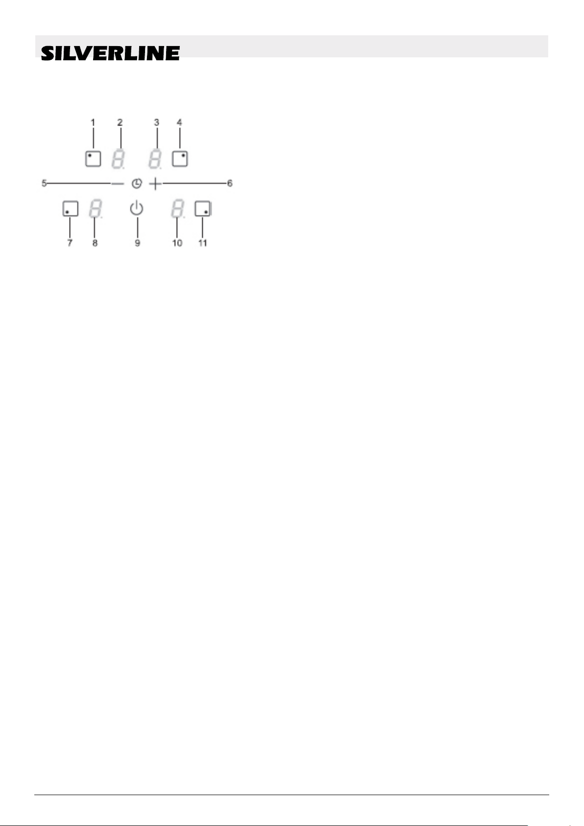
Fig. 1
Control panel
1 Selection button
2 Timer and power indicator
3 Timer and power indicator
4 Selection button
5 [-]Timer button
6 [+]Timer button
7 Selection button
8 Power Meters
9 On / Off button
10 Cooking zone light
11 Selection button
Flow In Premium02/07/2018 11
Page 12

OPERATION OF THE COOKING FIELD
Ventilation
4 OPERATION OF THE COOKING FIELD
Display
Display Designation Function
0 Zero The cooking area is activated
1.....9 Performance levels Power adjustment
U Pot detection Pot is not put on or
E Error display Electronic error
H Residual heat Cooking area is hot
P Booster The booster power is
L Locking The recess is secured.
∏ Bridge 2 Cooking zones are bridged.
unsuitable
activated.
4.1 Ventilation
The fan works automatically. It starts at low speed as soon
as the values released by the electronics exceed a certain
threshold. The higher speed is set when the induction hob is
used intensively.
The fan reduces its speed and shuts off automatically as
soon as the electronics have cooled down sufciently.
Flow In Premium 02/07/201812
Page 13

COMMISSIONING THE COOKING FIELD
5 COMMISSIONING THE COOKING FIELD
5.1 Before the rst heating
First clean your device with a damp cloth, then dry it. Do not use
any detergent that could cause a bluish tint on the glazed surface.
5.2 Induction principle
Below each cooking zone is an induction coil. When the cooking
zone is turned on, this coil generates a magnetic eld. The magnetic eld induces eddy currents in the bottom of the pot, which must
be magnetic. This heats the bottom of the pot. The cooking zone
heats up only indirectly by the heat given off by the pot. The induction cooking zones only work with magnetic cookware:
• Suitable magnetic bottom induction cookware such as
e.g. Cast iron, steel, enameled steel, stainless steel with
magnetic base.
• Unsuitable induction cookware: Copper, aluminum,
glass, wood, earthenware, ceramics, non-magnetic stain-
less steel. The induction cooking zone is automatically
adjusted to the size of the cookware. The cookware must
not fall below a certain bottom diameter, otherwise the
induction does not switch on. Each pot bottom diameter
must have a minimum size, depending on the size of the
cooking zone. If induction cookware is not suitable, the
display will show [ U ].
Switch hob on and off
5.3 Function of the sensor switch panel
The stove is controlled via the sensor buttons. These react to slight
contact of the glass with the nger. If you touch the buttons for
about one second, the control commands will be executed. Each
reaction of the panels is acknowledged with an acoustic and / or
visual signal.
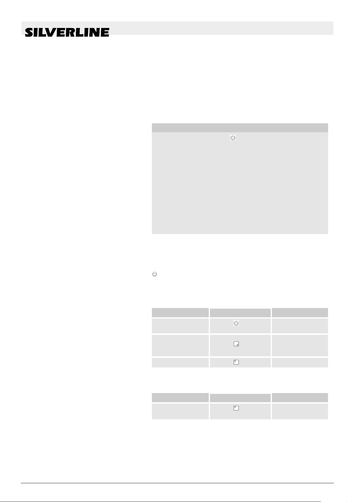
5.4 Switch hob turn on/ turn off
Hob : turn on/ turn off :
Activity Control panel Display
Turn on
Turn off
Cooking zone : turn on/ turn off :
Press [ ]
Press [ ]
4 x [ 0 ]
none or [ H ]
Flow In Premium02/07/2018 13
Page 14

COMMISSIONING THE COOKING FIELD
Residual heat warning indicator
Activity Control panel Display
Choices of the
cooking zone
Increase performance
Reduce power Press [-] [ 9 ] to [ 1 ]
Turn off
If no further input is made, the hob will switch off after approx.
20 seconds for safety reasons and the zeroes will go out.
5.5 Pot detection
Press [ ]
Press [+] [ 1 ] to [ 9 ]
Press [
or press [-]
] and [-] together
4 x [ 0 ]
[ 0 ] or [ H ]
The pot detection ensures perfect safety. The induction does
not work:
• If there is no cookware on the cooking zone or if a pot not suit-
able for induction is used. In diesem Fall kann die Leistungsstufe
nicht erhöht werden und das [ U ] Symbol erscheint in der Anzeige. The [U] disappears when a pot is put back on the cooking
zone.
• If the pot is removed from the cooking zone during cooking, the
cooking zone switches off immediately and the display shows
[U]. The [U] disappears when a pot is put back on the cooking
zone. The cooking zone continues with the previously set power
level.
After use, switch off the cooking zone so that the pan detection
[U] no longer appears.
5.6 Residual heat warning indicator
After switching off the cooking zones or the hob, the residual
heat of the still hot cooking zones is indicated by a [H]. The
[H] goes out when the cooking zones can be touched without
danger. As long as the residual heat indicator is lit, the cooking
zones should not be touched and no heat-sensitive objects
should be placed on it:
Burn hazard!
Flow In Premium 02/07/201814
Page 15

5.7 Power function
COMMISSIONING THE COOKING FIELD
Two cooking zones are equipped with a power function, i.e.
with a power boost. When switched on, these cooking zones
work at extra power for a period of 5 minutes at power level
[P]. The power function is designed to allow you, for example,
to heat large quantities of water quickly, such as boiling pasta
water.
Power: switch on / off:
Activity Control panel Display
Choices of the
cooking zone
Increase
performance
Turn on power Press [+] [P] for 5 min
Press [ ]
Press [+] [ 1 ] to [ 9 ]
4 x [ 0 ]
Timer
5.8 Timer
Turn off power Press [+] [ 9 ]
Automatic control of the power:
The hob is equipped with a high performance. In order not to
exceed this maximum power, the electronics automatically
reduce the cooking level of another cooking zone when the
power function is activated. This cooking zone will then ash
[9] and show the reduced power [7].
Selected cooking zone Other cooking zone (e.g.
Performance level 9)
[ P ] shines [9] is reduced to [7]
With the integrated timer, a cooking time of 1 to 99 minutes
can be set on all four cooking zones. Each cooking zone may
have a different setting.
Switching on or changing the duration:
Activity Control panel Display
Select the cooking
zone
Select power On [ + ] [ 1 ] … [ 9 ] [ P ]
Select timer Press [-] and [+] Timer [00] min
Flow In Premium02/07/2018 15
Press [ ]
[ 0 ]
Page 16

COMMISSIONING THE COOKING FIELD
Timer
Activity Control panel Display
Shorten the time Press [+] from [30] to
29,28,27 ...
Extend time Press [+] The time is ex-
tended
After a few seconds, the ashing stops.
Fourth and the time starts
The duration is
active
Switch off timer:
Activity Control panel Display
Select the
cooking zone
Press [
]
[ 0 ]
Select timer Press [-] and [+] Remaining time
Switch off the
On [ - ] [00] then «off»
timer
If several timers are in operation, you only need to repeat this
operation several times.
Automatic switch off:
When the programmed cooking time has elapsed, [00] will
ash and an acoustic signal will sound. To turn off the beep
and the ashing, just press any key.
Timer as egg timer:
Activity Control panel Display
Switch on the hob
Press ]drücken
Cooking zone
light
Select timer Press [-] and [+] [00] Minutes
Shorten the time Press [+] from [30] to
29,28,27 ...
Extend time Press [+] The time is ex-
tended
After a few seconds, the ashing of the timer lamp stops and the
cooking zone lights go out. When the programmed cooking time
has elapsed, [00] will ash and an audible signal will sound.
To turn off the beep and the ashing, just press any key.
Flow In Premium 02/07/201816
Page 17
5.9 Bridge function
COMMISSIONING THE COOKING FIELD
Locking of the hob
This function allows a bridging of the left cooking zones with the
same functionalities as a cooking zone. Booster function is not
allowed.
Activity Control panel Display
Switch on the hob
Turn bridge on On the 2 left cooking
Press
zones
Press key simultane-
ously
Cooking zone
light
[0] on the front
Cooking zones
and
[Π] on the rear
cooking zones.
5.10 Locking of the hob
Increase performance
Turn off bridge On the 2 left cooking
To avoid a change in the cooking zone setting,
e.g. when cleaning the glass, the operation buttons (except the [
] button) can be locked.
Activate locking:
Activity Control panel Display
Turn on the
trough
Lock the trough Press together
Switch off locking:
Press [+] [ 1 ] to [ 9 ]
zones
Press key simultane-
ously
Press [
[-] and [
front right
Press [
]
] at the
]
[0] or [H] on the 2
Cooking zones
4 x [0] or [H]
No change
4 x [ L ]
Activity Control panel Display
Turn on the
trough
In the 5 seconds after switching on the trough
Flow In Premium02/07/2018 17
Press [
]
[L] on all
display
Page 18

COMMISSIONING THE COOKING FIELD
Locking of the hob
Activity Control panel Display
Locking Together on [-] 4 x [0] or [H]
switch off
and [ ] in front
no indication
press right
Press [-]
Flow In Premium 02/07/201818
Page 19
6 COOKING RECOMMENDATIONS
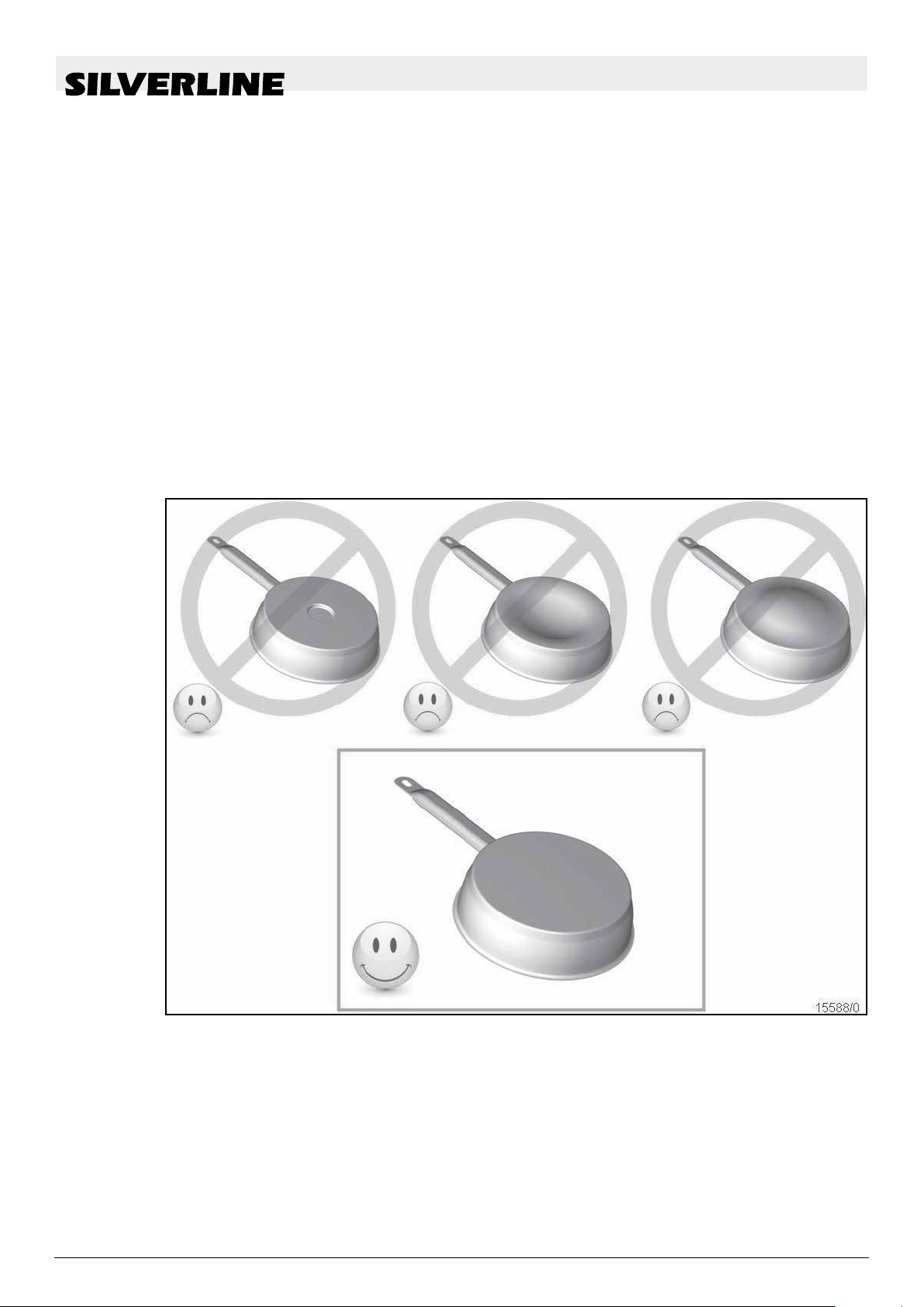
6.1 Cookware
Suitable materials: Steel, enamelled steel, cast iron, magnetic
steel stainless steel, aluminium with magnetic bottom. Unsuitable
materials: Aluminum and stainless steel without magnetic bottom,
copper, brass, glass, stoneware, porcelain The pot manufacturers
specify whether their products are induction-suitable. To check the
induction compatibility of the pots:
Fill the dishes with some water and place it on the induc-
tion cooking zone. Switch the cooking zone to power level
[9]. This water must be warm in a few seconds.
Hold a magnet to the bottom of the dish. If the magnet sticks,
the dishes are suitable.
Some pots may generate noise when placed on an induction
cooking zone. This noise in no case implies a fault of the device
and does not affect its functioning.
COOK RECOMMENDATIONS
Cookware
Flow In Premium02/07/2018 19
Page 20

COOK RECOMMENDATIONS
Setting ranges
6.2 Crockery size
6.3 Setting ranges
The cooking zones automatically adjust to the bottom of the pan
to a certain limit. The cookware must not fall below a certain
bottom diameter, otherwise the induction does not switch on.
Always center the pot in the center of the cooking zone for best
efciency.
(this informations are reference values)
1 to 2 Melting, dissolving, prepara-
tion
2 to 3 Sources, thawing, keeping
warm
3 to 4 Steaming, stewing Fish, vegetables,
4 to 5 Stewing, swelling, thawing Fish, vegetables,
6 to 7 Parboiling, simmering Meat, liver, eggs,
7 to 8 Gentle roast Fish, schnitzel,
9 Baking, cooking Steaks, omelette
P Cook Large quanti-
Sauces, butter,
chocolate gelatin
yoghurt,
Rice, Frozen
meal, sh,
vegetables
fruits
pasta, cereals,
legumes, frozen
foods
sausage goulash,
roulades
bratwurst, fried
eggs
pancakes, lentils
ties of water
Flow In Premium 02/07/201820
Page 21

7 CLEANING AND CARE
Let the device cool down, there could be a risk of burns.
Always clean the dirty hob regularly. Use a damp cloth and
To clean the device, it must be switched off.
Cleaning the device with a steam cleaner or
Never use abrasive or aggressive cleaning agents such as
Then rub the hob with a clean cloth.
Remove sugar, plastic or aluminium foil immediately
CLEANING AND CARE
a little detergent.
cleaner is not permitted for safety reasons
detergents. Grill and oven sprays, stain
ing sand or sponges with scratching
after switching off the cooking zones.
surfaces
high-pressure
.
or rust remover, scour-
Flow In Premium02/07/2018 21
Page 22

ENVIRONMENTAL PROTECTION
8 ENVIRONMENTAL PROTECTION
The packaging materials are environmentally friendly and
recyclable.
Electrical and electronic devices still contain valuable mate-
rials. But you also get harmful substances that are neces-
sary for their function and safety
Therefore never put your old appliance in the residual
waste.
Instead, use the collection center sat up by your municipal-
ity for returning and recycling old electrical and electronic
equipment.
Flow In Premium 02/07/201822
Page 23

9 WHAT TO DO IF…
WHAT TO DO IF…
[E4] appears in the display:
The hob must be recongured. Please follow the instructions
below:
I) Remove all pots from your hob
II) The hob must rst be disconnected from the power sup-
ply: remove the connection cable or switch off the fuse on
the control panel.
III) Turn the power back on.
IV) Process
Disconnect the connection cable or switch off the fuse on the
control panel. Take a pot with magnetic base (diameter > 16
cm). Start programming at the latest 2 minutes after switching on
again Do not press [
V) to delete the existing conguration
1) Press and hold the [-] button
2) With your other nger, press the [O] key (a -> b -> c -> d) one
after the other, counterclockwise. A double "beep" means that
an error has occurred. In this case, start from point 1 again.
3)
Release the button. Then press the [-] and [+] buttons
simultaneously until ashing [E] icons appear.
]
4) Expect the [E] to stay xed
5) [E] will automatically become [C] symbols. The deletion
process is done.
VI) Reconguration of the hob
1) Take a pot with magnetic bottom (diameter
> 16 cm)
2) Select a cooking zone operation when pressing the [O]. 3)
Place the pot on the appropriate cooking zone. 4) Wait until [C]
changes to [-]. The cooking zone is congured.
5) Repeat this process for each cooking zone.
6) The cooking zones are congured as soon as nothing is
displayed. Use the same pot to perform the entire conguration. During conguration, no additional pots should rest on
the trough. If the [E4] indicator remains, contact your service
representative.
Do not switch on the hob or the cooking zones:
The trough is incorrectly connected to the mains.
The backup of the house installation is not inserted correctly.
The hob is locked.
The sensor keys are covered with water or dirt.
A cookware covers the buttons.
The display shows [U]:
Flow In Premium02/07/2018 23
Page 24

WHAT TO DO IF…
The cookware is not on the cooking zone.
The cookware is not induction-suitable
The pot bottom diameter is too small for this cooking zone.
A cooking zone or the entire trough switches off:
The safety shutdown has triggered it.
This is activated if you forget to switch off a cooking zone.
This shutdown is activated when several keys are covered.
A pot is empty and overheated.
Due to overheating, the electronics have automatically re-
duced or even switched off the power automatically
The cooling fan continues after switching off:
This is not a fault, the fan runs until the unit has cooled down.
The fan switches off automatically.
The cooling fan continues after switching off:
This is not a fault, the fan runs until the unit has cooled down.
The fan switches off automatically.
The automatic warm-up does not switch on:
The cooking zone is still hot [H]
The highest power level is switched on [9]
The order display [L]:
See the chapter Locking the hob.
The order display [U]:
See the chapter on keeping warm.
The order advertisement [II]:
See the chapter Pause function.
Display [Π]:
• See the chapter Bridge function in the chapter.
The display will show [ ] or [Er03]:
An object or a liquid covers the keys. The display
as soon as the keys are released or
The display will show [E2] or [E H]:
The hob is overheated, let it cool down rst, and then turn it
back on
The display shows [E3]:
The pot does not t, change the pot.
cleaned.
disappears
The display shows [E6]:
Faulty electrical network. Check the frequency and voltage of
the electrical network.
Flow In Premium 02/07/201824
Page 25

WHAT TO DO IF…
The display will show [E8]:
The air inlet of the fan is clogged, free it.
The display will show [E C]:
• Error in the conguration. Initialize the hob again, see chap-
ter "The [E 4] appears."
If any of the above signs persist, call for service.
Flow In Premium02/07/2018 25
Page 26

INSTALLATION INSTRUCTIONS
10 INSTALLATION INSTRUCTIONS
Assembly and connection may only be carried out by an authorized specialist. The user must ensure that the standards in force
at his place of residence are observed.
After removing the protective foil (3), stick the seal (2) with a
distance of 2 mm from the outside of the glass.
Installation:
Type Mounting dimensions
PHT874S 750 x 490 mm
The distance from the cutout to a wall and / or a piece
of furniture must be at least 50 mm.
This appliance is of type Y for protection against re hazards.
Only appliances of this type may be installed on one side
tall cabinets or walls,
The worktop should be nished with heat-resistant adhesive
(100°C).
The wall end strips must be heat resistant
The hob must not be installed above stoves without fans,
dishwashers, washing or drying equipment.
In order to achieve sufcient ventilation of the electronics in the
hob, an air space of 20 mm is necessary under the trough.
If there is a drawer under the hob, do not store ammable objects,
e.g. spray cans in the drawer.
It must be ensured that the connection cable of the hob is
not exposed to mechanical stress, e.g. through drawers,
after installation.
The cut surfaces should be sealed with special varnish,
silicone rubber or cast resin to prevent swelling due to mois-
ture. Be sure to stick the supplied sealing tape carefully.
ATTENTION:use only protective grids offered by the man-
ufacturer or approved by him for use with the hob.
but the other side must be unobstructed.
of
Flow In Premium 02/07/201826
Page 27

11 ELECTRICAL CONNECTION
To connect the device to the electrical network, hire an
electrician who knows the local regulations
trical supply companies
The contact protection of operationally isolated parts must be
ensured after installation.
You will nd on the nameplate whether the required connec-
tion data correspond to those of the network
The device must be able to be disconnected by isolators
poles of the mains. When switched off, there must be a
tact gap of 3 mm. LS-switches, fuses, RCD's and contactors are considered as suitable separation devices
The installation must be protected by fuses. Electrical cables
must be perfectly covered by installation.
If the device is not equipped with an accessible plug, other
separation options must be considered for xed installation
in accordance with the installation instructions.
The supply cable must be installed so that the hot parts of the
hob are not touched.
Attention !
This device is only designed for a power supply of 230 V ~ 50/60
Hz. Always connect the earth together. Note the connection
diagram. The connection box is located on the underside of the
device. To open the case, use a screwdriver and slide it into the
slots provided.
ELECTRICAL CONNECTION
of the local elec-
and carefully observes them.
all
con-
Network Connection Diameter Electric
wire
230V~
50/60Hz
400V~
50/60Hz
(*) according to EN 60 335-2-6 standard
Connection of the hob:
For the various connection options, use the brass bridge terminals
located in the housing.
Monophases 230V ~ 1P + N
1 Phase
+ N
2 Phasen
+ N
3 x 2.5
mm²
4 x 1.5
mm²
H 05
VV - F
H 05
RR - F
H 05
VV - F
H 05
RR - F
Fuse
25 A *
16 A *
Flow In Premium02/07/2018 27
Page 28

POWER CONNECTION
Bring a pole bridge between terminals 1 and 2. Attach the ground
to the earth terminal, neutral to terminal 4, phase L to terminal 1
or 2.
Biphases 400V ~ 2P + N
Attach the ground to the earth terminal, neutral to terminal 4,
phase L1 to terminal 1, and phase L2 to terminal 2.
Attention ! Unscrew the screws from the housing more than
necessary. Then insert the wires correctly and tighten the
screws
Flow In Premium 02/07/201828
Page 29

12 Device description
12.1 The device
Device description
Operating unit
Fig. 2: Description of the range hood
1 Cooking eld suction
2 Induction cooking eld
3 Engine box
4 Circulation fan box (special accessories)
12.2 Controlunit
Fig. 3:Touch control LED Electronics
1 Unlocking
2 Reduce fan level
3 LED display
4 Increase fan level
5 Delayed automatic shutoff
Flow In Premium02/07/2018 29
Page 30

Device description
Purchased parts package
12.3 Purchased parts package
Control electronics housing
1 Elektronics box
Extractor hood body
1 Glass cover
2 Stainless steel cover
3 Exhaust air tting
4 Cooking eld suction
Engine box
1 Glass cover
2 Stainless steel cover
3 Exhaust air tting
4 Cooking eld suction
Flow In Premium 02/07/201830
Page 31

Device description
Purchased parts package
Fig. 4: Purchased parts package
1 Cooking eld suction
2 Exhaust air tting
3 Elektronics box
4 Engine
5 Screws
6 Screws
7 Screws
8 Operating Guide
Flow In Premium02/07/2018 31
Page 32

For your safety
Symbols in these instructions
13 For your safety
13.1 Symbols in this manual
Safety instructions
Safety instructions are labelled with symbols in this manual. The safety instructions are introduced by signal words that express the extent
of the hazard.
DANGER!
This combination of symbol and signal word indicates an immediately dangerous situation which
will lead to death or serious injuries if not avoided.
WARNING!
This combination of symbol and signal word indicates a possibly dangerous situation which may
lead to death or serious injuries if not avoided.
ATTENTION
This combination of symbol and signal word indicates a possibly dangerous situation which may
lead to minor or light injuries if not avoided.
PLEASE NOTE!
This combination of symbol and signal word
indicates a possibly dangerous situation which
may lead to material damage
if not avoided.
Tips and recommendations
Special safety instructions
This symbol highlights useful tips and recommen-
dations as well as information for efcient and
trouble-free operation.
To draw attention to special dangers, the following symbols are used
in safety instructions:
Flow In Premium 02/07/201832
Page 33

Safety instructions
within handling instructions
For your safety
Symbols in these instructions
Warning signs Type of danger or hazard
Warning of dangerous electrical voltage.
Warning of ammable substances.
Warning of a danger zone
Safety instructions may in particular refer to certain handling instructions. Such safety instructions are embedded in the handling instructions, so that they do not interrupt the reading uency while performing the action. The above-described signal words will be used.
Further labelling
Beispiel:
Loosen the screw.
ATTENTION
Risk of jamming on the lid!
Close the lid carefully.
Tighten the screw.
The following signs and highlighting are used for identifying handling
instructions, result descriptions, bullet lists, references, and other
elements in these operating instructions:
Labelling Explanation
Step-by-step handling instructions
ð
Results of handling instructions
Reference to sections of this manual
and other relevant documents
Bullet lists without a determined order
Flow In Premium02/07/2018 33
Page 34

For your safety
Fire hazard!
13.2 Intended use
The extractor hood is intended for suctioning of any vapour and
steam caused by cooking or frying or preparing otherwise food on
an electric or gas range in private households. The device is not
intended for any commercial usage or any outdoor usage.
Any differing usage is deemed deviating from the intended purpose
and therefore prohibited. We accept no liability for any damages
incurred by any usage that deviates from the intended purpose.
Specically, the following shall be prohibited:
The use outdoors or in the industrial area
The autonomous remodeling or repair of the device n The oper-
ation without metal grease lter
Flambéing
Exhaust air fan operation without window ip switch while simul-
taneously using any replace, furnace, or oven operated with
ambient air
Usage for room air conditioning / ventilation, such as in continu-
ous operation, instead of a fan or adequate ventilation
13.3 Children and persons with limited perception
This appliance can be used by children aged from 8 years and
above and persons with reduced physical, sensory, or mental
capabilities or lack of experience and knowledge if they have
been given supervision or instruction by a person responsible
for their safety concerning the use of the appliance in a safe way
and understand the hazards involved.
Children should not play with the appliance.
Do not allow children to play the with packaging materials. Dan-
ger of suffocation.
Cleaning and user maintenance may not be performed by chil-
dren, unless they are older than 8 years and supervised by a
person responsible for their safety.
Keep the appliance and the power cable out of reach of children
that are 8 years or younger.
Keep children away from the device’s lamps until these have
cooled down. Danger of burning and serious injuries.
13.4 Fire/Fire hazard
Do not ambé any food beneath the device.
Deep frying of any food requires your constant monitoring.
Clean the device surface regularly, to remove any fat residues.
Flow In Premium 02/07/201834
Page 35

For your safety
Clean the metal grease lter at least every other week to pre-
vent the built-up of fat residues on the metal grease lter. These
residues may catch re or ignites spontaneously. Replace the
metal grease lter regularly and/or if needed.
To avoid generating excessive heat, do never operate any cook-
ing zone without a pot or pan or other cookware on it.
Never use open re near the devise.
Never leave hot oil or fat unattended. Do never use water when
trying to extinguish any re caused by oil or fat.
13.5 Room-air-dependent replace (only with exhaust air operation)
If the device is operated in the exhaust air mode and the room
air-dependent replaces are used (eg gas, oil, wood or coal red
heaters, instantaneous water heaters, domestic water heaters or
stoves with replaces), the appliance will deprive the kitchen and
adjacent rooms of room air (Fig. 5). This may cause toxic combus-
tion gases from the chimney or the exhaust air shaft to ow back
into the living areas inside the apartment. Danger of suffocation.
Power Supply
Fig. 5: Fireplace, furnace, or oven
operated with ambient air
Fig. 6: Using a window ip switch
13.6 Power supply
Therefore, you must in particular make sure of:
Use a window toggle switch to allow fresh air to ow in(-
Fig.6).
A fresh air/ exhaust air wall sleeve does not provide sufcient
air supply. Please consult your competent chimney sweeper
who will evaluate the air supply and consumption in your
apartment.
The underpressure inside the room where the replace, fur-
nace, or oven is located must not be less than 4 Pa.
When using the device in the circulation fan operation modus, you
do not need pay any particular attention to the air supply and consumption in your apartment.
The device is powered by electricity; therefore, the danger of an
electric shock persists. Pay particular attention to the following:
If an additional socket is required to connect the device, you
need to engage a professional electrician to perform the re-
spective installation.
You will never touch the plug with wet hands.
You will pay special attention to prevent the bending or jam-
ming of the power cable.
Flow In Premium02/07/2018 35
Page 36

For your safety
Cleaning
13.7 Transport
13.8 Defect
You will pull the mains plug out of the socket in order to discon-
nect the device.
You will only operate the device, if the voltage value stated
on the nameplate coincides with the voltage available at your
socket. The inappropriate voltage may severely damage the
appliance. If you have any questions, please consult a profes-
sional electrician.
While transporting the device in your car, make sure that is
properly secured to protect all passengers from harm or injury.
Use the original packaging, when transporting the device.
Store the packaging for this purpose.
If the device is faulty or damaged, do not attempt to repair it yourself.
Any faulty or damaged power cable or plug must be replaced
to prevent any risk of electric shock. Call the customer service
department ( Ä „CustomerService Hotline (for Germany, Aus-
tria, Switzerland, France, Belgium, Netherlands and Luxem-
bourg)” on page 3).
In order to prevent the danger of electric shock, do never turn
a faulty or damaged device on. Ziehen Sie den Netzstecker
oder schalten Sie die Sicherung im Sicherungskasten aus. Call
the customer service department ( Ä „CustoService Hotline
(for Germany, Austria, Switzerland, France, Belgium, Nether-
lands and Luxembourg)” on page 3).
Always replace defect lamps to prevent overloading the re-
maining lamps.
13.9 Cleaning
Do not you any aggressive or abrasive cleaning agents, since
those may damage the device surface.
Do not you any sharp or pointed object, since those may
scratch the device surface.
Do not use a high pressure or steam cleaner, since the pene-
trating humidity may cause an electric shock.
Observe the cleaning intervals for metal grease lters indicated
in this operating manual. Otherwise, the risk of re hazard will
occur.
Flow In Premium 02/07/201836
Page 37

14 Operation
14.1 Ensuring safe control and operation
WARNING!
Risk of injury due to improper operation!
Improper operation will cause the danger of
serious injuries and property damage.
– Check the device before every use. A faulty or
damaged device must not be used.
– Do not place any objects on the device, since
they may fall down.
– Do never operate the device without the
metal grease lter. Risk of re hazard.
– Switch the device always on, to prevent corro-
sion damages caused by condensation.
Operation
Turning on/off the fan > concerning the control unit
14.2 Switch fan on / off
14.2.1 About the control unit
Switching on the fan
Fig. 7: Fan On/Off
You may turn the fan on/off using the control unit or the remote
control.
Turn the fan on when you start cooking and wait
10-15 after you nished, before turning off the
device.
This will ensure the best possible removal of cooking
vapours.
1.
2.
When the device is not in operation, the digital display is
in standby mode and appears as a dot. As soon as any button is
pressed, a ashing “L” (i.e. lock) appears 3x on the digital display.
After that, press and hold down the timer button until
“0'” appears on the digital display (Fig. 7/1).
The fan has been unlocked
3. After unlocking the fan, you can use the + and - but-
tons to set the speed of the fan (Fig.7 / 2,4).
Now setting up the fan operation speed is completed.
Flow In Premium02/07/2018 37
Page 38

Operation
Turning the delayed shut-off automatic on/off
14.3 Change the power level of the fan
You may change the fan power level and set up the desired
level by using the control unit or the remote control.
14.3.1 About the control unit
Fig. 8: Multi-level switch for the fan
2. Increase the fan speed by pressing the
button ‚+‘ (Fig.8/4).
Fan level has been increased.
ð
3. Reduce the fan speed by pressing the
button
‚-‘(Fig.8/2).
Fan level has been reduced.
If for 10 minutes, no button has been pressed, the
device will switch into the standby mode and get
locked.
To turn off the fan, press the button until “0” appears on the digital display.
14.4 Turning the delayed shut-off automatic on/off
If while the device is running on any level, the button is pressed,
the 15 minutes timer will be activated. As soon as the timer starts
counting down, the speed value on the digital display will start
ashing. After 15 minutes, all functions that were activated prior to
the timer, will shut down.
Turning the delayed shut-off automatic on
1.
Press the Timer button Fig. 9/5).
Delayed shut-off automatic has been activated.The engine
will automatically shut down after 15
When the delayed shut-off automatic
has been activated, the speed value on
the digital display will start ashing.
minutes.
Fig. 9: Turning the delayed shut-off automatic on/off
Turning the delayed shut-off automatic off
2. Press the sensor button again (Fig.9/5).
Delayed shut-off automatic has been deactivated.
Flow In Premium 02/07/201838
Page 39

14.5 To clear the fat lter saturation indicator
When the digital screen is displayed, the metal grease lter must be cleaned(Fig.10). To delete the metal grease lter
cleaning prompt, proceed as follows:
To delete the fat lter saturation indicator (Fig. 10/2)
press and hold the '-' key while the trigger is off but in the
ejected state until 'E' appears on the screen.
Now the metal grease lter cleaning prompt has been
deleted.
Fig. 10: Deleting the metal grease lter cleaning prompt warning
Operation
To clear the fat lter saturation indicator
Flow In Premium02/07/2018 39
Page 40

Maintenance, cleaning, and care
Maintenance > maintenance intervals
15 Care, Cleaning and maintenance
15.1 Care
Electrical voltage
DANGER!
Danger to life due to high voltage!
There is an immediate risk of fatal injury in
case of contact with live parts of the device.
– Pull out the mains plug from the socket or
switch off the fuse inside the fuse box, before initiating any maintenance or cleaning
work.
Maintenance intervals
PLEASE NOTE!
The device performance will be negatively im-
pacted by any non-compliance with the maintenance intervals!
In case of overlong use, the metal grease lter as
well as the activated carbon lter will be clogged
with fat and dirt particles, which will negatively
impact the device performance.
– Please observe all maintenance intervals
specied in this manual.
15.1.1 Maintenance intervals
Interval Maintenance task
after assembling and in case of heavy contamination
after cleaning the extractor hood Servicing the device.
every other week or when the grease lter prompt
appears
Outside cleaning of the device.
Cleaning the metal grease lter.
every 3 month or in case of decreasing performance
Cleaning or replacing the activated carbon lter (for circulation fan operation only).
Flow In Premium 02/07/201840
Page 41

15.1.2 Device dimensions
Remove the metal grease lter
Maintenance, cleaning, and care
Maintenance > Cleaning the metal grease lter
WARNING!
Fire hazard due to grease and fat residues
inside the metal grease lter!
There is a risk of re due to fatty deposits in
the metal grease lter!
– Clean the metal grease lter as soon as the
instruction for cleaning the lter appears or at
least every 2 weeks.
– Never operate the extractor without the metal
grease lter.
The metal grease lter retains solid components from vapors in
the kitchen (such as oil or dust) and greatly reduces fume hood
contamination.
Fig. 11: Removing the metal cover
1 Cover
2 Extractor hood box
Fig. 12: Removal of metal grease lters
1 Cleaning the metal grease lter
1.
Remove the metal cover on the air inlet duct of
your hood box (Fig.11).
2. Remove the metal grease lter by moving it in the direction
of the arrow. Make sure the metal grease lter does not fall
off.
3.
it
(Fig. 12).
4. Rinse the metal lter by hand or in the dish-
Lay the metal grease lter forward and remove
washer.
Flow In Premium02/07/2018 41
Page 42

Maintenance, cleaning, and care
Maintenance > Cleaning the metal grease lter
Manual Cleaning
5.
PLEASE NOTE!
Damage due to incorrect cleaning or due to the
use of unsuitable cleaning agents!
Cleaning in the dishwasher
After cleaning
Inserting the metal grease lter
Let the metal grease lter soak in warm soap water and clean it using
a soft brush.
6. 6. Rinse with water the metal grease lter with warm water.
7.
8.
9.
10.
11. Clearing the warning for cleaning the metal
12. Close the metal grease lter lid of the extractor
Place the metal grease lter loosely and
vertically without adding other tableware into the
dishwasher.
Start any program with a temperature of no higher than
55°C.
Due to the cleaning in the dishwasher, the
lter parts may experience slight changes in
their colour.
This does not affect function or perfor-
mance to the metal grease lter.
Put the metal grease lter on a on an absor-
bent pad
Move the metal grease lter in the direction
of the arrow and insert it into the air extraction
ductFig.13).
grease lter
hood
(Fig.13).
Fig. 13: Inserting the metal grease lter
Flow In Premium 02/07/201842
Page 43

Maintenance, cleaning, and care
Maintenance> Clean or replace activated carbon lter (only recirculation mode)
Cleaning the drip tray
13.
Fig. 14
1 Extractor hood box
2 Equipment slot
To keep water and food waste, the hat box has a slot inside
(Fig. 14/2).
How to clean the inner box;
Pull up inside the device slot (Fig. 14).
The hood box can be cleaned in the dishwasher.
After cleaning, insert the inner box again.
15.1.3 Clean or replace activated carbon lter (recirculation only)
1. Take out the activated carbon lter (Fig. 15/2) in
the direction of the arrow towards the front.
magnets) ( Fig. 15).
(is held with
Fig. 15
1 Activated carbon lter housing
2 Activated carbon lter with frame
Fig. 16
2.
Unscrew the connecting screw (Fig. 16/1) (Fig.16).
ATTENTION!
Place the case on a rm surface, then push
the lter down slightly to remove it.
Flow In Premium02/07/2018 43
Page 44

Maintenance, cleaning, and care
Cleaning and maintenance > Cleaning agents/devices
1 Connecting screw
2 Activated carbon lter
Fig. 17
Inserting the activated carbon lter
3.
4.
5.
Remove the activated carbon lter from the lter
frame as shown on (Fig. 17)
Allow the activated carbon lter to regenerate for one
hour inside the baking oven at about 200°C. After cooling
down, re-insert the lter into the hood.
This procedure may be repeated not more than 10 times,
after that lter must be replaced by a new one.
Re-insert the activated carbon lter by performing the
previous steps in reverse order.
.
15.2 Cleaningand care
15. 2 .1 Cleaningsupplies/utensils
PLEASE NOTE!
Property damage due to unsuitable cleaning proce-
dures!
Unsuitable cleaning procedures may result in
property damages.
– Always use the cleaning agents/devices
specied in this operating manual only.
– Do not use a high pressure or steam cleaner.
– Never use aggressive and abrasive cleaning
agents or sharp and pointed objects.
– Before you start cleaning, take off any jewel-
lery, to prevent scratching the surfaces.
For the different surface type, please use the in following specied cleaning agents/devices:
Flow In Premium 02/07/201844
Page 45

Maintenance, cleaning, and care
Cleaning and care > Servicing the device
Surface Cleaning agent Cleaning implement
Stainless steel
Glass
lacquered surfaces
Stainless steel detergent soft cloth
Soft sponge
glass cleaning product
warm soap water
warm soap water soft cloth
soft cloth
Soft sponge
15.2.2 Clean the device from the outside
6. Apply the respective cleaning agent (stainless steel or
glass) with a soft cloth.
7.
8. Maintain the device.
Wipe the device thoroughly dry using a soft cloth.
15.2.3 Maintaining the device
To prevent the fast re-soling of the stainless steel parts, the
treatment with a stainless steel care spray is necessary.
9.
10.
Apply with a soft cloth the stainless steel care spray in
a very thin layer on the stainless steel parts of the device.
Lacquered surfaces do not require any additional care
(do never apply any stainless steel care spray on such
surfaces)
Flow In Premium02/07/2018 45
Page 46

Error messages
Error table
16 Error messages
16.1 How to behave in case of errors
The following rule always applies:
Always perform the repair steps specied in this operating
manual only.
Für weitere Reparaturen kontaktieren Sie den Kunden-
dienst
Ä „Customer Service Hotline (for Germany,
Austria,
Luxembourg)”
WARNING!
Danger of injuries due to using a defective
device!
A defective device may cause serious injuries.
– Do never use a defective device.
– Pull out the mains plug from the socket
or switch off the fuse inside the fuse box,
before searching for possible errors.
Switzerland, France, Belgium, Netherlands and
on page 3.
Inappropriately performed repairs will void
the manufacturer's warranty.
16.2 Error table
In all technical devices, errors might occur. These represent not always
necessarily a defect of the device.
Therefore, you should consult the following table and check whether you
can x the error yourself.
Error description Cause Solution/remedy
Device does not function No connection to the
Loss of performance
efciency / increased
operating noise
mains power supply
Defective fuse Check the fuse inside your fuse box.
Power failure Check the function of other electric equipment.
Dirtied metal grease lters Clean the metal grease lters
Dirtied activated carbon lter
pad (for circulation fan only)
Connect the device to the mains power supply.
Clean the activated carbon lter pad or replace it
with a new one.
Exhaust air duct
cross-section too small;
(less than Ø 150 mm)
Flow In Premium 02/07/201846
Ask a professional technician to check the exhaust
air duct cross-section size.
Page 47

Error messages
If you cannot solve the issue using the present
table, call the customer service department
( Ä „Customer Service Hotline (for Germany,
Austria,Switzerland, France, Belgium,Netherlands
and Luxembourg)” on page 3).
Error table
Flow In Premium02/07/2018 47
Page 48

Accessories and spare parts
Accessories > Accessories circulation/exhaust air fan control
17 Accessories and spare parts
17.1 Ordering accessories and spare parts
WARNING!
Danger of injury through the use of unsuitable
accessories or spare parts!
Using unsuitable or faulty accessories or spare
parts may compromise your safety and cause you
damage, malfunctions or complete failure of the
device.
– Only use original SILVERLINE spare parts or
accessories approved by SILVERLINE.
–
In case of any uncertainties, always
call the customer service department
„Customer service -Hotline (forGermany,
Austria,Switzerland, France, Belgium, Netherlands and Luxembourg)”
on page 3.
Ä
For more information, please visit www.
silverline24.de.
Purchase any spare parts or accessories either through your
retail dealer or the service department
Hotline (for
erlands and Luxembourg)” on page.
Germany, Austria,Switzerland, France, Belgium, Neth-
The use of not authorised spare parts and
accessories authorised will void the warranty
granted by the manufacturer.
17.2 Accessories
17.2.1 Accessories circulating air exhaust circuit
Ä „Customer Service
Flow In Premium 02/07/201848
Page 49

17.2.2 Accessories exhaust air fan operation
Window ip switch with cable
Fig. 18 Item no.: FKS cable
Accessories and spare parts
Accessories > accessories exhaust air fan operation
Fig. 18: Window ip switch with
cable
Radio-operated window ip switch
Fig. 19: Radio-operated window ip switch
Fig. 19 Item no.: FFKSL
Flow In Premium02/07/2018 49
Page 50

Accessories and spare parts
Accessories > accessories circulation fan operation
Fig. 20: Exhaust gas temperature
sensor device with ATW CABLE
Fig. 20
Fig. 21 Item no.: ATW RADIO
Item no.: ATW CABLE
Fig. 21: Exhaust gas temperature sensor device with ATW-RADIO
17.2.3 Accessories recirculating air operation
Activated carbon lter
Fig. 22 U-START 811, Item no.:
Fig. 22: Activated carbon lter
Flow In Premium 02/07/201850
YM974.3413.01
.
Page 51

Activated carbon lter
Accessories and spare parts
Extractor hood accessories
Fig. 23
17.2.4 Cleaning/care products
Stainless steel care spray
Fig. 24: Stainless steel care spray
Fig. 23
Fig. 24
AF 811, Item no.:
YM974.3413.02
PS 500, Item no.: YT950.0000.05
17.3 Extractor hood accessories
High quality metal grease lters
Fig. 25: High quality metal grease lters
Fig. 25
Ask your specialised kitchen equipment
retailer for a metal grease lter tting for you
extractor hood. Alternatively, you may nd
the required information on our website www.
silverline24.de.
Item no.: YT142.3413.01
Flow In Premium02/07/2018 51
Page 52

Disassembly and disposal
Disassembly > dismantling the device
18 Disassembly and disposal
18.1 Dismantling
18.1.1 Safety during disassembly
High self weight
ATTENTION
Risk of injury caused by device falling down!
The heavy device weight may cause the risk of
injuries.
– Always ask a another person to secure the
device, while assembling or disassembling it.
18.1.2 Disassembling the device
1. Move the activated carbon lter (Fig. 26/2) towards
Fig. 26
1 Activated carbon lter housing
2 Activated carbon lter
ATTENTION
Disconnect the device from the mains
power supply.
the direction of the error (Abb.26).
Flow In Premium 02/07/201852
Page 53

Fig. 27
1 Activated carbon lter housing
2 Connecting screw
Disassembly and disposal
Disassembly > Dismantling the device
2. Unscrew the connecting screw(Fig.27/1) and re-
move the activated carbon lter housing (Fig.27).
4. Loosen the screws A, B, C, D, E, F of the air extraction
connection on the motor(Fig. 28).
5.
Disconnect the power connection of the device and
remove the motor.
Fig. 28
Fig. 29
1 Mounting screws of the device
2 Equipment
Fig. 30
1 Assembly screws
2 Hood use
3 Mounting screws
7. Loosen the mounting screws(Fig. 29 /1).
9.
Turn the clamping screws and remove the cap insert
(Fig. 30).
10. Remove the connecting piece on the hood insert (Fig.
30).
Flow In Premium02/07/2018 53
Page 54

Disassembly and disposal
Disposal
18.2 Disposal
Packaging
Fig. 31: Recycling
Extractor hood
Fig. 32: Electrical scrap
The symbol in Fig. 31 refers to the environment-friendly, re-usable
materials of the packaging. Dispose such material in the disposal
container expressively specied for this purpose only.
Device marked with the symbol in Fig. 32 must not be disposed
into the regular household waste, but delivered to the indicated
recycling centres for electric and electronic devices.
ENVIRONMENT!
Danger to the environment resulting from
wrongful disposal!
The wrongful disposal can cause hazards for the
environment.
– The disposal of electrical scrap and electron-
ic components must always be carried out by
properly authorised specialist companies.
– If in doubt, contact your local administration
or a local specialist company for disposal and
recycling for more information.
Activated carbon lter pad (for circulation
fan operation only) The discarded activated carbon lter pads may
be disposed into the household waste.
Activated carbon lter honeycomb lter
(for circulation fan operation only) Discarded honeycomb lter may
be disposed into the household waste.
Flow In Premium 02/07/201854
Page 55

Technical specications
19 Technical specications
Versions FLIK 854 ES
Order numbers FLIK 854 ES
Design type Cooking eld air duct
Operating mode Exhaust air fan or circulation fan operation
Dimensions (W x D) [mm] 780 x 520
Weight [kg] 20 / 25
Power supply connection 220–240 V~/50 Hz
Engine power output [W] 155 W
Overall performance [W] 155 W
Connection exhaust air duct
Exhaust air discharge power Min./Max. Normal operation 386/473 m3/h
Noise impact [dB(A) with power level 2] Min./Max. Normal operation 67/66 dB(A)
Ø
*Pursuant to EU regulation 65/2014 – EN61591, EN60704-2-13,
*Pursuant to EU regulation 65/2014 – EN61591, EN60704-2-13,
150 mm
EN50554.
EN50554.
Cleaning the metal grease lter dishwasher-proof
Number of activated carbon lter (circu-
lation fan operation)
Protection class 1
Subject to technical changes!
1
Flow In Premium02/07/2018 55
Page 56

Type plate
20 Nameplate
The type plate is located behind the metal grease lter
inside the hood body and contains the above listed information:
Fig. 33: Type plate (Example)
1 Model name
2 Item number
3 Manufacturer
4 Revision number
5 Serial number
6 Customer service
7 Technical specications
Flow In Premium 02/07/201856
Page 57

21 Warranty
Warranty
In Germany, Austria, Switzerland, France, Belgium, Netherlands
and Luxembourg
In accordance with the following provisions, we guarantee the end
customer that the device delivered to the end customer will be free
of material or processing defects within a period of 2 years from
delivery (guarantee period).
Warranty claims can only be made within a period of max. 2 years
from date of delivery.
Within this warranty period, we will, at our discretion, repair or replace
the device, free of charge, any defects resulting from material or
manufacturing defects. Other claims of the end customer against us,
in particular for damages, are excluded. The contractual or legal rights
of the customer to the respective seller are not affected by this guarantee.
This guarantee is only valid if
the device does not show any signs of damage or signs of wear
caused by a use which deviates from the normal requirements
and specications of the manufacturer (according to the user
manual),
the value or serviceability of the device is not only negligibly
affected by the defect,
the device is subject to visible external damage before assembly,
the device does not have any features that indicate repairs or
other intervention by workshops
er,
the product has no defects and consequential damage caused
by incorrect or insufciently
by the incorrect or insufciently dimensioned exhaust air duct,
the fabrication number has not been removed or made
illegible,
the device or accessories are freely accessible.
The warranty does not cover wear parts, lters used, easily breakable
parts such. As glass or plastic or incandescent bulbs with the exception that the bulbs initial equipment a guarantee of 8 days is granted.
Any claims arising from this warranty assume that the end customer
has contacted their locally responsible service representative (mentioned in the user manual) and has given them the opportunity to conduct a (telephone) fault analysis within a period of 7 days. Any claims
arising from this warranty may then only be asserted by handing over
or sending the device either to the repair centre by named by the customer service or the manufacturer’s own local service centre, provided
that customer service has declared the complaint as being
not authorized by the manufactur-
dimensioned exhaust air duct,
Flow In Premium02/07/2018 57
Page 58

Warranty
justied. A condition of the warranty claim is still the submission of the
original invoice and the delivery note with delivery date. We assume
the costs of an on-site service. however, if the customer service re-
sponsible for the consignment calls the end customer a specic freight
carrier and the customer uses another freight carrier, we will not be
able to meet the costs of the consignment. The end customer is not
entitled to return the unit at our expense, unless we agree to reimburse
the customer in writing. Otherwise, we reserve the right to charge the
transport costs to the end customer.
If warranty claims are asserted and if, during the testing of the unit by
us or the responsible customer service, it is found that no fault has
occurred or the warranty claim is not met for any of the above reasons,
we are entitled to charge a service fee of EUR 75,00 to raise. This
does not apply if the end customer proves that he was unable to recognize under the circumstances that the warranty claim did not exist.
This warranty applies to the extent and under the above conditions (including submission of proof of purchase and delivery even in the case
of resale) for any subsequent future owner of the equipment.
To assert warranty claims, we also need to provide the following information:
Name, address and telephone of the end customer
Information about the person / company who carried out the
installation
Information on the nameplate inside the device (part number,
model drawing, revision number, serial number)
Day of installation at the end customer
Detailed description of the defect
These warranty conditions apply to devices purchased in Germany,
Austria, Switzerland, France, Belgium, Netherlands and Luxembourg.
For devices used abroad that have the technical prerequisites (eg
voltage, frequency, etc.) for the corresponding country and that are
suitable for the respective climatic and environmental conditions, these
terms of guarantee also apply insofar as we comply with have a customer service network in the respective country.
This guarantee is subject to the law of the Federal Republic of Germany.
Enter your device data here:
Item number
Model name
Revision number
Serial number
Date of purchase / day of
installation
Flow In Premium 02/07/201858
Page 59

For any questions concerning complaints,
please call the customer service department
Ä „Customer service hotline (for Germany, Aus-
tria,Switzerland, France,Belgium, Netherlands and
Luxembourg)”
on page 3).
Warranty
(
Flow In Premium02/07/2018 59
Page 60

Unpacking and assembling
Unpacking
22 Unpacking and assembling
22.1 Unpacking
All parts of the extractor hood are shipped packed together in cardboard
box.
WARNING!
Danger of suffocation if children play with the
packaging material!
Children that play with the packaging material are
in der danger of accidental suffocation.
– Storage the packaging material out of the
reach of children or persons that may no understand theses dangers.
1. Unpack the extractor hood and all further parts in-
cluded in the box and check the content for complete-
ness and whether everything is free from visible errors.
2. Check the engine function.
If you detect any damage, contact immediately your
specialist retailer or the customer service department ( Ä „Customer servicehotline (for Germany,
Austria,Switzerland, France, Belgium, Netherlands
and Luxembourg)” on page 3). In this case, the
device must not be assembled.
Flow In Premium 02/07/201860
Page 61

To be considered before assembling > exhaust air fan operation
22.2 To be considered before assembling
22.1 Exhaust air fan operation
You may run the extractor hood in the exhaust air fan operation mode.
WARNING!
Danger to life for using any replaces, furnac-
es, or ovens operated with ambient air!
The usage of any replaces, furnaces, or ovens
operated with ambient air simultaneously to the
extractor hood may result in danger of suffocation.
– Always ensure the sufcient inow of fresh air,
for example by using a window ip switch.
– If you have any questions, please consult
your competent chimney sweeper.
Fig. 34: Exhaust air fan operation
In extract air mode, the kitchen fumes are drawn in, cleaned via the metal
grease lter and directed outwards through the exhaust air duct (Fig. 34).
Unpacking and assembling
Advantages
The exhaust air must not be vented through a
chimney that is used for venting exhaust fumes
of any devices operated with gas or other combustible fuels.
Always comply with all statutory and administrative
provisions regarding the disposal of exhaust air.
The activated carbon lter is not required.
Unpleasant odours are reduced.
Lower condensation
Flow In Premium02/07/2018 61
Page 62

Unpacking and assembling
To be considered before assembling > circulation fan operation
Disadvantages
Fig. 35: Using a window ip switch
22.2.2 Circulation fan operation
A wall opening (possibly requiring a core hole drilling) with
a diameter of 150 mm is necessary.
If you opt for using the exhaust air operation and
have not any connection facility for the exhaust
air duct yet, contact please a specialist company
and ask them to perform the wall opening.
You may run the extractor hood in the circulation air fan operation mode.
WARNING!
Danger of re hazard due to clogged air slots!
Air slots clogged or obstructed by objects
may cause re hazard.
– Check the air slots for clogging or dirt accumu-
lations and remove them, if needed.
– Do not install any wall cabinets before the air
slots of the extractor hood.
Fig. 36: Circulation air fan operation
Advantages
Disadvantages (in comparison to
exhaust air fan operation)
In recirculation mode, the kitchen fumes are sucked in, cleaned
by the metal grease lter (activated charcoal lter pad not included in delivery) and returned to the room air through the air slots
(Fig. 36).
The activated carbon lter pad can be purchased as
accessory.
Easy Assembly (wall opening required)
Energy-saving operation
Activated carbon lters required lower exhaust performance high-
er noise level
higher odor nuisance
higher condensation
Flow In Premium 02/07/201862
Page 63

22.2.3 Power supply connection
So that no disruptive cable is visible, you should plan the power
connection before mounting.
Unpacking and assembling
Assembling the device > assembly diagram
WARNING!
Danger to life due to improper installation!
Incorrect installation of an additionally required
socket may result in electric shock.
- Contact a qualied electrician if you need an
additional socket.
You must install the cooker hood in such a way
that you can reach the mains plug even after installation.
AFig. 37
Fig. 38
22.3 Assembling the device
22.3.1 Assembling diagram
Complete assembling the stove inside the kitchen counter top.
1.
2. Attach the device to the metal base on the stove (Fig. 38).
Fit the exhaust air adapter for the at duct of the metal
air extractor with the 4 mounting screws
(Fig. 37).
Flow In Premium02/07/2018 63
Page 64

Unpacking and assembling
Assembling the device > assembly diagram
(Fig. 39). Mounting the device on the stove
1 Mounting screws of the product
2 Product
3.
4. Switch box (Fig. 40/2) Use the mounting screws to install
Carry out the installation of the device with the 4
screws (Fig. 39/1).
the switch box in the kitchen worktop (Fig. 40/1).
Fig. 40
1 Assembly screws for the switching circuit
2 Control box
Fig. 41
5.
Drill a hole of Ø260 mm for the engine ex-
haust air duct (Fig.41).
6. Cut-out at the bottom Do not draw the air extract with the screws A, B, C, D, E, F (Fig. 42).
Fig. 42
Flow In Premium 02/07/201864
Page 65

Assembling the device > Reducing adapter (for exhaust air fan operation with Ø 125 mm air duct only)
Fig. 43
1 Activated carbon lter housing
2 Connecting screw
Unpacking and assembling
7. Place the activated charcoal lter housing (Fig.
43/1) in the prepared cutout.
Fixate the activated carbon lter housing (Fig. 43/2) inside
the prepared opening using 2 screws.
Fig. 44
1 Activated carbon lter housing
2 Activated carbon lter
Fig. 45: POWER SUPPLY CONNECTION
8.
Insert the activated carbon lter (Fig. 44/2) into the
activated carbon lter housing (Fig. 44/1)
9. Establish the power supply connection for the device;
10.
tion box designated for cooking ranges (Fig. 45/2) with the
data cable from the switch box (Fig. 45/3).
11.
into the socket (Fig. 45/5) (Fig. 45).
12.
the socket (Fig. 45/5).
13.
(Fig. 45/6) into the plug on the motor (Fig. 45).
14.
Connect the cooking eld power cable with ajunc-
Plug the mains cable of the hob extractor (Fig. 45/1)
Plug the power cord of the control box (Fig. 45/4) into
Plug the motor connection cable from the control box
Complete connecting the device with the air outlet.
22.3.2 Assemble the reducing adapter (for exhaust air fan operation
with Ø 125mm air duct only)
For the exhaust air fan operation, a wall opening (possibly requiring a core hole drilling) with a diameter of 150 mm is necessary.
Flow In Premium02/07/2018 65
Page 66

Unpacking and assembling
Assembling the device > Assembling the cooking eld
22.3.3 Assembling the cooking eld
High self weight
Using the reducing adapter and an air duct with a
diameter of 125 mm decreases the efciency of
exhaust air ventilation and notably increases the
operating noise of the extractor hood.
ATTENTION
Risk of injury caused by device falling down!
The heavy device weight may cause the risk of
injuries.
– Always ask a another person to secure the
device, while assembling or disassembling it.
Flow In Premium 02/07/201866
Page 67

Unpacking and assembling
Assembling the device > installing the window ip switch (for exhaust air fan operation only)
22.3.4 Installing the window ip switch (for exhaust air fan operation only)
Simultaneously using a extractor hood while operating any replace, furnace, or oven operated with ambient air requires the
installation of a window ip switch to ensure a sufcient fresh air
supply.
1.
2. Press the lid (Fig. 46) together along its long sides, to
Fixate the window ip switch at the window.
For more information, please see the
manufacturer’s operating manual.
You will more information and order instructions in the .
open the black box (Fig. 46), and take the lid off (Fig. 46)
.
Fig. 46: Opening and closing the box
Flow In Premium02/07/2018 67
Page 68

Unpacking and assembling
Assembling the device > connecting the exhaust air duct (for exhaust air fan operation only)
3. Loosen the screws and remove the cable bridge
(Fig.47/1).
4.
Insert the window ip switch cable into the stranded wire hole replacing there the cable bridge (Fig.
47
/2) and re-tighten the screws.
5. Put the lid back on the black box.
Fig. 47: Taking out the cable bridge
22.3.5 Establish power supply
WARNING!
Risk of injury from damaged power cable!
Connect the power plug with the selected mains socket outlet, without bending the power cable.
22.3.6 Connecting the exhaust air duct (for exhaust air fan operation only)
Connect the exhaust air ttings with a diameter of 150
mm with the exhaust air duct with the same diameter size.
For best results of reducing the extractor
hood operating noise, use a smooth walled
circular tube with a diameter of 150 mm.
A smaller air duct diameter reduce the
extraction efciency and results in greater
operating noise.
Flow In Premium 02/07/201868
Page 69

22.4 Cleaning the extractor hood
Unpacking and assembling
Cleaning the extractor hood
PLEASE NOTE!
Property damage due to neglected cleaning!
– After assembling the extractor hood, clean its
external surfaces (chapter 15.2.2
cleaning of the device.” on page 45
treat them according to the given instructions
(chapter 15.2.3 „Servicing the device“
page 45).
“Outside
) and
on
Flow In Premium02/07/2018 69
 Loading...