

Page 1

silabs.com | Building a more connected world. 1 | Page
RS9116W BLE AT Command Programming
Reference Manual
Version 2.1
February 10, 2021
Page 2

RS9116W BLE AT Command Programming Reference Manual
Version 2.1
silabs.com | Building a more connected world. 2 | Page
Table of Contents
1 Architecture ............................................................................................................................................................ 5
2 Bootloader .............................................................................................................................................................. 7
3 Host Interfaces ..................................................................................................................................................... 18
3.1 UART Interface ............................................................................................................................................. 18
4 Command Mode Selection ................................................................................................................................... 20
5 Command Format ................................................................................................................................................. 21
6 BLE Commands .................................................................................................................................................... 29
6.1 Generic Commands ...................................................................................................................................... 29
6.1.1 Set Operating Mode...................................................................................................................................... 29
6.1.2 Query RSSI ................................ ................................................................................................ .................. 35
6.1.3 Query Local BD Address .............................................................................................................................. 35
6.1.4 Query BT Stack Version ............................................................................................................................... 35
6.1.5 BLE PER Transmit ....................................................................................................................................... 36
6.1.6 BLE PER Receive ........................................................................................................................................ 37
6.1.7 PER CW Mode ............................................................................................................................................. 39
6.2 BLE Core Commands ................................................................................................................................... 39
6.2.1 Advertise Local Device ................................................................................................................................. 39
6.2.2 Scan ............................................................................................................................................................. 40
6.2.3 Connect ........................................................................................................................................................ 42
6.2.4 Disconnect ................................................................................................................................................... 43
6.2.5 Query Device State....................................................................................................................................... 43
6.2.6 Start Encryption ............................................................................................................................................ 44
6.2.7 SMP Pair Request ................................ ................................................................................................ ........ 44
6.2.8 SMP Response ............................................................................................................................................ 45
6.2.9 SMP Passkey ............................................................................................................................................... 45
6.2.10 Initialize BLE Module .................................................................................................................................... 45
6.2.11 Deinitialize BLE Module ................................................................................................................................ 46
6.2.12 BT Antenna Select ........................................................................................................................................ 46
6.2.13 BLE Set Advertise Data ................................................................................................................................ 46
6.2.14 BLE Set Scan Response Data ...................................................................................................................... 47
6.2.15 BLE Set LE Ping Timeout ............................................................................................................................. 47
6.2.16 BLE Get LE Ping Timeout ............................................................................................................................. 48
6.2.17 BLE Set Random Device Address ................................................................................................................. 48
6.2.18 BLE Data Encrypt ......................................................................................................................................... 49
6.2.19 BLE Whitelist ................................................................................................................................................ 49
6.2.20 BLE Set MTU Size Command ................................ ....................................................................................... 49
6.2.21 BLE Set Phy Command ................................................................................................................................ 50
6.2.22 BLE Read Phy Command ............................................................................................................................. 50
6.2.23 BLE Set Data Length Command ................................................................................................................... 51
6.2.24 BLE Read Maximum Data Length Command ................................ ................................................................ 51
6.2.25 BLE_Resolvlist ............................................................................................................................................. 52
6.2.26 BLE GetResolvlist Size ................................................................................................................................. 52
6.2.27 BLE SetResolution Enable ................................................................ ............................................................ 52
6.2.28 BLE SetPrivacy Mode ................................................................................................................................... 53
6.2.29 BLE Connection Update Command .............................................................................................................. 53
6.3 BLE GATT Profile Commands ...................................................................................................................... 54
6.3.1 Query Profiles List ........................................................................................................................................ 54
6.3.2 Query Profile ................................................................................................................................................ 54
6.3.3 Query Characteristic Services ................................ ....................................................................................... 55
6.3.4 Query Include Services ................................................................ ................................................................. 55
6.3.5 Read Characteristic Value By UUID .............................................................................................................. 56
6.3.6 Query Attribute ............................................................................................................................................. 56
6.3.7 Query Attribute Value ................................................................................................................................... 57
6.3.8 LE L2CAP Credit Based Flow Control Connection Request ........................................................................... 57
6.3.9 LE L2CAP Credit Based Flow Control Data Transfer ..................................................................................... 57
6.3.10 LE L2CAP Credit Based Flow Control Connection Response ........................................................................ 58
6.3.11 LE L2CAP Credit Based Flow Control Disconnection .................................................................................... 58
6.3.12 LE Enhanced Receiver Test Mode ................................................................................................................ 58
6.3.13 LE Enhanced Transmitter Test Mode ............................................................................................................ 59
6.3.14 LE Enhanced End Test Mode ....................................................................................................................... 59
6.3.15 LE LTK Request Reply ................................................................................................................................. 60
6.3.16 LE Read Multiple .......................................................................................................................................... 60
6.3.17 Query Long Attribute Value ........................................................................................................................... 61
6.3.18 Set Attribute Value ........................................................................................................................................ 61
6.3.19 Set Attribute Value No Ack............................................................................................................................ 61
6.3.20 Set Long Attribute Value ............................................................................................................................... 62
Page 3

RS9116W BLE AT Command Programming Reference Manual
Version 2.1
silabs.com | Building a more connected world. 3 | Page
6.3.21 Set Prepare Long Attribute Value ................................................................ .................................................. 62
6.3.22 Execute Long Attribute Value ........................................................................................................................ 63
6.4 BLE Create New Service Commands ........................................................................................................... 63
6.4.1 Add GATT Service Record............................................................................................................................ 63
6.4.2 Add Attribute Record .................................................................................................................................... 63
6.4.3 Set Local Attribute Value .............................................................................................................................. 64
6.4.4 Get Local Attribute Value ................................................................ .............................................................. 64
6.4.5 Remove Service ........................................................................................................................................... 65
6.4.6 Remove Attribute .......................................................................................................................................... 65
6.5 BLE Core Events .......................................................................................................................................... 66
6.5.1 Advertise Report Event ................................................................................................................................. 66
6.5.2 LE Connected Event ..................................................................................................................................... 66
6.5.3 Disconnected................................................................................................................................................ 67
6.5.4 SMP Request Event ..................................................................................................................................... 67
6.5.5 SMP Response Event ................................................................................................................................... 67
6.5.6 SMP Passkey Event ..................................................................................................................................... 67
6.5.7 SMP Failed Event ......................................................................................................................................... 68
6.5.8 SMP Encrypt Enabled Event ......................................................................................................................... 68
6.5.9 LE Ping Payload Timeout ............................................................................................................................. 68
6.5.10 LE MTU Size ................................................................................................................................................ 68
6.5.11 SMP Passkey Display Event ......................................................................................................................... 69
6.5.12 Phy Update Event ......................................................................................................................................... 69
6.5.13 BLE Data Length Change Event ................................................................................................................... 70
6.5.14 SMP Secure Connection Passkey Event ....................................................................................................... 70
6.5.15 LE Directed Advertising Report Event ........................................................................................................... 70
6.5.16 Enhanced Connection Complete Event ......................................................................................................... 71
6.5.17 L2cap Credit Based Flow Control Connection Request Event........................................................................ 71
6.5.18 L2cap Credit Based Flow Control Connection Complete Event ...................................................................... 72
6.5.19 L2cap Credit Based Flow Control RX Data Event .......................................................................................... 72
6.5.20 L2cap Credit Based Flow Control Disconnection Event ................................................................................. 72
6.5.21 PSM Conn Failed Event ................................................................................................................................ 72
6.5.22 LE LTK Request Event ................................................................................................................................. 73
6.5.23 LE Security Keys Event ................................................................................................................................ 73
6.5.24 Conn Update Event ...................................................................................................................................... 73
6.6 BLE GATT Events ........................................................................................................................................ 74
6.6.1 GATT Notification ......................................................................................................................................... 74
6.6.2 GATT Indication............................................................................................................................................ 74
6.6.3 GATT Write .................................................................................................................................................. 75
6.6.4 GATT Read ................................ ................................................................................................ .................. 75
7 BLE Error Codes .................................................................................................................................................. 77
7.1 Generic Error Codes ..................................................................................................................................... 77
7.2 Mode Error Codes ........................................................................................................................................ 79
8 BLE Power Save Operation ................................................................................................................................. 81
8.1 Power Save Mode 0 ..................................................................................................................................... 81
8.2 Power Save Mode 2 (GPIO Based Mode) ................................................................ .................................... 81
8.3 Power Save Mode 3 (Message Based Mode)............................................................................................... 82
8.4 Power Save Mode 8 ..................................................................................................................................... 82
8.5 Power Save Mode 9 ..................................................................................................................................... 83
9 BLE AT CMD Configuration Changes/Enhancements ...................................................................................... 84
10 Revision History ................................................................................................................................................... 85
11 Appendix A: Sample Flows ................................................................................................................................. 87
11.1 Sample flow of APIs for BLE ......................................................................................................................... 87
11.2 Sample flow of APIs for WiFi+BT LE Co-ex mode ........................................................................................ 90
Page 4

RS9116W BLE AT Command Programming Reference Manual
Version 2.1
silabs.com | Building a more connected world. 4 | Page
About this Document
This document describes the Bluetooth Low Energy (BLE) commands, along with the parameters used in commands,
valid values for each command, and the expected responses from the modules. This document is also used to write
software for Host MCU to control and operate the module.
Note:
This document should be used with WiSeConnect version 2.3.0.
Page 5
RS9116W BLE AT Command Programming Reference Manual
Version 2.1
silabs.com | Building a more connected world. 5 | Page
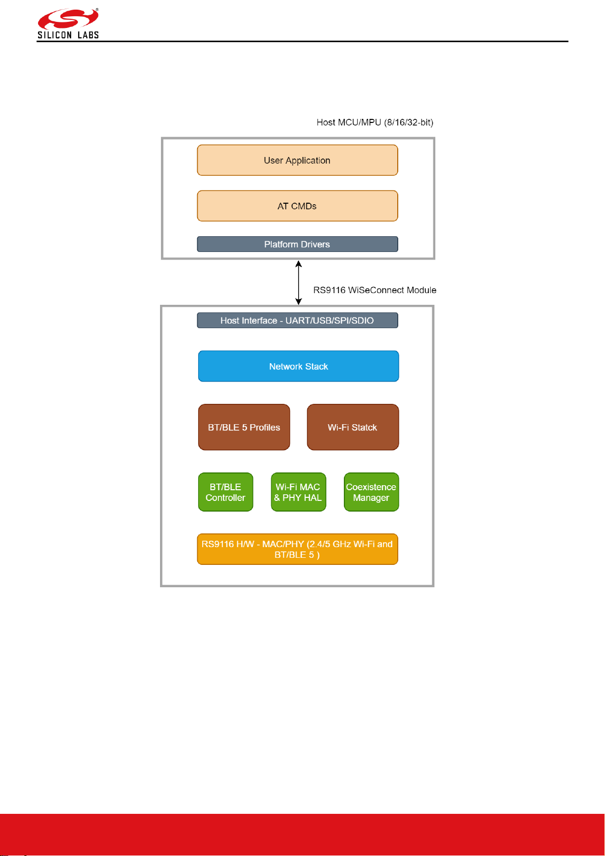
1 Architecture
The following figure depicts the overall architecture of the RS9116-WiSeConnect:
Figure 1: Architecture Overview for RS9116W
Page 6
RS9116W BLE AT Command Programming Reference Manual
Version 2.1
silabs.com | Building a more connected world. 6 | Page
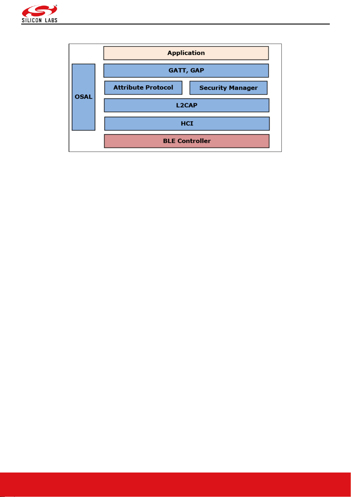
Bluetooth Software Architecture
Figure 2: Bluetooth Software Architecture
Application
Application layer launches Bluetooth stack and uses commands to access various profiles on remote Bluetooth
devices over the network.
Profiles
There are several Bluetooth profiles defined in the Bluetooth specification. Currently Generic Attribute Profile (GATT)
and Generic Access Profile (GAP) profiles are supported. Framework to develop new profiles is provided and new
profiles will be added.
Bluetooth Core
The Bluetooth core contains following higher layers of stack.
• SMP
• ATT
• L2CAP
• BLE Controller
• SMP is a security management protocol which provides services like pairing and key distribution.
• ATT (Attribute Protocol) provides a server to expose attribute values.
• L2CAP (Logical Link Control and Adaption Protocol) provides connection-oriented and connection less data
services to upper layer protocols with data packet size upto 64KB in length.
• L2CAP performs the segmentation and reassembling of I/O packets from the baseband Controller.
• BLE Controller which includes link controller layers.
OS Abstraction Layer
This layer abstracts RTOS services (semaphores, mutexes and critical sections) that are used by the whole stack and
the applications. The stack, which is designed in an RTOS-independent manner, can be used with any RTOS by
porting this layer. It is also possible to use the Bluetooth stack standalone without RTOS.
Page 7

RS9116W BLE AT Command Programming Reference Manual
Version 2.1
silabs.com | Building a more connected world. 7 | Page
2 Bootloader
This section briefs about features that are supported by the Network and Security Processor (NWP) bootloader.
Basic Features
• Load default firmware
• Load selected firmware
• Upgrade firmware from host
• Selecting default images
• Enable / Disable host interaction bypass
• Support for multiple host interfaces (SDIO / SPI / UART / USB / USB-CDC)
• Firmware integrity check
• Upgrading keys
• JTAG selection
The RS9116W supports two Boot loading modes:
1. Host Interaction (Non-bypass) Mode:
a. In this mode host interacts with the bootloader and gives boot up options (commands) to configure
different boot up operations.
b. The host tells the module what operations it has to perform based on the selections made by the user.
2. Bypass Mode:
a. In this mode boot-loader interactions are completely bypassed and uses the stored boot-up configurations
(which are selected in host interaction mode) & loads default firmware image in the module.
b. This mode is recommended for final production software to minimize the boot up time.
Host Interaction Mode
In this mode, host interaction varies based on host interface. Host interactions in SPI / USB and UART / USB-CDC
are different. In UART & USB-CDC boot up options are menu based and in SPI / USB it uses command exchanges.
The details are explained in the below section.
Host Interaction Mode in UART / USB-CDC
This section explains the host interaction mode in UART / USB CDC mode.
Startup Operation
After powering up, Host is required to carry out ABRD (Auto Baud Rate Detection) operation and after successful
ABRD, the module displays menu of boot up options to host. Host needs to select the appropriate option.
Note:
On powerup, bootloader checks the integrity of the bootup options. If the integrity fails, it computes the integrity
from backup. If integrity passes, it copies the backup to the actual location. If the integrity of the backup options
also fails, the bootup options are reset/cleared. In either of the cases, bootloader bypass is disabled, or
corresponding error messages are given to host. In case of integrity failure and when the backup integrity check
passes, "LAST CONFIGURATION NOT SAVED" message is displayed. When backup integrity also fails,
“BOOTUP OPTIONS CHECKSUM FAILED" is displayed before displaying the bootup options.
Hyper Terminal Configuration
RS9116W uses the following UART interface configuration for communication:
Baud Rate: The following baud rates are supported by the module: 9600 bps, 19200 bps, 38400 bps, 57600 bps,
115200 bps, 230400 bps, 460800 bps, 921600 bps.
Data bits: 8
Parity: None
Stop bits: 1
Flow control: None
Page 8
RS9116W BLE AT Command Programming Reference Manual
Version 2.1
silabs.com | Building a more connected world. 8 | Page
Before the module is powered up, follow sequence of steps as given below:
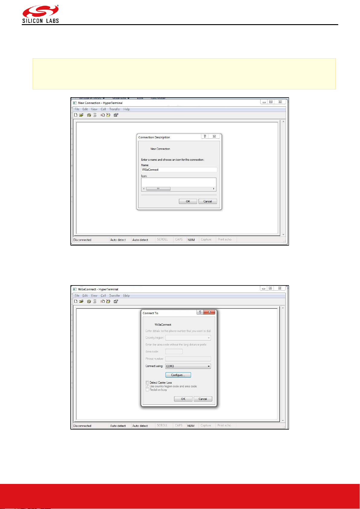
• Open HyperTerminal and enter any name in the "Name" field. After this, click "OK" button. Here,
"WiSeConnect" is entered as shown below:
Note:
Default baud rate of the module is 115200.
Figure 3: HyperTerminal Name field Configuration
• After clicking "OK", the following dialog box is displayed as shown in the figure below.
Figure 4: HyperTerminal COM Port Field Configuration
In the "Connect using" field, select appropriate com port. In the figure above COM3 is selected. Click "OK" button.
• After clicking "OK" button the following dialog box is displayed as shown in the figure below.
Page 9
RS9116W BLE AT Command Programming Reference Manual
Version 2.1
silabs.com | Building a more connected world. 9 | Page
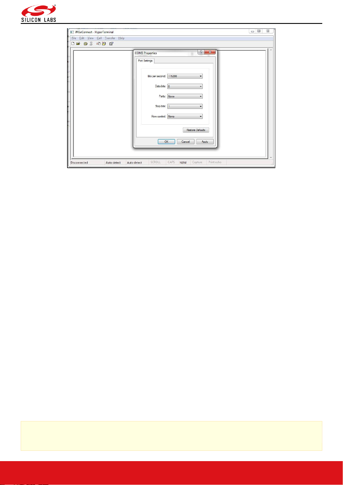
Figure 5: HyperTerminal Baud Rate Field Configuration
Set the following values for different fields in figure 2-3 as given below.
• Set baud rate to 115200 in "Bits per second" field.
• Set Data bits to 8 in "Data bits" field.
• Set Parity to none in "Parity" field.
• Set stop bits to 1 in "Stop bits" field.
• Set flow control to none in "Flow control" field.
• Click "OK" button after entering the data in all the fields.
Auto Baud Rate Detection (ABRD)
The RS9116 automatically detects the baud rate of the Host's UART interface by exchanging some bytes. The Host
should configure the UART interface for the following parameters for ABRD detection.
RS9116 uses the following UART interface configuration for communication:
Baud Rate: The following baud rates are supported: 9600 bps, 19200 bps, 38400 bps, 57600 bps, 115200 bps,
230400 bps, 460800 bps, 921600 bps.
Data bits: 8
Stop bits: 1
Parity: None
Flow control: None
To perform ABRD on the RS9116W, the host must follow the procedure outlined below.
1. Configure the UART interface of the Host at the desired baud rate.
2. Power on the board.
3. The Host, after releasing the module from reset, should wait for 20 ms for initial boot-up of the module to complete
and then transmit 0x1C at the baud rate with which its UART interface is configured. After transmitting '0x1C' to
the module, the Host should wait for the module to transmit 0x55 at the same baud rate.
4. If the '0x55' response is not received from the module, the host has to re-transmit 0x1C, after a delay of 200ms.
5. After finally receiving '0x55', the host should transmit '0x55' to the module. The module is now configured with the
intended baud rate.
Note:
Performing ABRD in host interaction mode is must for USB CDC mode.
Page 10
RS9116W BLE AT Command Programming Reference Manual
Version 2.1
silabs.com | Building a more connected world. 10 | Page
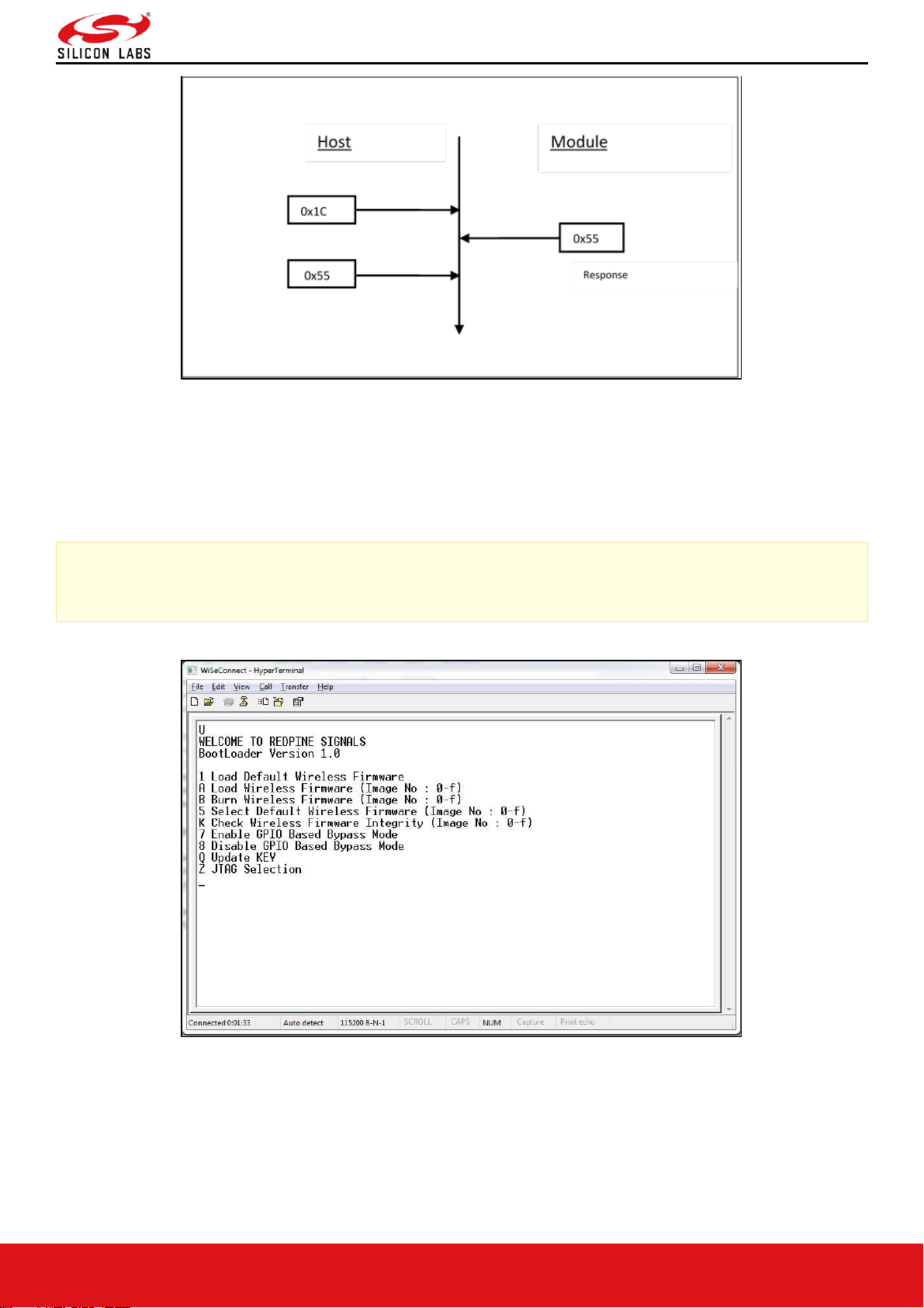
Figure 6: ABRD Exchange Between Host and Module
Below are the bootup options, firmware upgrade and firmware loading procedures for the product.
Start up messages on power-up
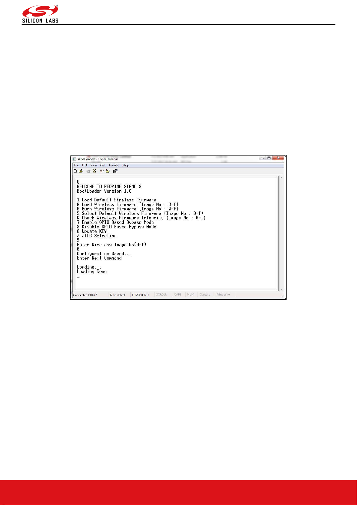
After powering up the module and performing ABRD you will see a welcome message on host, followed by boot up
options:
Note:
Windows HyperTerminal is used to demonstrate boot up / upgrade procedure.
Figure 7: UART / USB-CDC Welcome Message
Loading the default wireless firmware in the module
To load the default firmware flashed onto the module, choose Option 1: "Load Default Wireless Firmware ".
Load Default Wireless Firmware
• After welcome message is displayed as shown in the above figure, select option 1 "Load Default Wireless
Firmware " for loading image.
Page 11
RS9116W BLE AT Command Programming Reference Manual
Version 2.1
silabs.com | Building a more connected world. 11 | Page
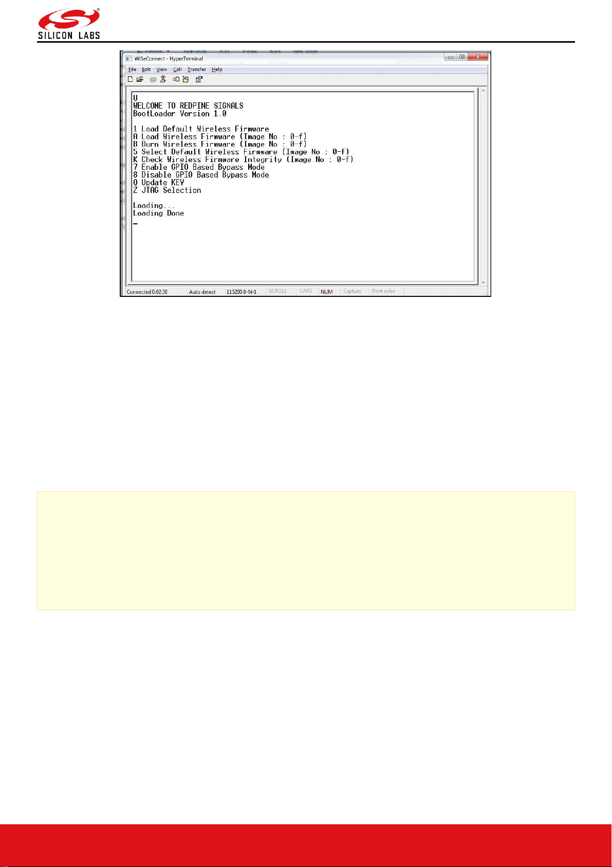
Figure 8: UART / USB-CDC Default Firmware Loaded
To load the selected firmware (from flash) onto the module, choose Option A: "Load Wireless Firmware (Image No: 0f)".
Load Wireless Firmware
• After welcome message is displayed as shown in the above figure, select option A "Load Wireless Firmware
(Image No: 0-f)" for loading Image.
• In response to the option A, Module asks to enter image number.
• Select the image number to be loaded from flash.
• After successfully loading the default firmware, "Loading Done" message is displayed.
• After firmware loading is completed, module is ready to accept commands.
Note:
1. To use host bypass mode user has to select one of the images as default image by selecting options 5
(Select Default Wireless Firmware).
2. In Host interaction mode if there is no option selected after bootup menu for 20 seconds then bootloader will
load selected Wireless default image.
3. If valid firmware is not present, then a message prompting "Valid firmware not present" will be displayed.
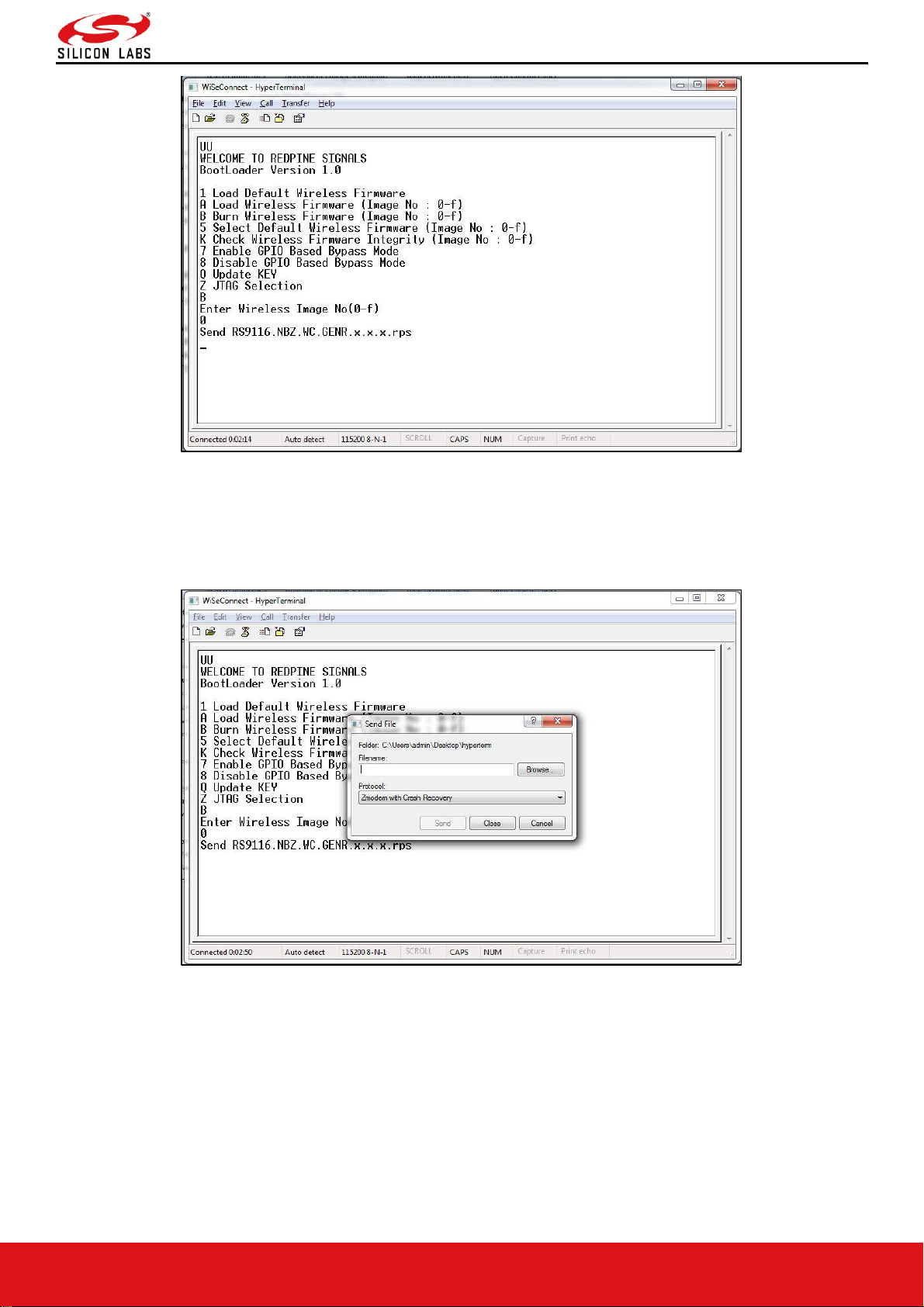
Firmware Upgradation
After powering up the module, a welcome message is displayed.
Upgrade NWP firmware Image
• After the welcome message is displayed, select option B “Burn Wireless Firmware (Image No: 0-f)" to upgrade
Wireless Image.
• The message "Enter Wireless Image No (0-f)"
• Then select the Image no to be upgraded.
• The message "Send RSXXXXX.NBZ.WC.GENR.x.x.x.rps" should appear as shown in the figure below.
Page 12
RS9116W BLE AT Command Programming Reference Manual
Version 2.1
silabs.com | Building a more connected world. 12 | Page
Figure 9: Firmware Upgrade File Prompt Message
• In the "File" menu of HyperTerminal, select the "send file" option. A dialog box will appear as shown in the figure
below. Browse to the path where "RS9116.NBZ.WC.GENR.X.X.X.rps" is located and select Kermit as the protocol
option. After this, click the "Send" button to transfer the file.
Figure 10: Firmware Upgrade File Selection Message
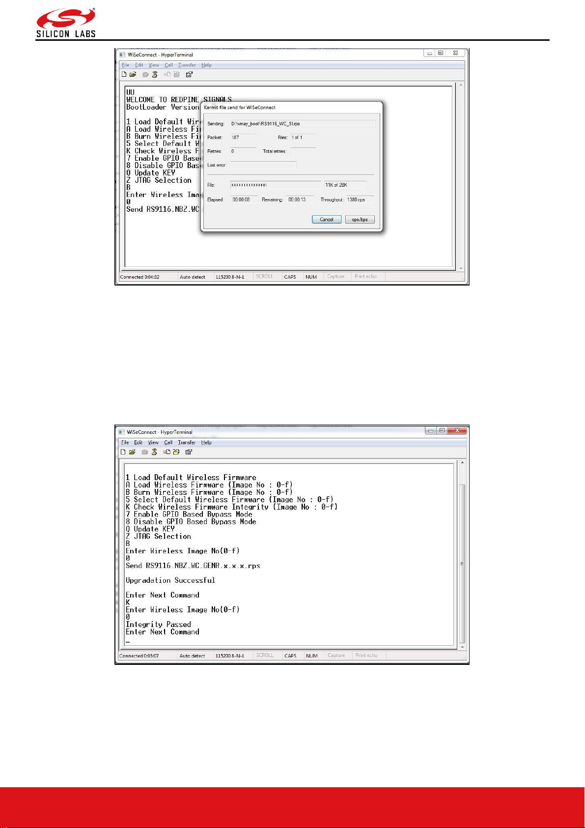
• The dialog box message is displayed while file transfer is in progress as shown in the figure below:
Page 13
RS9116W BLE AT Command Programming Reference Manual
Version 2.1
silabs.com | Building a more connected world. 13 | Page
Figure 11: Firmware Upgrade File Transfer Message
• After successfully completing the file transfer, module computes the integrity of the image and displays
"Upgradation Failed, re-burn the image" in the case of failure. Module displays "Upgradation Failed and default
image invalid, Bypass disabled" in the case of both failure and corruption of the default image.
• In the case of success, module checks if bootloader bypass is enabled and computes the integrity of the default
image selected. If the integrity fails, it sends "Upgradation successful, Default image invalid, gpio bypass
disabled". If integrity passes or gpio bypass is not enabled, it sends "Upgradation Successful" message on
terminal as shown in the figure below.
Figure 12: Firmware Upgrade Completion Message
• At this point, the upgraded firmware image is successfully flashed to the module.
• User can again cross check the integrity of the Image by selecting the Option K " Check Wireless Firmware
Integrity (Image No: 0-f)" for Wireless Image.
• Follow the steps mentioned in the section Loading the Default Wireless Firmware in the Module to load the
firmware from flash, select Option 1 from the above shown figure.
Page 14
RS9116W BLE AT Command Programming Reference Manual
Version 2.1
silabs.com | Building a more connected world. 14 | Page
• The module is ready to accept commands from the Host.
Bypass Mode in UART / USB-CDC
Making Default Wireless Firmware Selection
With this option host can select the default firmware image to be loaded.
Selecting a valid image as the default image
• After the welcome message is displayed, host can select option 5, “Select Default Wireless Firmware (Image No:
0-f)".
• The message "Enter Wireless Image No (0-f)"
• Then select the image no.
• It is better to check the integrity of image before selecting it as default image.
• When default image is selected, module checks for the validity of the image selected and displays "Configuration
saved".
Figure 13: Making Image no - 0 as Default Image
Enable/Disable GPIO Based Bypass Option
This option is for enabling or disabling the GPIO bootloader bypass mode.
Enabling the GPIO Based Bypass Mode
• If you select option 7, GPIO based Bootloader bypass gets enabled.
• When this option is selected, module checks for the validity of the image selected and displays "Configuration
saved" if valid.
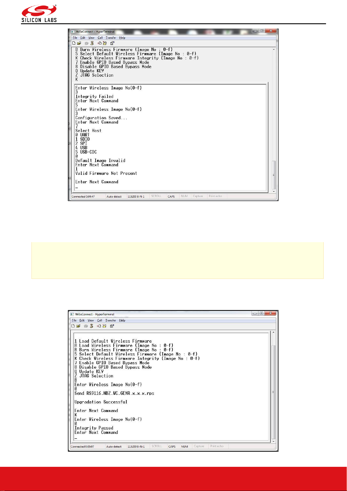
• If valid default image is not present, then a message saying "Default image invalid" will be displayed.
• Once enabled, from next bootup, Bootloader will latch the value of LP_WAKEUP. If asserted, it will bypass the
whole boot loading process and will load the default firmware image selected.
• After the welcome message is displayed, select option 5, “Select Default Wireless Firmware (Image No : 0-f)".
• The window will display "Enter Wireless Image No. (0-f)".
• Select the required image no.
• It is better to check the integrity of image before selecting it as default Image.
• When default image is selected, the module checks for the validity of the image selected and displays
"Configuration saved".
Page 15
RS9116W BLE AT Command Programming Reference Manual
Version 2.1
silabs.com | Building a more connected world. 15 | Page
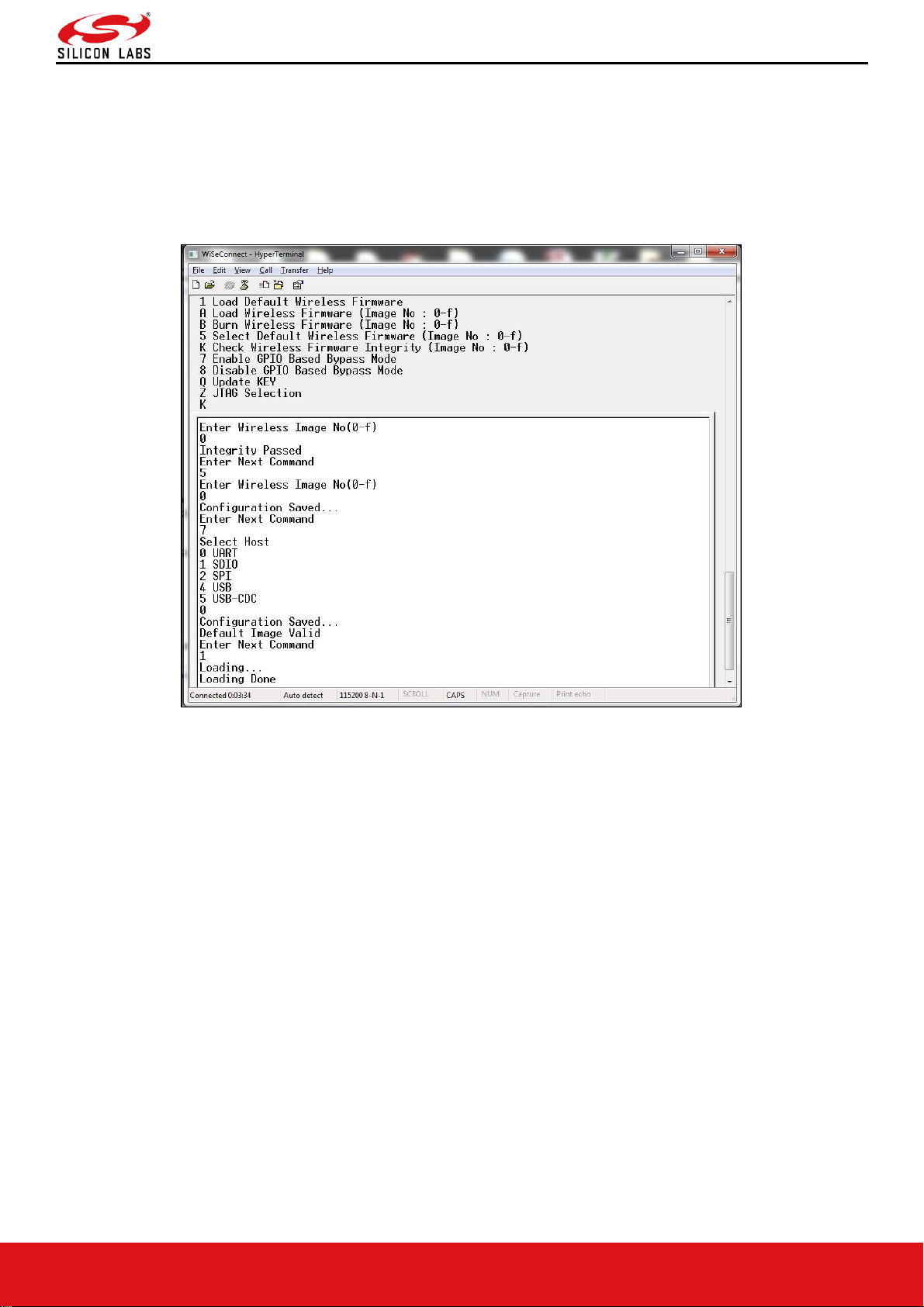
• After this, select option 7 "Enable GPIO Based Bypass Mode".
• The module responds to select the host interface in Bypass mode ( 0 - UART , 1 - SDIO , 2 - SPI , 4 - USB , 5 -
USB-CDC).
• Select the required interface.
If the default image is valid, then it enables GPIO Bypass mode, otherwise it will not enable the GPIO Bypass mode.
Figure 14: Enabling the GPIO-based Bypass Mode; Valid Default Firmware
Page 16
RS9116W BLE AT Command Programming Reference Manual
Version 2.1
silabs.com | Building a more connected world. 16 | Page
Figure 15: Enabling the GPIO-based Bypass Mode; Invalid Firmware
Disabling the GPIO Based Bypass Mode
• If host selects option 8, GPIO based bypass gets disabled.
Note:
GPIO-15 needs to be de-asserted on power up to move to host interaction mode, to select bootup options
like disable Bypass mode or to change default image.
Check Integrity of the Selected Image
This option enables user to check whether the given image is valid or not. When this command is given, bootloader
asks for the image for which integrity has to be verified as shown in figure below.
Figure 16: Integrity Check Passed
Page 17

RS9116W BLE AT Command Programming Reference Manual
Version 2.1
silabs.com | Building a more connected world. 17 | Page
Other Operations
This section contains additional, less frequently used bootloader options.
Update KEY
Note:
This feature is not enabled in current release.
JTAG Selection
Note:
This feature is not enabled in current release.
Page 18

RS9116W BLE AT Command Programming Reference Manual
Version 2.1
silabs.com | Building a more connected world. 18 | Page
3 Host Interfaces
RS9116 WiSeConnect Module supports SPI, USB, UART and SDIO for interfacing to host. This section describes
UART interface in detail including the supported features, protocols and commands.
Only UART and USB-CDC interfaces are supported in AT mode.
Note:
USB and SDIO interfaces are currently not supported.
3.1 UART Interface
This section describes RS9116-WiSeConnect UART interface, including the commands and processes to operate the
module via UART.
UART on the RS9116-WiSeConnect is used as a host interface to configure the module to send and receive data.
Features
• Supports hardware (RTS/CTS) flow control.
• Supports following list of baud rates,
o 9600 bps
o 19200 bps
o 38400 bps
o 57600 bps
o 115200 bps
o 230400 bps
o 460800 bps
o 921600 bps
Note:
For baud rates greater than 115200, it is mandatory to enable UART hardware flow control.
Hardware Interface
RS9916W uses TTL serial UART at an operating voltage of 3.3V.
Host UART device must be configured with the following settings:
• Data bits - 8
• Stop bits - 1
• Parity - None
• Flow control - None
Software Protocol
AT+ command mode
This section explains the procedure that the host needs to follow in order to send Wi-Fi commands frames to the
module and to receive responses from the module in AT+ command mode.
TX Operation
The Host uses TX operations:
1. To send management commands to the module from the Host.
Page 19
RS9116W BLE AT Command Programming Reference Manual
Version 2.1
silabs.com | Building a more connected world. 19 | Page
2. To send actual data to the module which is to be transmitted onto the air.
3. If the host receives error code indicating packet dropped, the host has to wait for a while and send the next
command /data.
4. The host should send next data packet only if it receives "OK<number of bytes sent>" response for the previous
one.
Rx Operation
The RS9116W responds with either an 'OK' or 'ERROR' string, for Management or Data frames along with a result or
error code.
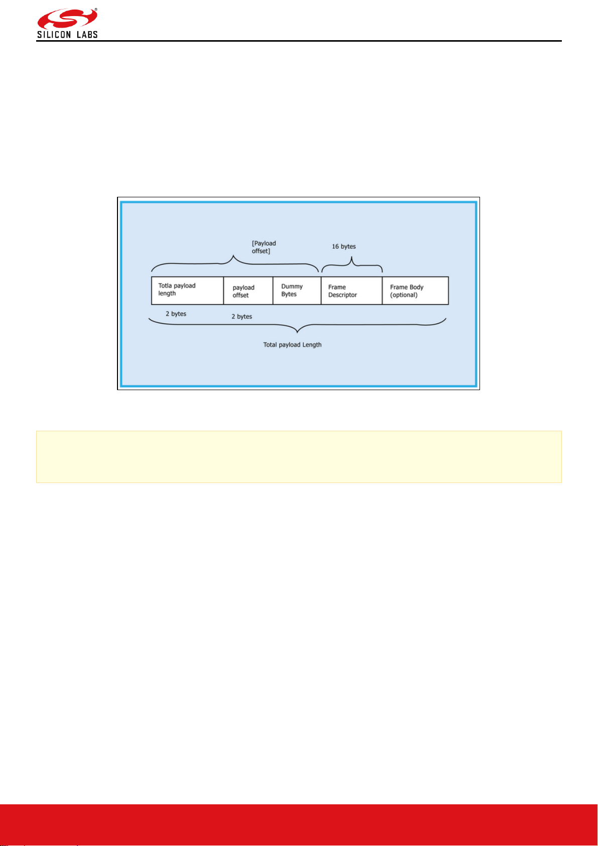
The module sends the response/received data to Host in a format as shown below:
Figure 17: RX Frame Format
Note:
If Payload offset is 'x', 'x-4' dummy bytes will be added before Frame Descriptor.
The host should follow the steps below to read the frame from the Module:
Read 4 bytes using Frame read.
1. Decode Total payload length and payload offset.
2. Read remaining payload by sending Frame to read with (total payload length – 4 bytes), discard Dummy bytes
and then decode Frame descriptor and Frame Body.
Page 20

RS9116W BLE AT Command Programming Reference Manual
Version 2.1
silabs.com | Building a more connected world. 20 | Page
4 Command Mode Selection
This section describes AT command mode or Binary mode selection in UART and USB-CDC.
After bootloader interaction, the module issues "Loading Done" string in ASCII format to host. After receiving "Loading
Done", based on first command received from the host, the module selects command mode.
The module reads first 4 bytes, if it matches with "AT+R", it configures AT command mode otherwise Binary mode is
configured. Once mode is configured, it will remain in same mode until next reset or power cycle.
There is an option in bootloader to select AT mode or binary mode.
Note:
"AT+R" is not case sensitive.
Page 21
RS9116W BLE AT Command Programming Reference Manual
Version 2.1
silabs.com | Building a more connected world. 21 | Page
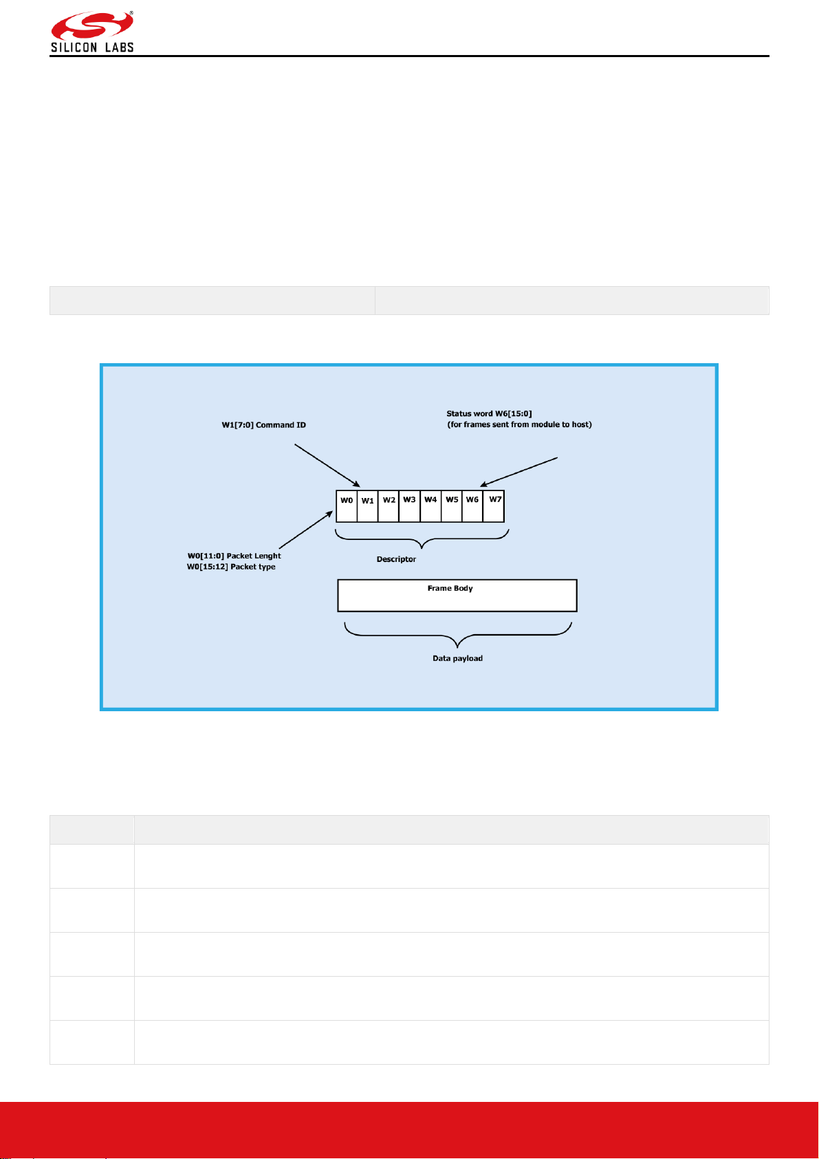
5 Command Format
• This section explains the general command format, commands should be sent to the module in the specified
format.
• Format is same for both Classic and LE modes.
• Commands are sent to the module and responses are read from the module using frame write/frame read (as
mentioned in the preceding sections), these commands are called as command frames.
• The format of the command frames is divided into two parts:
a. Frame descriptor
b. Frame Body (Frame body is often called as Payload)
Frame Descriptor (16 bytes)
Frame Body (multiples of 4 bytes)
Command frame format is shown below. This description is for a Little-Endian System.
Figure 18: Command Frame Format
The following table provides the general description of the frame descriptor.
Table 1: Frame Descriptor
Word
Frame Descriptor
Word0
W0[15:0]
Bits [11:0] – Length of the frame
Bits [15:12] – 2(indicates Bluetooth packet).
Word1
W1[15:0]
Bits [15:0] – Packet type
Word2
W2[15:0]
Reserved
Word3
W3[15:0]
Reserved
Word4
W4[15:0]
Reserved
Page 22

RS9116W BLE AT Command Programming Reference Manual
Version 2.1
silabs.com | Building a more connected world. 22 | Page
Word
Frame Descriptor
Word5
W5 [15:0]
Reserved
Word6
W6 [15:0]
1. (0x0000) when sent from host to module.
2. When sent from module to host (as response frame), it contains the status.
Word7
W7 [15:0]
Reserved
Three types of frames will get exchanged between the module and the host.
1. Request/Command frames - These are sent from Host to Module. Each Request/ Command has an associated
response with it.
2. Response frames – These are sent from Module to Host. These are given in response to the previous
Request/Command from the Host. Each command has a single response.
3. Event frames – These are sent from Module to Host. These are given when there are multiple responses for a
Request/ Command frame. There is Asynchronous message to be sent to host.
The following are the types of frame requests and responses and the corresponding codes. The commands are
different for both Classic and LE modes. The below Table lists the Command, Response and Event frames in LE
mode.
In both the modes, the corresponding code is to be filled in W1 [15:0] mentioned in the Table above.
Table 2: Types of Frame Requests and Responses and the Corresponding Codes
Command
Command ID
Set Local Name
0x0001
Get Local Name
0x0002
Get RSSI
0x0005
Get Local BD Address
0x0007
Advertise
0x0075
Scan
0x0076
Connect
0x0077
Disconnect
0x0078
Query Device State
0x0079
Connection parameter update
0x007A
Start Encryption
0x007B
SMP Pair Request
0x007C
SMP Response
0x007D
SMP Passkey
0x007E
Query Profiles list
0x007F
Query Profile
0x0080
Query Characteristic Services
0x0081
Query Include Services
0x0082
Read Characteristic Value by UUID
0x0083
Page 23

RS9116W BLE AT Command Programming Reference Manual
Version 2.1
silabs.com | Building a more connected world. 23 | Page
Command
Command ID
Query Attribute Descriptor
0x0084
Query Attribute Value
0x0085
Query Multiple Attribute Values
0x0086
Query Long Attribute Values
0x0087
Set Attribute Value
0x0088
Set Attribute Value No Ack
0x0089
Set Long Attribute Value
0x008A
Set Prepare Long Attribute Value
0x008B
Execute Long Attribute Value Write
0x008C
Initialize BLE module
0x008D
De-initialize BLE module
0x008E
Antenna Select
0x008F
Add New Service
0x0092
Add New Attribute
0x0093
Set local attribute value
0x0094
Get local attribute value
0x0095
Notify request
0x0096
Set advertise data
0x009C
Get LE ping timeout
0x00A1
Set LE ping timeout
0x00A2
Set Random Address
0x00A3
Data Encrypt
0x00A4
GATT Read
0x00A5
Scan Response
0X00A8
White List
0X00AA
Remove Service
0X00AB
Remove Attribute
0X00AC
Resolvlist
0X00AD
Get Resolvlist Size
0X00AE
Set Resolution Enable
0X00AF
Read Phy
0X00B0
Set Phy
0X00B1
Set Data Length
0x00B2
Read Data Length
0x00B3
Set Privacy Mode
0x00B4
Page 24

RS9116W BLE AT Command Programming Reference Manual
Version 2.1
silabs.com | Building a more connected world. 24 | Page
Command
Command ID
CBFC Connection Request
0x00B5
CBFC Connection Response
0x00B6
CBFC Tx Data
0x00B7
CBFC Disconnect
0x00B8
LE LTK Request Reply
0x00BA
Rx Test Mode
0x00BB
Tx Test Mode
0x00BC
End Test Mode
0x00BD
Vendor Specific
0x00BE
PER Tx Mode
0x00BF
PER Rx Mode
0x00C0
Profiles Async Request
0x00F2
Profile Async Request
0x00F3
Get char services Async
0x00F4
Get Include services Aync
0x00F5
Read char value by UUID Async
0x00F6
Get attribute Async
0x00F7
Get Descriptor value async
0x00F8
Get multiple values Async
0x00F9
Get Long desc values Async
0x00FA
Set desc value Async
0x00FB
Set prepare write Async
0x00FC
Execute Long desc write Async
0x00FD
Table 3: Response IDs in BLE Mode
Response
Response ID
Card Ready
0x0505
Set Local Name
0x0001
Get Local Name
0x0002
Get RSSI
0x0005
Get Local BD Address
0x0007
Advertise
0x0075
Scan
0x0076
Connect
0x0077
Disconnect
0x0078
Page 25

RS9116W BLE AT Command Programming Reference Manual
Version 2.1
silabs.com | Building a more connected world. 25 | Page
Response
Response ID
Query Device State
0x0079
Connection parameter update
0x007A
Start Encryption
0x007B
SMP Pair Request
0x007C
SMP Response
0x007D
SMP Passkey
0x007E
Query Profiles list
0x007F
Query Profile
0x0080
Query Characteristic Services
0x0081
Query Include Services
0x0082
Read Characteristic Value by UUID
0x0083
Query Attribute Descriptor
0x0084
Query Attribute Value
0x0085
Query Multiple Attribute Values
0x0086
Query Long Attribute Values
0x0087
Set Attribute Value
0x0088
Set Attribute Value No Ack
0x0089
Set Long Attribute Value
0x008A
Set Prepare Long Attribute Value
0x008B
Execute Long Attribute Value Write
0x008C
Initialize BLE module
0x008D
Deinitialize BLE module
0x008E
Antenna Select
0x008F
Add New Service
0x0092
Add New Attribute
0x0093
Set local attribute value
0x0094
Get local attribute value
0x0095
Notify Response
0x0096
Indicate value
0x0097
Set advertise data
0x009C
Get le ping timeout
0x00A1
Set le ping timeout
0x00A2
Set Random Address
0x00A3
Data Encrypt
0x00A4
GATT Read
0x00A5
Page 26

RS9116W BLE AT Command Programming Reference Manual
Version 2.1
silabs.com | Building a more connected world. 26 | Page
Response
Response ID
Scan Response
0X00A8
White List
0X00AA
Remove Service
0X00AB
Remove Attribute
0X00AC
Resolvlist
0X00AD
Get Resolvlist Size
0X00AE
Set Resolution Enable
0X00AF
Read Phy
0X00B0
Set Phy
0X00B1
Set Data Length
0x00B2
Read Data Length
0x00B3
Set Privacy Mode
0x00B4
CBFC Connect Request
0x00B5
CBFC Connect Response
0x00B6
CBFC Tx Data
0x00B7
CBFC Disconnect
0x00B8
LE LTK Request Reply
0x00BA
Rx Test Mode
0x00BB
Tx Test Mode
0x00BC
End Test Mode
0x00BD
Vendor Specific
0x00BE
PER Tx Mode
0x00BF
PER Rx Mode
0x00C0
Profiles Async Request
0x00F2
Profile Async Request
0x00F3
Get char services Async
0x00F4
Get Include services Aync
0x00F5
Read char value by UUID Async
0x00F6
Get attribute Async
0x00F7
Get Descriptor value async
0x00F8
Get multiple values Async
0x00F9
Get Long desc values Async
0x00FA
Set desc value Async
0x00FB
Set prepare write Async
0x00FC
Execute Long desc write Async
0x00FD
Page 27

RS9116W BLE AT Command Programming Reference Manual
Version 2.1
silabs.com | Building a more connected world. 27 | Page
Table 4 Event IDs in BLE mode
Event
Event ID
Disconnected
0x1006
GATT Error Response
0x1500
GATT Desc Val Response
0x1501
GATT Primary Service by UUID
0x1502
GATT Read Char Services
0x1503
GATT Read Include Services
0x1504
GATT Read Val by UUID
0x1505
GATT Read Response
0x1506
GATT Read Blob Response
0x1507
GATT Read Multiple Response
0x1508
GATT Primary Service list
0x1509
GATT Write Response
0x150A
GATT Prepare Write Response
0x150B
GATT Execute Write Response
0x150C
Scan Response
0x150E
Connection Status
0x150F
SMP Request
0x1510
SMP Response
0x1511
SMP Passkey
0x1512
SMP Failed
0x1513
GATT Notification
0x1514
GATT Indication
0x1515
Encrypt Status
0x1516
GATT Write
0x1517
LE ping timeout expired
0x1518
Prepare Write
0x1519
Execute Write
0x151A
GATT Read
0x151B
MTU size
0x151C
SMP passkey display
0x151D
Phy Update Complete
0x151E
Data length change event
0x151F
SMP SC Passkey
0x1520
Enhanced Connection Event
0x1521
Page 28

RS9116W BLE AT Command Programming Reference Manual
Version 2.1
silabs.com | Building a more connected world. 28 | Page
Event
Event ID
Directed Advertising Report
0x1522
Security Keys
0x1523
PSM Connection Request
0x1524
PSM Connection Complete
0x1525
PSM Rx Data
0x1526
PSM Disconnect
0x1527
LE LTK Request
0x152A
Connection Update Complete
0x152B
Remote Features
0x152C
BLE More Data Request
0x152D
Page 29

RS9116W BLE AT Command Programming Reference Manual
Version 2.1
silabs.com | Building a more connected world. 29 | Page
6 BLE Commands
This section explains various BLE commands, the parameters they take and their responses. For API prototypes of
these commands, please refer to the API Library Section.
Note:
A command should not be issued by the Host before receiving the response of a previously issued command
from the module.
6.1 Generic Commands
6.1.1 Set Operating Mode
Description:
This is the first command that needs to be sent from the Host after receiving card ready frame from module. This
command configures the module in different functional modes.
Command Format:
AT Mode:
at+rsi_opermode=
<oper_mode>,<feature_bit_map>,<tcp_ip_feature_bit_map>,<custom_feature_bit_map>,<ext_custom_feature_bit_m
ap>,<bt_custom_feature_bit_map>,<ext_tcp_ip_feature_bit_map>,<ble_custom_feature_bit_map>,<ble_custom_ext
_feature_bit_map>,<config_feature_bit_map>\r\n
Note:
If BIT(31) is set to ‘1’ in custom_feature_bitmap
at+rsi_opermode=<oper_mode>,<feature_bit_map>,<tcp_ip_feature_bit_map>,<custom_feature_bitmap><ext_
custom_feature_bit_map>\r\n
if BIT(31) is set to ‘1’ in tcp_ip_feature_bit_map
at+rsi_opermode=<oper_mode>,<feature_bit_map>,<tcp_ip_feature_bit_map>,<custom_feature_bitmap><ext_
tcp_ip_feature_bit_map>\r\n
if BIT(31) is set to ‘1’ in both custom_feature and ext_custom_feature bit maps
at+rsi_opermode=<oper_mode>,<feature_bit_map>,<tcp_ip_feature_bit_map>,<custom_feature_bitmap><ext_
custom_feature_bit_map> <bt_custom_feature_bit_map>\r\n
if BIT(31) is set to 1 in bt_custom_feature_bit_map
at+rsi_opermode=<oper_mode>,<feature_bit_map>,<tcp_ip_feature_
bit_map>,<custom_feature_bitmap><ext_custom_feature_bit_map><bt_custom_feature_bit_map><ext_tcp_ip_
feature_bit_map><ble_custom_feature_bit_map>\r\n
if BIT(31) is set to 1 in ble_custom_feature_bit_map
at+rsi_opermode=<oper_mode>,<feature_bit_map>,<tcp_ip_feature_
bit_map>,<custom_feature_bitmap><ext_custom_feature_bit_map><bt_custom_feature_bit_map><ext_tcp_ip_
feature_bit_map><ble_custom_feature_bit_map>,<ble_custom_ext_feature_bit_map>\r\n
if BIT(31) is set to '1' in both tcp_ip_feature_bit_map and ext_tcp_ip_feature_bit_map
at+rsi_opermode=<oper_mode>,<feature_bit_map>,<tcp_ip_feature_bit_map>,<custom_feature_bitmap><ext_
custom_feature_bit_map><bt_custom_feature_bit_map><ext_tcp_ip_feature_bit_map><ble_custom_feature_bi
t_map>,<ble_custom_ext_feature_bit_map>,<config_feature_bit_map>\r\n
Command Parameters:
Oper_mode(4 bytes):
Sets the mode of operation. oper_mode contains two parts <wifi_oper_mode, coex_mode>. Lower two bytes
represent wifi_oper_mode and higher two bytes represent coex_mode.
oper_mode = ((wifi_oper_mode) | (coex_mode << 16))
Page 30

RS9116W BLE AT Command Programming Reference Manual
Version 2.1
silabs.com | Building a more connected world. 30 | Page
Note:
please refer to RS9116W Wi-Fi AT Command Programming Reference Manual.pdf at
https://docs.silabs.com/rs9116 for more details on WLAN and co-existence of other protocols with WLAN. In
BTLE mode, BT mode needs to be enabled as well.
Following table represents possible BLE coex modes supported (WLAN is supported only in RS9116 WiSeConnect):
8
Dual Mode (Bluetooth and BLE)
12
BLE mode
* Will be supported in future releases.
Table 5-1: BLE Coex Modes Supported
Note:
1. If coex mode is enabled in opermode command, then BT / BLE protocol will start and give corresponding card
ready in parallel with opermode command response (which will be handled by corresponding application).
2. BT card ready frame is described in RS9116W BT Classic AT Command Programming Reference
Manual.pdf at https://docs.silabs.com/rs9116, BLE card ready frame is described in RS9116W BLE AT
Command Programming Reference Manual.pdf at https://docs.silabs.com/rs9116.
3. Feature selection utility is provided in the package. WiSeConnect device supports the selected features
combination only if it is feasible as per the RSXXXXX_TCPIP_Feature_Selection_vX.xlsx
custom_feature_bit_map(4 bytes):
This bitmap is used to enable following BT/BLE custom features:
BIT[11]: To Enable Packet Pending Indication(wake on wireless) in UART mode
1 - Enable
0 – Disable
BIT[29]: To Enable IAP support in BT mode
1 - Enable
0 – Disable
BIT[31]: This bit is used to validate extended custom feature bitmap.
1 – Extended feature bitmap valid
0 – Extended feature bitmap is invalid
BIT[0:1], BIT[3:4], BIT[7], BIT[21], BIT[30]: Reserved, should be set to all '0'.
If opermode is 8 (PER mode is selected) - feature_bit_map, tcp_ip_feature_bit_map and custom_feature_bit_map can
be ignored or not valid. Set to zero.
ext_custom_feature_bit_map(4 bytes):
This feature bitmap is an extension of custom feature bitmap and is valid only if BIT[31] of custom feature bitmap is
set. This enables the following feature.
BIT[0]: To enable antenna diversity feature.
1 – Enable antenna diversity feature
0 – Disable antenna diversity feature
BIT[1]:This bit is used to enable 4096 bit RSA key support
1 – Enable 4096-bit RSA key support
0 – Disable 4096-bit RSA key support
This bit is required to set for 4096-bit RSA key support. If key size is 4096-bit, module will use a software
routine for exponentiation, so connection time will increase.
BIT[3]: This bit is used to enable SSL certificate with 4096-bit key support
Page 31

RS9116W BLE AT Command Programming Reference Manual
Version 2.1
silabs.com | Building a more connected world. 31 | Page
1 – Enable 4096-bit key support for SSL sockets
0 – Disable 4096-bit key support for SSL sockets
If this bit is enabled, then connected client who is in power save may miss the packet.
BIT[5]: This bit is used to enable Pre-authentication Support.
1 – Enable Pre-authentication Support
0 – Disable Pre-authentication Support
BIT[6]: This bit is used to enable 40MHZ Support
1 – Enable 40MHZ Support
0 – Disable 40MHZ Support
(BIT[20] | BIT[21]) -This bit is used to configure the 384k mode.
Note:
It is mandatory to use 384k mode for all use-cases.
1- Enable
0-Disable
BIT[31]: This bit is used to validate bt and ble feature bitmap.
1 – BT & BLE feature bitmap valid
0 – BT & BLE feature bitmap is invalid
bt_custom_feature_bit_map(4 bytes):
This bitmap is valid only if BIT[31] of the extended custom feature bit map is set.
BIT[0:1] – HP/LP Chain selection in bt classic
0 - BDR/EDR HP chain
1- BDR HP chain
2- BDR LP chain
BIT[2:14] – reserved
BIT[15] – HFP profile bit enable
1- Enable the HFP profile
0- Disable the HFP profile
BIT[16:19] – reserved for future use
BIT[20:22] – Number of slaves supported by BT
Maximum no of BT slaves: 2
BIT [23] – A2DP profile bit enable
1- Enable the A2DP profile
0- Disable the A2DP profile
BIT [24] – A2DP profile role selection
1- A2DP source
0- A2DP sink
BIT [25] – A2DP accelerated mode selection
1- Enable accelerated mode
0- Disable accelerated mode
BIT [26] – A2DP i2s mode selection
1- Enable i2s mode
0- Disable i2s mode
BIT [27:29] – reserved
BIT[30] – RF Type selection
Page 32

RS9116W BLE AT Command Programming Reference Manual
Version 2.1
silabs.com | Building a more connected world. 32 | Page
1 - Internal Rf Type selection
0 - External Rf Type selection
BIT[31] - Validate ble feature bit map.
1 - valid ble feature bit map
0 - Ignore ble feature bit map
ble_custom_feature_bit_map(4 bytes):
This bitmap is valid only if BIT[31] of bt custom feature bit map is set.
BIT [0:7] – BLE nbr of attributes,
Maximum No of Ble attributes = 80, Please refer to NOTE given below for more info
BIT[8:11] – BLE Nbr of GATT services
Maximum no services - 10, Please refer to NOTE given below for more info
BIT [12:15] – BLE Nbr of slaves
Maximum No of Ble slaves = 8, Please refer to NOTE given below for more info
BIT[16:23] – BLE tx power save index
Give 31 as ble tx power index (eg: 31<<16)
This variable is used to select the ble tx power index value. The following are the possible values.
Default Value for BLE Tx Power Index is 31
The range for the BLE Tx Power Index is 1 to 75 (0, 32 index is invalid)
1 - 31 BLE -0DBM Mode
33 - 63 BLE- 10DBM Mode
64- 75 BLE - HP Mode.
BIT[24:26] – BLE power save options
BLE_DUTY_CYCLING BIT(24)
BLR_DUTY_CYCLING BIT(25)
BLE_4X_PWR_SAVE_MODE BIT(26)
BIT [27:28] - BLE Nbr of masters
Maximum No od BLE Masters = 2, Please refer NOTE given below for more info
BIT[29] - GATT SYNC BIT
0 - Gatt Async
1 - Gatt Sync
BIT[30] - To ensure the RS9113 - RS9116 compatible features
1 - Enable the 9116 compatible features
0 - Enable the 9113 compatible features
BIT[31] -Validate ble custom ext feature bit map.
1 - valid ble custom ext feature bit map
0 - Ignore ble custom ext feature bit map
ble_custom_ext_feature_bit_map(4 bytes):
This bitmap is valid only if BIT[31] of ble custom feature bit map is set.
BIT [0:4] – BLE nbr of Connection Events
BIT[5:12] - BLE nbr of record size in bytes (n)
Note:
Eg: n*16:(n=60, Default 1024 bytes(1K)).
Page 33

RS9116W BLE AT Command Programming Reference Manual
Version 2.1
silabs.com | Building a more connected world. 33 | Page
BIT[13] - GATT INIT
0 - Gatt Init in Firmware
1 - Gatt Init in Host
Note:
If bit bt_custom_feature_bit_map[31] is set:
1. User can enter maximum of 8 BLE slaves.
2. User can enter maximum of 2 BLE masters.
3. Maximum of 10 services in total can exist out of which two services namely GAP and GATT are added by
default. So, if this bitmap has value 10 user can add up to 8 services.
4. Maximum of 80 attributes in total can exist out of which ten attributes of GAP and GATT are added by
default. So, if this bitmap has value 80 user can add up to 70 attributes.
If bit bt_custom_feature_bit_map is not set:
1. Default number of BLE slaves supported is 3.
2. Default number of BLE masters supported is 1.
3. Maximum of 5 services in total can exist out of which two services namely GAP and GATT are added by
default. So, user can add up to 3 services.
4. Maximum of 20 attributes in total can exist out of which ten attributes of GAP and GATT are added by
default. So, user can add up to 10 attributes.
config_feature_bit_map(4 bytes):
This bitmap is valid only if BIT[31] of ext_tcp_ip_feature_bit_map is set.
Config Feature bitmap
Functionality
Bit set
to 0
Bit set
to 1
Note and Info
config_feature_bit_map[0]
To select wakeup indication to host.
If it is disabled UULP_GPIO_3 is
used as a wakeup indication to
host.
If it is enabled UULP_GPIO_0 is
used as a wakeup indication to
host.
Disable
Enable
config_feature_bi_map[1:15]
Reserved
config_feature_bi_map[16]
Active high or low interrupt mode
selection for wake on wireless
operation
If it is disabled active low interrupt is
used in wake on wireless operation.
If it is enabled active high interrupt
is used in wake on wireless
operation.
Disable
Enable
config_feature_bi_map[17:23]
Reserved
Page 34

RS9116W BLE AT Command Programming Reference Manual
Version 2.1
silabs.com | Building a more connected world. 34 | Page
Config Feature bitmap
Functionality
Bit set
to 0
Bit set
to 1
Note and Info
config_feature_bit_map[24:25]
Configurability options for 40MHz
XTAL good time in μs
BIT(25)
BIT(24)
Good
time
0 0 1000
0 1 2000
1 0 3000
1 1 600
These bits are used to select
XTAL good time.
These changes are available
from Release 2.3.0 onwards.
Releases prior to 2.3.0 these
config_feature_bitmap[31:17]
are reserved.
Its only applicable for customers
using chip and not the module.
Please contact support for more
details.
Default value is 1000 μs.
config_feature_bit_map[31:26]
Reserved for LMAC
Note:
32KHz external clock connection and power save pins
As per Silicon Labs datasheet update in May 2019, the 32KHz external clock and the power save pins
connections have changed. To keep SW compatibility between initial design (i.e. first EVKs developed by
Silicon Labs) as well as new designs, there are currently 2 options for connecting the 32KHz external clock and
the power save pins:
Option 1:
External 32KHz clock connection pins: XTAL_32KHZ_P & XTAL_32KHZ_N
Power Save connection pins : HOST_BYP_ULP_WAKEUP & UULP_VBAT_GPIO_3
Option 2:
External 32KHz clock connection pin: UULP_VBAT_GPIO_3
Power Save connection pins : HOST_BYP_ULP_WAKEUP & UULP_VBAT_GPIO_0
As per Silicon Labs datasheet updated in May'2019, Option 2 must be used for External 32KHz external clock
and Power save connections in new designs
Response:
AT Mode:
Result Code
Description
OK
Successful execution of the command
ERROR<Error code>
Failure
Example 1:
To enable wlan and ble operating mode with ble power save index as 31 and 9116 compatible feature enabled.
AT Mode:
at+rsi_opermode=851968,0,1,2147483648,2150629376,3221225472,0,3760128000,2048\r\n
Response:
OK\r\n
bt_loaded\r\n
Example 2:
To enable 7 ble slaves, 5 services and 25 attributes, 30 ble power save index
Page 35

RS9116W BLE AT Command Programming Reference Manual
Version 2.1
silabs.com | Building a more connected world. 35 | Page
Command in AT Mode:
at+rsi_opermode=851968,0,1,2147483648,2150629376,3221225472,0,1996057\r\n
Response:
OK\r\n
bt_loaded\r\n
6.1.2 Query RSSI
Description:
This is used to query RSSI of the connected remote BD device
AT command format:
at+rsibt_getrssi=<BDAddress>?\r\n
Parameter: BDAddress(6 bytes) - BT Address of the connected remote device.
Result Code
Description
OK <rssi value>
Command Success.
ERROR <Error_code>
Command Fail.
Response parameters:
RSSI – RSSI value of the connected remote device.
AT command Ex:
at+rsibt_getrssi=AA-BB-CC-DD-EE-FF?\r\n
Response:
OK 130\r\n
6.1.3 Query Local BD Address
Description:
This is used to query the BD address of the local device
AT command format:
at+rsibt_getlocalbdaddr?\r\n
Result Code
Description
OK <bd_addr>
Command Success with valid response.
ERROR <Error_code>
Command Fail.
Response Parameters:
BDAddress(6 bytes) - BT Address of the local device
AT command Ex:
at+rsibt_getlocalbdaddr?\r\n
Response:
OK AA-BB-CC-DD-EE-FF\r\n
6.1.4 Query BT Stack Version
Description:
This is used to query the Current BT Stack Version.
AT command format:
at+rsibt_getbtstackversion?\r\n
Page 36

RS9116W BLE AT Command Programming Reference Manual
Version 2.1
silabs.com | Building a more connected world. 36 | Page
Result Code
Description
OK <stack version>
Command Success with valid response.
ERROR <Error_code>
Command Fail.
Response Parameters:
stackVersion(10 bytes) - Current Stack Version
AT command Ex:
at+rsibt_getbtstackversion?\r\n
Response:
OK 2.0
6.1.5 BLE PER Transmit
Description:
This command can be given to start the ble transmission.
AT Command format:
at+rsibt_bletransmit=<enable/disable>,<access_addr>,<ble_rate>,<rx_channel_num>,<tx_channel_num>,<scrambler
_seed>,<le_channel_type>,<hopping_type>,<antenna_sel>,<pll_mode>,<rf_type>,<rf_chain>,<pkt_len>,<payload_ty
pe>,<tx_power_index>,<tx_mode>,<inter_packet_gap>,<num_of_packets>\r\n
Parameters:
Access Address: It is a 32-bit address in hexadecimal format, e.g.,00112233
ble_rate: 1Mbps - 1, 2Mbps - 2, 125Kbps - 4, 500Kbps - 8
rx_channel_index: Receive channel index, as per the Bluetooth standard. i.e., 0 to 39
tx_channel_index: Transmit channel index, as per the Bluetooth standard. i.e., 0 to 39
scrambler_seed: Initial seed to be used for whitening. It should be set to ‘0’ in order to disable whitening.
le_channel_type: advertising channel - 0, data channel - 1
hopping_type: no hopping -0, fixed hopping - 1, random hopping - 2
antenna_sel: onchip antenna - 2, u.f.l - 3
pll_mode: PLL_MODE0 – 0, PLL_MODE1 – 1, PLL_MODE2 – 2
rf_type: External RF – 0, Internal RF – 1
rf_chain: WLAN_HP_CHAIN 0, WLAN_LP_CHAIN 1, BT_HP_CHAIN 2, BT_LP_CHAIN 3
pkt_len: Length of the packet, in bytes, to be transmitted. Max pkt_len to be transmitted is 240
payload_type: Type of payload to be transmitted
‘0’ – Payload consists of PRBS9 sequence
‘1’ – Payload consists of all 0x0F’s
‘2’ – Payload consists of all 0x55’s
‘3’ – Payload consists of all PBRS15 sequence
‘4’ – Payload consists of all 0xFF's
‘5’ – Payload consists of all 0x00's
‘6’ – Payload consists of all 0xF0's
‘7’ – Payload consists of all 0xA0's
tx_power_index : Transmit power value should be transmitted.
For the BLE-LP Chain, 1 - 31 - 0DBM Mode, 33-63 - 10DBM Mode.
For BLE-LP Chain tx_power value 0 and 32 are invalid.
tx_mode: Burst mode - 0, Continuous mode - 1
inter_pkt_gap: Number of slots to be skipped between two packets - Each slot will be 1250usec
Page 37

RS9116W BLE AT Command Programming Reference Manual
Version 2.1
silabs.com | Building a more connected world. 37 | Page
no_of_packets: Number of packets to be transmitted. It is valid only when the <tx_mode> is set to Burst mode.
AT command Ex:
at+rsibt_bletransmit=1,71764129,1,10,10,0,1,0,3,0,1,3,240,1,31,0,0,0\r\n(enable/start)
Response:
OK\r\n
6.1.6 BLE PER Receive
Description:
This command can be given to start the ble reception.
AT Command format:
at+rsibt_blereceive=<enable/disable>,<access_addr>,<ble_rate>,<rx_channel_num>,<tx_channel_num>,<scrambler_
seed>,<le_channel_type>,<hopping_type>,<antenna_sel>,<pll_mode>,<rf_type>,<rf_chain>,<ext_data_len_ind>,<loo
p_back_mode>,<duty_cycling>\r\n
Parameters:
Access Address: It is a 32-bit address in hexadecimal format, e.g.,00112233
ble_rate: 1Mbps - 1 ,2Mbps - 2, Long Range (LR) - 4
rx_channel_num: Receive channel index, as per the Bluetooth standard. i.e., 0 to 39
tx_channel_num: Transmit channel index, as per the Bluetooth standard. i.e., 0 to 39
scrambler_seed: Initial seed to be used for whitening. It should be set to ‘0’ in order to disable whitening.
le_channel_type: advertising channel – 0, data channel – 1
hopping_type: no hopping -0, fixed hopping - 1, random hopping - 2
antenna_sel: onchip antenna - 2, u.fl – 3
pll_mode: PLL_MODE0 – 0, PLL_MODE1 – 1, PLL_MODE2 – 2
rf_type: External RF – 0, Internal RF – 1
rf_chain: WLAN_HP_CHAIN 0, WLAN_LP_CHAIN 1, BT_HP_CHAIN 2, BT_LP_CHAIN 3
ext_data_len_ind: 0 – Disable (37 Bytes)
1 – Enable (240 Bytes)
loop_back_mode: Disable – 0, Enable – 1
duty_cycling: powersave_options BIT(7) - BLE-4X Mode, BIT(0) - Duty Cycling Mode
AT command Ex:
at+rsibt_blereceive=1,71764129,1,10,10,0,1,0,3,0,1,3,240,1,0\r\n(enable/start)
Response:
OK\r\n
Appendix
Frequencies and channel Numbers used for Bluetooth LE Mode:
Band (GHz)
Bandwidth (MHz)
Channel
Center Freq (MHz)
2.4 2 0
2402
2.4 2 1
2404
2.4 2 2
2406
2.4 2 3
2408
2.4 2 4
2410
2.4 2 5
2412
Page 38

RS9116W BLE AT Command Programming Reference Manual
Version 2.1
silabs.com | Building a more connected world. 38 | Page
Band (GHz)
Bandwidth (MHz)
Channel
Center Freq (MHz)
2.4 2 6
2414
2.4 2 7
2416
2.4 2 8
2418
2.4 2 9
2420
2.4
2
10
2422
2.4
2
11
2424
2.4
2
12
2426
2.4
2
13
2428
2.4
2
14
2430
2.4
2
15
2432
2.4
2
16
2434
2.4
2
17
2436
2.4
2
18
2438
2.4
2
19
2440
2.4
2
20
2442
2.4
2
21
2444
2.4
2
22
2446
2.4
2
23
2448
2.4
2
24
2450
2.4
2
25
2452
2.4
2
26
2454
2.4
2
27
2456
2.4
2
28
2458
2.4
2
29
2460
2.4
2
30
2462
2.4
2
31
2464
2.4
2
32
2466
2.4
2
33
2468
2.4
2
34
2470
2.4
2
35
2472
2.4
2
36
2474
2.4
2
37
2476
2.4
2
38
2478
2.4
2
39
2480
Page 39

RS9116W BLE AT Command Programming Reference Manual
Version 2.1
silabs.com | Building a more connected world. 39 | Page
6.1.7 PER CW Mode
Description:
This command can be given to enable the Continuous Wave mode transmission.
AT Command format:
at+rsibt_percwmode=<Enable/Disable>\r\n
Parameters:
Disable - 0
Enable - 1
Note:
Need to issue this command after giving the ble transmit command.
6.2 BLE Core Commands
6.2.1 Advertise Local Device
Description:
This is used to expose or advertise about the local device to the remote BT devices.
AT Command format:
at+rsibt_advertise=< Status >,< AdvertiseType >,< FilterType >,<DirectAddrType>,<DirectAddr>,< adv_int_min >,<
adv_int_max >,< own_add_type >,< adv_channel_map >\r\n
Note:
All parameters should be in decimal except DirectAddr, it should be in hexadecimal.
Parameters:
Status (1 byte) – To enable/disable Advertising.
1 – Enable Advertising
0 – Disable Advertising
AdvertiseType (1 byte) –
State
Description
0x80
Connectable undirected
0x81
Connectable directed with high duty cycle
0x82
Scannable undirected
0x83
Non connectable undirected
0x84
Connectable directed with low duty cycle
FilterType (1 byte) –
Filter type
Description
0
Allow Scan Request from Any, Allow Connect Request from Any.
1
Allow Scan Request from White List Only, Allow Connect Request from Any.
2
Allow Scan Request from Any, Allow Connect Request from White List Only.
3
Allow Scan Request from White List Only, Allow Connect Request from White List Only.
Page 40

RS9116W BLE AT Command Programming Reference Manual
Version 2.1
silabs.com | Building a more connected world. 40 | Page
DirectAddrType(1 byte) -
0 – Public address
1 – Random address
DirectAddr(1 byte)- Remote device BD Address
adv_int_min(2 bytes) -
Value
Parameter Description
N = 0xXXXX
Minimum advertising interval for non-directed advertising.
Range: 0x0020 to 0x4000
Default: N = 0x0800 (1.28 second)
Time = N * 0.625 msec
Time Range: 20 ms to 10.24 sec.
adv_int_max(2 bytes) -
Value
Parameter Description
N = 0xXXXX
Minimum advertising interval for non-directed advertising.
Range: 0x0020 to 0x4000
Default: N = 0x0800 (1.28 second)
Time = N * 0.625 msec
Time Range: 20 ms to 10.24 sec.
own_add_type(1 byte) -
Value
Parameter Description
0x00
Public Device Address (default)
0x01
Random Device Address
0x02 – 0xFF
Reserved for future use
adv_channel_map(1 byte)-
Value
Parameter Description
00000000b
Reserved for future use
xxxxxxx1b
Enable channel 37 use
xxxxxx1xb
Enable channel 38 use
xxxxx1xxb
Enable channel 39 use
00000111b
Default (all channels enabled)
AT command Ex:
at+rsibt_advertise=1,128,0,0,0,32,32,0,7\r\n(enable)
Response:
OK\r\n
Note:
For scannable undirected and non-connectable undirected advertising modes, minimum advertising interval
should be 41ms and maximum advertising interval should be 1.28s
6.2.2 Scan
Description: This is used to scan for remote LE advertise devices.
AT Command format:
at+rsibt_scan=< Status >, < Scantype >, < FilterType >,< own_add_type >,< scan_int >,< scan_win >\r\n
Page 41

RS9116W BLE AT Command Programming Reference Manual
Version 2.1
silabs.com | Building a more connected world. 41 | Page
Note:
All Parameters should be in Decimal.
Parameters:
Status (1 byte) – To enable/disable Scanning
1 – Enable Scanning
0 – Disable Scanning
Scantype(1 byte) –
Scan type
Description
0
Passive Scanning
1
Active Scanning
FilterType(1 byte) –
Value
Parameter Description
0
Accept all advertisement packets.
1
Accept only white listed device
advertisement packets.
Scan_int(2 bytes) -
Value
Description
N = 0xXXXX
This is defined as the time interval from when the Controller
started its last LE scan until it begins the subsequent LE scan.
Range: 0x0004 to 0x4000
Default: 0x0010 (10 ms)
Time = N * 0.625 msec
Time Range: 2.5 msec to 10 . 24 seconds
scan_win(2 bytes) -
Value
Description
N = 0xXXXX
The duration of the LE scan. LE_Scan_Window shall be less than
or equal to LE_Scan_Interval
Range: 0x0004 to 0x4000
Default: 0x0010 (10 ms)
Time = N * 0.625 msec
Time Range: 2.5 msec to 10240 msec
own_add_type(1 byte) -
Value
Parameter Description
0x00
Public Device Address (default)
0x01
Random Device Address
0x02 – 0xFF
Reserved for future use
AT command Ex:
at+rsibt_scan=1,0,0,0,100,10\r\n (enable scan)
Response:
OK\r\n
AT command Ex:
at+rsibt_scan=0,0,0,0,100,10\r\n (disable scan)
Response:
Page 42

RS9116W BLE AT Command Programming Reference Manual
Version 2.1
silabs.com | Building a more connected world. 42 | Page
OK\r\n
Note:
In parameters Scan Interval must be greater than scan window.
6.2.3 Connect
Description: This is used to create connection with remote LE device.
AT Command format:
at+rsibt_connect=< AddressType >, < BDAddress >< LeScanInterval >,< LeScanWindow >,< ConnIntervalMin >,<
ConnIntervalMax >,< ConnLatency >,< SupervisionTimeout >\r\n
Parameters:
AddressType(1 byte) – Specifies the type of the address mentioned in BDAdress
0 – Public Address
1 – Random Address
BDAdress(6 bytes) – BD Address of the remote device
le_scan_interval and le_scan_window parameters are recommendations from the Host on how long
(LE_Scan_Window) and how frequently (LE_Scan_Interval) the Controller should scan.
LE_Scan_Interval(2 bytes):
Value
Description
N = 0xXXXX
This is defined as the time interval from when the Controller
started its last LE scan until it begins the subsequent LE scan.
Range: 0x0004 to 0x4000
Time = N * 0.625 msec
Time Range: 2.5 msec to 10.24 seconds
LE_Scan_Window(2 bytes):
Value
Description
N = 0xXXXX
Amount of time for the duration of the LE scan. LE_Scan_Window
shall be less than or equal to LE_Scan_Interval
Range: 0x0004 to 0x4000
Time = N * 0.625 msec
Time Range: 2.5 msec to 10.24 seconds
The conn_interval_min and conn_interval_max parameters define the minimum and maximum allowed connection
interval.
Conn_Interval_Min(1byte):
Value
Description
N = 0xXXXX
Minimum value for the connection event interval. This shall be less than or equal to
Conn_Interval_Max.
Range: 0x0006 to 0x0C80
Time = N * 1.25 msec
Time Range: 7.5 msec to 4 seconds.
0x0000 – 0x0005
and
0x0C81 – 0xFFFF
Reserved for future use
Conn_Interval_Max(2 byte):
Value
Description
N = 0xXXXX
Minimum value for the connection event interval. This shall be greater than or equal to
Conn_Interval_Min.
Range: 0x0006 to 0x0C80
Page 43

RS9116W BLE AT Command Programming Reference Manual
Version 2.1
silabs.com | Building a more connected world. 43 | Page
Value
Description
Time = N * 1.25 msec
Time Range: 7.5 msec to 4 seconds.
0x0000 – 0x0005
and
0x0C81 – 0xFFFF
Reserved for future use
Conn_Latency(2 bytes):
The conn_latency parameter defines the maximum allowed connection Latency.
Value
Description
N = 0xXXXX
Slave latency for the connection in number of connection events.
Range: 0x0000 to 0x01F4
Supervision_Timeout(2 bytes):
The supervision_tout parameter defines the link supervision timeout for the connection.
Value
Description
N = 0xXXXX
Supervision timeout for the LE Link.
Range: 0x000A to 0x0C80
Time = N * 10 msec
Time Range: 100 msec to 32 seconds
0x0000 – 0x0009 and
0x0C81 – 0xFFFF
Reserved for future use
AT command Ex:
at+rsibt_connect=0,B4-99-4C-64-BE-F5,96,32,160,160,0,100\r\n
Response:
OK\r\n
Note:
Reception of the response doesn't mean that Connection with the remote device is completed.
Connection is said to complete after it receives Connection Complete Event. The user is recommended not to
give further commands before receiving the above Event. But the user can give Disconnect even before
Connection Complete Event is received.
6.2.4 Disconnect
Description: This is used to cancel create Connection or disconnect HCI Connection, if already connected.
AT Command format:
at+rsibt_disconnect=<BDAddress>\r\n
Parameters:
BDAdress(6 bytes) – BD Address of the remote device
AT command Ex:
at+rsibt_disconnect=53-41-CC-FF-91-2A\r\n
Response:
OK\r\n
6.2.5 Query Device State
Description: This is used to query state of the local device.
AT Command format:
at+rsibt_getdevstate?\r\n
Page 44

RS9116W BLE AT Command Programming Reference Manual
Version 2.1
silabs.com | Building a more connected world. 44 | Page
Result Code
Description
OK,< state>
Command Success.
ERROR <Error_code>
Command Fail.
Response Parameters:
DeviceState(1 byte) –
Bit
Description
0
Advertise (0-disable/1-enable)
1
scan state (0-disable/ 1-enable)
2
connection initiated (0-not initiated/1-initiated)
3
connected state (0-not connected/1-connected)
AT command Ex:
at+rsibt_getdevstate?\r\n
Response:
OK 8\r\n
6.2.6 Start Encryption
Description: This is used to initiate the Encryption procedure.
AT command Format: at+rsibt_startencrypt=<BDAddress>,<RemoteEDIV>,<RemoteRand>,<RemoteLTK>\r\n
Parameters:
BDAddress(6 bytes) - Remote BD Address.
RemoteEDIV(2 bytes) - Remote device Encryption Diversifier
RemoteRand(8 bytes) - Remote device Random number
RemoteLTK(16 bytes) - Remote device Long Term Key
AT command Ex:
at+rsibt_startencrypt=B4-99-4C-64-BE-
F5,253C,45,B6,53,7A,37,42,85,9D,65,BA,84,DA,CC,56,85,9D,3A,74,3C,45,23,78,4D,3A\r\n
Response:
OK\r\n
6.2.7 SMP Pair Request
Description: This is used to send SMP Pair Request command to the connected remote device.
AT Command format:
at+rsibt_smpreq=<BDAddress>,<IO Capability>\r\n
Parameters:
BDAddress(6 bytes) - Remote BD Address.
IOCapability(1 byte) –
IO Capability type
Description
0
Display Only
1
Display Yes No
2
Keyboard only
3
No input no output
AT command Ex:
Page 45

RS9116W BLE AT Command Programming Reference Manual
Version 2.1
silabs.com | Building a more connected world. 45 | Page
at+rsibt_smpreq=B4-99-4C-64-BE-F5,1\r\n
Response:
OK\r\n
6.2.8 SMP Response
Description: This is used to send SMP response to the SMP request made by the remote device.
AT Command format:
at+rsibt_smpresp=<BDAddress>,<IOCapability>\r\n
Parameters:
BDAddress(6 bytes) - Remote BD Address.
IOCapability (1 byte) –
IO Capability type
Description
0
Display Only
1
Display Yes No
2
Keyboard only
3
No input no output
AT command Ex:
at+rsibt_smpresp=74-04-2B-7A-93-EF,1\r\n
Response:
OK\r\n
6.2.9 SMP Passkey
Description: This is used to send SMP Passkey required to connect with the remote device.
AT Command format:
at+rsibt_smppasskey=<BDAddress>,<Passkey>\r\n
Parameters:
BDAddress(6 bytes) - Remote BD Address.
Passkey(4 bytes) – Passkey to authenticate with the Remote device.
AT command Ex:
at+rsibt_smppasskey=B4-99-4C-64-BE-F5,12345\r\n
Response:
OK\r\n
6.2.10 Initialize BLE Module
Description: This is used to initialize the BLE module
AT Command format:
at+rsibt_btinit\r\n
AT command Ex:
at+rsibt_btinit\r\n
Response:
OK\r\n
Page 46

RS9116W BLE AT Command Programming Reference Manual
Version 2.1
silabs.com | Building a more connected world. 46 | Page
6.2.11 Deinitialize BLE Module
Description: This is used to de-initialize the BLE module.
AT Command format:
at+rsibt_btdeinit\r\n
AT command Ex:
at+rsibt_btdeinit\r\n
Response:
OK\r\n
6.2.12 BT Antenna Select
Description: This is used to select the internal or external antenna of the BT module.
AT Command format:
at+rsibt_btantennaselect=<AntennaVal>\r\n
Parameters:
AntennaVal(1 byte) – To select the internal or external antenna
0 – Internal Antenna.
1 – External Antenna.
AT command Ex:
at+rsibt_btantennaselect=1\r\n
Response:
OK\r\n
6.2.13 BLE Set Advertise Data
Description: This command is used to set the advertise data to expose remote devices.
AT Command format:
at+rsibt_setadvertisedata=<DataLen>,<Data>\r\n
Parameters:
Length (1 byte) – data length. Max advertise data length is 31.
Data (31 bytes) – Actual data
AT command Ex:
at+rsibt_setadvertisedata=8,2,1,6,4,9,72,72,72\r\n
Response: OK\r\n
Note:
Name set in this command will be shown on remote device when remote device scan for advertising device
(except for iOS versions).
Page 47

RS9116W BLE AT Command Programming Reference Manual
Version 2.1
silabs.com | Building a more connected world. 47 | Page
Figure 19: Advertising or Scan Response Data
For more information on this advertising data with types, information is available at following link:
https://www.bluetooth.com/specifications/assigned-numbers/generic-access-profile
6.2.14 BLE Set Scan Response Data
Description:
This command is used to set the scan response data.
AT Command format:
at+rsibt_setscanrspdata=<DataLen>,<Data>\r\n
Parameters:
Length(1 byte) – data length. Max Scan Response data length is 31.
Data(31 bytes) – Actual data
AT command Ex:
at+rsibt_setscanrspdata=8,2,1,6,4,9,72,72,72\r\n
Response:
OK\r\n
Note:
Name set in this command will be shown on remote device when remote device scan for advertising device
(except for iOS versions).
Note:
Controller has default scan response data which enable the flags 2,1,6.
6.2.15 BLE Set LE Ping Timeout
Description: This command is used to set the LE ping timeout.
AT command Format:
at+rsibt_setlepingtimeout=<BDAddress>, <Timeout>\r\n
Page 48

RS9116W BLE AT Command Programming Reference Manual
Version 2.1
silabs.com | Building a more connected world. 48 | Page
Parameters:
BDAddress(6 bytes): Remote BD Address.
Timeout(2 bytes)
Value
Parameter Description
N = 0xXXXX
Maximum amount of time specified between packets authenticated by
a MIC.
Default = 0x0BB8 (30 seconds)
Range: 0x0001 to 0xFFFF
Time = N * 10 msec
Time Range: 10 msec to 655,350 msec
AT command Ex:
at+rsibt_setlepingtimeout=B4-99-4C-64-BE-F5,30000\r\n
Response:
OK\r\n
6.2.16 BLE Get LE Ping Timeout
Description: This command is used to get the LE ping timeout (In milliseconds).
Note:
Currently Get LE ping is not supported.
AT command Format:
at+rsibt_getlepingtimeout=<Connected Remote BD_ADDR>\r\n
AT command Ex:
at+rsibt_setlepingtimeout?\r\n
Response:
OK 30000\r\n
6.2.17 BLE Set Random Device Address
Description:
This command is used by the Host to set the LE Random Device Address in the Controller.
AT command Format:
at+rsibt_setrandadd=<BDAddress>\r\n
Parameters:
BDAddress(6 bytes):
Value
Parameter Description
0xXXXXXXXXXXXX
Random Device Address as defined by Device Address
Return Parameters:
Status:
Value
Parameter Description
0x00
LE_Set_Random_Address command succeeded.
0x01 – 0xFF
LE_Set_Random_Address command failed.
AT command Ex:
at+rsibt_setrandadd= B4-99-4C-64-BE-F5\r\n
Response:
Page 49

RS9116W BLE AT Command Programming Reference Manual
Version 2.1
silabs.com | Building a more connected world. 49 | Page
OK 0\r\n
6.2.18 BLE Data Encrypt
Description: This command is used to encrypt the data.
AT command Format:
at+rsibt_leencrypt=<key>,<data>\r\n
Parameters:
key – key length is 16 Bytes.
Data – Actual data , length is 16 Bytes.
Result Code
Description
OK <EncData>
Command Success.
ERROR <Error_code>
Command Fail.
AT command Ex:
at+rsibt_leencrypt=1,2,3,4,5,6,7,8,9,0,B,C,D,E,F,10, 1,2,3,4,5,6,7,8,9,0,B,C,D,E,F,10\r\n
Response:
OK 10 93 c1 5a e4 a5 db fd 5e c2 4c 61 8a a3 11 28 \r\n
6.2.19 BLE Whitelist
Description: This is used to add a particular BD-Address to the white list.
AT command format: at+rsibt_lewhitelist=<Add/deletebit>,<BDAddress>,<BDAddressType>\r\n
Parameters:
Add/Delete bit(1 byte) – This bit specifies the operation to be done
0 – Clear all entries
1 – Add entry to white list
2 – Delete entry from the white list
BDAddress(6 bytes) – BDAddress of the remote device that needed to be added to white list
BDAddressType(1 byte) – Type of the BDAddress
0- Public Device Address
1 – Random Device Address
ATcommandEx:
at+rsibt_lewhitelist=1,00-23-A7-80-6F-CD,1\r\n
Response:
OK\r\n
6.2.20 BLE Set MTU Size Command
Description: This is used to set the MTU size for the BLE stack.
AT command format: at+rsibt_blesetmtu=<BDAddress>,<MTU Size>\r\n
Parameters:
BDAddress (6 bytes)– BDAddress of the remote device
MTU Size - MTU size for BLE.
ATcommandEx:
at+rsibt_blesetmtu=69-76-4A-4C-13-8C,80\r\n
Response:
OK\r\n
Page 50

RS9116W BLE AT Command Programming Reference Manual
Version 2.1
silabs.com | Building a more connected world. 50 | Page
Note:
By default, MTU size is 240bytes. Until issue this command, MTU size won't be changed from 240bytes.
6.2.21 BLE Set Phy Command
Description: The LE_Set_PHY command is used to set the PHY preferences for the connection identified by the
Connection_Handle.
AT command format:
at+rsibt_setphy=<remotebdaddress>,<all_phy>,<tx_phy>,<rx_phy>,<phy_ options>
Parameters:
BDAddress(6 bytes) – BDAddress of the remote device.
<All_phy>(1 byte)–
BIT(0)-The Host has no preference among the transmitter PHYs supported by the Controller.
BIT(1)-The Host has no preference among the receiver PHYs supported by the Controller.
All other bits are reserved.
< tx_phy >(1 byte)-
BIT(0) - The Host prefers to use the LE 1M transmitter PHY (possibly among others)
BIT(1) - The Host prefers to use the LE 2M transmitter PHY (possibly among others)
BIT(2) - The Host prefers to use the LE Coded transmitter PHY (possibly among others)
BIT(3) – BIT(7) Reserved for future use
<rx_phy>(1 byte) -
BIT(0) - The Host prefers to use the LE 1M receiver PHY (possibly among others)
BIT(1) - The Host prefers to use the LE 2M receiver PHY (possibly among others)
BIT(2) - The Host prefers to use the LE Coded receiver PHY (possibly among others)
BIT(3) – BIT(7) Reserved for future use
<phy_ options>(2 bytes)
0 = the Host has no preferred coding when transmitting on the LE Coded
PHY
1 = the Host prefers that S=2 coding be used when transmitting on the LE
Coded PHY
2 = the Host prefers that S=8 coding be used when transmitting on the LE
Coded PHY
3 = Reserved for future use
ATcommandEx:
at+rsibt_setphy=00-23-A7-00-00-0D,0,1,2,0
Response:
OK\r\n
6.2.22 BLE Read Phy Command
Description: The LE_Read_PHY command is used to read the current transmitter PHY and receiver PHY on the
connection identified by the Connection_Handle.
AT command format: at+rsibt_readphy=<remotebdaddr>
Page 51

RS9116W BLE AT Command Programming Reference Manual
Version 2.1
silabs.com | Building a more connected world. 51 | Page
Parameters:
remotebdaddr(6 bytes) – BDAddress of the remote device.
ATcommandEx:
at+rsibt_readphy=00-23-A7-00-00-0D
Response:
OK, <Remotebdaddr(6 bytes)>,tx_phy,rx_phy\r\n
S.No
Response Parameters
Parameter Description
1
BD ADDR
Remote device Bluetooth Address
2
TX_PHY
0x01 The transmitter PHY for the connection is LE 1M
0x02 The transmitter PHY for the connection is LE 2M
0x03 The transmitter PHY for the connection is LE Coded
All other values Reserved for future use
2
RX_PHY
0x01 The receiver PHY for the connection is LE 1M
0x02 The receiver PHY for the connection is LE 2M
0x03 The receiver PHY for the connection is LE Coded
All other values Reserved for future use
Ex: OK 88-DA-1A-9E-BE-6A,2,2 \r\n
6.2.23 BLE Set Data Length Command
Description: The LE_Set_Data_Length command allows the Host to suggest maximum transmission packet size and
maximum packet transmission time.
AT command format:
At+rsibt_setdatalength=<BDAddress>,<TXOctets><TXTime>\r\n
Parameters:
BDAddress(6 bytes) – BDAddress of the remote device.
TXOctets(2 bytes)– Preferred maximum number of payload octets that the local I Controller should include in a single
Link Layer packet on this connection.
TXTime(2 bytes)-Preferred maximum number of microseconds that the local Controller should use to transmit a single
Link Layer packet on this connection.
ATcommandEx:
at+rsibt_setdatalength =00-23-A7-80-6F-CD,40,330,\r\n
Response:
OK\r\n
6.2.24 BLE Read Maximum Data Length Command
Description: The LE_Read_Maximum_Data_Length command allows the Host to read the Controller's maximum
supported payload octets and packet duration times for transmission and reception.
AT command format:
At+rsibt_readdatalength?
ATcommandEx:
at+rsibt_readdatalength?\r\n
Response:
OK\r\n
Page 52

RS9116W BLE AT Command Programming Reference Manual
Version 2.1
silabs.com | Building a more connected world. 52 | Page
6.2.25 BLE_Resolvlist
Description: The Resolving_List command is used to add/remove/clear one device to the list of address translations
used to resolve Resolvable Private Addresses in the Controller.
AT command format:
at+rsibt_resolvlist=<Process_type>,<address_type>,<peer_address>,<peer_irk>,<local_irk>
Parameters:
<Process_type>
1 = Add
2=Remove
3=Clear Resolvlist.
<AddressType > =
0x00 Public Identity Address
0x01 Random (static) Identity Address
0x02 – 0xFF Reserved for Future Use
<peer_address> = Public or Random (static) Identity address of the peer device
< peer_irk> = IRK of the peer device.
<local_irk> = IRK of the local device.
ATcommandEx:
Example 1:
-- > Add device to resolvlist
at+rsibt_resolvlist=1,0,00-23-A7-00-000D,01,01,01,01,01,01,01,01,01,01,01,01,01,01,01,01,02,02,02,02,02,02,02,02,02,02,02,02,02,02,02,02
Example 2:
-->remove device from resolvlist
at+rsibt_resolvlist=2,<address_type>,<peer_address>
eg:at+rsibt_resolvlist=2,0,00-23-A7-00-00-0D
Example 3:
-->clear resolvlist
at+rsibt_resolvlist=3
Response:
OK\r\n
6.2.26 BLE GetResolvlist Size
Description: The BLE_Read_Resolving_List_Size command is used to read the total number of address translation
entries in the resolving list that can be stored in the Controller.
AT command format:
At+rsibt_ getresolvlistsize?\r\n
ATcommandEx:
at+rsibt_ getresolvlistsize?\r\n
Response:
OK\r\n
6.2.27 BLE SetResolution Enable
Description: The BLE_Set_Address_Resolution_Enable command is used to enable resolution of Resolvable Private
Addresses in the Controller,The LE _Timeout command set the length of time the Controller uses a Resolvable
Private Address before a new resolvable private address is generated and starts being used. This timeout applies to
all addresses generated by the Controller.
AT command format:
at+rsibt_setresolutionenable=<enable>,<timeout>
Parameters:
Page 53

RS9116W BLE AT Command Programming Reference Manual
Version 2.1
silabs.com | Building a more connected world. 53 | Page
<enable> =
0-disable
1-Enable
<timeout>-RPA_Timeout measured in s
Range for N: 0x0001 – 0xA1B8 (1 s – approximately 11.5
hours)
Default: N= 0x0384 (900 s or 15 minutes)
ATcommandEx:
at+rsibt_setresolutionenable=1,60
Response:
OK\r\n
6.2.28 BLE SetPrivacy Mode
Description:
The HCI_LE_Set_Privacy_Mode command is used to allow the Host to specify the privacy mode to be used for a
given entry on the resolving list.
AT command format:
at+rsibt_setprivacymode=<peer_addr_type>,<peer_addr>,<privacy_mode>
Parameters:
<peer_addr_type>-
Value Parameter Description
0x00 Public Identity Address
0x01 Random (static) Identity Address
All other values Reserved for future use
<peer_addr> - Public Identity Address or Random (static) Identity Address of the advertiser.
<privacy_mode> -
0x00 Use Network Privacy Mode for this peer device (default)
0x01 Use Device Privacy Mode for this peer device
All other values Reserved for future use
ATcommandEx:
at+rsibt_setprivacymode=0,00-23-A7-00-00-0D,1
Response:
OK\r\n
6.2.29 BLE Connection Update Command
Description: The LE_UPDATE_PARAMS command is used to change the Link Layer connection parameters of a
connection.
AT command format:
at+rsibt_updateparams=<bd_addr>,<Conn_Interval_Min>,<Conn_Interval_Max>,<Conn_Latency>,<Supervision_Tim
eout>
Parameters:
bd_addr – BDAddress of the remote device.
Conn_Interval_Min (in dec) – Minimum value for the connection interval. This shall be less than or equal to
Conn_Interval_Max.
Conn_Interval_Max (in dec) – Maximum value for the connection interval. This shall be greater than or equal to
Conn_Interval_Min.
Min and max interval Range: 6 to 3200 (Time = N * 1.25 ms, Time Range: 7.5 ms to 4 s.)
Page 54

RS9116W BLE AT Command Programming Reference Manual
Version 2.1
silabs.com | Building a more connected world. 54 | Page
Conn_Latency (in dec) – Slave latency for the connection in number of connection events.
Range: 0 to 499
Supervision_Timeout (in dec) – Supervision timeout for the LE Link.
Range: 10 to 3200 (Time = N * 10 ms, Time Range: 100 ms to 32 s)
No need to pass Min_CE_Len and Max_CE_Len value.
All other values Reserved for future use
ATcommandEx:
at+rsibt_updateparams=00-1A-7D-DA-71-13,12,12,0,500
Response:
OK\r\n
6.3 BLE GATT Profile Commands
6.3.1 Query Profiles List
Description: This is used to query all the supported profiles list from the connected remote device.
AT Command format: at+rsibt_getallprofiles=<BDAddress>,<StartHandle>,<EndHandle>\r\n
Parameters:
BDAddress(6 bytes) – Remote BD Address.
StartHandle(2 bytes) – Start of the handle from which Include services are to be known.
EndHandle(2 bytes) – End of the handle till which Include services are to be known.
Result Code
Description
OK ,<nbr_profiles>,<profile descriptors list>
Command Success.
ERROR <Error_code>
Command Fail.
Response Parameters:
Parameter
Size/type
Description
nbr_profiles
8 bit
No of profiles supported by the remote device
profile descriptors list
PROFILE_DESCRIPTOR (10 bytes)
Profiles descriptors of the profiles
AT command Ex:
at+rsibt_getallprofiles=B4-99-4C-64-BE-F5,1,10\r\n
Response:
OK 3\n
1,B,2,1800\n
C,F,2,1801\n
10,FFFF,2,180A\r\n
6.3.2 Query Profile
Description: This is used to query particular profile details from the connected remote device.
AT command format:
at+rsibt_getprofile=<BDAddress>,<size_uuid>,<ProfileUUID>\r\n
Parameters:
BDAddress(6 bytes) – Remote BD Address.
ProfileUUID – UUID of the profile.
Page 55

RS9116W BLE AT Command Programming Reference Manual
Version 2.1
silabs.com | Building a more connected world. 55 | Page
Result Code
Description
OK ,<profile descriptor>\r\n
Command Success.
ERROR <Error_code>
Command Fail.
Response Parameters:
ProfileDescriptor(28 bytes) – PROFILE_DESCRIPTOR is explained above.
AT command Ex:
at+rsibt_getprofile=77-A8-E3-CC-41-CB,2,1800\r\n
Response:
OK 1,5,2,1800\r\n
6.3.3 Query Characteristic Services
Description:
This is used to query characteristic services, with in the range, from the connected remote device.
AT command format:
at+rsibt_getcharservices=<BDAddress>,<StartHandle>,<EndHandle>\r\n
Parameters:
BDAddress(6 bytes) – Remote BD Address
StartHandle(2 bytes) – Start of the handle from which Characteristics services are to be known.
EndHandle(2 bytes) – End of the handle till which Characteristics services are to be known.
Result Code
Description
OK,<NumberOfCharServices>,< CharacteristicService >
Command Success.
ERROR <Error_code>
Command Fail.
Response parameters:
Parameter
Size/type
Description
NumberOfCharServices
8 bit
No of Characteristic services.
CharacteristicService[5]
CHARACTERISTIC_SERVICE(5 bytes)
Each Characteristic Service details.
AT COMMAND Ex:
at+rsibt_getcharservices=B4-99-4C-64-BE-F5,1,10\r\n
Response:
OK 5, 2,2,3,2,2A00\n
4,2,5,2,2A01\n
6,2,7,2,2A02\n
8,8,9,2,2A03\n
A,2,B,2,2A04\r\n
6.3.4 Query Include Services
Description: This is used to query include services, with in the particular range, from the connected remote device.
AT Command format:
at+rsibt_getincservices=<BDAddress>,<StartHandle>,<EndHandle>\r\n
Parameters:
BDAddress(6 bytes) – Remote BD Address.
StartHandle(2 bytes) – Start of the handle from which Include services are to be known.
EndHandle(2 bytes) – End of the handle till which Include services are to be known.
Page 56

RS9116W BLE AT Command Programming Reference Manual
Version 2.1
silabs.com | Building a more connected world. 56 | Page
AT command Ex:
at+rsibt_getincservices=68-2F-10-0B-62-63,1,10\r\n
Response:
OK 0,\r\n
6.3.5 Read Characteristic Value By UUID
Description: This is used to get the characteristic attribute value of specified UUID.
AT Command format:
at+rsibt_readbytype=<BDAddress>,<StartHandle>,<Endhandle>,<size>, <UUID>\r\n
Parameters:
BDAddress(6 bytes) – Remote BD Address.
StartHandle(2 bytes) – Start of the handle from which Attribute values are to be known.
EndHandle(2 bytes) - End of the handle till which Attribute values are to be known.
Reserved(2 bytes) - Padding
CharacterUUID – UUID whose Attribute values are to be known.
Result Code
Description
OK, <NumberOfValues>,< CharacterValue >\r\n
Command Success.
ERROR <Error_code>
Command Fail.
Response Parameters:
NumberOfValues(1 byte) – Number of valid bytes in the CharacterValue.
CharacterValue(30 bytes) – Attribute value of the given CharacterUUID.
AT command Ex:
at+rsibt_readbytype=65-65-11-B4-8C-08,1,10,2,2A00\r\n
Response:
OK 6,3,0,69,50,61,64\r\n
6.3.6 Query Attribute
Description:
This is used to query the Attribute Descriptors from the connected remote device. The Descriptor includes both the
Handle and UUID.
AT Command Format:
at+rsibt_getdescriptors=<BDAddress>,<StartHandle>,<EndHandle>\r\n
Parameters:
BDAddress(6 bytes) – Remote BD Address.
StartHandle(2 bytes) – The handle from which Attribute Descriptors are to be known.
EndHandle(2 bytes) – The handle till which Attribute Descriptors are to be known.
Result Code
Description
OK <NumberOfAttributes >,< AttributeDescriptor >\r\n
Command Success.
ERROR <Error_code>
Command Fail.
Response Parameters:
NumberOfAttributes(1 byte) – No of attributes
AttributeDescriptor(5 bytes) – Descriptor of each Attribute
AT command Ex:
Page 57

RS9116W BLE AT Command Programming Reference Manual
Version 2.1
silabs.com | Building a more connected world. 57 | Page
at+rsibt_getdescriptors=B4-99-4C-64-BE-F5,1,ffff\r\n
Response:
OK 5
1,2,2800
2,2,2803
3,2,2A00
4,2,2803
5,2,2A01\r\n
6.3.7 Query Attribute Value
Description: This is used to query Attribute value from the connected remote device.
AT Command format:
at+rsibt_readvalue=<BDAddress>,<Handle>\r\n
Parameters:
BDAddress(6 bytes) – Remote BD Address.
Handle(2 bytes) – Handle of the Attribute whose value is to be known.
Result Code
Description
OK ,<NumberOfValues>,< AttributeValues >\r\n
Command Success.
ERROR <Error_code>
Command Fail.
Response Parameters:
NumberOfValues(1 bytes) – No of valid bytes in the AttributeValues
AttributeValues(30 bytes) – Attribute value of the specified Handle
AT command Ex:
at+rsibt_readvalue=65-65-11-B4-8C-08,1\r\n
Response:
OK 2,0,18\r\n
6.3.8 LE L2CAP Credit Based Flow Control Connection Request
Description:
This command is used to initiate new PSM connection with remote device.
AT Command format:
at+rsibt_psmconnreq=<remote_addr>, <psm>\r\n
Parameters:
BDAddress(6 bytes) – Remote BD Address.
PSM(2 bytes) - Protocol/Service Multiplexer (PSM) This field helps to indicate the protocol.
AT CommandEx:
at+rsibt_psmconnreq=00-23-A7-00-00-0A,23
Response:
OK\r\n
6.3.9 LE L2CAP Credit Based Flow Control Data Transfer
Description: This command is used to send data to remote device through specific PSM connection.
AT command format:
at+rsibt_sendpsmdata=<remote_addr>, <lcid>,<data_len>,<data>\r\n
Page 58

RS9116W BLE AT Command Programming Reference Manual
Version 2.1
silabs.com | Building a more connected world. 58 | Page
Parameters:
Remote-BDAddress(6 bytes) – BDAddress of the remote device
Lcid(2 bytes) – local channel identifiervalue
Data_len(2 bytes) – length of the data to be sent to remote device.
Data –Actual data that must be sent.
ATcommandEx:
at+rsibt_sendpsmdata=00-232-A7-00-00-09, 80,5,1,1,2,3,4 r\n
Response:
OK\r\n
6.3.10 LE L2CAP Credit Based Flow Control Connection Response
Description:
This command is used to accept or reject the remote device PSM connection request.
AT command format:
at+rsibt_psmconnresp=<remote_addr>,<lcid>,<resp>\r\n
Parameters:
Remote-BDAddress(6 bytes) – BDAddress of the remote device.
Lcid(2 bytes) – local channel identifier value
resp(1 byte):
0 - Reject the PSM connection request
1 - Accept the PSM connection request
ATcommandEx:
at+rsibt_psmconnresp=00-232-A7-00-00-09,1 r\n
Response:
OK\r\n
6.3.11 LE L2CAP Credit Based Flow Control Disconnection
Description:
This command is used to disconnect the logical connection between the devices.
AT command format:
at+rsibt_psmdisconn=<remote_addr>, <lcid>\r\n
Parameters:
Remote-BDAddress(6 bytes) – BDAddress of the remote device.
Lcid(2 bytes) – local channel identifier value
ATcommandEx:
at+rsibt_psmdisconn =00-232-A7-00-00-09,80r\n
Response:
OK\r\n
6.3.12 LE Enhanced Receiver Test Mode
Description:
This command is used to start a test where the DUT receives test reference packets at a fixed interval.
AT command format:
at+rsibt_enhancedrxtest=<RX_channel>, <phy>,<Modulation>\r\n
Page 59

RS9116W BLE AT Command Programming Reference Manual
Version 2.1
silabs.com | Building a more connected world. 59 | Page
Parameters:
<RX_channel>(1 byte) - Channel in which packet have to be received.
<phy>(1 byte)– 0x00 Reserved for future use
0x01 Receiver set to use the LE 1M PHY
0x02 Receiver set to use the LE 2M PHY
0x03 Receiver set to use the LE Coded PHY
0x04 – 0xFF Reserved for future use.
<Modulation>(1 byte) – 0x00 Assume transmitter will have a standard modulation index
0x01 Assume transmitter will have a stable modulation index
0x02 – 0xFF Reserved for future use
ATcommandEx:
at+rsibt_enhancedrxtest=30,1,1\ r\n
Response:
OK\r\n
6.3.13 LE Enhanced Transmitter Test Mode
Description: This command is used to start a test where the DUT generates test reference packets at a fixed interval.
AT command format:
at+rsibt_enhancedtxtest=<RX_channel>, <phy>,< TxLen>,< TxDataMode>\r\n
Parameters:
<TX_channel>(1 byte) - Channel in which packet have to be sent.
<phy>(1 byte)– 0x00 Reserved for future use
0x01 Receiver set to use the LE 1M PHY
0x02 Receiver set to use the LE 2M PHY
0x03 Receiver set to use the LE Coded PHY
0x04 – 0xFF Reserved for future use.
< TxLen>(1 byte) - Length in bytes of payload data in each packet.
< TxDataMode>(1 byte) - 0x00 PRBS9 sequence ‘11111111100000111101...
0x01 Repeated ‘11110000’
0x02 Repeated ‘10101010’
0x03 PRBS15
0x04 Repeated ‘11111111’
0x05 Repeated ‘00000000’
ATcommandEx:
at+rsibt_enhancedtxtest=30,1,2,0\ r\n
Response:
OK\r\n
6.3.14 LE Enhanced End Test Mode
Description:
This command is used to stop any test which is in progress.
AT command format:
at+rsibt_endtest\r\n
Page 60

RS9116W BLE AT Command Programming Reference Manual
Version 2.1
silabs.com | Building a more connected world. 60 | Page
Return Parameters:
< NumOfPkts >(2 bytes) - Number of RX packets received are displayed
ATcommandEx:
at+rsibt_entest\ r\n
Response:
10
6.3.15 LE LTK Request Reply
Description: This is used to intimate controller about the long term key in host.
AT command format:
at+rsibt_leltkreqreply=<BD Address>,<reply type>, <Local Long term key> \r\n
Parameters:
BDAddress(6 bytes) – BDAddress of the remote device that needed to be added to white list
Reply Type(1 byte) –
0- Negative reply
1 – Positive reply
Local Long term key(16 bytes) – Either NULL or 16 bytes value.
ATcommandEx:
at+rsibt_leltkreqreply=6E-35-7C-35-50-2F,0,0 \r\n
at+rsibt_leltkreqreply=6E-35-7C-35-50-2F,1,<LocalLTK of 16 bytes> \r\n
Response:
OK\r\n
6.3.16 LE Read Multiple
Description:
This is used to query Multiple Attribute values from the connected remote device.
AT Command format:
at+rsibt_readmultiple=<BDAddress>,<NumberofHandles>,<Handles>\r\n
Parameters:
BDAddress(6 bytes) – Remote BD Address.
NumberOfHandles(1 byte) – No of handles whose Attribute values are to be known.
Handles(10 bytes) – The handle whose Attribute value is to be known.
Result Code
Description
OK,<NumberOfValues>,< AttributeValues >
Command Success.
ERROR <Error_code>
Command Fail.
Response Parameters:
NumberOfValues(2 bytes) – No of valid bytes in the AttributeValues
AttributeValues(30 bytes) – Attribute value of the specified Handles
AT command Ex:
at+rsibt_readmultiple=65-65-11-B4-8C-08,3,1,2,5\r\n
Response:
OK 9,0,18,2,3,0,0,2A,80,2\r\n
Page 61

RS9116W BLE AT Command Programming Reference Manual
Version 2.1
silabs.com | Building a more connected world. 61 | Page
6.3.17 Query Long Attribute Value
Description:
This is used to query long Attribute value from the connected remote device. This is useful when the Attribute value is
more than 30 bytes.
AT Command format:
at+rsibt_longread=<BDAddress>,<Handle>,<Offset>\r\n
Parameters:
BDAddress(6 bytes) – Remote BD Address.
Handle(2 bytes) – Handle of the Attribute whose value is to be known.
Offset(2 bytes) – Offset from which Attribute values are to be known.
Result Code
Description
OK ,<NumberOfValues>,< LongAttrValue >
Command Success.
ERROR <Error_code>
Command Fail.
Response Parameters:
NumberOfValues – No of valid bytes in the LongAttValue.
LongAttValue – Attribute value of the specified Handle.
AT command Ex:
at+rsibt_longread=65-65-11-B4-8C-08,10,1\r\n
Response:
OK 12,0,D9,D9,AA,FD,BD,9B,21,98,A8,49,E1,45,F3,D8,D1,69\r\n
6.3.18 Set Attribute Value
Description:
This is used to Set attribute value of the connected remote device.
AT Command format:
at+rsibt_writevalue=<BDAddress>,<Handle>,<Length>,<value>\r\n
Parameters:
BDAddress(6 bytes) – Remote BD Address.
Handle(2 bytes) – Handle of the Attribute whose value has to be set.
Length(1 byte) – No of bytes to be set in the specified Handle
Value(25 bytes) – Value to be set in the specified Handle
AT command Ex:
at+rsibt_writevalue=65-65-11-B4-8C-08,34,2,1,0\r\n
Response:
OK \r\n
6.3.19 Set Attribute Value No Ack
Description:
This is used to Set attribute value of the connected remote device. If Attribute value is set using this command, Ack
will not be received from the remote device.
AT Command format:
at+rsibt_writecmd=<BDAddress>,<Handle>,<Length>,<value>\r\n
Parameters:
Page 62

RS9116W BLE AT Command Programming Reference Manual
Version 2.1
silabs.com | Building a more connected world. 62 | Page
BDAddress(6 bytes) – Remote BD Address.
Handle(2 bytes) – Handle of the Attribute whose value has to be set.
Length(1 byte) – No of bytes to be set in the specified Handle
Value(25 bytes) – Value to be set in the specified Handle
AT command Ex:
at+rsibt_writecmd=65-65-11-B4-8C-08,1,1,2\r\n
Response:
OK\r\n
6.3.20 Set Long Attribute Value
Description:
This is used to Set long attribute value of the connected remote device. This is useful when the no of bytes to be set
are more than 25 and when from a offset byte are to be written.
AT Command format:
at+rsibt_longwrite=<BDAddress>,<Handle>,<Offset>,<Length>,<value>\r\n
Parameters:
BDAddress(6 bytes) – Remote BD Address.
Handle(2 bytes) – Handle of the Attribute whose value has to be set.
Offset(2 bytes) – Offset from which Value has to set in the specified Handle
Length(1 byte) – No of bytes to be set in the specified Handle
Value(40 bytes) – Value to be set in the specified Handle
AT command Ex:
at+rsibt_longwrite =C0-FF-EE-C0-FF-EE,1,1,1,2\r\n
Response:
OK\r\n
6.3.21 Set Prepare Long Attribute Value
Description:
This is used to Set Long Attribute value in the connected remote device. When Value is set using this API, the remote
device will wait for "Execute Long Attribute Value " to come before updating its handle with the value received.
AT Command format:
at+rsibt_preparewrite=<BDAddress>,<Handle>,<Offset>,<Length>,<Value>\r\n
Parameters:
BDAddress(6 bytes) – Remote BD Address.
Handle(2 bytes) – Handle of the Attribute whose value has to be set.
Offset(2 bytes) – Offset from which Value has to set in the specified Handle
Length(1 byte) – No of bytes to be set in the specified Handle
Value(40 bytes) – Value to be set in the specified Handle
AT command Ex:
at+rsibt_preparewrite=B4-99-4C-64-BC-AF,1,1,1,2\r\n
Response:
OK \r\n (or)
ERROR, err_no\r\n
Page 63

RS9116W BLE AT Command Programming Reference Manual
Version 2.1
silabs.com | Building a more connected world. 63 | Page
6.3.22 Execute Long Attribute Value
Description:
This is used to send Execute Long Attribute Value to the connected remote device. Depending on the "flag" of this
command, the remote device will either set/not set the previously sent Prepare Long Attribute values.
AT Command format:
at+rsibt_executewrite=<BDAddress>,<Flag>\r\n
Parameters:
BDAddress(6 bytes) – Remote BD Address.
Flag(1 byte) – This parameter decides whether to set/not set the previously sent Prepare Long Attribute values.
0 – Don't set the values
1 – Set the values
AT command Ex:
at+rsibt_executewrite=C0-FF-EE-C0-FF-EE,1\r\n
Response:
OK\r\n
6.4 BLE Create New Service Commands
6.4.1 Add GATT Service Record
Description:
This is used to add the new service Record in BLE GATT record list. If service is created successfully service record
handle is returned, else error value is returned.
AT Command format:
at+rsibt_addservice=<uuid_size>,<ServiceUUID>,<NbrAttributes>,<MaxAttDataSize>\r\n
Parameters:
ServiceUUID – BLE supporting service UUID value.
NbrAttributes(2 bytes) – number of attributes need to add for this service.
MaxAttDataSize(2 bytes) – maximum number of data length that can be used in attribute list.
Result Code
Description
OK, < ServiceHndlerPtr >,< StartHndl >
Command Success.
ERROR <Error_code>
Command Fail.
Response Parameters:
ServiceHndlerPtr – created GATT service record handle.
StartHndl(2 bytes) - service record starting attribute handle value.
AT command Ex:
at+rsibt_addservice=2,18ff,3,30\r\n
Response:
OK 157A8,A\r\n
6.4.2 Add Attribute Record
Description:
This is used to add the attribute record to the specific service using service record handle.
AT Command format:
Page 64

RS9116W BLE AT Command Programming Reference Manual
Version 2.1
silabs.com | Building a more connected world. 64 | Page
at+rsibt_addattribute=<ServiceHndlerPtr>,<Hndl>,<AttUUIDsize>,<AttUUID>,<prop>,<DataLen>,<ConfigBitmap>,<Da
ta>\r\n
Parameters:
ServiceHndlerPtr – service record handle.
Hndl(2 bytes) – handle of the attribute record.
AttUUID – attribute record UUID.
Prop(1 byte) – property of the attribute.
DataLen(2 bytes) – attribute record data length.
Data (max 20 bytes) – attribute record data value.
ConfigBitmap – attribute configuration bitmap. *Refer to below Notes
Note:
If DataLen is less than 20 bytes and ConfigBitmap=0 then the attribute record will be maintained inside
the RSI_DEVICE.
Either of the case fails, Application must maintain the record data.
ConfigBitmap
#define ATT_REC_MAINTAIN_IN_HOST BIT(0) /* Att record maintained by the Host */
#define SEC_MODE_1_LEVEL_1 BIT(1) /* NO Auth & No Enc */
#define SEC_MODE_1_LEVEL_2 BIT(2) /* UnAUTH with Enc */
#define SEC_MODE_1_LEVEL_3 BIT(3) /* AUTH with Enc */
#define SEC_MODE_1_LEVEL_4 BIT(4) /* AUTH LE_SC Pairing with Enc */
All other bits are reserved.
AT command Ex:
at+rsibt_addattribute=157A8,A,2,2A02,1,9,0,1,2,3,4,5,6,7,8,0\r\n
Response:
OK\r\n
6.4.3 Set Local Attribute Value
Description: This is used to set/change the local attribute record value to the specific service using service record
handle.
AT Command format:
at+rsibt_setlocalattvalue=<Hndl>,<DataLen>,<Data>\r\n
Parameters:
Hndl(2 bytes) – handle of the attribute record.
DataLen(2 bytes) – attribute record data length.
Data(31 bytes) – attribute record data value.
AT command Ex:
at+rsibt_setlocalattvalue=A,1,EE\r\n
Response:
OK\r\n
6.4.4 Get Local Attribute Value
Description:
Page 65

RS9116W BLE AT Command Programming Reference Manual
Version 2.1
silabs.com | Building a more connected world. 65 | Page
This is used to read the local attribute record value to the specific service using service record handle.
AT Command format:
at+rsibt_getlocalattvalue=<Hndl>\r\n
Parameters:
Hndl(2 bytes) – handle of the attribute record.
Result Code
Description
OK, <Handle >,<data_len>,<data>
Command Success
ERROR <Error_code>
Command Fail
Parameters:
Hndl(2 bytes) – handle of the attribute record.
DataLen(2 bytes) – attribute record data length.
Data(31 bytes) – attribute record data value.
AT command Ex:
at+rsibt_getlocalattvalue=A\r\n
Response:
OK A,1,EE\r\n
6.4.5 Remove Service
Description:
This command is used to remove service from the profile.
AT command format:
at+rsibt_removeservice=<Servicehandlerptr>
Parameters:
ServiceHndlerPtr – service record handle.
ATcommandEx:
at+rsibt_removeservice=157A8
Response:
OK\r\n
6.4.6 Remove Attribute
Description:
This command is used to remove an attribute.
AT command format:
at+rsibt_removeattribute=<Servicehandlerptr>,<AttHandle>
Parameters:
ServiceHndlerPtr – service record handle.
AttHandle(2 bytes)-Handle of the attribute which has to be removed.
ATcommandEx:
at+rsibt_removeservice=157A8,10
Response:
OK\r\n
Page 66

RS9116W BLE AT Command Programming Reference Manual
Version 2.1
silabs.com | Building a more connected world. 66 | Page
6.5 BLE Core Events
6.5.1 Advertise Report Event
Description:
This event indicates the remote device's Advertisement. It comes when Scan is enabled in the local device.
AT Event format:
AT+RSIBT_ADVRTISE, <<addr_type >, <bd_addr >,<RSSI>,<Type>,<adv_data_len>,< adv_data >>\r\n
Parameters:
addr_type(1 byte): Type of address of advertiser.
0-Public address
1-Random address
2-Public Identity Address
3-Random(static) Identity Address
bd_add(6 bytes)r: Advertiser address
RSSI(1 byte): Signal strength indication between devices
adv_data_len(1 byte): total raw advertisement data length
adv_data(31 bytes): advertisement data
type(1 byte) : 0→ Connectable undirected advertising (ADV_IND).
1→ Connectable directed advertising (ADV_DIRECT_IND)
2 → Scannable undirected advertising (ADV_SCAN_IND)
3 → Non connectable undirected advertising (ADV_NONCONN_IND)
4 → Scan Response (SCAN_RSP)
0x05-0xFF Reserved for future use
AT event Ex:
AT+RSIBT_ADVRTISE,addr_type:0,addr:B4-99-4C-64-BC-AF,RSSI:-31,Type:3,adv_data_len:3,adv_data:2,1,6
In the above example
addr_type = 0
addr = B4-99-4C-64-BC-AF
RSSI = -31
adv_data_len = 3
adv_data = 2,1,6
type:3
Note:
1. RSSI in decimal format
2. addr_type, addr, adv_data_len are in ascii format
6.5.2 LE Connected Event
Description:
This event indicates either the Connection is Success or not, when 9113 compatible features BIT[30] is set
from ble_custom_feature_bit_map in opermode.
AT Event format:
AT+RSIBT_ LE_DEVICE_CONNECTED= <addr_type>,<bd_addr>,<status>\r\n
Parameters:
BDAddresstype(1 byte) – Address type of the connected device
0 – Public address
1 – Random address
Page 67

RS9116W BLE AT Command Programming Reference Manual
Version 2.1
silabs.com | Building a more connected world. 67 | Page
BDAddress(6 bytes) – BD Address of the connected device
Status(1 byte): 0 – Success,
Non-zero – Failure
AT event Ex:
AT+RSIBT_LE_DEVICE_CONNECTED=0,B4-99-4C-64-BE-F5,0\r\n
6.5.3 Disconnected
Description:
This event is raised when disconnection happens between the local BT device and the remote device.
AT Event Format:
AT+RSIBT_LE_DISCONNECTED < bd_addr>,<dev_type>\r\n
Parameters:
BDAddress(6 bytes) – BD address of the remote BT device.
dev_type(1 byte) - Device type
AT event Ex:
AT+RSIBT_LE_DISCONNECTED 62-CB-12-9D-CA-F2,4E13\r\n
6.5.4 SMP Request Event
Description:
This event is raised when the SMP Request comes from the connected remote device.
Action:
Upon reception of this event SMP Response command has to be given.
AT Event format:
AT+RSIBT_SMP_REQUEST <bd_addr>\r\n
Parameters:
BDAddress(6 bytes) – Remote BD Address.
AT event Ex:
AT+RSIBT_SMP_REQUEST AA-BB-CC-DD-EE-FF\r\n
6.5.5 SMP Response Event
Description:
This event is raised when the SMP Response comes from the connected remote device.
Action:
Upon reception of this event SMP Passkey command has to be given.
AT event format:
AT+RSIBT_SMP_RESPONSE <bd_addr>\r\n
Parameters:
BDAddress(6 bytes) – Remote BD Address.
AT Event Ex:
AT+RSIBT_SMP_RESPONSE AA-BB-CC-DD-EE-FF \r\n
6.5.6 SMP Passkey Event
Description:
This event is raised when the SMP Passkey comes from the connected remote device.
Action:
Upon reception of this event SMP Passkey command has to be given.
Page 68

RS9116W BLE AT Command Programming Reference Manual
Version 2.1
silabs.com | Building a more connected world. 68 | Page
Event format:
AT+RSIBT_SMPPASSKEY <bd_addr>\r\n
Parameters:
BDAddress(6 bytes) – Remote BD Address.
AT event Ex:
AT+RSIBT_SMP_PASSKEY AA-BB-CC-DD-EE-FF\r\n
6.5.7 SMP Failed Event
Description:
This event is raised when the SMP exchange fails. The reason for failure would be present in the Descriptor frame.
Event format:
AT+RSIBT_SMP_FAILED, <bd_addr>,<error>\r\n
Parameters:
BDAddress(6 bytes) – Remote BD Address.
Error – reason for SMP failing.
Event Ex:
AT+RSIBT_SMP_FAILED, AA-BB-CC-DD-EE-FF,4B01\r\n
6.5.8 SMP Encrypt Enabled Event
Description:
This event is raised when the encryption gets started. If some problem occurs in starting the encryption, an error code
will be sent in this event.
Event format:
AT+RSIBT_ENCRYPTION_ENABLED 88-DA-1A-9E-81-87, Local EDIV: 1FFF Local
RAND: 71,80,0,BF,0,0,C0,1 Local LTK: 63,63,6D,45,62,55,81,9D,A4,22,8E,69,CA,77,7F,B0\r\n or
AT+RSIBT_ENCRYPTION_DISABLED\r\n
6.5.9 LE Ping Payload Timeout
Note:
Currently LE ping is not supported.
Description:
This event is raised when the LE ping timeout exceeds.
Event format:
AT+RSIBT_LE_PING_TIMEOUT <bd_addr>\r\n
Parameters:
BDAddress(6 bytes) – Remote BD Address.
Event Ex:
AT+RSIBT_LE_PING_TIMEOUT 88-DA-1A-16-E6-1C\r\n
6.5.10 LE MTU Size
Description:
This event is raised after LE connection.
Event format:
Page 69

RS9116W BLE AT Command Programming Reference Manual
Version 2.1
silabs.com | Building a more connected world. 69 | Page
AT+RSIBT_LE_REMOTE_MTU_SIZE ,<bd_addr>,<mtu_size>\r\n
Parameters:
BDAddress(6 bytes) – Remote BD Address.
MTU_size(2 bytes) - Size of MTU
Event Ex:
AT+RSIBT_LE_REMOTE_MTU_SIZE 00-1A-7D-34-54-66,64
6.5.11 SMP Passkey Display Event
Description:
This event is raised when the SMP Passkey comes from the connected remote device.
Note:
If IO_Capability request in SMP Passkey Request is DISPLAY_ONLY then only this event occurs.
Action:
Upon reception of this event SMP Passkey command is not required.
Event format:
AT+RSIBT_SMPPASSKEY_DISPLAY <bd_addr>,<Passkey>\r\n
Parameters:
BDAddress(6 bytes) – Remote BD Address.
Passkey(4 bytes) - Passkey
AT event Ex: AT+RSIBT_SMP_PASSKEY_DISPLAY AA-BB-CC-DD-EE-FF,123456\r\n
Note:
If IO_Capability request as DISPLAY_ONLY in both sides then SMP will won't work.
6.5.12 Phy Update Event
Description:
The LE PHY Update Complete Event is used to indicate that the Controller has changed the transmitter PHY or
receiver PHY in use.
Event format:
Event format:
AT+RSIBT_LE_PHY_UPDATE_COMPLETE = <bd_addr>, <status><Tx_phy> Rx_phy>\r\n
Parameters:
BDAddress(6 bytes) – BD Address of the connected device
< tx_phy >(1 byte)-
0 - The Host prefers to use the LE 1M transmitter PHY (possibly among others)
1 - The Host prefers to use the LE 2M transmitter PHY (possibly among others)
2 - The Host prefers to use the LE Coded transmitter PHY (possibly among others)
3 – 7 Reserved for future use
<rx_phy>(1 byte) -
0 - The Host prefers to use the LE 1M receiver PHY (possibly among others)
Page 70

RS9116W BLE AT Command Programming Reference Manual
Version 2.1
silabs.com | Building a more connected world. 70 | Page
1 - The Host prefers to use the LE 2M receiver PHY (possibly among others)
2 - The Host prefers to use the LE Coded receiver PHY (possibly among others)
3 – 7 Reserved for future use
Status(1 byte): 0 – Success,
Non-zero – Failure
AT event Ex:
AT+RSIBT_ LE_PHY_UPDATE_COMPLETE =B4-99-4C-64-BE-F5,0,2,1\r\n
6.5.13 BLE Data Length Change Event
Description:
The LE Data Length Change event notifies the Host of a change to either the maximum Payload length or the
maximum transmission time of packets in either direction.
Event format:
AT+RSIBT_LE_DATA_LENGTH_CHANGE_EVENT
<BDAddress><MaxTxOctets>,<MaxTxTime>,<MaxRxOctets><MaxRxTime>\r\n
Parameters:
BDAddress(6 bytes) – Remote BD Address.
MaxTXOctets(2 bytes)– The maximum number of payload octets in a Link Layer packet that the local Controller will
send on this connection.
MaxTXTime(2 bytes)- The maximum time that the local Controller will take to send a Link Layer packet on this
connection.
MaxRXOctets(2 bytes)– The maximum number of payload octets in a Link Layer packet that the local Controller
expects to receive on this connection
MaxRXTime(2 bytes)- The maximum time that the local Controller expects to take to receive a Link Layer packet on
this connection
Event Ex:
AT+RSIBT_LE_DATA_LENGTH_UPDATE 00-23-A7-12-23-24,40,330,50,320 \r\n
6.5.14 SMP Secure Connection Passkey Event
Description:
This event is raised when the SMP Secure Connection Passkey comes from the connected remote device.
Action:
Upon reception of this event SMP Passkey command has to be given.
Event format:
AT+RSIBT_LE_SC_PASSKEY_ENTRY = <bd_addr>,<passkey>\r\n
Parameters:
BDAddress(6 bytes) – Remote BD Address.
Passkey(4 bytes)- Passkey to authenticate with the Remote device.
AT event Ex:
AT+RSIBT_LE_SC_PASSKEY_ENTRY <remote_addr>,<passkey>\r\n
6.5.15 LE Directed Advertising Report Event
Description:
The LE Directed Advertising Report event indicates that directed advertisements have been received.
Event format:
Page 71

RS9116W BLE AT Command Programming Reference Manual
Version 2.1
silabs.com | Building a more connected world. 71 | Page
AT+RSIBT_LE_DIRECTED_ADV_REPORT<AddressType><Address>,<DirectedAddressType>,<DirectedAddress><
Rssi>\r\n
Parameters:
<AddressType>(1 byte)- Specifies the type of the address mentioned in BDAdress
0 – Public Address
1 – Random Address
2- Public Identity Address.
<BDAddress>(18 bytes) – Remote BD Address.
<DirectedAddressType>(1 byte) - Random Device Address.
<DirectedAddress>(18 bytes) - Random Device Address.
<Rssi>(1 byte)-Received signal strength value.
Event Ex:
AT+RSIBT_LE_DATA_LENGTH_CHANGE_EVENT 1,00-23-A7-12-23-24,1, 00-23-A7-12-23-24,21\r\n
6.5.16 Enhanced Connection Complete Event
Description: Enhanced Connection Complete Event indicates both of the hosts forming a connection that a new
connection has been established.
Event format:
AT+RSIBT_ LE_DEVICE_ENHANCE_CONNECTED= <addr_type>,<bd_addr>, <status>,<LocalResolvableAddr >,<
PeerResolvableAddr >\r\n
Parameters:
BDAddresstype(1 byte) – Address type of the connected device
0 – Public address
1 – Random address
BDAddress(6 bytes) – BD Address of the connected device
Status(1 byte): 0 – Success,
Non-zero – Failure
LocalResolvableAddr(6 bytes)-Resolvable address of the local device.
PeerResolvableAddr(bytes)-Resolvable address of the remote device.
AT event Ex:
AT+RSIBT_ LE_DEVICE_ENHANCE_CONNECTED=0,B4-99-4C-64-BE-F5, 74-99-4C-64-BB-F5, 48-99-4C-64-BE-
F5,0\r\n
6.5.17 L2cap Credit Based Flow Control Connection Request Event
Description:
This event is used to notify the PSM connection request to host
Event format:
AT+RSIBT_LEPSMCONNREQ<remote_addr>,<status>,<psm>,<MTU>, <MPS>,<lcid>\r\n
Parameters:
Remote-BDAddress(6 bytes) – BD Address of the remote device
Status(1 byte): 0 – Success,
Non-zero – Failure
Psm(2 bytes) – Protocol/Service Multiplexer (PSM) This field helps to indicate the protocol.
MTU(2 bytes) – Maximum transmission unit that device can transmit.
MPS(2 bytes) – Maximum payload size , this is the maximum size of l2cap packet that can be transmitted.
Lcid(2 bytes) – local device channel identifier
Page 72

RS9116W BLE AT Command Programming Reference Manual
Version 2.1
silabs.com | Building a more connected world. 72 | Page
AT event Ex:
AT+RSIBT_LEPSMCONNREQ B4-99-4C-64-BE-F5,0,23,17,17,80 \r\n
6.5.18 L2cap Credit Based Flow Control Connection Complete Event
Description:
This event is used to notify the PSM connection request to host
Event format:
AT+RSIBT_LEPSMCONNCOMPLETE <remote_addr>,<status>,<psm>,<MTU>, <MPS>,<lcid>\r\n
Parameters:
Remote-BDAddress(6 bytes) – BD Address of the remote device
Status(1 byte): 0 – Success, Non-zero – Failure
Psm(2 bytes) – Protocol/Service Multiplexer (PSM) This field helps to indicate the protocol.
MTU(2 bytes) – Maximum transmission unit that device can transmit.
MPS(2 bytes) – Maximum payload size , this is the maximum size of l2cap packet that can be transmitted.
Lcid(2 bytes) – local device channel identifier
AT event Ex:
AT+RSIBT_LEPSMCONNCOMPLETE B4-99-4C-64-BE-F5,0,23,17, 17,80\r\n
6.5.19 L2cap Credit Based Flow Control RX Data Event
Description:
This event is used to notify the remote device specific PSM data has been transferd to Host
Event format:
AT+RSIBT_PSMDATARX <remote_bdaddr>,<lcid>, <data_length>,<data>\r\n
Parameters:
Remote-BDAddress(6 bytes) – BD Address of the remote device
Lcid (2 bytes)– local device channel identifier
Data length (2 bytes)– length of data transferred
Data ()– Actual data that got transfered
AT event Ex:
AT+RSIBT_PSMDATARX B4-99-4C-64-BE-F5,80, 5,1,2,3,4,5\r\n
6.5.20 L2cap Credit Based Flow Control Disconnection Event
Description:
This function is used to notify the disconnect event to host.
Event format:
AT+RSIBT_PSMDISCONNECTED <remote_bdaddr>,<lcid>\r\n
Parameters:
Remote-BDAddress (6 bytes)– BD Address of the remote device
Lcid (2 bytes)– local device channel identifier
AT event Ex:
AT+RSIBT_PSMDISCONNECTED B4-99-4C-64-BE-F5,80\r\n
6.5.21 PSM Conn Failed Event
Description:
Page 73

RS9116W BLE AT Command Programming Reference Manual
Version 2.1
silabs.com | Building a more connected world. 73 | Page
This event is raised when the PSM connection fails. The reason for failure would be present in the Descriptor frame.
Event format:
AT+RSIBT_LE_PSMCONNFAILED ,<error>\r\n
Parameters:
Error – reason for PSM conn failing.
Event Ex:
AT+RSIBT_LE_PSMCONNFAILED ,4C02 \r\n
6.5.22 LE LTK Request Event
Description:
This event is raised when the LE long-term key of local device is requested by it’s LE controller.
Event format:
AT+RSIBT_LTK_REQUEST <bd_addr>, < LocalEDIV >, < LocalRand >\r\n
Parameters:
BDAddress(6 bytes) – Remote BD Address.
LocalEDIV (2 bytes) is a 16-bit stored value used to identify the LTK distributed during LE legacy pairing. A new EDIV
is generated each time a unique LTK is distributed.
LocalRand(8 bytes) is a 64-bit stored valued used to identify the LTK distributed during LE legacy pairing. A new Rand
is generated each time a unique LTK is distributed.
6.5.23 LE Security Keys Event
Description:
This event is raised after encryption enabled with remote device.
Event format:
AT+RSIBT_SECURITY_KEYS <BDAddress>, <LocalIRK>, <RemoteIRK>, <RemoteEDIV>, <RemoteRand>,
<RemoteLTK>, <Remote Identity Address Type>,<Remote Identity Address>\r\n
Parameters:
BDAddress(6 bytes) – Remote BD Address.
LocalIRK(16 bytes) - IRK of local device
RemoteIRK(16 bytes) - IRK of remote device
RemoteEDIV(2 bytes) is a 16-bit stored value used to identify the LTK distributed during LE legacy pairing. A new
EDIV is generated each time a unique LTK is distributed.
RemoteRand(16 bytes) is a 64-bit stored valued used to identify the LTK distributed during LE legacy pairing. A new
Rand is generated each time a unique LTK is distributed.
RemoteLTK (16 bytes) - Remote device Long Term Key
IdentityAddressType(1 byte) - Address type of the remote device Identity Address
IdentityAddress(6 bytes) - Identity Address of the remote device
6.5.24 Conn Update Event
Description:
The LE CONN Update Complete Event is used to indicate that the Controller has changed the connection parameter.
Event format:
AT+RSIBT_LE_CONN_UPDATE_COMPLETE <BDAddress>, <status>, <Conn_Interval>, <Conn_Latency>,
<Supervision_Timeout>\r\n
Parameters:
bd_addr(6 bytes) - BD Address of the connected device
Page 74

RS9116W BLE AT Command Programming Reference Manual
Version 2.1
silabs.com | Building a more connected world. 74 | Page
status(1 byte) (in hex)
0x00 Connection_Update command successfully completed.
0x01 – 0xFF Connection_Update command failed to complete.
Conn_Interval(2 bytes) (in hex) - Connection interval used on this connection.
Range: 0x0006 to 0x0C80 (Time = N * 1.25 ms, Time Range: 7.5 ms to 4000 ms.)
Conn_Latency(2 bytes) (in hex) – Slave latency for the connection in number of connection events.
Range: 0x0000 to 0x01F3
Supervision_Timeout(2 bytes) (in hex)– Supervision timeout for the LE Link.
Range: 0x000A to 0x0C80 (Time = N * 10 ms, Time Range: 100 ms to 32000 ms)
AT event Ex:
AT+RSIBT_LE_CONN_UPDATE_COMPLETE 00-1A-7D-DA-71-13,0,6,0,C80\r\n
6.6 BLE GATT Events
6.6.1 GATT Notification
Description:
This event is raised when GATT Notification packet is received from the connected remote device.
Event format:
AT+RSIBT_NOTIFY, <bd_addr>,<handle+pkt_type>,<length>,<value>\r\n
Parameters:
BDAddress(6 bytes) – Remote BD Address.
Handle(2 bytes) – Handle related to the Value
pkt_type - packet type
RSI_BLE_WRITE_CMD_EVENT 0x01
RSI_BLE_WRITE_REQUEST_EVENT 0x02
RSI_BLE_NOTIFICATION_EVENT 0x03
RSI_BLE_INDICATION_EVENT 0x04
Length(1 byte) – Number of valid bytes in the Value
Value(50 bytes) – The contents of the received Notification packet
NOTE:
handle+pkt_type are clubbed (Ex: 3303, MSB: 33 is the handle and 03 is the packet type)
Event Ex:
AT+RSIBT_NOTIFY,C0-FF-EE-C0-FF-EE,3303,2,1,0\r\n
In above examples 3303 → 33 is handle and 03 is packet type
length =2
value = 1,0
6.6.2 GATT Indication
Description:
This event is raised when GATT Indication packet is received from the connected remote device.
Event format:
AT+RSIBT_INDICATION,<bd_addr>,<handle + pkt_type>,<length>,<value>\r\n
Page 75

RS9116W BLE AT Command Programming Reference Manual
Version 2.1
silabs.com | Building a more connected world. 75 | Page
Parameters:
BDAddress(6 bytes) – Remote BD Address.
Handle(2 bytes) – Handle related to the Value
pkt_type - packet type
RSI_BLE_WRITE_CMD_EVENT 0x01
RSI_BLE_WRITE_REQUEST_EVENT 0x02
RSI_BLE_NOTIFICATION_EVENT 0x03
RSI_BLE_INDICATION_EVENT 0x04
Length(1 byte) – Number of valid bytes in the Value
Value(50 bytes) – The contents of the received Notification packet
NOTE:
handle+pkt_type are clubbed (Ex: 3304, MSB: 33 is the handle and 04 is the packet type)
Event Ex:
AT+RSIBT_INDICATION,C0-FF-EE-C0-FF-EE,3304,2,2,0\r\n
In above examples 3304 → 33 is handle and 04 is packet type
length =2
value = 2,0
6.6.3 GATT Write
Description:
This event is raised when GATT write packet is received from the connected remote device.
Event format:
AT+RSIBT_WRITE,<bd_addr>,<handle + pkt_type>,<length>,<value>\r\n
Parameters:
BDAddress(6 bytes) – Remote BD Address.
Handle(2 bytes) – Handle related to the Value
pkt_type - packet type
RSI_BLE_WRITE_CMD_EVENT 0x01
RSI_BLE_WRITE_REQUEST_EVENT 0x02
RSI_BLE_NOTIFICATION_EVENT 0x03
RSI_BLE_INDICATION_EVENT 0x04
Length(1 byte) – Number of valid bytes in the Value
Value(50 bytes) – The contents of the received Notification packet
Event Ex:
AT+RSIBT_WRITE,C0-FF-EE-C0-FF-EE,C01,3,1,3,2\r\n
In above examples C01 → C is handle and 01 is packet type
length =3
value = 1,3,2
6.6.4 GATT Read
Description:
Page 76

RS9116W BLE AT Command Programming Reference Manual
Version 2.1
silabs.com | Building a more connected world. 76 | Page
This event is raised when read request is received from the connected remote device.
Event format:
AT+RSIBT_READ,<bd_addr>,<handle>,<type>,<value>,<offset>\r\n
Parameters:
BDAddress (6 bytes)– Remote BD Address.
Handle(2 bytes) – Handle related to the Value
Type(1 byte) - To indicate read type
0 – read request
1 – read blob request
Reserved(1 byte) – Reserved for future use
Offset(2 bytes) – The offset of the first octet to be read.
Note:
In BTLE mode, need to enable BT mode.
1. A command should not be issued by the Host before receiving the response of a previously issued command
from the module
2. AT mode is supported in RS9116 WiSeConnect.
3. WLAN / Wi-Fi / TCP-IP is supported in RS9116 WiSeConnect.
Page 77

RS9116W BLE AT Command Programming Reference Manual
Version 2.1
silabs.com | Building a more connected world. 77 | Page
7 BLE Error Codes
7.1 Generic Error Codes
Following Table represents possible coex modes supported:
Table 5: Bluetooth Generic Error Codes
Error Code
Description
0x0103
Timeout
0x4E01
Unknown HCI command
0x4E02
Unknown Connection Identifier
0x4E03
Hardware failure
0x4E04
Page timeout
0x4E05
Authentication failure
0x4E06
Pin missing
0x4E07
Memory capacity exceeded
0x4E08
Connection timeout
0x4E09
Connection limit exceeded
0x4E0A
SCO limit exceeded
0x4E0B
ACL Connection already exists
0x4E0C
Command disallowed
0x4E0D
Connection rejected due to limited resources
0x4E0E
Connection rejected due to security reasons
0x4E0F
Connection rejected for BD address
0x4E10
Connection accept timeout
0x4E11
Unsupported feature or parameter
0x4E12
Invalid HCI command parameter
0x4E13
Remote user terminated connection
0x4E14
Remote device terminated connection due to low resources
0x4E15
Remote device terminated connection due to power off
0x4E16
Local device terminated connection
0x4E17
Repeated attempts
0x4E18
Pairing not allowed
0x4E19
Unknown LMP PDU
0x4E1A
Unsupported remote feature
0x4E1B
SCO offset rejected
0x4E1C
SCO interval rejected
0x4E1D
SCO Air mode rejected
Page 78

RS9116W BLE AT Command Programming Reference Manual
Version 2.1
silabs.com | Building a more connected world. 78 | Page
Error Code
Description
0x4E1E
Invalid LMP parameters
0x4E1F
Unspecified
0x4E20
Unsupported LMP Parameter
0x4E21
Role change not allowed
0x4E22
LMP response timeout
0x4E23
LMP transaction collision
0x4E24
LMP PDU not allowed
0x4E25
Encryption mode not acceptable
0x4E26
Link key cannot change
0x4E27
Requested QOS not supported
0x4E28
Instant passed
0x4E29
Pairing with unit key not supported
0x4E2A
Different transaction collision
0x4E2B
Reserved 1
0x4E2C
QOS parameter not acceptable
0x4E2D
QOS rejected
0x4E2E
Channel classification not supported
0x4E2F
Insufficient security
0x4E30
Parameter out of mandatory range
0x4E31
Reserved 2
0x4E32
Role switch pending
0x4E33
Reserved 3
0x4E34
Reserved slot violation
0x4E35
Role switch failed
0x4E36
Extended Inquiry Response too large
0x4E37
Extended SSP not supported
0X4E38
Host busy pairing
0X4E3C
Directed Advertising Timeout
0X4E3D
Connection terminated due to MIC failure
0x4E3E
Connection Failed to be Established
0X4E60
Invalid Handle Range
0x4E62
Invalid Parameters
0x4E63
BLE Buffer Count Exceeded
0x4E64
BLE Buffer already in use
0x4E65
Invalid Attribute Length When Small Buffer Mode is Configured
Page 79

RS9116W BLE AT Command Programming Reference Manual
Version 2.1
silabs.com | Building a more connected world. 79 | Page
7.2 Mode Error Codes
Table 6: BLE Error Codes
Error Code
Description
0x4A01
Invalid Handle
0x4A02
Read not permitted
0x4A03
Write not permitted
0x4A04
Invalid PDU
0x4A05
Insufficient authentication
0x4A06
Request not supported
0x4A07
Invalid offset
0x4A08
Insufficient authorization
0x4A09
Prepare queue full
0x4A0A
Attribute not found
0x4A0B
Attribute not Long
0x4A0C
Insufficient encryption key size
0x4A0D
Invalid attribute value length
0x4A0E
Unlikely error
0x4A0F
Insufficient encryption
0x4A10
Unsupported group type
0x4A11
Insufficient resources
0x4B01
SMP Passkey entry failed
0x4B02
SMP OOB not available
0x4B03
SMP Authentication Requirements
0x4B04
SMP confirm value failed
0x4B05
SMP Pairing not supported
0x4B06
SMP Encryption key size insufficient
0x4B07
SMP command not supported
0x4B08
SMP pairing failed
0x4B09
SMP repeated attempts
0x4B0C
SMP Failed
0x4C02
PSM Conn Failed
0x4D00
BLE Remote device found
0x4D01
BLE Remote device not found
0x4D02
BLE Remote device structure full
0x4D03
Unable to change state
0x4D04
BLE not Connected
Page 80

RS9116W BLE AT Command Programming Reference Manual
Version 2.1
silabs.com | Building a more connected world. 80 | Page
Error Code
Description
0x4D05
BLE socket not available.
0x4D06
Attribute record not found
0x4D07
Attribute entry not found
0x4D08
Profile record full
0x4D09
Attribute record full
0x4D0A
BLE profile not found (profile handler invalid)
0x4057
HW Buffer Overflow
Page 81

RS9116W BLE AT Command Programming Reference Manual
Version 2.1
silabs.com | Building a more connected world. 81 | Page
8 BLE Power Save Operation
Description:
This feature explains the configuration of Power Save modes of the module. These can be issued at any time after
Opermode command. By default, Power Save is in disable state.
There are five different modes of Power Save. They are outlined below.
1. Power Save mode 0
2. Power Save mode 2
3. Power Save mode 3
4. Power Save mode 8
5. Power Save mode 9
Note:
If user wants to enable power save in coex mode (WLAN + BT LE) mode - It is mandatory to enable WLAN
power save along with BT LE power save.
Device will enter into power save if and only if both protocol (WLAN, BLE) power save modes are enabled.
Power Save Operations
The behavior of the module differs according to the power save mode it is configured.
The following terminology can be used in the below section in order to describe the functionality.
Protocol
Non-Connected State
Connected State
BLE
This mode is significant when module is in
Idle (standby) state.
This mode is significant when module is in Advertising state,
Scan state or Connected state.
In BLE, Power Save mode 2 and 3 can be used during Advertise /Scan /Connected states. Operational behavior is as
below depending on the state.
• Advertise State: In this state, the module is awake during advertising event duration and sleeps till Advertising
interval.
• Scan State: In this state, the module is awake during scanning window duration and sleeps till scanning interval.
• Connected state: In this state, the module wakes up for every connection interval. The default connection interval
is 200 msec which is configurable.
8.1 Power Save Mode 0
In this mode the module is in active state and power save is been disabled.
It can be configured at any time while power save is enable with Power Save mode 2 and 3 or Power Save mode 8
and 9.
8.2 Power Save Mode 2 (GPIO Based Mode)
Once the module is configured to power save mode 2, it can be woken up either by the Host or periodically during its
sleep-wake up cycle based upon the connected state intervals.
Power mode 2 is GPIO based. In ULP mode, feature_bit_map[4]has to be set in opermode command. In this mode,
Whenever host want to send data to the module, gives wakeup indication to module by setting ULP_GPIO_5 high in
case of LP or UULP_GPIO_2 in case of ULP(which make module to wake up from power save). After wakeup, if the
module is ready for data transfer, it sends wakeup indication to host (by setting UULP_GPIO_3 high). Host required to
wait until module give wakeup indication before sending any data to module.
After completion of data transfer host can give sleep permission to module by resetting ULP_GPIO_5 in case of LP or
UULP_GPIO_2 in case of ULP. After recognizing sleep permission from host, module give confirmation to host by
resetting UULP_GPIO_3 and again gets back to its sleep-wake up cycle.
Module can send received packets or responses to host at any instant of time. No handshake is required on Rx path.
Page 82

RS9116W BLE AT Command Programming Reference Manual
Version 2.1
silabs.com | Building a more connected world. 82 | Page
8.3 Power Save Mode 3 (Message Based Mode)
Power Mode 3 is message-based power save. In Power Mode 3 like Power mode 2 both radio and SOC of RS9116WiSeConnect are in power save mode. This mode is significant when module is in connected state which is any state
mentioned the above table. Module wakes up periodically upon every connected state based on the intervals and
gives wakeup message ("WKP") to host. For example, in advertising state, he module is awake during advertising
event duration and sleeps till Advertising interval.
Module cannot be woken up asynchronously. Every time module intends to go to sleep it sends a sleep request
message ("SLP") to the host and expects host to send the ack message. Host either send ack ("ACK") or any other
pending message. But once ack is sent, Host should not send any other message unless next wakeup message from
module is received.
Module shall not go into complete power-save state if ack is not received from host for given sleep message. Module
can send received packets or responses to host at any instant of time. No handshake is required on Rx path.
(a)
AT mode
"WKP"
"SLP"
(b)
AT mode
"ACK"
Note:
Power save disable command has to be given before changing the state from standby to the remaining states
and wise-versa. Suppose if Power Save is enabled in standby state, so, in order to move to Scanning state, first
Power Save disable command need to be issued before giving Scan command.
When the module is configured in a co-ex mode and WLAN is in INIT_DONE state, power save mode 2 & 3 are valid
after association in the WLAN. Whereas in BT & BLE alone modes, it will enter power save mode (2 & 3) in all states
except in standby state.
8.4 Power Save Mode 8
This command has to be issued after the opermode command. Module should be in non-connected state before
giving this command. Please refer to the above table for the state description.
In Power Mode 8 both RF and SoC are in complete power save mode. This mode is significant when module is not
connected with any AP. Power mode 8 is GPIO based. In ULP mode , feature_bit_map[4]has to be set in opermode
command. In case of LP (when ulp_mode_enable is '0') host can wakeup the module from power save by making
ULP_GPIO_5 high.
In case of ULP (when ulp_mode_enable is '1' or '2') host can wakeup the module from power save by making
UULP_GPIO_2 high. When ulp_mode_enable is set to '0' or '1',once the module gets wakeup it continues to be in
wakeup state until it gets power mode 8 commands from host.
When ulp_mode_enable is set to '2', after waking up from sleep module sends following message to host when RAM
retention is not enabled. After receiving this message host needs to start giving commands from beginning (opemode)
as module's state is not retained.
AT mode
"WKP FRM SLEEP"
Page 83

RS9116W BLE AT Command Programming Reference Manual
Version 2.1
silabs.com | Building a more connected world. 83 | Page
8.5 Power Save Mode 9
In Power Mode 9 both Radio and SoC in complete power save mode. This command must be issued after the
opermode command. Module should be in non-connected state before giving this command. Please refer the
above table for the state description. Once power mode 9 command is given, the module goes to sleep immediately
and wakes up after sleep duration configurable by host by set sleep timer command. If host does not set any default
time, then the module wakes up in 1 sec by default. Upon wakeup module sends a wakeup message to the host and
expects host to give ack before it goes into next sleep cycle. Host either send ack or any other messages but once
ACK is sent no other packet should be sent before receiving next wakeup message.
When ulp_mode_enable is set to '2', after waking up from sleep, the module sends following message to host when
RAM retention is not enabled. After receiving this message, host needs to start giving commands from beginning
(opermode) as module's state is not retained.
AT mode
"WKP FRM SLEEP"
Page 84

RS9116W BLE AT Command Programming Reference Manual
Version 2.1
silabs.com | Building a more connected world. 84 | Page
9 BLE AT CMD Configuration Changes/Enhancements
S.No
Configuration/Pa
rameter
Existing Configuration
New/Modified Configuration
Comments
1
384k mode is
mandatory from
2.X.X release for
any BT use-case.
256K mode was supported.
256K mode is no longer
supported. Only 384K mode is
supported from 2.X.X.
Set BIT[20] and
BIT[21] in
'ext_custom_feature_
bit_map' parameter in
'at+rsi_opermode'
command.
2
Maximum packet
length PER
TRANSMIT is
changed to 240.
Maximum packet length was
255
Maximum packet length
supported in 240 from 2.X.X
release
Set 'pkt_len' parameter
to 240 in
'at+rsibt_bletransmit'
3
In
at+rsibt_addattrib
ute config_bitmap
position is
changed
at+rsibt_addattribute=<Service
HndlerPtr>,<Hndl>,<AttUUIDsiz
e>,<AttUUID>,<prop>,<DataLe
n>,<Data>,<ConfigBitmap>
at+rsibt_addattribute=<ServiceH
ndlerPtr>,<Hndl>,<AttUUIDsize>,
<AttUUID>,<prop>,<DataLen>,<
ConfigBitmap>,<Data>
Position of
configbitmap got
changed
NOTE: This change is
applicable from
revision Version 2.0.x
onwards
4
Gatt Write Event
handle+packet_ty
pe are clubbed
AT+RSIBT_WRITE,<bd_addr>,
<handle >,<length>,<value>
Packet type was not there.
AT+RSIBT_WRITE,<bd_addr>,<
handle +
Pkt_type>,<length>,<value>
handle+pkt_type are
clubbed (Ex: C01,
MSB: C is the handle
and 01 is the packet
type)
NOTE: This change is
applicable from
revision Version 2.1.x
onwards
5
Gatt Notify
Event handle+pac
ket_type are
clubbed
AT+RSIBT_NOTIFY,<bd_addr>
,<handle >,<length>,<value>
Packet type was not there.
AT+RSIBT_NOTIFY,<bd_addr>,
<handle +
Pkt_type>,<length>,<value>
handle+pkt_type are
clubbed (Ex: 3303,
MSB: 33 is the handle
and 03 is the packet
type)
NOTE: This change is
applicable from
revision Version 2.1.x
onwards
6
Gatt Indicate
Event
handle+packet_ty
pe are clubbed
AT+RSIBT_INDICATION,<bd_a
ddr>,<handle
>,<length>,<value>
Packet type was not there.
AT+RSIBT_INDICATION,<bd_ad
dr>,<handle +
Pkt_type>,<length>,<value>
handle+pkt_type are
clubbed (Ex: 3304,
MSB: 33 is the handle
and 04 is the packet
type)
NOTE: This change is
applicable from
revision Version 2.1.x
onwards
Page 85

RS9116W BLE AT Command Programming Reference Manual
Version 2.1
silabs.com | Building a more connected world. 85 | Page
10 Revision History
Revision
Number
Version
Number
Date
Changes
1
1.0
Nov 2017
Advance version
2
1.1
Feb 2018
Formatting changes
3
1.2
Apr 2018
Generalized for WiSeConnect
4
1.3
Jun 2018
Replaced the old commands with updated ones.
5
1.4
Jul 2018
1. BLE few commands modified
2. BLE Appendix changes
6
1.5
Aug 2018
1. Added ext_custom_feat_bitmap field description and modified feature
2. bitmap description in opermode command
3. Updated PASSKEY event
4. Segregation of features for different products
7
1.6
Apr 2019
1.Deleted the Zigbee section
2.Added BLE More data request event id 0x152D in Table Event IDs
3.Added HW Buffer overflow 0x4057 Error code in BLE Error Codes
8
1.7
May 2019
1. Pulled changes to Master PRM
2. Added multiexcerpts for linking documents
9
1.8
Oct 2019
1. Modified the at+rsibt_addattribute command format
2. Modified the at+rsibt_addattribute command format
11
1.9
Nov 2019
Added the BLE Error codes
12
1.10
Feb 2020
Added BLE PER CW mode command
Added set MTU size for BLE
Added a Note in EXT_TCP_IP_FEATURE_BITMAP info in opermode
Added config_feature_bit_map in set operating mode
13
1.11
Apr 2020
BLE documentation changes
14
2.0
Sep 2020
1. Modified rsi_bt_addattribute command format.
2. Removed 'Related Resources' section.
3. Moved 'SPI Interface', 'UART Interface', 'USB Interface' sections to 'Host
Interfaces'.
4. Renamed document name from 'Embedded BLE Software Programming
Reference Manual (PRM)' to 'RS9116W BLE AT Command Programming
Reference Manual'.
5. Removed all Binary Commands.
6. Updated 384k mode.
7. Updated advertise report as per specification.
8. Removed SDIO, USB, SPI interfaces from Host Interfaces section.
9. Added 'Changes/Enhancements in BLE AT Commands, Configurations and
Mechanisms' section.
10. Added length for each AT CMD (parameters and responses).
Page 86

RS9116W BLE AT Command Programming Reference Manual
Version 2.1
silabs.com | Building a more connected world. 86 | Page
Revision
Number
Version
Number
Date
Changes
11. Position of configbitmap got changed in CMD at+rsibt_addattribute
Note: For more detailed info about the change, please refer to BLE AT CMD
Configuration Changes/Enhancements section
15
2.1
Feb 2021
1. Updated GATT Notify,indicate,write, event parameters length, and packet
type.
Note: For more detailed information about this change, refer to BLE AT CMD
Configuration Changes/Enhancements section
2. Modified readphy and setphy parameters description as per spec
Note: Read phy command(at+rsibt_readphy) Response parameters
description got added.
3. Removed SPI and USB host interaction and Bypass Mode in SPI / USB
details from Section 2 Bootloader.
4. Added description for config_feature_bitmap[25:24], refer to Section 6.1.1.
Note: This document should be used with WiSeConnect version 2.3.0.
Page 87

RS9116W BLE AT Command Programming Reference Manual
Version 2.1
silabs.com | Building a more connected world. 87 | Page
11 Appendix A: Sample Flows
11.1 Sample flow of APIs for BLE
1. Configure BLE device in Central Mode
Figure 20: Sample Command Sequence of BLE Central Mode
Page 88

RS9116W BLE AT Command Programming Reference Manual
Version 2.1
silabs.com | Building a more connected world. 88 | Page
2. Configure BLE device in Peripheral Mode
Figure 21: Sample Command Sequence of BLE Peripheral Mode
3. Configure BLE device in Central Mode to connect to multiple slaves
Figure 22: Sample Command Sequence of BLE Multiple Slaves
Page 89

RS9116W BLE AT Command Programming Reference Manual
Version 2.1
silabs.com | Building a more connected world. 89 | Page
4. Configure BLE device to act as both Central and Peripheral simultaneously (Dual Role)
Figure 23: Sample Command Sequence of BLE Dual Role
5. Security Management Protocol (SMP) in Slave mode
Figure 24: SMP Command Sequence of BLE Slave (Peripheral) Mode
Page 90

RS9116W BLE AT Command Programming Reference Manual
Version 2.1
silabs.com | Building a more connected world. 90 | Page
6. Security Management Protocol (SMP) in Master mode
Figure 25: SMP Command Sequence of BLE Master (Central) Mode
11.2 Sample flow of APIs for WiFi+BT LE Co-ex mode
In order to run the Wi-Fi client and BT-LE coexistence mode, user must issue the operating mode as first command
with coex parameters.
After operating mode command module will operate in both Wi-Fi STA mode and BT LE mode. So, user can issue WiFi commands as well as BT LE commands in parallel on host interface.
Common Command:
• Set the operating mode command with below parameters to run in Wi-Fi + BT-LE Coex Mode.
Oper_mode = ((wifi_oper_mode) | (coex_mode << 16))
Wifi_oper_mode = 0 (to operate wifi in STA mode)
Coex_mode= 13 (to operate in WiFi+BT LE coex mode)
Feature_bit_map = 1 (to operate WiFi in open security mode)
Tcp_ip_feature_bit_map = 1 (TCP/IP Bypass mode)
Custom_feature_bit_map = (1<<31)
ext_custom_feature_bit_map = (1<<31)
bt_custom_feature_bit_map
To configure the number of GATT Records the following parameter is required;
bt_custom_feature_bit_map i.e, 6th parameter.
Bt_custom_feature_bit_map is valid when the 31st bit of ext_custom_feature_bit_map is set.
Wi-Fi Command Sequence to Associate with Access Point:
• Band: This command sets the operating mode of the module
• Init: This command initializes the module
• Scan: This command scans for Aps and reports the Aps found
• Join: This command associates the module to the AP
Please refer to RS9116W Wi-Fi AT Command Programming Reference Manual at
https://docs.silabs.com/rs9116 for Wi-Fi commands description.
Page 91

RS9116W BLE AT Command Programming Reference Manual
Version 2.1
silabs.com | Building a more connected world. 91 | Page
BT LE Command Sequence:
• Scan: This command scans for BT LE devices and reports the devices found
• Connect: This command associates the module to the remote device
After successful Wi-Fi and BT LE connection user can send Wi-Fi raw data packets into air and also can issue GATT
commands.
Wi-Fi+BT LE coex Rx flow:
Upon reception of response from module to host, host has to check whether it is Wi-Fi or BT-Le response based on
word0[15:12] in frame descriptor.
Figure 26: Sample Flow for WiFi + BT LE Response
Page 92

RS9116W BLE AT Command Programming Reference Manual
Version 2.1
silabs.com | Building a more connected world. 92 | Page
http://www.silabs.com
 Loading...