


 Loading...
UG431: EFR32xG22 2.4 GHz 6 dBm QFN32 Wireless Starter Kit User's Guide
A Wireless Starter Kit with the BRD4183A Radio Board is an excellent starting point to get familiar with the EFR32™ Wireless
Gecko Wireless System-on-Chip. It also provides all necessary tools for developing a Silicon Labs wireless application.
BRD4183A is a plug-in board for the Wireless Starter Kit Mainboard. It is a complete reference design for the EFR32xG22 Wireless SoC, with matching network and a PCB antenna for 6 dBm output power in the 2.4 GHz band.
The Wireless Starter Kit Mainboard contains an on-board J-Link debugger with a Packet Trace Interface and a Virtual COM port, enabling application development and debugging of the attached radio board as well as external hardware.
This document describes how to use the BRD4183A Radio Board together with a Wireless Starter Kit Mainboard.
BRD4183A RADIO BOARD FEATURES
•EFR32xG22 Wireless Gecko Wireless
SoC with 512 kB Flash and 32 kB RAM
(EFR32MG22C224F512IM32).
•Inverted-F PCB antenna (2.4 GHz band)
•8 Mbit low-power serial flash for over-the- air upgrades
WIRELESS STK MAINBOARD FEATURES
•Advanced Energy Monitor
•Packet Trace Interface
•Virtual COM port
•SEGGER J-Link on-board debugger
•External device debugging
•Ethernet and USB connectivity
•Low power 128x128 pixel Memory LCDTFT
•User LEDs / pushbuttons
•20-pin 2.54 mm EXP header
•Breakout pads for Wireless SoC I/O
•CR2032 coin cell battery support
SOFTWARE SUPPORT
•Simplicity Studio™
•Energy Profiler
•Network Analyzer
ORDERING INFORMATION
•SLWSTK6021A
•SLWRB4183A
silabs.com | Building a more connected world. |
Rev. 1.0 |
|
|
Table of Contents
1. Introduction . . . . . . . . . . . . |
. . . . . . . . . . |
. . . . |
. . |
. . |
. |
. |
4 |
|
1.1 |
Radio Boards . . . . . . . . . . |
. . . . . . . . . . |
. . . . |
. . |
. . |
. |
. |
4 |
1.2 |
Ordering Information . . . . . . . . |
. . . . . . . . . . |
. . . . |
. . |
. . |
. |
. |
4 |
1.3 |
Getting Started . . . . . . . . . . |
. . . . . . . . . . |
. . . . |
. . |
. . |
. |
. |
4 |
2. |
Hardware Overview . . . . . . . . . . . . . . . . . . . . . . . . . . . . |
. |
5 |
||
|
2.1 |
Hardware Layout . . . . . . . . . . . . . . . . . . . . . . . . . . . . |
. |
5 |
|
|
2.2 |
Block Diagram . . . . . . . . . . . . . . . . . . . . . . . . . . . . . |
. |
6 |
|
3. |
Connectors . . . . . . . . . . . . . . . . . . . . . . . . . . . . . . . |
. |
7 |
||
|
3.1 |
J-Link USB Connector . . . . . . . . . . . . . . . . . . . . . . . . . . |
. |
7 |
|
|
3.2 |
Ethernet Connector . . . . . . . . . . . . . . . . . . . . . . . . . . . |
. |
7 |
|
|
3.3 |
Breakout Pads . . . . . . . . . . . . . . . . . . . . . . . . . . . . . |
. |
8 |
|
|
3.4 |
EXP Header . . . . . . . . . . . . . . . . . . . . . . . . . . . . . . |
. |
9 |
|
|
3.4.1 |
EXP Header Pinout . . . . . . . . . . . . . . . . . . . . . . . . . . |
.10 |
||
|
3.5 |
Debug Connector . . . . . . . . . . . . . . . . . . . . . . . . . . . . |
.11 |
||
|
3.6 |
Simplicity Connector . . . . . . . . . . . . . . . . . . . . . . . . . . . |
.12 |
||
|
3.7 |
Debug Adapter . . . . . . . . . . . . . . . . . . . . . . . . . . . . . |
.13 |
||
4. |
Power Supply and Reset . . . . . . . . . . . . . . . . . . . . . . . . . . |
14 |
|||
|
4.1 |
Radio Board Power Selection . . . . . . . . . . . . . . . . . . . . . . . . |
.14 |
||
|
4.2 |
Board Controller Power . . . . . . . . . . . . . . . . . . . . . . . . . . |
.15 |
||
|
4.3 |
EFR32 Reset . . . . . . . . . . . . . . . . . . . . . . . . . . . . . |
.15 |
||
5. |
Peripherals . . . . . . . . . . . . . . . . . . . . . . . . . . . . . . . |
16 |
|||
|
5.1 |
Push Buttons and LEDs . . . . . . . . . . . . . . . . . . . . . . . . . . |
.16 |
||
|
5.2 |
Serial Flash . . . . . . . . . . . . . . . . . . . . . . . . . . . . . . |
.16 |
||
|
5.3 |
Virtual COM Port . . . . . . . . . . . . . . . . . . . . . . . . . . . . |
.17 |
||
|
5.3.1 |
Host Interfaces . . . . . . . . . . . . . . . . . . . . . . . . . . . |
.18 |
||
|
5.3.2 |
Serial Configuration . . . . . . . . . . . . . . . . . . . . . . . . . . |
.18 |
||
|
5.3.3 |
Hardware Handshake . . . . . . . . . . . . . . . . . . . . . . . . . |
.19 |
||
6. |
Board Controller . . . . . . . . . . . . . . . . . . . . . . . . . . . . . |
20 |
|||
|
6.1 |
Admin Console . . . . . . . . . . . . . . . . . . . . . . . . . . . . . |
.20 |
||
|
6.1.1 |
Connecting . . . . . . . . . . . . . . . . . . . . . . . . . . . . . |
.20 |
||
|
6.1.2 |
Built-in Help . . . . . . . . . . . . . . . . . . . . . . . . . . . . |
.20 |
||
|
6.1.3 |
Command Examples . . . . . . . . . . . . . . . . . . . . . . . . . |
.21 |
||
|
6.2 |
Virtual UART . . . . . . . . . . . . . . . . . . . . . . . . . . . . . |
.21 |
||
|
6.2.1 |
Target to Host . . . . . . . . . . . . . . . . . . . . . . . . . . . . |
.21 |
||
|
6.2.2 |
Host to Target . . . . . . . . . . . . . . . . . . . . . . . . . . . . |
.21 |
||
|
6.2.3 |
Limitations . . . . . . . . . . . . . . . . . . . . . . . . . . . . . |
.21 |
||
|
6.2.4 |
Troubleshooting . . . . . . . . . . . . . . . . . . . . . . . . . . . |
.22 |
||
silabs.com | Building a more connected world. |
Rev. 1.0 | 2 |
|
|
7. Advanced Energy Monitor . . . . . . . . . . . . . . . . . . . . . . . . . |
23 |
|
7.1 |
Introduction . . . . . . . . . . . . . . . . . . . . . . . . . . . . . . |
.23 |
7.2 |
Theory of Operation . . . . . . . . . . . . . . . . . . . . . . . . . . . |
.23 |
7.3 |
AEM Accuracy and Performance . . . . . . . . . . . . . . . . . . . . . . . |
.24 |
7.4 |
Usage . . . . . . . . . . . . . . . . . . . . . . . . . . . . . . . . |
.24 |
8. On-Board Debugger . . . . . . . |
. . . . . . . . . . . . . . . . . . . . . |
25 |
||
8.1 |
Host Interfaces . . . . . . . . |
. . . . . . . . . . . . . . . . . . . . . |
.25 |
|
8.1.1 |
USB Interface . . . . . . . |
. . . . . . . . . . . . . . . . . . . . . |
.25 |
|
8.1.2 |
Ethernet Interface . . . . . |
. . . . . . . . . . . . . . . . . . . . . |
.25 |
|
8.1.3 |
Serial Number Identification . . |
. . . . . . . . . . . . . . . . . . . . . |
.25 |
|
8.2 |
Debug Modes . . . . . . . . |
. . . . . . . . . . . . . . . . . . . . . |
.26 |
|
8.3 |
Debugging During Battery Operation |
. . . . . . . . . . . . . . . . . . . . . |
.27 |
|
9. |
Kit Configuration and Upgrades . . . . . . . . . . . . . . . . . . . . . . . |
28 |
|
9.1 |
Firmware Upgrades . . . . . . . . . . . . . . . . . . . . . . . . . . . |
.28 |
|
10. |
Schematics, Assembly Drawings, and BOM . . . . . . . . . . . . . . . . . . |
29 |
|
11. |
Kit Revision History . . . . . . . . . . . . . . . . . . . . . . . . . . . |
30 |
|
11.1 |
SLWRB4183A Revision History . . . . . . . . . . . . . . . . . . . . . . . |
.30 |
|
11.2 |
SLWSTK6021A Revision History . . . . . . . . . . . . . . . . . . . . . . |
.30 |
|
12. |
Document Revision History . . . . . . . . . . . . . . . . . . . . . . . . |
31 |
|
silabs.com | Building a more connected world. |
Rev. 1.0 | 3 |
|
|

UG431: EFR32xG22 2.4 GHz 6 dBm QFN32 Wireless Starter Kit User's Guide
Introduction
1. Introduction
The EFR32xG22 Wireless Gecko Wireless SoC is featured on a radio board that plugs directly into a Wireless Starter Kit (WSTK) Mainboard. The mainboard features several tools for easy evaluation and development of wireless applications. An on-board J-Link debugger enables programming and debugging on the target device over USB or Ethernet. The Advanced Energy Monitor (AEM) offers realtime current and voltage monitoring. A virtual COM port interface (VCOM) provides an easy-to-use serial port connection over USB or Ethernet. The Packet Trace Interface (PTI) offers invaluable debug information about transmitted and received packets in wireless links.
All debug functionality, including AEM, VCOM, and PTI, can also be used towards external target hardware instead of the attached radio board.
A 20-pin expansion header (EXP header) is also provided that allows connection of expansion boards (EXP boards) to the kit.
1.1 Radio Boards
A Wireless Starter Kit consists of one or more mainboards and radio boards that plug into the mainboard. Different radio boards are available, each featuring different Silicon Labs devices with different operating frequency bands.
Since the mainboard is designed to work with all different radio boards, the actual pin mapping from a device pin to a mainboard feature is done on the radio board. This means that each radio board has its own pin mapping to the Wireless Starter Kit features, such as buttons, LEDs, the display, the EXP header and the breakout pads. Because this pin mapping is different for every radio board, it is important that the correct document be consulted which shows the kit features in context of the radio board plugged in.
This document explains how to use the Wireless Starter Kit when the EFR32xG22 2.4 GHz 6 dBm QFN32 Radio Board (BRD4183A) is combined with a Wireless STK Mainboard. The combination of these two boards is hereby referred to as a Wireless Starter Kit (Wireless STK).
1.2 Ordering Information
BRD4183A can be obtained as part of SLWSTK6021A EFR32xG21 2.4 GHz Mesh Networking Starter Kit or as a separate radio board, SLWRB4183A.
Table 1.1. Ordering Information
Part Number |
Description |
Contents |
|
|
|
|
|
SLWSTK6021A |
EFR32xG22 2.4 GHz Mesh Networking Starter Kit |
1x |
BRD4001A Wireless Starter Kit Mainboard |
|
|
1x BRD4182A EFR32xG22 2.4 GHz 6 dBm Radio Board |
|
|
|
1x BRD4183A EFR32xG22 2.4 GHz 6 dBm QFN32 Radio Board |
|
|
|
1x |
USB Type A to Mini-B cable |
|
|
1x |
10-pin 1.27mm IDC debug cable |
|
|
1x BRD8010A Debug Adapter Board |
|
|
|
|
|
SLWRB4183A |
EFR32xG22 2.4 GHz 6 dBm QFN32 Radio Board |
1x BRD4183A EFR32xG22 2.4 GHz 6 dBm QFN32 Radio Board |
|
|
|
|
|
1.3 Getting Started
Detailed instructions for how to get started can be found on the Silicon Labs web pages:
silabs.com/start-efr32xg22
silabs.com | Building a more connected world. |
Rev. 1.0 | 4 |
|
|
UG431: EFR32xG22 2.4 GHz 6 dBm QFN32 Wireless Starter Kit User's Guide
Hardware Overview
2. Hardware Overview
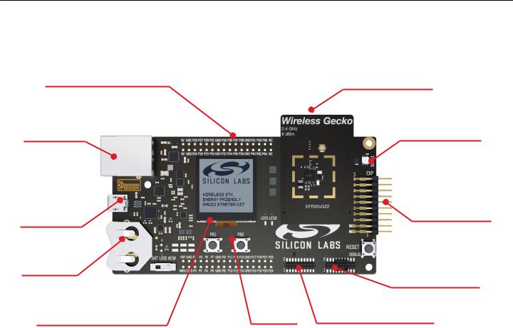
2.1 Hardware Layout
The layout of the EFR32xG22 2.4 GHz 6 dBm QFN32 Wireless Starter Kit is shown in the figure below.
Radio Board Breakout Pads
On-board USB and
Ethernet J-Link
Debugger
USB-serial-port
Packet-trace
Advanced Energy
Monitoring
Battery or
USB power
Ultra-low power 128x128 |
|
pixel memory LCD |
Buttons |
(Not connected to BRD4183A) |
and LEDs |
Plug-in Radio Board
Si7021 Humidity and
Temperature Sensor
(Not connected to BRD4183A)
EXP-header for expansion boards
ARM Coresight 19-pin trace/debug header
Serial-port, packet trace and Advanced Energy Monitoring header
Figure 2.1. Kit Hardware Layout
silabs.com | Building a more connected world. |
Rev. 1.0 | 5 |
|
|
UG431: EFR32xG22 2.4 GHz 6 dBm QFN32 Wireless Starter Kit User's Guide
Hardware Overview
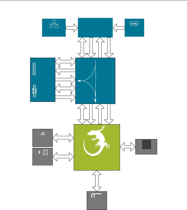
2.2 Block Diagram
An overview of the EFR32xG22 2.4 GHz 6 dBm QFN32 Wireless Starter Kit is shown in the figure below.
|
|
|
Board |
|
|
|
|
|
|
|
|
|
USB Mini-B |
||
RJ-45 Ethernet |
|
|
Controller |
|
|
||
Connector |
|
|
|
|
|
|
Connector |
|
|
|
|
|
|
|
|
|
|
|
|
|
|
|
|
|
|
UART |
AEM |
Packet Trace |
Debug |
||
UART
Simplicity
Connector AEM
Packet Trace
Debug Debug
Connector
ETM Trace
OUT
IN
Multiplexer
MCU
UART |
AEM |
Packet Trace |
Debug |
GPIO
EXP
Header 8 Mbit
SPI MX25R
Serial Flash
User Button & |
GPIO |
EFR32xG22 |
|
||
|
|
|
User LED |
|
Wireless SoC |
|
|
|
|
|
2.4 GHz RF
Inverted-F SMA
PCB AntennaConnector
Figure 2.2. Kit Block Diagram
silabs.com | Building a more connected world. |
Rev. 1.0 | 6 |
|
|

UG431: EFR32xG22 2.4 GHz 6 dBm QFN32 Wireless Starter Kit User's Guide
Connectors
3. Connectors
This chapter gives you an overview of the Wireless STK Mainboard connectivity. The placement of the connectors are shown in the figure below.
|
GND |
|
|
|
|
|
P25P27P29P31P33P35P37P39P41P43P45 |
NC |
|
|
|
|
GND |
|
GND |
|
|
|
P24P26P28P30P32P34P36P38P40P42P44 |
NC |
|
|
|
|
5V |
|
GND |
3V3 |
|
5V |
|
|
3V3 |
Radio |
|
|
|
|
|
|
Connectors |
Ethernet |
|
|
|
|
Board |
|
|
|
|
|
|
Connector |
|
|
|
|
|
|
|
|
|
|
EXP |
J-Link USB |
|
|
|
|
Header |
Connector |
|
|
|
|
|
|
|
|
Debug |
|
|
|
|
Simplicity |
Connector |
|
|
|
|
|
|
|
|
|
|
Connector |
|
|
|
VMCU |
|
|
VRF |
|
|
VMCU |
GNDP1 P3 |
|
|
|
|
|
P5 P7 P9 P11P13 P15 P17 P19 P21P23 GNDVRF |
|
|||
|
GNDP0 P2 P4 P6 P8 P10P12 P14 P16 P18 P20P22 GND |
|
|
||
Figure 3.1. Mainboard Connector Layout
3.1 J-Link USB Connector
The J-Link USB connector is situated on the left side of the Wireless Starter Kit Mainboard. Most of the kit's development features are supported through this USB interface when connected to a host computer, including:
•Debugging and programming of the target device using the on-board J-Link debugger
•Communication with the target device over the virtual COM port using USB-CDC
•Accurate current profiling using the AEM
In addition to providing access to development features of the kit, this USB connector is also the main power source for the kit. USB 5V from this connector powers the board controller and the AEM. It is recommended that the USB host be able to supply at least 500 mA to this connector, although the actual current required will vary depending on the application.
3.2 Ethernet Connector
The Ethernet connector provides access to all of the Wireless Starter Kit's development features over TCP/IP. The Ethernet interface provides some additional development features to the user. Supported features include:
•Debugging and programming of the target device using the on-board J-Link debugger
•Communication with the target device over the virtual COM port using TCP/IP socket 4901
•"VUART" communication with the target device over the debug SWD/SWO interface using TCP/IP socket 4900
•Accurate current profiling using the AEM
•Real-time radio packet and network analysis using the Packet Trace Interface
•Access to advanced configuration options using the admin console over TCP/IP socket 4902
Note: The Wireless Starter Kit cannot be powered using the Ethernet connector, so in order to use this interface, the USB connector must be used to provide power to the board.
silabs.com | Building a more connected world. |
Rev. 1.0 | 7 |
|
|

UG431: EFR32xG22 2.4 GHz 6 dBm QFN32 Wireless Starter Kit User's Guide
Connectors
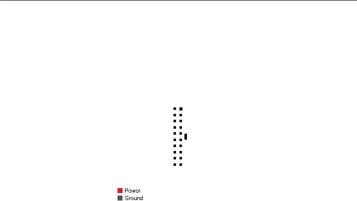
3.3 Breakout Pads
Most pins of the EFR32 are routed from the radio board to breakout pads at the top and bottom edges of the Wireless STK Mainboard. A 2.54 mm pitch pin header can be soldered on for easy access to the pins. The figure below shows you how the pins of the EFR32 map to the pin numbers printed on the breakout pads. To see the available functions on each, refer to the data sheet for EFR32MG22C224F512IM32.
J101
VMCU 
 VMCU
VMCU
GND 
 GND
GND
NC / P0 
 P1 / NC
NC / P2 
 P3 / NC
UIF_BUTTON0 / EXP7 / PB00 / P4 
 P5 / NC
UIF_LED0 / EXP9 / PB01 / P6 
 P7 / NC
NC / P8 
 P9 / PA05 / EXP12 / VCOM_TX
NC / P10 
 P11 / PA06 / EXP14 / VCOM_RX
NC / P12 
 P13 / NC
VCOM_RTS / PA00 / P14 
 P15 / NC
DBG_TCK_SWCLK / PA01 / P16 
 P17 / NC
DBG_TMS_SWDIO / PA02 / P18 
 P19 / NC
DBG_TDO_SWO / PA03 / P20 
 P21 / PB02 / VCOM_CTS
VCOM_ENABLE / PA04 / P22 
 P23 / NC
GND 
 GND
GND
VRF 
 VRF
VRF
J102
5V 
 5V GND
 GND
GND
NC / P24 
 P25 / PC04 / PTI_DATA NC / P26
 P27 / PC05 / PTI_SYNC NC / P28
 P29 / NC
NC / P30 
 P31 / NC
NC / P32 
 P33 / NC
NC / P34 
 P35 / NC
NC / P36 
 P37 / NC
NC / P38 
 P39 / NC
NC / P40 
 P41 / NC
NC / P42 
 P43 / NC
NC / P44 
 P45 / NC
NC 
 NC
NC
GND 
 GND 3V3
 3V3
3V3
Figure 3.2. Breakout Pad Pin Mapping
silabs.com | Building a more connected world. |
Rev. 1.0 | 8 |
|
|
UG431: EFR32xG22 2.4 GHz 6 dBm QFN32 Wireless Starter Kit User's Guide
Connectors
3.4 EXP Header
The EXP header is an angled 20-pin expansion header provided to allow connection of peripherals or plugin boards to the kit. It is located on the right-hand side of the mainboard, and it contains a number of I/O pins that can be used with most of the EFR32 Wireless Gecko's features. Additionally, the VMCU, 3V3, and 5V power rails are also exported.
The connector normally follows a standard which ensures that commonly used peripherals, such as an SPI, a UART, and an I2C bus, are available on fixed locations in the connector. The rest of the pins are used for general purpose IO. This allows the definition of expansion boards (EXP boards) that can plug into a number of different Silicon Labs Starter Kits. However, due to limitations in the number of available I/O pins on the EFR32xG22, the connector on this kit has a reduced feature set.
The figure below shows the pin assignment of the EXP header. Because of limitations in the number of available GPIO pins, some of the EXP header pins are not connected and the rest are shared with kit features.
3V3 |
20 |
|
|
|
|
|
|
|
|
|
|
19 |
BOARD_ID_SDA |
5V |
18 |
|
|
|
|
|
|
|
|
|
|
17 |
BOARD_ID_SCL |
NC |
16 |
|
|
|
|
|
|
|
|
|
|
15 |
NC |
UART_RX / PA06 |
14 |
|
|
|
|
|
|
|
|
|
|
13 |
NC |
UART_TX / PA05 |
12 |
|
|
|
|
|
|
|
|
|
|
11 |
NC |
NC |
10 |
|
|
|
|
|
|
|
|
|
|
9 |
PB01 / GPIO |
NC |
8 |
|
|
|
|
|
|
|
|
|
|
7 |
PB00 / GPIO |
NC |
6 |
|
|
|
|
|
|
|
|
|
|
5 |
NC |
NC |
4 |
|
|
|
|
|
|
|
|
|
|
3 |
NC |
VMCU |
2 |
|
|
|
|
|
|
|
|
|
|
1 |
GND |
|
|
|
|
|
|
|
|
|
|
|
|
|
|
 EFR32 I/O Pin
 Reserved (Board Identification)
Figure 3.3. EXP Header
silabs.com | Building a more connected world. |
Rev. 1.0 | 9 |
|
|

UG431: EFR32xG22 2.4 GHz 6 dBm QFN32 Wireless Starter Kit User's Guide
Connectors
3.4.1 EXP Header Pinout
The pin-routing on the EFR32 is very flexible, so most peripherals can be routed to any pin. However, many pins are shared between the EXP header and other functions on the Wireless STK Mainboard. The table below includes an overview of the mainboard features that share pins with the EXP header.
Table 3.1. EXP Header Pinout
Pin |
Connection |
EXP Header Function |
Shared Feature |
Peripheral Mapping |
|
|
|
|
|
20 |
3V3 |
Board controller supply |
|
|
|
|
|
|
|
18 |
5V |
Board USB voltage |
|
|
|
|
|
|
|
16 |
NC |
I2C_SDA |
|
|
|
|
|
|
|
14 |
PA06 |
UART_RX |
VCOM_RX |
USART1_RX |
|
|
|
|
|
12 |
PA05 |
UART_TX |
VCOM_TX |
USART1_TX |
|
|
|
|
|
10 |
NC |
SPI_CS |
|
|
|
|
|
|
|
8 |
NC |
SPI_SCLK |
|
|
|
|
|
|
|
6 |
NC |
SPI_MISO |
|
|
|
|
|
|
|
4 |
NC |
SPI_MOSI |
|
|
|
|
|
|
|
2 |
VMCU |
EFR32 voltage domain, included in AEM measurements. |
|
|
|
|
|
|
|
|
|
|
||
19 |
BOARD_ID_SDA |
Connected to board controller for identification of add-on boards. |
||
|
|
|
||
17 |
BOARD_ID_SCL |
Connected to board controller for identification of add-on boards. |
||
|
|
|
|
|
15 |
NC |
I2C_SCL |
|
|
|
|
|
|
|
13 |
NC |
GPIO |
|
|
|
|
|
|
|
11 |
NC |
GPIO |
|
|
|
|
|
|
|
9 |
PB01 |
GPIO |
UIF_LED0 |
|
|
|
|
|
|
7 |
PB00 |
GPIO |
UIF_BUTTON0 |
|
|
|
|
|
|
5 |
NC |
GPIO |
|
|
|
|
|
|
|
3 |
NC |
GPIO |
|
|
|
|
|
|
|
1 |
GND |
Ground |
|
|
|
|
|
|
|
silabs.com | Building a more connected world. |
Rev. 1.0 | 10 |
|
|
Loading...