


silabs.com | Building a more connected world. 1 | Page
AN1305: RS9116N Regulatory Test Application Note
Version 1.1
10/21/2020

AN1305: RS9116N Regulatory Test Application Note
Version 1.1
silabs.com | Building a more connected world. 2 | Page
Table of Contents
1 Overview ....................................................................................................................................................................... 6
2 Hardware (EVB) Details................................................................................................................................................ 7
3 Software Details ........................................................................................................................................................... 9
3.1 Compilation Procedure ........................................................................................................................................... 9
4 GUI Usage ................................................................................................................................................................... 12
4.1 PER TEST Home ................................................................................................................................................. 12
4.2 WLAN TEST ......................................................................................................................................................... 13
4.2.1 WLAN_TX_PER ......................................................................................................................................... 13
4.2.1.1 Tx Start ......................................................................................................................................... 18
4.2.1.2 Tx Stop ................................................................................................................................ ......... 18
4.2.2 WLAN_RX_PER ......................................................................................................................................... 18
4.2.2.1 Rx Start ........................................................................................................................................ 19
4.2.2.2 Rx Stop ........................................................................................................................................ 19
4.3 BT TEST .............................................................................................................................................................. 19
4.3.1 BT_TX_PER ............................................................................................................................................... 19
4.3.1.1 Tx Start ......................................................................................................................................... 20
4.3.1.2 Tx Stop ................................................................................................................................ ......... 20
4.3.2 BT_RX_PER ............................................................................................................................................... 20
4.3.2.1 Rx Start ........................................................................................................................................ 21
4.3.2.2 Rx Stop ........................................................................................................................................ 21
4.4 BLE TEST ............................................................................................................................................................ 21
4.4.1 BLE_TX_PER ............................................................................................................................................. 22
4.4.1.1 Tx Start ......................................................................................................................................... 23
4.4.1.2 Tx Stop ................................................................................................................................ ......... 23
4.4.2 BLE_RX_PER............................................................................................................................................. 23
4.4.2.1 Rx Start ........................................................................................................................................ 24
4.4.2.2 Rx Stop ........................................................................................................................................ 24
5 Appendix A: SDIO Header Pin Description .............................................................................................................. 25
6 Revision History ................................................................................................ ................................ ......................... 26

AN1305: RS9116N Regulatory Test Application Note
Version 1.1
silabs.com | Building a more connected world. 3 | Page
Table of Figures
Figure 1: RS9116 EVB.......................................................................................................................................................... 7
Figure 2: Menuconfig .......................................................................................................................................................... 10
Figure 3: Interface Selection ............................................................................................................................................... 10
Figure 4: Save Config ......................................................................................................................................................... 11
Figure 5: PER_Test Home Page ........................................................................................................................................ 12
Figure 6: WLAN_TX_PER_TEST Page .............................................................................................................................. 13
Figure 7: WLAN Channel List ............................................................................................................................................. 17
Figure 8: WLAN_RECEIVE_TEST Page ............................................................................................................................ 18
Figure 9: BT_TX_PER_TEST Page .................................................................................................................................... 19
Figure 10: BT_RECEIVE_TEST Page ................................................................................................................................ 21
Figure 11: BLE_TX_PER_TEST Page................................................................................................................................ 22
Figure 12: BLE_RECEIVE_TEST Page .............................................................................................................................. 23
Figure 13: SDIO Header PIN Orientation ............................................................................................................................ 25

AN1305: RS9116N Regulatory Test Application Note
Version 1.1
silabs.com | Building a more connected world. 4 | Page
Acronyms
PER: Packet Error Rate
WLAN: Wireless Local Area Network
BT: Bluetooth Classic
BLE: Bluetooth Low Energy
EVB: Evaluation Board
Tx: Transmit
Rx: Receive
GUI: Graphical User Interface

AN1305: RS9116N Regulatory Test Application Note
Version 1.1
silabs.com | Building a more connected world. 5 | Page
About this Document
This document describes the guidelines for using the GUI Interface for PER testing of RS9116 Products in n-Link mode.

AN1305: RS9116N Regulatory Test Application Note
Version 1.1
silabs.com | Building a more connected world. 6 | Page
1 Overview
The RS9116 software provides application to test transmit and Receive Performance of RS9116 Module in PER test
mode. The GUI interface eases the effort for the user in evaluating the product.
AN1305: RS9116N Regulatory Test Application Note
Version 1.1
silabs.com | Building a more connected world. 7 | Page
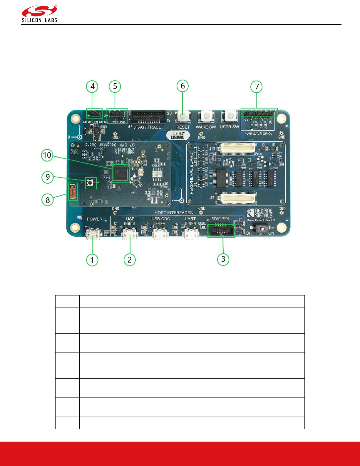
2 Hardware (EVB) Details
This section describes various components and connection headers of RS9116 EVB. n-Link® (Hosted) solutions support
SDIO and USB interfaces only. The same EVB can also be used for WiSeConnect® (Embedded) solutions, where we
support UART, SPI, USB and USB-CDC interfaces.
Figure 1: RS9116 EVB
Option
Feature name
Description
1
Power USB
It is used to supply power to the EVB. While using USB
interface, connecting power USB is optional as power
drawn from USB itself.
2
USB
It is the port for USB interface used to communicate with
host.
3
SDIO/SPI
It is the common port for both SDIO and SPI interface,
used to communicate with host. Note: In nLink only SDIO
is supported.
4
Measurement
It is a provision to measure current consumption of chip
using ammeter or Digital Multi meter.
5
3.3V/1.8V Voltage
selection
It is a provision to select the operating voltage of chip. User
need to set this to either 3.3V or 1.8V selection.
6
Reset Switch
Provision to reset chip
AN1305: RS9116N Regulatory Test Application Note
Version 1.1
silabs.com | Building a more connected world. 8 | Page
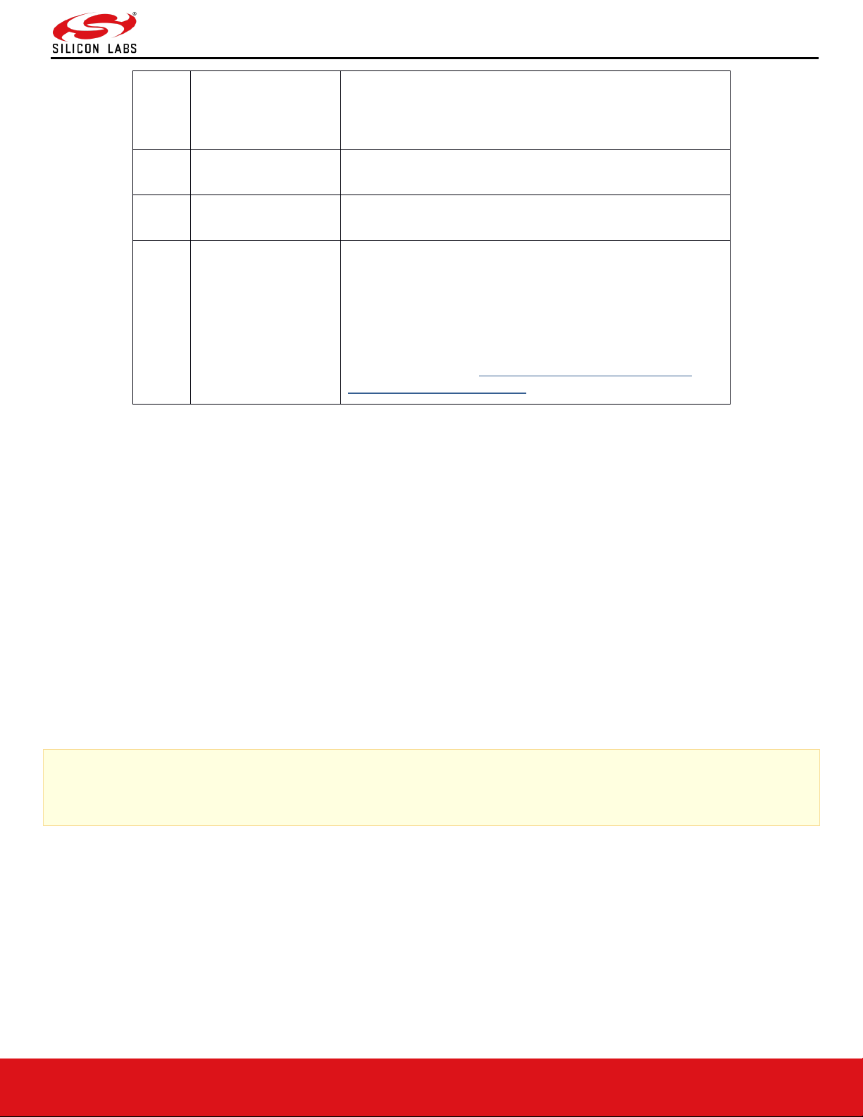
7
Power save GPIO’s
These are GPIO’s which need to be connected
appropriately to the host, while using GPIO handshake
in ULP or WOWLAN. Please refer TRM for more
details.
8
Onboard antenna
/Internal Antenna
This is an onboard antenna used for wireless
communications
9
External Antenna
UFL connector
Provision given to connect external antenna as per the
requirement.
10
RS9116 SOC
Chip number will be printed on top of SOC which has
below information included in it.
M/N:M7DB6
RS9116-CC0-2
FCC ID:KFS-M7DBN6
For details, refer to https://www.silabs.com/wireless/wi-
fi/rs9116-wi-fi-transceiver-socs
Power Supply and Interface Connectivity:
The board is designed to configure the module to use the interface on which power supply is detected. This is indicated
through the LEDs mounted on the board. The SDIO interface requires power supply to be provided over the USB
connector. Hence, for SDIO interface, it is required that the power USB be connected first (i.e power up first) followed by
the SDIO or SPI connection.
Follow the below steps to use the EVB with possible host interface options:
1. USB: Connect the Micro A/B-type USB cable between a USB port of a PC/Laptop and the micro-USB port
labeled USB on the EVB.
2. SDIO Mode: (For SDIO Header Pin Description, please refer to Appendix A. Appendix A: SDIO Header Pin Description.)
Current Measurement:
There is a 2-pin inline jumper available for measuring the current being sourced by the module during different stages of
operation. This is labeled as "MEASUREMENT" on the baseboard. The user may connect a power meter or an ammeter
to this jumper to measure the current.
Note:
Make sure the ISP switch is in OFF state. If it is ON state you will not get the boot loader messages

AN1305: RS9116N Regulatory Test Application Note
Version 1.1
silabs.com | Building a more connected world. 9 | Page
3 Software Details
Driver: https://www.silabs.com/wireless/wi-fi/rs9116-wi-fi-transceiver-modules
RS9116.NB0.NL.GENR.LNX
The driver software is delivered as a tarball with a filename in the format: RS9116.NXX.NL.GENR.LNX.x.y.z.zip
Where the naming convention is as follows:
NXX – defines whether the package supports only Wi-Fi (N00) or Bluetooth Classic/Low Energy along with Wi-Fi(NB0).
x.y.z – identifies the software release package version.
The software package contains the following files/folders:
• Readme.txt
• Releasenotes.txt
• Documents
• Binary_files (optional)
• source (optional)
Either of the Binary files or source folders might be empty depending on the request we have sent to Silicon Labs and
whether we have signed into a Software License Agreement for the source code.
If the source code has been provided, follow the instructions given below to compile.
3.1 Compilation Procedure
Go to source code path
# cd RS9116.NXX.NL.GENR.LNX.x.y.z/source/host
Following are the options available in menuconfig of the driver:
• USB Interface support
• SDIO Interface support
• Operating system: Linux or Android
• Nl80211 support
• HOSTAPD Support
• WIFI
• BLUETOOTH
• ZIGBEE (ZigBee is not supported in current release)
1. To open menuconfig utility, untar the release package, go to source → host folder and enter the given command
below
# make menuconfig
2. Below images explains usage of menuconfig utility. User has to select the required Protocol (Wi-Fi/BT) as per the
User's end application.

AN1305: RS9116N Regulatory Test Application Note
Version 1.1
silabs.com | Building a more connected world. 10 | Page
Figure 2: Menuconfig
3. Selecting the support for NL80211 as following
Figure 3: Interface Selection
4. After selecting the configuration, exit the menuconfig and save the configuration. Please refer below image of
saving the configuration

AN1305: RS9116N Regulatory Test Application Note
Version 1.1
silabs.com | Building a more connected world. 11 | Page
Figure 4: Save Config
5. By default the configuration is enabled with Wi-Fi only. If user wants to compile the driver for a particular protocol,
he can enable or disable the desired protocols using menuconfig utility.
6. Now compile the driver using the command below
# make clean compile_driver onebox_utils
7. Upon successful compilation, you will see a print on the console "Compilation Done Successfully"

AN1305: RS9116N Regulatory Test Application Note
Version 1.1
silabs.com | Building a more connected world. 12 | Page
4 GUI Usage
1. Install tkinter package for Python using the below command
⚫ Ubuntu:
# sudo apt-get install python-tk
⚫ Fedora: yum install tkinter
# sudo yum install tkinter
2. Please navigate to the “release” directory in given package.
Open the common_insert.sh file in the “release” directory using an editor like vim.
Ensure the below parameters are set as specified:
DRIVER_MODE=2
POWER_SAVE_OPTION=0
STANDBY_ASSOC_CHAIN_SEL=0
LMAC_BEACON_DROP=0
3. To Start the GUI please enter the following command
# python PER_TEST_GUI.py
4.1 PER TEST Home
The figure below shows the home page for the PER Tests
Figure 5: PER_Test Home Page

AN1305: RS9116N Regulatory Test Application Note
Version 1.1
silabs.com | Building a more connected world. 13 | Page
In the PER_TEST page we can select following options
1. Choose Module type: Select type of sample connected via USB port to Linux PC
a) Q7
b) M15SB
c) M7DB
2. Choose Protocol: Select the protocol to test
a) wlan:IEEE 802.11a/b/g/n
b) bt: BT Core v2.1+EDR
c) ble: BLE/BLR Core v5.0
3. Choose Antenna: Select antenna to which output from chip should be redirected
a) PCB_ANTENNA: Enables onboard PCB antenna
b) EXTERNAL_ANTENNA: Enables u.FL port to connect external antenna or Instruments
4. Vbatt_supply: Select the sample operating voltage
a) 3p3
b) 1p8
5. Receive: Select the mode of test
a) Disable: Transmit test
b) Enable: Receive test
After selecting the intended options click update and wait till driver is loaded and redirects to specific test case page
based on selected options.
4.2 WLAN TEST
If the protocol selected in PER_TEST page is <wlan>, the application redirects to WLAN Transmit or Receive page
based on the <Receive> option selected in PER_TEST page
4.2.1 WLAN_TX_PER
The figure below shows the WLAN Transmit Test page
Figure 6: WLAN_TX_PER_TEST Page

AN1305: RS9116N Regulatory Test Application Note
Version 1.1
silabs.com | Building a more connected world. 14 | Page
In the WLAN_TX_PER_TEST page we can select following options
1. Choose Region: Select region of operation
a) World_wide
b) FCC(US)
c) ETSI(Europe)
d) JP(japan)
2. Choose channel: Select the Band for the list of channels available as specified by IEEE 802.11 standard.
The following table maps the channel numbers to the center frequencies for 20MHz and 40MHz bandwidth modes in 2.4
GHz and 5 GHz bands.

AN1305: RS9116N Regulatory Test Application Note
Version 1.1
silabs.com | Building a more connected world. 15 | Page
Band
(GHz)
Bandwidth
(MHz)
Channel
Number
Center
Frequency (MHz)
2.4
20 1 2412
2.4
20 2 2417
2.4
20 3 2422
2.4
20 4 2427
2.4
20 5 2432
2.4
20 6 2437
2.4
20 7 2442
2.4
20 8 2447
2.4
20 9 2452
2.4
20
10
2457
2.4
20
11
2462
2.4
20
12
2467
2.4
20
13
2472
2.4
40 3 2422
2.4
40 4 2427
2.4
40 5 2432
2.4
40 6 2437
2.4
40 7 2442
2.4
40 8 2447
2.4
40 9 2452
2.4
40
10
2457
2.4
40
11
2462
4.9
20
184
4920
4.9
20
188
4940
4.9
20
192
4960
4.9
20
196
4980
5
20 8 5040
5
20
12
5060
5
20
16
5080
5
20
36
5180

AN1305: RS9116N Regulatory Test Application Note
Version 1.1
silabs.com | Building a more connected world. 16 | Page
5
20
40
5200
5
20
44
5220
5
20
48
5240
5
20
52
5260
5
20
56
5280
5
20
60
5300
5
20
64
5320
5
20
100
5500
5
20
104
5520
5
20
108
5540
5
20
112
5560
5
20
116
5580
5
20
120
5600
5
20
124
5620
5
20
128
5640
5
20
132
5660
5
20
136
5680
5
20
140
5700
5
20
149
5745
5
20
153
5765
5
20
157
5785
5
20
161
5805
5
20
165
5825
5
40
38
5190
5
40
42
5210
5
40
46
5230
5
40
50
5250
5
40
54
5270
5
40
58
5290
5
40
62
5310
5
40
102
5510

AN1305: RS9116N Regulatory Test Application Note
Version 1.1
silabs.com | Building a more connected world. 17 | Page
5
40
106
5530
5
40
110
5550
5
40
114
5570
5
40
118
5590
5
40
122
5610
5
40
126
5630
5
40
130
5650
5
40
134
5670
5
40
138
5690
5
40
151
5755
5
40
155
5775
5
40
159
5795
5
40
163
5815
Figure 7: WLAN Channel List

AN1305: RS9116N Regulatory Test Application Note
Version 1.1
silabs.com | Building a more connected world. 18 | Page
3. Choose Rate: Select transmission data rate
a) 1,2,5.5,11: IEEE 802.11b Rates
b) 6,9,12,18,24,36,48,54: IEEE 802.11a/g Rates
c) mcs0-mcs7: IEEE 802.11n Rates
4. Choose bandwidth: Select transmission bandwidth
a) 20MHz
b) 40MHz
5. Choose Mode: Select mode of transmission
a) Continuous: Transmits in a continuous manner
b) Burst: Transmits in bursts
6. Choose transmit power: Select the Tx Output Power in dBm
a) 0-22: Tx Output Power in dBm
b) 127: Default(Max Possible) Tx Output Power
7. Choose packet length: Length of the packet to be transmitted in bytes
a) For 802.11b & 802.11a/g Rates, Maximum allowed length is 1536 bytes
b) For 802.11n Rates, Maximum allowed length is 4096 bytes
4.2.1.1 Tx Start
Once the Transmit settings are configured as above, click on “Transmit_start”, to start the WLAN transmission.
4.2.1.2 Tx Stop
Click on “Transmit_stop” to stop the WLAN transmission.
Note: This has to be done before Tx Start is initiated again
4.2.2 WLAN_RX_PER
The figure below shows the WLAN Receive Test page
Figure 8: WLAN_RECEIVE_TEST Page
In the WLAN_RECEIVE_TEST page we can select following options:
1. Choose Protocol: Select the Band for the list of channels available as specified by IEEE 802.11 standard.

AN1305: RS9116N Regulatory Test Application Note
Version 1.1
silabs.com | Building a more connected world. 19 | Page
a) WLAN_2G: WLAN - 2.4GHz Band. Channels available are 1-14
b) WLAN_5G: WLAN - 5GHz Band. Channels available are 36-165
2. Choose bandwidth: Select transmission bandwidth
a) 20MHz
b) 40MHz
3. RF Chain: Select receive chain.
a) HP: Uses HP Chain for reception
b) LP: Used LP Chain for reception
4.2.2.1 Rx Start
Once the Receive settings are configured as above, click on “Receive_start” to start the WLAN reception.
4.2.2.2 Rx Stop
Click on “Receive_stop” to stop the WLAN reception.
Note: This has to be done before Rx Start is initiated again
4.3 BT TEST
If the protocol selected in PER_TEST page is <bt>, the application redirects to BT Transmit or Receive page based
on the <Receive> option selected in PER_TEST page
4.3.1 BT_TX_PER
The figure below shows the BT Transmit Test page
Figure 9: BT_TX_PER_TEST Page
In the BT_TX_PER_TEST page we can select following options
1. Choose channel: Select the Channel Index for the BT transmission as per Bluetooth Core v2.1+EDR Standard

AN1305: RS9116N Regulatory Test Application Note
Version 1.1
silabs.com | Building a more connected world. 20 | Page
a) Channels available are 0-78
2. Choose Packet type: Select the type of packet for the transmission as per Bluetooth Core v2.1+EDR Standard
3. Choose Mode: Select mode of transmission
a) Continuous: Transmits in a continuous manner
b) Burst: Transmits in bursts
4. Choose transmit power: Select the Tx Output Power in dBm
a) 0-22: Tx Output Power in dBm for HP RF Chain
b) 127: Default Tx Output Power for HP RF Chain
c) 31: Default Tx Output Power for LP RF Chain
5. Choose Hopping: Select the Mode of frequency hopping
a) Disable: Disables hopping across frequencies
b) Enable: Enables hopping across fixed frequencies
c) AFH_Enable: Enables hopping across frequencies provided
6. BT Address: Provide the 48-bit Bluetooth Address in hexadecimal format
7. Choose Payload type: Select type of the payload to be transmitted
a) 0x00:
b) 0xFF:
c) 0xF0: Used for measuring Modulation Characteristics (Delta F1 Average)
d) 0x55: Used for measuring Modulation Characteristics (Delta F1 Max, Delta F2 Average, Drift characteristics)
e) PN9: Used for measuring EVM, Output Power, etc
8. Choose RF Chain: Select the RF Chain to be used for the transmission
a) HP: Uses HP Chain for the transmission
b) LP: Uses LP Chain for the transmission
4.3.1.1 Tx Start
Once the Transmit settings are configured as above, click on “BT Transmit_start” to start the BT transmission.
4.3.1.2 Tx Stop
Click on “BT Transmit_stop” to stop the BT transmission.
Note: This has to be done before Tx Start is initiated again
4.3.2 BT_RX_PER
The figure below shows the BT Receive Test page:

AN1305: RS9116N Regulatory Test Application Note
Version 1.1
silabs.com | Building a more connected world. 21 | Page
Figure 10: BT_RECEIVE_TEST Page
In the BT_RECEIVE_TEST page we can select following options
1. Choose protocol: Select the protocol as BT for the list of channels available as specified by Bluetooth standard
a) BT: Bluetooth v2.1+EDR. Channels available are 0-78
2. Choose Rate: Select the rate of the packet to be received
a) 1MBPS: Basic Data Rate
b) 2MBPS/3MBPS: Enhanced Data Rate
3. BT Address: Provide the 48-bit Bluetooth Address in hexadecimal format
4. No of Packets: Indicates the number of expected packets per second
Note: This is needed to provide the accurate PER in the Statistics
5. Choose RF Chain: Select receive chain.
a) HP: Uses HP Chain for reception
b) LP: Uses LP Chain for reception
4.3.2.1 Rx Start
Once the Receive settings are configured as above, click on “Receive_start” to start the BT reception.
4.3.2.2 Rx Stop
Click on “Receive_stop” to stop the BT reception.
Note: This has to be done before Rx Start is initiated again.
4.4 BLE TEST
If the protocol selected in PER_TEST page is <ble>, the application redirects to BLE Transmit or Receive page
based on the <Receive> option selected in PER_TEST page

AN1305: RS9116N Regulatory Test Application Note
Version 1.1
silabs.com | Building a more connected world. 22 | Page
4.4.1 BLE_TX_PER
The figure below shows the BLE Transmit Test page
Figure 11: BLE_TX_PER_TEST Page
In the BLE_TX_PER_TEST page we can select following options
1. Choose channel: Select the Channel Index for the LE transmission as per Bluetooth Core v5.0 Standard
a) Channels available are 0-39
2. Choose Rate: Select the rate of packet for the transmission as per Bluetooth Core v5.0 Standard
a) 1M: Enables transmission of BLE-1Mbps
b) 2M: Enables transmission of BLE-2Mbps
c) 125K: Enables transmission of BLR-125Kbps
d) 500K: Enables transmission of BLR-500Kbps
3. Choose Mode: Select mode of transmission
a) Continuous: Transmits in a continuous manner
b) Burst: Transmits in bursts
4. Choose transmit power: Select the Tx Output Power in dBm
a) 0-22: Tx Output Power in dBm for HP RF Chain
b) 127: Default Tx Output Power for HP RF Chain
c) 31: Default Tx Output Power for LP RF Chain
5. Choose Hopping: Select the Mode of frequency hopping
a) Disable: Disables hopping across frequencies
b) Enable: Enables hopping across fixed frequencies
c) AFH_Enable: Enables hopping across frequencies provided
6. Access Code: Provide the 32-bit Access Code in hexadecimal format.
Note: The standard Access Code for LE Reference packet is “71764129”.
This is used in Direct Test Mode of Bluetooth 5.0 Standard.
7. Choose Payload type: Select type of the payload to be transmitted
a) 0x00:
b) 0xFF:
c) 0xF0: Used for measuring Modulation Characteristics (Delta F1 Average)
d) 0x55: Used for measuring Modulation Characteristics (Delta F1 Max, Delta F2 Average, Drift characteristics)
e) PN9: Used for measuring EVM, Output Power, etc
8. Choose RF Chain: Select the RF Chain to be used for the transmission

AN1305: RS9116N Regulatory Test Application Note
Version 1.1
silabs.com | Building a more connected world. 23 | Page
a) HP: Uses HP Chain for the transmission
b) LP: Uses LP Chain for the transmission
4.4.1.1 Tx Start
Once the Transmit settings are configured as above, click on “BLE Transmit_start” to start the BLE transmission.
4.4.1.2 Tx Stop
Click on “BLE Transmit_stop” to stop the BLE transmission.
Note: This has to be done before Tx Start is initiated again
4.4.2 BLE_RX_PER
Then figure below shows the BLE Receive Test page
Figure 12: BLE_RECEIVE_TEST Page
In the BLE_RECEIVE_TEST page we can select following options
1. Choose protocol: Select the protocol as BT for the list of channels available as specified by Bluetooth standard
a) BLE: Bluetooth v5.0. Channels available are 0-39
2. Choose Rate: Select the rate of the packet to be received
a) 1MBPS: LE-1Mbps
b) 2MBPS: LE-2Mbps
c) 125_500_KBPS: LR
3. Access Code: Provide the 32-bit Access Code in hexadecimal format
Note: The standard Access Code for LE Reference packet is “71764129”. This is used in Direct Test Mode of
Bluetooth 5.0 Standard.
4. No of Packets: Indicates the number of expected packets per second
Note: This is needed to provide the accurate PER in the Statistics
5. Choose RF Chain: Select receive chain.

AN1305: RS9116N Regulatory Test Application Note
Version 1.1
silabs.com | Building a more connected world. 24 | Page
a) HP: Uses HP Chain for reception
b) LP: Uses LP Chain for reception
4.4.2.1 Rx Start
Once the Receive settings are configured as above, click on “Receive_start” to start the BLE reception.
4.4.2.2 Rx Stop
Click on “Receive_stop” to stop the BLE reception.
Note: This has to be done before Rx Start is initiated again

AN1305: RS9116N Regulatory Test Application Note
Version 1.1
silabs.com | Building a more connected world. 25 | Page
5 Appendix A: SDIO Header Pin Description
The following figure describes the pins of SDIO header.
Figure 13: SDIO Header PIN Orientation
SDIO Header Pin Description
The following table describes the pins of SDIO header.
Table 1: SDIO Header Pins
Pin No.
Pin Name
Direction
Description
1
SDIO_DATA3
Input/Output
Data3 of SDIO interface.
2
SDIO_CMD
Input/Output
SDIO Mode: SDIO interface command signal.
3
GND
-
Ground
4
VDD
-
Supply voltage.
5
SDIO_CLK
Input
This signal is SDIO clock.
6
GND
-
Ground
7
SDIO_DATA0
Input/Output
Data0 of SDIO interface.
8
SDIO_DATA1
Input/Output
Data1 of SDIO interface.
9
SDIO_DATA2
Input/Output
Data2 of SDIO interface.
10
NC - No Connect
Reset - When the EVB is powered through the USB on "Power" port or through the power on any interface (UART, USB,
USB-CDC, SDIO/SPI) than it gets the Power on Reset.
To control the reset there are two methods:
1. Reset Button on baseboard.
2. Host can control the Reset by controlling the pin #2 (RST_PS) on header J9 via GPIO.
Note: Signal Integrity Guidelines for SPI/SDIO interface: Glitches in the SPI/SDIO clock can potentially take the SPI/SDIO
interface out of synchronization. The quality and integrity of the clock line needs to be maintained. In case a cable is used
for board to board connection, the following steps are recommended (please note that this is not an exhaustive list of
guidelines and depending on individual cases additional steps may be needed.):
1. Minimize the length of the SPI/SDIO bus cable to as small as possible, preferably to within an inch or two.
2. Increase the number of ground connections between the EVB and the Host processor PCB.

AN1305: RS9116N Regulatory Test Application Note
Version 1.1
silabs.com | Building a more connected world. 26 | Page
6 Revision History
Revision No.
Version No.
Date
Changes
1
1.0
Nov 2019
Initial Version
2
1.1
May 2020
Updated with improvements

AN1305: RS9116N Regulatory Test Application Note
Version 1.1
silabs.com | Building a more connected world. 27 | Page
 Loading...