

Page 1

RS9113 WiSeConnectTM
BBlluueettooootthh CCllaassssiicc SSooffttwwaarree PPrrooggrraammmmiinngg RReeffeerreennccee
MMaannuuaall
VVeerrssiioonn 11..77..99
MMaayy 22002200
silabs.com | Building a more connected world.
Page 2

RRSS99111133--WWiiSSeeCCoonnnneecct
t
TTM
M
BBlluueettooootthh CCllaassssiicc SSooffttwwaarree PPrrooggrraammmmiinngg RReeffeerreennccee
MMaannuuaall
VVeerrssiioonn 11..77..99
About this Document
This document describes the commands to operate the RS9113-WiSeConnect Module Family for
Bluetooth. Bluetooth stack is used for Host layers and the commands describe various profiles supported
by Bluetooth stack. This document should be used by the developer to write software on Host MCU to
control and operate the module.
silabs.com | Building a more connected world. Page 3
Page 3

RRSS99111133--WWiiSSeeCCoonnnneecct
t
TTM
M
BBlluueettooootthh CCllaassssiicc SSooffttwwaarree PPrrooggrraammmmiinngg RReeffeerreennccee
MMaannuuaall
VVeerrssiioonn 11..77..99
Table Of Contents
1 Overview ........................................................................... 11
1.1 Bluetooth Software Programming ......................................11
1.2 Bluetooth Software Architecture ........................................11
1.2.1 Profiles ......................................................................................... 11
1.2.2 Bluetooth Core .............................................................................. 11
1.2.3 L2CAP .......................................................................................... 11
1.2.4 OS Abstraction Layer ..................................................................... 12
1.3 Bluetooth Command Format ...............................................12
1.4 Interfaces ..........................................................................17
1.4.1 UART ........................................................................................... 18
Features ............................................................................................... 18
Default Parameters ................................................................................ 18
1.4.2 USB ............................................................................................. 18
Features ............................................................................................... 18
1.4.3 SPI .............................................................................................. 19
Features ............................................................................................... 19
Communication through SPI .................................................................... 19
SPI Settings .......................................................................................... 19
Interrupt............................................................................................... 19
1.5 Bluetooth Classic commands ............................................................20
1.5.1 Generic commands ............................................................................. 20
1.5.1.1 Set Operating Mode.................................................................. 20
1.5.1.2 Set Local name ........................................................................ 30
1.5.1.3 Query Local name .................................................................... 30
1.5.1.4 Set Local COD ......................................................................... 31
1.5.1.5 Query Local COD ...................................................................... 31
1.5.1.6 Query RSSI ............................................................................. 32
1.5.1.7 Query Link Quality ................................................................... 32
1.5.1.8 Query Local BD Address ............................................................ 33
1.5.1.9 Initialize BT module .................................................................. 33
1.5.1.10 Deinitialize BT module ............................................................. 34
1.5.1.11 BT Antenna Select................................................................... 34
1.5.1.12 Set Feature Bitmap ................................................................. 35
1.5.1.13 Set Antenna Tx power level ...................................................... 35
1.5.2 Core commands................................................................................. 36
1.5.2.1 Set Profile Mode ....................................................................... 36
1.5.2.2 Set Device Discovery mode ....................................................... 37
1.5.2.3 Get Device Discovery mode ....................................................... 37
1.5.2.4 Set Connectability mode ........................................................... 38
1.5.2.5 Get Connectablility mode .......................................................... 38
1.5.2.6 Set Pair mode .......................................................................... 39
1.5.2.7 Get Pair mode ............................................................................. 39
1.5.2.8 Remote Name Request ............................................................. 40
1.5.2.9 Remote Name Request Cancel ................................................... 41
1.5.2.10 Inquiry .................................................................................. 41
1.5.2.11 Inquiry Cancel ........................................................................ 42
1.5.2.12 Extended Inquiry Response Data .............................................. 42
1.5.2.13 Bond or Create Connection ....................................................... 43
silabs.com | Building a more connected world. Page 4
Page 4

RRSS99111133--WWiiSSeeCCoonnnneecct
t
TTM
M
BBlluueettooootthh CCllaassssiicc SSooffttwwaarree PPrrooggrraammmmiinngg RReeffeerreennccee
MMaannuuaall
VVeerrssiioonn 11..77..99
1.5.2.14 Bond Cancel or Create Connection Cancel .................................. 44
1.5.2.15 UnBond or Disconnect ............................................................ 44
1.5.2.16 Set Pin type ........................................................................... 45
1.5.2.17 Get Pin type ........................................................................... 45
1.5.2.18 User confirmation ................................................................... 46
1.5.2.19 Pass key Request Reply ........................................................... 46
1.5.2.20 Pincode Request Reply............................................................. 47
1.5.2.21 Get Local Device Role .............................................................. 47
1.5.2.22 Set Local Device Role or switch the role ..................................... 48
1.5.2.23 Get Service List ...................................................................... 49
1.5.2.24 Search Service ....................................................................... 50
1.5.2.25 Linkkey Reply ......................................................................... 50
1.5.2.26 Set SSP mode ........................................................................ 51
1.5.2.27 Sniff Mode ............................................................................. 52
1.5.2.28 Sniff Exit ................................................................................ 52
1.5.2.29 Sniff Subrating ....................................................................... 53
1.5.3 SPP Commands ............................................................................. 54
1.5.3.1 SPP Connect ............................................................................ 54
1.5.3.2 SPP Disconnect ........................................................................ 54
1.5.3.3 SPP Transfer............................................................................ 55
1.5.4 Power Save................................................................................... 55
1.5.4.1 Power save Operations ............................................................. 55
1.5.4.1.1 Power save Mode 0 ............................................................. 56
1.5.4.1.2 Power Save Mode 2 (GPIO based mode): ............................... 56
1.5.4.1.3 Power Save Mode 3 (Message based mode): .......................... 56
1.5.4.1.4 Power Save Mode 8 (GPIO based mode): ............................... 56
1.5.4.1.5 Power Save Mode 9 (Message based mode): .......................... 57
1.5.5 IAP commands .............................................................................. 57
1.5.5.1 IAP connect ............................................................................. 57
1.5.5.2 IAP Disconnect ........................................................................ 58
1.5.5.3 IAP Set Accessory Information ................................................... 58
1.5.5.4 IAP Find Protocol Type .............................................................. 59
1.5.5.5 IAP Set Protocol Type ............................................................... 60
1.5.5.6 IAP Set Application Protocol Information ..................................... 61
1.5.5.7 IAP1 Identification.................................................................... 62
1.5.5.8 IAP1 Apple Device Authentication ............................................... 63
1.5.5.9 Set Assistive Touch .................................................................. 63
1.5.5.10 Set Voice Over ....................................................................... 64
1.5.5.11 IAP1 Get Ipod Info (Name, SW version, serial number) ............... 65
1.5.5.12 IAP1 Set Extended Interface Mode (ON/OFF) .............................. 65
1.5.5.13 IAP1 Get Lingo Protocol Version ................................................ 66
1.5.5.14 IAP1 Set Ipod Preferences........................................................ 67
1.5.5.15 IAP1 Get Ipod Preferences ....................................................... 68
1.5.5.16 IAP1 Set UI Mode.................................................................... 69
1.5.5.17 IAP1 Get UI Mode ................................................................... 69
1.5.5.18 IAP1 Set Event Notification ...................................................... 70
1.5.5.19 IAP1 Get Event Notification ...................................................... 71
1.5.5.20 IAP1 Get Supported Event Notification ....................................... 72
1.5.5.21 IAP1 Launch Application........................................................... 73
1.5.5.22 IAP1 Get Localization Info ........................................................ 73
1.5.5.23 IAP1 Application Data Session Acknowledgment ......................... 74
1.5.5.24 IAP1 Application Accessory Data Transfer .................................. 75
silabs.com | Building a more connected world. Page 5
Page 5

RRSS99111133--WWiiSSeeCCoonnnneecct
t
TTM
M
BBlluueettooootthh CCllaassssiicc SSooffttwwaarree PPrrooggrraammmmiinngg RReeffeerreennccee
MMaannuuaall
VVeerrssiioonn 11..77..99
1.5.5.25 IAP1 Get Voice Over Parameter ................................................ 75
1.5.5.26 IAP1 Set VoiceOver Parameter.................................................. 76
1.5.5.27 IAP1 Set VoiceOver Context ..................................................... 77
1.5.5.28 IAP1 VoiceOver Event .............................................................. 78
1.5.5.29 IAP1 VoiceOver Text Event ....................................................... 79
1.5.5.30 IAP1 VoiceOver Touch Event .................................................... 79
1.5.5.31 IAP1 Current VoiceOver Value .................................................. 80
1.5.5.32 IAP1 Current VoiceOver Hint .................................................... 81
1.5.5.33 IAP1 Current VoiceOver Trait .................................................... 81
1.5.5.34 IAP1 iPod Out Button ............................................................... 82
1.5.5.35 IAP1 Video Button ................................................................... 83
1.5.5.36 IAP1 Audio Button ................................................................... 84
1.5.5.37 IAP1 Context Button ................................................................ 85
1.5.5.38 IAP1 Radio Button ................................................................... 86
1.5.5.39 IAP1 Camera Button ................................................................ 87
1.5.5.40 IAP1 Rotation Input................................................................. 87
1.5.5.41 IAP1 Register HID Report Descriptor ......................................... 88
1.5.5.42 IAP1 Send HID Report ............................................................. 89
1.5.5.43 IAP1 Unregister HID Report Descriptor ...................................... 90
1.5.6 Core events .................................................................................. 91
1.5.6.1 Role change status ................................................................... 91
1.5.6.2 Unbond or Disconnect status ..................................................... 91
1.5.6.3 Bond Response ........................................................................ 92
1.5.6.4 Inquiry response ...................................................................... 92
1.5.6.5 Remote device name ................................................................ 93
1.5.6.6 Disconnected ........................................................................... 93
1.5.6.7 User confirmation Request ........................................................ 94
1.5.6.8 User passkey display ................................................................ 94
1.5.6.9 User pincode request ............................................................... 95
1.5.6.10 User passkey request .............................................................. 95
1.5.6.11 Inquiry complete .................................................................... 95
1.5.6.12 Auth complete ........................................................................ 95
1.5.6.13 User linkkey Request ............................................................... 96
1.5.6.14 User linkkey save .................................................................... 96
1.5.6.15 SSP Enable ............................................................................ 96
1.5.6.16 Mode change .......................................................................... 97
1.5.6.17 Sniff subrating ........................................................................ 98
1.5.7 SPP events ................................................................................... 99
1.5.7.1 SPP Receive ............................................................................ 99
1.5.7.2 SPP connected ......................................................................... 99
1.5.7.3 SPP Disconnected..................................................................... 99
1.5.8 Apple IAP1 Events ....................................................................... 100
1.5.8.1 IAP Connected ....................................................................... 100
1.5.8.2 IAP Disconnected ................................................................... 100
1.5.8.3 IAP1 Accessory Authentication Started...................................... 100
1.5.8.4 IAP1 Accessory Authentication Failed ........................................ 101
1.5.8.5 IAP1 Accessory Authentication Completed ................................. 101
1.5.8.6 IAP1 Now Playing Application Bundle Name ............................... 101
1.5.8.7 IAP1 Now Playing Application Display Name .............................. 101
1.5.8.8 IAP1 Assistive Touch Status .................................................... 101
1.5.8.9 IAP1 IPodOut Status ............................................................... 102
1.5.8.10 IAP1 Flow Control Status ....................................................... 102
silabs.com | Building a more connected world. Page 6
Page 6

RRSS99111133--WWiiSSeeCCoonnnneecct
t
TTM
M
BBlluueettooootthh CCllaassssiicc SSooffttwwaarree PPrrooggrraammmmiinngg RReeffeerreennccee
MMaannuuaall
VVeerrssiioonn 11..77..99
1.5.8.11 IAP1 Radio Tagging Status ..................................................... 102
1.5.8.12 IAP1 Camera status .............................................................. 103
1.5.8.13 IAP1 Database changed status ............................................... 103
1.5.8.14 IAP1 Session Space Available Notification ................................ 103
1.5.8.15 IAP1 Bluetooth Status ........................................................... 103
1.5.8.16 IAP1 Voiceover Parameter Changed status ............................... 104
1.5.8.17 IAP1 Application Data Session Opened..................................... 104
1.5.8.18 IAP1 Application Data Session Closed ...................................... 104
1.5.8.19 IAP1 Ipod Data Received ....................................................... 104
1.5.8.20 IAP1 Accessory HID Report .................................................... 105
2 Bluetooth Classic Error Codes .......................................... 106
Generic Error Codes ................................................................................ 106
Core Error Codes .................................................................................... 108
3 Bluetooth API Library ...................................................... 114
3.1 API File Organization ....................................................... 114
3.2 API Prototypes ................................................................ 114
3.2.1 Generic Prototypes ...................................................................... 114
3.2.1.1 Set Local name ...................................................................... 114
3.2.1.2 Query Local name .................................................................. 114
3.2.1.3 Set Local COD ....................................................................... 114
3.2.1.4 Query Local COD .................................................................... 114
3.2.1.5 Query RSSI ........................................................................... 114
3.2.1.6 Query Link Quality ................................................................. 114
3.2.1.7 Query Local BD Address .......................................................... 114
3.2.1.8 Initialize BT Module ................................................................ 114
3.2.1.9 Deinitialize BT Module ............................................................. 114
3.2.1.10 BT Antenna Select................................................................. 114
3.2.1.11 Set Feature Bitmap ............................................................... 115
3.2.2 BT Classic Core Prototypes ........................................................... 115
3.2.2.1 Set Profile mode .................................................................... 115
3.2.2.2 Set Discovery mode ............................................................... 115
3.2.2.3 Get Discovery mode ............................................................... 115
3.2.2.4 Set Connectability mode ......................................................... 115
3.2.2.5 Get Connectability mode ......................................................... 115
3.2.2.6 Set Pair Mode ........................................................................ 115
3.2.2.7 Get Pair Mode ........................................................................ 115
3.2.2.8 Remote Name Request ........................................................... 115
3.2.2.9 Remote Name Request Cancel ................................................. 115
3.2.2.10 Inquiry ................................................................................ 115
3.2.2.11 Inquiry Cancel ...................................................................... 115
3.2.2.12 Set EIR data ......................................................................... 115
3.2.2.13 Bond or Create Connection ..................................................... 115
3.2.2.14 Bond Cancel or Create Connection Cancel ................................ 116
3.2.2.15 Unbond or Disconnect ........................................................... 116
3.2.2.16 Set Pin Type ......................................................................... 116
3.2.2.17 Get Pin Type ........................................................................ 116
3.2.2.18 User Confirmation ................................................................. 116
3.2.2.19 Passkey Request Reply .......................................................... 116
3.2.2.20 Pincode Reply ....................................................................... 116
3.2.2.21 Get Local Device Role ............................................................ 116
3.2.2.22 Set Local Device Role ............................................................ 116
silabs.com | Building a more connected world. Page 7
Page 7

RRSS99111133--WWiiSSeeCCoonnnneecct
t
TTM
M
BBlluueettooootthh CCllaassssiicc SSooffttwwaarree PPrrooggrraammmmiinngg RReeffeerreennccee
MMaannuuaall
VVeerrssiioonn 11..77..99
3.2.2.23 Get Service List .................................................................... 116
3.2.2.24 Search Service ..................................................................... 116
3.2.2.25 Linkkey Reply ....................................................................... 116
3.2.2.26 Enable SSP mode .................................................................. 116
3.2.2.27 Accept SSP confirm ............................................................... 116
3.2.2.28 Reject SSP confirm................................................................ 116
3.2.2.29 Start sniff mode .................................................................... 116
3.2.2.30 Exit sniff mode ..................................................................... 116
3.2.2.31 Sniff subrating mode ............................................................. 117
3.2.3 BT SPP Prototypes ....................................................................... 117
3.2.3.1 SPP connect .......................................................................... 117
3.2.3.2 SPP Disconnect ...................................................................... 117
3.2.3.3 SPP Transfer.......................................................................... 117
4 Application ...................................................................... 118
5 Appendix A: Sample flow ................................................. 120
Configure BT device in Master mode........................................... 120
Configure BT device in Slave mode ............................................. 122
Configure BT device in Master Mode and do SPP Tx .................... 123
Configure BT device in Slave Mode and do SPP Tx ...................... 124
AT command sequence to perform SPP data transfer in BT Master
mode ......................................................................................... 125
AT command sequence to perform SPP data transfer in BT Slave
mode ......................................................................................... 126
silabs.com | Building a more connected world. Page 8
Page 8

RRSS99111133--WWiiSSeeCCoonnnneecct
t
TTM
M
BBlluueettooootthh CCllaassssiicc SSooffttwwaarree PPrrooggrraammmmiinngg RReeffeerreennccee
MMaannuuaall
VVeerrssiioonn 11..77..99
Table of Figures
Figure 1: Bluetooth Software Architecture ................................................. 11
Figure 2: Command frame format .............................................................. 13
Figure 3 Sample flow in BT master Mode while Link key reply is negative 120
Figure 4 Sample flow in BT master Mode while Link key reply is positive 121
Figure 5 Sample flow in BT Slave Mode .................................................... 122
Figure 6 Sample flow in BT Master Mode and do SPP Tx ........................... 123
Figure 7 Sample flow in BT Slave Mode and do SPP Tx ............................. 124
Figure 8 AT command flow in BT Master mode ......................................... 125
Figure 9 AT command flow in BT Slave mode ........................................... 126
silabs.com | Building a more connected world. Page 9
Page 9

RRSS99111133--WWiiSSeeCCoonnnneecct
t
TTM
M
BBlluueettooootthh CCllaassssiicc SSooffttwwaarree PPrrooggrraammmmiinngg RReeffeerreennccee
MMaannuuaall
VVeerrssiioonn 11..77..99
Table of Tables
Table 1 Frame Descriptor ........................................................................... 13
Table 2 Command IDs in BT Classic mode .................................................. 15
Table 3 Response IDs in BT Classic mode ................................................... 17
Table 4 Event IDs in BT Classic mode ......................................................... 17
Table 5: Coex Modes Supported ................................................................. 22
Table 6 Bluetooth Generic Error Codes ..................................................... 107
Table 7 BT Classic Error Codes ................................................................. 111
Table 8 BT Event Queue Error Codes ........................................................ 111
silabs.com | Building a more connected world. Page 10
Page 10
RRSS99111133--WWiiSSeeCCoonnnneecct
t
TTM
M
BBlluueettooootthh CCllaassssiicc SSooffttwwaarree PPrrooggrraammmmiinngg RReeffeerreennccee
MMaannuuaall
VVeerrssiioonn 11..77..99
1 Overview
This document describes the commands to operate RS9113-WiSeConnect Module Family in
Bluetooth. The parameters in the commands and their valid values with the expected
responses from the modules are also described. The document should be used by the
developer to write software on the Host MCU to control and operate the module.
1.1 Bluetooth Software Programming
The following sections describe Bluetooth software architecture and commands to operate
and configure the RS9113 modules in Bluetooth.
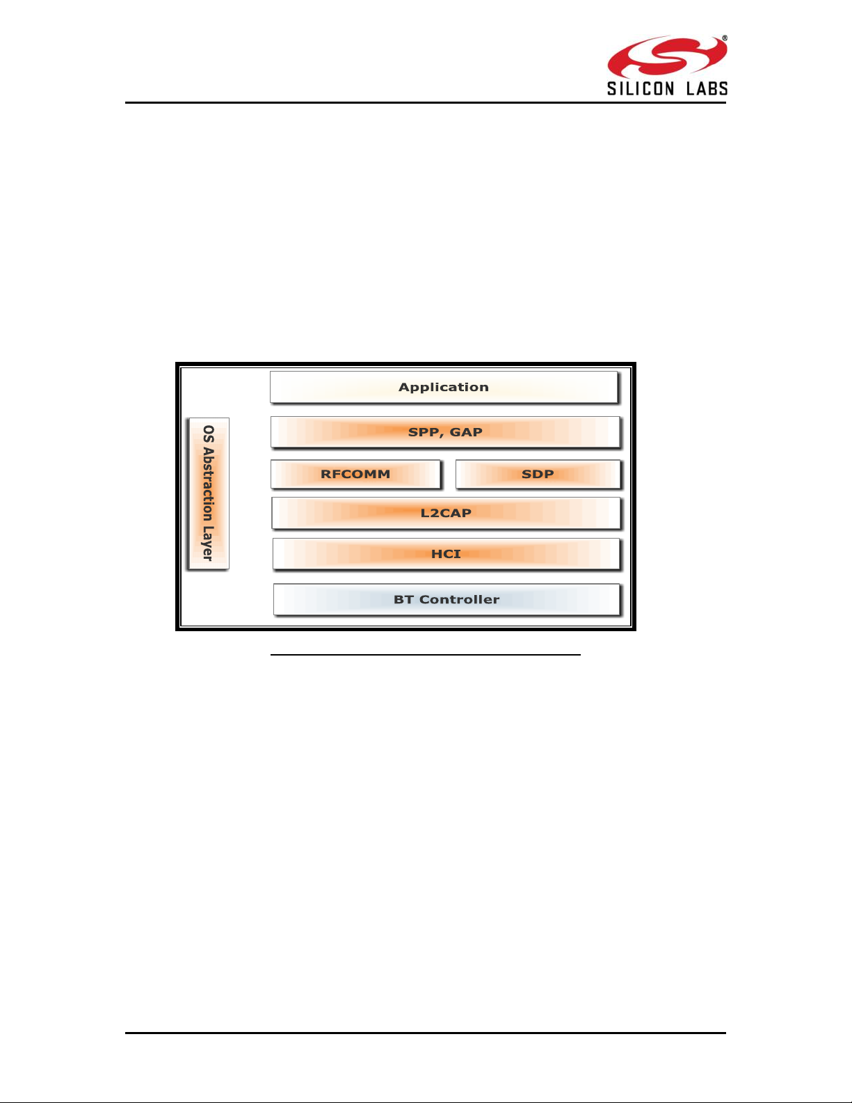
1.2 Bluetooth Software Architecture
Figure 1: Bluetooth Software Architecture Application
The application layer launches the Bluetooth stack and uses the commands to access
various profiles on the remote Bluetooth devices over the network.
1.2.1 Profiles
There are number of Bluetooth profiles defined in the Bluetooth specification. We currently
support profiles including Serial Port Profile (SPP). We provide framework to develop new
profiles very easily. We will continue to add new profiles.
1.2.2 Bluetooth Core
The Bluetooth core contains the following higher layers of the stack.
RFCOMM
SDP
1.2.3 L2CAP
HCI Generic Driver
HCI BUS Driver
silabs.com | Building a more connected world. Page 11
Page 11

RRSS99111133--WWiiSSeeCCoonnnneecct
t
TTM
M
BBlluueettooootthh CCllaassssiicc SSooffttwwaarree PPrrooggrraammmmiinngg RReeffeerreennccee
MMaannuuaall
VVeerrssiioonn 11..77..99
Frame Descriptor (16 bytes )
Frame Body (multiples of 4 bytes)
RFCOMM is a transport protocol based on L2CAP. It emulates RS-232 serial ports. The
RFCOMM protocol supports up to 60 simultaneous connections between two BT devices.
RFCOMM provides data stream interface for higher level applications and profiles.
SDP (Service Discovery Protocol) provides a means for applications to discover which
services are available and to determine the characteristics of those available services. SDP
uses an existing L2CAP connection. Further connection to Bluetooth devices can be
established using information obtained via SDP.
L2CAP (Logical Link Control and Adaptation Protocol) provides connection-oriented and
connectionless data services to upper layer protocols with data packet size up to 64 KB in
length. L2CAP performs the segmentation and reassemble of I/O packets from the
baseband controller.
HCI Generic Driver – This driver implements the HCI Interface standardized by Bluetooth
SIG. It establishes the communication between the Stack and the HCI Firmware in the
Bluetooth hardware. It communicates with the Bluetooth controller hardware via the HCI
Bus driver.
HCI Transport Layer Driver – The Bluetooth controllers are connected to the host using
interface like UART, USB, SDIO, SPI, USB-CDC etc. The HCI Transport Layer Driver provides
hardware abstraction to the rest of the Bluetooth stack software. This driver makes it
possible to use Bluetooth stack with different hardware interfaces.
1.2.4 OS Abstraction Layer
This layer abstracts RTOS services (semaphores, mutexes and critical sections) that are used
by the whole stack and the applications. The stack, which is designed in an RTOSindependent manner, can be used with any RTOS by porting this layer. It is also possible to
use the Bluetooth stack standalone without RTOS.
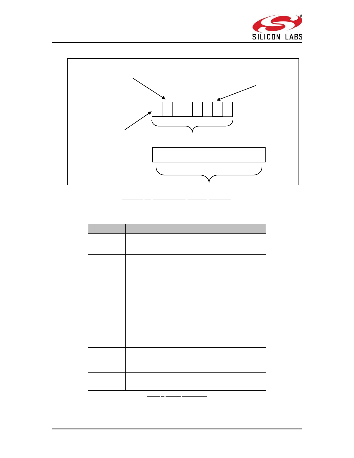
1.3 Bluetooth Command Format
This section explains the general command format. The commands should be sent to the
Module in the specified format.
The commands are sent to the module and the responses are read from the module using frame
write/frame read (as mentioned in the preceeding sections). These commands are called as
command frames.
The format of the command frames are divided into two parts:
1. Frame descriptor
2. Frame Body(Frame body is often called as Payload)
Command frame format is shown below. This description is for a Little Endian System.
silabs.com | Building a more connected world. Page 12
Page 12
RRSS99111133--WWiiSSeeCCoonnnneecct
t
TTM
M
BBlluueettooootthh CCllaassssiicc SSooffttwwaarree PPrrooggrraammmmiinngg RReeffeerreennccee
MMaannuuaall
VVeerrssiioonn 11..77..99
Word
Frame Descriptor
Word0
W0[15:0]
Bits [11:0] – Length of the frame
Bits [15:12] – 2(indicates Bluetooth packet).
Word1
W1[15:0]
Bits [15:0] - Packet type
Word2
W2[15:0]
Reserved
Word3
W3[15:0]
Reserved
Word4
W4[15:0]
Reserved
Word5
W5 [15:0]
Reserved
Word
W6 [15:0]
1. (0x0000) when sent from host to module.
2. When sent from module to host (as response frame),
it contains the status.
Word7
W7 [15:0]
Reserved
Figure 2: Command frame format
W0
W1
W2
W3
Frame Descriptor
Status word W6[15:0]
(for frames sent from module to host)
W1[15:0] Packet type
Frame Body
Payload
W5
W6
W7
W4
W0[11:0] Packet Length
W0[15:12] Queue type
The following table provides the general description of the frame descriptor.
Table 1 Frame Descriptor
silabs.com | Building a more connected world. Page 13
Page 13

RRSS99111133--WWiiSSeeCCoonnnneecct
t
TTM
M
BBlluueettooootthh CCllaassssiicc SSooffttwwaarree PPrrooggrraammmmiinngg RReeffeerreennccee
MMaannuuaall
VVeerrssiioonn 11..77..99
Command
Command ID
Set Local Name
0x0001
Query Local Name
0x0002
Set Local COD
0x0003
Query Local COD
0x0004
Query RSSI
0x0005
Query Link Quality
0x0006
Query Local BD Address
0x0007
Set Profile Mode
0x0008
Set Device Discover Mode
0x0009
Get Device Discover Mode
0x000A
Set Connection mode
0x000B
Get Connection mode
0x000C
Set Pair mode
0x000D
Get Pair mode
0x000E
Remote Name Request
0x000F
Remote Name Request Cancel
0x0010
Inquiry
0x0011
Inquiry Cancel
0x0012
Bond or Create Connection
0x0013
Three types of frames will get exchanged between the module and the
host.
1. Request/Command frames - These are sent from Host to Module. Each Request/ Command has
an asscociated response with it.
2. Response frames – These are sent from Module to Host. These are given in response to the
previous Request/Command from the Host. Each command has a single reponse.
3. Event frames – These are sent from Module to Host. These are given when
a) There are multiple reponses for a particular Request/ Command frame
b) There is Asynchonous message to be sent to host.
The following are the types of frame requests and responses and the
corresponding codes. The commands are different for both Classic and LE
modes. The below table lists the Command, Response and Event frames
in Classic mode.
In both the modes, the corresponding code is to be filled in W1 [15:0]
mentioned in the table above.
silabs.com | Building a more connected world. Page 14
Page 14

RRSS99111133--WWiiSSeeCCoonnnneecct
t
TTM
M
BBlluueettooootthh CCllaassssiicc SSooffttwwaarree PPrrooggrraammmmiinngg RReeffeerreennccee
MMaannuuaall
VVeerrssiioonn 11..77..99
Bond Cancel or Create
Connection Cancel
0x0014
Unbond or Disconnect
0x0015
Set Pin Type
0x0016
Get Pin Type
0x0017
User Confirmation
0x0018
Passkey Reply
0x0019
Pincode Reply
0x001A
Get Local Device Role
0x001B
Set Local Device Role
0x001C
Get Service List
0X001D
Search Service
0X001E
SPP connect
0X001F
SPP Disconnect
0X0020
SPP Transfer
0X0021
Initialize BLE module
0x008D
Deinitialize BLE module
0x008E
Antenna Select
0x008F
Linkkey Reply
0x0091
PER Transmit
0x0098
PER Receive
0x0099
PER Stats
0x009A
PER CW mode
0x009B
Sniff Mode
0x009D
Sniff Exit
0x009E
Sniff Subrating
0x009F
Feature Bit map
0x00A6
Set antenna Tx power level
0x00A7
Set EIR data
0x00A9
Response
Response ID
Card ready
0x0505
Set Local Name
0x0001
Query Local Name
0x0002
Set Local COD
0x0003
Query Local COD
0x0004
Table 2 Command IDs in BT Classic mode
silabs.com | Building a more connected world. Page 15
Page 15

RRSS99111133--WWiiSSeeCCoonnnneecct
t
TTM
M
BBlluueettooootthh CCllaassssiicc SSooffttwwaarree PPrrooggrraammmmiinngg RReeffeerreennccee
MMaannuuaall
VVeerrssiioonn 11..77..99
Query RSSI
0x0005
Query Link Quality
0x0006
Query Local BD Address
0x0007
Set Profile Mode
0x0008
Set Device Discover Mode
0x0009
Get Device Discover Mode
0x000A
Set Connection mode
0x000B
Get Connection mode
0x000C
Set Pair mode
0x000D
Get Pair mode
0x000E
Remote Name Request
0x000F
Remote Name Request Cancel
0x0010
Inquiry
0x0011
Inquiry Cancel
0x0012
Bond or Create Connection
0x0013
Bond Cancel or Create
Connection Cancel
0x0014
Unbond or Disconnect
0x0015
Set Pin Type
0x0016
Get Pin Type
0x0017
User Confirmation
0x0018
Passkey reply
0x0019
Pincode Reply
0x001A
Get Local Device Role
0x001B
Set Local Device Role
0x001C
Get Service List
0X001D
Search Service
0X001E
SPP connect
0X001F
SPP Disconnect
0X0020
SPP Transfer
0X0021
BT Classic init
0x008D
BT Classic deint
0x008E
Antenna Select
0x008F
Linkkey Reply
0x0091
PER Transmit
0x0098
PER Recieve
0x0099
PER Stats
0x009A
PER CW mode
0x009B
silabs.com | Building a more connected world. Page 16
Page 16

RRSS99111133--WWiiSSeeCCoonnnneecct
t
TTM
M
BBlluueettooootthh CCllaassssiicc SSooffttwwaarree PPrrooggrraammmmiinngg RReeffeerreennccee
MMaannuuaall
VVeerrssiioonn 11..77..99
SSP Mode
0x00A0
Sniff Mode
0x009D
Sniff Exit
0x009E
Sniff Subrating
0x009F
Feature Bit Map
0x00A6
Set antenna Tx power level
0x00A7
Set EIR data
0x00A9
Event
Event ID
Role change status
0x1000
Unbond or Disconnect
0x1001
Bond Response
0x1002
Inquiry response
0x1003
Remote Device Name
0x1004
Remote Name Request cancelled
0x1005
Disconnected
0x1006
User confirmation request
0x1007
User passkey display
0x1008
User pincode request
0x1009
User passkey request
0x100A
Inquiry complete
0x100B
Auth complete
0x100C
User linkkey request
0x100D
User linkkey save
0x100E
SPP Receive
0x1100
SPP connected
0x1101
SPP Disconnected
0x1102
Mode Changed
0x1010
Sniff Subrating Changed
0x1011
Table 3 Response IDs in BT Classic mode
Table 4 Event IDs in BT Classic mode
1.4 Interfaces
Host can interface with RS9113-WiSeConnect Module using following list
of host interfaces to configure and send/receive data.
UART
SPI
silabs.com | Building a more connected world. Page 17
Page 17
RRSS99111133--WWiiSSeeCCoonnnneecct
t
TTM
M
BBlluueettooootthh CCllaassssiicc SSooffttwwaarree PPrrooggrraammmmiinngg RReeffeerreennccee
MMaannuuaall
VVeerrssiioonn 11..77..99
1.4.1 UART
SPI
SPI
Host
INTERRUPT
UART
UART
RS9113-WisConnect Module
USB
USB
The UART on the RS9113-WiSeConnect module is used as a host
interface to configure the module, send and receive data.
USB
Features
Supports hardware (RTS/CTS) flow control.
Supports following list of baud rates
o 9600 bps
o 19200 bps
o 38400 bps
o 57600 bps
o 115200 bps
o 230400 bps
o 460800 bps
NOTE: For BT/ BLE there is no support for 921600 bps
Default Parameters
Data bits - 8
Stop bits - 1
Parity – None
Flow control - None
1.4.2 USB
RS9113-WiSeConnect module supports USB interface, allow host to
configure and send/receive data through module using USB interface.
Features
USB 2.0 (USB-HS core)
silabs.com | Building a more connected world. Page 18
Page 18

RRSS99111133--WWiiSSeeCCoonnnneecct
t
TTM
M
BBlluueettooootthh CCllaassssiicc SSooffttwwaarree PPrrooggrraammmmiinngg RReeffeerreennccee
MMaannuuaall
VVeerrssiioonn 11..77..99
o USB 2.0 offers the user a longer bandwidth with increasing
data throughput.
o USB 2.0 supports additional data rate of 480 Mbits/Sec in
addition to 1.5Mbits/Sec and 12 Mbits/Sec.
Supports USB-CDC
1.4.3 SPI
This section describes RS9113-WiSeConnect module SPI interface and the
commands & processes to operate the module using the SPI interface.
Features
Supports 8-bit and 32-bit data mode
Supports flow control
Communication through SPI
The RS9113-WiSeConnect module can be configured and operated from
the Host by sending commands through the SPI interface.
SPI Settings
The SPI Interface is a full duplex serial Host interface, which supports 8bit and 32-bit data mode. The SPI interface of the module consists of the
following signals:
SPI_MOSI (Input) – Serial data input for the module.
SPI_MISO (Output) – Serial data output for the module.
SPI_CS (Input) – Active low slave select signal. This should be low when
SPI transactions are to be carried out.
SPI_CLK (Input) – SPI clock. Maximum value allowed is 80 MHz
INTR (Output) – Active high (Default), Active low, level interrupt output
from the module.
The module acts as a SPI slave only while the Host is the SPI master.
Following parameters should be in the host SPI interface.
CPOL (clock polarity) = 0,
CPHA (clock phase) = 0.
Interrupt
The module’s INTERRUPT output signal should be connected to the
interrupt input of the Host MCU. The INTERRUPT signal is an active
high, level triggered signal. It is raised by the module in the following
cases:
1) When the module needs to indicate to the Host that it has received
data from the remote terminal and the data needs to be read by the
Host.
2) When the module needs to indicate to the Host that a response to a
command sent by the Host is ready to be read from the module.
silabs.com | Building a more connected world. Page 19
Page 19

RRSS99111133--WWiiSSeeCCoonnnneecct
t
TTM
M
BBlluueettooootthh CCllaassssiicc SSooffttwwaarree PPrrooggrraammmmiinngg RReeffeerreennccee
MMaannuuaall
VVeerrssiioonn 11..77..99
To indicate to the Host that it should read a CARD READY message from
module. This operation is described in the subsequent sections.
1.5 Bluetooth Classic commands
The following sections will explain various RS9113-WiSeConnect Bluetooth Classic
commands, their structures, the parameters they take and their responses. For API
prototypes of these commands, please refer to the API Library Section
Note: All BT/BLE AT command are case sensitive and lower case.
NOTE:
1. A new command has to be called only after getting the response for the previous
command
2. In the following commands, wherever the BD Address is applicable, it should be given in
hex format and upper case characters
Please refer to the example commands in each section for more information.
1.5.1 Generic commands
1.5.1.1 Set Operating Mode
Description:
This is the first command that needs to be sent from the Host after receiving card ready
frame from module. This command configures the module in different functional modes.
Command Format:
AT Mode:
at+rsi_opermode=<oper_mode>,<feature_bit_map>,<tcp_ip_feature_bit_map>,<custom_f
eature_bit_map>,<ext_custom_feature_bit_map>,< bt_custom_feature_bit_map>r\n
Binary Mode:
The structure of the payload is give below
typedef struct
{
uint32 oper_mode;
uint32 feature_bit_map;
uint32 tcp_ip_feature_bit_map;
uint32 custom_feature_bit_map;
uint32 ext_custom_feature_bit_map;
uint32 bt_custom_feature_bit_map;
uint32 ext_tcp_ip_feature_bitmap;
} operModeFrameSnd;
silabs.com | Building a more connected world. Page 20
Page 20

RRSS99111133--WWiiSSeeCCoonnnneecct
t
TTM
M
BBlluueettooootthh CCllaassssiicc SSooffttwwaarree PPrrooggrraammmmiinngg RReeffeerreennccee
MMaannuuaall
VVeerrssiioonn 11..77..99
Command Parameters:
Oper_mode:
Sets the mode of operation. oper_mode contains two parts <wifi_oper_mode,
coex_mode>. Lower two bytes represent wifi_oper_mode and higher two bytes represent
coex_modes.
oper_mode = ((wifi_oper_mode) | (coex_mode << 16))
Wifi_oper_mode values:
0 - Wi-Fi Client Mode. The module works as a normal client that can connect to an Access
Point with different security modes other than enterprise security.
1 – Wi-Fi Direct™ or Autonomous GO. In this mode, the module either acts as a Wi-Fi Direct
node or as an Autonomous GO (with intent value 16), depending on the inputs supplied for
the command “Configure Wi-Fi Direct Peer-to-Peer Mode” in RS9113-WiseConnect-
Software-PRM-v1.7.6.pdf at docs folder in release package.
. In Autonomous GO and in Wi-Fi Direct GO mode, a maximum of 4 client devices are
supported.
2 – Enterprise Security Client Mode. The module works as a client that can connect to an
Access Point with WPA/WPA2-Enterprise security.
6 – Access Point mode. In this mode, the module acts as an Access Point, depending on the
inputs supplied for the command “Configure AP Mode” in RS9113-WiseConnect-Software-
PRM-v1.7.6.pdf at docs folder in release package.
. In Access Point mode, a maximum of 8 client devices are supported.
8 - PER Mode. This mode is used for calculating packet error rate and mostly used during RF
certification tests.
9 – Concurrent mode. This mode is used to run module in concurrent mode. In concurrent
mode, host can connect to a AP and can create AP simultaneously.
NOTE: In concurrent mode
1. AP MAC address last byte will differ and it will be one plus the station mode MAC last
byte.
2. In TCP/IP non bypass mode, Broadcast/Multicast packet will go to first created
interface (e.g. if Station mode connects first the broadcast/multicast packet will go to
network belonging to station mode).
3. IPV6 support is not present in the current release.
coex_mode bit values: enables respective protocol
BIT 0 : Enable/Disable WLAN mode.
0 – Disable WLAN mode
1 – Enable WLAN mode
BIT 1 : Enable/Disable ZigBee mode.
0 – Disable ZigBee mode
silabs.com | Building a more connected world. Page 21
Page 21

RRSS99111133--WWiiSSeeCCoonnnneecct
t
TTM
M
BBlluueettooootthh CCllaassssiicc SSooffttwwaarree PPrrooggrraammmmiinngg RReeffeerreennccee
MMaannuuaall
VVeerrssiioonn 11..77..99
Coex_mode
Description
0
WLAN only mode
3
WLAN and ZigBee coexistence mode.
5
WLAN and BT coexistence mode.
13
WLAN and BTLE coexistence mode.
14
BTLE and ZigBee coexistence mode.
1 – Enable ZigBee mode
BIT 2 : Enable/Disable BT mode.
0 – Disable BT mode
1 – Enable BT mode
BIT 3 : Enable/Disable BTLE mode.
0 – Disable BTLE mode
1 – Enable BTLE mode
NOTE: In BTLE mode, need to enable BT mode also.
Following table represents possible coex modes supported:
Table 5: Coex Modes Supported
NOTE: Following CoeX mode is supported currently
1. WLAN STA+BT (Only TCP/IP Bypass mode)
2. WLAN STA + BLE
3. WLAN STA + ZB
4. BLE + ZB
5. WLAN AP + BT (Only support is present in TCP/IP Bypass mode)
6. WLAN AP + BLE
7. WLAN AP + ZB
To select proper CoeX mode please refer
WiSeConnect_TCPIP_Feature_Selection_v1.7.6.xlsx at docs folder given in the release
package
NOTE: If coex mode enabled in opermode command, then BT/BLE or ZigBee protocol will
start and give corresponding card ready in parallel with opermode command response
(which will be handled by corresponding application).
BT card ready frame is described in
RS9113-WiseConnect-BT-Classic-Software-PRM-API-Guide-v1.7.6.pdf ,
BLE card ready frame is described in
RS9113-WiseConnect-BLE-Software-PRM-API-Guide-v1.7.6.pdf
silabs.com | Building a more connected world. Page 22
Page 22

RRSS99111133--WWiiSSeeCCoonnnneecct
t
TTM
M
BBlluueettooootthh CCllaassssiicc SSooffttwwaarree PPrrooggrraammmmiinngg RReeffeerreennccee
MMaannuuaall
VVeerrssiioonn 11..77..99
and ZigBee card ready frame is described in
RS9113-WiseConnect-ZigBee-Software-PRM-API-Guide-v1.7.6.pdf
at docs folder in release package.
feature_bit_map: this bitmap is used to enable following WLAN features:
feature_bit_map[0]- To enable open mode
0 - Open Mode Disabled
1- Open Mode enabled (No Security)
feature_bit_map[1]- To enable PSK security
0 - PSK security disabled
1 - PSK security enabled
feature_bit_map[2]-To enable Aggregation in station mode
0-Aggregation disabled
1-Aggregation enabled
feature_bit_map[3]-To enable LP GPIO hand shake
0 – LP GPIO hand shake disabled
1 – LP GPIO hand shake enabled
feature_bit_map[4]-To enable ULP GPIO hand shake
0 – ULP GPIO hand shake disabled
1 – ULP GPIO hand shake enabled
feature_bit_map[5]-To select module to host wakeup pin
0 – GPIO_21 is used as module to host wakeup pin
1 – ULP_GPIO_1 is used as module to host wakeup pin
feature_bit_map[6]-To select RF supply voltage
0 – RF voltage is set to 1.9V
1 – RF voltage is set to 3.3V
feature_bit_map[7]-To disable WPS support
0 – WPS enable
1 - WPS disable in AP mode and station Mode
feature_bit_map[8:31]- Reserved. Should set to be ‘0’
NOTE: feature_bit_map[0], feature_bit_map[1] are valid only in Wi-Fi client mode.
tcp_ip_feature_bit_map: To enable TCP/IP related features.
tcp_ip_feature_bit_map[0]- To enable TCP/IP bypass
0 - TCP/IP bypass mode disabled
silabs.com | Building a more connected world. Page 23
Page 23

RRSS99111133--WWiiSSeeCCoonnnneecct
t
TTM
M
BBlluueettooootthh CCllaassssiicc SSooffttwwaarree PPrrooggrraammmmiinngg RReeffeerreennccee
MMaannuuaall
VVeerrssiioonn 11..77..99
1 - TCP/IP bypass mode enabled
tcp_ip_feature_bit_map[1]- To enable http server
0 - HTTP server disabled
1 - HTTP server enabled
tcp_ip_feature_bit_map[2]- To enable DHCPv4 client
0 - DHCPv4 client disabled
1 - DHCPv4 client enabled
tcp_ip_feature_bit_map[3]- To enable DHCPv6 client
0 - DHCPv6 client disabled
1 - DHCPv6 client enabled
tcp_ip_feature_bit_map[4]- To enable DHCPv4 server
0 - DHCPv4 server disabled
1 - DHCPv4 server enabled
tcp_ip_feature_bit_map[5]- To enable DHCPv6 server
0 - DHCPv6 server disabled
1 - DHCPv6 server enabled
tcp_ip_feature_bit_map[6]- To enable Dynamic update of web pages (JSON objects)
0 - JSON objects disabled
1 - JSON objects enabled
tcp_ip_feature_bit_map[7]- To enable HTTP client
0 - To disable HTTP client
1 - To enable HTTP client
tcp_ip_feature_bit_map[8]- To enable DNS client
0 - To disable DNS client
1 - To enable DNS client
tcp_ip_feature_bit_map[9]- To enable SNMP agent
0 - To disable SNMP agent
1 - To enable SNMP agent
tcp_ip_feature_bit_map[10]- To enable SSL
0 - To disable SSL
1 - To enable SSL
tcp_ip_feature_bit_map[11]- To enable PING from module(ICMP)
0 - To disable ICMP
1 - To enable ICMP
tcp_ip_feature_bit_map[12]- To enable HTTPS Server
silabs.com | Building a more connected world. Page 24
Page 24

RRSS99111133--WWiiSSeeCCoonnnneecct
t
TTM
M
BBlluueettooootthh CCllaassssiicc SSooffttwwaarree PPrrooggrraammmmiinngg RReeffeerreennccee
MMaannuuaall
VVeerrssiioonn 11..77..99
0 - To disable HTTPS Server
1 - To enable HTTPS Server
tcp_ip_feature_bit_map[14]- To send configuration details to host on submitting
configurations on wireless configuration page
0 - Do not send configuration details to host
1 - Send configuration details to host
tcp_ip_feature_bit_map[15]- To enable FTP client
0 - To disable FTP client
1 - To enable FTP client
tcp_ip_feature_bit_map[16]- To enable SNTP client
0 - To disable SNTP client
1 - To enable SNTP client
tcp_ip_feature_bit_map[17]- To enable IPv6 mode
0 - To disable IPv6 mode
1 - To enable IPv6 mode
IPv6 will also get enabled if DHCP v6 client/DHCP v6 server is enabled irrespective of
tcp_ip_feature_bit_map[17].
tcp_ip_feature_bit_map[19]- To MDNS and DNS-SD
0 - To disable MDNS and DNS-SD
1 - To Enable MDNS and DNS-SD
tcp_ip_feature_bit_map[20]- To enable SMTP client
0 - To disable SMTP client
1 - To Enable SMTP client
tcp_ip_feature_bit_map[21 - 24]- To select no of sockets
possible values are 1 to 10 . If User tried to select more than 10 sockets it will be reset to 10
sockets only . Default no of sockets is 10, if this selection is not done by the user.
tcp_ip_feature_bit_map[25]- To select Single SSL socket
0 – selecting single socket is Disabled
1- Selecting single socket is enabled
NOTE: By default two SSL sockets are supported
tcp_ip_feature_bit_map[26]- To allow loading Private & Public certificates
0 – Disable loading private & public certificates
1- Allow loading private & public certificates
silabs.com | Building a more connected world. Page 25
Page 25

RRSS99111133--WWiiSSeeCCoonnnneecct
t
TTM
M
BBlluueettooootthh CCllaassssiicc SSooffttwwaarree PPrrooggrraammmmiinngg RReeffeerreennccee
MMaannuuaall
VVeerrssiioonn 11..77..99
NOTE : If Secure handshake is with CA – certificate alone , then disable loading Private and
public keys and erase these certificates from the flash using load_cert API .
Or if Secure handshake needed verification of Private and Public keys , then enable loading
of private and public keys.
tcp_ip_feature_bit_map[27]- To load SSL certificate on to the RAM
tcp_ip_feature_bit_map[28]- To enable TCP-IP data packet Dump on UART2
tcp_ip_feature_bit_map[29]- To enable POP3 client
0 - To disable POP3 client
1 - To Enable POP3 client
tcp_ip_feature_bit_map[13], tcp_ip_feature_bit_map[18], tcp_ip_feature_bit_map[30:31]-All
set to ‘0’.
NOTE:
SSL(tcp_ip_feature_bit_map[10], tcp_ip_feature_bit_map[12]) is supported only in
opermode 0
NOTE:
Feature selection utility is provided in the package. WiSeConnect device supports the
selected features combination only if it is feasible according to the
WiSeConnect_TCPIP_Feature_Selection_v1.7.6.xlsx at docs folder given in the release
package.
custom_feature_bit_map:
This bitmap used to enable following custom features:
BIT[2]: If this bit is set to ‘1’, the DHCP server behavior, when the module is in AP mode,
changes. The DHCP server, when it assigns IP addresses to the client nodes, does not send
out a Gateway address, and sends only the assigned IP and Subnet values to the client. It is
highly recommended to keep this value at ‘0’ as the changed behavior is required in only
very specialised use cases and not in normal AP functionality. The default value of this bit is
‘0’.
BIT[5]: If this bit is set to ‘1’, Hidden SSID is enabled in case of AP mode. The default value of
this bit is ‘0’.
BIT[6]:To enable/disable DNS server IP address in DHCP offer response in AP mode.
1- In AP mode, DHCP server sends DNS server IP address in DHCP offer
0- Not to include DNS server address in DHCP offer response
BIT[8]: - Enable/Disable DFS channel passive scan support
1- Enable
0-Disable
BIT[9] : – To Enable/disable LED(GPIO_16) after module initialization(INIT).
1- Enable LED support
silabs.com | Building a more connected world. Page 26
Page 26

RRSS99111133--WWiiSSeeCCoonnnneecct
t
TTM
M
BBlluueettooootthh CCllaassssiicc SSooffttwwaarree PPrrooggrraammmmiinngg RReeffeerreennccee
MMaannuuaall
VVeerrssiioonn 11..77..99
0– Disable LED support
BIT[10]: Used to enable/disable Asynchronous messages to host to indicate the module
state.
1- Enable asynchronous message to host
0-Disable asynchronous message to host
BIT[11] : To enable/disable packet pending (Wakeon wireless) indication in UART mode
1 – Enable packet pending indication
0- Disable packet pending indication
BIT[12]:Used to enable or disable AP blacklist feature in client mode during roaming or
rejoin. By default module maintains AP blacklist internally to avoid some access points.
1 – Disable AP black list feature
0 – Enable AP black list feature
BIT[13-16]:Used to set the maximum number of stations or client to support in AP or Wi-Fi
Direct mode. Possible values are 1 to 8 in AP mode and 1 to 4 in Wi-Fi Direct mode.
Note1: If these bits are not set, default maximum clients supported is set to 4.
BIT[17] : to select between de-authentication or Null data (with power management bit
set) based roaming, Depending on selected method station will send deauth or Null data to
connected AP when roam from connected AP to newly selected AP.
0 – To enable de-authentication based roaming
1 – To enable Null data based roaming
BIT[18]: Reserved
BIT[19]: Reserved
BIT[20]: Used to start/stop auto connection process on bootup, until host triggers it using
Trigger Auto Configuration command
1 – Enable
0 – Disable
BIT[22]: Used to enable per station power save packet buffer limit in AP mode. When
enabled, only two packets per station will be buffered when station is in power save
1 – Enable
0 – Disable
BIT[23] : To enable/disable HTTP/HTTPs authentication
1 - Enable
0 – Disable
BIT[24]: To enable/disable higher clock frequency in module to improve throughputs
1 - Enable
0 – Disable
BIT[25]: To give HTTP server credentials to host in get configuration command
silabs.com | Building a more connected world. Page 27
Page 27

RRSS99111133--WWiiSSeeCCoonnnneecct
t
TTM
M
BBlluueettooootthh CCllaassssiicc SSooffttwwaarree PPrrooggrraammmmiinngg RReeffeerreennccee
MMaannuuaall
VVeerrssiioonn 11..77..99
1 – To include HTTP server credentials in get configuration command response
0 – To exclude HTTP server credentials in get configuration command response
BIT[26]: To accept or reject new connection request when maximum clients are connected
in case of LTCP.
1 - Reject
0 – Accept
By default this bit value is zero.
When BIT[26] is zero: For a LTCP socket when maximum clients are connected if a new
connection request is received, then this connection request will not be rejected.
Instead module will maintain this connection request in LTCP pending list.
This request will be served when any of the connected client is disconnected.
When BIT[26] is set: For a LTCP socket when maximum clients are connected if a new
connection request is received, then this connection request will be rejected
immediately. Module will not maintain this connection request in LTCP pending list.
BIT[27]: To enable dual band roaming and rejoin feature this bit is used.
1 - Enable dual band roaming and rejoin
0 – Disable dual band roaming and rejoin.
BIT[28]: To enable real time clock from host
1 - Enable real time clock feature given by host
0 – Disable real time clock feature
BIT[29]: To Enable IAP support in BT mode
1 - Enable
0 – Disable
BIT[31]: This bit is used to validate extended custom feature bitmap.
1 – Extended feature bitmap valid
0 – Extended feature bitmap is invalid
BIT[0:1],BIT[3:4],BIT[7],BIT[21], BIT[30]: Reserved, should be set to all ‘0’.
NOTE: For UART/USB-CDC in AT mode:
When user does not give any tcp_ip_feature_bit_map value then default settings for client
mode, Enterprise client mode, WiFi-Direct mode are:
HTTP server, DHCPv4 client, DHCPv6 client and JSON objects are enabled.
When user does not give any tcp_ip_feature_bit_map value then default settings for Access
point mode are:
HTTP server, DHCPv4 server, DHCPv6 server and JSON objects are enabled.
Parameters- feature_bit_map, tcp_ip_feature_bit_map and custom_feature_bit_map are
optional in opermode command in UART mode for AT mode. If user does not give these
parameters then default configuration gets selected, as explained above, based upon the
operating mode configured.
silabs.com | Building a more connected world. Page 28
Page 28

RRSS99111133--WWiiSSeeCCoonnnneecct
t
TTM
M
BBlluueettooootthh CCllaassssiicc SSooffttwwaarree PPrrooggrraammmmiinngg RReeffeerreennccee
MMaannuuaall
VVeerrssiioonn 11..77..99
Result Code
Description
OK
Successful execution of the command
ERROR<Error code>
Failure
If opermode is 8 (PER mode is selected) - feature_bit_map, tcp_ip_feature_bit_map and
custom_feature_bit_map can be ignored or not valid. Set to zero.
ext_custom_feature_bit_map:
This feature bitmap is extention of custom feature bitmap and is valid only if BIT[31] of
custom feature bitmap is set. This enables the following feature.
BIT[0]: To enable antenna diversity feaute.
1 – Enable antenna diversity feature
0 – Disble antenna diversity feature
BIT[1]:This bit is used to enable 4096 bit RSA key support
1 – Enable 4096 bit RSA key support
0 – Disable 4096 bit RSA key support
Note: This bit is required to set for 4096 bit RSA key support. If key size is 4096 bit, module
will use software rountine for exponentiation, so connection time will increase.
BIT[2]:This bit is used to set the module type.This is applicable only if manufacturing
software version of the module is below 3.1 (i.e. manufacturing version 3 and
subversion 1).
0 - Module will ignore the module type given through the set region
command.
1 - Module will accept the module type given through the set region
command.
bt_custom_feature_bit_map:
Currently this bitmap is not valid in case of BT-Classic.
Response:
AT Mode:
Binary Mode:
There is no response payload for this command.
Example:
AT Mode:
at+rsi_opermode=327680,0,1,0\r\n
Response:
OK
bt_loaded\r\n
silabs.com | Building a more connected world. Page 29
Page 29

RRSS99111133--WWiiSSeeCCoonnnneecct
t
TTM
M
BBlluueettooootthh CCllaassssiicc SSooffttwwaarree PPrrooggrraammmmiinngg RReeffeerreennccee
MMaannuuaall
VVeerrssiioonn 11..77..99
1.5.1.2 Set Local name
Result Code
Description
OK <name_length>,<local_device_name>
Command Success.
ERROR <Error_code>
Command Fail.
Description: This is used to set name to the local device.
Binary Payload Structure:
typedef struct rsi_bt_cmd_set_local_name {
UINT08 NameLength;
INT08 Name[50];
} RSI_BT_CMD_SET_LOCAL_NAME;
AT command format:
at+rsibt_setlocalname=<NameLength>,<Name>\r\n
Parameters:
NameLength – Length of the name of the local device.
Name – Name of the local device.
Response Payload:
There is no response payload for this command.
AT command Ex: at+rsibt_setlocalname=8,redpines\r\n
Response: OK\r\n
NOTE: Namelength parameter should be in decimal format.
1.5.1.3 Query Local name
Description: This is used to query the name of the local device.
Binary Payload Structure:
No Payload required.
AT command format:
at+rsibt_getlocalname?\r\n
Response Payload:
typedef struct rsi_bt_resp_query_local_name {
UINT08 NameLength;
INT08 Name[50];
} RSI_BT_RESP_QUERY_LOCAL_NAME;
Response Parameters:
NameLength – Length of the name of the local device.
Name – Name of the local device.
silabs.com | Building a more connected world. Page 30
Page 30

RRSS99111133--WWiiSSeeCCoonnnneecct
t
TTM
M
BBlluueettooootthh CCllaassssiicc SSooffttwwaarree PPrrooggrraammmmiinngg RReeffeerreennccee
MMaannuuaall
VVeerrssiioonn 11..77..99
AT command Ex: at+rsibt_getlocalname?\r\n
Result Code
Description
OK <local_device_class>
Command Success.
ERROR <Error_code>
Command Fail.
Response: OK 8,redpines\r\n
1.5.1.4 Set Local COD
Description: This is used to indicate the capabilities of the local device to other devices.
It is a parameter received during the device discovery procedure on the BR/EDR physical
transport, indicating the type of device. The Class of Device parameter is only used on
BR/EDR and BR/EDR/LE devices using the BR/EDR physical transport.
Binary Payload Structure:
typedef struct rsi_bt_cmd_set_local_cod {
UINT32 LocalCOD;
} RSI_BT_CMD_SET_LOCAL_COD;
AT command format:
at+rsibt_setlocalcod=<local_device_class>\r\n
Parameters:
Local COD – Class of the Device of the local device
Response Payload:
There is no response payload for this command.
AT command Ex: at+rsibt_setlocalcod=7A020C\r\n
Response: OK\r\n
1.5.1.5 Query Local COD
Description: This is used to query Class of Device of the local device.
Binary Payload Structure:
No Payload required.
AT command format:
at+rsibt_getlocalcod?\r\n
Response Payload:
typedef struct rsi_bt_resp_query_local_cod {
UINT32 LocalCOD;
} RSI_BT_RESP_QUERY_LOCAL_COD;
Response Parameters:
LocalCOD – Class of the Device of the local device
silabs.com | Building a more connected world. Page 31
Page 31

RRSS99111133--WWiiSSeeCCoonnnneecct
t
TTM
M
BBlluueettooootthh CCllaassssiicc SSooffttwwaarree PPrrooggrraammmmiinngg RReeffeerreennccee
MMaannuuaall
VVeerrssiioonn 11..77..99
AT command Ex: at+rsibt_getlocalcod?\r\n
Result Code
Description
OK <rssi value>
Command Success.
ERROR <Error_code>
Command Fail.
Response: OK 7A020C\r\n
1.5.1.6 Query RSSI
Description: This is used to query RSSI of the connected remote BT Device.
Binary Payload Structure:
typedef struct rsi_bt_cmd_query_rssi {
UINT08 BDAddress[6];
} RSI_BT_CMD_QUERY_RSSI;
AT command format:
at+rsibt_getrssi=<BDAddress>?\r\n
Parameters:
BDAddress – BD Address of the connected remote device.
Response Payload:
typedef struct rsi_bt_resp_query_rssi {
UINT08 RSSI;
} RSI_BT_RESP_QUERY_RSSI;
Response parameters:
RSSI – RSSI value of the connected remote device.
AT command Ex: at+rsibt_getrssi=AA-BB-CC-DD-EE-FF?\r\n
Response: OK 230\r\n
1.5.1.7 Query Link Quality
1
Description: This is used to query the link quality between the local device and the connected
remote device.
Binary Payload Structure:
typedef struct rsi_bt_cmd_query_link_quality {
UINT08 BDAddress[6];
} RSI_BT_CMD_QUERY_LINK_QUALITY;
AT command format:
at+rsibt_getlinkqlty=<BDAddress>?\r\n
Parameters:
BDAddress – BD Address of the connected remote device
1
This command is not currently supported.
silabs.com | Building a more connected world. Page 32
Page 32

RRSS99111133--WWiiSSeeCCoonnnneecct
t
TTM
M
BBlluueettooootthh CCllaassssiicc SSooffttwwaarree PPrrooggrraammmmiinngg RReeffeerreennccee
MMaannuuaall
VVeerrssiioonn 11..77..99
Response Payload:
Result Code
Description
OK <link_quality>
Command Success with valid response.
ERROR <Error_code>
Command Fail.
Result Code
Description
OK <bd_addr>
Command Success with valid response.
ERROR <Error_code>
Command Fail.
typedef struct rsi_bt_resp_query_link_quality {
UINT08 LinkQuality;
} RSI_BT_RESP_QUERY_LINK_QUALITY;
Response parameters:
LinkQuality – Link quality value.
AT command Ex: at+rsibt_getlinkqlty=AA-BB-CC-DD-EE-FF?\r\n
Response: OK 123\r\n
1.5.1.8 Query Local BD Address
Description: This is used to query the BD address of the local device.
Binary Payload Structure:
No Payload required.
AT command format:
at+rsibt_getlocalbdaddr?\r\n
Response Payload:
typedef struct rsi_bt_resp_query_local_bd_address {
UINT08 BDAddress[6];
} RSI_BT_RESP_QUERY_LOCAL_BD_ADDRESS;
Response Parameters:
BDAddress - BD Address of the local device
AT command Ex: at+rsibt_getlocalbdaddr?\r\n
Response: OK AA-BB-CC-DD-EE-FF\r\n
1.5.1.9 Initialize BT module
Description: This is used to initialize the BT module.
silabs.com | Building a more connected world. Page 33
Page 33

RRSS99111133--WWiiSSeeCCoonnnneecct
t
TTM
M
BBlluueettooootthh CCllaassssiicc SSooffttwwaarree PPrrooggrraammmmiinngg RReeffeerreennccee
MMaannuuaall
VVeerrssiioonn 11..77..99
Binary Payload Structure:
No Payload required
AT command format:.
at+rsibt_btinit\r\n
Response Payload:
There is no response payload for this command.
AT command Ex: at+rsibt_btinit\r\n
Response: OK\r\n
1.5.1.10 Deinitialize BT module
Description: This is used to deinitialize the BT module.To again initialize the module
Initialize BT module command is used.
Binary Payload Structure:
No Payload required
AT command format:
at+rsibt_btdeinit\r\n
Payload Structure:
No Payload required.
Response Payload:
There is no response payload for this command.
AT command Ex: at+rsibt_btdeinit\r\n
Response: OK\r\n
1.5.1.11 BT Antenna Select
Description: This is used to select the internal or external antenna of the BT module.
Binary Payload Structure:
typedef struct rsi_bt_cmd_antenna_select{
UINT08 AntennaVal;
} RSI_BT_CMD_ANTENNA_SELECT;
AT command format:
at+rsibt_btantennaselect=<antenna_val>\r\n
Parameters:
AntennaVal – To select the internal or external antenna
0 – Internal Antenna.
1 – External Antenna.
Response Payload:
silabs.com | Building a more connected world. Page 34
Page 34

RRSS99111133--WWiiSSeeCCoonnnneecct
t
TTM
M
BBlluueettooootthh CCllaassssiicc SSooffttwwaarree PPrrooggrraammmmiinngg RReeffeerreennccee
MMaannuuaall
VVeerrssiioonn 11..77..99
There is no response payload for this command.
AT command Ex: at+rsibt_btantennaselect=1\r\n
Response: OK\r\n
1.5.1.12 Set Feature Bitmap
Description: This is used to enable/disable the features.
Binary Payload Structure:
typedef union
{
struct {
UINT32 Feature_BitMap;
} BitMapFrameSend;
UINT08 uFeatureBitMapBuf[2];
} RSI_BT_CMD_FEATURE_BIT_MAP
AT command format:
at+rsibt_setfeaturebitmap=<featurebitmap>\r\n
Parameters:
featurebitmap –
1 – Enable BT security
0 – Disable BT security
Response Payload:
There is no response payload for this command
ATcommandEx:
at+rsibt_setfeaturebitmap =1\r\n
Response: OK\r\n
1.5.1.13 Set Antenna Tx power level
Description: This is used to set the Bluetooth antenna transmit power level.
Binary Payload Structure:
typedef struct rsi_bt_cmd_set_antenna_tx_power_level {
UINT08 protocol_mode;
INT08 tx_power;
} RSI_BT_CMD_SET_ANTENNA_TX_POWER_LEVEL;
AT command format:
at+rsibt_setantennatxpowerlevel=<protocol_mode>,<power_level>\r\n
Parameters:
protocol_mode –
1 –BT Classic
Power_level -
silabs.com | Building a more connected world. Page 35
Page 35

RRSS99111133--WWiiSSeeCCoonnnneecct
t
TTM
M
BBlluueettooootthh CCllaassssiicc SSooffttwwaarree PPrrooggrraammmmiinngg RReeffeerreennccee
MMaannuuaall
VVeerrssiioonn 11..77..99
Bit No
Description
0
SPP Profile
1
A2DP Profile
2
AVRCP Profile
3
HFP Profile
4
PBAP Profile
5
IAP Profile
Minimum value – 1
Maximum value - 14
Response Payload:
There is no response payload for this command
ATcommandEx:
at+rsibt_setantennatxpowerlevel =1,10\r\n
Response: OK\r\n
1.5.2 Core commands
1.5.2.1 Set Profile Mode
2
Description: This is used to initialize the particular profiles in Bluetooth embedded host stack.
Binary Payload Structure:
typedef struct rsi_bt_cmd_set_profile_mode{
UINT08 ProfileMode;
}RSI_BT_CMD_SET_PROFILE_MODE;
AT command format:
at+rsibt_setprofilemode=<ProfileMode>\r\n
Parameters:
Profile Mode – Set specific bits to enable the profiles.
Response Payload:
There is no response payload for this command.
AT command Ex: at+rsibt_setprofilemode=1\r\n
Response: OK\r\n
NOTE: According to profile requirements, need to give the bit numbers. For
example if you required spp profile + A2DP Profile then u have to give value 3.
2
Present only SPP profile is supported.
silabs.com | Building a more connected world. Page 36
Page 36

RRSS99111133--WWiiSSeeCCoonnnneecct
t
TTM
M
BBlluueettooootthh CCllaassssiicc SSooffttwwaarree PPrrooggrraammmmiinngg RReeffeerreennccee
MMaannuuaall
VVeerrssiioonn 11..77..99
Result Code
Description
OK <mode>
Command Success with valid response.
ERROR <Error_code>
Command Fail.
1.5.2.2 Set Device Discovery mode
Description: This is used to set the BT module in any of the three Discovery modes. We have to use time
out for only limited discovering.
Binary Payload Structure:
typedef struct rsi_bt_cmd_set_discv_mode {
UINT08 Mode;
UINT08 Reserved[3];
INT32 Timeout;
} RSI_BT_CMD_SET_DISCV_MODE;
AT command format:
at+rsibt_setdiscvmode=<mode>,<timeout>\r\n
Parameters:
Mode – To enable/disable discovering
0 – disable discovering
1 – enable discovering
2 – limited discovering
TimeOut – time out value in milli seconds.
Note: Better to use below 1 hour(i.e.. >3600000ms).
Response Payload:
There is no response payload for this command.
AT command Ex: at+rsibt_setdiscvmode=2,10000\r\n
Response: OK\r\n
1.5.2.3 Get Device Discovery mode
Description: This is used to get the discovery mode of the BT module, currently the BT module was set.
Binary Payload Structure:
There is no payload for this command.
AT command format:
at+rsibt_getdiscvmode?\r\n
Response Payload:
typedef struct rsi_bt_resp_query_discovery_mode {
UINT08 DiscoveryMode;
} RSI_BT_RESP_QUERY_DISCOVERY_MODE;
silabs.com | Building a more connected world. Page 37
Page 37

RRSS99111133--WWiiSSeeCCoonnnneecct
t
TTM
M
BBlluueettooootthh CCllaassssiicc SSooffttwwaarree PPrrooggrraammmmiinngg RReeffeerreennccee
MMaannuuaall
VVeerrssiioonn 11..77..99
Response Parameters:
DiscoveryMode – enabled/disabled discovering
0 – Disabled device discover
1 – Enabled device discover
AT command Ex: at+rsibt_ getdiscvmode?\r\n
Response: OK 1\r\n
1.5.2.4 Set Connectability mode
Description: This is used to set the BT module in one of the two Connectability modes.
Binary Payload Structure:
typedef struct rsi_bt_cmd_set_connection_mode {
UINT08 ConnMode;
}RSI_BT_CMD_SET_CONN_MODE;
AT command format:
at+rsibt_setconnmode=<ConnMode>\r\n
Parameters:
ConnMode – To enable/disable connectability
0 – disable connection mode
1 – enable connection mode
Response Payload:
There is no response payload for this command.
AT command Ex: at+rsibt_setconnmode=1\r\n
Response: OK\r\n
1.5.2.5 Get Connectablility mode
Description: This is used to get the connectable mode, currently the BT module was set.
Binary Payload Structure:
There is no payload for this command
AT command format:
at+rsibt_getconnmode?\r\n
Response Payload:
typedef struct rsi_bt_resp_query_conn_mode {
UINT08 ConnMode;
} RSI_BT_RESP_QUERY_CONN_MODE;
silabs.com | Building a more connected world. Page 38
Page 38

RRSS99111133--WWiiSSeeCCoonnnneecct
t
TTM
M
BBlluueettooootthh CCllaassssiicc SSooffttwwaarree PPrrooggrraammmmiinngg RReeffeerreennccee
MMaannuuaall
VVeerrssiioonn 11..77..99
Result Code
Description
OK <mode>
Command Success with valid response.
ERROR <Error_code>
Command Fail.
Response Parameters:
ConnMode – enabled/disabled connection mode
0 – Disabled connection mode
1 – Enabled connection mode
AT command Ex: at+rsibt getconnmode?\r\n
Response: OK 1\r\n
1.5.2.6 Set Pair mode
Description: This will enable or disable the Pairing mode of the BT module.
Binary Payload Structure:
typedef struct rsi_bt_cmd_set_pair_mode {
UINT08 PairMode;
}RSI_BT_CMD_SET_PAIR_MODE;
AT command format:
at+rsibt_setpairmode=<PairMode>\r\n
Parameters:
PairMode – To enable/disable Authentication
0 – disable Authentication mode
1 – enable Authentication mode
Response Payload:
There is no response payload for this command.
AT command Ex: at+rsibt_setpairmode=0\r\n
Response: OK\r\n
1.5.2.7 Get Pair mode
Description: This will retrieve the current pairing mode of the BT module.
Binary Payload Structure:
There is no payload for this command.
AT command format:
at+rsibt_getpairmode?\r\n
silabs.com | Building a more connected world. Page 39
Page 39

RRSS99111133--WWiiSSeeCCoonnnneecct
t
TTM
M
BBlluueettooootthh CCllaassssiicc SSooffttwwaarree PPrrooggrraammmmiinngg RReeffeerreennccee
MMaannuuaall
VVeerrssiioonn 11..77..99
Response Payload:
Result Code
Description
OK <mode>
Command Success with valid response.
ERROR <Error_code>
Command Fail.
typedef struct rsi_bt_resp_query_pair_mode {
UINT08 PairMode;
} RSI_BT_RESP_QUERY_PAIR_MODE;
Response Parameters:
PairMode – enabled/disabled Authentication mode
0 – Disabled Authentication mode
1 – Enabled Authentication mode
AT command Ex: at+rsibt getpairmode?\r\n
Response: OK 0\r\n
1.5.2.8 Remote Name Request
Description: This is used to know the name of the remote BT device, using its BD address. The response to
this command containing the remote BT device name will be sent to the host through “RMTDEVNAME”
event.
Binary Payload Structure:
typedef struct rsi_bt_cmd_remote_name_req {
UINT08 BDAddress[6];
}RSI_BT_CMD_REMOTE_NAME_REQUEST;
AT command format:
at+rsibt_rmtnamereq=<BDAddress>\r\n
Parameters:
BDAddress – remote device BD Address
Response Payload:
There is no response payload for this command.
AT command Ex: at+rsibt_rmtnamereq= AA-BB-CC-DD-EE-FF\r\n
Response: OK\r\n
silabs.com | Building a more connected world. Page 40
Page 40

RRSS99111133--WWiiSSeeCCoonnnneecct
t
TTM
M
BBlluueettooootthh CCllaassssiicc SSooffttwwaarree PPrrooggrraammmmiinngg RReeffeerreennccee
MMaannuuaall
VVeerrssiioonn 11..77..99
1.5.2.9 Remote Name Request Cancel
Description: This will cancel the request served by “Remote Name Request” command. The
cancellation will be confirmed through “Remote Name Request Cancelled” event.
Binary Payload Structure:
typedef struct rsi_bt_cmd_remote_name_req_cancel {
UINT08 BDAddress[6];
}RSI_BT_CMD_REMOTE_NAME_REQUEST_CANCEL;
AT command format:
at+rsibt_rmtnamereqcancel=<BDAddress>\r\n
Parameters:
BDAddress – remote device BD Address
Response Payload:
There is no response payload for this command.
AT command Ex: at+rsibt_rmtnamereqcancel= AA-BB-CC-DD-EE-FF \r\n
Response: OK\r\n
NOTE:
If the cancellation was successful, the Remote Name Request Complete event shall be generated
with the error code Unknown Connection Identifier (0x02).
1.5.2.10 Inquiry
Description: This will perform an inquiry scan to find any BT devices in the vicinity. The response
is sent using “INQRESP” event.
Binary Payload Structure:
typedef struct rsi_bt_cmd_inquiry {
UINT08 InquiryType;
UINT08 Reserved[3];
UINT32 Duration;
UINT08 MaxNbrdev;
UINT08 Reserved[3];
} RSI_BT_CMD_INQUIRY;
AT command format:
at+rsibt_inquiry=<InquiryType>,<Duration>,<MaxNbrdev>\r\n
Parameters:
InquiryType –
0- Standard Inquiry
1 – Inquiry with RSSI
2 – Extended Inquiry
Duration – Extended Time in milliseconds (from 1 to 60000)
MaxNbrdev – maximum number of devices to scan (from 1 to 10)
Response Payload:
silabs.com | Building a more connected world. Page 41
Page 41

RRSS99111133--WWiiSSeeCCoonnnneecct
t
TTM
M
BBlluueettooootthh CCllaassssiicc SSooffttwwaarree PPrrooggrraammmmiinngg RReeffeerreennccee
MMaannuuaall
VVeerrssiioonn 11..77..99
There is no response payload for this command.
AT command Ex: at+rsibt_inquiry=1,10000,10\r\n
Response: OK\r\n
1.5.2.11 Inquiry Cancel
Description: This will cancel the inquiry scan which was already in the process, served by
“Inquiry” command.
Binary Payload Structure:
There is no payload Structure for this command.
AT command format:
at+rsibt_inquirycancel\r\n
Response Payload:
There is no response payload for this command.
AT command Ex: at+rsibt_inquirycancel\r\n
Response: OK\r\n
1.5.2.12 Extended Inquiry Response Data
Description: This command is used to set the Extended Inquiry Response data.
Payload Structure:
typedef union {
struct {
UINT08 FECRequired;
UINT08 DataLength;
UINT08 EIRData[200];
} EIRDatasnd;
UINT08 uEIRDataBuf[2];
} RSI_BT_CMD_SET_EIR_DATA;
AT Command format:
at+rsibt_seteir=<DataLen>,<Data>\r\n
Parameters:
Length – data length. Max EIR data length is 200 Bytes.
Data – Actual data
Response Payload:
There is no response payload for this command.
Note:
Data should be in hex format
AT command Ex: at+rsibt_seteir=8,2,1,0,4,9,72,72,72\r\n
silabs.com | Building a more connected world. Page 42
Page 42

RRSS99111133--WWiiSSeeCCoonnnneecct
t
TTM
M
BBlluueettooootthh CCllaassssiicc SSooffttwwaarree PPrrooggrraammmmiinngg RReeffeerreennccee
MMaannuuaall
VVeerrssiioonn 11..77..99
Response: OK\r\n
Extended Inquiry Response Format
1.5.2.13 Bond or Create Connection
Description: This will creates bonding (connection) between the BT module and the remote BT device
based on BD address along with security.
Binary Payload Structure:
typedef struct rsi_bt_cmd_bond {
UINT08 BDAddress[6];
}RSI_BT_CMD_BOND;
AT command format:
at+rsibt_bond=<BDAddress>\r\n
Parameters:
BDAddress – remote device BD Address.
Response Payload:
There is no response payload for this command.
AT command Ex: at+rsibt_bond= AA-BB-CC-DD-EE-FF\r\n
Response: OK\r\n
silabs.com | Building a more connected world. Page 43
Page 43

RRSS99111133--WWiiSSeeCCoonnnneecct
t
TTM
M
BBlluueettooootthh CCllaassssiicc SSooffttwwaarree PPrrooggrraammmmiinngg RReeffeerreennccee
MMaannuuaall
VVeerrssiioonn 11..77..99
1.5.2.14 Bond Cancel or Create Connection Cancel
Description: This will disconnect the connection between the BT module and the remote BT device, only
while the bonding is in progress.
Binary Payload Structure:
typedef struct rsi_bt_cmd_bond_cancel {
UINT08 BDAddress[6];
}RSI_BT_CMD_BOND_CANCEL;
AT command format:
at+rsibt_bondcancel=<BDAddress>\r\n
Parameters:
BDAddress – remote device BD Address
Response Payload:
There is no response payload for this command.
AT command Ex: at+rsibt_bondcancel = AA-BB-CC-DD-EE-FF\r\n
Response: OK\r\n
1.5.2.15 UnBond or Disconnect
Description: This un-bonds the device, which was already bonded, based on BD address of the remote BT
device.
Binary Payload Structure:
typedef struct rsi_bt_cmd_unbond {
UINT08 BDAddress[6];
}RSI_BT_CMD_UNBOND;
AT command format:
at+rsibt_unbond=<BDAddress>,<error>\r\n
Parameters:
BDAddress – remote device BD Address
Response Payload:
There is no response payload for this command.
AT command Ex: at+rsibt_unbond= AA-BB-CC-DD-EE-FF\r\n
Response: OK\r\n
silabs.com | Building a more connected world. Page 44
Page 44

RRSS99111133--WWiiSSeeCCoonnnneecct
t
TTM
M
BBlluueettooootthh CCllaassssiicc SSooffttwwaarree PPrrooggrraammmmiinngg RReeffeerreennccee
MMaannuuaall
VVeerrssiioonn 11..77..99
Result Code
Description
OK <pintype>
Command Success.
ERROR <Error_code>
Command Fail.
1.5.2.16 Set Pin type
3
Description: This is used to set the PIN code or pass key of the local BT module.
Binary Payload Structure:
typedef struct rsi_bt_cmd_set_pin_type {
UINT08 PINType;
}RSI_BT_CMD_SET_PIN_TYPE;
AT command format:
at+rsibt_setpintype=<PINType>\r\n
Parameters:
PINType 0 – variable pin
1 – fixed pin
Response Payload:
There is no response payload for this command.
AT command Ex: at+rsibt_setpintype=1\r\n
Response: OK\r\n
1.5.2.17 Get Pin type
4
Description: This is used to get the PIN code or pass key of the local BT module.
Binary Payload Structure:
There is no response payload for this command.
AT command format:
at+rsibt_getpintype?\r\n
Response Payload:
typedef struct rsi_bt_resp_query_pin_type {
UINT08 PINType;
} RSI_BT_RESP_QUERY_PIN_TYPE;
Response Parameters:
PINType –
3
This command is not currently supported.
4
This command is not currently supported.
silabs.com | Building a more connected world. Page 45
Page 45

RRSS99111133--WWiiSSeeCCoonnnneecct
t
TTM
M
BBlluueettooootthh CCllaassssiicc SSooffttwwaarree PPrrooggrraammmmiinngg RReeffeerreennccee
MMaannuuaall
VVeerrssiioonn 11..77..99
0 – variable pin
1 – fixed pin
AT command Ex: at+rsibt_getpintype?\r\n
Response: OK 1\r\n
1.5.2.18 User confirmation
Description: This will give the confirmation for the values sent by remote BT devices at the time of
bonding.
Binary Payload Structure:
typedef struct rsi_bt_cmd_user_confirmation {
UINT08 BDAddress[6];
UINT08 Confirmation;
} RSI_BT_CMD_USER_CONFIRMATION;
AT command format:
at+rsibt_usrconfirmation=<BDAddress>,<Confirmation>\r\n
Parameters:
bd_addr: BD address of the remote BT device which send connection request.
confirmation:
0- NO. If both remote and local values are not same.
1- YES. If both remote and local values are same.
Response Payload:
There is no response payload for this command.
AT command Ex: at+rsibt_usrconfirmation= AA-BB-CC-DD-EE-FF,1\r\n
Response: OK\r\n
1.5.2.19 Pass key Request Reply
Description: The user passkey entry is used to respond on a user passkey entry request (UPER).
Binary Payload Structure:
typedef struct rsi_bt_cmd_passkey_reply {
UINT08 BDAddress[6];
UINT08 ReplyType;
UINT08 Reserved;
UINT32 Passkey;
} RSI_BT_CMD_PASSKEY_REPLY;
AT command format:
at+rsibt_usrpasskey=<BDAddress>,<ReplyType>,<Passkey>\r\n
Parameters:
silabs.com | Building a more connected world. Page 46
Page 46

RRSS99111133--WWiiSSeeCCoonnnneecct
t
TTM
M
BBlluueettooootthh CCllaassssiicc SSooffttwwaarree PPrrooggrraammmmiinngg RReeffeerreennccee
MMaannuuaall
VVeerrssiioonn 11..77..99
BDAddress – Remote BD Address.
ReplyType –
0 – negitive reply
1 – positive reply
Passkey – Entered Passkey number in decimanl (range from 0 to 999999).
Response Payload:
There is no response payload for this command.
AT command Ex:
at+rsibt_usrpasskey= AA-BB-CC-DD-EE-FF,1,123456\r\n
Response:OK\r\n
1.5.2.20 Pincode Request Reply
Description: The user pincode entry is used to respond on a user pin code entry request
(UPER). If we want to connect with remote device then we can respond with positive reply. Else
send negative reply.
Binary Payload Structure:
typedef struct rsi_bt_cmd_pincode_reply {
UINT08 BDAddress[6];
UINT08 ReplyType;
UINT08 Reserved;
UINT08 Pincode[MAX_PINCODE_REPLY_SIZE];
} RSI_BT_CMD_PINCODE_REPLY;
AT command format:
at+rsibt_usrpincode=<BDAddress>,<ReplyType>,<Pincode>\r\n
Parameters:
BDAddress – Remote BD Address.
ReplyType –
0 – negative reply
1 – positive reply
Reserved - Padding
Pincode – Entered Pincode number(must be in string format max string length is 16 bytes).
Response Payload:
There is no response payload for this command.
AT command Ex: at+rsibt_usrpincode= AA-BB-CC-DD-EE-FF,1,1234\r\n
Response: OK\r\n
1.5.2.21 Get Local Device Role
Description: This gets the role of the local BT module when connected with a particular remote BT device,
based on BD address of the remote BT device.
silabs.com | Building a more connected world. Page 47
Page 47

RRSS99111133--WWiiSSeeCCoonnnneecct
t
TTM
M
BBlluueettooootthh CCllaassssiicc SSooffttwwaarree PPrrooggrraammmmiinngg RReeffeerreennccee
MMaannuuaall
VVeerrssiioonn 11..77..99
Binary Payload Structure:
Result Code
Description
OK <role>
Command Success with valid response.
ERROR <Error_code>
Command Fail.
typedef struct rsi_bt_cmd_query_role {
UINT08 BDAddress[6];
} RSI_BT_CMD_QUERY_ROLE;
AT command format:
at+rsibt_getmasterslaverole=<BDAddress>?\r\n
Parameters:
BDAddress – Remote BD Address
Response Payload:
typedef struct rsi_bt_resp_query_role {
UINT08 Role;
} RSI_BT_RESP_QUERY_ROLE;
Response Parameters:
Role –
0 – Master role
1 – slave role
AT command Ex: at+rsibt_getmasterslaverole= AA-BB-CC-DD-EE-FF?\r\n
Response: OK 1\r\n
1.5.2.22 Set Local Device Role or switch the role
5
Description: This is used to change the current role of the local BT module, with respect to the remote BT
device.
Binary Payload Structure:
typedef struct rsi_bt_cmd_set_role {
UINT08 BDAddress[6];
UINT08 Role;
} RSI_BT_CMD_SET_ROLE;
AT command format:
at+rsibt_setmasterslaverole=<BDAddress>,<Role>\r\n
Parameters:
BDAddress – Remote BD Address
Role - 0 – Master role
5
This command is not currently supported.
silabs.com | Building a more connected world. Page 48
Page 48

RRSS99111133--WWiiSSeeCCoonnnneecct
t
TTM
M
BBlluueettooootthh CCllaassssiicc SSooffttwwaarree PPrrooggrraammmmiinngg RReeffeerreennccee
MMaannuuaall
VVeerrssiioonn 11..77..99
1 – Slave role
Result Code
Description
OK <bd_addr>,<nbr_srvs_found>,<srv_uuid_1>,<srv_uuid_2>,…….
Command Success with
valid response.
ERROR <Error_code>
Command Fail.
Response Payload:
There is no response payload for this command.
AT command Ex:
at+rsibt _setmasterslaverole=AA-BB-CC-DD-EE-FF,1\r\n
Response: OK\r\n
1.5.2.23 Get Service List
Description: This is used to search for the services supported by the remote BT device.
Binary Payload Structure:
typedef struct rsi_bt_cmd_query_services {
UINT08 BDAddress[6];
} RSI_BT_CMD_QUERY_SERVICES;
AT command format:
at+rsibt_getsrvs=<BDAddress>\r\n
Parameters:
BDAddress – Remote BD Address
Response Payload:
typedef struct rsi_bt_resp_query_services {
UINT08 NumberOfServices;
UINT08 Reserved[3];
UINT32 ServiceUUIDs[32];
} RSI_BT_RESP_QUERY_SERVICES;
Parameters:
NumberOfServices – Number of services in the list
ServiceUUIDs – list of serivce UUID’s
NOTE: it will Display only 32 bit UUID’s
AT command Ex: at+rsibt_getsrvs= AA-BB-CC-DD-EE-FF \r\n
Response: OK\r\n
silabs.com | Building a more connected world. Page 49
Page 49

RRSS99111133--WWiiSSeeCCoonnnneecct
t
TTM
M
BBlluueettooootthh CCllaassssiicc SSooffttwwaarree PPrrooggrraammmmiinngg RReeffeerreennccee
MMaannuuaall
VVeerrssiioonn 11..77..99
1.5.2.24 Search Service
Result Code
Description
OK <search_result>
Command Success with valid response.
ERROR <Error_code>
Command Fail.
Description: This is used to find whether a particular service is supported by the remote BT
device.
Binary Payload Structure:
typedef struct {
UINT08 BDAddress[6];
UINT08 Reserved[2];
UINT32 ServiceUUID;
} RSI_BT_CMD_SEARCH_SERVICE;
AT command format:
at+rsibt_searchsrv=<BDAddress>,<ServiceUUID>\r\n
Parameters:
BDAddress – Remote BD Address
ServiceUUID – 16 bit or 32 bit UUID.
Response Payload:
typedef struct {
} RSI_BT_RESP_SEARCH_SERVICE;
Response parameters:
Search status: 1-Yes, 0-No
AT command Ex: at+rsibt_searchsrv= AA-BB-CC-DD-EE-FF,1105\r\n
Response: OK 1\r\n
1.5.2.25 Linkkey Reply
Description: The link key reply is used to respond on a link key request event. If we have
previous link key of connecting device then we can respond with positive reply. Else send
negative reply.
Binary Payload Structure:
typedef struct {
UINT08 BDAddress[6];
UINT08 ReplyType;
UINT08 Reserved;
UINT08 LinkKey[16];
} RSI_BT_CMD_LINKKEY_REPLY;
UINT08 SearchStatus;
AT command format:
silabs.com | Building a more connected world. Page 50
Page 50

RRSS99111133--WWiiSSeeCCoonnnneecct
t
TTM
M
BBlluueettooootthh CCllaassssiicc SSooffttwwaarree PPrrooggrraammmmiinngg RReeffeerreennccee
MMaannuuaall
VVeerrssiioonn 11..77..99
at+rsibt_usrlinkkey=<BDAddress>,<ReplyType>,<LinkKey>\r\n
Parameters:
BDAddress – Remote BD Address.
ReplyType –
0 – negitive reply
1 – positive reply
LinkKey – Link key saved for the remote BD address in host.
Response Payload:
There is no response payload for this command
ATcommandEx:at+rsibt_usrlinkkey=AA-BB-CC-DD-EEFF,1,3C,A5,50,25,DC,D0,B0,AB,B7,C3,4F,4D,9,79,2C,5C\r\n
Response: OK\r\n
1.5.2.26 Set SSP mode
Description: Set SSP mode is used to enable Simple Secure Pair mode and also used to select
the IOCapability for SSP mode.
Binary Payload Structure:
typedef struct rsi_bt_cmd_set_ssp_mode {
UINT08 PairMode;
UINT08 IOCapability;
} RSI_BT_CMD_SET_SSP_MODE;
AT command format:
at+rsibt_setsspmode=<PairMode>,<IOCapability>\r\n
Parameters:
PairMode–
0 – Disable
1 - Enable
IOCapability –
0x00 - DisplayOnly
0x01 - DisplayYesNo
0x02 - KeyboardOnly
0x03 - NoInputNoOutput
Response Payload:
silabs.com | Building a more connected world. Page 51
Page 51

RRSS99111133--WWiiSSeeCCoonnnneecct
t
TTM
M
BBlluueettooootthh CCllaassssiicc SSooffttwwaarree PPrrooggrraammmmiinngg RReeffeerreennccee
MMaannuuaall
VVeerrssiioonn 11..77..99
There is no response payload for this command
ATcommandEx:
at+rsibt_setsspmode=1,1\r\n
Response: OK\r\n
1.5.2.27 Sniff Mode
Description: Enables the Host to support a low-power policy and allows the devices to enter
Inquiry Scan, Page Scan, and a number of other possible actions.
The local device will return the actual sniff interval in the Interval parameter of the Mode Change
event, if the command is successful.
Binary Payload Structure:
typedef struct {
UINT08 BDAddress[RSI_BT_BD_ADDR_LEN];
UINT16 SniffMaxIntr;
UINT16 SniffMinIntr;
UINT16 SniffAttempt;
UINT16 SniffTimeout;
}RSI_BT_CMD_SNIFF_MODE;
AT command format:
at+rsibt_sniffmode=<BDAddress>,<SniffMaxIntr>,<SniffMinIntr>,<SniffAttempt>,<sniffTime
out>\r\n
Parameters:
bd_addr- Remote BD Address.
SniffMaxIntr & SniffMinIntrv- The Sniff_Max_Interval and Sniff_Min_Interval command
parameters are used to specify the requested acceptable maximum and minimum periods in the
Sniff Mode.
SniffAttempt- Master shall poll the slave at least once in the sniff attempt transmit slots starting
at each sniff anchor point.
SniffTimeout- Timeout after which device enter sniff subrating mode.
Response Payload:
There is no response payload for this command
ATcommandEx:
at+rsibt_sniffmode= AA-BB-CC-DD-EE-FF ,192,160,4,2\r\n
Response: OK\r\n
1.5.2.28 Sniff Exit
Description: To end the Sniff mode.
Binary Payload Structure:
silabs.com | Building a more connected world. Page 52
Page 52

RRSS99111133--WWiiSSeeCCoonnnneecct
t
TTM
M
BBlluueettooootthh CCllaassssiicc SSooffttwwaarree PPrrooggrraammmmiinngg RReeffeerreennccee
MMaannuuaall
VVeerrssiioonn 11..77..99
typedef struct {
UINT08 BDAddress[RSI_BT_BD_ADDR_LEN];
}RSI_BT_CMD_SNIFF_EXIT;
AT command format:
at+rsibt_sniffexit=<BDAddress>\r\n
Parameters:
BDAddress- Remote BD Address.
Response Payload:
There is no response payload for this command
ATcommandEx:
at+rsibt_sniffexit= AA-BB-CC-DD-EE-FF \r\n
Response: OK\r\n
1.5.2.29 Sniff Subrating
6
Description: When the sniff mode timeout has expired a device shall enter sniff subrating
mode. Sniff subrating mode allows a device to use a reduced number of sniff anchor points.
Binary Payload Structure:
typedef struct {
UINT08 BDAddress[RSI_BT_BD_ADDR_LEN];
UINT16 MaxLatency;
UINT16 MinRemoteTimeout;
UINT16 MinLocalTimeout;
}RSI_BT_CMD_SNIFF_SUBRATING;
AT command format:
at+rsibt_sniffsubrating=< BDAddress >,< MaxLatency>,<MinRemoteTimeout >,<
MinLocalTimeout >\r\n
Parameters:
BDAddress- Remote BD Address.
maximum_latency- Maximum allowed sniff subrate of the remote device.
minimum_remote_timeout- Minimum base sniff subrate timeout that the remote device may
use
minimum_local_timeout- Minimum base sniff subrate timeout that the local device may use.
Response Payload:
There is no response payload for this command
ATcommandEx:
at+rsibt_sniffsubrating= AA-BB-CC-DD-EE-FF , 192,1000,1000\r\n
6
Currently, the sniff subrating command is not supported.
silabs.com | Building a more connected world. Page 53
Page 53

RRSS99111133--WWiiSSeeCCoonnnneecct
t
TTM
M
BBlluueettooootthh CCllaassssiicc SSooffttwwaarree PPrrooggrraammmmiinngg RReeffeerreennccee
MMaannuuaall
VVeerrssiioonn 11..77..99
Response: OK\r\n
1.5.3 SPP Commands
Note: spp profile will not connect without pair process or authentication.
1.5.3.1 SPP Connect
Description: This is used to establish SPP connection with the remote BT device, specified by the
BD address.
Binary Payload Structure:
typedef struct rsi_bt_cmd_spp_connect {
UINT08 BDAddress[6];
} RSI_BT_CMD_SPP_CONNECT;
AT command format:
at+rsibt_sppconn=<BDAddress>\r\n
Parameters:
BDAddress – Remote BD address.
Response Payload:
There is no response payload for this command.
AT command Ex: at+rsibt_sppconn= AA-BB-CC-DD-EE-FF\r\n
Response: OK\r\n
1.5.3.2 SPP Disconnect
Description:
This is used to disconnect the SPP connection with the remote BT device.
Binary Payload Structure:
typedef struct rsi_bt_cmd_spp_disconnect {
UINT08 BDAddress[6];
} RSI_BT_CMD_SPP_DISCONNECT;
AT command format:
at+rsibt_sppdisconn=<BDAddress>\r\n
Parameters:
BDAddress – Remote BD address
Response Payload:
There is no response payload for this command.
AT command Ex: at+rsibt_sppdisconn= AA-BB-CC-DD-EE-FF \r\n
Response: OK\r\n
silabs.com | Building a more connected world. Page 54
Page 54

RRSS99111133--WWiiSSeeCCoonnnneecct
t
TTM
M
BBlluueettooootthh CCllaassssiicc SSooffttwwaarree PPrrooggrraammmmiinngg RReeffeerreennccee
MMaannuuaall
VVeerrssiioonn 11..77..99
1.5.3.3 SPP Transfer
Description: This is used to send data to the remote BT device using SPP profile. This command
contains a data length field, which tells the BT module about the length of data in bytes user
want to send from the application.
Binary Payload Structure:
typedef struct rsi_bt_cmd_spp_transfer {
UINT16 DataLength;
UINT08 Data[296];
} RSI_BT_CMD_SPP_TRANSFER;
AT command format:
at+rsibt_spptx=<DataLength>,<Data>\r\n
Parameters:
DataLength – SPP data length (range of Data length is 1 to 296 Bytes).
Data – SPP data.
Response Payload:
There is no response payload for this command.
AT command Ex: at+rsibt_spptx=5,iiiii\r\n
Response: OK\r\n
1.5.4 Power Save
Description
This feature explains the configuration of Power Save modes of the module. These can be issued at any time after Opermode command. By default, Power Save is in disable state..
There are five different modes of Power Save. They are outlined below.
1. Power Save mode 0
2. Power Save mode 2
3. Power Save mode 3
4. Power Save mode 8
5. Power Save mode 9
Note:
1. Power Save modes 2 and 8 are not supported in USB / USB-CDC interface. Instead, they are
supported in UART / SPI interfaces.
2. In SPI interface, when Power Save mode is enabled, after wakeup from sleep, the host has to
re-initialize SPI interface of the module.
3. When co-ex mode is enable, power save mode is not applicable for WLAN also.
1.5.4.1 Power save Operations
The behavior of the module differs as per the Power Save mode it is configured with.
silabs.com | Building a more connected world. Page 55
Page 55

RRSS99111133--WWiiSSeeCCoonnnneecct
t
TTM
M
BBlluueettooootthh CCllaassssiicc SSooffttwwaarree PPrrooggrraammmmiinngg RReeffeerreennccee
MMaannuuaall
VVeerrssiioonn 11..77..99
1.5.4.1.1 Power save Mode 0
In this mode the module is in active state and power save is been disabled. It can be
configured at any time while power save is enable with Power Save mode 2 and 3 or Power
Save mode 8 and 9.
1.5.4.1.2 Power Save Mode 2 (GPIO based mode):
For detail description for power save mode 2, please refer to the section 8.16.1.2 in RS9113WiseConnect-Software-PRM-v1.X.X.pdf.
1.5.4.1.3 Power Save Mode 3 (Message based mode):
For detail description for power save mode 3, please refer to the section 8.16.1.3 in RS9113WiseConnect-Software-PRM-v1.X.X.pdf.
Usage in BT-Classic Mode:
In Classic, Power Save mode 2 and 3 can be used during Discoverable / Connectable /
Connected sniff states. Each of these states is explained below:
Discoverable Mode State: In this state, the module is awake during Inquiry Scan
window duration and sleeps till Inquiry Scan interval.
The default inquiry scan window value is 11.25 msec, and inquiry scan interval is
320 msec.
Connectable Mode State: In this state, the module is awake during Page Scan
window duration and sleeps till Page Scan interval.
The default page scan window value is 11.25 msec, and page scan interval is 320
msec.
Connected Sniff State: While the module is in connected state as a master or slave,
once the module has configured with Power Save mode with GPIO based or
message based, the module will goes into power save mode in connected state.
This will work when the module and peer device supports sniff feature. And also
the module should configure with sniff command after a successful connection,
before configuring it with power save command.
The module will goes into power save after serving a sniff anchor point and will
wake up before starting a sniff anchor point.
Sniff connection anchor point may vary based on the remote device t_sniff value.
1.5.4.1.4 Power Save Mode 8 (GPIO based mode):
For detail description for power save mode 8, please refer to the section 8.16.1.4 in RS9113WiseConnect-Software-PRM-v1.X.X.pdf.
silabs.com | Building a more connected world. Page 56
Page 56

RRSS99111133--WWiiSSeeCCoonnnneecct
t
TTM
M
BBlluueettooootthh CCllaassssiicc SSooffttwwaarree PPrrooggrraammmmiinngg RReeffeerreennccee
MMaannuuaall
VVeerrssiioonn 11..77..99
Result Code
Description
OK
Command Success.
ERROR <Error_code>
Command Fail.
1.5.4.1.5 Power Save Mode 9 (Message based mode):
For detail description for power save mode 9, please refer to the section 8.16.1.4 in RS9113WiseConnect-Software-PRM-v1.X.X.pdf.
Note:
1) Power save disable command has to be given before changing the state from standby to
the remaining states and wise-versa.
2) For Page scan, Inquiry scan, sniff parameters related information, please refer Bluetooth
protocol specification document.
3) When the module is configured in a co-ex mode and WLAN is in INIT_DONE state, power
save mode 2 & 3 are valid after association in the WLAN. Where as in BT alone modes, it
will enter into power save mode (2 & 3) in all the states (except in standby state).
4) In BT connected state, power save will work only when the module is in sniff mode.
5) If BT is in connected state and it is in Active mode even though power save command is
issued module will not enter into the power save.
1.5.5 IAP commands
This profile is used for remote controlling of apple devices. It is having IAP1 and IAp2
protocols. Currently, we are supporting only IAP1. We are supporting two lingos are
General lingo and Simple remote lingo.
1.5.5.1 IAP connect
Description: This command is used to establish an IAP connection with the remote Apple
device, specified by the BD address.
Command:
at+rsibt_iapconn=<bd_addr>\r\n
Parameters:
bd_addr- BD address of the remote Apple device, with which the IAP connection has to be established.
Response:
AT command Ex:
silabs.com | Building a more connected world. Page 57
Page 57

RRSS99111133--WWiiSSeeCCoonnnneecct
t
TTM
M
BBlluueettooootthh CCllaassssiicc SSooffttwwaarree PPrrooggrraammmmiinngg RReeffeerreennccee
MMaannuuaall
VVeerrssiioonn 11..77..99
Result Code
Description
OK
Command Success.
ERROR <Error_code>
Command Fail.
at+rsibt_iapconn=11-22-33-44-55-66\r\n
Response:
OK\r\n
1.5.5.2 IAP Disconnect
Description: This command is used to disconnect the Apple device which was connected using
IAP.
Command:
at+rsibt_iapdisconn=<bd_addr>\r\n
Parameters:
bd_addr- BD address of the remote Apple device, with which the IAP connection has to be released.
Response:
AT command Ex:
at+rsibt_iapdisconn=11-22-33-44-55-66\r\n
Response:
OK\r\n
1.5.5.3 IAP Set Accessory Information
Description: This command is used to set the accessory information like name, manufacturer,
model number, serial number, firmware and hardware version, supported languages by the
accessory and currently used language in the accessory. This information should be sent to the
accessory before starting the identification procedure without fail.When the user wants to
change these values, the accessory must go through the identification procedure again, which
will update the accessory information at Apple device side. This command is common for both
IAP1 and IAP2.
Command:
at+rsibt_iapsetaccessoryinfo=<info_type>,<data_len>,<info_data>\r\n
Parameters:
nbr_lang_supp- This parameter is used only for Info type 8, which indicates the number of languages
supported by the accessory.
silabs.com | Building a more connected world. Page 58
Page 58

RRSS99111133--WWiiSSeeCCoonnnneecct
t
TTM
M
BBlluueettooootthh CCllaassssiicc SSooffttwwaarree PPrrooggrraammmmiinngg RReeffeerreennccee
MMaannuuaall
VVeerrssiioonn 11..77..99
Info_Type
Info_Data
1
Accessory Name. This should be <= 63 characters.
2
Accessory Manufacturer. This should be <= 63 characters.
3
Accessory Model Number. This should be <= 63 characters.
4
Accessory Serial Number. This should be <= 63 characters.
5
Accessory Firmware Version. Ex: Major version, Minor version, Revision version.
6
Accessory Hardware Version. Ex: Major version, Minor version, Revision version.
7
Accessory Current Language.
8
Accessory Supported Languages. These values should be according the following
format mentioned in the below link.
http://www.loc.gov/standards/iso639-2/php/English_list.php
Response:
Result Code
Description
OK
Command Success.
ERROR <Error_code>
Command Fail.
AT command Ex:
at+rsibt_iapsetaccessoryinfo=1,Redpine_BT_Accessory\r\n
at+rsibt_iapsetaccessoryinfo=5,1,2,3\r\n
at+rsibt_iapsetaccessoryinfo=7,1,en\r\n
at+rsibt_iapsetaccessoryinfo=8,3,en,fr,hi\r\n
Response:
OK\r\n
1.5.5.4 IAP Find Protocol Type
Description: This command is used to find the type of protocol(IAP1 or IAP2)supported by the
connected Apple device. If the connected device supports IAP1, the identification procedure will
start automatically. If it doesn’t start, start IAP1 identification manually, by sending the IAP1
Identification command. If the device supports IAP2, the IAP2 Identification procedure should
be started manually by sending IAP2 Identification command.
Command:
silabs.com | Building a more connected world. Page 59
Page 59

RRSS99111133--WWiiSSeeCCoonnnneecct
t
TTM
M
BBlluueettooootthh CCllaassssiicc SSooffttwwaarree PPrrooggrraammmmiinngg RReeffeerreennccee
MMaannuuaall
VVeerrssiioonn 11..77..99
at+rsibt_iapfindprotocoltype\r\n
Result Code
Description
OK <type>
Command Success.
ERROR <Error_code>
Command Fail.
Result Code
Description
OK
Command Success.
ERROR <Error_code>
Command Fail.
Parameters:
None
Response:
AT command Ex:
at+rsibt_iapfindprotocoltype\r\n
Response:
OK 2\r\n
1.5.5.5 IAP Set Protocol Type
Description: This command is used to Set the protocol type of accessory to IAP1. This command
is used when the user wants to use only IAP1 to communicate with the device, even though the
device supports IAP2. This command forces the accessory to use only IAP1. IAP1 Identification
should be done manually. This command is used to set only IAP1 in the accessory, but not used
to set IAP2.
Note:
When this command is used, IAP Find Protocol Type command should not be used prior to this
command. If IAP Find Protocol Type command is already used, the Bluetooth connection has to
be re-established, to use this (IAP Set Protocol Type) command.
Command:
at+rsibt_iapsetprotocoltype=1\r\n
Parameters:
Type: 1 – IAP1
2 – IAP2
Response:
AT command Ex:
silabs.com | Building a more connected world. Page 60
Page 60

RRSS99111133--WWiiSSeeCCoonnnneecct
t
TTM
M
BBlluueettooootthh CCllaassssiicc SSooffttwwaarree PPrrooggrraammmmiinngg RReeffeerreennccee
MMaannuuaall
VVeerrssiioonn 11..77..99
meta_data
Details
0
The Apple device doesn’t try to find a matching app. It doesn’t display a “Find
App For This Accessory” button in the Settings > General .About >Accessory
Name screen.
1
The Apple device tries to find a matching app. It doesn’t display a “Find App
For This Accessory” button in the Settings > General .About >Accessory Name
screen.
at+rsibt_iapsetprotocoltype=1\r\n
Response:
OK\r\n
1.5.5.6 IAP Set Application Protocol Information
Description: The Application Protocol Information is needed only when the accessory wants to
communicate with an application in the Apple device. Using this command, the accessory will
intimate the Apple device about the details of application. This must be done before
identification procedure. Using this command the user can disable the support of communicating
with the application in Apple device. This command is common for both IAP1 and IAP2.
Command:
at+rsibt_iapsetappprotocolinfo=<mode>,<protocol_index>,<protocol_str_len>,<protocol_str>,<bundle_se
ed>,<meta_data>\r\n
Parameters:
Mode - 0 – Disable application support in Accessory.
1 – Enable application support in Accessory.
If this value is “0”, the accessory will neglect the remaining fields in the command and removes the
application support in accessory.
protocol_index - Index of the protocol assigned by the accessory. 1 to 255 can be used.
protocol_str_len - Length of the protocol string.
protocol_str- Actual protocol string. This is a reverse DNS name like “com.apple.Music”
bundle_seed- Bundle seed ID string allocated by Apple.Inc, to the accessory application developer.
silabs.com | Building a more connected world. Page 61
Page 61

RRSS99111133--WWiiSSeeCCoonnnneecct
t
TTM
M
BBlluueettooootthh CCllaassssiicc SSooffttwwaarree PPrrooggrraammmmiinngg RReeffeerreennccee
MMaannuuaall
VVeerrssiioonn 11..77..99
3
The Apple device doesn’t try to find a matching app, but it displays a “Find
App For This Accessory” button in the Settings > General .About >Accessory
Name screen so the user can find one.
Response:
Result Code
Description
OK
Command Success.
ERROR <Error_code>
Command Fail.
Result Code
Description
OK
Command Success.
ERROR <Error_code>
Command Fail.
AT command Ex:
at+rsibt_iapsetappprotocolinfo\r\n
Response:
OK\r\n
1.5.5.7 IAP1 Identification
Description: This command is used to start the Identification procedure of an accessory with the
Apple device. The Identification will be followed by the Authentication procedure, which will be
initiated by the Apple device. Identification is the mandatory step to be followed by the
accessory. User can use remaining commands only after receiving the notification
“AT+RSIBT_IAP1_ACCESSORY_AUTH_COMPLETED”
Command:
at+rsibt_iap1identification\r\n
Parameters:
NONE
Response:
AT command Ex:
at+rsibt_iap1identification\r\n
Response:
OK\r\n
silabs.com | Building a more connected world. Page 62
Page 62

RRSS99111133--WWiiSSeeCCoonnnneecct
t
TTM
M
BBlluueettooootthh CCllaassssiicc SSooffttwwaarree PPrrooggrraammmmiinngg RReeffeerreennccee
MMaannuuaall
VVeerrssiioonn 11..77..99
1.5.5.8 IAP1 Apple Device Authentication
Result Code
Description
OK
Command Success.
ERROR <Error_code>
Command Fail.
Result Code
Description
Description: This command is used to authenticate the connected Apple device. This procedure
will be initiated by the accessory and it is not mandatory.
Command:
at+rsibt_iap1deviceauthentication\r\n
Parameters:
NONE
Response:
AT command Ex:
at+rsibt_iap1deviceauthentication\r\n
Response:
OK\r\n
1.5.5.9 Set Assistive Touch
Description: This command is used to enable or disable the assistive touch feature in the Apple
device. The restore on exit parameter indicates, whether the Apple device has to restore the
previous (before connected with the accessory) settings of the assistive touch feature, after the
accessory gets disconnected with the Apple device.
Command:
at+rsibt_iap1setassistivetouch=<mode>,<restore_on_exit>\r\n
Parameters:
Mode- Assistive Touch Mode.
0 – OFF.
1 – ON.
restore_on_exit- 1 – Apple device restores the original settings when the accessory is disconnected.
0 – Apple device doesn’t perform the restore.
Response:
silabs.com | Building a more connected world. Page 63
Page 63

RRSS99111133--WWiiSSeeCCoonnnneecct
t
TTM
M
BBlluueettooootthh CCllaassssiicc SSooffttwwaarree PPrrooggrraammmmiinngg RReeffeerreennccee
MMaannuuaall
VVeerrssiioonn 11..77..99
Result Code
Description
OK
Command Success.
ERROR <Error_code>
Command Fail.
AT command Ex:
Result Code
Description
OK
Command Success.
ERROR <Error_code>
Command Fail.
at+rsibt_iap1setassistivetouch=1,1\r\n
Response:
OK\r\n
1.5.5.10 Set Voice Over
Description: This command is used to enable or disable the voiceover feature in the Apple
device. The restore on exit parameter indicates, whether the Apple device has to restore the
previous (before connected with the accessory) settings of the voiceover feature, after the
accessory gets disconnected with the Apple device.
Command:
at+rsibt_iap1setvoiceover=<mode>,<restore_on_exit>\r\n
Parameters:
Mode- Voice over Mode.
0 – OFF.
1 – ON.
restore_on_exit - 1 – Apple device restores the original settings when the accessory is disconnected.
0 – Apple device doesn’t perform the restore.
Response:
AT command Ex:
at+rsibt_iap1setvoiceover=1,1\r\n
silabs.com | Building a more connected world. Page 64
Page 64

RRSS99111133--WWiiSSeeCCoonnnneecct
t
TTM
M
BBlluueettooootthh CCllaassssiicc SSooffttwwaarree PPrrooggrraammmmiinngg RReeffeerreennccee
MMaannuuaall
VVeerrssiioonn 11..77..99
Result Code
Description
OK <Name(null terminated array)>,<software
version>,<serial number>
Command Success.
ERROR <Error_code>
Command Fail.
Response:
OK\r\n
1.5.5.11 IAP1 Get Ipod Info (Name, SW version, serial number)
Description: This command is used to get the information (name, software version, serial
number) of the connected Apple device.
Command:
at+rsibt_iap1getipodinfo\r\n
Parameters:
Name- Name of the Apple device connected. It is null terminated character array.
Software Version- Software version of the connected Apple device. Major, Minor and Revision version
numbers separated by “-”.
Serial Number- Serial Number of the connected Apple Device. It is null terminated character array.
Response:
AT command Ex:
at+rsibt_iap1getipodinfo\r\n
Response:
OK Apple_iPhone,6-1-3,6Q105EN0A4S\r\n
1.5.5.12 IAP1 Set Extended Interface Mode (ON/OFF)
Description: This command is used to set the Extended Interface Mode ON and OFF in the
connected Apple device. This command works only when the Accessory supports Extended
Interface Mode Lingo.
Command:
at+rsibt_iap1setextendedintfmode=<mode>\r\n
silabs.com | Building a more connected world. Page 65
Page 65

RRSS99111133--WWiiSSeeCCoonnnneecct
t
TTM
M
BBlluueettooootthh CCllaassssiicc SSooffttwwaarree PPrrooggrraammmmiinngg RReeffeerreennccee
MMaannuuaall
VVeerrssiioonn 11..77..99
Parameters:
Result Code
Description
OK
Command Success.
ERROR <Error_code>
Command Fail.
Result Code
Description
OK <lingo_id>,<protocol version>
Command Success.
ERROR <Error_code>
Command Fail.
Mode- Sets the mode of Extended Interface.
0 – Extended Interface Mode OFF
1 – Extended Interface Mode ON.
Response:
AT command Ex:
at+rsibt_iap1setextendedintfmode=1\r\n
Response:
OK\r\n
1.5.5.13 IAP1 Get Lingo Protocol Version
Description: This command is used to get the protocol version of a particular lingo, supported by
the Apple device.
Command:
at+rsibt_iap1getlingoprotocolversion=<lingo_id>\r\n
Parameters:
lingo_id- Lingo ID for which protocol version has to be known.
Protocol version- Protocol version of the lingo. Major and minor version will be separated by “-”.
Response:
silabs.com | Building a more connected world. Page 66
Page 66

RRSS99111133--WWiiSSeeCCoonnnneecct
t
TTM
M
BBlluueettooootthh CCllaassssiicc SSooffttwwaarree PPrrooggrraammmmiinngg RReeffeerreennccee
MMaannuuaall
VVeerrssiioonn 11..77..99
class_id
Preference
Settings
Settings_id
0
Video out
OFF
0
ON
1
1
Screen
Configuration
Fill entire screen
0
Fit to screen edge
1
2
Video Signal
Format
NTSC
0
PAL
1
3
Line-out usage
Not used
0
Used
1
8
Video out
connection
Composite
1
S-Video
2
Component
3
9
Closed captioning
OFF
0
ON
1
10
Video monitor
aspect ratio
4:3 (full screen)
0
16:9 (wide screen)
1
12
Subtitles
OFF
0
ON
1
13
Video alternate
audio channel
OFF
0
ON
1
15
Pause on power
OFF
0
AT command Ex:
at+rsibt_iap1getlingoprotocolversion=0\r\n
Response:
OK 0,1-3\r\n
1.5.5.14 IAP1 Set Ipod Preferences
Description: This command is used to set the IPOD class of preference, like video out settings,
screen configuration etc.
Command:
at+rsibt_iap1setipodpreferences=<class_id>,<setting_id>,<restore_on_exit>\r\n
Parameters:
class_id- Class ID of the preference.
setting_id- Settings ID of the preference.
restore_on_exit- 1 – Restore original settings on exit (disconnection).
0 – Keep current settings even after exit.
silabs.com | Building a more connected world. Page 67
Page 67

RRSS99111133--WWiiSSeeCCoonnnneecct
t
TTM
M
BBlluueettooootthh CCllaassssiicc SSooffttwwaarree PPrrooggrraammmmiinngg RReeffeerreennccee
MMaannuuaall
VVeerrssiioonn 11..77..99
removal
ON
1
Response:
Result Code
Description
OK
Command Success.
ERROR <Error_code>
Command Fail.
Result Code
Description
OK <class_id>,<setting_id>
Command Success.
ERROR <Error_code>
Command Fail.
AT command Ex:
at+rsibt_iap1setipodpreferences=0,1,1\r\n
Response:
OK\r\n
1.5.5.15 IAP1 Get Ipod Preferences
Description: This command is used for Identification of an accessory with the Apple device.
Command:
at+rsibt_iap1getipodpreferences=<class_id>\r\n
Parameters:
Class_id- Class ID of the preference.
Setting_id- Settings ID of the preference.
Response:
AT command Ex:
at+rsibt_iap1getipodpreferences=0\r\n
Response:
OK 0,1\r\n
silabs.com | Building a more connected world. Page 68
Page 68

RRSS99111133--WWiiSSeeCCoonnnneecct
t
TTM
M
BBlluueettooootthh CCllaassssiicc SSooffttwwaarree PPrrooggrraammmmiinngg RReeffeerreennccee
MMaannuuaall
VVeerrssiioonn 11..77..99
1.5.5.16 IAP1 Set UI Mode
Result Code
Description
OK
Command Success.
ERROR <Error_code>
Command Fail.
Description: This command is used to set the UI mode of the Apple device.
Command:
at+rsibt_iap1setuimode=<mode>\r\n
Parameters:
Mode - UI mode options.
0 – Standard Apple device operating mode
1 – Extended interface mode
2 – ipod out full screen mode
3 – ipod out action safe mode.
Response:
AT command Ex:
at+rsibt_iap1setuimode=0\r\n
Response:
OK\r\n
1.5.5.17 IAP1 Get UI Mode
Description: This command is used to get the current UI mode set in the Apple device.
Command:
at+rsibt_iap1getuimode\r\n
Parameters:
Mode - UI mode options.
0 – Standard Apple device operating mode
1 – Extended interface mode
2 – ipod out full screen mode
3 – ipod out action safe mode.
silabs.com | Building a more connected world. Page 69
Page 69

RRSS99111133--WWiiSSeeCCoonnnneecct
t
TTM
M
BBlluueettooootthh CCllaassssiicc SSooffttwwaarree PPrrooggrraammmmiinngg RReeffeerreennccee
MMaannuuaall
VVeerrssiioonn 11..77..99
Response:
Result Code
Description
OK <mode>
Command Success.
ERROR <Error_code>
Command Fail.
Notification
Details
2
Flow Control.
3
Radio tagging status.
4
Camera status.
5
Charging Info.
9
Database Changed.
10
Now Playing Application Bundle Name Status.
11
Session Space Available.
15
Ipod out mode status.
17
Bluetooth connection status
19
Now playing application display name
20
Assistive touch status.
Result Code
Description
OK
Command Success.
ERROR <Error_code>
Command Fail.
AT command Ex:
at+rsibt_iap1getuimode\r\n
Response:
OK 0\r\n
1.5.5.18 IAP1 Set Event Notification
Description: This command is used to set selected notifications from the Apple device. These
notifications are asynchronous events sent by the Apple device on occurrence of a particular
event in Apple device.
Command:
at+rsibt_iap1seteventnotification=<nbr_notifications>,<1>,<2>,….<n>\r\n
Parameters:
nbr_notifications- Number of notifications to be set.
Response:
silabs.com | Building a more connected world. Page 70
Page 70

RRSS99111133--WWiiSSeeCCoonnnneecct
t
TTM
M
BBlluueettooootthh CCllaassssiicc SSooffttwwaarree PPrrooggrraammmmiinngg RReeffeerreennccee
MMaannuuaall
VVeerrssiioonn 11..77..99
Notification
Details
2
Flow Control.
3
Radio tagging status.
4
Camera status.
5
Charging Info.
9
Database Changed.
10
Now Playing Application Bundle Name Status.
11
Session Space Available.
15
Ipod out mode status.
17
Bluetooth connection status
19
Now playing application display name
20
Assistive touch status.
Result Code
Description
OK <nbr_notifications>,<notification1>,<2>,<3>,….
Command Success.
ERROR <Error_code>
Command Fail.
AT command Ex:
at+rsibt_iap1seteventnotification=6,2,3,4,5,9,10\r\n
Response:
OK\r\n
1.5.5.19 IAP1 Get Event Notification
Description: This command is used to get the list of notification enabled in the Apple device.
Command:
at+rsibt_iap1geteventnotification\r\n
Parameters:
nbr_notifications - Number of notifications already set in the Apple device.
Response:
AT command Ex:
at+rsibt_iap1geteventnotification\r\n
Response:
OK 6,2,3,4,5,9,10\r\n
silabs.com | Building a more connected world. Page 71
Page 71

RRSS99111133--WWiiSSeeCCoonnnneecct
t
TTM
M
BBlluueettooootthh CCllaassssiicc SSooffttwwaarree PPrrooggrraammmmiinngg RReeffeerreennccee
MMaannuuaall
VVeerrssiioonn 11..77..99
Notification
Details
2
Flow Control.
3
Radio tagging status.
4
Camera status.
5
Charging Info.
9
Database Changed.
10
Now Playing Application Bundle Name Status.
11
Session Space Available.
15
Ipod out mode status.
17
Bluetooth connection status
19
Now playing application display name
20
Assistive touch status.
Result Code
Description
OK <nbr_notifications>,<notification1>,<2>,<3>,….
Command Success.
ERROR <Error_code>
Command Fail.
1.5.5.20 IAP1 Get Supported Event Notification
Description: This command is used to get the list of notifications supported by Apple device.
Command:
at+rsibt_iap1suppeventnotifications\r\n
Parameters:
nbr_notifications- Number of notifications supported by Apple device.
Response:
AT command Ex:
at+rsibt_iap1suppeventnotifications\r\n
Response:
OK 6,2,3,4,5,9,10\r\n
silabs.com | Building a more connected world. Page 72
Page 72

RRSS99111133--WWiiSSeeCCoonnnneecct
t
TTM
M
BBlluueettooootthh CCllaassssiicc SSooffttwwaarree PPrrooggrraammmmiinngg RReeffeerreennccee
MMaannuuaall
VVeerrssiioonn 11..77..99
Result Code
Description
OK
Command Success.
ERROR <Error_code>
Command Fail.
Result Code
Description
OK <language>,<region>
Command Success.
ERROR <Error_code>
Command Fail.
1.5.5.21 IAP1 Launch Application
Description: This command is used to launch an application in the Apple device.
Command:
at+rsibt_iap1launchapplication=<app_name>\r\n
Parameters:
app_name- Name of the application to be launched. It is a null terminated character array.
Response:
AT command Ex:
at+rsibt_iap1launchapplication=com.apple.Music\r\n
Response:
OK\r\n
1.5.5.22 IAP1 Get Localization Info
Description: This command is used to get the localization information (language and region)
currently set in the Apple device.
Command:
at+rsibt_iap1getlocalizationinfo\r\n
Parameters:
Language- Current language used in the Apple device. It is null terminated character array.
Region- Region settings in the Apple device. It is null terminated character array.
Response:
silabs.com | Building a more connected world. Page 73
Page 73

RRSS99111133--WWiiSSeeCCoonnnneecct
t
TTM
M
BBlluueettooootthh CCllaassssiicc SSooffttwwaarree PPrrooggrraammmmiinngg RReeffeerreennccee
MMaannuuaall
VVeerrssiioonn 11..77..99
Result Code
Description
OK
Command Success.
ERROR <Error_code>
Command Fail.
AT command Ex:
at+rsibt_iap1getlocalizationinfo\r\n
Response:
OK en-GB,en-IN\r\n
1.5.5.23 IAP1 Application Data Session Acknowledgment
Description: This command is used to acknowledge the requests (open and close data session)
related to the data session and to acknowledge the received data packet from the Apple device.
Command:
at+rsibt_iap1appdatasessionack=<recv_cmd_type>,<status>\r\n
Parameters:
recv_cmd_type- Acknowledgment for the event received.
1 – Open Data Session.
2 – Close Data Session.
3 – IPod Data Transfer.
Status- 0 – Success.
4 – Bad Parameter. This error should be set only when the Apple device sends Ipod Data without
opening a session.
Response:
AT command Ex:
at+rsibt_iap1appdatasessionack=1,0\r\n
Response:
OK\r\n
silabs.com | Building a more connected world. Page 74
Page 74

RRSS99111133--WWiiSSeeCCoonnnneecct
t
TTM
M
BBlluueettooootthh CCllaassssiicc SSooffttwwaarree PPrrooggrraammmmiinngg RReeffeerreennccee
MMaannuuaall
VVeerrssiioonn 11..77..99
Result Code
Description
OK
Command Success.
ERROR <Error_code>,<bytes_dropped>
Command Fail.
1.5.5.24 IAP1 Application Accessory Data Transfer
Description: This command is used to transfer data to the Apple device. If an Apple device
unable to handle data, it will return an error “ERR_IAP1_DROPPED_DATA”. At that time the
accessory has to wait for certain amount of time until it receives the event notification
“AT+RSIBT_IAP1_SESSION_SPACE_AVAILABLE”.
Command:
at+rsibt_iap1appaccessorydatatransfer=<session_id>,<data_len>,<data>\r\n
Parameters:
session_id- Session ID sent by the Apple device at the time of opening the data session.
data_len- Length of data sent by the Accessory to the Apple device.
data- Actual data sent by the Accessory.
bytes_dropped- Number of bytes dropped by the Apple device without handling.
Response:
AT command Ex:
at+rsibt_iap1appaccessorydatatransfer=1,7,welcome\r\n
Response:
OK\r\n
ERROR 8017,50\r\n
1.5.5.25 IAP1 Get Voice Over Parameter
Description: This command is used to get the current value of a particular voice over parameters,
like volume, speaking rate.
Command:
at+rsibt_iap1getvoiceoverparameter=<param_type>\r\n
Parameters:
param_type- Type of the parameter to be set.
param_value- Parameter value corresponding to the parameter type.
silabs.com | Building a more connected world. Page 75
Page 75

RRSS99111133--WWiiSSeeCCoonnnneecct
t
TTM
M
BBlluueettooootthh CCllaassssiicc SSooffttwwaarree PPrrooggrraammmmiinngg RReeffeerreennccee
MMaannuuaall
VVeerrssiioonn 11..77..99
Param_Type
Param_Value
0
Voiceover volume. 0(mute) to 255(full volume).
1
Speaking Rate. 0(slow) to 255(fast).
Response:
Result Code
Description
OK <param_type>,<param_value>
Command Success.
ERROR <Error_code>
Command Fail.
Param_Type
Param_Value
0
Voiceover volume. 0(mute) to 255(full volume).
1
Speaking Rate. 0(slow) to 255(fast).
Result Code
Description
AT command Ex:
at+rsibt_iap1getvoiceoverparameter=0\r\n
Response:
OK 0,150\r\n
1.5.5.26 IAP1 Set VoiceOver Parameter
Description: This command is used to set the value of a particular voice over parameters, like
volume, speaking rate.
Command:
at+rsibt_iap1setvoiceoverparameter<param_type>,<param_value>\r\n
Parameters:
param_type- Type of the parameter to be set.
param_value- Parameter value corresponding to the parameter type.
Response:
silabs.com | Building a more connected world. Page 76
Page 76

RRSS99111133--WWiiSSeeCCoonnnneecct
t
TTM
M
BBlluueettooootthh CCllaassssiicc SSooffttwwaarree PPrrooggrraammmmiinngg RReeffeerreennccee
MMaannuuaall
VVeerrssiioonn 11..77..99
Result Code
Description
OK
Command Success.
ERROR <Error_code>
Command Fail.
AT command Ex:
Param_type
Details
0
None. Exit from or disable any context.
1
Header.
2
Link.
3
Form.
4
Cursor.
5
Vertical Navigation. Sets Move Next/Move Previous to
move down/up to the next item vertically
6
Value Adjustment. Sets Move Next/Move Previous to
increment/decrement the value of the current item by 5%.
7
Zoom Adjustment. Sets Move Next/Move Previous to
zoom the current item in/out by 1 increment.
Result Code
Description
OK
Command Success.
ERROR <Error_code>
Command Fail.
at+rsibt_iap1setvoiceoverparameter=0,150\r\n
Response:
OK\r\n
1.5.5.27 IAP1 Set VoiceOver Context
Description: This command is used to set the context of voiceover in which the user is currently
working.
Command:
at+rsibt_iap1setvoiceovercontext=<param_type>\r\n
Parameters:
param_type- The user interface context to be set.
Response:
AT command Ex:
silabs.com | Building a more connected world. Page 77
Page 77

RRSS99111133--WWiiSSeeCCoonnnneecct
t
TTM
M
BBlluueettooootthh CCllaassssiicc SSooffttwwaarree PPrrooggrraammmmiinngg RReeffeerreennccee
MMaannuuaall
VVeerrssiioonn 11..77..99
at+rsibt_iap1setvoiceovercontext=1\r\n
event_type
Details
1
Move to First.
2
Move to Last.
3
Move to Next. When option 5 is set in the “Set Voiceover Context” command,
Move to Next and Move to Previous are used to navigate up and down
respectively.
4
Move to Previous.
5
Scroll Left Page.
6
Scroll Right Page.
7
Scroll Up Page.
8
Scroll Down Page.
11
Cut.
12
Copy.
13
Paste.
14
Home
18
Pause Speaking.
19
Resume Speaking.
20
Read all text from current point.
21
Read all text from top.
23
Escape. Voice over exit from a modal view, such as an alert or popover.
Result Code
Description
OK
Command Success.
ERROR <Error_code>
Command Fail.
Response:
OK\r\n
1.5.5.28 IAP1 VoiceOver Event
Description: This command is used to send the voice over events, like Move to first, move to last,
scroll page up/down etc to control the Apple device.
Command:
at+rsibt_iap1voiceoverevent=<event_type>\r\n
Parameters:
Response:
AT command Ex:
at+rsibt_iap1voiceoverevent=1\r\n
Response:
silabs.com | Building a more connected world. Page 78
Page 78

RRSS99111133--WWiiSSeeCCoonnnneecct
t
TTM
M
BBlluueettooootthh CCllaassssiicc SSooffttwwaarree PPrrooggrraammmmiinngg RReeffeerreennccee
MMaannuuaall
VVeerrssiioonn 11..77..99
Result Code
Description
OK
Command Success.
ERROR <Error_code>
Command Fail.
OK\r\n
1.5.5.29 IAP1 VoiceOver Text Event
Description: This command is used to send text to Apple device, which can be used in filling a
form, entering URL, and also used as text-to-speech, which can be pronounced by the Apple
device.
Command:
at+rsibt_iap1voiceovertextevent=<event_type>,<data_len>,<data>\r\n
Parameters:
event_type- Type of the event to be set.
10 – Text in this type is used to fill the forms, links etc.
22 – Text in this type is used to be pronounced by the Apple device like text-
to-speech.
data_len- Length of the event data.
data- Event data corresponding to the event type.
Response:
AT command Ex:
at+rsibt_iap1voiceovertextevent=22,29,Welcome to RedpineSignals.\r\n
at+rsibt_iap1voiceovertextevent=10,14,www.google.com\r\n
Response:
OK\r\n
1.5.5.30 IAP1 VoiceOver Touch Event
Description: This command is used to tap a selected item (select an item) in the Apple device.
Command:
at+rsibt_iap1voiceovertouchevent=<event_type>\r\n
silabs.com | Building a more connected world. Page 79
Page 79

RRSS99111133--WWiiSSeeCCoonnnneecct
t
TTM
M
BBlluueettooootthh CCllaassssiicc SSooffttwwaarree PPrrooggrraammmmiinngg RReeffeerreennccee
MMaannuuaall
VVeerrssiioonn 11..77..99
Result Code
Description
OK
Command Success.
ERROR <Error_code>
Command Fail.
Result Code
Description
OK <value>
Command Success.
ERROR <Error_code>
Command Fail.
Parameters:
event_type- Type of the event to be set. Set 0 as event type.
Response:
AT command Ex:
at+rsibt_iap1voiceovertouchevent=0\r\n
Response:
OK\r\n
1.5.5.31 IAP1 Current VoiceOver Value
Description: This command is used to get the value of current voiceover item like the percentage
of volume set.
Command:
at+rsibt_iap1currvoiceovervalue\r\n
Parameters:
Value- Value like volume %.
Response:
AT command Ex:
at+rsibt_iap1currvoiceovervalue\r\n
Response:
OK 62%\r\n
silabs.com | Building a more connected world. Page 80
Page 80

RRSS99111133--WWiiSSeeCCoonnnneecct
t
TTM
M
BBlluueettooootthh CCllaassssiicc SSooffttwwaarree PPrrooggrraammmmiinngg RReeffeerreennccee
MMaannuuaall
VVeerrssiioonn 11..77..99
1.5.5.32 IAP1 Current VoiceOver Hint
Result Code
Description
OK
Command Success.
ERROR <Error_code>
Command Fail.
Trait_type
Details
0
Button
1
Link
2
Search
3
Image
4
Selected
5
Sound
6
Keyboard Key
7
Static Text
8
Summary Element
Description: This command is used to get the hint of current voiceover item like the percentage
of volume set.
Command:
at+rsibt_iap1currvoiceoverhint\r\n
Parameters:
None
Response:
AT command Ex:
at+rsibt_iap1currvoiceoverhint\r\n
Response:
OK\r\n
1.5.5.33 IAP1 Current VoiceOver Trait
Description: This command is used to get the type of item currently pointed by voice over.
Command:
at+rsibt_iap1currvoiceovertrait\r\n
Parameters:
silabs.com | Building a more connected world. Page 81
Page 81

RRSS99111133--WWiiSSeeCCoonnnneecct
t
TTM
M
BBlluueettooootthh CCllaassssiicc SSooffttwwaarree PPrrooggrraammmmiinngg RReeffeerreennccee
MMaannuuaall
VVeerrssiioonn 11..77..99
9
Not Enabled
10
Updates Frequently
11
Starts Media Session
12
Adjustable
13
Back Button
14
Maps
15
Delete Key
Response:
Result Code
Description
OK <trait_type>
Command Success.
ERROR <Error_code>
Command Fail.
button_src
Description
0
Car center console
1
Steering wheel
2
Car dashboard
button_type
Description
0
Select event
1
Left event
2
Right event
3
Up event
4
Down event
AT command Ex:
at+rsibt_iap1currvoiceovertrait\r\n
Response:
OK 0,13\r\n
1.5.5.34 IAP1 iPod Out Button
Description: This command is used to set the voice over events, like Move to first, move to last,
scroll page up/down etc.
Command:
at+rsibt_iap1ipodoutbutton=<button_src>,<button_type>\r\n
Parameters:
silabs.com | Building a more connected world. Page 82
Page 82

RRSS99111133--WWiiSSeeCCoonnnneecct
t
TTM
M
BBlluueettooootthh CCllaassssiicc SSooffttwwaarree PPrrooggrraammmmiinngg RReeffeerreennccee
MMaannuuaall
VVeerrssiioonn 11..77..99
5
Menu button event
Response:
Result Code
Description
OK
Command Success.
ERROR <Error_code>
Command Fail.
Button_Type
Details
0
Play/Pause
1
Next Video
2
Previous Video
3
Stop
4
Play/Resume
5
Pause
6
Begin FF
7
Begin REW
8
Next Chapter
9
Previous Chapter
10
Next Frame
11
Previous Frame
Result Code
Description
AT command Ex:
at+rsibt_iap1ipodoutbutton=1,1\r\n
Response:
OK\r\n
1.5.5.35 IAP1 Video Button
Description: This command is used to access Video controls in the Apple device.
Command:
at+rsibt_iap1videobutton=<button_type>\r\n
Parameters:
button_type- Type of button pressed among the buttons mentioned below
Response:
silabs.com | Building a more connected world. Page 83
Page 83

RRSS99111133--WWiiSSeeCCoonnnneecct
t
TTM
M
BBlluueettooootthh CCllaassssiicc SSooffttwwaarree PPrrooggrraammmmiinngg RReeffeerreennccee
MMaannuuaall
VVeerrssiioonn 11..77..99
Result Code
Description
OK
Command Success.
ERROR <Error_code>
Command Fail.
AT command Ex:
Button_Type
Details
0
Play/Pause
3
Next Track
4
Previous Track
5
Next Album
6
Previous Album
7
Stop
8
Play/Resume
9
Pause
11
Next Chapter
12
Previous Chapter
13
Next Playlist
14
Previous Playlist
15
Shuffle Setting Advance
16
Repeat Setting Advance
17
Begin Fast Forward
18
Begin Rewind
19
Menu
Result Code
Description
at+rsibt_iap1videobutton=1\r\n
Response:
OK\r\n
1.5.5.36 IAP1 Audio Button
Description: This command is used to access Audio controls in the Apple device.
Command:
at+rsibt_iap1audiobutton=<button_type>\r\n
Parameters:
button_type- Type of button pressed among the buttons mentioned below.
Response:
silabs.com | Building a more connected world. Page 84
Page 84

RRSS99111133--WWiiSSeeCCoonnnneecct
t
TTM
M
BBlluueettooootthh CCllaassssiicc SSooffttwwaarree PPrrooggrraammmmiinngg RReeffeerreennccee
MMaannuuaall
VVeerrssiioonn 11..77..99
Result Code
Description
OK
Command Success.
ERROR <Error_code>
Command Fail.
AT command Ex:
Button_Type
Details
0
Play/Pause
3
Next Track
4
Previous Track
5
Next Album
6
Previous Album
7
Stop
8
Play/Resume
9
Pause
11
Next Chapter
12
Previous Chapter
13
Next Playlist
14
Previous Playlist
15
Shuffle Setting Advance
16
Repeat Setting Advance
17
Power ON
18
Power OFF
19
Backlight for 30 Seconds
20
Begin Fast Forward
21
Begin Rewind
22
Menu
23
Select
24
Up Arrow
at+rsibt_iap1audiobutton=4\r\n
Response:
OK\r\n
1.5.5.37 IAP1 Context Button
Description: This command is used to access the media controls according to the current type of
media running in the Apple device. For example, when audio is playing in the Apple device, this
command can be able to control the audio player. Like this it can control the video player, app
store player as well.
Command:
at+rsibt_iap1contextbutton=<button_type>\r\n
Parameters:
button_type- Type of button pressed among the buttons mentioned below.
silabs.com | Building a more connected world. Page 85
Page 85

RRSS99111133--WWiiSSeeCCoonnnneecct
t
TTM
M
BBlluueettooootthh CCllaassssiicc SSooffttwwaarree PPrrooggrraammmmiinngg RReeffeerreennccee
MMaannuuaall
VVeerrssiioonn 11..77..99
25
Down Arrow
26
Backlight OFF
Response:
Result Code
Description
OK
Command Success.
ERROR <Error_code>
Command Fail.
button_status
Description
0
Radio button pushed to tag current song.
2
Button released.
Result Code
Description
OK
Command Success.
ERROR <Error_code>
Command Fail.
AT command Ex:
at+rsibt_iap1contextbutton=0\r\n
Response:
OK\r\n
1.5.5.38 IAP1 Radio Button
Description: This command is used to initiate tagging action by iPod’s Radio Application. This is
supported only in 5G nano iPod.
Command:
at+rsibt_iap1radiobutton=<button_status>\r\n
Parameters:
Response:
AT command Ex:
at+rsibt_iap1radiobutton=2\r\n
Response:
OK\r\n
silabs.com | Building a more connected world. Page 86
Page 86

RRSS99111133--WWiiSSeeCCoonnnneecct
t
TTM
M
BBlluueettooootthh CCllaassssiicc SSooffttwwaarree PPrrooggrraammmmiinngg RReeffeerreennccee
MMaannuuaall
VVeerrssiioonn 11..77..99
1.5.5.39 IAP1 Camera Button
button_status
Description
0
Button up
1
Button down
Result Code
Description
OK
Command Success.
ERROR <Error_code>
Command Fail.
Description: This command is used to control the camera in the Apple device. This command can
be used only when the accessory get connected with ipod 5G.
Command:
at+rsibt_iap1camerabutton=<button_status>\r\n
Parameters:
Response:
AT command Ex:
at+rsibt_iap1camerabutton=1\r\n
Response:
OK\r\n
1.5.5.40 IAP1 Rotation Input
Description: This command is used to set the voice over events, like Move to first, move to last,
scroll page up/down etc.
Command:
at+rsibt_iap1rotationinput=<usr_action_dur>,<src>,<dir>,<action>,<type>,<nbr_moves>,<total_moves>\r
\n
Parameters:
usr_action_dur - Number of milliseconds since the start of the current user action.
Src - Location of the wheel.
0 – Car center console.
1 – Steering wheel.
2 – Car dashboard.
Dir - 0 – Counter clockwise.
1 – Clockwise.
Action -0 – Rotation action completed; user has released control.
silabs.com | Building a more connected world. Page 87
Page 87

RRSS99111133--WWiiSSeeCCoonnnneecct
t
TTM
M
BBlluueettooootthh CCllaassssiicc SSooffttwwaarree PPrrooggrraammmmiinngg RReeffeerreennccee
MMaannuuaall
VVeerrssiioonn 11..77..99
Result Code
Description
OK
Command Success.
ERROR <Error_code>
Command Fail.
1 – Rotation in progress; wheel turning.
2 – Rotation repeat; the user has not advanced the wheel from the position reported in the last
RotationInputStatus packet.
Type - 0 – Wheel has detents.
1 – Wheel reports angular degrees.
Nbr_moves - Number of detents or degrees the user has moved the wheel since the last
RotationInputStatus packet.
Total_moves - Constant number of detents or degrees in a full turn of the wheel (max 360).
Response:
AT command Ex:
at+rsibt_iap1rotationinput=100,0,0,1,0,5,20\r\n
Response:
OK\r\n
1.5.5.41 IAP1 Register HID Report Descriptor
Description: This command is used to register a HID Report descriptor with the Apple device. The
format of the descriptor is same that is defined in the USB specification.
Command:
at+rsibt_iap1reghiddescriptor=<desc_index>,<vendor_id>,<product_id>,<country_code>,<len>,<descripto
r>\r\n
Parameters:
desc_index: HID descriptor index.
vendor_id: Vendor ID of the accessory.
product_id: Product ID of an accessory.
country_code: country code. Country codes are listed in the table below.
len: Length of the descriptor bytes.
descriptor: Report descriptor. The descriptor values are not the ASCII values, but the numerical
values.
silabs.com | Building a more connected world. Page 88
Page 88

RRSS99111133--WWiiSSeeCCoonnnneecct
t
TTM
M
BBlluueettooootthh CCllaassssiicc SSooffttwwaarree PPrrooggrraammmmiinngg RReeffeerreennccee
MMaannuuaall
VVeerrssiioonn 11..77..99
Result Code
Description
OK
Command Success.
ERROR <Error_code>
Command Fail.
HID Usage ID
HID Usage Name
iOS Function
0x0030
Power
Lock
0x0040
Menu
Home
0x00B5
Scan Next Track
Transport Right
0x00B6
Scan Previous Track
Transport Left
0x00CD
Play/Pause
Play/Pause
0x00E2
Mute
Mute
0x00E9
Volume increment
Louder
0x00EA
Volume decrement
Softer
0x01AE
AL keyboard layout
Toggle onscreen keyboard
0x01B1
AL screen saver
Picture frame
0x0221
AC search
Spotlight
Response:
AT command Ex:
Here is the example for mouse report descriptor.
at+rsibt_iap1reghiddescriptor=0,1452,4626,20,50, 05 01 09 02 A1 01 09 01 A1 00 05 09 19 01 29 03 15 00
25 01 95 03 75 01 81 02 95 01 75 05 81 01 05 01 09 30 09 31 15 81 25 7F 75 08 95 02 81 06 C0 C0 \r\n
Response:
OK\r\n
Apple also provides some customer usage page (0x0C), to access some of the controls in the Apple
devices. The control codes are listed below.
1.5.5.42 IAP1 Send HID Report
Description: This command is used to send a report to the Apple device based on the descriptor
registered with the Apple device.
Command:
at+rsibt_iap1sendhidreport=<desc_index>,<report_type>,<len>,<report>\r\n
Parameters:
desc_index- HID descriptor index, already registered with the Apple device.
silabs.com | Building a more connected world. Page 89
Page 89

RRSS99111133--WWiiSSeeCCoonnnneecct
t
TTM
M
BBlluueettooootthh CCllaassssiicc SSooffttwwaarree PPrrooggrraammmmiinngg RReeffeerreennccee
MMaannuuaall
VVeerrssiioonn 11..77..99
Result Code
Description
OK
Command Success.
ERROR <Error_code>
Command Fail.
Result Code
Description
OK
Command Success.
ERROR <Error_code>
Command Fail.
report_type- Input report.
Len- Length of the report in bytes.
Report- Device report. The report values are not the ASCII values, but the numerical values.
Response:
AT command Ex:
Here is the example for mouse report.
at+rsibt_iap1sendhidreport=0,0,3, 01 00 00 \r\n
Response:
OK\r\n
1.5.5.43 IAP1 Unregister HID Report Descriptor
Description: This command is used to unregister a HID Report descriptor with the Apple device.
Command:
at+rsibt_iap1unreghiddescriptor=<desc_index>\r\n
Parameters:
desc_index: HID descriptor index, already registered with the Apple device.
Response:
AT command Ex:
at+rsibt_iap1unreghiddescriptor=0\r\n
silabs.com | Building a more connected world. Page 90
Page 90

RRSS99111133--WWiiSSeeCCoonnnneecct
t
TTM
M
BBlluueettooootthh CCllaassssiicc SSooffttwwaarree PPrrooggrraammmmiinngg RReeffeerreennccee
MMaannuuaall
VVeerrssiioonn 11..77..99
Response:
OK\r\n
1.5.6 Core events
1.5.6.1 Role change status
Description: This event tells about the status of the command “Change Master Slave Role”.
Binary Payload Structure:
typedef struct rsi_bt_event_role_change_status {
UINT08 BDAddress[6];
UINT08 RoleChangeStatus;
} RSI_BT_EVENT_ROLE_CHANGE_STATUS;
AT Event Format:
AT+RSIBT_ ROLECHANGESTAT <BDAddress>< RoleChangeStatus >\r\n
7
Parameters:
BDAddress – Remote BD Address
RoleChangeStatus –
0 – Master role
1 – Slave role
AT event Ex: AT+RSIBT_ ROLECHANGESTAT AA-BB-CC-DD-EE-FF,1\r\n
1.5.6.2 Unbond or Disconnect status
Description:
This event tells about the status of unbonding between the BT module and remote
BT device.
Binary Payload Structure:
typedef struct rsi_bt_event_unbond_status {
UINT08 BDAddress[6];
} RSI_BT_EVENT_UNBOND_STATUS;
AT Event Format:
AT+RSIBT_UNBONDRESP <BDAddress><unbond_status>\r\n
bond_status :
0 – Success
1 - Failure
Parameters:
7
This event may not occur since Role Switch is not currently supported.
silabs.com | Building a more connected world. Page 91
Page 91

RRSS99111133--WWiiSSeeCCoonnnneecct
t
TTM
M
BBlluueettooootthh CCllaassssiicc SSooffttwwaarree PPrrooggrraammmmiinngg RReeffeerreennccee
MMaannuuaall
VVeerrssiioonn 11..77..99
BDAddress: BD address of the remote BT device in the vicinity of the BT module.
AT event Ex: AT+RSIBT_UNBONDRESP AA-BB-CC-DD-EE-FF,1\r\n
1.5.6.3 Bond Response
Description:
This event will be sent to the host, containing the status for “Bond” command.
Binary Payload Structure:
typedef struct rsi_bt_event_bond_response {
UINT08 BDAddress[6];
} RSI_BT_EVENT_BOND_RESPONSE;
AT Event Format:
AT+RSIBT_BONDRESP <BDAddress>,<status>,< error>\r\n
Parameters:
BDAddress: BD address of the remote BT device in the vicinity of the BT module.
Status :
0 – Success
1 - Fail
AT event Ex: AT+RSIBT_BONDRESP AA-BB-CC-DD-EE-FF,0\r\n
1.5.6.4 Inquiry response
Description:
This event will be sent in response to the “Inquiry” command. This event contains the
details of the BT device (like device name, BD address, COD, RSSI value) in the vicinity of the BT
module.
Binary Payload Structure:
typedef struct rsi_bt_event_inquiry_response {
UINT08 InquiryType;
UINT08 BDAddress[6];
UINT08 NameLength;
INT08 RemoteDeviceName[50];
UINT08 COD[3];
UINT08 RSSI;
} RSI_BT_EVENT_INQUIRY_RESPONSE;
AT Event Format:
AT+RSIBT_INQRESP <InquiryType>,<BDAddress>,<NameLength>,<RemoteDeviceName>\r\n
(for Standard Inquiry).
AT+RSIBT_INQRESP
< InquiryType >,< InquiryType NameLength>,<RemoteDeviceName>,<Rssi>,<cod>\r\n (for normal &
extended inquiry types with RSSI).
Parameters:
InquiryType:
0- Standard Inquiry.
1- Inquiry with RSSI.
2- Extended inquiry with RSSI.
silabs.com | Building a more connected world. Page 92
Page 92

RRSS99111133--WWiiSSeeCCoonnnneecct
t
TTM
M
BBlluueettooootthh CCllaassssiicc SSooffttwwaarree PPrrooggrraammmmiinngg RReeffeerreennccee
MMaannuuaall
VVeerrssiioonn 11..77..99
BDAddress: BD address of the remote BT device in the vicinity of the BT module. This parameter
will be sent by host for all inquiry types.
NameLength: Length of the remote device name.
RemoteDeviceName: Name of the remote BT device, with corresponding BD address. This
parameter will be sent by host for all inquiry types. This parameter will be present only if the
“rmt_name_len” value is non-zero.
COD: Class of the remote BT device. This parameter will be sent by host for all inquiry types.
RSSI: RSSI value between the BT module and the remote BT device. This parameter will be sent
only for inquiry types 1and 2.
AT event Ex: AT+RSIBT_INQRESP 2,AA-BB-CC-DD-EE-FF,7,redpine,142,7a020c\r\n
1.5.6.5 Remote device name
Description: This event will be sent to the host in response to the “Remote Name Request”
command. This event contains the name of the remote BT device, which was requested by the
host.
Binary Payload Structure:
typedef struct rsi_bt_event_remote_device_name {
UINT08 BDAddress[6];
UINT08 NameLength;
INT08 RemoteDeviceName[50];
} RSI_BT_EVENT_REMOTE_DEVICE_NAME;
AT Event Format:
AT+RSIBT_RMTDEVNAME < BDAddress>,< NameLength >,< RemoteDeviceName / ERROR >\r\n
Parameters:
BDAddress: BD address of the remote BT device in the vicinity of the BT module.
NameLength: Length of the remote device name. If remote device name is not found this parameter will
be zero and the “rmt_dev_name” contains the error code.
RemoteDeviceName: Name of the remote BT device, with corresponding BD address. If the remote
device name is not available or remote device is not connected, this parameter contains the
corresponding error code.
AT event Ex: AT+RSIBT_RMTDEVNAME AA-BB-CC-DD-EE-FF,7,redpine\r\n
1.5.6.6 Disconnected
Description:
This event is raised when disconnection happens between the local BT device and
the remote device.
silabs.com | Building a more connected world. Page 93
Page 93

RRSS99111133--WWiiSSeeCCoonnnneecct
t
TTM
M
BBlluueettooootthh CCllaassssiicc SSooffttwwaarree PPrrooggrraammmmiinngg RReeffeerreennccee
MMaannuuaall
VVeerrssiioonn 11..77..99
Binary Payload Structure:
typedef struct rsi_bt_event_disconnected {
UINT08 BDAddress[6];
} RSI_BT_EVENT_DISCONNECTED;
AT Event Format:
AT+RSIBT_DISCONNECTED < BDAddress>,<reason>\r\n
Parameters:
BDAddress – BD address of the remote BT device.
AT event Ex: AT+RSIBT_CLASSIC_DISCONNECTED AA-BB-CC-DD-EE-FF,0\r\n
1.5.6.7 User confirmation Request
Description:
This event is raised when User Confirmation Request comes from the remote BT
Device.
Binary Payload Structure:
typedef struct rsi_bt_event_user_confirmation_request {
UINT08 BDAddress[6];
UINT32 ConfirmationValue;
} RSI_BT_EVENT_USER_CONFIRMATION_REQUEST;
AT Event Format:
AT+RSIBT_USRCONFIRMREQ=< BDAddress >,<confirmation_value>\r\n
Parameters:
BDAddress: The remote BT device BD address.
confirmationValue: Range from 0 to 999999 in decimal.
AT event Ex: AT+RSIBT_USRCONFIRMREQ AA-BB-CC-DD-EE-FF,1234\r\n
1.5.6.8 User passkey display
Description: This event is raised when User Passkey comes from the module.
Binary Payload Structure:
typedef struct rsi_bt_event_user_passkey_display {
UINT08 BDAddress[6];
UINT32 Passkey;
} RSI_BT_EVENT_USER_PASKEY_DISPLAY;
AT Event Format:
AT+RSIBT_USRPASSKEYDISP < BDAddress >,<Passkey>\r\n
Parameters:
BDAddress: The remote BT device BD address.
passkey: Range from 0 to 999999 in decimal.
AT event Ex: AT+RSIBT_USRPASSKEYDISP AA-BB-CC-DD-EE-FF,12345\r\n
silabs.com | Building a more connected world. Page 94
Page 94

RRSS99111133--WWiiSSeeCCoonnnneecct
t
TTM
M
BBlluueettooootthh CCllaassssiicc SSooffttwwaarree PPrrooggrraammmmiinngg RReeffeerreennccee
MMaannuuaall
VVeerrssiioonn 11..77..99
1.5.6.9 User pincode request
Description: This event is raised when User Pincode is invoked by the remote BT Device. In
such a case, user shall respond with Pincode Reply Command.
Binary Payload Structure:
typedef struct rsi_bt_event_user_pincode_request {
UINT08 BDAddress[6];
} RSI_BT_EVENT_USER_PINCODE_REQUEST;
AT Event Format:
AT+RSIBT_USRPINCODEREQ < BDAddress >\r\n
Parameters:
BDAddress – BD Address of the remote BT device.
AT event Ex: AT+RSIBT_USRPINCODEREQ AA-BB-CC-DD-EE-FF\r\n
1.5.6.10 User passkey request
Description: This event is raised when User passkey request comes from the remote BT Device.
Binary Payload Structure:
typedef struct rsi_bt_event_user_passkey_request {
UINT08 BDAddress[6];
} RSI_BT_EVENT_USER_PASSKEY_REQUEST;
AT Event Format:
AT+RSIBT_USRPASSKEYREQ < BDAddress >\r\n
Parameters:
BDAddress – BD Address of the remote BT device.
1.5.6.11 Inquiry complete
Description:
This event is raised after the Inquiry is completed.
Binary Payload Structure:
There is no Payload.
AT Event Format:
AT+RSIBT_INQCOMPLETE\r\n
1.5.6.12 Auth complete
Description: This event tells about the status of authentication process.
Binary Payload Structure:
typedef struct rsi_bt_event_auth_complete {
UINT08 BDAddress[6];
} RSI_BT_EVENT_AUTH_COMPLETE;
silabs.com | Building a more connected world. Page 95
Page 95

RRSS99111133--WWiiSSeeCCoonnnneecct
t
TTM
M
BBlluueettooootthh CCllaassssiicc SSooffttwwaarree PPrrooggrraammmmiinngg RReeffeerreennccee
MMaannuuaall
VVeerrssiioonn 11..77..99
AT Event Format:
AT+RSIBT_AUTHENTICATION_STATUS < BDAddress >, <STATUS>, <ERROR>\r\n
Parameters:
BDAddress – BD Address of the remote device.
Status :
0 – Success
0x01-0xFF - Authentication Request failed to complete.
1.5.6.13 User linkkey Request
Description: This event is raised when user linkkey request comes from the remote BT Device.
Binary Payload Structure:
typedef struct rsi_bt_event_user_linkkey_request {
UINT08 BDAddress[6];
} RSI_BT_EVENT_USER_LINKKEY_REQUEST;
AT Event Format:
AT+RSIBT_USRLNKKEYREQ < BDAddress >\r\n
Parameters:
BDAddress – BD Address of the remote BT device.
AT event Ex: AT+RSIBT_USRLINKKEYREQ AA-BB-CC-DD-EE-FF\r\n
1.5.6.14 User linkkey save
Description: This event is raised when a device is paired and linkkey for remote BT Device is
given to host.
Binary Payload Structure:
typedef struct rsi_bt_event_user_linkkey_save {
UINT08 BDAddress[6];
UINT08 LinkKey[16];
} RSI_BT_EVENT_USER_LINKKEY_SAVE;
AT Event Format:
AT+RSIBT_USRLNKKEYSAVE < BDAddress ><LinkKey>\r\n
Parameters:
BDAddress – BD Address of the remote BT device.
LinkKey – Link key for the remote BT device.
AT event Ex: AT+RSIBT_USRLINKKEYSAVE AA-BB-CC-DD-EEFF,3C,A5,50,25,DC,D0,B0,AB,B7,C3,4F,4D,9,79,2C,5C\r\n
1.5.6.15 SSP Enable
Description: This event is raised when a device pairing mode set to Simple Secure pairing
mechanism.
Binary Payload Structure:
typedef struct rsi_bt_event_ssp_complete
silabs.com | Building a more connected world. Page 96
Page 96

RRSS99111133--WWiiSSeeCCoonnnneecct
t
TTM
M
BBlluueettooootthh CCllaassssiicc SSooffttwwaarree PPrrooggrraammmmiinngg RReeffeerreennccee
MMaannuuaall
VVeerrssiioonn 11..77..99
{
0
Active Mode
1
Hold Mode
2
Sniff Mode
UINT08 BDAddress[RSI_BT_BD_ADDR_LEN];
UINT08 Status;
} RSI_BT_EVENT_SSP_COMPLETE;
AT Event Format:
AT+RSIBT_SIMPLEPAIRINGCOMPLETED < BDAddress >,<status>\r\n
Parameters:
BDAddress – BD Address of the remote BT device.
Status-
0- Simple Pairing succeeded.
1- Simple pairing failed.
AT event Ex:
AT+RSIBT_SIMPLEPAIRINGCOMPLETED AA-BB-CC-DD-EE-FF,0\r\n
1.5.6.16 Mode change
Description: This event occurs when sniff mode is enable by either remote device or local device
and it is raised to indicate whenever the device changes between Active mode and Sniff mode.
Binary Payload Structure:
typedef struct rsi_bt_event_mode_change
{
UINT08 BDAddress[RSI_BT_BD_ADDR_LEN];
UINT08 CurrentMode;
UINT08 Reserved;
UINT16 ModeInterval;
} RSI_BT_EVENT_MODE_CHANGE;
AT Event Format:
AT+RSIBT_MODECHANGED < BDAddress >,<current mode>,<ModeInterval >\r\n
Parameters:
BDAddress – BD Address of the remote BT device.
CurrentMode - State the connection is currently in.
silabs.com | Building a more connected world. Page 97
Page 97

RRSS99111133--WWiiSSeeCCoonnnneecct
t
TTM
M
BBlluueettooootthh CCllaassssiicc SSooffttwwaarree PPrrooggrraammmmiinngg RReeffeerreennccee
MMaannuuaall
VVeerrssiioonn 11..77..99
3
Park Mode
N = 0xXXXX
Sniff:
Number of Baseband slots between sniff
anchor points. Time between sniff
anchor points = N * 0.625 msec (1
Baseband slot)Range for N: 0x00020xFFFE
Time Range: 1.25 msec-40.9 sec
ModeInterval - Specify a time amount specific to each state.
AT event Ex:
AT+RSIBT_MODECHANGED AA-BB-CC-DD-EE-FF,2,192\r\n
1.5.6.17 Sniff subrating
Description: This event is raised to indicate that the device has either enabled sniff subrating or
the sniff subrating parameters have been renegotiated by the link manager.
Binary Payload Structure:
typedef struct rsi_bt_event_sniff_subrating
{
UINT08 BDAddress[RSI_BT_BD_ADDR_LEN];
UINT16 MaxTxLatency;
UINT16 MinRemoteTimeout;
UINT16 MinLocalTimeout;
} RSI_BT_EVENT_SNIFF_SUBRATING;
AT Event Format:
AT+RSIBT_SNIFFSUBRATING < BDAddress >,<MaxTxlatency>, < MinRemoteTimeout
>,<MinLocalTimeout>\r\n
Parameters:
BDAddress – BD Address of the remote BT device.
8
MaxTxLatency- Maximum latency for data being transmitted from the local device to the remote
device.
8
Currently, Sniff subrating mode is not supported.
silabs.com | Building a more connected world. Page 98
Page 98

RRSS99111133--WWiiSSeeCCoonnnneecct
t
TTM
M
BBlluueettooootthh CCllaassssiicc SSooffttwwaarree PPrrooggrraammmmiinngg RReeffeerreennccee
MMaannuuaall
VVeerrssiioonn 11..77..99
MinRemoteTimeout – The base sniff subrate timeout in baseband slots that the remote device
shall use.
MinLocalTimeout- The base sniff subrate timeout in baseband slots that the local device will use.
AT event Ex:
AT+RSIBT_SNIFFSUBRATING AA-BB-CC-DD-EE-FF,192,1000,1000\r\n
1.5.7 SPP events
1.5.7.1 SPP Receive
Description: This event is sent to the host when data is received from remote BT device through
SPP. This data_len field contains the length of data to be send to the host.
Binary Payload Structure:
typedef struct {
UINT16 DataLength;
UINT08 Data[200];
} RSI_BT_EVENT_SPP_RECEIVE;
AT Event Format:
AT+RSIBT_SPPRX < DataLength >< Data >\r\n
Parameters: Datalength – length of the data (from 1 byte to 200 bytes).
AT event Ex: AT+RSIBT_SPPRX 4,rtrt\r\n
1.5.7.2 SPP connected
Description: This event will be sent to the host, when the connection is established between BT
Module and the remote BT device based on SPP profile.
Binary Payload Structure:
typedef struct rsi_bt_event_spp_connected {
UINT08 BDAddress[6];
} RSI_BT_EVENT_SPP_CONNECTED;
AT Event Format:
AT+RSIBT_SPPCONNECTED < BDAddress >\r\n
Parameters:
BDAddress – BD Address of the remote BT device.
AT event Ex: AT+RSIBT_SPPCONNECTED AA-BB-CC-DD-EE-FF\r\n
1.5.7.3 SPP Disconnected
Description: This event will be sent to the host, when the existing SPP connection of the BT
Module with the remote BT device is disconnected.
Binary Payload Structure:
typedef struct rsi_bt_event_spp_disconnected {
UINT08 BDAddress[6];
} RSI_BT_EVENT_SPP_DISCONNECTED;
AT Event Format:
AT+RSIBT_SPPDISCONNECTED < BDAddress >\r\n
Parameters:
silabs.com | Building a more connected world. Page 99
Page 99

RRSS99111133--WWiiSSeeCCoonnnneecct
t
TTM
M
BBlluueettooootthh CCllaassssiicc SSooffttwwaarree PPrrooggrraammmmiinngg RReeffeerreennccee
MMaannuuaall
VVeerrssiioonn 11..77..99
BDAddress – BD Address of the disconnected device
AT event Ex: AT+RSIBT_SPPDISCONNECTED AA-BB-CC-DD-EE-FF\r\n
1.5.8 Apple IAP1 Events
1.5.8.1 IAP Connected
Description: This event indicates that the connection was established between an Apple device
and the accessory.
AT Event Format:
AT+RSIBT_IAP_CONNECTED < BDAddress >,<IAP_Protocol_Ver>\r\n
Parameters:
bd_addr: BD address of the remote BT device.
IAP_Protocol_Version: Version of the IAP supported by the Apple device, which was connected.
1 for IAP1 and 2 for IAP2.
AT event Ex:
AT+RSIBT_IAP_CONNECTED AA-BB-CC-DD-EE-FF,1\r\n
1.5.8.2 IAP Disconnected
Description: This event will be sent to the host, when the connection between the accessory and
an Apple device get disconnected.
AT Event Format:
AT+RSIBT_IAP_DISCONNECTED <BDAddress >,<IAP_Protocol_Ver>\r\n
Parameters:
bd_addr: BD address of the remote BT device.
IAP_Protocol_Version: Version of the IAP supported by the Apple device, which was connected.
1 for IAP1 and 2 for IAP2.
AT event Ex:
AT+RSIBT_IAP_DISCONNECTED AA-BB-CC-DD-EE-FF,1\r\n
1.5.8.3 IAP1 Accessory Authentication Started
Description: This indicates the start of the Accessory Authentication procedure by the Apple
device.
AT Event Format:
AT+RSIBT_IAP1_ACCESSORY_AUTH_STARTED\r\n
Parameters:
None
AT event Ex:
AT+RSIBT_IAP1_ACCESSORY_AUTH_STARTED\r\n
silabs.com | Building a more connected world. Page 100
Page 100

RRSS99111133--WWiiSSeeCCoonnnneecct
t
TTM
M
BBlluueettooootthh CCllaassssiicc SSooffttwwaarree PPrrooggrraammmmiinngg RReeffeerreennccee
MMaannuuaall
VVeerrssiioonn 11..77..99
1.5.8.4 IAP1 Accessory Authentication Failed
Description: When the Accessory Authentication gets failed, it will be indicated by this event. The
reason for failure is indicated by the error code.
AT Event Format:
AT+RSIBT_IAP1_ACCESSORY_AUTH_FAILED <error_code>\r\n
Parameters:
error_code: The reason for failure is indicated by this error code.
AT event Ex:
AT+RSIBT_IAP1_ACCESSORY_AUTH_FAILED 0x8002\r\n
1.5.8.5 IAP1 Accessory Authentication Completed
Description: This event indicates the completion of the Authentication procedure by the Apple
device.
AT Event Format:
AT+RSIBT_IAP1_ACCESSORY_AUTH_COMPLETED\r\n
Parameters: None
AT event Ex:
AT+RSIBT_IAP1_ACCESSORY_AUTH_COMPLETED\r\n
1.5.8.6 IAP1 Now Playing Application Bundle Name
Description: This event contains the current playing application bundle name. This event will be
generated when the music player starts playing, when the voice memo starts recording etc.
AT Event Format:
AT+RSIBT_IAP1_CURR_APP_BUNDLE_NAME <name>\r\n
Parameters:
name: Name of the current playing application name.
AT event Ex:
AT+RSIBT_IAP1_CURR_APP_BUNDLE_NAME com.apple.mobileipod\r\n
1.5.8.7 IAP1 Now Playing Application Display Name
Description: This event contains the current playing application Display name. This event will be
generated when the music player starts playing, when the voice memo starts recording etc.
AT Event Format:
AT+RSIBT_IAP1_CURR_APP_DISPLAY_NAME <name>\r\n
Parameters:
name: Name of the current playing application name.
AT event Ex:
AT+RSIBT_IAP1_CURR_APP_DISPLAY_NAME Music\r\n
1.5.8.8 IAP1 Assistive Touch Status
Description: This event indicates a change in the status of the Assistive Touch. This event will be
sent to the host, whenever there is a change (ON/OFF) in the status of Assistive Touch.
silabs.com | Building a more connected world. Page 101
 Loading...