

Page 1

AN906
RF4CE ZIGBEE REMOTE CONTROL FIRMWARE GUIDE
This document is intended f or firmware engineers working with Silicon Labs RF4CE ZRC (ZigBee Remote Control)
Low Cost Remote and Full Feat ur ed Rem ote reference designs. It explains the m ain firmware structures and how
to customize them.
New in This Revision
Initial release
Contents
Introduction ..................................................................................................................................................... 3
1
2 Remote Control Referenc e Desi gn Overview ................................................................................................... 3
3 Controller Im plem entation ............................................................................................................................... 4
3.1 Devices .................................................................................................................................................... 4
3.1.1 Pairing with Multiple Targets .............................................................................................................. 5
3.1.2 Using the TV Devic e for IR Cont r ol .................................................................................................... 5
3.2 Infrared Driver .......................................................................................................................................... 5
3.3 Accelerometer Motion Detection ............................................................................................................... 5
3.4 Voice Compression and St r eami ng .......................................................................................................... 5
3.4.1 Hardware Audio Codec ..................................................................................................................... 6
3.4.2 Software Audio Codec ....................................................................................................................... 7
3.5 Key Matrix Driver...................................................................................................................................... 8
3.5.1 Key Detection .................................................................................................................................... 9
3.5.2 Pin Sharing ....................................................................................................................................... 9
3.6 Identifi c ation Message.............................................................................................................................. 9
3.7 Action Mapping ........................................................................................................................................ 9
3.8 Storage .................................................................................................................................................... 9
3.9 Power Consumpti on ................................................................................................................................10
4 Target Implementati on ...................................................................................................................................10
5 Target-to-Host Protocol ..................................................................................................................................11
5.1 Protocol Layers .......................................................................................................................................11
5.2 Protocol Operation ..................................................................................................................................12
5.3 Presentation Layer ..................................................................................................................................12
5.3.1 Message Format ..............................................................................................................................12
5.3.2 Framing ...........................................................................................................................................12
Rev 0.1 Copyright © 2015 by Silicon Laboratories AN906
Page 2

AN906
5.3.3 Checksum ........................................................................................................................................12
5.3.4 Escaping ..........................................................................................................................................12
5.3.5 Example ...........................................................................................................................................13
5.4 Application Layer ....................................................................................................................................13
5.4.1 Message Format ..............................................................................................................................13
5.5 Application Layer M essages Defined .......................................................................................................13
5.5.1 Message Payload .............................................................................................................................13
5.5.2 Message Id ......................................................................................................................................18
2 Rev. 0.1
Page 3

AN906
1 Introduction
This applicati on note relates to the Low Cost Remote refer enc e design (RD43; Figure 1A) included in the EM34x
Development Kit (EM34X-DEV), and the Full Featured Remote reference design (RD17; Figure 1B) included in the
EM34x Voice Remote Control Development Kit (EM34X-VRDK) and the EM34x Voice Remote Control Evaluation
Kit (EM34X-VREVK).
A) B)
Figure 1. A) Low Cost Remote Control; B) Full Featured Remote Con t rol
The following docum entation is recommended for firm ware engi neer s start ing with Silicon Labs ZigB ee Rem ote
Control appli c ations:
UG103.10 Application Development Fundamentals: RF4CE
QSG100 EM34x Development Kit Q uic k -Star t G uide
UG113 EM34x Development Kit User Guide
QSG103 EM341 Voice Remote Developm ent Kit Quick Start Guide
QSG104 EM341 Voice Remote Evaluation K it Quick Start Guide
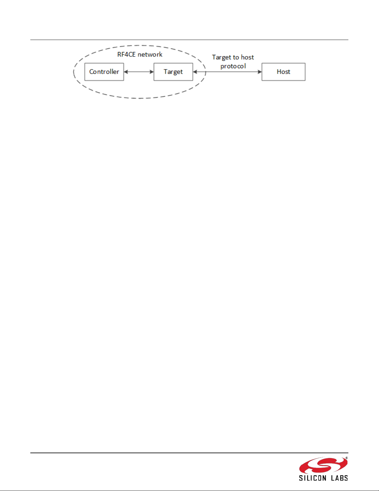
2 Remote Control Reference Design Overview
The Silicon Labs ZRC reference designs implement the followi ng t opology (Figure 2):
• Controller: This is the hand-held wirel ess rem ote control device
• Target: This devic e c ommunicates wirelessly with the Controller over the RF4CE network
• Host: This device communicates with the Target over a wired serial connection using the target-to-host
protocol described in this document.
Rev. 0.1 3
Page 4
AN906
Figure 2. RF4CE Remote Control System Topology
The Host is usually the main pr oc essor in a set-top box or other RF4CE-compliant equipment. In t his setting the
Target device is the embedded processor insi de the set-top box. For the Silicon Labs remot e contr ol reference
designs the Host devic e is a PC. T he Target device is a USB dongle or development kit that communic ates with the
Host via a serial connection or USB. As the target-to-host protocol is implemented in the Target firmware using a
UART or USB CDC connection, the target firmware can easily be reused in designs where the Target is embedded
in a set-top box.
The Silicon Labs RF4CE ZRC Full Feat ur ed Controller and Low Cost Controll er support t he f ollowing features:
• Key matrix scanning
• ZRC 2.0 action commands sent ov er RF4CE when buttons are pushed
• Infrared LED for cont r olling legacy equipment
• Power button LED (dual c olor on Low Cost Controller and single color on Full Feat ur ed Controller)
• Over-the-air action mapping to set actions for keys to user-defined ZRC2.0 action c ommands and/or IR
codes
• Over-the-air identify message to l oc ate Controller via blinking LED
In addition, the Full Featured Controller includes the following features:
• Buzzer to provide audio feedback
• Backlight LEDs for key matrix
• Accelerometer to turn on Backlight when controller is moved
• Streaming voice audio to Target (and Host) when Voice button is pushed
• Over-the-air identify message to locate Controller via buzzer sound
3 Controller Implementation
Firmware examples for the EM341 RF SoC in the Low Cost and Full Featured Controller s are included as RF4CE
sample applic ations in the EmberZNet stack release.
3.1 Devices
Both of the remote contr ols support for two devices, called TV and STB . T he dev ic es are sel ec ted using the TV and
the STB buttons on the controllers. The controller firmware is configured to support pai ri ng with up to two targets
that can be mapped to the STB or TV devices. The targets do not necessarily have to be a television and a set-top
box, even though t he text on the butt ons and t he dev ice names indicate this.
To pair a controller and target, first press the pairi ng butt on on the target (or host sending the Bind Request as
described in section 5.5.1.8) to allow a controller to pair with it. T hen, while holding down the PAIRING/SET key on
controller, press one of the device keys (TV or STB). The power button LED will be lit to indicate that a pairing is
ongoing. When the tar get acc epts the pairing, the LED will be turned off. If the c ontroller does not find a target to
pair with it will stop tryi ng after about 45 seconds and turn off the LED.
4 Rev. 0.1
Page 5

AN906
3.1.1 Pairing with Multiple Targets
When the controller is paired with two targets, the user first selects the target to communicate with by pressing the
associated devi c e butt on (TV or STB). W hen the user then pr es se s a key m apped to a specific ZRC 2.0 action
command, this command is sent to the target paired as the selected devic e.
The first target t hat is pair ed to a controller is paired as both the TV and STB device. When the second target is
paired, it is paired as the device corresponding to the button used in the pairing procedure.
3.1.2 Using the TV Device for IR Control
A common configuration is only to have one RF4CE-enabled device (e.g. set-top box) and a TV that only support s
legacy IR signals. In such a configuration, the set-top box can be used to program the action mappings on the
controller to allow it to send IR signals to the TV. In the referenc e firm ware, I R si gnals are only supported for the TV
device. Both the T V and the STB device must be paired with the set-top box target to allow the set-top-box to
update IR action mappings on the c ontroller.
3.2 Infrared Driver
The infrared driver incl uded in the reference firmware support s two IR dat abas e formats, the ZRC2.0 SIRD
(Standard Infr ar ed Database) format and the UIRD (Universal Infrared Descriptor) format (both regular and
encrypted). The IR codes can be transferred to the controller as acti on m apping updates matching the mappabl e
actions that the controller supports. As SIRD codes are native to the ZRC2.0, this format is expected for IR
descriptors unless a vendor ID is provided. For the UIRD codes the following dummy vendor IDs are used:
• 0x01: Regular UI RD
• 0x02: Encrypt ed UIRD
Note that the 32-bit encr y ption key must be obtained from the UIRD database prov ider and applied as a hashdefine call ed UIRD_DECRY P TI ON_KEY. The encryption UIRD encryption algorithm is not available as source
code, only as a pre-compiled library.
3.3 Accelerometer Motion Detection
The Full Featured Contr oller includes a 3-axis accel er om eter that is used to detect motion in any direction. The
acceleromet er is programmed over I2C to sample the 3-axis acceler ation data every 50 ms and set the interrupt
output to the EM341 if the accelerati on ex c eeds the c onfigured threshold. Aft er receiv ing an accelerometer interrupt
output, the EM341 will t ur n on the eight key pad backlight LEDs and keep them on until the cont r oller has been still
for at least 5 seconds.
3.4 Voice Compression and Streaming
The Full Featured Contr oller includes a digital PDM (pulse density modulation) microphone to record voice audio
through an audio i nlet at the t op of the remote, between the POWER and SET buttons. The voic e system is
designed for speech recognition to enable voice control of the host from the controller.
The digital PDM micr ophone c onv er ts the audio input to a 1-bit digital output in P DM format. In PDM format, the
density of digital ones i nc r ease s or decr ease s with increased or decreased audio pressure into t he mi c r ophone.
Since PDM is a digital f ormat, the microphone can be placed a reasonable distance from the hardware codec
without impacting the audio performance, which might occur wit h an analog microphone.
The Full Featured Contr oller is implemented in two ver sions. The first uses a hardware codec for processing the
microphone audi o before it is received by the EM341. The second does all of the audio processing internall y to the
EM341. The software audi o c odec has the lowest B OM cost, but uses more EM341 CPU cycles than the hardware
audio codec. The EM34X-VRDK inc ludes the hardware codec solution. For information on how to obtain the
software codec, see www.silabs.com/zrctraining
.
Rev. 0.1 5
Page 6
AN906
Bytes
Contents
7:1 (7 bytes)
MS ADPCM compressor state var iable
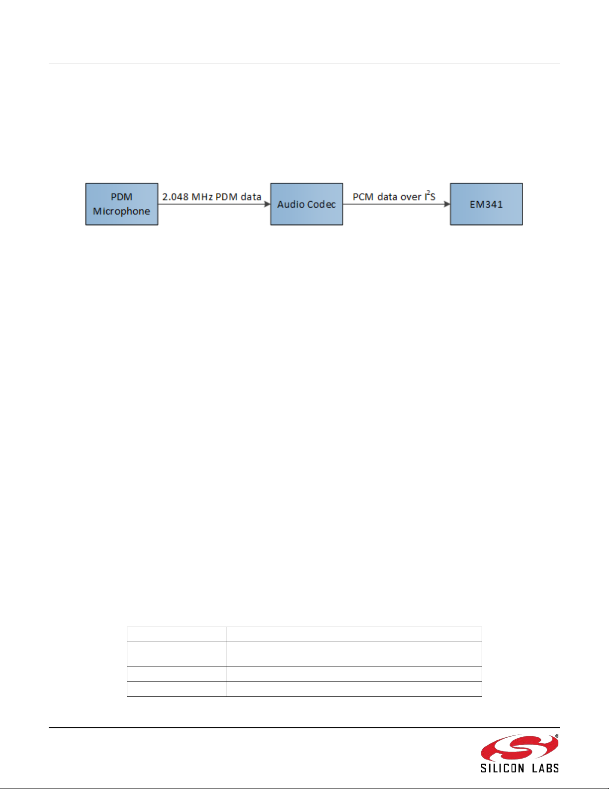
3.4.1 Hardware Audio Codec
The PDM 1-bit data stream is converted to a 16-bit PCM (pulse code modulation) by passing the PDM data through
a decimation filter . To remove the microphone’s DC component , t he c odec ’s 1st order I IR filter is also configured as
a high-pass filt er. To compensate the audio frequency response for artifacts induced by implemented plastics and
audio waveguide, the codec ’s multiple IIR bi-quads can be configur ed as an equal izer. In the Full Featured
Controller firmware, the codec’s IIR bi-quads are not enabled.
Figure 3 shows an overv iew of t he v oic e front -end.
Figure 3. Controller Hard Codec Voice Front -End
When the key matrix driver detects that the VOICE button is pressed, the audio streaming is set up by the following
steps:
1. Key m atrix shared GPIOs are reconfigur ed for the hardware audio codec.
2. Hardwar e audio codec is powered up by asserti ng a GPIO.
3. Timer 2 (TIM2) is conf igured to drive the master clock to the hardware audio codec .
4. Ser ial Controller 1 (SC1) i s confi gur ed as an SPI slave to accept I2S mono audio.
5. Ser ial Controller 0 (SC0), alr eady in I 2C mode, is used to confi gur e the hardware codec.
• Set up codec’s PLL and clock tree
• Enable digit al P DM micr ophone oper ation
• Set up decimation and digital filters
• Set digital gain
• Enable 16-bit (PCM) I 2S mono voic e audio data output @ 16 kSample/s.
6. T he filtered PDM to PCM I2S captured data is compressed and streamed to the paired target by the
controller.
The controll er will c ontinue streaming voice data to the target that is paired with the current dev ic e sel ection (TV or
STB) as long as the VOICE button is held down. The t arget dev ice receives the voice data and relays this to the
host. When the VOI CE button is released:
1. T imer 2 (TIM2) is reset.
2. Key m atrix shared GPIOs are reconfigur ed for the key matrix.
3. Hardwar e audio codec is powered down by de-asserti ng a GPIO.
ZigBee (and RF4CE) has a max bitrate of 250 kbps. However, due to overhead and real-world RF interference, the
highest practical sustained throughput with the EmberZNet stack is about 80 kbps. The v oic e audio is recorded as
16-bit samples @ 16 kSamples/s, which gives a bit rate of 256 kbps. To fit the audio within the allowed bit rate over
ZigBee, a 4:1 MS ADPCM compression is appl ied, resulting in 64 kbps compressed voice data. The 64 kbps
compressed voi c e data is then sent over RF4CE using a vendor-specific prof ile. This profile allows a voice payload
of 103 bytes to be sent with each m essage. The payload consists of the following el em ents:
0
102 :8 (95 byt es) Comp ress ed audio
6 Rev. 0.1
Message sequence number (i ncrea sed f or each mess age up
to 127 before wrapping to 0)
Page 7

AN906
The compressor state var iable contains 2 uncompressed 16-bit audio samples. Together with the 95 bytes of
compressed audio (2 samples per byte), a total of 192 PCM samples are transmitted with each message. To keep
up with the continuous 16 kSamples/s audio stream, a com pr essed audio message is sent every 12 ms from the
controller to the target. For details on the micr ophone driver implementation, see the comments at the beginning of
the driver source code.
Using the MS ADPCM compressor state contained in each audio message, the target (or Host) decompresses t he
compressed audio stream to 16-bit PCM audio data @ 16 kSamples/s. The PCM audio data is then sent to t he
speech recogniti on engine, implemented in the host or via Cl oud. The PCM audi o quality far exceeds the
performanc e requi r ed by l eading speech rec ognition engines.
3.4.2 Software Audio Codec
The PDM 1-bit data stream is converted to a 16-bit pulse code modulation (PCM) by passing the PDM data through
a decimation filter implemented in software. To remove the microphone’s dc component, a 1st order II R filt er
implements a high-pass fi lter. To compensate the audio frequency r esponse for artifacts induced by im plem ented
plastics and audio waveguide, four user configurable IIR bi-quads can be configured as an equaliz er . In the Full
Featured Controller firmware, the software codec’s II R bi-quads are not enabled.
Figure 4 shows an overview of t he software audio codec voice front-end.
Figure 4. Controller Soft Codec Voice Fro nt-End
When the key matrix driver detects that the VOICE button is pressed, the audio streaming is set up by the following
steps:
1. Key m atrix shared GPIOs are reconfigur ed for the software audio codec.
2. Software audio codec is powered up by asserting a GPIO.
3. Ser ial Controller 1 (SC1) i s confi gur ed as a SPI master to acc ept PDM mono audio into DMA buffers.
4. When a DMA buffer is filled, the sof tware codec processes the buffer’s 1-bit/1.2 MSps PDM data into 16bit/16 kSps PCM data by:
• Applying decimation filter
• Applying user configurable four IIR equalization biquads
• Applying high-pass filter to remove dc component
• Applying digital gain to achieve -12 dBFS at 94 dBSPL
5. T he filtered PDM to PCM captured data is compressed and streamed to the paired target by the contr oller.
The controll er will c ontinue streaming voice data to the target t hat is pai r ed with the current device selection (TV or
STB) as long as the VOICE button is held down. T he target device receives the v oic e data and relay s this to the
host. When the VOICE button is released:
1. Ser ial Controller 1 (SC1) is reset.
2. Key m atrix shared GPIOs are reconfigur ed for the key matrix.
3. Software audio codec is powered down by de-asserting a GPIO.
ZigBee (and RF4CE) has a max bitrate of 250 kbps. However, due to overhead and real-world RF interference, the
highest practical sustained throughput with the EmberZNet stack is about 80 kbps. The v oic e audio is recorded as
16-bit samples @ 16 kSamples/s, which gives a bit rate of 256 kbps. To fit the audio within the allowed bit rate over
Rev. 0.1 7
Page 8

AN906
ZigBee, a 4:1 IMA ADPCM compression is applied, resulting in 64 kbps compressed v oic e data. The 64 kbps
compressed voi c e data is then sent over RF4CE using a vendor-specific prof ile. This profile allows a voic e payl oad
of 104 bytes to be sent with eac h m essage. The pay load consists of the following elements:
Bytes Contents
0
3:1 (3 bytes) IMA ADPCM compr essor state variabl e
103:4 (100 bytes) Com pres sed audio
With the 100 bytes of compressed audio (2 samples per byte), a total of 200 PCM samples are tr ansmit ted with
each message. To keep up with the continuous 16 kSamples/s audio stream , a com pr essed audio message is sent
every 12.5 ms from the controller to the target.
Using the IMA ADPCM compressor state contained in each audio message, the target (or Host) decompresses the
compressed audio stream to 16-bit PCM audio data @ 16 kSamples/s. The PCM audio data is then sent to the
speech recogniti on engine, implemented in the host or via Cl oud. The PCM audi o quality far exceeds the
performanc e requi r ed by l eading speech rec ognition engines.
3.5 Key Matrix Driver
The key matrix driver i n the reference firmware is set up to scan a 7x7 key matrix, connec ted to 14 GPIO pins (7
row pins and 7 column pins). Howev er , it c an be configur ed to fit other keyboard lay outs. An example 4x4 key
matrix is shown in Figure 5.
Message sequence number (i ncrea sed f or each mess age up
to 127 before wrapping to 0)
Figure 5. Example 4x4 Key Matrix
In Deep Sleep mode all the columns are configured as inputs with internal pull-down resistors enabled. The
columns’ GPIO pins are al so set up to wake up the devi c e when it det ec ts a change in the logic input value of the
pin. The rows are all configured to be high output push-pull. When a key is pressed, the row pin dr ives the
associated col um n pin high through the closed circuit and the device wakes up because of the input pin change.
8 Rev. 0.1
Page 9

AN906
3.5.1 Key Detection
When the device wakes up, the driver is then called to figure out which key was pressed. This is done by tri-stating
all row pins except for the one that is being driven high. Then t he stat e of each of t he col um ns is recorded, before
the process is repeated wit h the next row being driven high. At the end of this process the driver has recorded all
buttons that were pressed during the scan. The application can later read out the latest recorded k ey states and
perform the appropri ate actions based on them. When no key presses are detected, the GPIOs are set in their
sleep configuration before the device enters Deep Sl eep. I n this example the rows are used as outputs and driven
high, but both the drive direction and active level can be configured with defines.
Note that the Low Cost Controller and Full Featured Controller har dware do not include any reverse flow protect ion
diodes for the switches. As such, ghosting (i.e., an incorrect key detection) can occur if more than two keys are
pressed simultaneously. The key matrix driver would, however, be compatible with hardware designs that include
diodes for full N-key r ollov er support .
3.5.2 Pin Sharing
For both of the controller designs, the full 7x7 key matrix uses 14 GPO pins. To m aximize functionality with the
available GPIO pins, the key matrix pins are shared with other func tions. For both controller desi gns, the debug
header shares pins with t he k ey mat rix and, on the Full Featured Controller, the audio front-end control also share s
pins.
Some of the debug pins are re-used as row and column pins. To support debugging, the key matrix driver checks if
the device is in a debug session duri ng the initialization and skips the key scanning for any columns or rows that
are used as debug pins. This means that some keys will not work when a debug adapter is attached. When the
device is disconnected from the adapter and power-cycled, all pins will function normally again. The masks for the
debug pins are set in the board header file.
For the Full Featur ed Controller, key matrix GPIO pins are also used to support the audio front-end, both f or the
soft and hard audi o codec solutions. The VOICE button is intentionally placed on a row and column that are not
shared with the audio front-end. When VOICE butt on is pressed, the GPIOs used for the audio front-end are
reconfigured for the audio interface and remain in that configurati on dur ing audio streaming. The VOICE button is
constantly monitored and, when released, the audio streaming is stopped and the GPIOs used for the audio frontend are reconfi gur ed for the key matrix.
3.6 Identification Message
To locate a misplaced c ontroller, the target can send it an identification message. When the controller receives this
message it will beep the buzz er and blink the backlight LED 5 times, hopefully allowing the user to find it.
3.7 Action Mapping
The controller reference firmware is set up to associate a def ault RF4CE ZRC2.0 action command or an IR
command for each button on the rem ote. Using ZRC2.0 action mappings, t he c ontroller can be programmed by the
target to perform new actions when a key is pressed. In the controller r eference firmware, most of the butt ons on
the controll er are configured as a mappable action. The list of the support ed m appable actions can be seen (and
modified) in the RF4CE tab for your RF4CE project in Ember Desktop.
Action mappings are selected with the demo PC application and sent to the target. The target t hen waits for an
incoming heartbeat notification from any of the contr ollers it is pai r ed with. When a heartbeat is received, the target
sends the new action mappings to the controller.
3.8 Storage
The remote control fi rmware stores the pairing inf ormation in simulated EEPROM using tokens. Thi s all ows the
controller to rem em ber its pair ed dev ices through a power cycle.
Rev. 0.1 9
Page 10

AN906
Any programmed acti on m appings are stored in RAM and are lost duri ng a power cycl e. T o regai n the action
mappings automatically, the controller r equests act ion mappings from all paired targets after it powers up. This
allows changing batt er ies on the controller wit hout having to re-pair with the target( s) or r e-pr ogr am the action
mappings manuall y .
Statically-allocated tables are used to store the action mappings for the mappabl e actions supported by the
controller. If the action mappings include vari able-length data like IR descript or s, the variable-length data i s stored
in a RAM heap memory. The amount of RAM alloc ated for the action mapping heap is by default 1300 byt es and
can be configured in the Zi gB ee Rem ote Control 2.0 Action Mapping Client pl ugin settings in Ember Desktop.
3.9 Power Consumption
The controll er firmware is set up to enter Deep Sleep mode whenever no butt ons are pr essed. In t his mode the
controller c onsumes approximately 1.5 µA. The Full Featured Controller includes an accelerometer that measures
movement every 50 ms and turns on the but ton backlight for 5 seconds if motion is detected. During Deep Sleep
mode the acceler om eter adds on average 5.5 µA.
The controll er and tar get implement an asymmetric protocol where the target can only send data to the controller
immediately following a heartbeat notification sent out by the controller. The controller, on the other hand, can send
data to the target at any time. T his i s done to allow the controller to keep its RF receiver disabled and go to Deep
Sleep as much as possible t o conserv e battery life. In a resting scenario where no RF4CE c ommunication is done
by the applicati on ( k ey presses, act ion mapping updates etc.) the only time the controller is awake is to send
periodic heartbeat notifications to t he target and listen for a response for a while before it goes to sleep. By default
the controll er firmware is set up to send a heartbeat to every paired target every 5 seconds. The energy consum ed
by the controller duri ng a hear tbeat cycle (with no response fr om the t ar get) is about 1.5 mJ (@3 V). This equates
to an added average consumption of 100 µA for each paired target wit h the default 5-second heartbeat interval.
Increasing the heartbeat interval can theref or e save power, but at the expense of longer worst-case latenc y when
the target wants to start communication with the controller (e.g. when programming action mappings and sending
identification messages).
4 Target Im plement a ti on
The EmberZnet stack r elease i nc ludes an RF4CE sample application c alled Full Featured Target that supports both
the Low Cost Controller and the Full Featured Controller. See UG113, EM34x Development Kit User’s Guide, for
instructions on how to create a new application based on this.
The Full Featured Tar get sam ple application can be confi gur ed to run on the following target devices:
• EM346 breakout board in the EM34x Development Kit. With this setup the serial connec tion to the PC is
done either over USB-CDC or the RS-232 por t on t he breakout boar d.
• EM3588 Telegesis USB stic k . T his device implements a USB Communication Devic e Class (CDC) which
is used to communicate wit h the PC.
Both targets have a button for allowing incoming pairing requests. In the EM34x Development Kit, BUTTON1 is
used for this. Bot h targets also support pairing requests f r om a host sending t he B ind Request as described in
Section 5.5.1.8, Bind Request
The target can be pair ed with up t o five c ontrollers. If a pairing attem pt is m ade when the pairing table is full the
pairing tabl e is erased and the new pairing is added.
Two s tatically-allocated tables are used to store data, one for the mappable actions that ar e read fr om the paired
controllers, and the other for storing the action mappings to remap the mappable actions. T he si z e of bot h tables is
set to 50 bytes for the EM346 breakout board and 100 bytes for the EM3588 USB stick. If the action mappings
include vari able length data like IR descriptors, this is stored in a RAM heap memory. The amount of RAM
allocated for the action mapping heap is by default 700 bytes for the EM346 and 4000 bytes for the EM3588. The
10 Rev. 0.1
.
Page 11

AN906
size for the mappable actions, remap table, and the heap memory can be confi gur ed in the Zi gB ee Rem ote Control
2.0 Action Mapping Server plugin settings in Ember Desktop.
5 Target-to-Host Protocol
The ZigBee Remote Control pr ofile, ZRC, specifies the communication between the ZRC Originator and Reci pient ,
which are the Controller and Target in this case. However, it does not specify how the communication should be
utilized at the application level. The Target-to-Host Protocol (THP ) defines how required informati on is
communicat ed between the appl ication at the Target and the Host computers in the system.
This specification assumes that the THP will be transport ed over a full duplex serial interface. It can be transported
over eit her a UART interface or a USB port implementing a CDC (Comm unic ation Device Class) that emulat es a
UART.
5.1 Protocol Layers
The OSI Model (Open Systems Interc onnec tion Basic Reference Model) is an abstract description for layered
communicati ons and computer network protocol design. The OSI Model divides network archit ec ture into seven
layers which, fr om top to bot tom, are the Application, Presentation, S ession, Transport, Network, Data-Link, and
Physical Layer s.
The RF4CE remote control t ar get application and the host computer use a set of prot oc ols to send their data down
the layers, encapsul ating the data at each level. The THP consists of two layers in t he OSI Model: t he application
layer and the presentation layer. The session/tr ansport layers are represented by the seri al communication.
Figure 6. Protocol Layers
The Applicati on header and data are a message in the application layer . T he pr esentation layer prefix, data and
postfix are a messages in the presentation layer. The data part of t he lay er is called the payload.
The RF4CE target will be connec ted to the host computer using the layers shown in Figure 7.
Figure 7. Communication Layers
Rev. 0.1 11
Page 12

AN906
5.2 Protocol Operation
The protocol operation at the application layer between the Target and Host is connectionless. A message is sent,
and a response may be sent back depending on the Message id.
Unless otherwise stated, the protocol assumes that all communication requests are started by the target and sent
to the host computer. The host com puter cannot send anything to the target without first being asked to do so. In
order to let the host make t he target aware that it has information for it, the target should regularly poll t he host for
status. The host may reply with a Check Condition status and one of the “ att ention” codes in the “Conditi onal”
field. When the condi tion has been read, it may be reset by the host if it no longer applies. One example is the
reset/power on that normally will be read only once, unless the host is reset during operati on.
5.3 Presentation Layer
The presentation lay er ensures that a star t of a message can be found. Numbers with prefix “0x ” below are given in
hexadecim al notati on.
5.3.1 Message Format
The message format for the presentation layer is shown below:
StartFrame Payload Checksum EndFrame
The StartFram e and EndFr am e are the Presentat ion Prefix and Presentation Postfix respectively.
Field des c r iption:
Size Range/Value Name Description
1 0xC0 StartFrame
0..n Payload The payload.
1 Checksum 8-bit checksum.
1 0xC1 EndFrame
The s tart f rame unique
identifier.
The end frame unique
identifier.
5.3.2 Framing
Each message begins with the byte 0xC0 and ends with the byte 0xC1. In between the fr ami ng by tes are the
payload and the check sum.
5.3.3 Checksum
The last byte of a message (without the framing) contains an 8-bit checksum. The checksum is calculated over the
entire message, without framing and without including the checksum byte. The checksum is obtained by XORing
one and one byte.
5.3.4 Escaping
To make sure that 0xC0 and 0xC1 are not cont ained within the payload an escape sequence is used. The value
0x7E is used to XOR the following byte with the value 0x20. This is used for the following three combinations:
• 0x7E 0x5E is used for 0x 7E
• 0x7E 0xE0 is used for 0xC0
• 0x7E 0xE1 is used for 0xC1
12 Rev. 0.1
Page 13

AN906
Size
Range/Value
Name
Description
5.3.5 Example
The “0x” prefix is omitted for readability in the example below.
• Payload: 00 C0 05
• Add checksum:00 C0 05 C5
• Add escaping: 00 7E E0 05 C5
• Add framing: C0 00 7E E0 05 C5 C1
Note that the 0xC0 of the payload is replaced with the 0x7E 0xE0 escaping sequence.
5.4 Application Layer
The THP is defined as v ari able length packets that are transferr ed between the Target and the Host.
5.4.1 Message Format
The message format for the application layer is shown below:
Application Header App l ication Data
The Applicati on Header is mandat or y . Some messages may consist of an applicati on header only. The Application
Data is the payload of the application layer message.
Application Header f ormat
Size Range/Value Name Description
1 0 Version Version of the message format.
1 See 5.5.2 Message I d Message t ype i dentifier. Each message typ e
has a uniq ue mes sage i d.
1 [0,255] Data Length The length of the Application Data.
Application Data format
0..101 App l ication Data Payload of the message.
5.5 Application Layer Messages Defined
The application m essage f ormat is defined in section 5.4, Applic a t io n La y e r , and is used for all messages that are
transported between the target and the host. Because some of the payloads may be used for more than one
Message Id, the payloads are defined first. Next the different M essage I d’s are defined.
Messages can be sent either way and this document the following not ation is used:
Requests: Mes sage s goi ng from the target to the host.
Acknowledges: Messages going from the host t o the target.
5.5.1 Message Payload
The following sections defines the different payl oads. P lease refer to section 5.5.2, Message Id, to find which
messages are using the different payloads.
Rev. 0.1 13
Page 14

AN906
Size
Range/Value
Name
Description
1 Conditional
The value reported when the Status is Check
5.5.1.1 Get Status
Request status fr om the host.
Status – request
Size Range/Value Name Description
1 0 VersionMajor Target protocol version major number.
1 0 VersionMinor Target protocol version minor number.
0..1 Status S tatus fro m the target to the host. The target
0..1 Conditional
Status - acknowledge
1 0 VersionMajor Host protocol version major number.
1 0 VersionMinor Host protocol version minor number.
1 Status The host status.
Status de finitio ns
Status Description
0 Status OK
1 Check Condition
2 Busy
may notify the host by adding the Status and
Conditional fields.
Condition.
Conditional definitions
Conditional Description
0 Condition OK
1 Undefined
10 Not ready
20 Hardware error
30 Illegal request
40 The device h as been reset or off
41 Action mappings have changed
42 I dent i fy contr oller
14 Rev. 0.1
Page 15

AN906
Size
Range/Value
Name
Description
Size
Range/Value
Name
Description
5.5.1.2 Action
Whenever a key is pressed on the controller, and the key is mapped to an RF-action, the target will r ec eive the
corresponding action code. The target forwards the code t o the host by using this Action package.
Action – request
1 ActionType
1 ActionModifier
1 ActionBank
1 ActionCode
2 VendorId
Action – acknowledge
No acknowledge.
5.5.1.3 Action Mapping
The target may at any tim e request acti on m appings from the host, but a sequence is typically initiated by the host
signaling t he target that new mappings are available by repl yi ng with Status=Check Condition and
Conditional=Action mappings have changed.
One action mappi ng can be requested at a time. Reading all action mappings from the host will require repeated
requests. The action mapping message sequence is shown in Figure 8.
Figure 8. Request Action Mappings Message Sequence Chart
Action Mapping – request
1 Device Type
1 Bank
1 Action The action code to map from.
Rev. 0.1 15
Page 16

AN906
1 RF Data Length
The number of RF data bytes that are included
Size
Range/Value
Name
Description
Size
Range/Value
Name
Description
Size
Range/Value
Name
Description
Action Mapping - acknowledge
Size Range/Value Name Description
1 Device Type
1 Bank
1 [0x00, 0x7f] Action The action code to map from.
1 MappingFlags
1 IR Data Length The number of IR data bytes that are included
0..m RF Data If p resen t, th e RF data.
0..n IR Data If present, the IR data.
RF data format
1 Config
1 Option
3 RF action
in this message.
in this message.
mapping data
RF action mapping data format
Size Range/Value Name Description
1 Not used
1 Bank
1 Action code
IR action data format
1 Config
2 Vendor
n IR action mapping
data
IR action mapping data according to the format
defined by the application.
IR action mapping data format
One actual form at can be the one defi ned in the ZigBee RF4CE: ZRC Profile Specificati on V er si on 2.0, Annex B:
Standard IR Database format, but other formats can be used as long as the host and controller agrees.
5.5.1.4 Audio data
Send compressed audio data (from target to host).
Audio data – request
101 Audio Data The audio data as received from the controller
16 Rev. 0.1
to the target.
Page 17

AN906
Size
Range/Value
Name
Description
1 Pairing Index
The pairing index for the heartbeat.
Audio data – acknowledge
No acknowledge.
5.5.1.5 Heartbeat
This is a message that is send f or every hear tbeat the target receives from the contr oller.
Heartbeat – request
1 Triggers Additional triggers for the heartbeat.
Heartbeat – acknowledge
No acknowledge.
5.5.1.6 Identify
The target can signal that the controller should blink and beep for a defined period. T his is normally initi ated by the
host signaling t he target that an Identify is in progress by setting Status=Check Condition and
Conditional=Identify controller. The Identify message sequence is shown in Figure 9.
Figure 9. Identify Controller Message Sequence chart
Identify – request
No parameters.
Identify – acknowledge
Size Range/Value Name Description
1 Flags Identify flags, according to RF4CE:
0x01 = stop on action
0x02 = flash light
0x04 = sound
0x08 = vibrate (not supported by HW)
1 Time The time in seconds the controller shall
perform the identification.
Rev. 0.1 17
Page 18

AN906
Size
Range/Value
Name
Description
Id
Name
Payload in section
Action
14
Action Mapping Req
5.5.1.3 Action Mapping
Bind Information
5.5.1.7 Bind Information
This is a m essage sent f r om the t ar get t o the host computer when there is an event related to a bind pr oc ess on the
target.
Bind Information – request
1 See table below. Bind I nfo A byte des cribin g the bind event.
Bind Info definitions
Value Name Description
0 Init A binding is requested by either pushing the button or a Bind
Request is sent to the target.
1 Success The bind operation was successful.
2 Failure The bind operation failed.
3 Attempt A co ntrol ler has initiated a bind o peration .
4 Proxy
Bind Information – acknowledge
No acknowledge.
5.5.1.8 Bind Request
This is a message that can be sent fr om the host c om puter to the target to initiate a bind on the tar get. On som e
targets this operat ion can be done by pressing the bind button, but on ot her s no button is available. Sending a bind
request message is identical to pushing the bind button on t he target.
Bind Request – request
No request.
Bind Request – acknowledge
No parameters.
5.5.2 Message Id
The Message Id is described in the following table:
0 Get Status Req 5.5.1.1 Get Status
1 Get Status Ack 5.5.1.1 Get Status
10 Act io n Req 5.5.1.2
15 Action Mapping Ack 5.5.1.3 Action Mapping
20 Audio Data Req 5.5.1.4 A udio data
30 Hea rtbeat R eq 5.5.1.5 Heartbeat
40 Identify Req 5.5.1.6 Identify
41 Identify Ack 5.5.1.6 Identify
50 Bind Info Req 5.5.1.7
53 Bind Request Ack 5.5.1.8 Bind Request
18 Rev. 0.1
Page 19

AN906
CONTACT INFORMATION
Silicon Laboratories Inc.
400 West Cesar Chavez
Austin, TX 78701
Tel: 1+(512) 416-8500
Fax: 1+(512) 416-9669
Toll Free: 1+(877) 444-3032
For additional information please visit the Silicon Labs Technical Support page: http://www.silabs.com/support/
Patent Notice
Silicon Labs invests in research and development to help our customers differentiate in the market with innovative low-power, small size,
analog-intens i ve mi xed -signal solutions. Silicon Labs' extensive patent portfolio is a test am ent to our uniq u e approach and w orl d-class
engin eering team.
The information in this document is believed to be accurate in all respects at the time of publication but is subject to change with out n otice.
Silicon Laboratories assumes no responsibility for errors and omissions, and disclaims responsibility for any consequences resulting from the
use of information included herein. Additionally, Silicon Laboratories assumes no responsibility for the functioning of undescribed features or
parameters. Silicon Laboratories reserves the right to make changes without further notice. Silicon Laboratories mak es n o w arr an t y,
represen tation or gu arantee r eg arding the suitability of its produc ts f or any p art ic u l ar purp ose, nor d oes Silicon Lab oratories ass u m e an y liability
arising ou t of th e app lication or use of any produc t or circ ui t , an d sp e c ifically dis c laims any an d all li ab i l it y, inc luding without limitation
conseq u ent i al or inc id ental damag es . Silic on L ab or at or i es products are not design ed, int en ded, or authorized for use in applications intended to
support or s us t ain life, or for any other app lication in which the failure of the Silicon Lab oratories pr oduc t c ould creat e a sit u ation wher e per sonal
injury or death may occ ur. Should Buy er purc h ase or use Sil icon Laboratories products for any such uni nt ended or un aut h or i z ed application,
Buyer shall indemnify and hold Silicon Laboratories harmless against all claims and damages.
Silicon L ab oratori es, Silicon Labs, and Ember are registered trademarks of Si licon Lab oratories Inc.
Other products or br an dn am es m entioned herein ar e tr ad em ar ks or regis tered tr ademarks of t h eir respective hold ers .
Rev. 0.1 19
 Loading...