

Page 1

M88 Evaluation Kit
USER GUIDE
STO-DEV7227-HB REV. 2.1
© 2019 Silicon Labs, Inc. All Rights Reserved.
Page 2

M88 Evaluation Kit User Guide Revision History
Document: STO-DEV7227-HB M88 Evaluation Kit User Guide
Rev
Date
Comment
1.0
2016-10-17
Included in FW release v1.0.0
1.1
2016-11-11
Included in FW release v1.0.1 and v1.0.2
1.2
2016-12-09
1.3
2017-02-16
Included in FW release v1.0.6
1.4
2017-03-07
Included in FW release v1.0.7
1.5
2017-04-20
Included in FW release v1.0.8
1.6
2017-07-18
Included in FW release v1.0.9
2.0
2019-06-04
Released with new Eval Kit model
2.1
2019-12-12
Included in FW release v1.0.19
Changes in Rev 2.1
Section
Changes since previous revision
7
Table 1. PPS out is 50 Ω
9.1
Pull-up is available on UTX and not on URX
10
Clarified jumper positions
Changes in Rev 2.0
Section
Changes since previous revision
All
New document template
All
Removed references to enclosure as board is now delivered without
11
Added description on usage of GNSS add-on board
13
Added application examples
17
Added descriptions on how to update FW
Changes in Rev 1.6
Section
Changes since previous revision
10
Corrected jumper selection for P308
Changes in Rev 1.5
Section
Changes since previous revision
9
Added information on pin 1 for the Trace Adapter.
18
Added picture on how to connect Trace Adapter.
Changes in Rev 1.4
Section
Changes since previous revision
12
Added picture of oscillator add-on board.
Changes in Rev 1.3
Section
Changes since previous revision
10
P402 and P401 were switched
8, 9, 10
Sorted out confusion with respect to COM port numbers.
7, 8
Clarification on which connector to use for single ended.
Revision History
STO-DEV7227-HB Rev. 2.1 2
Page 3

M88 Evaluation Kit User Guide Revision History
16
Rewrote first section for clarity.
9.1
Added pin descriptions to on-board connectors
Changes in Rev 1.2
Section
Changes since previous revision
10
Removed restrictions in previous FW version.
12.1
Added values for which voltage control range to use.
STO-DEV7227-HB Rev. 2.1 3
Page 4

M88 Evaluation Kit User Guide Table of Contents
Table of Contents
1 About this Document ............................................................................................................................ 7
2 Scope ..................................................................................................................................................... 7
3 General Description .............................................................................................................................. 7
4 Before you begin ................................................................................................................................... 8
5 Power .................................................................................................................................................... 8
6 Block diagram ........................................................................................................................................ 8
7 Front side connectors ......................................................................................................................... 10
8 Back side connectors........................................................................................................................... 11
9 Additional connectors ......................................................................................................................... 12
9.1 Connector pin descriptions ......................................................................................................... 13
10 Jumpers ........................................................................................................................................... 16
10.1 Inputs .......................................................................................................................................... 17
10.2 Reference .................................................................................................................................... 18
10.3 Outputs ....................................................................................................................................... 19
10.4 COM, TOD, PPS............................................................................................................................ 19
11 Add-on boards................................................................................................................................. 20
11.1 Oscillator board ........................................................................................................................... 20
11.1 GNSS board ................................................................................................................................. 20
11.2 Enabling the GNSS LED ................................................................................................................ 21
11.3 Check GNSS reception on the M88 ............................................................................................. 21
12 Connecting to the board ................................................................................................................. 21
13 Application examples ...................................................................................................................... 21
13.1 Set up the M88 Evaluation Kit as a E2E, Multicast PTP slave ..................................................... 21
13.2 Set up the M88 Evaluation Kit as a E2E, Unicast PTP slave ........................................................ 22
14 Using the PTP engine ...................................................................................................................... 24
15 Using the PLL ................................................................................................................................... 25
15.1 Configuration .............................................................................................................................. 25
15.2 Loading ........................................................................................................................................ 25
15.3 Controlling ................................................................................................................................... 25
16 Further configuration of the M88 Evaluation Kit ............................................................................ 25
17 Updating firmware on M88 Evaluation Kit ..................................................................................... 26
18 References ...................................................................................................................................... 26
STO-DEV7227-HB Rev. 2.1 4
Page 5

M88 Evaluation Kit User Guide List of Figures
List of Figures
Figure 1. M88 Evaluation Kit (without Oscillator and GNSS add-on boards)................................................ 7
Figure 2. M88 Evaluation Kit block diagram ................................................................................................. 9
Figure 3. M88 Evaluation Kit front side connector placement. .................................................................. 10
Figure 4. M88 Evaluation Kit back side connector placement. ................................................................... 11
Figure 5. M88 Evaluation Kit board-top connector placement. ................................................................. 12
Figure 6. M88 Evaluation Kit jumper placement overview......................................................................... 16
Figure 7. Input selection jumpers ............................................................................................................... 17
Figure 8. Reference selection jumpers – NB pin 1 position on P307 .......................................................... 18
Figure 9. Output selection jumpers ............................................................................................................ 19
Figure 10. COM, TOD and PPS selection jumpers ....................................................................................... 19
Figure 11. Oscillator add-on board ............................................................................................................. 20
Figure 12. GNSS add-on board .................................................................................................................... 20
STO-DEV7227-HB Rev. 2.1 5
Page 6

M88 Evaluation Kit User Guide List of Tables
List of Tables
Table 1. M88 Evaluation Kit front side connector descriptions. ................................................................. 10
Table 2. M88 Evaluation Kit back side connector description. ................................................................... 11
Table 3. M88 Evaluation Kit board-top connector description. ................................................................. 13
Table 4. COM2 connector pin description .................................................................................................. 13
Table 5. COM1 connector pin description .................................................................................................. 13
Table 6. CB Pro FP connector pin description ............................................................................................. 14
Table 7. SPI Master connector pin description ........................................................................................... 14
Table 8. SPI Slave connector pin description .............................................................................................. 14
Table 9. I/O Bus connector pin description ................................................................................................ 14
Table 10. PLL Control connector pin description ........................................................................................ 14
Table 11. GNSS Add-on Board System Connector pin description ............................................................. 15
Table 12. Oscillator Add-on Board System Connector pin description....................................................... 15
Table 13. M88 Evaluation Kit input selection jumpers - Grey options are default factory settings ........... 17
Table 14. M88 Evaluation Kit reference selection jumpers - Grey options are default factory settings.... 18
Table 15. M88 Evaluation Kit output selection jumpers - Grey options are default factory settings ........ 19
Table 16. M88 Evaluation Kit COM, TOD and PPS selection jumpers - Grey options are default factory
settings. ....................................................................................................................................................... 19
Table 17. Oscillator voltage control range .................................................................................................. 20
STO-DEV7227-HB Rev. 2.1 6
Page 7
M88 Evaluation Kit User Guide About this Document
1 About this Document
This document describes the use of the M88 Evaluation Kit. Its purpose is to help a user to set up the
board electrically and mechanically and how to communicate to it. It’s not a complete guide for all
functionality provided by the M88 module it’s carrying. For this we refer to [1].
2 Scope
This document covers the M88 Evaluation Kit Rev A carrying the M80 Rev B module and running M88
v1.0.19 FW and later. It also covers the oscillator add-on board that is mounted on the M88 Evaluation
Kit.
3 General Description
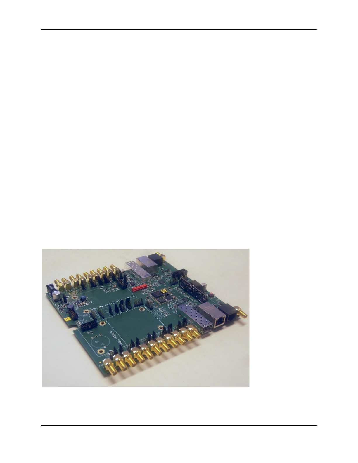
The M88 Evaluation Kit is an evaluation board for the M88 module. The board makes it possible to
control and monitor all functionality provided by the M88. The board is powered through a single 5V
power supply (included) or through Power-over-Ethernet. It provides two Ethernet interfaces for
communication to the network, including PTP. It has a USB port for serial communication, SMA
connectors and ITU-T G.703 V.11 compliant RJ45 for PPSIN, PPSOUT, TODIN and TODOUT plus multiple
SMA connectors for configurable input and output frequencies. It provides a debug interface that can
be used with Silicon Labs' Trace Adapter (not included) for communication with Silicon Labs' Developer
IDE and a SPI interface for programming of the Si5348 chip onboard the M88. It also provides several
jumpers for configuration.
The M88 Evaluation Kit also have two expansion slots intended for alternative oscillators and GNSS
receivers respectively.
Figure 1. M88 Evaluation Kit (without Oscillator and GNSS add-on boards)
STO-DEV7227-HB Rev. 2.1 7
Page 8

M88 Evaluation Kit User Guide Before you begin
4 Before you begin
You will need the following to use the board:
• Power supply 5V, 3A – included
• Ethernet cables (SFP and fiber if you intend to use optical communication) – not included
• SMA cables – not included
• USB cable – included
• GNSS antenna – not included
• A PC with a terminal program such as TeraTerm or PuTTy – not included
Optional devices in case you plan to write and debug your own SW for the M88 and/or configure the
Si5348 of the M88.
• Silicon Labs' Trace Adapter
• Silicon Labs Developer IDE
• SiLabs Trace Adapter
5 Power
The board only needs a single 5V supply and depending on what add-on boards that are used (some
OCXO can consume considerable amount of current when warming up) we recommend using a power
supply that can deliver 3A.
The board can also be powered by a PoE switch if connected to Port 1. This will supply adequate power
in most cases except for when a large OCXO is used on an add-on board. The M88 Evaluation Kit has
onboard regulators to provide all necessary voltages for the components on the M88 Evaluation Kit
including the M88. There is a green LED indicating 3.3V to the left of the board when seen from the
front panel and another LED indicating if power is supplied by PoE.
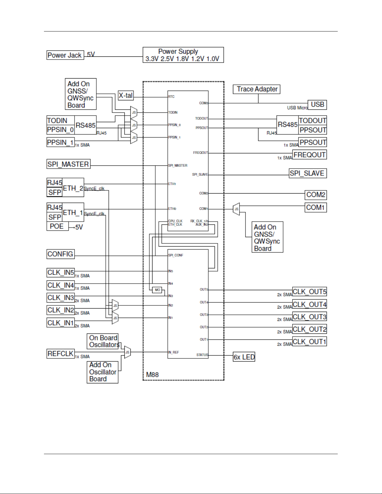
6 Block diagram
The block diagram below shows the connections the M88 Evaluation Kit and to some extent, for
improved understanding the connections on the M88 module itself. In the picture JS means jumper
select. See section 10.
STO-DEV7227-HB Rev. 2.1 8
Page 9
M88 Evaluation Kit User Guide Block diagram
Figure 2. M88 Evaluation Kit block diagram
STO-DEV7227-HB Rev. 2.1 9
Page 10

M88 Evaluation Kit User Guide Front side connectors
Name
Type
Description
FREQOUT
SMA female
Synthonized frequency selectable through SW 5/10/20/25 MHz
OUT1 -/+
SMA female
Configurable low jitter frequency output. Use + for single ended.
OUT2 -/+
SMA female
Configurable low jitter frequency output. Use + for single ended.
OUT3 -/+
SMA female
Configurable low jitter frequency output. Use + for single ended.
OUT4 -/+
SMA female
Configurable low jitter frequency output. Use + for single ended.
OUT5 -/+
SMA female
Configurable low jitter frequency output. Use + for single ended.
Port 1
RJ45 with
integrated LED
and SFP slot
Primary Gigabit Ethernet. Use either RJ45 or SFP. RJ45 supports
Power over Ethernet.
ToD/1PPS Out
RJ45
ToD and 1 PPS according to G.703 V.11. 1 PPS in RJ45 same signal
as 1 PPS Out on SMA.
PPS Out
SMA female
Configurable PPS, default 1PPS 100ms positive pulse. 50 Ω
Port 1
ToD/
1PPS
Out
7 Front side connectors
Figure 3. M88 Evaluation Kit front side connector placement.
Table 1. M88 Evaluation Kit front side connector descriptions.
STO-DEV7227-HB Rev. 2.1 10
Page 11

M88 Evaluation Kit User Guide Back side connectors
Name
Type
Description
5V DC
DC jack 5.5/2.5 mm
5V power supply, center plus. Current needed depends on
add-on boards.
IN5
SMA female
Frequency input, single ended.
IN4
SMA female
Frequency input, single ended.
IN3 +/-
SMA female
Frequency input, configurable as differential or single ended.
Use + for single ended.
IN2 +/-
SMA female
Frequency input, configurable as differential or single ended.
Use + for single ended.
IN1 +/-
SMA female
Frequency input, configurable as differential or single ended.
Use + for single ended.
REF
SMA female
External reference frequency, e.g. for external oscillator.
Console
Micro USB
Console port for serial communication with M88 (COM3).
Port 2
RJ45 with integrated LED
and SFP slot
Secondary Gigabit Ethernet. Use either RJ45 or SFP.
ToD/1PPS
IN
RJ45
ToD and 1 PPS according to G.703 V.11. Alternate external
time source.
1PPS IN
SMA female
1PPS input for synchronization to an alternate external time
source, LVTTL
Port 2
ToD/
1PPS
IN
5V
DC
8 Back side connectors
Figure 4. M88 Evaluation Kit back side connector placement.
Table 2. M88 Evaluation Kit back side connector description.
STO-DEV7227-HB Rev. 2.1 11
Page 12

M88 Evaluation Kit User Guide Additional connectors
9 Additional connectors
Figure 5. M88 Evaluation Kit board-top connector placement.
STO-DEV7227-HB Rev. 2.1 12
Page 13

M88 Evaluation Kit User Guide Additional connectors
P502
6-pin header
COM2. P502 is wrongly marked COM_0 on early PCB versions.
P503
6-pin header
COM1
P508
10-pin header
CB Pro FP interface for the Si5348 on M88
P509
10-pin header
SPI MASTER. Connect a SPI slave here
P510
10-pin header
SPI SLAVE. Connect a SPI master here
P507
10-pin header
I/O BUS with Port F and MIRQ1
P501
14-pin header, 2 mm pitch
Reserved
P506
10-pin header
PLL Control
P504
16-pin header, 2 mm pitch
System connector GNSS add-on board
P1001
16-pin header, 2 mm pitch
System connector Oscillator add-on board
Pin
Signal
Comment
1
GND
2
NC 3 NC 4 URX2
5
UTX2
Pull-up
6
NC
Pin
Signal
Comment
1
GND
2
URTS1
Pull-up
3
NC
4
URX1
Jumper P505 decides if RX for COM1 is taken from here or from the GNSS add-on
board system connector P504.
5
UTX1
Pull-up
6
UCTS1
Name Type Description
J201 14-pin Micro-MaTch female Debug port for connection to Silicon Labs' Trace Adapter.
Please note polarity when connecting.
Table 3. M88 Evaluation Kit board-top connector description.
9.1 Connector pin descriptions
9.1.1 COM2
Table 4. COM2 connector pin description
9.1.2 COM1
Table 5. COM1 connector pin description
STO-DEV7227-HB Rev. 2.1 13
Page 14

M88 Evaluation Kit User Guide Additional connectors
Pin
Signal
Pin
Signal
1
GND
2
NC 3 GSICK
4
NC 5 GSSIN
6
NC 7 GSSIO
8
NC 9 PLL_SS_CS
10
NC
Pin
Signal
Pin
Signal
1
GND
2
NC 3 GSICK
4
NC 5 GSSIN
6
NC 7 GSSIO
8
NC 9 SPI_SS_CS
10
NC
Pin
Signal
Pin
Signal
1
GND
2
NC 3 SPI_SCLK
4
NC 5 SPI_SDI
6
NC 7 SPI_SDO
8
NC 9 SPI_CS
10
NC
Pin
Signal
Pin
Signal
1
GND
2
MIRQ1
3
PF1 4 PF0 5 PF3 6 PF2 7 PF5 8 PF4 9 PF7
10
PF6
Pin
Signal
Pin
Signal
1
GND
2
PLL_OE2
3
GND
4
PLL_OE1
5
GND
6
PLL_OE0
7
NC 8 PLL_FINC Pull down.
9
NC
10
PLL_FDEC Pull down.
9.1.3 CB Pro FP
Table 6. CB Pro FP connector pin description
9.1.4 SPI Master
Table 7. SPI Master connector pin description
9.1.5 SPI Slave
Table 8. SPI Slave connector pin description
9.1.6 I/O Bus
Table 9. I/O Bus connector pin description
9.1.7 PLL Control
Table 10. PLL Control connector pin description
STO-DEV7227-HB Rev. 2.1 14
Page 15

M88 Evaluation Kit User Guide Additional connectors
Pin
Signal
Pin
Signal
1
GND
2
GND
3
VBAT
4
3.3V
5
Reserved. NC
6
PF6 Pull-up
7
Reserved. NC
8
UTX1
9
Reserved. NC
10
URX1. Jumper P505 decides if RX for COM1 is taken
from here or from the COM1 connector P503.
11
Reserved. NC
12
1PPS
13
Reserved. NC
14
3D sync. Have LED connected to PF7 for control.
15
NC
16
3.3V
Pin
Signal
Pin
Signal
1
GND
2
3.3V
3
EXT_OSCCLK
4
3.3V
5
GND
6
GND
7
EXTREF
8
ACH0
9
GND
10
GND
11
AOUT0
12
ACH1
13
GND
14
GND
15
VREG_IN
16
VREG_IN
9.1.8 GNSS Add-on Board System Connector
Table 11. GNSS Add-on Board System Connector pin description
9.1.9 Oscillator Add-on Board System Connector
Table 12. Oscillator Add-on Board System Connector pin description
STO-DEV7227-HB Rev. 2.1 15
Page 16

M88 Evaluation Kit User Guide Jumpers
Inputs
Reference
Outputs
COM, TOD, PPS
10 Jumpers
Figure 6. M88 Evaluation Kit jumper placement overview
STO-DEV7227-HB Rev. 2.1 16
Page 17

M88 Evaluation Kit User Guide Jumpers
Name
Description
Jumper
position
Selects
P310, P313
Select single ended or differential input on IN3
P310
Single ended
P313
Differential
P308
Selects M88 CLK_IN2
1-2
IN2+ on SMA
3-4
125MHz from Port 1
5-6
125 MHz from Port2
P311, P314
Select single ended or differential input on IN2
P311
Single ended
P314
Differential
P309
Selects M88 CLK_IN1
1-2
IN1+ on SMA
3-4
125MHz from Port 1
5-6
125 MHz from Port2
P312, P315
Select single ended or differential input on IN1
P312
Single ended
P315
Differential
10.1 Inputs
Figure 7. Input selection jumpers
Table 13. M88 Evaluation Kit input selection jumpers - Grey options are default factory settings
STO-DEV7227-HB Rev. 2.1 17
Page 18

M88 Evaluation Kit User Guide Jumpers
Name
Description
Jumper
position
Selects
P307
Select M88 CLK_REF input
1-2
REF on SMA
3-4
On-board oscillator
5-6
Add-on board oscillator
P303
Select on-board oscillator
1-2
X301
2-3
X302
1
10.2 Reference
Figure 8. Reference selection jumpers – NB pin 1 position on P307
Table 14. M88 Evaluation Kit reference selection jumpers - Grey options are default factory settings
STO-DEV7227-HB Rev. 2.1 18
Page 19

M88 Evaluation Kit User Guide Jumpers
Name
Description
Jumper
position
Selects
P301, P302,
P304, P305,
P306
OUT1-5 voltage
1-2
3.3V
3-4
2.5V
5-6
1.8V
P316-P320
Select single ended or differential output on
OUT5-1. Should match setting in SW.
On
Differential
Off
Single ended
Name
Description
Jumper
position
Selects
P505
Select M88 COM1 RX
1-2
COM1 connector
2-3
GNSS Add-on board
P403
Select M88 TODIN
1-2
GNSS Add-on board
2-3
TOD/1PPSIN RJ45
P401
Select M88 PPSIN_1
1-2
1PPSIN SMA
3-4
GNSS Add-on board
5-6
TOD/1PPSIN RJ45
P402
Select M88 PPSIN_0
1-2
1PPSIN SMA
3-4
GNSS Add-on board
5-6
TOD/1PPSIN RJ45
10.3 Outputs
Figure 9. Output selection jumpers
Table 15. M88 Evaluation Kit output selection jumpers - Grey options are default factory settings
10.4 COM, TOD, PPS
Figure 10. COM, TOD and PPS selection jumpers
Table 16. M88 Evaluation Kit COM, TOD and PPS selection jumpers - Grey options are default factory settings.
STO-DEV7227-HB Rev. 2.1 19
Page 20

M88 Evaluation Kit User Guide Add-on boards
Oscillator
Voltage control range
Vectron CA4400A1
1000
11 Add-on boards
11.1 Oscillator board
Silicon Labs provides optional oscillator board carrying a high-quality oscillator. To select the oscillator
on the add-on board as reference source, move jumper P307 to pin 5-6. On the add-on board, allow for
voltage control of the oscillator by moving the jumper P102 on the add-on board to pin 2-3.
Figure 11. Oscillator add-on board
If voltage control is used, DCO control needs to be turned off for DSPLL A and the voltage control range
needs to be set for the mounted oscillator. This is done using the command ptp2 config -c 000 -v
<value> before the PTP engine is started.
Table 17. Oscillator voltage control range
11.1 GNSS board
Silicon Labs provides an optional GNSS board for satellite-based reference time. The board comes
with an antenna connector cable.
Figure 12. GNSS add-on board
Plug the GNSS board into connector P504 and a patch antenna to the antenna connector cable. Make
sure the antenna has a clear view of the sky.
STO-DEV7227-HB Rev. 2.1 20
Page 21

M88 Evaluation Kit User Guide Connecting to the board
11.2 Enabling the GNSS LED
There is a LED situated close to P504 which can be used to indicate 3D fix on the GNSS receiver. To
enable this function, the following commands needs to be given to the M88 (they can be put in the
startup.ini for convenience).
out cf 0x80 (set PF7 as output)
out df 0xf3 (set PF7 to high)
This will result in the LED blinking green when the GNSS is acquiring a signal and change to fixed green
when the GNSS receiver has a 3D fix.
11.3 Check GNSS reception on the M88
After starting the PTP engine (mode 1, 2 or 3) give the following commands to check the status.
ptp2 gps status (this will print GPS interface status)
ptp2 gps nmea (this will print satellite information)
12 Connecting to the board
• After powering the system, connect one end of the USB cable to the M88 Evaluation Kit and the
other end to your computer. After connecting to the PC, the “Found New Hardware Wizard”
will appear on the PC. Allow the wizard to install the USB driver automatically.
• Verify which communication port is assigned to the USB serial port by checking the Device
Manager. You will need this information to configure the serial port being used.
• Open your terminal program application and connect it to the serial port using a baud rate of
115200, 8 bit data, no parity, 1 stop bit and no flow control.
• When you hit enter, you should see the following:
localhost.localdomain (M88-128, v1.0.x)
Login:
Use the following credentials to login:
Login: root
Password: root
13 Application examples
These application examples are meant as a quick start guide and refers to the use of Silicon Labs' Qg 2
Carrier Grade Multi-Sync Gateway and PTP Grandmaster (see [2])
13.1 Set up the M88 Evaluation Kit as a E2E, Multicast PTP slave
Here’s a guide on how to set up the Qg 2 as Grandmaster and get the M88 Evaluation Kit to synchronize
to the Qg 2.
13.1.1 Setting up the Qg 2
Please refer to [3] for details on how to communicate to and configure the Qg 2.
STO-DEV7227-HB Rev. 2.1 21
Page 22

M88 Evaluation Kit User Guide Application examples
1. On the Home page, select GNSS Only as Operating Mode, Start the engine (if it isn’t already) and
make sure PTP Sync Status is Locked (Status LED green).
2. On the PTP→Port page and for Port 1, make sure the State is Enable and select E2E Delay
Mechanism and IPv4 Network Protocol. Set the Announce Interval to 1. If Multicast/Unicast
operation is set to Unicast, go to PTP→Unicast and set Unicast Operation to Disabled.
3. On the PTP→Clock page, make sure Domain Number is set to 0.
4. On the Interface→PTP Timing Ports page and for Port 1, make sure the VLAN Configuration Type
is set to Off.
13.1.2 Setting up the M88 Evaluation Kit
1. Connect Port 1 of the M88 Evaluation Kit to Port 1 of the Qg 2. Either directly or through a
switch.
2. Make sure the M88 has a link (Port 1 refers to enet0 and Port 2 to enet1)
A:/root> ipconfig enet0
Interface "enet0":
Ip address 169.254.144.153 (DHCP)
Netmask 255.255.0.0
Gateway N/A
MAC: fc:af:6a:02:52:15
Link state: 1000M/Full
Primary DNS N/A
Secondary DNS N/A
DNS timeout 10
Mailhost N/A
3. Start the PTP engine on the M88 Evaluation Kit in mode 0
A:/root> ptp2 start 0
PTP Time: 2019-02-15 13:24:40
UTC Offset: 37 s
*** PTPv2 up and running ***
4. Wait for the following message to appear
A new master time is received or the network topology was changed.
Update local clock with new offset: sec: -0 nsec: 866271987
13.2 Set up the M88 Evaluation Kit as a E2E, Unicast PTP slave
Here’s a guide on how to set up the Qg 2 as Grandmaster and get the M88 Evaluation Kit to synchronize
to the Qg 2.
13.2.1 Setting up the Qg 2
Please refer to [3] for details on how to communicate to and configure the Qg 2.
1. On the Home page, stop the engine if it’s running.
STO-DEV7227-HB Rev. 2.1 22
Page 23

M88 Evaluation Kit User Guide Application examples
2. On the Interface→PTP Timing Ports page and for Port 1, set DHCP to enabled if connected to a
network which has a DHCP server or set DHCP to disabled and enter a proper IP address and
mask. Click Apply.
3. On the Interface→PTP Timing Ports page and for Port 1, make sure the VLAN Configuration Type
is set to Off.
4. On the Home page, select GNSS Only as Operating Mode, Start the engine and make sure PTP
Sync Status is Locked (Status LED green).
5. On the PTP→Unicast page and for Port 1, set Unicast Operation to Master and make sure
Negotiation is on. Click Apply.
6. On the PTP→Port page and for Port 1, make sure the State is Enable and select E2E Delay
Mechanism and IPv4 Network Protocol. Set the Announce Interval to 1. Make sure
Multicast/Unicast operation is shown as Unicast.
7. On the PTP→Clock page, make sure Domain Number is set to 0.
13.2.2 Setting up the M88 Evaluation Kit
1. Connect Port 1 of the M88 Evaluation Kit to Port 1 of the Qg 2. Either directly or through a
switch.
2. Either use DHCP or set an IP address and mask for the same subnet as the Qg 2 master.
ipconfig enet0 -a 192.168.2.101 -m 255.255.255.0
3. Make sure the M88 has a link (Port 1 refers to enet0 and Port 2 to enet1)
A:/root> ipconfig enet0
Interface "enet0":
Ip address 192.168.2.101
Netmask 255.255.255.0
Gateway N/A
MAC: fc:af:6a:02:52:15
Link state: 1000M/Full
Primary DNS N/A
Secondary DNS N/A
DNS timeout 10
Mailhost N/A
4. Verify the network connection by pinging the Qg 2.
A:/root> ping 192.168.2.100
Pinging 192.168.2.100 (192.168.2.100)
Reply from 192.168.2.100: bytes=72, time<10ms
Reply from 192.168.2.100: bytes=72, time<10ms
Reply from 192.168.2.100: bytes=72, time<10ms
Reply from 192.168.2.100: bytes=72, time<10ms
5. Start the PTP engine on the M88 Evaluation Kit in mode 0
A:/root> ptp2 start 0
PTP Time: 2019-02-15 13:24:40
UTC Offset: 37 s
STO-DEV7227-HB Rev. 2.1 23
Page 24

M88 Evaluation Kit User Guide Using the PTP engine
*** PTPv2 up and running ***
6. Set Port 1 to Unicast Slave
A:/root> ptp2 port 1 unicast slave
A:/root> Unicast port state: PTP2_STATE_SLAVE
7. Add the Qg 2 to the list of accepted masters
A:/root> ptp2 unicast 1 node add 192.168.2.100 0 0 0
A:/root> *** Unicast node dataset ***
{
Clock identity: FF:FF:FF:FF:FF:FF:FF:FF
Network protocol: UDP/IPv4
Network address: 192.168.2.100
Node type: MASTER
Announce granted: FALSE
Announce interval: 1
Announce duration: 300
Sync granted: FALSE
Sync interval: 0
Sync duration: 0
Delay response granted: FALSE
Delay response interval: 0
Delay response duration: 0
Local priority: 0
}
8. Wait for the following message to appear
A new master time is received or the network topology was changed.
Update local clock with new offset: sec: -0 nsec: 866271987
Please refer to [1] for commands on how to further control and monitor the PTP communication.
14 Using the PTP engine
Detailed information about how to interact with the PTP engine can be found in [1] which can be
downloaded from our web site.
Any commands that the M88 should execute at startup, such as setting message rates etc. can be stored
in the startup.ini file under the systems folder.
Using the serial port, the startup.ini file can be transferred to your PC using the kermit –s <filename>
command, edited on your PC and then downloaded to the M88 again using kermit –r. If the terminal
program in Developer is used, the commands send and recv can be used to transfer files instead of
Kermit. Type help send respectively help recv for more information. Alternatively, FTP can be used
over the network to upload the startup.ini file, edit the contents of the file, and then download to the
systems folder.
STO-DEV7227-HB Rev. 2.1 24
Page 25

M88 Evaluation Kit User Guide Using the PLL
15 Using the PLL
In the same way that the PTP engine can be configured using the ptp2 set of commands, there are many
possibilities of configuring the onboard PLL functionality using the pll set of commands. Here’s a general
description of these commands. For brief information of the various commands, type pll help in the
console. For more detailed information, we refer to [1].
15.1 Configuration
Similar to the PTP engine, some parameters need to be configured in advance, in the sense that all
modifications to the configuration are stored in memory and will only take effect after they are loaded
into the PLL (see section 15.2). There are three sections that needs to be configured: Inputs, DSPLLs and
Outputs. The currently loaded configuration can be shown using the command pll config print.
15.1.1 Configure inputs
Usage: pll config input <inpin_num> <command> [parameters]
Configure the input frequency for the specified input or disable/enable the specified input.
15.1.2 Configure DSPLL
Usage: pll config dspll <dspll_num> <command> [parameters]
Configure what input should feed the DSPLL, any selection method, the frequency plan for the DSPLL
and whether the DSPLL should be controlled by DCO or not.
15.1.3 Configure outputs
Usage: pll config output <outpin_num> <command> [parameters]
Configure which DSPLL should drive the specified output, what frequency the output should have and
whether it’s enabled or disabled.
15.2 Loading
When the configuration is done, this is made effective by the command pll load current.
15.3 Controlling
With the PLL running, some parameters can be changed in runtime. This include enabling and disabling
inputs and outputs.
15.3.1 Control input
Usage: pll control input <inpin_num> <command> [parameters]
Enable or disable the specified input.
15.3.2 Control DSPLL
Usage: pll control dspll <dspll_num> <command> [parameters]
Assign a specified input to the specified DSPLL. Only possible if DSPLL is set to manual input selection.
15.3.3 Control Output
Usage: pll control output <outpin_num> <command> [parameters]
Enable or disable the specified output.
16 Further configuration of the M88 Evaluation Kit
For details on how to configure and control the PLL section of the M88, see [1].
STO-DEV7227-HB Rev. 2.1 25
Page 26

M88 Evaluation Kit User Guide Updating firmware on M88 Evaluation Kit
17 Updating firmware on M88 Evaluation Kit
Please refer to [4] on various ways to update the FW on the M88 Evaluation Kit.
18 References
[1] STO‐DEV7210-AL M88 Module Design Manual
[2] Qg 2 Multi-Sync Gateway and PTP Grandmaster Datasheet
[3] STO-DEV7250-HR Qg 2 Multi-Sync Gateway User Guide
[4] STO-DEV7327-HB M64, M68 and M88 FW Update Guide
STO-DEV7227-HB Rev. 2.1 26
Page 27

Smart.
Connected.
Energy-Friendly.
Products
www.silabs.com/products
Disclaimer
Silicon Labs intends to provide customers with the latest, accurate, and in-depth documentation of all peripherals and modules available for system and software implementers using or
intending to use the Silicon Labs products. Characterization data, available modules and peripherals, memory sizes and memory addresses refer to each specific device, and "Typical"
parameters provided can and do vary in different applications. Application examples described herein are for illustrative purposes only . Silicon Labs reserves the right to make changes without
further notice to the product information, specifications, and descriptions herein, and does not give warranties as to the accuracy or completeness of the included information. Without prior
notification, Silicon Labs may update product firmware during the manufacturing process for security or reliability reasons. Such changes will not alter the specifications or the performance
of the product. Silicon Labs shall have no liability for the consequences of use of the information supplied in this document. This document does not imply or expressly grant any license
to design or fabricate any integrated circuits. The products are not designed or authorized to be used within any FDA Class III devices, applications for which FDA premarket approval is
required, or Life Support Systems without the specific written consent of Silicon Labs. A "Life Support System" is any product or system intended to support or sustain life and/or health,
which, if it fails, can be reasonably expected to result in significant personal injury or death. Silicon Labs products are not designed or authorized for military applications. Silicon Labs
products shall under no circumstances be used in weapons of mass destruction including (but not limited to) nuclear, biological or chemical weapons, or missiles capable of delivering
such weapons. Silicon Labs disclaims all express and implied warranties and shall not be responsible or liable for any injuries or damages related to use of a Silicon Labs product in such
unauthorized applications.
Trademark Information
Silicon Laboratories Inc.®, Silicon Laboratories®, Silicon Labs®, SiLabs® and the Silicon Labs logo®, Bluegiga®, Bluegiga Logo®, ClockBuilder®, CMEMS®, DSPLL®, EFM®, EFM32®,
EFR, Ember®, Energy Micro, Energy Micro logo and combinations thereof, "the world’s most energy friendly microcontrollers", Ember®, EZLink®, EZRadio®, EZRadioPRO®, Gecko®,
Gecko OS, Gecko OS Studio, ISOmodem®, Precision32®, ProSLIC®, Simplicity Studio®, SiPHY®, Telegesis, the Telegesis Logo®, USBXpress® , Zentri, the Zentri logo and Zentri DMS, ZWave®, and others are trademarks or registered trademarks of Silicon Labs. ARM, CORTEX, Cortex-M3 and THUMB are trademarks or registered trademarks of ARM Holdings. Keil is a
registered trademark of ARM Limited. Wi-Fi is a registered trademark of the Wi-Fi Alliance. All other products or brand names mentioned herein are trademarks of their respective holders.
Silicon Laboratories Inc.
400 West Cesar Chavez
Austin, TX 78701
USA
Quality
www.silabs.com/quality
Support and Community
community.silabs.com
http://www.silabs.com
 Loading...