

Page 1

M68/M64 Module Data Sheet
This document describes the M68/M64, a family of Network Synchronization
based on the Silicon Labs AccuTime™ technology. Besides its local oscillator, these modules can use multiple reference time and
frequency sources to generate precision time and frequency including PPS and ToD as well as IEEE Std 1588-2008. IEEE Std
1588-2008 defines the Precision Time Protocol (PTP) version 2
(PTPv2). In this manual, we will use PTP to refer to this standard.
They implement both a Grandmaster and an Ordinary PTP clock.
The M68 is a superset of the M64 and also implements both a
transparent or boundary clock.
The M68/M64 features full connectivity to gigabit networks with wirespeed passthrough technology allowing for new applications.
This document describes how to design with the M68/M64 module and how to use it in
an embedded application. The integration section includes the pinout of the module
and other physical aspects like the options of power supply. It also describes how to
connect the necessary key components which are a prerequisite for proper operation.
This document applies to software Release 3.0 of the M64/M68. Modules can be updated to Release 3.0 by following the directions in 23. Appendix 8: Firmware Upgrade.
Modules for packet network timing applications
KEY FEATURES
• Low power microprocessor technology
with hardware timestamping
•
8 Mbytes SDRAM memory, 2 Mbytes flash
memory
• 10/100/1000 Ethernet PHY
• RGMII interface to Host, or to an external
PHY
• Timing interface including PPS, TOD,
syntonized frequency
• Comprehensive IEEE 1588-2008
implementation and SyncE support
• Communication servers for serial ports,
Telnet and SSH
• Edge pads for surface mount to host
boards
• RoHS compliant
• Built-in SNTP server
• Wirespeed pass-through eliminating the
need for a switch in many applications
silabs.com | Building a more connected world. Rev. 0.1
Page 2

Table of Contents
General Description .............................8
1.
1.1 Key Feature ...............................8
1.2 Host Interface ..............................8
1.3 Communication Interfaces ..........................8
1.4 JSON Machine-to-Machine Communications ....................8
1.5 Block Diagram ..............................9
2. Packaging ...............................10
2.1 Dimensions ...............................10
2.2 Recommended Land Pattern .........................10
2.3 Soldering and Handling ...........................11
2.4 Tape and Reel ..............................11
2.4.1 Pin 1 Orientation ............................12
2.4.2 Tape and Reel Specification ........................13
3. LED Description .............................14
4. Pin List ................................15
4.1 Pin Descriptions .............................17
4.1.1 Analog Control of Oscillator ........................17
4.1.2 Write Protection ............................17
4.1.3 Serial Ports..............................17
4.1.4 PF3/LOCK Pin ............................17
4.2 Clocking ................................18
4.3 Power Supply ..............................18
4.3.1 Digital Power Supply ..........................18
4.4 Time I/O ................................19
4.4.1 Reference Time Input ..........................19
4.4.2 Precision Time Output ..........................19
5. Specifications ..............................20
5.1 Metrics ................................20
5.2 Absolute Maximum Ratings..........................20
5.3 Recommended Operating Conditions ......................20
5.4 DC Electrical Characteristics .........................21
5.5 AC Electrical Characteristics .........................21
6. PCB Design Considerations .........................22
6.1 Land Pattern...............................22
6.2 Power .................................22
6.2.1 Required Voltage............................22
6.2.2 Decoupling Capacitors ..........................23
silabs.com | Building a more connected world. Rev. 0.1 | 2
Page 3

6.3 Clock Signal MCLKOUT1 ..........................23
6.4 Ethernet Interface .............................23
6.4.1 Magnetics ..............................23
6.5 RGMII Interface..............................24
7. Application Software ...........................25
7.1
System Access ..............................25
7.2 System Files...............................25
7.3 Module Shell Environment ..........................25
7.3.1 High-Level Initialization..........................25
7.3.2 System Commands ...........................25
7.3.3 Communication Servers .........................25
7.4 Passthrough ...............................26
7.5 VLAN .................................27
7.6 MDIO .................................27
7.7 Link Speed ...............................28
7.8 PHY Reset ...............................28
7.9 SyncE .................................28
7.10 SFP .................................29
8. IEEE 1588/PTP Engine ...........................30
8.1 General Features .............................30
8.2 PTP Software Implementation .........................30
8.2.1 Protocol Layer.............................30
8.2.2 OS Abstraction Layer ..........................30
8.3 GNSS Driver...............................31
8.4 AccuTime Software ............................31
8.5 PTP API ................................31
8.5.1 Starting/Stopping the PTP Engine ......................32
8.5.2 Pulse Train ..............................32
8.5.3 Human Machine Interface .........................33
9. Network Subsystem ............................38
9.1 TCP/IP Stack Architecture ..........................38
9.2 Application Layer Components ........................38
9.2.1 DHCP Client .............................38
9.2.2 DNS Client ..............................38
9.3 BSD Sockets API .............................38
9.4 Network Initialization ............................39
10. Using the AccuTime Software .......................40
10.1 PTP Engine Modes ............................40
10.1.1 Mode 0...............................40
10.1.2 Mode 1...............................40
silabs.com | Building a more connected world. Rev. 0.1 | 3
Page 4

10.1.3 Mode 2...............................40
10.1.4 Mode 3...............................40
10.1.5 Mode 4...............................41
10.1.6 Slave-Only Mode ...........................41
10.2 GNSS Interface .............................41
10.3 PTP Clock States ............................41
10.3.1 FREE State .............................41
10.3.2 SYNTONIZING State ..........................41
10.3.3 SYNCHRONIZING State.........................42
10.3.4 HOLDOVER State ...........................42
10.4 PPS/TOD Output.............................43
10.5
Managing the Two Interfaces (M68 Only) ....................43
10.6 Unicast Operations ............................43
10.6.1 Unicast Master ............................44
10.6.2 Limiting the Total Message Rate ......................46
10.6.3 Unicast Slave ............................47
10.6.4 Unicast Both .............................49
10.6.5 Message Transmission Duration ......................50
10.6.6 Discovery Query Interval .........................50
10.6.7 Monitoring Unicast Operations .......................50
10.7 Gateway and Boundary Clock (M68 Only) ....................50
10.7.1 The Gateway Clock ..........................51
10.7.2 Managing the Two Ports .........................52
10.7.3 Unicast...............................52
10.8 Performance Optimization..........................53
10.8.1 Direct Connection ...........................54
10.8.2 Low Traffic Network ..........................54
10.8.3 High Traffic Network ..........................54
10.8.4 ITU-T G.8261, G.8265.1, G.8275.2 Settings ..................54
10.8.5 ITU-T G.8273.2, G.8275.1 settings .....................54
10.9 Power Profile ..............................55
10.10 ITU-T G.8265 Profile ...........................55
10.11 ITU-T G.8275.1 Profile ..........................56
10.12 ITU-T G.8275.2 Profile ..........................57
11. Command Reference ........................... 58
11.1 Shell Commands .............................58
11.1.1 ptp2 start ..............................58
11.1.2 ptp2 stop ..............................58
11.1.3 ptp2 hmi ..............................58
11.1.4 ptp2 config .............................59
11.1.5 ptp2 ................................59
12. JSON Usage ..............................60
12.1 Enabling JSON .............................61
silabs.com | Building a more connected world. Rev. 0.1 | 4
Page 5

13. Product Documentation ..........................62
14. Part Numbers ..............................63
15. Customer and Technical Support ......................64
16. Appendix 1: System Files .........................65
17. Appendix 2: System CLI Commands .....................68
18. Appendix 3: PTP Command Reference ....................108
19. Appendix 4: Troubleshooting LED Error Codes .................123
20. Appendix 5: Command Shell Limitations ...................124
21. Appendix 6: Environment Variable ......................125
22. Appendix 7: Clock Setup .........................128
Appendix 8: Firmware Upgrade .......................132
23.
24. Appendix 9: JSON Interface Definition ....................133
24.1 Clock Commands ...........................134
24.1.1 "clock info" ............................135
24.1.2 "clock type" ............................135
24.1.3 "clock twostep" ...........................136
24.1.4 "clock slaveonly" ..........................136
24.1.5 "clock domain" ...........................136
24.1.6 "clock priority" ...........................136
24.1.7 "clock quality" ...........................137
24.1.8 "clock profile" ...........................137
24.2 Port Commands ............................137
24.2.1 "port state" ............................137
24.2.2 "port announce" ...........................138
24.2.3 "port receipt" ............................138
24.2.4 "port sync" ............................138
24.2.5 "port delay" ............................138
24.2.6 "port pdelay" ............................138
24.2.7 "port mechanism" ..........................139
24.2.8 "port protocol" ...........................139
24.2.9 "port compatibility" ..........................139
24.2.10 "port asymmetry" ..........................139
24.2.11 "port unicast" ...........................139
24.2.12 "port profile" ...........................140
24.3 Unicast Commands ...........................140
24.3.1 "unicast status" ...........................140
24.3.2 "unicast negotiation" .........................140
24.3.3 "unicast query" ...........................141
24.3.4 "unicast duration" ..........................141
24.3.5 "unicast timeout" ..........................141
24.3.6 "unicast limit"............................141
24.3.7 "unicast filter" ...........................142
silabs.com | Building a more connected world. Rev. 0.1 | 5
Page 6

24.3.8 "unicast node" ...........................144
24.4 Power Profile Commands .........................145
24.4.1 "power gmid" ............................145
24.4.2 "power inacc" ...........................145
24.5 G8265 Profile Commands .........................145
24.6 G8275 Profile Commands .........................145
24.6.1 "g8275 priority" ...........................146
24.6.2 "g8275 steps" ...........................146
24.6.3 "g8275 [port_number] priority" ......................146
24.6.4 "g8275 [port_number] masteronly" ....................146
24.7 Dataset Commands ...........................146
24.7.1 "dataset default" ..........................147
24.7.2 "dataset current" ..........................147
24.7.3 "dataset parent" ...........................148
24.7.4 "dataset time" ...........................149
24.7.5 "dataset port [port_number]" ......................150
24.7.6 "dataset foreign [port_number]" .....................151
24.7.7 "dataset unicast [port_number]" .....................153
24.7.8 "dataset power" ...........................154
24.7.9 Dataset g8275 Commands .......................154
24.8 Time Commands ............................155
24.8.1 "time info" .............................156
24.8.2 "time sync" ............................156
24.8.3 "time arb|ptp|utc|ntp" .........................157
24.8.4 "time offset" ............................157
24.8.5 "time leap" ............................158
24.8.6 "time leap save" ...........................158
24.8.7 "time leap load" ...........................158
24.8.8 "time leap 59" ...........................158
24.8.9 "time leap 61" ...........................158
24.8.10 "time leap 59|61 YYYY-MM-DD" .....................159
24.8.11 "time timescale" ..........................159
24.8.12 "time update" ...........................159
24.8.13 "time holdover" ..........................159
24.9 Frequency Commands ..........................160
24.9.1 "freq status" ............................160
24.9.2 "freq option" ............................160
24.9.3 "freq ref" .............................160
24.9.4 "freq prefer" ............................161
24.9.5 "freq input [input_number]" .......................162
24.10 SyncE Commands ...........................163
24.10.1 "synce status" ...........................163
24.10.2 "synce esmc" ...........................163
24.10.3 "synce quality" ...........................164
24.11 GPS (PPS/TOD-Input) Commands .....................164
24.11.1 "gps status" ............................165
silabs.com | Building a more connected world. Rev. 0.1 | 6
Page 7

24.11.2 "gps ppsin" ............................165
24.11.3 "gps todin" ............................166
24.11.4 "gps delay" ............................166
24.11.5 "gps class" ............................166
24.11.6 "gps interface" ...........................166
24.11.7 "gps format" ...........................167
24.11.8
"gps void" ............................167
24.11.9 "gps message"...........................167
24.11.10 "gps cm" ............................168
24.11.11 "gps nmea" ...........................169
24.12 Pulsetime (PPS/TOD-Output) Commands ...................169
24.12.1 "pulsetime status"..........................169
24.12.2 "pulsetime mode" ..........................170
24.12.3 "pulsetime error" ..........................170
24.12.4 "pulsetime auto" ..........................170
24.12.5 "pulsetime pulse" ..........................170
24.12.6 "pulsetime todout" .........................171
24.12.7 "pulsetime delay" ..........................171
24.12.8 "pulsetime interface" .........................171
24.12.9 "pulsetime format" .........................171
24.12.10 "pulsetime void" ..........................172
24.12.11 "pulsetime zone" .........................172
24.12.12 "pulsetime cm" ..........................173
24.12.13 "pulsetime stop" ..........................173
24.12.14 "pulsetime start" ..........................174
24.13 Nettime (SNTP Service) Commands .....................174
24.13.1 "nettime status" ..........................174
24.13.2 "nettime mode" ..........................175
24.13.3 "nettime poll" ...........................175
24.13.4 "nettime stop" ...........................175
24.13.5 "nettime start" ...........................175
24.14 Engine Commands ..........................175
24.14.1 "engine json on|off|ver" ........................176
24.14.2 "engine init <key>" .........................176
24.14.3 "engine nvm" ...........................176
24.14.4 "engine debug" ..........................176
24.14.5 "engine verbose" ..........................177
24.14.6 "engine monitor" ..........................177
24.14.7 "engine port [port_number]" ......................177
24.14.8 "engine asymmetry [port_number]" ....................178
24.14.9 "engine freqout" ..........................178
25. EULA .................................179
silabs.com | Building a more connected world. Rev. 0.1 | 7
Page 8
M68/M64 Module Data Sheet
General Description
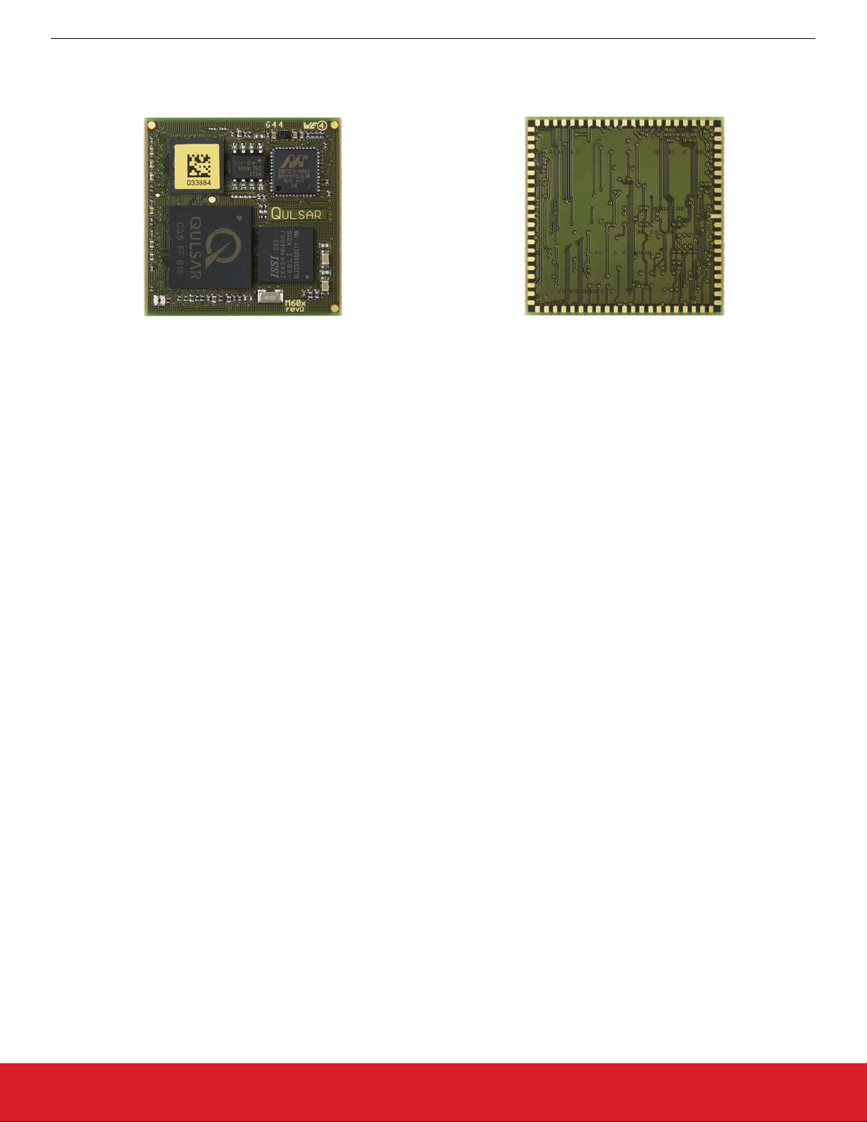
1. General Description
This section shows the M68/M64 module in approximately two times the actual size. The M68 adds an oscillator to the module.
Figure 1.1. Top Side and Bottom Side Views
1.1 Key Feature
•
Low power microprocessor technology with hardware timestamping
• 8 Mbytes SDRAM memory, 2 Mbytes flash memory
• 10/100/1000 Ethernet PHY with full PTP functionality
• RGMII interface to Host, or to an external PHY. For the M68 this includes full PTP functionality.
• Timing interface including PPS, TOD, syntonized frequency
• Comprehensive IEEE 1588-2008 implementation and SyncE support
• Communication servers for serial ports, Telnet and SSH
• Edge pads for surface mount to host boards
• RoHS and WEE compliant
• Built-in SNTP server
• Wirespeed pass-through eliminating the need for a switch in many applications
1.2 Host Interface
The RGMII Host Interface of the module is intended to be connected directly to a generic RGMII interface offered by the host, or an
RGMII PHY. The designer can choose voltage levels for adaptation to his RGMII port of the host system.
For applications with host processors offering only an SGMII interface, a PHY IC such as the 88E1512 from Marvell that converts between SGMII and RGMII needs to be added.
1.3 Communication Interfaces
The M68/M64 offers three asynchronous serial ports besides the two Ethernet ports. Advanced users with the Development Kit will also
have access to other serial and parallel interfaces including an analog section to connect to other peripherals outside the module.
1.4 JSON Machine-to-Machine Communications
New with Firmware release 3.0 is the addition of JavaScript Object Notation (JSON) structured configuration information. This greatly
simplifies the development of software on host systems to interface with the M64/M68.
silabs.com | Building a more connected world. Rev. 0.1 | 8
Page 9
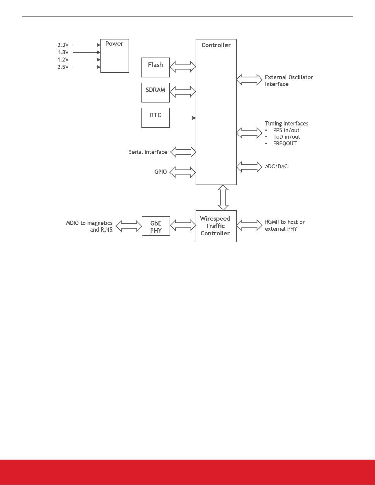
1.5 Block Diagram
M68/M64 Module Data Sheet
General Description
Figure 1.2. M68/M64 Block Diagram
silabs.com | Building a more connected world. Rev. 0.1 | 9
Page 10

M68/M64 Module Data Sheet
Packaging
2. Packaging
2.1 Dimensions
The module dimensions match the standard for a LGA-84 package, with exception for the height. The height varies over the module
surface, with maximum and minimum values given below.
When soldered directly to the motherboard, the module’s distance to that board depends on the amount of solder used but can usually
be considered to be zero.
Figure 2.1. Dimensions for M68/M64 (unit: mm)
Note: The height may vary with component vendor specification.
2.2 Recommended Land Pattern
This is the recommended PCB land pattern for direct soldering of the M68/M64 module to a host board for all designs.
Figure 2.2. Recommended Land Pattern (unit: mm)
silabs.com | Building a more connected world. Rev. 0.1 | 10
Page 11
M68/M64 Module Data Sheet
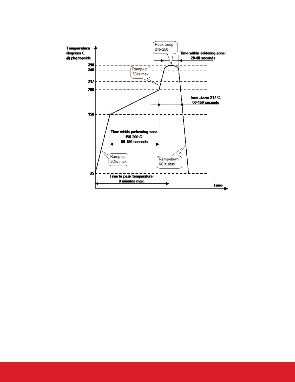
2.3 Soldering and Handling
the M68/M64 is a RoHS-compliant device, it is designed to tolerate lead-free soldering processes. The diagram below shows the
Since
recommended soldering profile for the device.
Packaging
Figure 2.3. Reflow Soldering Profile
The M68/M64 is classified as MSL 3.
2.4 Tape and Reel
M68/M64 is delivered on tape and reel and this section describes the orientation of the LGA components and the tape used for its
The
packaging.
silabs.com | Building a more connected world. Rev. 0.1 | 11
Page 12
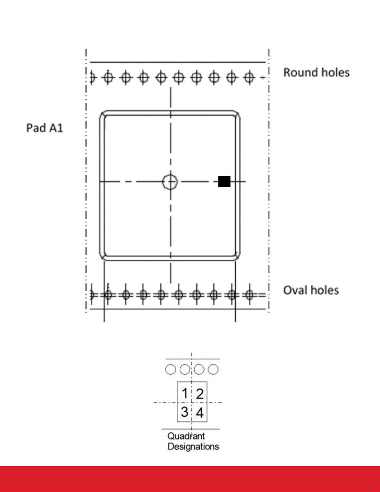
2.4.1 Pin 1 Orientation
Part orientation for tape and reel is illustrated below. The Pin 1 marker is between quadrants 3 and 4.
M68/M64 Module Data Sheet
Packaging
silabs.com | Building a more connected world. Rev. 0.1 | 12
Page 13

2.4.2 Tape and Reel Specification
M68/M64 Module Data Sheet
Packaging
Package Tape width
(mm)
Pitch
(mm)
Reel size
(mm)
Devices
per reel
LGA84 44 36 330 250
silabs.com | Building a more connected world. Rev. 0.1 | 13
Page 14

M68/M64 Module Data Sheet
LED Description
3. LED Description
The module has two on-board LEDs. See 19. Appendix 4: Troubleshooting LED Error Codes for more information. One LED is green
which shows the status of the boot sequence. This LED can be controlled by the user using firmware. The other LED is red and will light
up briefly at the start-up of the system. If the red LED keeps being lit, the system is not operating properly. This LED is not user controllable.
silabs.com | Building a more connected world. Rev. 0.1 | 14
Page 15

M68/M64 Module Data Sheet
Pin List
4. Pin List
The term “pin” used in the following table and throughout this document refers to one of the 84 pads on the bottom side of the module.
Pin 1 is located in the middle of the left side of the module when viewed from the top, see Figure 2.1 Dimensions for M68/M64 (unit:
mm) on page 10. The rest of the pins are enumerated counter-clockwise around the module from this pin.
The codes in the Type column below are: I for Input, O for Output, B for Bidirectional, P for Power, (PU) for Pull Up, and (PD) for Pull
Down.
Most pins have 3.3 Volts signaling levels. In the Description column pins not belonging to the 3.3 Volts region, e.g., those pins powered
by the External RGMII interface, are noted.
Pin Group Pin # Pin Name Type Description
RGMII 2 MIRQ0 I Ext. GbE PHY Interrupt
Powered by VCC_RGMII
3 MCKOUT1 O 25 MHz Clock.
3.3 Volts output.
Not suitable for clocking external
PHY.
Misc. 4 MRXOUT O RTC test / Active high power supply
wake-up output
5 MWAKE I (PD) Active high wake-up input
Clock 6 CPUCLK I External clock input (1.8 V level)
Misc. 7 MRSTOUT O Active low reset output
Time 8 TODIN I Time of day in
9 TODOUT O Time of day out
GPIO 10 PF2 B Port F GPIO
11 PF1 B
12 PF5 B
13 PF4 B
14 PF7 B
15 PF0 B
16 PF3/LOCK B
17 PF6 B
Analog 19-21, 23 ACH0-ACH2, ACH3 I Analog to Digital Converter multi-
plexer inputs
24, 25 AOUT0, AOUT1 O Digital to Analog Converter outputs
26 EXTREF I Optional external voltage reference
input for ADC
GPIO/Async.
Serial ports
silabs.com | Building a more connected world. Rev. 0.1 | 15
27-30 PJ0_UTX1, PJ1_URX1,
PJ2_URTS1, PJ3_UCTS1
31-34 PE0_UTX2, PE1_URX2,
PE2_URTS2, PE3_UCTS2
B Port J bits 0-3 / Serial port 1
B Port E bits 0-3 / Serial port 2
Page 16

Pin Group Pin # Pin Name Type Description
M68/M64 Module Data Sheet
Pin List
GPIO / SPI / Generic Serial
Interface
35-38 PE4_UTX3, PE5_URX3,
PE6_URTS3, PE7_UCTS3
B Port E bits 4-7 / Serial port 3
39 PB7_PC0 B See Pin descriptions
40 PD5_GSIIN B Port D bit 5 / SPI MISO / GSI input
41 PD7_GSICK B Port D bit 7 / SPI clock / GSI clock
42 PD6_GSIIO B Port D bit 6 / SPI MOSI / GSI bidir-
ectional
Ethernet 44,45 LED2,LED1 O RJ45 LED´s
46,47
48,49
50,51
52,53
MDI_A+,MDI_AMDI_B+,MDI_BMDI_C+,MDI_CMDI_D+,MDI_D-
B Ethernet, direct connection to mag-
netics
Debug 54 MSDIN I (PU) Serial debug data in
55 MSDOUT O Serial debug data out
56 MRESET I (PU) Active low reset input
57 MIRQOUT O Active low debug interrupt
58 MIRQ1 I Shared Interrupt
59 MCKOUT0 O Debug clock
62 WP I (PD) Active low flash write protect
Time & Frequency 66 FREQOUT_2 O Secondary Frequency out. Identical
signal to FREQOUT
67 FREQOUT O Frequency out
68 PPSIN I Pulse per second in
69 PPSOUT O Pulse per second out
RGMII
70 PB1_MDIO B Ext. GbE PHY Control (MDIO)
Powered by VCC_RGMII
All pins Powered
71 PB2_MDC O Ext. GbE PHY Control (MDC)
by VCC_RGMII
Supply
73,74 TXD0-TXD1 O TX Data
Powered by VCC_RGMII
75 TX_CTL O RGMII control
76 TX_CLK O TX Clock
77,78 TXD2-TXD3 O TX Data
79-80 RXD0-RXD1 I RX Data
81 RX_CTL I RGMII control
82 RX_CLK I RX Clock
83,84 RXD2-RXD3 I RX Data
silabs.com | Building a more connected world. Rev. 0.1 | 16
Page 17

Pin Group Pin # Pin Name Type Description
M68/M64 Module Data Sheet
Pin List
Supply 1,22,
GND P Ground
43,64
18 VBAT P 3V battery backup
60 VCC33 P 3.3V power supply
61 VCC25 P 2.5V power supply
Can be connected to 3.3 V power
supply at the cost of slightly higher
power consumption.
63 VCC18 P 1.8V power supply
65 VCC12 P 1.2V power supply
72 VCC_RGMII P RGMII power supply. Connect to
same voltage as the external PHY.
4.1 Pin Descriptions
Here are pin descriptions for designing with the module.
4.1.1 Analog Control of Oscillator
• (M68) AOUT1: Analog output used for controlling the frequency of the crystal oscillator. If an external voltage controlled frequency
source is used, this signal should be used to control it.
• (M64) AOUT1: Analog output used for controlling the frequency of the external voltage controlled frequency source.
• ACH0: Analog input used to measure the control voltage on external TCXO/OCXO.
• PB7: Connected together with PC0 on the module. Intended for use as SPI slave select, interconnection is for backwards compatibility. Only one of the GPIOs should be used to control this pin, the other should be tristated.
4.1.2 Write Protection
WP: This pin is connected to the write-protect pin of the on-board flash device. When pulled low or left open, the boot sector of the flash
is write-protected. Typically, only pulled high to do initial flash programming during manufacturing.
4.1.3 Serial Ports
There are three asynchronous serial ports. The identical ports are named COM1, COM2 and COM3 and are located on pins 24 – 38 of
the module.
The serial ports have hardware flow control using RTS/CTS, support several communication options with different combinations of parity, stop bits and character length, and are capable of baud rates from 300 bit/s up to 921,600 bits/s.
4.1.4 PF3/LOCK Pin
The PF3/LOCK pin can be configured to indicate that the PTP loop is locked. See the ptp2 lock command.
silabs.com | Building a more connected world. Rev. 0.1 | 17
Page 18

M68/M64 Module Data Sheet
4.2 Clocking
default the M68/M64 supports an external oscillator of 20 MHz. If another frequency is used, the PLL register (designated Configura-
By
tion Block Register 4, CRB4) needs to be changed.
The CRB4 register has 3 fields, as shown in the following table:
CRB4 Bits Description Allowable Values
Bit 7 Pll_frange Should be set to 1
Pin List
Bits 6-2 pll_n - PLL frequency multiplication factor
0 – sets dividend to 32
dividend.
1 – sets dividend to 1
2 – sets dividend to 2
:
:
31 – sets dividend to 31
Bits 1-0 Pll_m – PLL frequency multiplication factor
0 – sets divisor to 5
divisor.
1 – sets divisor to 1
2 – sets divisor to 2
3 – sets divisor to 3
The output frequency is calculated as the external oscillator frequency x ( pll_n / pll_m). The resulting output frequency must be 150
MHz and the external oscillator frequency multiplied by 4 may not exceed 167 MHz.
The PLL register can be set using the “out crb4 0xNN” command in the system.ini file, and which will be run at powerup.
Example
CRB4 setting for 20 MHz external oscillator, “out crb4 0xbe”, which sets pll_n/pll_m to 15/2, and the resulting output frequency
of 150 MHz.
Example CRB4 setting for 10 MHz external oscillator, “out crb4 0xbd”, which sets pll_n/pll_m to 15/1, and the resulting output frequency
of 150 MHz.
One important characteristic to remember when using an external oscillator other than 20 MHz: The communication with the M68/M64
might be difficult before the proper PLL settings are in place. For example, when using an external 10 MHz oscillator, the serial port
communications would occur at 57600 baud, instead of 115,200.
NOTE: CPUCLK is a 1.8 V level pin. It must not be connected directly to a 3.3 V level oscillator output. A resistor or capacitive voltage
divider is enough to ensure that the voltage doesn’t exceed 1.8 V.
If the external oscillator has voltage control, it can be connected to the AOUT1 analog output. The control range of this pin is from 0.8 V
to 2 V. Fixed-frequency external oscillators can also be used, but then the FREQOUT frequency will not be syntonized.
4.3 Power Supply
4.3.1 Digital Power Supply
The module has five different power pins. Required power sources are 3.3, 1.8 and 1.2 Volts.
The use of an optional 2.5 V source will slightly decrease the power consumption. Otherwise the VCC25 pin must be connected to
VCC33.
The RGMII interface is powered by the user's system and the VCC_RGMII pin shall be connected to the systems power source. In the
case the RGMII interface is not intended to be used, the VCC_RGMII pin still must be connected to a power source. VCC33 is the best
choice.
silabs.com | Building a more connected world. Rev. 0.1 | 18
Page 19

M68/M64 Module Data Sheet
Pin List
4.4 Time I/O
4.4.1 Reference Time Input
consists of signals PPSIN and TODIN, and is intended for connection to an external time source like a GNSS receiver or similar. If
It
one or both signals are not used, they can be left unconnected.
PPSIN expects a pulse-per-second signal with LVTTL levels. Rising edge should be on second boundary, the pulse width is not critical.
TODIN should receive time-of-day information, for example in NMEA 0183 format. The levels must be LVTTL and polarity will be detected. The current FW supports 4800 or 9600 baud 8N1 on the TODIN pin.
4.4.2 Precision Time Output
The interface consists of signals PPSOUT, TODOUT, FREQOUT and SYNTFREQ.
PPSOUT outputs a pulse-per-second signal with LVTTL levels. Pulse width, frequency, phase and polarity of this signal can be controlled by software. For more information, see 18. Appendix 3: PTP Command Reference.
TODOUT outputs time-of-day at LVTTL levels, for example in NMEA 0183 format. Baudrate can be set to 4800 or 9600 baud 8N1. For
more information, see 18. Appendix 3: PTP Command Reference.
(M64) FREQOUT outputs a syntonized frequency in the MHz range and at LVTTL levels. The frequency is software selectable
5/10/20/25 MHz. The frequency will only be syntonized (kept in phase with PTP or GNSS time) if the external oscillator is voltage controlled by analog output AOUT1 from the module.
(M68) FREQOUT outputs a syntonized frequency in the MHz range and at LVTTL levels. The frequency is software selectable
5/10/20/25 MHz. The frequency will only be syntonized (kept in phase with PTP or GNSS time) if the internal crystal oscillator is used or
if the external oscillator is voltage controlled by analog output AOUT1 from the module.
The SYNTFREQ is the same as the FREQOUT.
silabs.com | Building a more connected world. Rev. 0.1 | 19
Page 20

M68/M64 Module Data Sheet
5. Specifications
5.1 Metrics
Metric Value
Dimensions 29.2 x 29.2 x 3.3 mm
Weight 3.0 g
Operating temperature -40°C – +85°C, ambient
Storage temperature -40 – +150 °C
5.2 Absolute Maximum Ratings
Parameter Symbol Min Max
Specifications
Supply voltage 3.3 V V
Supply voltage 2.5 V V
Supply voltage VCC_RGMII V
Supply voltage 1.8 V V
Supply voltage 1.2 V V
RTC battery backup supply V
I/O voltage (CPUCLK pin) V
I/O voltage (all other pins) V
ESD tolerance (Ethernet differential pairs, human body model) V
ESD tolerance (all other pins, human body model) V
CC33
CC25
CC_RGMII
CC18
CC12
BAT
IO18
IO33
ESDE
ESD
-0.3 V 3.6 V
-0.3 V 3.6 V
-0.3 V 3.6 V
-0.3 V 2.5 V
-0.3 V 1.32 V
-0.3 V 4.0 V
-0.3 V 2.16 V
-0.3 V 4.0 V
6 kV
2 kV
Permanent device damage may occur if the absolute maximum ratings are exceeded. These are stress ratings only, and functional
operation should be restricted to within the conditions detailed in the next section.
Exposure to absolute maximum rating conditions for extended periods may affect the device’s reliability.
5.3 Recommended Operating Conditions
Parameter Symbol Min Typ Max
Supply voltage 3.3 V V
Supply voltage 2.5 V V
Supply voltage VCC_RGMII V
CC33
CC25
CC_RGMII
3.15 V 3.3 V 3.45 V
2.38 V 2.5 V 2.62 V
3.15 V 3.3 V 3.45 V
2.38 V 2.5 V 2.62 V
1.71 V 1.8 V 1.89 V
1.43 V 1.5 V 1.57 V
1.14 V 1.2 V 1.26 V
Supply voltage 1.8 V V
Supply voltage 1.2 V V
RTC battery backup supply V
I/O voltage (CPUCLK pin) V
silabs.com | Building a more connected world. Rev. 0.1 | 20
CC18
CC12
BAT
IO18
1.71 V 1.8 V 1.89 V
1.14 V 1.2 V 1.26 V
2.7 V 3.63 V
0 V 1.98 V
Page 21

M68/M64 Module Data Sheet
Specifications
Parameter Symbol Min Typ Max
I/O voltage (RGMII pins) V
IO_RGMII
-0.3 V V
CC_RGMII
V
CC_RGMII
0.5V
I/O voltage (all other pins) V
IO33
0 V 3.63 V
5.4 DC Electrical Characteristics
Parameter Symbol Min Typ Max
Power consumption 1060 mW
Supply current I
RTC backup current (V
= 3.0 V,
BAT
CCxx
I
BAT
(see table below)
5.5 µA
VCC = 0 V)
Input low voltage (except CPUCLK) V
Input high voltage (except CPUCLK) V
IL
IH
2.0 V
0.8 V
Input/tristate leakage current |II| 1 µA 10 µA
Output low voltage (|IOL| = max) V
Output high voltage (|IOH| = max) V
OL
OH
2.4 V
0.4 V
Output drive current (GPIO pins) |IOL|,|IOH| 2/8 mA
+
Supply currents per voltage for different choice of host RGMII voltages. These are preliminary values for a gigabit speed connected
module:
1.8 V RGMII option
V mA
1.2 138
1.8 115
2.5 15
3.3 200
Note: The final power consumption will depend on how the user designs his PCB. The numbers given in the table are maximum values
for
a well-designed board with a 1.8 V feed of the external RGMII port. Increasing this to 3.3 V is optional, but this will increase the total
power consumption.
Note: When planning to use the module in an existing design, the module contains a network side PHY. The existing PHY must be
removed, also when calculating power consumption as the PHY consumes the majority of the total.
5.5 AC Electrical Characteristics
Parameter Symbol Min Typ Max
(M68) On-board main oscillator frequency f
On-board RTC oscillator frequency f
OSC
RTC
20 MHz
32768 Hz
Core & SDRAM frequency (must be typical value for Ether-
f
CORE
20 MHz 150 MHz 167 MHz
net operation)
External oscillator frequency on CPUCLK f
silabs.com | Building a more connected world. Rev. 0.1 | 21
EXT
5 MHz 41.7 MHz
Page 22

M68/M64 Module Data Sheet
PCB Design Considerations
6. PCB Design Considerations
This chapter should be read before starting a new design.
6.1 Land Pattern
See section 2.2 Recommended Land Pattern and Accepted Land Pattern for further information.
6.2 Power
The module has five connections for five different voltages. Three of those voltages are mandatory, two power pins can be joined to the
cost of slightly increased power dissipation. One voltage is used for an optional PHY. The module also comprises four connections to
GND. An optional backup battery, for the RTC, can be connected to the module.
6.2.1 Required Voltage
For Maximum and Operating Voltage Levels see sections 5.2 Absolute Maximum Ratings and 5.3 Recommended Operating Condi-
tions.
Maximum Supply Currents during operation are listed in 5.4 DC Electrical Characteristics. During start-up, the current consumption can
momentarily be higher.
Pin Name Voltage Description
VCC33 3.3 V This voltage is used for driving signals on the module and for the /O’s of
the module.
VCC25 2.5 V or 3.3 V If connected to 3.3 V there will be slightly higher power dissipation.
VCC18 1.8 V Used for the PHY located on the module.
VCC12 1.2 V Power for the devices on the module.
VCC_RGMII 1.2 V to 3.3 V If an optional external PHY is used this pin must be connected to the same
voltage source as the PHY’s RGMII interface. The pin must not be left unconnected. If no external PHY used this pin should be connected to
VCC33.
This power pin is used only to drive the external RGMII interface.
VBAT 3 V If backup is required, this pin shall be connected to a 3 V lithium coin cell
battery. No current is drawn from the battery when power is available on
pin VCC33.
silabs.com | Building a more connected world. Rev. 0.1 | 22
Page 23

M68/M64 Module Data Sheet
PCB Design Considerations
6.2.2 Decoupling Capacitors
is important that the selected decoupling capacitors are specified correctly, are placed close to the module and, to minimize induc-
It
tance, are connected with as wide tracks as possible. The use of power planes is of course the ideal solution.
Decoupling capacitors on the module itself are placed very close to the on-module circuits. Those capacitors will provide for the immediate current requirement. Bulk capacitance must be placed external to the module. All 4.7µF capacitors mentioned below shall be
placed as close as possible to the corresponding module connection. The larger capacitors, 100µF, can be placed further away from
the module.
Pin Name Decoupling Capacitors
VCC33 Connect one 4.7 µF and one 100 µF capacitor to this pin.
VCC25 Connect one 4.7 µF and one 100 µF capacitor to this pin.
VCC18 Connect one 4.7 µF and one 100 µF capacitor to this pin.
VCC12 Connect two 4.7 µF capacitors to this pin.
VCC_RGMII Connect one 4.7 µF and one 100 µF capacitor to this pin.
The decoupling capacitors must have the following specifications:
Ceramic X7R or X5R, 6.3 V.
•
• 100 µF: max size 1210, ESLmax 5nH, 10 mOhm < ESR <60 mOhm.
• 4.7 µF: max size 0805, ESLmax 2nH, 10 mOhm < ESR <60 mOhm.
6.3 Clock Signal MCLKOUT1
Clock signals must be treated with great care, with signal integrity in mind. For this reason, MCLKOUT1 has a series termination resistor placed on the module, no further termination is required. The trace from the module must not have any stubs. If more than one load,
those loads should preferably be placed close to each other. The trace shall preferably have 50-65 ohm line impedance.
This clock signal was intended to drive an external PHY. However, it has been shown that it is not suited for this purpose due to jitter.
We suggest using an external 25 MHz oscillator to drive the external PHY instead.
6.4 Ethernet Interface
The four pairs of differential signals driving the magnetics are placed close to each other on one side of the module. The length of the
traces for each pair shall be as equal as possible and so should the length of the four pairs.
Drivers for the LEDs, signaling connection status, are of Open Collector type. A resistor of nominally 470 ohms shall be placed between
VCC33 and the anode side of the LEDs.
6.4.1 Magnetics
The following is a list of magnetics that can be used with the module. The list is not complete, and all magnetics listed are not tested
together with the module. All listed magnetics are single port RJ-45 connectors with integrated magnetics of 3 wire choke type.
Manufacturer Part Number
Link-PP Electronics LPJK2065AONL
LPJK0036AINL
Pulse Electronics JK0-0136NL
JK0654219
Foxconn JFM38010-01S1-4F
Belfuse 0813-1X1Y-43
SI61021F
silabs.com | Building a more connected world. Rev. 0.1 | 23
Page 24

M68/M64 Module Data Sheet
PCB Design Considerations
6.5 RGMII Interface
interface is clocked at 125 MHz, when running GbE. Needless to say great care must be taken during design. Connections to the
This
two channels, TX and RX, are adjacent on the module, having respectively clock in the center of the connections.
RGMII clocking is source synchronous, what is the RX clock is generated by the PHY and the TX clock by the module. All traces within
a channel must have the same length. Delay of the clock, sampling in the middle of the data-eye, is taken care of by the external PHY
and the RGMII interface on the module.
silabs.com | Building a more connected world. Rev. 0.1 | 24
Page 25

M68/M64 Module Data Sheet
Application Software
7. Application Software
The M64 and M68 are quite similar. In the CLI commands that follow, the M68 commands are given. The full details of a command are
available via help commands in the CLI.
For the M64 the parameter, "port_number" is always 1. For the M68, "port_number" is either 1 or 2, the default is 1.
For the M64 the parameter, "iface" is always enet0. For the M68, it is either enet0 or enet1.
7.1 System Access
See the Quick Start Guide for setting up communication to the module in a P60 Evaluation Kit. To logon to the system the username is
“root”, with password “root” as the initial credentials.
You can change them later with the passwd command and add or delete users in the database, see the passwd.ini section.
On entering the system, you will see a prompt and an identifier for the system. The interface is very similar to UNIX.
7.2 System Files
The system directory A:/system contains firmware files and a number of system initialization and configuration files. These are listed in
the Appendix 1 for reference. The files most applications should check and modify are the system.ini and startup.ini to setup the module
in its environment and give the PTP engine the parameters for the synchronization scheme.
7.3 Module Shell Environment
The shell, called ISH, is responsible for the high-level system initialization, for execution of various servers and for providing a UNIX-like
command interface.
7.3.1 High-Level Initialization
The shell startup code completes initialization and configuration of the system performing the following tasks:
• Initializes the serial port interface
• Registers stdout and stderr functions
• Reads the Hardware Identification String from the flash memory
• Reads and processes a shell configuration file ish.ini.
• Reads and processes a system configuration file system.ini
• Initializes and starts a Serial server
• Configures a hostname
• Initializes and configures TCP/IP stack software
• Starts FTP and Telnet servers
• Sets the Time Zone and Daylight Saving
• Reads and executes startup file startup.ini
7.3.2 System Commands
The shell includes Serial server, Telnet server and FTP server. The shell starts them automatically during startup, if specified in the
system configuration file. Otherwise they can be started and stopped manually using startserver and stopserver commands.
7.3.3 Communication Servers
The shell includes Serial server, Telnet server and FTP server. The shell starts them automatically during startup, if specified in the
system configuration file. Otherwise they can be started and stopped manually using startserver and stopserver commands.
7.3.3.1 Serial Server CLI
The Serial server provides the command-line user interface over a serial channel. The serial port number and port parameters can be
specified though environment variables.
silabs.com | Building a more connected world. Rev. 0.1 | 25
Page 26

M68/M64 Module Data Sheet
Application Software
7.3.3.2 Telnet Server CLI
Telnet server provides the command-line user interface over a TCP/IP communication channel. The TCP port number and the
The
server priority can be specified though the environment variable.
7.3.3.3 SSH Server
The SSH server is not started by default but has to be started manually using the command:
startserver –d
Note: For the current implementation, initialization takes about 30 seconds and establishing the connection about another 60 seconds.
7.3.3.4 FTP Server
The FTP server provides a remote access to the local file system. It supports both get and put operations. The number of simultaneous
connections and the server priority can be specified through environment variables.
7.3.3.5 JSON
The command interface (default is COM3) can be used in either CLI/HMI command mode or JSON mode. The JSON mode is turned on
or off with the following commands:
ptp2 engine json on
ptp2 engine json off
See 12. JSON Usage
for more details.
7.4 Passthrough
The passthrough mode allows a system with two Ethernet interfaces to act as a "synchronization gateway" for non-PTP hosts.
On its primary Ethernet port such "gateway" is connected to a network which transports data and PTP synchronization. To its secondary Ethernet port, the non-PTP system is connected. The "gateway" participates in PTP activity acting as a PTP slave and synchronizing its local clock. The PTP traffic is filtered out while non-PTP data is passed through to the host along with PPS/TOD/FREQ-out synchronization signals.
The command to turn on and off pass-through is:
ifconfig frwd [on|off]
On the M68 the secondary (host-side), Ethernet is available for user or applications such as a general-purpose network interface.
On M64, the secondary (host-side), Ethernet interface is not available for user or applications as a general-purpose network interface, it
is used only for pass-through and it is completely transparent from either host or network side.
silabs.com | Building a more connected world. Rev. 0.1 | 26
Page 27

M68/M64 Module Data Sheet
Application Software
7.5 VLAN
M68/M64 supports VLAN tagging. If VLAN is used in combination with PTP, the VLAN needs to be set before the PTP engine is
The
started.
To enable VLAN on the interface, use the command:
ifconfig [iface] vlan [parameters]
where [iface] is the interface name. If not given, 'enet0' will be used.
[parameters] can be
off - send and receive untagged frames only
none - send untagged frames, receive untagged and priority tagged frames
0 [prio_code] - send priority-tagged frames, receive untagged and priority tagged frames
<vlan_id> [prio_code] - send and receive vlan-tagged frames only
For example:
ifconfig vlan 1588 0
To disable VLAN on the interface, use the command:
ifconfig enet1 vlan off
7.6 MDIO
The M68/M64 supports the possibility to control and monitor equipment such as a PHY connected over MDIO. To enable MDIO mode,
use the command
ifconfig mdio
This will disable all other access to the MDIO registers to avoid conflicting writes to the page register. To then read from MDIO registers
use the command
<reg>
And to write to a MDIO register in the exclusive MDIO mode use
<reg> <value>
To exit from the exclusive MDIO mode, type “q”.
For example, to enter MDIO mode and write 0x4885 to register 18 on page 3 (reg 22 is page register):
A:/root> ifconfig mdio
Enter exclusive MDIO mode on enet0
22 3
22: 0x0003
18
18: 0x4b85
18 0x4885
18: 0x4885
q
Quit exclusive MDIO mode on enet0
A:/root>
It is also possible to read or write directly to a MDIO register without entering the exclusive mode:
ifconfig mdio <reg> <value>
but beware any page register settings.
simplify for the user, some common operations on the PHY has been defined as specific commands: to manage link speed and
To
duplex, to reset the PHY and to manage SyncE master/slave behavior.
silabs.com | Building a more connected world. Rev. 0.1 | 27
Page 28

7.7 Link Speed
The PHY link speed and duplex can be controlled by the command
ifconfig [iface] link [parameters]
where [iface] is the interface name. If not given, 'enet0' will be used.
M68/M64 Module Data Sheet
Application Software
[parameters]
can be one of the following modes: 1000F, 1000H, 100F, 100H, 10F, 10H which disables autonegotiation and force the
interface into the desired speed and duplex (F – full, H – half) or auto [mode_mask] which will enable autonegotiation and optionally set
advertised modes. If mode_mask is not given all supported modes will be advertised, i.e. 1000F|1000H|100F|100H|10F|10H
For example, to set 100Mb/s Full duplex:
ifconfig link 100F
or set interface 0 to autonegotiation with only 1000Mb/s and 100Mb/s full duplex supported.
Ifconfig enet0 link auto 1000F|100F
7.8 PHY Reset
It is possible to reset the PHY with the following command:
ifconfig [iface] reset [options]
Where [iface] is interface name. If not given, 'enet0' will be used.
[options] can be either sw, noinit or not given at all.
If no option is given, a HW reset is performed, i.e. the reset pin of the PHY is pulled after which initialization is done.
If the option “noinit” is given also a HW reset is performed, but no initialization of the PHY is performed. This can be used when PHY
needs to be configured manually using MDIO.
The option “sw” sets the reset bit in the MDIO registers, performing a SW reset. This is of course only relevant if the PHY's MDIO interface lines are connected.
For example, to perform a HW reset of the PHY:
ifconfig reset
7.9 SyncE
For PHY devices supporting SyncE it is possible to define the direction of frequency on a link. This is only valid for 1000Base-T interfaces.
ifconfig [iface] synce [parameters]
Where [iface] is the interface name. If not given, 'enet0' will be used.
[parameters] can be
• master|slave which will disable autonegotiation and force the interface into either master or slave mode or
• auto master|slave which will enable autonegotiation with either master or slave preference
If no parameter is given, current resolved state will be reported.
For example, setting the module to be preferred SyncE master:
ifconfig synce auto master
silabs.com | Building a more connected world. Rev. 0.1 | 28
Page 29

7.10 SFP
There is support for managing an SFP connected to the specified network interface.
ifconfig [iface] sfp [parameters]
Where [iface] is the interface name. If not given, 'enet0' will be used.
[parameters] can be
raw, which prints SFP information in raw hex format
state, which shows state of LOS, enable, presence and fault
enable will enable the SFP transmitter
disable will disable the SFP transmitter
mdio <reg> will perform single read from MDIO register in SFP PHY
mdio <reg> <value> will perform single write to MDIO register in SFP PHY
If no parameter is given, prints formatted SFP information.
M68/M64 Module Data Sheet
Application Software
silabs.com | Building a more connected world. Rev. 0.1 | 29
Page 30
M68/M64 Module Data Sheet
IEEE 1588/PTP Engine
8. IEEE 1588/PTP Engine
The M64 and M68 are quite similar. In the CLI commands that follow, the M68 commands are given. The full details of a command are
available via help commands in the CLI.
For the M64 the parameter, "port_number" is always 1. For the M68, "port_number" is either 1 or 2, the default is 1.
For the M64 the parameter, "iface" is always enet0. For the M68, it is either enet0 or enet1.
8.1 General Features
The IEEE 1588/PTP Engine (PTP Engine) has the following features:
• Implements an ordinary clock in accordance with IEEE Std 1588™-2008
• M68 implements boundary clock in accordance with IEEE Std 1588™-2008
• Fully flexible to comply with Default Telecom and Power Profiles
• Supports both GNSS and PTP as the primary and backup time source
• Built-in SNTP server
• Supports 5 different operational modes
• Provides the command-line interface (can be configured and monitored either locally via Terminal or over the network via Telnet or
SSL)
• Supports PTP Management interface (can be configured and monitored over the network from a PTP Management station)
• Provides a rich set of APIs
• Uses high-precision hardware timestamp engine
• Can be partially customized by the customer
8.2 PTP Software Implementation
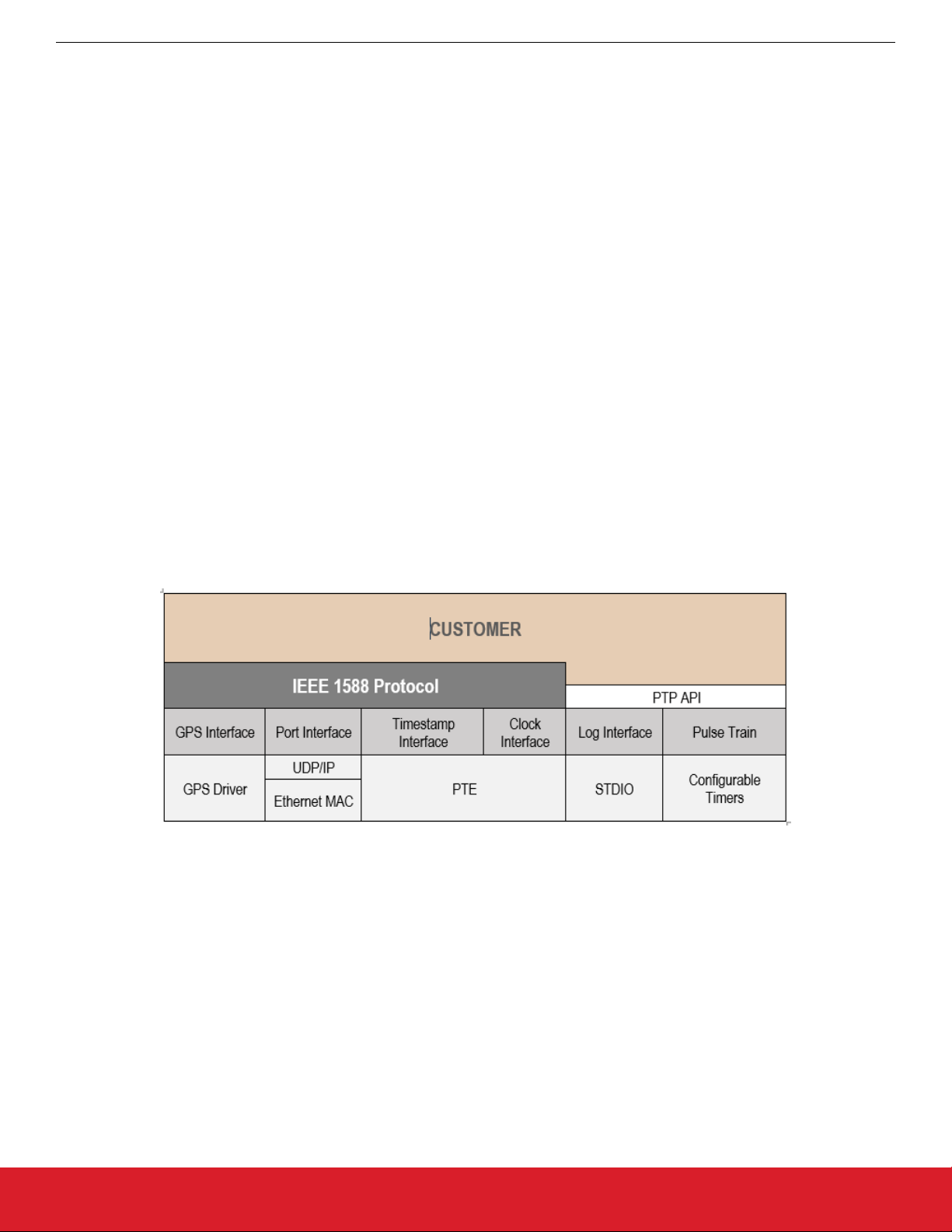
PTP software is divided into three layers; Protocol Layer, OS Abstraction Layer and the OS Layer.
Figure 8.1. PTP Layers
8.2.1 Protocol Layer
protocol layer contains the PTP engine which is implemented according to the IEEE 1588-2008 standard. The protocol engine en-
The
capsulates a number of functions necessary to run the PTP clock. Among those functions are best master clock algorithm, PTP message handling and maintaining of PTP clock data sets.
8.2.2 OS Abstraction Layer
The OS abstraction layer implements a number of interfaces between the protocol engine and the underlying operating system.
8.2.2.1 GNSS Interface
The GNSS interface contains functionality for GNSS synchronization. This interface is used when running the grandmaster clock.
silabs.com | Building a more connected world. Rev. 0.1 | 30
Page 31

M68/M64 Module Data Sheet
IEEE 1588/PTP Engine
8.2.2.2 PTP Interface
interface PTP encapsulates the functions of the PTP environment and therefore only provides the functions that must be callable
The
from the outside of the protocol engine. PTP is a wrapper of PTP environment – it represents the API of the PTP protocol.
8.2.2.3 Port Interface
The port interface is used to send and receive PTP messages. It makes use of the functions the OS provides (e.g. sockets) in order to
communicate over the network.
8.2.2.4 Timestamp Interface
The time stamp interface is used to pass time stamps for Sync and Delay_Req messages to the PTP protocol engine. It also implements the connection which is used to read the timestamps from the timestamp unit.
8.2.2.5 Clock Interface
The clock interface provides functions to read, write and configure the local clock. The clock interface uses the clock driver functions
(set time, get time, drift compensation etc.) in order to access the clock.
8.2.2.6 Log Interface
Through the log interface the protocol engine can output log information. The log provides human readable information that shows current settings and current state of the protocol engine. This log information can be monitored either via a serial port or TCP/IP.
Log output is initiated and controlled though the Human Machine Interface.
8.3 GNSS Driver
The GNSS driver consists of a PPS Receiver unit and a GNSS Time Receiver.
When a PPS signal from the attached GNSS unit is received by the GNSS Receiver, the signal is timestamped by the PTP timestamp
unit. The timestamp is then delivered to the GNSS Interface where it is put in an event queue for processing by the protocol stack.
The GNSS Time Receiver receives time of day information from the GNSS unit. This time information specifies the date and time of the
PPS signals.
8.4 AccuTime Software
AccuTime software consists of configurable timers and MAC hardware with timestamp capabilities.
The MAC hardware reports timestamps for all incoming or outgoing Ethernet frames.
The PTP engine receives and sends PTP messages through the TCP/IP stack using a socket interface. It accesses the timestamp list
to get timestamps for these messages.
The MAC hardware is augmented with input timestampers and output coincidence triggers to allow it to set timestamps at input events
and cause output events at certain times.
8.5 PTP API
The PTP engine provides a rich set of C API calls that the application programmer can use to start and control the engine. This C API is
only open to customers which have the Developer IDE software installed.
silabs.com | Building a more connected world. Rev. 0.1 | 31
Page 32

M68/M64 Module Data Sheet
IEEE 1588/PTP Engine
8.5.1 Starting/Stopping the PTP Engine
PTP engine runs as a separate thread and there can only be one instance of the PTP engine running at one time. An application
The
can start the PTP engine by a call to the function PTP2_Start().
As the parameter to that function, a pointer to the configuration structure is passed. In this structure one can specify whether a pulsetrain needs to be enabled and a mode for the PTP engine operations (see detail below).
The PTP engine can also be automatically started at boot time by the Shell, ISH. For more information about ISH see the ISH documentation in the Profile Help.
To stop the PTP engine, use the PTP2_Stop() function or the corresponding shell command.
8.5.2 Pulse Train
A pulse-train can be generated by the PTP engine. The pulse-train can be continuous or a specified number of pulses can be generated. The user can also specify the width and period of the pulse-train as well as the starting time for the pulse-train.
silabs.com | Building a more connected world. Rev. 0.1 | 32
Page 33

M68/M64 Module Data Sheet
IEEE 1588/PTP Engine
8.5.3 Human Machine Interface
PTP engine has a command interface that the user can use to manually change settings and issue different printouts from the
The
engine’s current state. The Human Machine Interface (HMI) commands can be entered either manually (from a Terminal or Telnet console) or issued by the application with the PTP2_hmi() function.
To find exact syntax of each command simply type (or send from a program) “h” – stands for Help.
When using the HMI commands, you can type either the command word or use the letter(s) in the parentheses before the command.
For example, to disable unicast negotiation, type unicast n off or type u n off. To see a list of the command set, first make sure
you are in HMI mode by typing ptp2 hmi at the prompt. Next, type help and the commands display.
The following table shows the structure of the commands
Command Example Results
command unicast or u Prints a list of subcommands.
Command subcommand unicast n or u n Prints current value of associated parameter.
Command subcommand value
unicast n off or u n off
Sets associated parameter to a different value.
The next series of tables describe each command and its associated subcommands and values. The last table shows command examples.
Clock Command Subcommand & Parameters Description
(c)clock (i)info Print clock description.
(u)user <string> Change user description.
(f)profile <default|g8265|g8275.1|
g8275.2|power [v2]>
(m)mode <oc|bc> Change clock type mode (M68 only)
(t)twostep <on|off> Change two-step mode.
(q)quality <class> <accuracy>
<variance>
Change clock profile.
Change clock quality.
(p)priority 1|2 <value> Change priority 1 or 2.
(d)domain <number> Change domain number.
(s)slaveonly <on|off> Change slave-only mode.
silabs.com | Building a more connected world. Rev. 0.1 | 33
Page 34

Port Command Subcommand & Parameters Description
(p)port <port_number> (s)state Print port state.
(m)mechanism <e2e|p2p|disable> Change or disable delay mechanism.
(p)protocol <udp|eth|udp6> Change network protocol.
(c)compatibility <on|off|auto [timeout]> Change V1 HW compatibility mode.
(a)asymmetry <value> Change delay asymmetry.
(si)sync <value> Change log sync interval.
(di)delay <value> Change min log delay request interval.
(pi)pdelay <value> Change min log pdelay request interval.
(ai)announce <value> Change log announce interval.
(rt)receipt <value> Change the announce receipt timeout.
(u)unicast <master|slave|both|disable> Enable/disable unicast operation for the
master and slave clocks.
M68/M64 Module Data Sheet
IEEE 1588/PTP Engine
(f)profile <default|g8265|g8275.1|g8275.2|power
[v2]>
(d)dscp <value> Set DSCP in PTP messages.
Change PTP profile.
Unicast Command Subcommand & Parameters Description
(u)unicast <port_number> (s)status Print port unicast information.
(n)negotiation <on|off> Enable/disable unicast negotiation.
node (m)master [add|del] <address> [clock_id]
<priority> <si|x> <di|x> [domain]
node (s)slave [add|del] <address> <ai|x> <si|
x> <di|x>
(q)query <interval> Change unicast discovery query interval.
(d)duration <value> Change unicast transmission duration.
(t)timeout <value> Change cancel acknowledge receipt time-
Change unicast master discovery table.
Change static unicast slave table.
out.
(l)limit <value> Change total unicast messages rate limit.
(f)filter (m)master [add|del] <address|*>
[clock_id] [x | [priority] [si] [di|x]]
(f)filter (s)slave [add|del] <address|*>
[clock_id] [x | [ai] [si] [di|x]
Change acceptable unicast master table.
Change acceptable unicast slave table.
Power Profile Command Subcommand & Parameters Description
(pw)power (g)gmid <0..65535> Change grandmaster ID.
(i)inacc <grandmaster> <network> Change grandmaster and network time in-
accuracy.
G.8275 Profile Command Subcommand & Parameters Description
(g2)g8275 <port_number> (p)priority <1..255> Change clock local priority.
(s)steps <1..255> Change max steps removed.
<port_number> (m)masteronly <on|off> Change port master-only attribute
silabs.com | Building a more connected world. Rev. 0.1 | 34
Page 35

M68/M64 Module Data Sheet
IEEE 1588/PTP Engine
Dataset Command Subcommand & Parameters Description
(d)dataset (d)default Print default dataset.
(c)current Print current dataset.
(m)parent|master Print parent dataset.
(t)time Print time properties dataset.
(p)port Print port dataset.
(f)foreign Print foreign master dataset.
(u)unicast Print unicast master or slave node dataset.
(pw)power Print power profile dataset.
(g1)g8265 Print G.8265 profile dataset.
(g2)g8275 Print G.8275 profile default dataset.
(g2)g8275 <port_number> Print G.8275 profile port dataset.
Time Command Subcommand & Parameters Description
(t)time (i)info Print time and synchronization information.
(s)sync Print synchronization status.
arb <time> Print or set time in +/-
SSSSSSSSS.NNNNNNNNN format.
ptp <time> Print or set time in YYYY-MM-DD
HH:MM:SS.NNNNNNNNN format.
utc <time> Print or set time in UTC YYYY-MM-DD
HH:MM:SS.NNNNNNNNN format.
ntp <server> Print or set time from NTP server specified
by name or IP address.
(t)timescale <ptp|arb> Change timescale.
(o)offset <value> Change UTC offset.
(l)leap <save|load> Print UTC leap table or save/load it into/from
file.
(l)leap 59|61 <0|1> Change leap seconds flags.
(u)update <on|off> Turn on/off automatic update of RTC time
from PTP time.
(h)holdover <value> Change period of holdover state.
silabs.com | Building a more connected world. Rev. 0.1 | 35
Page 36

M68/M64 Module Data Sheet
IEEE 1588/PTP Engine
GPS Command Subcommand & Parameters Description
(g)gps (s)status Print GPS interface information.
(n)nmea Print NMEA position/satellites information.
(p)ppsin <enable|disable> Enable/disable PPS input reception.
(t)todin <enable|disable> Enable/disable TOD input reception.
(c)class <active> <holdover> <free> Change clock state to clock class mapping.
(t)todin <required|optional> Change non-present or invalid TOD-in handling.
(d)delay <value> Change PPS-in cable delay compensation.
(f)format <nmea|ascii|cm> Change TOD-in message format.
(v)void <ignore|syntonize|holdover> Changes NMEA RMC void flag handling.
(i)interface <default|com[n]> <baudrate> Change TOD-in interface.
(m)message <string> Send message to GPS receiver via TOD interface.
cm <status> <class> <accuracy>
<variance> <source> <tt> <ft>
Change CM status to clock properties mapping.
Pulsetime Command Subcommand & Parameters Description
(pt)pulsetime (s)status Print PPS-TOD status and configuration.
(p)pulse <period> <width> Change PPS-out pulse parameters.
(d)delay <value> Change TOD-out delay after PPS-out rising
edge.
(f)format <nmea [rmc|zda|both]|ascii [utc|
local]|cm|custom>
(v)void <never|free|holdover> Change NMEA RMC Active/Void flag be-
Change TOD-out message format.
havior.
(z)zone <none|tz|dst> Change NMEA ZDA timezone/daylight
field.
cm <class> <status> Change clock class to CM status mapping.
(i)interface <default|com[n]> <baudrate> Change TOD-out interface.
(t)todout <enable|disable> Enable/disable TOD output.
(m)mode <1|2|3> Change PPS-TOD output mode (sync,
holdover, always)
1= sync
2= holdover
3= always
(e)error <value> Change error tolerance.
(a)autorestart <on|off> Turn on/off automatic restart.
start <time> <count> Start/schedule PPS-TOD output.
stop Stop/cancel PPS-TOD output.
silabs.com | Building a more connected world. Rev. 0.1 | 36
Page 37

M68/M64 Module Data Sheet
IEEE 1588/PTP Engine
Nettime Command Subcommand & Parameters Description
(nt)nettime (s)status Print SNTP server status and configuration.
(m)mode <1..4> Change server mode (unicast, manycast, broadcast,
and mixed).
1= unicast
2= manycast
3= broadcast
4= mixed
(pi)poll <0..64> Change poll/broadcast interval.
start Start SNTP server.
stop Stop SNTP server.
Engine Command Subcommand & Parameters Description
(e)engine (i)init default|nvm Reinitialize clock. Currently not supported.
(p)port <enable|disable> Change port operational status.
(e)esmc <auto|0..15|off> Enable ESMC message transmission.
(e)esmc map <class> <ssm> Change clock class to SSM code mapping.
(n)nvm save|reset Change configuration in non-volatile storage. Current-
ly not supported.
(d)debug <on|off> Turn on/off debug output.
(v)verbose <level> Change verbose level for debug output.
(m)monitor <on com[n]|off> Enable output for PTP monitor program.
(f)freqout <5|10|20|25> Change frequency output (5, 10, 20, 25 MHz).
(a)asymmetry <value> Change PHY asymmetry compensation.
Examples
Function Command
Set the sync rate to -6 p si -6
Set the delay rate to -6 p di -6
Start PPS pt start
Print list of clock subcommands c
Print value of priority1 c p 1
Set value of priority1 to 130. c p 1 130
Print value of log sync interval. p si
Set value of log sync interval to -2 (4 sync per sec). p si -2
Print content of parent dataset. d m
Print content of port dataset. d p
Print list of debug output levels. e v
Enable clock monitor program on COM3. e m 3
silabs.com | Building a more connected world. Rev. 0.1 | 37
Page 38

M68/M64 Module Data Sheet
Network Subsystem
9. Network Subsystem
The Network Subsystem, as a part of the System Software is responsible for the networking support and network communications. Its
major part is TCP/IP protocol stack software, which provides the support for TCP/IP environment and TCP/IP communications over
Ethernet and serial links.
The TCP/IP stack software was designed to be fully reentrant and multithreaded safe, as well as scalable and highly configurable. It is
compliant with standards and has a rich application programming interface (API).
9.1 TCP/IP Stack Architecture
In general, functional architecture of the TCP/IP stack is the same as in any other TCP/IP implementations. It comprises four major
layers: link layer, network layer, transport layer and application layer. These layers interact with each other via well-defined interfaces.
A Link layer provides an abstract view of a network interface device (or adapter) and isolates its details from upper layers. Link layer
includes device drivers for real or virtual (pseudo) hardware and implementations of underlying physical network protocols. Currently,
TCP/IP link layer software provides following components: driver for internal loopback adapter (pseudo-device), driver for the Ethernet
Adapter and implementations of loopback and Ethernet II protocols.
A Network layer provides the basic packet transmission service as well as addressing and routing services. It uses the link layer interfaces to communicate with network devices. The TCP/IP network layer software includes an implementation of Internet Protocol (IP), as
the major protocol for packet transmission, and an implementation of Address Resolution Protocol (ARP) as the protocol for the remote
host’s hardware address discovery. Note that architecturally ARP is implemented as the network layer module, while it’s functionally
belongs rather to the link layer than to the network layer.
A Transport layer provides for applications a number of various transport services to exchange data over network. It uses network layer
interfaces to request an address, routing and control information, a packet transmission and so on. The most common transports are: a
datagram transport, which provides mechanisms for unreliable datagram exchange, and a stream transport, which provides reliable and
sequential data transfer. The TCP/IP software implements User Datagram Protocol (UDP) as datagram transport and Transmission
Control Protocol (TCP) as stream transport. It also implements Internet Control Message Protocol (ICMP) and Internet Group Management Protocol (IGMP) as “raw” transport modules. Any application can send and receive data in ICMP and IGMP format. An additional
transport module called “raw wildcard” transport allows applications to access packet transmission services of the IP module, i.e. to
send and receive raw IP datagrams.
An Application layer provides unified access to the transport layer features, independently of underlying transport protocol’s semantics
and hides each protocol implementation details. The TCP/IP software includes reach protocol-independent application programming interface, compatible with BSD sockets. All network applications using this API also belong to the application layer.
9.2 Application Layer Components
The TCP/IP software also includes a number of application layer components. They implement application layer protocols which are
parts of a TCP/IP suite, such as Dynamic Host Configuration Protocol and Domain Name System.
9.2.1 DHCP Client
The DHCP Client plays an important role in the system initialization. To operate in the TCP/IP environment the system needs to know
its IP address, network mask and, optionally, a default gateway. This information can be configured manually or distributed through the
DHCP server. So, the DHCP client dynamically obtains these parameters from the DHCP server and automatically configures TCP/IP
stack software thus eliminating the need for manual configuration. In the absence of a DHCP server on the network the system is connected to, the DHCP client uses a so-called Zero-Config protocol to select an IP address from a well-known address range and negotiate this selection with other nodes on the network.
9.2.2 DNS Client
Any node on the TCP/IP network is identified by its unique IP address. But it is more convenient to use for identification a human-readable name instead of an IP address. The node name to the node address translation is performed by a DNS client. In order to perform
this translation the DNS client interacts with one or more DNS servers, which store and maintain a distributed global name-to-address
mapping database.
9.3 BSD Sockets API
An application can access communication facilities of the network subsystem through the well-known BSD Sockets application programming interface. This interface is based on the concept of a socket – a communication endpoint – which is quite similar to the file
descriptor.
silabs.com | Building a more connected world. Rev. 0.1 | 38
Page 39

M68/M64 Module Data Sheet
Network Subsystem
9.4 Network Initialization
communication facilities can be used, the network subsystem must be initialized and configured. Normally it is done during the
Before
initialization of the shell environment. The shell startup code reads configuration files and initializes the TCP/IP stack software. When
the target system does not require the shell to be running it can initialize and configure the network subsystem by using a network
initialization routine. It will do the following:
• If TCP/IP configuration parameters were not provided, it tries to read them from a permanent storage such as on-board flash memory.
• It initializes the link layer by calling each network interface driver’s entry point.
• It initializes the network layer by invoking IP and ARP initialization routines.
• It initializes the transport layer by calling each transport module initialization routine.
• It configures the internal loopback interface.
• It either configures the Ethernet interface manually if configuration parameters were specified, or requests the DHCP client to configure it dynamically.
• Finally it sets the hostname and parameters for a name resolution client.
This routine has to be called after the OS has been initialized and started.
silabs.com | Building a more connected world. Rev. 0.1 | 39
Page 40

M68/M64 Module Data Sheet
Using the AccuTime Software
10. Using the AccuTime Software
The M64 and M68 are quite similar. In the CLI commands that follow, the M68 commands are given. The full details of a command are
available via help commands in the CLI.
For the M64, the parameter "port_number" is always 1. For the M68, "port_number" is either 1 or 2, the default is 1.
For the M64, the parameter "iface" is always enet0. For the M68, it is either enet0 or enet1.
10.1 PTP Engine Modes
The PTP Engine is capable of operating in five different modes. The operational mode defines the functionality supported by the engine, PTP clock behavior and its properties in different operating conditions. The operational mode is specified upon startup and can
only be changed by restarting the engine.
• Mode 0 – PTP-only mode;
• Mode 1 – GNSS-only mode;
• Mode 2 – GNSS-primary, PTP-secondary;
• Mode 3 – PTP-primary, GNSS-secondary;
• Mode 4 – PTP-only, GNSS-debug;
In addition to Mode 0-4 a Slave-only mode is supported. The clock can be switched to the slave-only mode and back at any time and
from any of above operational modes.
10.1.1 Mode 0
This is an ordinary PTP master-slave mode. The GNSS interface is disabled.
In this mode the clock normally acts as a PTP slave, but may also become a PTP master if no better clock exists on the network.
The clock class is initialized to DEFAULT (248) and is not changed by the engine while operating. So the manual control via HMI commands (see clock quality command) or API is entirely possible.
10.1.2 Mode 1
This is the default mode. The clock is GNSS-clock and the GNSS is the only source of synchronization. It can never become a slave to
another clock regardless of its clock class.
In this mode the clock class is automatically controlled by the engine. The clock is initialized with class DEFAULT (248) and as soon as
the engine detects the presence of a stable GNSS signal it raises the class to PRC_SYNC (6) or APP_SYNC (13). If only the PPS-input
signal is available then the class is selected depending on the configured timescale (see time scale command). If the TOD-input signal
is available as well then the timescale is automatically switched to PTP and the clock class is PRC_SYNC (6).
If later the GNSS-signal is lost the clock is switched to the holdover mode and lowers its class to PRC_HOLDOVER (7) or APP_HOLDOVER (14). If after the holdover period the GNSS-signal is still not available the clock downgrades its class PRC_DEGRADATION_A
(52) or APP_DEGRADATION_A (58) and stays as the PTP master in the free-running mode. If a better clock exists on the network the
clock will switch to the PTP passive state.
10.1.3 Mode 2
This mode is almost the same as Mode 1, but after the holdover interval the clock degrades its class to PRC_DEGRADATION_B (187)
or APP_DEGRADATION_B (193), so it can potentially become a PTP slave if a better clock appears on the network.
It means that the clock has the GNSS-signal as its primary source of synchronization and the PTP as a backup source, i.e. when no
GNSS-signal present.
10.1.4 Mode 3
This mode is designed for unstable GNSS-reception environments, where the node having a better signal reception becomes a PTP
master and all others become PTP slaves, even if they have their own GNSS-signal.
The clock is initialized with class DEFAULT (248) and the class is not changed by the engine while operating. Instead after detecting
the stable GNSS-signal the engine increases the priority2 member of the Default Dataset (lowers its value) by some small margin,
which might depend on the reception quality. That clock which has a higher priority2 (better GNSS signal reception) becomes the PTP
master on the network and all others synchronize with it.
silabs.com | Building a more connected world. Rev. 0.1 | 40
Page 41

M68/M64 Module Data Sheet
Using the AccuTime Software
10.1.5 Mode 4
mode is identical to Mode 0 in respect to the clock’s behavior. But in this mode the GNSS interface is initialized and the PPS-input
This
signal if present can be used to measure the accuracy of the clock being synchronized over the PTP network.
10.1.6 Slave-Only Mode
In this mode the clock can act as a PTP slave only. If there is no PTP master on the network the clock will stay in the listening state
waiting for the master to appear.
When the clock is switched to this mode (see clock slave command) the engine changes the clock class to SLAVEONLY (255) and the
clock accuracy to UNKNOWN (0xFE). Both values are then restored to the previous state when the clock switched back to its normal
mode. If any manual or automatic changes to the clock quality were done while in the slave-only mode, those changes are remembered
and come to effect as soon as the clock is back to normal mode.
10.2 GNSS Interface
The module supports the GNSS interface outputs PPS and TOD as input signals.
Both of these signals are enabled by default but either of them can be disabled at any time (this might be useful for test purposes).
The reception of the PPS input signal is only possible from a dedicated PPS_IN pin, while the TOD input signal can be received either
from a dedicated TOD_IN pin (4800 or 9600 bauds) or from a COM-port (any available baud rate).
Three message formats are currently supported for TOD input: NMEA (ZDA and RMC), ASCII and China Mobile.
The current status and configuration of GNSS interface can be viewed and altered though the HMI interface (see GNSS set of commands).
10.3 PTP Clock States
The PTP clock at any instance of time can be in one of four following states:
• FREE
• SYNTONIZING
• SYNCHRONIZING
• HOLDOVER
In PTP modes 1-3 the clock class mapping for the FREE and HOLDOVER states can be changed using the GNSS class command.
10.3.1 FREE State
The PTP clock comes into this state upon initialization.
Its time is taken from the system RTC, the clock class is DEFAULT (248), clock accuracy is UNKNOWN (0xFE).
The timescale is PTP, the UTC offset is initially set to 36 sec, leap flags are FALSE and the time source is INTERNAL_OSCILLATOR.
The clock time and all clock properties can be changed manually in this state.
10.3.2 SYNTONIZING State
This state is only possible when the PPS-input signal from the GNSS interface is available, but not the TOD-input signal and the clock
becomes a PTP master.
When the PTP Engine is running in Mode 1 and 2 the clock class is automatically changed to either PRC_SYNC (6) or APP_SYNC (13)
according to timescale parameter and the clock accuracy is set to WITHIN_100_NS. In Mode 3 the clock quality remains unchanged.
The frequency traceable flag is set to TRUE and the time traceable flag is set to FALSE. The time source remains unchanged.
Manual change of the timescale (see time scale command) will cause the corresponding change in the clock class. Changing the time
of the clock (see time ptp/arb/ntp commands) will cause the time source to become HAND_SET. The UTC offset (see time offset command) and leap flags (see time leap command) are also changeable.
As soon as TOD-input signal becomes available the clock switches to SYNCHRONIZING state.
silabs.com | Building a more connected world. Rev. 0.1 | 41
Page 42

M68/M64 Module Data Sheet
Using the AccuTime Software
10.3.3 SYNCHRONIZING State
The PTP clock comes into this state when it starts to synchronize its time and frequency with either a PTP or GNSS source.
the synchronization source is the GNSS, then both frequency traceable and time traceable flags are set to TRUE. The timescale is
If
changed to PTP, the clock class is changed to PRC_SYNC (6) and the clock accuracy is set to WITHIN_100_NS. The time source is
GNSS.
Manual changes of clock time and timescale are not allowed, while it is still possible to change the UTC offset and leap flags.
If the TOD-input signal becomes unavailable, while the PPS-input still presents the clock switches to SYNTONIZED state.
If the synchronization source is a PTP master, then the clock quality remains untouched. The timescale is set according to what is distributed by the PTP master. If the timescale distributed is PTP, then the UTC offset (if valid) and leap flags are also set to master’s
values. The time source is set to PTP.
Manual changes of clock time and timescale are not allowed. If the timescale distributed is PTP, changing the UTC offset (if valid) and
leap flags are not allowed as well.
10.3.4 HOLDOVER State
The clock enters this state when the synchronization source is lost.
If the clock was synchronized with PTP master its quality remains unchanged. Otherwise the clock class is modified according the engine’s operational mode (see above) and the clock accuracy is changed based on the time spent in the holdover state.
There is a static parameter which defines the clock stability. Currently it is fixed to 1 ns/s for a temperature-stable environment. During
the holdover state an estimated error value is calculated and the clock accuracy is set according to that value.
The maximum time the clock stays in holdover state is defined by a holdover interval – a configurable parameter expressed in seconds
(see time holdover command). By default it is set to 1000 seconds which gives about 1 microsecond error at the end of holdover interval. After holdover interval expires, the clock switches to the FREE state, and its accuracy is reset to UNKNOWN (0xFE).
Manual change of the clock time will terminate the holdover and bring the clock to the FREE state.
silabs.com | Building a more connected world. Rev. 0.1 | 42
Page 43

M68/M64 Module Data Sheet
Using the AccuTime Software
10.4 PPS/TOD Output
The module is able to provide an external synchronization signal in form of PPS and TOD output.
The PPS/TOD-output signal properties are defined by a number of configurable parameters:
• PPS period – defines the interval between pulses. Expressed in microseconds, minimum value is 500 us.
• PPS width –
(pulse period – 250 us).
• TOD enable – defines whether the TOD-output signal should be generated in addition to PPS-output.
• TOD delay – defines the delay after the rising edge of the pulse before starting to output TOD-message. Expressed in milliseconds.
• TOD format – defines the format of the TOD-message. Supported formats are NMEA (ZDA and RMC), ASCII and China Mobile.
• TOD interface – defines which interface to use to output TOD-message. A dedicated TOD_OUT pin (only 4800 and 9600 bauds)
and COM-ports (any available baud rate) are supported.
• Mode – defines the conditions in which PPS/TOD-output signal is generated.
• Error – defines error tolerance, expressed in nanoseconds.
• Autorestart – restart PPS/TOD-output automatically.
There are three modes of PPS/TOD output:
SYNC – in this mode the signal is generated only when the clock is either in SYNCHRONIZING or in SYNTONIZING state. As soon as
the clock exits this state the signal is stopped. If autorestart is enabled then the signal is started again as soon as synchronization is
reacquired.
defines the length of high phase of the pulse. Expressed in microseconds, minimum value is 250 us, maximum value is
HOLDOVER – prolongs the SYNC mode to the HOLDOVER state. I.e. the signal is generated in that state as well, but stopped as soon
as holdover mode is over because of any reason (holdover interval is expired or time is manually changed).
ALWAYS – generates signal in any clock state.
In addition to mode parameter, the error tolerance affects PPS/TOS-output signal as well:
• If the mode is ALWAYS this parameter is simply ignored. For other two modes the error tolerance has the following effects:
• If this parameter is zero, then the signal is started/stopped as soon as the clock enters/leaves corresponding states.
• If this parameter is non-zero, and the clock is in the HOLDOVER state the signal is stopped as soon as either the estimated error
becomes larger than the error tolerance or the clock exits the HOLDOVER state.
If this parameter is non-zero and the clock is in SYNCHRONIZING or SYNTONIZING state, the signal is started when the clock is
synchronized with an error below the error tolerance and stopped when the error increases above the error tolerance.
The initialization defaults are:
1PPS/100 ms, TOD-enable, 0, NMEA, TOD_OUT/4800, ALWAYS, 0, TRUE.
When the signal is scheduled using the HMI interface (see pulsetime start command), the start time (TAI) and the pulse count may
optionally be specified. Without these parameters the start time is 0 (1970-01-01 00:00:00) and the number of pulses is unlimited.
10.5 Managing the Two Interfaces (M68 Only)
M68 can support PTP on both its Ethernet interfaces. To distinguish between the two ports in PTP commands related to the port or to
unicast, use 1 for the eth0 interface and 2 for the eth1 interface. For example, _ ptp2 port 2 state to check the state on port 2 (eth1). If
no port identifier is set, port 1 is used as default.
10.6 Unicast Operations
The PTP Engine supports unicast operations on its port.
The PTP port operating in unicast mode can be in either of three states:
1. Unicast master
2. Unicast slave
3. Unicast both
By default, unicast operations are disabled and the PTP port operates in multicast mode. After unicast is enabled, no multicast communications are possible.
The PTP port can be switched to unicast operations and back at any time using the following HMI command:
(p)port <port_number> (u)unicast <master|slave|both|disable>
silabs.com | Building a more connected world. Rev. 0.1 | 43
Page 44

M68/M64 Module Data Sheet
Using the AccuTime Software
10.6.1 Unicast Master
A PTP port in unicast master state can support the following:
• Slave
• Slave nodes which do not support the unicast negotiation and simply rely on the reception of unicast messages from the master.
By default, no requests are accepted from and no messages are sent to any slave nodes.
To accept unicast negotiation requests from slave nodes the master needs to be configured as follows:
• Unicast negotiation must be enabled,
• Slave acceptance filter must be populated.
To provide message transmission services to slave nodes which do not support the unicast negotiation the master needs to be manually configured with the list of static slave nodes.
10.6.1.1 Enabling Unicast Negotiation
The unicast negotiation state is controlled by the following HMI command:
(u)unicast <port_number> (n)negotiation <on|off>
When unicast negotiation is enabled the master accepts unicast transmission requests from negotiation-capable nodes. If a node is
allowed by the acceptance filter and if enough resources are available the master grants message transmission services to that node.
nodes which can dynamically request unicast message transmission services from the master using the unicast negotiation
mechanism, as well as
If unicast negotiation is disabled no new requests are accepted, but all existing grants remain serviced until they are either expired or
cancelled.
silabs.com | Building a more connected world. Rev. 0.1 | 44
Page 45

M68/M64 Module Data Sheet
Using the AccuTime Software
10.6.1.2 Maintaining the Slave Acceptance Filter
slave acceptance filter is a mechanism to control which slave nodes may obtain unicast services from the master. If the filter table
The
is empty no services will be granted to any node.
The following HMI command is used to manipulate the slave acceptance filter:
(u)unicast <port_number> (f)filter (s)slave [add|del]<address|*> [cid] [x | [ai][si][di|x]]
Where the first parameter is either a node's protocol address in corresponding transport protocol format, for example:
192.168.1.10 IPv4 address
fe80:0000:0000:0000:a8ed:4c2f:fc6:335c IPv6 address
B9-7F-C2-11 Ethernet addresses
* Stands for any address
The cid parameter is an optional clock identifier of the node.
ai, si, di parameters are the minimum log message intervals (maximum message rates) for Announce, Sync and Delay Request/
The
Response messages the master will grant to that node or 'x', which stands for denial of either any services or of only Delay Request/
Response.
For example:
u f s Prints the content of the slave acceptance filter.
u f s add * -2 -4 -3 Adds an entry to accept requests from any node and lim-
its message rates to: 4 msg/s for Announce, 16 msg/s for
Sync, 8 msg/s for Delay Request/Response.
u f s add 192.168.1.100 -1 -2 x Adds an entry to accept requests from 192.168.1.100,
limits the rates to: 2 msg/s for Announce, 4 msg/s for
Sync, and denies requests for Delay Request/Response
u f s add * 00:01:02:0F:FE:03:04:05 x Adds an entry to deny all requests from the node with
clock identifier 00:01:02:0F:FE:03:04:05 transmitted from
any address.
u f s 192.168.1.100 -1 -2 -2 Changes rate limits for the specified node.
u f s del 192.168.1.100 Removes the specified node from the filter table.
If, as the result of the filter table modification, a node becomes unacceptable or message rates of any active grants becomes beyond
the newly configured limits, all affected grants will be cancelled.
silabs.com | Building a more connected world. Rev. 0.1 | 45
Page 46

M68/M64 Module Data Sheet
Using the AccuTime Software
10.6.1.3 Maintaining the Static Slaves List
To provide unicast services to slaves which do not support the unicast negotiation the master maintains a list of static slave nodes.
a node is in this list the master can send Announce and Sync messages to that node and can reply to Delay Request messages
When
received from that node.
The following HMI command is used to manipulate the static slave node list:
(u)unicast node <port_number> (s)slave [add|del] <address> <ai> <si> <di|x>
Where the address parameter is a node's protocol address in corresponding transport protocol format, for example: 192.168.1.10 – for
IPv4 addresses, fe80:0000:0000:0000:a8ed:4c2f:fc6:335c – for IPv6 addresses, 00-0B-B9-7F-C2-11 – for Ethernet addresses,
NOTE: The node's protocol address format must match the transport protocol configured on the PTP port.
The ai and si parameters are the log message intervals for Announce and Sync messages the master sends to the node.
The di parameter is the Delay Request log message interval the slave node is configured with or 'x' which stands for not replying to
Delay Requests from this node.
Note: The master cannot control how often Delay Request messages are transmitted by the slave, so the <di> value is used mainly for
the master's resource estimation.
For example:
u node Prints static slave nodes list
u node slave add 192.168.1.100 1 0 0 Adds a node to the static slave list with specified Announce, Sync
and Delay Request/Response rates.
u node slave 192.168.1.100 1 0 x Modifies the transmission rates for the node, so the master only
transmits Announce and Sync messages, but does not reply to Delay Request messages.
u node slave del 192.168.1.100 Removes the node from the list.
10.6.2 Limiting the Total Message Rate
default there is no limit on how much processing resources the master can use for servicing slave nodes. The master will try to
By
accept all requests until its resources are exhausted and it becomes overloaded, which may cause performance degradation.
To avoid such situation the master can be configured with a limit on total number of unicast messages per second it is allowed to transmit.
For every new node requesting unicast services the master calculates the message rate required and adds it to the total. As soon as
the total rate reaches the limit the master stops accepting requests from any new nodes.
To setup the limit the following HMI command should be used:
(u)unicast <port_number> limit <value>
Where the value is the maximum number of messages per second or 0 which stands for no limit.
silabs.com | Building a more connected world. Rev. 0.1 | 46
Page 47

M68/M64 Module Data Sheet
Using the AccuTime Software
10.6.3 Unicast Slave
A PTP port in unicast slave state can work with both:
Master nodes which can provide unicast services upon request, using the unicast negotiation mechanism and
•
• Master nodes which transmit unicast messages to a preconfigured set of slaves.
To obtain unicast services from master nodes supporting the unicast negotiation the slave needs to be configured as follows:
• Unicast negotiation must be enabled.
• Master discovery table must be populated.
To accept unicast messages from master nodes transmitting to a set of slaves the master acceptance filter needs to be properly configured.
When the new node is added to the master discovery table the slave first requests an Announce message transmission from that node.
The requested transmission interval for Announce messages is the same for all master nodes and is taken from a
portDS.logAnnounceInterval configured for the PTP port. The requested duration is the same for all messages (see below). If there is
no reply or the request is denied, the slave will continue its requests every query interval (see below). As soon as the Announce message transmission is granted the slave is ready to accept them.
When the slave receives Announce messages from a node other than those configured in the master discovery table, received Announces are compared against the master acceptance filter. If such node is allowed by the filter the slave will accept them.
All accepted Announce messages are processed by the slave and as the result the best master is selected. From the best master the
slave requests Sync and optionally Delay Response messages according to the settings specified for that node. Or, if the best master
was not from the master discovery table, the slave just starts accepting Syncs from and sending Delay Requests to this master.
10.6.3.1 Enabling Unicast Negotiation
The unicast negotiation state is controlled by the following HMI command:
(u)unicast <port_number> (n)negotiation <on|off>
When unicast negotiation is enabled the slave is able to participate in unicast negotiation with negotiation-capable masters.
If unicast negotiation is disabled no new requests are transmitted, but all existing grants remain active until they are either expired or
cancelled.
silabs.com | Building a more connected world. Rev. 0.1 | 47
Page 48

M68/M64 Module Data Sheet
Using the AccuTime Software
10.6.3.2 Maintaining the Master Discovery Table
The following HMI command is used to manipulate the master discovery table:
(u)unicast <port_number> node (m)master [add|del] <address> [cid] <priority> <si> <di|x> [domain]
Where the address parameter is a node's protocol address in corresponding transport protocol format.
For example:
192.168.1.10 for IPv4 addresses
fe80:0000:0000:0000:a8ed:4c2f:fc6:335 for IPv6 addresses
00-0B-B9-7F-C2-11 for Ethernet addresses
The node's protocol address format must match the transport protocol configured on the PTP port.
priority parameter is the local priority of the master on a given port. The priority value should be between 0 and 255, 0 stands for
The
highest priority. Local priority takes precedence over clock properties evaluated by dataset comparison algorithm when selecting best
clock on a giver port (Er_best).
The si parameter is the log message interval for Sync messages the slave shall negotiate with the master.
The di parameter is the log message interval for Delay Request/Response messages the slave shall negotiate with the master or 'x' if
Delay Request/Response messages shall not be used.
Note: Announce messages are always requested and the message interval is always taken from portDS.logAnnounceInterval configured for the PTP port.
For example:
u node Prints the master discovery table.
u node master add 192.168.1.100 0 -1 -1 Adds a node to the table with local priority 0 and with intervals -1
(2 msg/s) for Sync and Delay Request/Response messages
u node master 192.168.1.100 0 0 x Modifies the node's parameters, so the slave requests only Sync
messages and does not use Delay Request/Response.
u node master del 192.168.1.100 Deletes the specified node from the master discovery table.
silabs.com | Building a more connected world. Rev. 0.1 | 48
Page 49

M68/M64 Module Data Sheet
Using the AccuTime Software
10.6.3.3 Maintaining the Master Acceptance Filter
master acceptance filter is a mechanism for control which nodes the slave should accept unicast messages from. If the filter table
The
is empty no messages will be accepted from any nodes other than those specified in the master discovery table.
The following HMI command is used to manipulate the master acceptance filter:
(u)unicast <port_number> (f)filter (m)master [add|del] <address|*> [cid] [x | [priority][si][di|x]]
Where the first parameter is either a node's protocol address in corresponding transport protocol format.
For example:
192.168.1.10 For IPv4 address
fe80:0000:0000:0000:a8ed:4c2f:fc6:335c For IPv6 address
00-0B-B9-7F-C2-11 For Ethernet address
* Stands for any address
The cid parameter is an optional clock identifier of the node.
The 'x' as the next parameter stands for not accepting any messages from the node.
priority parameter is the local priority of the master on a given port. The priority value should be between 0 and 255, 0 stands for
The
highest priority. Local priority takes precedence over clock properties evaluated by dataset comparison algorithm when selecting best
clock on a giver port (Er_best).
The si parameter is the log message intervals for Sync messages the master is configured to send to the slave.
Note: The slave cannot control how often Sync messages are transmitted by the master, so the si value is used only for information.
The di parameter is the log message interval for Delay Request messages the slave shall use, or 'x', if Delay Request/Response messages will not be used.
For example:
u f m Prints the content of the master filter table.
u f m add * 255 -2 -2 Adds an entry to accept requests from any master
node. It indicates that the master is going to send 4
Sync messages per second, and instructs the slave to
send 4 Delay Requests messages per second.
u f m add 192.168.1.100 0 -2 x Adds an entry to accept requests from 192.168.1.100
and instructs the slave not to use Delay Requests.
u f m add * 00:01:02:0F:FE:03:04:05 x Adds an entry to deny all messages from the node with
specified clock identifier transmitted from any address.
u f m del 192.168.1.100 Removes the specified node from the filter table.
If as the result of the master acceptance filter table modification a node becomes unacceptable no more messages will be accepted
from that node.
10.6.4 Unicast Both
A
port is set up as "unicast both", means it can potentially switch between PTP slave and master states or between being grant port
and request port, it is typically set up with one or more unicast masters in its discovery table and one or more acceptable unicast slave
filter entries.
Assuming other relevant ports on the same network as this port are set up similarly, announce messages will be exchanged with them
in both directions and whichever port is determined to be a PTP slave to another will request and be granted sync and delay response
service from that port.
silabs.com | Building a more connected world. Rev. 0.1 | 49
Page 50

M68/M64 Module Data Sheet
Using the AccuTime Software
10.6.5 Message Transmission Duration
the slave requests unicast transmission it specifies the duration, a time period in seconds for which the requested messages
When
should be transmitted.
The requested duration is the same for all message types and for all masters. By default it is set to 300 seconds, but can be configured
to any value between 60 and 3600 seconds.
The requested duration is changed with the following HMI command:
(u)unicast <port_number> (d)duration <value>
10.6.6 Discovery Query Interval
If there is no reply to the message transmission request issued by the slave or the request is denied, the slave will repeat the request
every query interval.
By default it is set to 60 seconds, but can be configured to any value between 1 and 600 seconds.
The query interval is changed with the following HMI command:
(u)unicast <port_number> (q)query <interval>
10.6.7 Monitoring Unicast Operations
Besides unicast-related commands mentioned in previous chapters there is an HMI command to display the summary of unicast configuration parameters:
(u)unicast <port_number> (s)status
Another HMI command allows to see the list of all nodes with which unicast communications are established and the particular details
of them:
(d)dataset (u)unicast
10.7 Gateway and Boundary Clock (M68 Only)
The M68 has the option of using both its Ethernet ports as PTP ports. This opens the possibility of using the M68 as a two port gateway
or boundary clock.
silabs.com | Building a more connected world. Rev. 0.1 | 50
Page 51

M68/M64 Module Data Sheet
Using the AccuTime Software
10.7.1 The Gateway Clock
can see the gateway clock as an ordinary clock with two ports. The figures below illustrate the difference between the gateway
You
clock and the boundary clock.
Figure 10.1. M64/M68 as Boundary Clock – Slave Recognizes Clock1 as Grandmaster
Figure 10.2. M64/M68 as Gateway Clock – Slave Recognizes Clock2 as Grandmaster
Figures below illustrate the selection of the best master clock is on the same side of the gateway clock
Figure 10.3. M64/M68 as Boundary Clock: If Clock1 is Better than Clock3, Clock3 is Passive State
silabs.com | Building a more connected world. Rev. 0.1 | 51
Page 52

M68/M64 Module Data Sheet
Using the AccuTime Software
Figure 10.4. M64/M68 as Gateway Clock – If Clock3 is Better than Clock2, Clock2 is Passive State
The
type of clock is defined by the command ptp2 clock mode oc | bc where oc is the default mode. Both the gateway and boundary
clock can of course be combined with the possibility of synchronizing the clock by PPS and ToD (using PTP engine mode 2 or 3).
10.7.2 Managing the Two Ports
To enable both ports for PTP, the following needs to be added/changed in the system.ini file:
TCPIP both
To enable either of the interfaces as PTP port, use the following:
TCPIP eth0
or
TCPIP eth1
The eth1 does not support DHCP but needs a static IP address. In the ipconfig command the two ports are referred to as enet0 and
enet1 as follows:
Syntax ipconfig [IFACE] [OPTIONS]
ipconfig all
The PTP ports are referred to as 1 and 2 in commands such as defining message rates, e.g. ptp2 port 2 sync -2 which sets the synch
rate on PTP port 2 (enet1) to 4 per second. If the PTP port number is omitted, port 1 is chosen by default.
The two PTP ports can be configured completely independent of each other but will of course operate on the same clock. Therefore, it’s
impossible to configure both ports as slaves as only one of them can synchronize the clock.
On the other hand, it’s fully possible to configure one port as a unicast slave running on L2 (Ethernet) while the other port is multicast
running P2P over UDP.
10.7.3 Unicast
In unicast operation the identification of the port is put after the unicast option. For example, ptp2 unicast 2 negotiation on to turn on
unicast negotiation on port 2.
silabs.com | Building a more connected world. Rev. 0.1 | 52
Page 53

M68/M64 Module Data Sheet
Using the AccuTime Software
10.8 Performance Optimization
are number of parameters related to the local oscillator properties and loop control algorithm that affect the clock synchronization
There
behavior and performance. These parameters are static, i.e., cannot be altered while the PTP Engine is up and running, so they need
to be configured before it starts up.
All these parameters are set to reasonable defaults, which are suitable for most types of networks. Hence, there is no need to change
them right away, but tuning them for particular network environment may dramatically improve the synchronization performance.
• VCO Control Range – defines the drift difference between the midpoint and the endpoint for the control signal to the oscillator. It is
expressed in ns/s. The default value suited for TCVCXO oscillator (mounted by default on the P6x) is 6000, which means that the
controllable range of is +/- 6000 ns/s. If this parameter is set to zero, the oscillator frequency will not be controlled by the loop control
algorithm but run free. In this case the time offset compensation is done through the software and no syntonized frequency output is
available.
• VCO Static Drift – specifies the initial drift the oscillator should be configured with to get the desired frequency at startup. It is expressed in ns/s. The default value is zero, which corresponds to the middle point of the controllable range. After the system starts to
synchronize the loop control algorithm automatically changes the oscillator frequency moving it to the correct point, but setting the
initial drift closer to the correct point at startup will decrease the synchronization time.
• Main Time Constant – defines main time constant used by the control algorithm. It is expressed in seconds. A longer time constant
makes the oscillator frequency change more slowly and less responsive to changes in an environment, such as the temperature or
the network delays. For networks with low packet delay variation a short time constant (e.g., 30 sec) can be used. For networks with
unknown or high traffic load it is better to use long time constant (e.g., 300 sec). The default value is 100.
• Startup Time Constant – defines the time constant used during the period of obtaining a preliminary synchronization (startup
phase). It is expressed in seconds. If this field is set to 0 the main time constant will be used. This parameter can help to shorten the
synchronization time when the long main time constant is required. But too short values may lead to unwanted oscillations which
increase the total synchronization time and eliminate any positive effects of shorter time constant. The default value is 0.
• Path Delay Time Constant – defines the time constant used by control algorithm for path delay calculations. This parameter is expressed in seconds. The default value is 300. For networks with low packet delay variation the smaller value can be used if the fast
reaction on topology changes is necessary.
• Quality Threshold – defines the maximum allowed variation on a statistical measurement before the slave goes into hold-over. The
default value is 1500.
• Square Threshold – this parameter can be used to keep the changes on the syntonized frequency small, while allowing slightly
larger time offset. It is expressed in ns. The threshold can be disabled (set to zero) if the offset is the most important property. If it is
enabled, the threshold value should be larger than the observed packet delay variation (excluding outliers) but smaller than the expected maximum time offset. The default value 0 (disabled).
Network type optimization – this parameter adjusts the loop control algorithm behavior according to the underlying network characteristics. There are three types of networks currently supported: generic, engineered and networks with full on-path PTP support.
“Generic” stands for a network with unknown or unspecified packet delay and delay variation or with delay distribution that may dramatically change its characteristics over the time.
“Engineered” is for a network where the packet delay distribution always has a distinct “floor”. That ‘floor’ may vary over the time but
it should still be present.
"Full on-path" is the network with full timing support as described in G.8275.1 telecom profile. As all telecom boundary/slave clocks
must have certain frequency response according to G.8273.2 this option must be combined with very short main time constant. See
examples below.
GNSS master main time constant – defines main time constant used by the control algorithm when synchronizing to GNSS. The
default value is 3.
GNSS master startup time constant – defines the time constant used during the period of obtaining a preliminary synchronization
to GNSS. If set to 0 the main time constant will be used. The default value is 0.
Minimize Frequency Change – this works similar to the “Square Threshold” parameter but for a device synchronizing to PPS. It can
only be turned on (1) or off (0). In the firmware releases prior to v2.9.13, setting this parameter to “on” effectively changes GNSS
main and startup time constants to 100 and 30 respectively. Starting with v2.9.13 this parameter, when set to on, keeps time constants as configured, but selects lower values for control algorithm gains instead. To preserve the old behavior of this option on newer releases one must need to set GNSS main and startup time constants to 100 and 30 respectively, while keeping this option off.
For viewing values currently assigned to static parameters and for changing them the ISH command ptp2 config should be used.
To optimize the performance for special network conditions, such as a direct connection with no traffic load, the loop controller parameters can be changed.
silabs.com | Building a more connected world. Rev. 0.1 | 53
Page 54

M68/M64 Module Data Sheet
Using the AccuTime Software
10.8.1 Direct Connection
A slave is connected to a master with a direct cable:
Set a short time constant, e.g., 30 s. The sync rate should be at least 1 Hz.
10.8.2 Low Traffic Network
A slave is connected to a master through a couple of switches or a router, with no or low traffic load:
Set a medium time constant, e.g., 100 s (default). The sync rate should be at least 1 Hz.
10.8.3 High Traffic Network
A slave is connected to a master through several switches or routers, with a traffic load of more than 50%:
Set a longer time constant, e.g., 300 s. The sync rate should be at least 16 Hz.
10.8.4 ITU-T G.8261, G.8265.1, G.8275.2 Settings
ITU-T G.8261 specifies a number of test cases in a 10-switch loaded network.
a long time constant, 300 s or longer (use a 100 s startup time constant) and set the network mode to engineered. Use a sync rate
Set
of at least 16 Hz.
10.8.5 ITU-T G.8273.2, G.8275.1 settings
Use a very short time constant, 1-3 s. Set the network mode to full on-path support.
silabs.com | Building a more connected world. Rev. 0.1 | 54
Page 55

M68/M64 Module Data Sheet
Using the AccuTime Software
10.9 Power Profile
versions of power profile, C37.238-2011 (version 1) and C37.238-2017 (version 2), are supported. To have the module working
Both
properly in a network adhering to these profiles, use the clock profile command:
(c)clock (f)profile <default|g8265|g8275.1|g8275.2|power [v2]>
e.g.,
c f power v2
sets the clock profile to C37.238-2017.
The following parameters will be changed on both ports when setting the clock profile to power or power v2:
• Network Protocol is set to 802.3
• Delay Mechanism is set to P2P
• Unicast communication is disabled
• Announce interval is set to 1, Sync interval to 0 and Peer Delay Request interval to 0
In addition, the clock domain is set to 0 for C37.238-2011 and 254 for C37.238-2017
There are several configuration parameters for the power profile. These are Grandmaster ID, Time Inaccuracy and Alternate Timescale
information.
The following command configures the Grandmaster ID:
(pw)power (g)gmid <0..65535>.
The default value for Grandmaster ID is 0.
As in version 1 of Power profile the Grandmaster ID must not be 0, a port set to this profile will not transmit any the profile-specific TLVs
until the Grandmaster ID is configured to non-zero value in its low order byte.
The Time Inaccuracy is configured with this command:
(pw)power (i)inacc <grandmaster> <network>
Both values are 0 by default.
In version 2 of Power profile these two values are summed up and transmitted as a single Total Time Inaccuracy field in the profilespecific TLV.
Alternate timescale information is automatically taken from the currently configured system's timezone (see 'date' command). To view
the profile-specific values obtained by a slave from its master the following command can be used:
(d)dataset (pw)power
10.10 ITU-T G.8265 Profile
To have the module working properly in a network adhering to this profile, use the clock profile command:
(c)clock (f)profile <default|g8265|g8275.1|g8275.2|power [v2]>
e.g.,
c f g8265
sets the clock profile to G.8265.
The following parameters will be changed when setting the clock profile to G.8265:
• Network Protocol is set to UDP over IPv4
• Delay Mechanism is set to E2E
• Unicast Master
• Announce interval is set to 1, Sync interval to 0 and Delay Request interval to 0
For the M68 the change will be on both ports.
In addition, the clock domain is set to 4.
There are no profile specific parameters to be set for G.8265 profile.
silabs.com | Building a more connected world. Rev. 0.1 | 55
Page 56

M68/M64 Module Data Sheet
Using the AccuTime Software
10.11 ITU-T G.8275.1 Profile
To have the module working properly in a network adhering to this profile, use the clock profile command:
(c)clock (f)profile <default|g8265|g8275.1|g8275.2|power [v2]>
e.g.,
c f g8275.1
sets the clock profile to G.8275.1.
The following parameters will be changed when setting the clock profile to G.8275.1:
Network Protocol is set to 802.3
•
• Delay Mechanism is set to E2E
• Unicast communication is disabled
• Announce interval is set to -3, Sync interval to -4 and Delay Request interval to -4
For the M68 the change will be on both ports.
In addition, the clock domain is set to 24.
There are several profile specific parameters to be set for G.8275.1 profile. These are Local clock priority, Max steps removed, local
port priority and master only attribute.
The local clock priority is configured using the command
(g2)g8275 (p)priority <1..255>
The default is 128.
The Max steps removed is configured using the command
(g2)g8275 (s)steps <1..255>
The default is 255.
The local port priority is configured using the command
(g2)g8275 <port_number> (p)priority <1..255>
The default is 128.
The port master-only attribute is configured using the command
(g2)g8275 <port_number> (m)masteronly <on|off>
The default is off.
silabs.com | Building a more connected world. Rev. 0.1 | 56
Page 57

M68/M64 Module Data Sheet
Using the AccuTime Software
10.12 ITU-T G.8275.2 Profile
To have the module working properly in a network adhering to this profile, use the clock profile command:
(c)clock (f)profile <default|g8265|g8275.1|g8275.2|power [v2]>
e.g.,
c f g8275.2
sets the clock profile to G.8275.2. For the M68, it sets the profile for both ports.
The following parameters will be changed when setting the clock profile to G.8275.2:
Network Protocol is set to UDP over IPv4
•
• Delay Mechanism is set to E2E
• Unicast Both
• Announce interval is set to 1, Sync interval to 0 and Delay Request interval to 0
In addition, the clock domain is set to 44.
There are several profile specific parameters to be set for G.8275.2 profile. These are Local clock priority, Max steps removed, local
port priority and master only attribute.
The local clock priority is configured using the command
(g2)g8275 (p)priority <1..255>
The default is 128.
The Max steps removed is configured using the command
(g2)g8275 (s)steps <1..255>
The default is 255.
The local port priority is configured using the command
(g2)g8275 <port_number> (p)priority <1..255>
The default is 128.
The port master-only attribute is configured using the command
(g2)g8275 <port_number> (m)masteronly <on|off>
The default is off.
silabs.com | Building a more connected world. Rev. 0.1 | 57
Page 58

M68/M64 Module Data Sheet
Command Reference
11. Command Reference
All commands can be issued by a user from a serial terminal or a telnet session. The output from any command is redirected to the
output device it was issued from.
In contrast to commands the debug output can have only one output device. So, enabling it on one device (or in one session) will automatically disable it on another.
The commands can be sent from the command prompt of the shell.
A full list of commands is provided in 18. Appendix 3: PTP Command Reference.
The most commonly used shell commands are listed here.
Note: The choice of start parameter decides the basic functionality of the product, i.e. master, slave with a master capability or grandmaster.
11.1 Shell Commands
11.1.1 ptp2 start
ptp2 start <mode> <option>
Starts PTP Engine in the following mode:
0 – GNSS disabled, only PTP (master-slave),
1 – GNSS reference only (master only). Default mode,
2 – GNSS primary, PTP secondary (master-slave),
3 – GNSS secondary, PTP primary (master-slave),
4 – GNSS debug.
Supported options are:
--silent: no unsolicited console output until HMI debug is turned on
Note: In this context, "GNSS" means GPS/GNSS.
11.1.2 ptp2 stop
ptp2 stop
Stops PTP Engine.
11.1.3 ptp2 hmi
ptp2 hmi
Enters the HMI command processing mode. To quit the HMI command processing mode type q.
silabs.com | Building a more connected world. Rev. 0.1 | 58
Page 59

11.1.4 ptp2 config
ptp2 config <options>
Configures oscillator and loop control related static parameters. Configuration options are:
-v [value] – VCO control range, in ns/s (default 6000),
-d [value] – VCO static drift, in ns/s (default 0),
-u [1|0]: voltage feedback, 1 - on (default 1)
-t [value] – slave main time constant, in sec (default 100),
-s [value] – slave startup time constant, in sec, 0 - off (default 0),
-m [value] – master main time constant, in sec (default 3),
-l [value] – master startup time constant, in sec, 0 - off (default 0),
-p [value] – path delay time constant, in seconds (default 300),
-q [value] – quality threshold, in ns, (default 1500),
-e [value] – square threshold, in ns, 0 - off (default 0).
-f [0|1] – minimize frequency change, 1 – on, 0 – off (default 0).
M68/M64 Module Data Sheet
Command Reference
-n [g|e|f] – optimize for either generic (‘g’), engineered (‘e’) or full on-path support (‘f’) network (default ‘g’).
11.1.5 ptp2
ptp2 <command>
Sends a single HMI command to the PTP Engine.
silabs.com | Building a more connected world. Rev. 0.1 | 59
Page 60

M68/M64 Module Data Sheet
JSON Usage
12. JSON Usage
As a machine-to-machine interface, JSON has several advantages over the current CLI implementation:
•
JSON is designed to be easy to parse
• The interface information for each command is now documented (see Appendix 9: JSON Interface Definition: JSON Interface Definition)
• JSON is very human readable
Be cautioned that the command port (typically COM3) can be switched between JSON and CLI/HMI, but the switch is not automatic.
The scope of the JSON commands is the ptp2 engine commands.
Example: Using the ptp2 clock info command as an example
• Before JSON
A:/root> ptp2 clock info
A:/root> *** Clock description ***
{
Clock type: ORDINARY CLOCK
Ports number: 2
Physical layer protocol: IEEE 802.3
Port 1:
Physical address: FC:AF:6A:02:EA:28
Network protocol: UDP/IPv4
Network address: 0.0.0.0
Profile ID: 00-1B-19-00-01-00
Port 2:
Physical address: FC:AF:6A:01:EA:28
Network protocol: UDP/IPv4
Network address: 192.168.2.99
Profile ID: 00-1B-19-00-01-00
Manufacturer ID: 90 FD 9F
Product description: Silicon Laboratories;PTPv2 Engine;02-EA-28
Revision data: ;;3.0.0
User description: ;
}
silabs.com | Building a more connected world. Rev. 0.1 | 60
Page 61

• After enabling JSON:
A:/root> ptp2 engine json on
A:/root> ptp2 clock info
A:/root> {
"clockInformation":
{
"clockType": "ORDINARY CLOCK",
"physicalLayerProtocol": "IEEE 802.3",
"numberPorts": 2,
"portTable":
[
{
"portNumber": 1,
"physicalAddress": "FC:AF:6A:02:EA:28",
"protocolAddress":
{
"networkProtocol": "UDP/IPv4",
"networkAddress": "0.0.0.0"
},
"profileIdentity": "00-1B-19-00-01-00"
},
{
"portNumber": 2,
"physicalAddress": "FC:AF:6A:01:EA:28",
"protocolAddress":
{
"networkProtocol": "UDP/IPv4",
"networkAddress": "192.168.2.99"
},
"profileIdentity": "00-1B-19-00-01-00"
}
]
"manufacturerIdentity": "90 FD 9F",
"productDescription": "Silicon Laboratories;PTPv2 Engine;02-EA-28",
"revisionData": ";;3.0.0",
"userDescription": ";"
}
}
M68/M64 Module Data Sheet
JSON Usage
12.1 Enabling JSON
• If the JSON interface is being used for M2M communications, the host software must be updated with the JSON commands and
responses - see 24. Appendix 9: JSON Interface Definition.
• Once the ptp2 engine is running JSON can be enabled with
ptp2 engine json on
•
Until the JSON capability is turned off, all responses from the ptp2 engine are in JSON format
• The JSON capability is turned off with
ptp2 engine json off
silabs.com | Building a more connected world. Rev. 0.1 | 61
Page 62

M68/M64 Module Data Sheet
Product Documentation
13. Product Documentation
The following documents can be downloaded from the Silicon Labs website (https://www.silabs.com/). Registration may be required.
Any documents not available at the website can be requested from Silicon Labs by accessing the support section of the
https://www.silabs.com/ website.
P60 User Guide. Note: The P60 is a prototyping board designed around the M68, which is ideal for evaluation, and low volume applications.
silabs.com | Building a more connected world. Rev. 0.1 | 62
Page 63

14. Part Numbers
Ordering Part Numbers:
•
M64-Axxxxx-GM
• M68-Axxxxx-GM
Where
• A is the product revision
• xxxxx is either
• 0xxxx where xxxx is the software revision, e.g. M68-A01912 where the 01912 stands for software release 1.9.12
• 1xxxx where the xxxx is a custom part number
• GM is for -40C to 85C operating temperature range
An optional “R” suffix may be used for tape and reel ordering.
M68/M64 Module Data Sheet
Part Numbers
silabs.com | Building a more connected world. Rev. 0.1 | 63
Page 64

15. Customer and Technical Support
For the latest product information, see https://www.silabs.com/.
M68/M64 Module Data Sheet
Customer and Technical Support
silabs.com | Building a more connected world. Rev. 0.1 | 64
Page 65

M68/M64 Module Data Sheet
Appendix 1: System Files
16. Appendix 1: System Files
File Description
access.ini Access rules for telnet and ftp server.
boot.ini** Specifies what program shall be started by the boot loader.
group.ini Contains the group definitions.
hostname.ini Specifies system host name.
ish.ini Common session configurations.
16. Appendix 1: System Files User specific configurations.
passwd.ini The user database.
ptp.ini PTP protocol engine configurations. Currently not supported.
startup.ini Contains startup commands.
system.ini System configurations.
leapsec.ini This file contains information about passed and upcoming leapseconds.
hostkey Private RSA key for SSH server.
system.ver** Firmware version file.
system.gpx** The runtime environment.
M60_top.bit** Binary file containing HW specific information.
** The following files contain the system image and control the boot process and should not be modified in any way:
• system.gpx
• boot.ini
• system.ver
• any file that ends in .bit
Modifying any of these files may render the system unbootable. Contact Silicon Labs Applications for more information.
access.ini
This file contains the access rules for the telnet and ftp server. Each line may either contain an allow entry or a deny entry. The order
option defines which of the entries allow and deny that has the highest priority. If the order is allow, deny, the default is to allow connections from all hosts except those that matches a deny entry. If the order is deny, allow the default is to deny all connections, except
those that matches an allow entry.
Example:
allow: 192.168.1.0/255.255.255.0
deny: 192.168.1.90/255.255.255.255
order: deny, allow
Which will allow all hosts from the 192.168.1.0 network to connect, except for 192.168.1.90 who will be declined access.
boot.ini
boot.ini file contains information of what executable file that will be started by the boot loader. The executable can be explicitly
The
specified or a probe program can be started. The probe programs exit code will then be used by the boot loader to select which program to start.
The lines in the boot.ini file that specifies boot files starts with a one letter label followed by a colon character. The letters d and p are
reserved for the default startup program and the probe program respectively.
In the following example the /system/system.gpx will be started by the boot loader.
d: /system/system.gpx
Using a Probe Program
silabs.com | Building a more connected world. Rev. 0.1 | 65
Page 66

M68/M64 Module Data Sheet
Appendix 1: System Files
A probe program can for example sense an external signal and decide whether the system should be booted with ordinary system pro-
or some other program. In the following example, the system will be booted with system.gpx if the probe program (probe.gpx),
gram
returns the exit code 'd' and with setup.gpx, if the exit code is 'a'.
d: /system/system.gpx
p: /system/probe.gpx
a: /system/setup.gpx
group.ini
This file contains the group definitions. Each line is an entry for a group. Every field is delimited with a ';':
Group name The name of the group.
Password This field is ignored.
Group ID The numeric value associated with the group
The following groups will exist from the beginning:
root
•
• guest
• user
• ppp
The root group is special since it enables administrator privileges.
hostname.ini
The hostname of the system. You can either edit this file by hand or use the hostname command.
The default name is localhost.localdomain.
ish.ini
This file contains common configuration data for all login sessions. This file will be read when a new session is initiated.
By default it contains some alias definitions and the CLASSPATH variable.
See also 16. Appendix 1: System Files.
When the /system/ish.ini has been parsed, the users home directory, $HOME, is searched for a _ish.ini file. Each user may store his/
hers personal settings in this file.
passwd.ini
This file contains the user database. It is in a standard UNIX format, where each line consists of an entry for a user.
Each line consists of the following fields separated with a semicolons:
Field Description
User name The user name, up to 16 characters.
Password DES encrypted password.
User ID A numeric value in the range [0-255]. 0 is reserved for the root account.
Group ID A numeric value in the range [0-255]. 0 is reserved for the root group. See the group.ini file.
Full user name The user’s full name.
Home directory The user’s home directory. This is where the shell will try to read the users ish.ini file.
Shell to start This is only to be compatible with the standard UNIX format, and is currently not used.
To modify this file, use the useradd and userdel commands. To alter a password, use the passwd command.
In the beginning there exists two accounts, root and guest, which has the following passwords:
•
root: root
silabs.com | Building a more connected world. Rev. 0.1 | 66
Page 67

M68/M64 Module Data Sheet
Appendix 1: System Files
• guest: guest
ptp.ini
file contains PTP protocol engine configuration settings. The protocol engine reads this file during the initialization phase when it is
This
started.
NOTE: At the moment this file is only available in systems that supports IEEE 1588/PTP Version 1.
startup.ini
This file may contain commands to start an application automatically. This file will be read and executed after system.ini has been read
and the system has been initialized.
Commands executed in this file will have root permissions. The starting directory will be set to "A:/". If the serial debug terminal is enabled, the output of all commands in startup.ini will be redirected to this terminal.
Example:
mount c
date
system.ini
This file contains the system configuration and will be read and executed at boot time. This file should contain the system wide configuration variables. See Environment Variables for more information.
leapsec.ini
This file contains information about passed and upcoming leapseconds. This file is read by the PTP engine and should be used to
schedule upcoming leapseconds. This file can be modified by the PTP commands related to removing and adding leapseconds. See
18. Appendix 3: PTP Command Reference.
hostkey
This file contains the SSH server's private RSA key.
By default the firmware comes with a hostkey file containing 1536 bits RSA key generated at Silicon Labs for demonstration and testing
purpose. If the system is going to be deployed to the secure live environment this file should be replaced with another one containing
the customer's own secure private key.
If the hostkey file is missing the SSH server will try to generate a temporary 1024 bits key upon startup. This is a slow process and may
take up to several minutes. The temporary key will be used by SSH server only during current session (i.e. until system restart or SSH
server shutdown) and will not be saved into the hostkey file.
system.ver
This file contains a string reflecting the current version of the firmware.
system.gpx
The runtime environment. This executable which contains the ISH, telnet server, ftp server etc. will be started by the boot loader.
See also boot.ini.
silabs.com | Building a more connected world. Rev. 0.1 | 67
Page 68

17. Appendix 2: System CLI Commands
● about on page 68 Print a short description about the system.
● alias on page 70 Define or print aliases.
● cat on page 70 Print contents of a file.
● cd on page 71 Change directory.
● chgrp on page 71 Change group owner of a file.
● chmod on page 72 Change file permissions.
● chown on page 73 Change owner of a file.
● clear on page 73 Clear screen.
● cmp on page 73 Compare two files.
● cp on page 74 Copy file.
● date on page 75 Get/set date and time.
● debug on page 76 Enable/disable debug output.
● df on page 77 Print information about device usage.
M68/M64 Module Data Sheet
Appendix 2: System CLI Commands
● echo on page 77 Print a line to the terminal.
● exit on page 77 End an interactive session.
● find on page 78 Search for a file in the file system.
● ftp on page 79 FTP client.
● hd on page 80 Print contents of a file in hexadecimal.
● help on page 81 Print help about command.
● history on page 81 Show the ish command history.
● hostname on page 82 Print/set hostname.
● id on page 82 Print information about the current user.
● ifconfig on page 83 Configure Ethernet interface
● in on page 85 Read a byte from an I/O port.
● ipconfig on page 86 Print/set the settings for the TCP/IP stack.
● kill on page 87 Kill a thread.
● ls on page 88 List directory contents.
● mkdir on page 88 Create directory.
● mkrd on page 89 Create a ramdisk.
● more on page 89 Show contents of a file.
● mount on page 90 Mount FAT drive.
● mv on page 90 Move file.
● netstat on page 90 Show information of current network connections.
● nslookup on page 91 Resolve a hostname through DNS.
● od on page 91 Print contents of a file in octal.
● out on page 92 Write a byte to an I/O port.
● passwd on page 92 Change password for user.
silabs.com | Building a more connected world. Rev. 0.1 | 68
Page 69

Appendix 2: System CLI Commands
● pd on page 93 Print current drive.
● ping on page 93 Ping a node on the Internet.
● ps on page 94 Show information about processes/threads.
● ptp2 on page 95 PTP version 2 protocol engine.
● pwd on page 96 Print current directory.
● reboot on page 97 Reboot system.
● recv on page 97 Receive a file from the PC through the serial cable.
● rm on page 98 Remove file.
● rmdir on page 98 Remove directory
● route on page 98 Print routing table information.
● send on page 99 Send a file to the PC over the serial cable.
● setenv on page 99 Define an environment variable.
● sleep on page 100 Make process sleep.
● source on page 100 Execute the contents of a file.
M68/M64 Module Data Sheet
● startserver on page 101 Start firmware servers.
● stats on page 102 Show information/statistics about the system.
● stopserver on page 102 Stop firmware servers.
● su on page 103 Become another user.
● touch on page 103 Update time stamp of a file.
● umount on page 103 Unmount a drive.
● unalias on page 104 Remove an alias definition.
● update on page 104 Update the firmware through TFTP.
● useradd on page 105 Add a user to the user database.
● userdel on page 105 Remove a user from the user database.
● wall on page 106 Send message to all users.
● who on page 106 Show a list on logged in users.
● write on page 107 Send message to a specific user.
about
Syntax: about
Print a short description about the system.
Description
Print a short description about the system. Prints a copyright message and what third party software that are used.
silabs.com | Building a more connected world. Rev. 0.1 | 69
Page 70

M68/M64 Module Data Sheet
Appendix 2: System CLI Commands
alias
Syntax: alias [ALIAS] [DEFINITION]
Define or print aliases.
Description:
Define or print aliases. Without any arguments all current defined aliases will be printed.
If one argument is available, that argument will be treated as an alias, and the corresponding definition will be printed.
two or more arguments are available a new alias will be defined (or replaced if the alias already exists). The first argument will be
If
treated as the alias name, and all other arguments will be put in the definition.
Aliases are defined in ish.ini.
Examples:
Print all defined aliases.
alias
Print the definition of the "ls" alias.
alias ls
Define alias "monkey" to find the file "monkey.txt".
aliasmonkey find / monkey.txt
See also
● unalias on page 104
cat
Syntaxcat FILE ...
Print contents of a file.
Options
FILE The file to print.
Description
Print contents of a file. Every argument will be treated as a filename and the files will be printed in order.
Examples
Print the contents of one file.
cat/system/system.ini
Print the contents of several files.
Cat/system/system.ini /system/ish.ini
See also
● hd on page 80 | ● more on page 89 | ● od on page 91
silabs.com | Building a more connected world. Rev. 0.1 | 70
Page 71

cd
Syntax cd [DIRECTORY]
Change directory.
Options
DIRECTORY The directory to go to.
Description
M68/M64 Module Data Sheet
Appendix 2: System CLI Commands
Change
directory. If the directory is omitted, the current directory will be set to the value of the HOME variable. The current directory is
stored in the PWD variable.
Examples
Go to home directory.
cd
Go to root directory
cd /
See also
● pwd on page 96.
chgrp
Syntax: chgrp GROUP FILE
Change group owner of a file.
Description
Change group owner of a file. Change group owner of a file. The first argument must either be a group ID or a group name. The second
argument is the name of the file to alter.
Examples
Change group of system.ini to group '1'
chgrp1 /system/system.ini
Change group of system.ini to group "ppp"
chgrpppp /system/system.ini
See also
● chmod on page 72 | ● chown on page 73
silabs.com | Building a more connected world. Rev. 0.1 | 71
Page 72

chmod
Syntax: chmod MODE FILE
Change file permissions.
Options
MODE
The file mode.
FILE
The path to the file to alter.
Description
M68/M64 Module Data Sheet
Appendix 2: System CLI Commands
Change
file permissions. MODE is an octal number in the range 000 to 777. The first digit maps to the user's rights, the second digit to
the group's rights and the last digit to other's rights. Bit 0 is X, bit 1 is W, bit 2 R.
Examples
Set write bit for all users
chmod 222 /system/system.ini
Set execution bit for owner
chmod 100 /system/system.ini
Set execution bit for group
chmod 010 /system/system.ini
Set execution bit for others
chmod 001 /system/system.ini
Clear all bits for all users
chmod 0 /system/system.ini
See also
● chgrp on page 71| ● chown on page 73
silabs.com | Building a more connected world. Rev. 0.1 | 72
Page 73

chown
Syntax: chown OWNER FILE
Change owner of a file.
Description
M68/M64 Module Data Sheet
Appendix 2: System CLI Commands
Change
owner of a file. The first argument must either be a user id or a group name. The second argument is the name of the file to
alter. If the owner is a name and ends with ":" the group of the file will be set to the users group.
Examples
Change owner of system.ini
chown 1 /system/system.ini
Change owner of system.ini
chown root /system/system.ini
Change owner and group of system.ini
chown root: /system/system.ini
See also
● chgrp on page 71| ● chmod on page 72
clear
Syntax: clear
Clear screen.
Description
Clear screen. Clears the terminal screen.
Examples
Clear screen
clear
cmp
Syntax: cmp [OPTIONS] FILE1 FILE2
Compare two files.
Options
-l
Print each mismatching byte and offset.
Description
Compare two files. By default cmp will stop comparing at the first mismatch and print the offset and values at the mismatching byte. If
the -l option is specified all differences will be printed.
Examples
Compare ish.ini and system.ini
cmp /system/ish.ini /system/system.ini
Compare ish.ini and system.ini printing all bytes that differ
cmp -l /system/ish .ini /system/system.ini
silabs.com | Building a more connected world. Rev. 0.1 | 73
Page 74

cp
Syntax: cp [OPTIONS] SRC DEST
Copy file.
Options
-R
Recursive copy, SRC and DEST must be directories.
-v
Verbose.
Description
Copy file. If -v is specified each file copied will be printed.
Examples
Make backup copy of system.ini
cp /system/system.ini system.bak
See also
M68/M64 Module Data Sheet
Appendix 2: System CLI Commands
● mv on page
90
silabs.com | Building a more connected world. Rev. 0.1 | 74
Page 75

date
Syntax: date [OPTIONS]
Get/set date and time.
Options
-n Host:
Acquire date and time through NTP.
-p
Print supported time zones.
-s YYYYMMDDhhmmss
Set date and time.
-d MMODhhmm-MMODhhmm
Set daylight saving rules.
-z TIMEZONE
Set time zone.
M68/M64 Module Data Sheet
Appendix 2: System CLI Commands
+ FORMAT
Set the print format for date and time.
Description
Get/set
date and time. The command will print the current time after executing any options, the printed string may be formatted by the
+FORMAT option.
HOST may be a dot notation ip number, or a hostname if the system is configured with a valid DNS server.
YYYYMMDDhhmmss must have all fields included, on the following format. YYYY - year (1900-9999), MM - month (01-12), DD - Day
(01-31) hh - hour (0-23), mm - minute (00-59), ss - second (00-59). Every field must be exactly as long as specified by the letters.
MMODhhmm-MMODhhmm must have all fields included, or entirely omitted, on the following format. Specify start of daylight saving
before the '-', end after. MM - month (01-12), O - occurrence (0=last, 1=1st, 2=2nd, ..), D - day (0=Sun, 1=Mon, 2=Tue, ..), hh - hour
(0-23), mm - minute (00-59). Every field must be exactly as long as specified by the letters. If all fields are omitted (only the '-' left) then
daylight saving is turned off.
TIMEZONE should be a three letter abbreviation, an offset in hours, or a string like CET+1CEST, specifying both names and offset.
The +FORMAT string will be used by the strftime() function to create the string printed. No options can follow the FORMAT string, since
it can contain single spaces. See documentation on the ANSI C function strftime() for details.
Examples
Print all valid time zones
date -p
Set date using a NTP service
date -n 192.168.1.9
Set date to 26th april 1986 1:26
date -s 19860426012600
Set timezone to GMT
date -z GMT
Set timezone to CET (using both names and offset)
date -z CET+1CEST
silabs.com | Building a more connected world. Rev. 0.1 | 75
Page 76

Appendix 2: System CLI Commands
Set the daylight saving start to last Sunday in March at 1:00, and DST end to last Sunday in October at 2:00
date -d 03000100-10000200
Just print the local time
date
Print the date as YYYYMMDD
date +%Y%m%d
debug
Syntax: debug [OPTIONS]
Enable/disable debug output.
Options
-a
Enable debugging for all modules.
-d
Enable debugging for DHCP.
M68/M64 Module Data Sheet
-h
Print help text.
-I
Enable debugging for IP layer.
-l LEVEL
Set debug level.
-n
Enable debugging all network protocols.
-p
Enable debugging of PPP.
Description
Enable/disable debug output. Without any arguments the debug levels for the modules will be printed.
Examples
Enable debug information of PPP
debug -l 3 -p
Enable all possible debug information
debug -l 999 -a
Disable all debug information
debug -l 0 -a
See also
● netstat
silabs.com | Building a more connected world. Rev. 0.1 | 76
on page 90| ● route on page 98| ● debug on page 76
Page 77

df
Syntax: df
Print information about device usage.
Description
Print information about device usage. Information about all mounted devices will be printed.
Examples
Print the mounted devices
df
echo
Syntax: echo STRING ...
Print a line to the terminal.
Options
STRING The string to print.
Description
M68/M64 Module Data Sheet
Appendix 2: System CLI Commands
Print a line to the terminal. When parsing the arguments, variables will be substituted for their values.
Examples
Print hello, world
echo hello, world
Print the value of the HOME variable
echo $HOME
Print the exit status of last command
echo $?
exit
Syntax: exit
End an interactive session.
Description
End an interactive session. If a su session was entered, that session will be exited, else the user will be logged off.
Examples
Exit this session
exit
See Also
● su on page
silabs.com | Building a more connected world. Rev. 0.1 | 77
103
Page 78

find
Syntax: find DIRECTORY FILE
Search for a file in the file system.
Options
FILE
The file to search for.
DIRECTORY
The directory to start in.
Description
M68/M64 Module Data Sheet
Appendix 2: System CLI Commands
Search
for a file in the file system. FILE may contain wild cards ('*' matches several characters and '?' matches only one character).
The search will start in DIRECTORY and will also go through all subdirectories.
Examples
Find monkey.txt in the file system
find / monkey.txt
Find all .txt files
find / *.txt
Find all .class files starting with "my"
find / my*.class
silabs.com | Building a more connected world. Rev. 0.1 | 78
Page 79

M68/M64 Module Data Sheet
Appendix 2: System CLI Commands
ftp
Syntax: ftp [HOST]
FTP client.
Options
HOST The host to connect to.
Description
FTP client. This is a simple FTP client similar to those found in U**X or MS Windows systems. The following commands are available
Ascii
Put transfer in ASCII mode.
Bin
Put transfer in binary mode.
Bye
Quit ftp.
cd DIR
Change directory.
dir [DIR]
List directory.
Exit
Quit ftp.
get FILE
Download file.
Help
Show help text
list [DIR]
List directory.
ls [DIR]
List directory.
Open Host
Connect to HOST.
put FILE
Upload file.
Pwd
Print current directory.
Quit
Quit ftp.
user USER
Login as USER.
Examples
silabs.com | Building a more connected world. Rev. 0.1 | 79
Page 80

M68/M64 Module Data Sheet
Appendix 2: System CLI Commands
Just start the FTP client
ftp
Start and try to connect to a server
ftp ftp.sunet.se
hd
Syntax: hd [OPTIONS] FILE ...
Print contents of a file in hexadecimal.
Options
-o
Print octal dump instead of hexadecimal.
-c
Print printable characters, and the rest as numbers.
Description
contents of a file in hexadecimal. 16 bytes will be printed on every line. The offset into the file will be printed in the leftmost col-
Print
umn.
Examples
Look at the hex dump of system.gpx
hd /system/system.gpx
See what non-printable characters system.ini contains
hd -c /system/system.ini
See Also
● od on page 91 | ● cat on page 70 | more
silabs.com | Building a more connected world. Rev. 0.1 | 80
Page 81

M68/M64 Module Data Sheet
Appendix 2: System CLI Commands
help
Syntax: help [OPTIONS] [CMD]
Print help about command.
Options
-s
Print a short description on all functions.
Description
Print help about command. Without any arguments a list of all available commands will be printed.
With the -s option a short description of each command will be printed together with the command name.
Any other argument on the command line will be treated as a command and the corresponding help text will be printed.
Examples
List all commands
help
List all commands with a short description
help -s
Show help on the "ipconfig" command
help ipconfig
history
Syntax: history [OPTIONS]
Show the ish command history.
Options
-c
Clear history.
Description
Show the ish command history. Lists all entries in the history, these can be accessed with the up-arrow.
Examples
Show the history
history
Clear the history list
history -c
silabs.com | Building a more connected world. Rev. 0.1 | 81
Page 82

M68/M64 Module Data Sheet
Appendix 2: System CLI Commands
hostname
Syntax: hostname [NAME]
Print/set hostname.
Options
NAME The name to set.
Description
Print/set hostname. Without any arguments the current hostname will be printed.
a hostname is present on the command line, the current host name will be exchanged for this. If the hostname is fully qualified do-
If
main name both the hostname and the domain name will be exchanged. If only a hostname is present, the old domain name will be
reused.
Examples
Print the hostname
hostname
Set the FQDN
hostname monkey.say.monkey.do
Set the hostname keeping the domain name
hostname gorilla
id
Syntax: id
Print information about the current user.
Description
Print information about the current user. The user id, group id and the corresponding names will be printed.
Examples
Print user information
id
silabs.com | Building a more connected world. Rev. 0.1 | 82
Page 83

M68/M64 Module Data Sheet
Appendix 2: System CLI Commands
ifconfig
Syntax: ifconfig frwd [OPTIONS]
Configure the Ethernet interface
Options
On
Enables pass-through operations between two Ethernet interfaces
Off
Disables pass-through operations.
Description
pass-through mode allows non-PTP traffic to be transparently fed through systems with two Ethernet interfaces, for instance to act
The
as a "synchronization gateway" for non-PTP hosts. Before the pass-through mode can be used on M68 the command must be entered.
On its primary Ethernet port such "gateway" is connected to a network which transports data and PTP synchronization. To its secondary Ethernet port the non-PTP system is connected. The "gateway" participates in PTP activity acting as PTP slave and synchronizing
its local clock. The PTP traffic is filtered out while non-PTP data are passed through to the host along with synchronization signals in
form of PPS/TOD/FREQ-out.
Note: On M68, the secondary (host-side) Ethernet interface is available for user or applications as a general-purpose network interface.
On M64, the secondary (host-side) Ethernet interface is not available for user or applications as a general-purpose network interface, it
is used only for pass-through and it is completely transparent from either host or network side.
Note: Before the pass through mode can be used, this command must be entered.
Syntax: ifconfig [iface] vlan [OPTIONS]
Configure VLAN support on the specified network interface. If no iface parameter specified, the command is applied to 'enet0'.
Options
Off
Send and receive untagged frames only
None
Send untagged frames, receive untagged and priority tagged frames.
0 [prio_code]
Send priority-tagged frames, receive untagged and priority tagged frames.
<vlan_id> [prio_code]
Send and receive vlan-tagged frames only
Description
Configure VLAN settings
Syntax: ifconfig [iface] link [OPTIONS]
Configure link properties on the specified network interface. If no iface parameter specified, the command is applied to 'enet0'.
Options
[mode]
Disable autonegotiation and force into one of the following modes: 1000F, 1000H, 100F, 100H, 10F, 10H
auto [mode_mask]
silabs.com | Building a more connected world. Rev. 0.1 | 83
Page 84

M68/M64 Module Data Sheet
Appendix 2: System CLI Commands
Enable autonegotiation and optionally set advertised modes. If mode_mask is not given all supported modes will be advertised, i.e.,
1000F|1000H|100F|100H|10F|10H.
Description
tbc
Syntax: ifconfig [iface] synce [OPTIONS]
Configure
1000BASE-T SyncE frequency direction on specified network interface. If no iface parameter specified, the command is ap-
plied to 'enet0'.
Options
master|slave
Disable autonegotiation and force into either master or slave mode.
auto master|slave
Enable autonegotiation with either master or slave preference.
If no option given, current resolved state will be reported.
Description
tbc
Syntax: ifconfig [iface] mdio [OPTIONS]
Read/write directly from/to MDIO registers of specified network interface. If no iface parameter specified, the command is applied to
'enet0'.
Options
<reg>
Perform single read from MDIO register.
<reg> <value>
Perform single write to MDIO register
If no option given, enter into exclusive MDIO read/write mode to perform an uninterrupted series of read/writes by just specifying register addresses and values. In this mode, no other MDIO access is allowed which can cause disruption in normal operations, such as link
status interrupt handling. 'q' quits exclusive MDIO read/write mode.
Description
Configures link settings on the specified interface.
Syntax: ifconfig [iface] reset [OPTIONS]
Reset PHY on the network interface. If no iface parameter specified, the command is applied to 'enet0'.
Options
sw
Software reset only. Only relevant when PHY's MDIO interface lines are connected.
noinit
Do not perform PHY initialization. Can be used when PHY needs to be configured manually using MDIO.
If no option given, HW reset will be performed.
Description
tbc
Syntax: ifconfig [iface] sfp [OPTIONS]
Manage SFP connected to the network interface. If no iface parameter specified, the command is applied to 'enet0'.
silabs.com | Building a more connected world. Rev. 0.1 | 84
Page 85

Options
raw
Prints SFP information in raw hex format
state
Shows state of LOS, enable, presence and fault
enable
Enable SFP transmitter
disable
Disable SFP transmitter
mdio <reg>
Perform single read from MDIO register in SFP PHY
mdio <reg> <value>
Perform single write to MDIO register in SFP PHY
If no option given, formatted SFP information will be printed.
M68/M64 Module Data Sheet
Appendix 2: System CLI Commands
Description
tbc
See Also
on page 102
● stats
in
Syntax: in PORT
Read a byte from an I/O port.
Description
Read a byte from an I/O port.
The PORT is a two-character value constructed as [cd][a-p]. The first character specifies if it is a data port (d) or a control port (c).
The data port is the actual data read from the port, while the control port defines which bits that are output and which that are input.
The second character defines which port is read from. Valid port values are a – p.
Ports a - j correspond to external GPIO ports
Ports k - p are internal.
Examples
Read the control register of port A
in ca
See Also
● out on page 92
silabs.com | Building a more connected world. Rev. 0.1 | 85
Page 86

Appendix 2: System CLI Commands
ipconfig
Syntax: ipconfig [iface] [OPTIONS]
(M68 only) ipconfig all.
Print/set the settings for the TCP/IP stack. If no iface parameter specified, the command is applied to 'enet0'.
Options
-a ADDRESS
Specify the IP address.
-c
Commit changes to flash.
-d
Acquire an IP address through DHCP.
-e MAC
Set Ethernet MAC address.
-g GATEWAY
M68/M64 Module Data Sheet
Specify the gateway address.
-h MAILHOST
Specify the mail host address.
-m SUBNETMASK
Specify the netmask.
-p DNS
Specify the primary DNS address.
-q DNS
Specify the secondary DNS address.
-r
Release DHCP address.
-t TIMEOUT
Specify the DNS timeout.
-u
Brings interface up without assigning IP address.
Description
Print/set
the settings for the TCP/IP stack. Without any arguments the current settings are printed. Observe that the settings will only
last for one session unless the -c flag is specified.
Several options can be given at the same time, but the order of the arguments is important. The order should be address, netmask,
gateway, and then any others.
If the MAC parameter is omitted or invalid with the -e option, the MAC address for the selected interface will be returned to the factory
programmed one. Still only volatilely, unless the -c flag is also used.
Examples
Show settings for all interfaces
ipconfig all
silabs.com | Building a more connected world. Rev. 0.1 | 86
Page 87

Acquire a DHCP address
ipconfig -d
Release a DHCP address
ipconfig -r
Set static ip address
ipconfig -a 192.168.1.127 -m 255.255.255.0 -g 192.168.1.1
Set static ip address and store it to flash
ipconfig -a 10.0.0.7 -m 255.0.0.0 -c
Set MAC address and store it to flash
ipconfig -e fc:af:6a:12:34:56 -c
Revert MAC address for enet1 back to factory setting
ipconfig -e -c
Store current settings to flash
ipconfig -c
M68/M64 Module Data Sheet
Appendix 2: System CLI Commands
See Also
21. Appendix 6: Environment Variable|
kill
Kill a thread.
Options
ID The identifier of the thread to terminate
Description
Kill a thread. Terminate a thread with the given ID.
CAUTION!! Using this command may lead to unstable system behavior.
Examples
Kill thread with ID 10
kill 10
See Also
● ps on page 94
silabs.com | Building a more connected world. Rev. 0.1 | 87
Page 88

ls
Syntax: ls [OPTIONS] [DIRECTORY]
List directory contents.
Options
-a
Also print files starting with '.'.
-l
Long output.
-R
Recursive output.
-F
Classify output.
Description
List directory contents. Without any arguments, the current directory will be listed.
M68/M64 Module Data Sheet
Appendix 2: System CLI Commands
Examples
List all files in the current directory
ls
List all files in the root directory
ls /
List all files in the file system
ls -R /
mkdir
Syntax: mkdir DIR ...
Create directory.
Description
Create directory. All items available on the command line will be created as directories.
Examples
Create a directory
mkdir foobar
See Also
silabs.com | Building a more connected world. Rev. 0.1 | 88
Page 89

mkrd
Syntax: mkrd [OPTIONS] DRIVE
Create a ramdisk.
Options
-f
Free an already created ramdisk
-s [SIZE]
Create a ramdisk with a specified size.
DRIVE
Drive number (A, B, ...).
Examples
Create a ramdisk and mount is as drive C
mkrd -s 100000 C
more
M68/M64 Module Data Sheet
Appendix 2: System CLI Commands
Syntax: more FILE
Show contents of a file.
Options
FILE
The file to view.
Description
Show contents of a file. The file will be shown one page at a time. Keyboard controls:
Space
Scroll down one page.
Return
Scroll down one row.
Q
Quit.
1
Rewind to line 1.
Ctrl-C
Quit.
Examples
View the contents of system.ini
more /system/system.ini
See Also
● cat on page
silabs.com | Building a more connected world. Rev. 0.1 | 89
70 | ● hd on page 80| ● od on page 91
Page 90

mount
Syntax: mount DRIVE
Mount FAT drive.
Options
DRIVE
The drive to mount (A, B, ...).
PATH
Where to mount the device.
Description
Mount FAT drive. Mount a FAT drive. For example an MMC or SD card.
Examples
Mount an MMC drive as volume D
mount D
See Also
M68/M64 Module Data Sheet
Appendix 2: System CLI Commands
umount on page 103
●
mv
Syntax: mv OLDNAME NEWNAME
Move file.
Description
Move file. This also works for entire directories.
OLDNAME and NEWNAME must be on the same volume.
Examples
Move the file "foo" to file "bar"
mv foo bar
See Also
● cp on page 74
netstat
Syntax: netstat
Show information of current network connections.
Description
Show information of current network connections. It's not possible to alter any information through this command, it only shows the
state.
Examples
Print network connection status
netstat
See Also
● debug on page 76| ● route on page 98
silabs.com | Building a more connected world. Rev. 0.1 | 90
Page 91

nslookup
Syntax: nslookup HOST ...
Resolve a hostname through DNS.
Options
HOST
The host to resolve.
Description
M68/M64 Module Data Sheet
Appendix 2: System CLI Commands
Resolve
a hostname through DNS. Every item on the command line will be resolved, if the item is a dot notation IP address the host-
name will be resolved. If the item is a hostname the IP address will be resolved.
Examples
Resolve the IP address of the host www.mycompany.com
nslookup www.mycompany.com
Resolve the name of the host 129.42.19.99
nslookup 129.42.19.99
od
Syntax: od [OPTIONS] FILE ...
Print contents of a file in octal.
Options
-c
Print printable characters, and the rest as numbers
Description
Print contents of a file in octal. 16 bytes will be printed on every line. The offset into the file will be printed in the leftmost column.
Examples
Look at the octal dump of system.gpx
od /system/system.gpx
See what non-printable characters system.ini contains
od -c /system/system.ini
See Also
● cat on page 70| ● hd on page 80| ● more on page 89
silabs.com | Building a more connected world. Rev. 0.1 | 91
Page 92

M68/M64 Module Data Sheet
Appendix 2: System CLI Commands
out
Syntax: out PORT DATA
Write a byte to an I/O port.
Options
PORT
The port to write to.
DATA
The value to write.
Description
Write a byte to an I/O port.
The PORT is a two character value constructed as [cd][a-p]. The first character specifies if it is a data port (d) or a control port (c).
data port is the actual data written/read to/from the port, while the control port defines which bits that are output and which that are
The
input.
The second character defines which port that is to be written to, valid values are a - p. Ports a - j correspond to external GPIO ports A J, ports k - p are internal.
Examples
Make port C all outputs and output 0xaa on it
out cc 0xff;out dc 0xaa
Make port C all inputs
out cc 0
See Also
● in on page 85
passwd
Syntax: passwd [USER]
Change password for user.
Options
USER
The user to change the password for.
Description
Change password for user. A regular user can only change his/hers password, while root can change any users password.
Examples
Change my password
passwd
Change password for user "guest"
passwd guest
See Also
● useradd on page 105
silabs.com | Building a more connected world. Rev. 0.1 | 92
Page 93

pd
Syntax: pd
Print current drive.
Description
Print current drive. The current drive is stored in the PD variable.
Examples
Print current directory
pd
Print current directory
echo $PD
See Also
M68/M64 Module Data Sheet
Appendix 2: System CLI Commands
● pd on page
93 | ● cd on page 71
ping
Ping a node on the Internet.
Options
HOST
Either a host name or a dot notation ip address.
COUNT
The number of packets to send (default is 4).
Description
Ping a node on the Internet. The round trip time will be printed if a response is received.
Examples
Ping host
ping 192.168.1.1
Send many ICMP packets
ping 192.168.1.1 9999999
silabs.com | Building a more connected world. Rev. 0.1 | 93
Page 94

Appendix 2: System CLI Commands
ps
Syntax: ps [OPTIONS]
Show information about processes/threads.
Description
Show information about processes/threads. The following list describes the information found in each column:
1. Priority
The priority of the thread
2. ID
The unique number which identifies the thread.
3. UID
The ID of the user that created the thread.
4. Type – C
C runtime thread.
5. tty
M68/M64 Module Data Sheet
The tty of the thread (for threads created within interactive login session).
6. State
The current execution state of the thread.
7. Name
A thread name/description.
Examples
Print all threads
ps -a
See Also
● kill on page
87
silabs.com | Building a more connected world. Rev. 0.1 | 94
Page 95

M68/M64 Module Data Sheet
Appendix 2: System CLI Commands
ptp2
Syntax: ptp2 [OPTION]
PTP version 2 protocol engine.
Options
start MODE
Starts PTP V2 engine in the following mode:
0 – GNSS disabled, only PTP (master-slave);
1 – GNSS reference only (master only), DEFAULT
2 – GNSS primary, PTP secondary (master-slave)
3 – GNSS secondary, PTP primary (master-slave)
Stop
Stops PTP V2 engine.
pulse TIME WIDTH PERIOD COUNT
or stops schedules a pulse train output with specified parameters. DEPRECATED. Use 'pulsetime' HMI command set instead.
Starts
Stops the running or cancels the pulse scheduled pulse-train. DEPRECATED. Use 'pulsetime' HMI command set instead
config OPTIONS
Configures static parameters of PTP V2 Engine. If static parameters need to be changed, it should be done before starting the engine.
Options supported are:
(none)
Prints current configuration;
-v VALUE
vco control range, in ns/s (default 0)
-u VALUE
Voltage feedback, 1 - on, 0 - off (default 0).
-t VALUE
slave main time constant, in sec (default 100)
-s VALUE
slave startup time constant, in sec, 0 - off (default 0)
-m VALUE
master main time constant, in sec (default 3)
-l VALUE
master startup time constant, in sec, 0 - off
-p VALUE
path delay time constant, in sec (default 300)
-q VALUE
quality threshold, in ns, 0 - off (default 1500);
-e VALUE
square threshold, in ns, 0 - off (default 0).
silabs.com | Building a more connected world. Rev. 0.1 | 95
Page 96

M68/M64 Module Data Sheet
Appendix 2: System CLI Commands
-f VALUE
Minimize frequency change, 1 - on, 0 - off (default 0).
-n VALUE
Optimize for network type, generic, engineered or full on-path support (default generic).
Hmi
the command processing mode of the PTP V2 engine. To print a list of available commands type "h" or "help". To leave the
Enters
command processing mode and return to the shell type "q" or "quit".
COMMAND
Sends a command to the PTP V2 engine without entering the command processing mode.
Description
PTP version 2 protocol engine. This command can be used to start/stop the PTP protocol engine, and to set up a pulse train output.
Commands can also be sent to the protocol engine's HMI interface. Try "ptp2 help" to print a list of available HMI commands.
The parameters to the pulse train are start time, length of the high phase of the period, length of the period and number of pulses. The
first three are specified in seconds, the fourth is an integral number. If the start time is in the past, the pulse train will start with the first
pulse that is in the future. If the count is set to zero, an infinite number of pulses are generated.
Note: This command is only available in profiles that support IEEE 1588 version 2
Examples
Turn on verbose loop control printouts from the engine
ptp2 engine debug on
ptp2 engine verbose 13
or
ptp2 e d on
ptp2e v 13
Start a pulse train at 1970-01-01, 00:00:00, with period 10 ms and 30% duty cycle, and let it run forever.
ptp2pulse 0.0 0.003 0.01 0
pwd
Syntax: pwd
Print current directory.
Description
Print current directory. The current directory is stored in the PWD variable.
Examples
Print current directory
pwd
Print current directory
echo $PWD
See Also
● pwd on page 96 | ● cd on page 71
silabs.com | Building a more connected world. Rev. 0.1 | 96
Page 97

reboot
Syntax: reboot [OPTIONS]
Reboot system.
Options
-h
Hang system (don't restart) after power down.
-f
Force reboot (don't require user to acknowledge reboot).
-q
Quick shutdown. Only do the most necessary before power down.
-r
Reboot system after power down (default).
-t TIME
Wait TIME seconds before shutdown.
M68/M64 Module Data Sheet
Appendix 2: System CLI Commands
Description
Reboot system. When -h is specified, the execution will stop and the red LED D300 will light up when the power down is complete.
The usage of this command is limited to the root user.
Examples
Reboot system, requiring an acknowledge
reboot
Reboot system, without asking any questions
reboot -f
Bring system down without rebooting
reboot -f –h
recv
Syntax: recv
Receive a file from the PC through the serial cable.
Description
Receive
a file from the PC through the serial cable. Since the protocol for transferring files between the target system and the PC is
proprietary, this command requires a serial connection to be made with Developer or Commander utility. When the file has been transferred a MD5 checksum is calculated to ensure that the transfer was error free.
Examples
Set shell in receive mode waiting for a file
recv
See Also
● send on page 99
silabs.com | Building a more connected world. Rev. 0.1 | 97
Page 98

rm
Syntax: rm [OPTIONS] FILE ...
Remove file.
Options
-r Remove files recursively.
Description
M68/M64 Module Data Sheet
Appendix 2: System CLI Commands
Remove
file. The files on the command line will be removed. If the -r option is available and a directory is present on the command line
the directory and its contents will be removed recursively.
Examples
Remove foo.bar
rm foo.bar
Remove /root directory and contents recursively
rm -r /root
rmdir
Syntax: rmdir DIR ...
Remove directory.
Description
Remove directory. All directories available on the command line will be removed.
Examples
Remove directory
rmdir /root
See Also
● mkdir on page 88 | ● rm on page 98
route
Syntax: route
Print routing table information.
Description
Print routing table information. It's not possible to alter the routing information through this command. When debugging PPP connections this command may give additional information.
Examples
Print routing information
route
See Also
● debug on page 76 | ● netstat on page 90
silabs.com | Building a more connected world. Rev. 0.1 | 98
Page 99

M68/M64 Module Data Sheet
Appendix 2: System CLI Commands
send
Syntax: send FILE ...
Send a file to the PC over the serial cable.
Description
a file to the PC over the serial cable. Since the protocol for transferring files between the target system and the PC is proprietary,
Send
this command requires a serial connection to be made with Developer or Commander utility.
When the file has been transferred a MD5 checksum is calculated to ensure that the transfer was error free.
Examples
send ish.ini
send ish.ini
send system.ini and ish.ini
send system.ini ish.ini
See Also
● recv on page 97
setenv
Syntax: setenv [NAME] [VALUE] ...
Define an environment variable.
Options
NAME The variable name.
VALUE The variable value.
Description
Define an environment variable. Without any arguments all defined variables will be printed. If only one argument is available, the corresponding variable will be removed.
If two or more arguments are available, the first will be treated as the variable name and the rest will be the variable value.
Examples
Print all variables
setenv
Clear the value of the HOME variable
setenv HOME
Reconfigure your HOME
setenv HOME /system
silabs.com | Building a more connected world. Rev. 0.1 | 99
Page 100

Appendix 2: System CLI Commands
sleep
Syntax: sleep SECONDS
Make process sleep.
Description
Make process sleep. Delay execution of the current process for the specified time. Useful primarily in scripts.
Examples
Sleep for 10 seconds
sleep 10
source
Syntax: source FILE
Execute the contents of a file.
Description
M68/M64 Module Data Sheet
Execute
the contents of a file. The contents of FILE will be read and every line will be interpreted as an ish (shell) command and executed.
Another way to achieve this functionality is to set the execute bit of the script file (with chmod) and simply type its name. There is no
PATH variable, so the absolute path to the script must be specified or standing in the same directory as the script will also work.
Examples
Execute the contents of /system/startup.ini
source /system/startup.ini
Execute the contents of /system/startup.ini
cd /system;chmod 733 startup.ini;startup.ini
See Also
● chmod on page 72
silabs.com | Building a more connected world. Rev. 0.1 | 100
 Loading...