

Page 1

iWRAP5
USER GUIDE
Tuesday, 21 April 2015
Version 1.29
Page 2

VERSION HISTORY
Version
Comment
1.0
First draft
1.1
SET CONTROL AUTOPAIR and list of changes from iWRAP4 added
1.2
SET BT FILTER added
1.3
SET BT PAGEMODE new parameters added
SET CONTROL ECHO new parameters added
Updated SET to contain information about category specific listings
1.4
SET CONTROL MSC new parameters added
BLINK command added
DELAY command added
1.5
SET BT BDADDR new command added
SET CONTROL CD new parameters added
1.6
NO CARRIER ERROR codes added
1.7
SET BT IDENT modified parameter description
1.8
CONNAUTH event/command parameters modified
SSPAUTH event/command added
1.9
CONNAUTH example added
1.10
Error Codes updated
SET BT IDENT syntax updated
1.11
SET PROFILE HID parameters updated
HID GET command added
HID GET command added
SET BT SCO command added
1.12
SET CONTROL AUDIO new parameters added
HID event added
SET CONTROL VOLSCALE command added
1.13
Added aptX configuration instructions into SET CONTROL CODEC
1.14
Removed SET CONTROL PCM command.
1.15
Updated SET BT SCO packet types
Page 3

1.16
Update PLAY command example
1.17
LICENSE command added
Migration from iWRAP4 to iWRAP5 added
SET CONTROL PIO command added
BYPASSUART command removed
ECHO command modified
1.18
Added DEFRAG command
1.19
SET BT SCO examples improved
1.20
Known issues list updated
1.21
Updated SET CONTROL CODEC
Updated SET CONTROL GAIN with CVC volume range.
1.22
Updated PIO and SET CONTROL PIO
1.23
Updated description of bit 12 of SET CONTROL CONFIG
1.24
Updated manual to reflect iWRAP5.0.2:
SET BT SNIFF
SET CONTROL AUDIO
SET CONTROL CONFIG
1.25
Fixed SET BT MTU list comment.
1.26
Fixed IDENT event parameter list
1.27
Updated manual to reflect latest iWRAP5.0.2 release
1.28
Updated contact details
1.29
Updated SDP error codes
Page 4

21.4.2015
TABLE OF CONTENTS
1 Introduction .................................................................................................................. 10
2 Migrating from previous iWRAP versions ................................................................. 12
3 Changes from iWRAP 5.0.1 ......................................................................................... 13
3.1 New features ....................................................................................................................................... 13
3.2 Issues addressed ................................................................................................................................ 13
3.3 Newly discovered known issues ......................................................................................................... 14
4 Getting started ............................................................................................................. 15
4.1 First course to iWRAP ......................................................................................................................... 16
5 iWRAP modes .............................................................................................................. 18
5.1 The escape sequence ......................................................................................................................... 19
5.2 Command mode .................................................................................................................................. 20
5.3 Data mode ........................................................................................................................................... 20
5.4 Multiplexing mode ............................................................................................................................... 21
5.5 HFP and HSP modes .......................................................................................................................... 21
5.6 OBEX mode ........................................................................................................................................ 21
5.7 A2DP mode ......................................................................................................................................... 21
5.8 AVRCP mode ...................................................................................................................................... 21
5.9 PBAP mode ......................................................................................................................................... 21
6 Technical details .......................................................................................................... 22
7 iWRAP command reference ........................................................................................ 24
7.1 Command listings ................................................................................................................................ 25
7.2 List of changes from iWRAP 4 ............................................................................................................ 34
7.3 Typographical conventions ................................................................................................................. 38
7.4 @ ......................................................................................................................................................... 39
7.5 AIO ...................................................................................................................................................... 41
7.6 AT ........................................................................................................................................................ 42
7.7 AUTH ................................................................................................................................................... 43
7.8 AVRCP PDU ....................................................................................................................................... 44
7.9 BATTERY ............................................................................................................................................ 47
7.10 BCSP_ENABLE ............................................................................................................................... 48
7.11 BER ................................................................................................................................................. 49
7.12 BLINK .............................................................................................................................................. 50
7.13 BOOT ............................................................................................................................................... 51
7.14 CALL ................................................................................................................................................ 52
7.15 CLOCK ............................................................................................................................................ 57
7.16 CLOSE ............................................................................................................................................. 58
Silicon Labs
Page 5

21.4.2015
7.17 CONNAUTH .................................................................................................................................... 59
7.18 CONNECT ....................................................................................................................................... 61
7.19 ECHO .............................................................................................................................................. 63
7.20 DEFRAG .......................................................................................................................................... 64
7.21 DELAY ............................................................................................................................................. 65
7.22 HID GET .......................................................................................................................................... 67
7.23 HID SET ........................................................................................................................................... 68
7.24 INQUIRY .......................................................................................................................................... 69
7.25 IC ..................................................................................................................................................... 72
7.26 IDENT .............................................................................................................................................. 74
7.27 INFO ................................................................................................................................................ 75
7.28 KILL ................................................................................................................................................. 78
7.29 L2CAP ............................................................................................................................................. 79
7.30 LICENSE ......................................................................................................................................... 80
7.31 LIST ................................................................................................................................................. 81
7.32 NAME .............................................................................................................................................. 84
7.33 PAIR ................................................................................................................................................ 86
7.34 PIO ................................................................................................................................................... 91
7.35 PLAY ................................................................................................................................................ 93
7.36 RFCOMM ......................................................................................................................................... 95
7.37 RESET ............................................................................................................................................. 96
7.38 RSSI ................................................................................................................................................ 97
7.39 SCO ENABLE .................................................................................................................................. 98
7.40 SCO OPEN ...................................................................................................................................... 99
7.41 SDP ............................................................................................................................................... 101
7.42 SDP ADD ....................................................................................................................................... 104
7.43 SELECT ......................................................................................................................................... 106
7.44 SET ................................................................................................................................................ 107
7.45 SET BT AUTH ............................................................................................................................... 109
7.46 SET BT BDADDR .......................................................................................................................... 110
7.47 SET BT CLASS ............................................................................................................................. 111
7.48 SET BT FILTER ............................................................................................................................. 112
7.49 SET BT IDENT .............................................................................................................................. 114
7.50 SET BT LAP .................................................................................................................................. 116
7.51 SET BT MTU ................................................................................................................................. 118
7.52 SET BT NAME ............................................................................................................................... 119
7.53 SET BT PAIRCOUNT .................................................................................................................... 120
7.54 SET BT PAGEMODE .................................................................................................................... 121
Silicon Labs
Page 6

21.4.2015
7.55 SET BT PAIR ................................................................................................................................. 123
7.56 SET BT POWER ........................................................................................................................... 124
7.57 SET BT ROLE ............................................................................................................................... 126
7.58 SET BT SCO ................................................................................................................................. 128
7.59 SET BT SNIFF ............................................................................................................................... 130
7.60 SET BT SSP .................................................................................................................................. 132
7.61 SET CONTROL AUDIO ................................................................................................................. 135
7.62 SET CONTROL AUTOCALL ......................................................................................................... 137
7.63 SET CONTROL AUTOPAIR .......................................................................................................... 140
7.64 SET CONTROL BATTERY ........................................................................................................... 142
7.65 SET CONTROL BAUD .................................................................................................................. 144
7.66 SET CONTROL BIND ................................................................................................................... 146
7.67 SET CONTROL CD ....................................................................................................................... 148
7.68 SET CONTROL CODEC ............................................................................................................... 150
7.69 SET CONTROL CONFIG .............................................................................................................. 152
7.70 SET CONTROL ECHO .................................................................................................................. 157
7.71 SET CONTROL ESCAPE ............................................................................................................. 158
7.72 SET CONTROL GAIN ................................................................................................................... 160
7.73 SET CONTROL INIT ..................................................................................................................... 162
7.74 SET CONTROL MICBIAS ............................................................................................................. 163
7.75 SET CONTROL MUX .................................................................................................................... 165
7.76 SET CONTROL MSC .................................................................................................................... 169
7.77 SET CONTROL PIO ...................................................................................................................... 171
7.78 SET CONTROL PREAMP ............................................................................................................. 172
7.79 SET CONTROL RINGTONE ......................................................................................................... 173
7.80 SET CONTROL READY ................................................................................................................ 174
7.81 SET CONTROL VOLSCALE ......................................................................................................... 175
7.82 SET CONTROL VREGEN ............................................................................................................. 176
7.83 SET {link_id} ACTIVE .................................................................................................................... 178
7.84 SET {link_id} MASTER .................................................................................................................. 179
7.85 SET {link_id} MSC ......................................................................................................................... 180
7.86 SET {link_id} SLAVE ..................................................................................................................... 182
7.87 SET {link_id} SNIFF ....................................................................................................................... 183
7.88 SET {link_id} SUBRATE ................................................................................................................ 185
7.89 SET {link_id} SELECT ................................................................................................................... 186
7.90 SET PROFILE ............................................................................................................................... 187
7.91 SET RESET ................................................................................................................................... 191
7.92 SLEEP ........................................................................................................................................... 192
Silicon Labs
Page 7

21.4.2015
7.93 SSPAUTH ...................................................................................................................................... 193
7.94 SSP CONFIRM .............................................................................................................................. 194
7.95 SSP PASSKEY .............................................................................................................................. 195
7.96 SSP GETOOB ............................................................................................................................... 196
7.97 SSP SETOOB................................................................................................................................ 197
7.98 TEMP ............................................................................................................................................. 198
7.99 TEST .............................................................................................................................................. 199
7.100 TESTMODE ................................................................................................................................... 203
7.101 TXPOWER ..................................................................................................................................... 204
7.102 PBAP ............................................................................................................................................. 205
7.103 VOLUME ........................................................................................................................................ 211
8 iWRAP Events ............................................................................................................ 212
8.1 AUTH ................................................................................................................................................. 213
8.2 BATTERY .......................................................................................................................................... 214
8.3 CONNECT ......................................................................................................................................... 215
8.4 CONNAUTH ...................................................................................................................................... 216
8.5 CLOCK .............................................................................................................................................. 217
8.6 HID .................................................................................................................................................... 218
8.7 IDENT ................................................................................................................................................ 219
8.8 IDENT ERROR .................................................................................................................................. 220
8.9 INQUIRY_PARTIAL .......................................................................................................................... 221
8.10 NO CARRIER ................................................................................................................................ 222
8.11 NAME ............................................................................................................................................ 223
8.12 NAME ERROR .............................................................................................................................. 224
8.13 OBEX AUTH .................................................................................................................................. 225
8.14 PAIR .............................................................................................................................................. 226
8.15 READY .......................................................................................................................................... 227
8.16 RING .............................................................................................................................................. 228
8.17 SSPAUTH ...................................................................................................................................... 229
8.18 SSP COMPLETE ........................................................................................................................... 230
8.19 SSP CONFIRM .............................................................................................................................. 231
8.20 SSP PASSKEY .............................................................................................................................. 232
9 iWRAP Error Messages ............................................................................................. 233
9.1 HCI Errors ......................................................................................................................................... 233
9.2 SDP Errors ........................................................................................................................................ 235
9.3 RFCOMM Errors ............................................................................................................................... 236
9.4 L2CAP Errors .................................................................................................................................... 237
10 Supported Bluetooth Profiles ................................................................................ 238
Silicon Labs
Page 8

21.4.2015
10.1 RFCOMM with TS07.10 ................................................................................................................ 238
10.2 Service Discovery Protocol (SDP) ................................................................................................. 238
10.3 Serial Port Profile (SPP) ................................................................................................................ 238
10.4 Headset Profile (HSP) ................................................................................................................... 239
10.5 Hands-Free Profile (HFP) .............................................................................................................. 239
10.6 Dial-up Networking Profile (DUN) .................................................................................................. 240
10.7 OBEX Object Push Profile (OPP) .................................................................................................. 240
10.8 OBEX File Transfer Profile (FTP) .................................................................................................. 240
10.9 Advanced Audio Distribution Profile (A2DP) ................................................................................. 241
10.10 Audio Video Remote Control Profile (AVRCP) .............................................................................. 241
10.11 Human Interface Device Profile (HID) ........................................................................................... 241
10.12 Phone Book Access Profile (PBAP) .............................................................................................. 242
10.13 Health Device Profile (HDP) .......................................................................................................... 242
10.14 Device Identification Profile (DI) .................................................................................................... 242
10.15 Bluegiga Proprietary Profiles ......................................................................................................... 243
10.16 UUIDs of Bluetooth profiles ........................................................................................................... 244
11 Useful Information .................................................................................................. 248
11.1 PS-keys and how to change them ................................................................................................. 248
11.2 BlueTest radio test utility ............................................................................................................... 249
11.3 Switching between iWRAP and HCI firmware ............................................................................... 250
11.4 Firmware updates .......................................................................................................................... 251
11.5 UART hardware flow control .......................................................................................................... 252
11.6 RS232 connections diagram ......................................................................................................... 253
12 General Bluetooth Information .............................................................................. 254
12.1 Secure Simple Pairing (SSP) Overview ........................................................................................ 254
12.2 Sniff power saving mode ............................................................................................................... 257
13 Known Issues .......................................................................................................... 259
14 iWRAP Usage Examples ........................................................................................ 263
14.1 Serial Port Profile ........................................................................................................................... 263
14.2 Dial-up Networking ........................................................................................................................ 263
14.3 Hands-Free Audio Gateway Connection to a Headset Device ..................................................... 264
14.4 Hands-Free connection to a Mobile Phone ................................................................................... 264
14.5 Human Interface Device profile example ...................................................................................... 264
14.6 Wireless IO Replacement .............................................................................................................. 265
14.7 A2DP Sink ..................................................................................................................................... 267
14.8 A2DP Source ................................................................................................................................. 267
14.9 AVRCP Connection ....................................................................................................................... 267
14.10 Over-the-Air Configuration ............................................................................................................. 268
Silicon Labs
Page 9

21.4.2015
15 Technical support ................................................................................................... 269
15.1 Sending email to technical support ............................................................................................... 269
16 Contact information ................................................................................................ 270
Silicon Labs
Page 10
21.4.2015
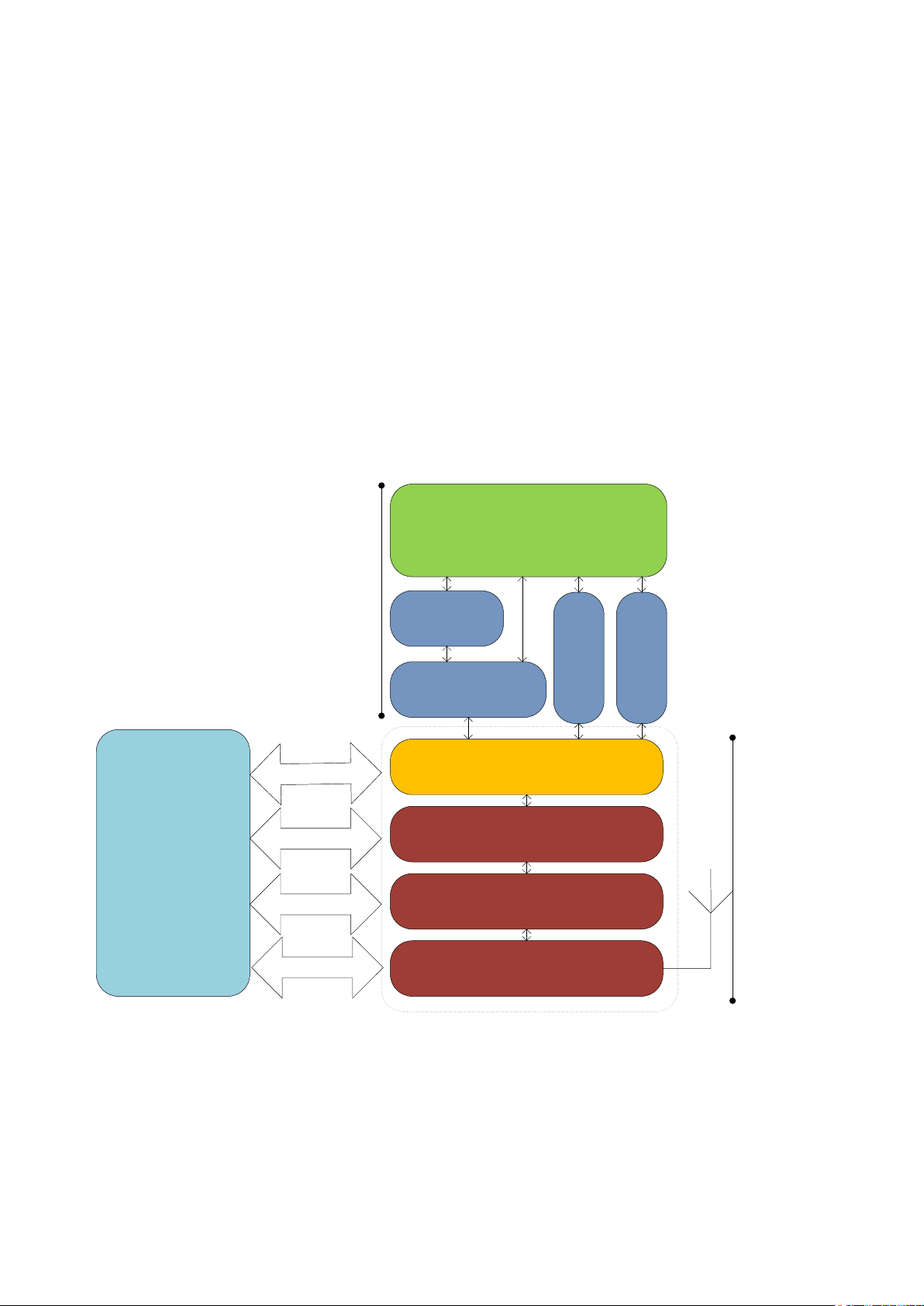
Host Controller Interface
L2CAP / eL2CAP
RFCOMM
SDP Audio
iWRAP
Link Manager
Baseband
Radio
UART / USB
GPIO / AIO
PCM / I2S / SPDIF
Analogue
Host + application
iWRAP
Hardware
1 Introduction
iWRAP is an embedded firmware running entirely on the RISC processor of WT12, WT11, WT41 and WT32
modules. It implements the full Bluetooth protocol stack and many Bluetooth profiles as well. All software
layers, including application software, run on the internal RISC processor in a protected user software
execution environment known as a Virtual Machine (VM).
The host system can interface to iWRAP firmware through one or more physical interfaces, which are also
shown in the figure below. The most common interfacing is done through the UART interface by using the
ASCII commands that iWRAP firmware supports. With these ASCII commands, the host can access Bluetooth
functionality without paying any attention to the complexity, which lies in the Bluetooth protocol stack. GPIO
interface can be used for event monitoring and command execution. PCM, SPDIF, I2S or analog interfaces
are available for audio. The available interfaces depend on the used hardware.
The user can write application code to the host processor to control iWRAP firmware using ASCII commands
or GPIO events. In this way, it is easy to develop Bluetooth enabled applications.
On WT32 there is an extra DSP processor available for data/audio processing.
Figure 1: iWRAP Bluetooth stack
Silicon Labs
Page 10 of 270
Page 11

21.4.2015
In the figure above, a Bluetooth module with iWRAP firmware could be connected to a host system for
example through the UART interface. The options are:
If the host system has a processor, software can be used to control iWRAP by using ASCII based
commands or GPIO events.
If there is no need to control iWRAP, or the host system does not need a processor, iWRAP can be
configured to be totally transparent and autonomous, in which case it only accepts connections or
automatically opens them.
GPIO lines that Bluegiga’s Bluetooth modules offer can also be used together with iWRAP to achieve
additional functionality, such as Carrier Detect or DTR signaling.
Audio interfaces can be used to transmit audio over a Bluetooth link.
Silicon Labs
Page 11 of 270
Page 12

21.4.2015
WRAP THOR AI (5.0.2 build 992)
Copyright (c) 2003-2013 Bluegiga Technologies Inc.
Built-in self-test error 992.10 - please contact <www.bluegiga.com/support>
No license key found or license key is wrong!
LICENSE 00112233445566778899aabbccddeeff
RESET
WRAP THOR AI (5.0.2 build 992)
Copyright (c) 2003-2013 Bluegiga Technologies Inc.
2 Migrating from previous iWRAP versions
This section only applies when upgrading from a previous version; users of new iWRAP5 modules
can ignore this.
For users upgrading to iWRAP5 from previous versions, the first consideration is that iWRAP is no longer
locked to Bluegiga’s address range of 00:07:80:xx:xx:xx, but instead uses a per-module license key. The
module will boot without the license key, and function normally, but with the radio interface completely
disabled. The following error message will be displayed:
For new modules coming from the factory (including modules with iWRAP3 or iWRAP4), the license key will
be written at the factory, and will be preserved in the “factory settings” section of the Persistent Store.
To enter a license key obtained from www.bluegiga.com/support, you can either use PSTool to write the
license to the key “Module security code” (0x025c PSKEY_MODULE_SECURITY_CODE), or use the built-in
command LICENSE, followed by a RESET command.
For writing license files in batches while upgrading stocked modules to iWRAP5, please contact
www.bluegiga.com/support.
Silicon Labs
Page 12 of 270
Page 13

21.4.2015
3 Changes from iWRAP 5.0.1
3.1 New features
SSP user confirmation auto-accept can be enabled by setting SET CONTROL CONFIG block #3 bit
#1: SET CONTROL CONFIG 2 0 0 0.
New SET PROFILE HID configuration bits #4 and #5, which allow for reception of raw HID output
reports and larger HID data channel MTU configuration.
SET CONTROL AUDIO allows routing input and output to different audio interfaces
New optional parameter for SET BT SNIFF allows automatic sniff / active mode management
3.2 Issues addressed
3.2.1 General issues
The radio power table for WT41-A and WT41-E has been adjusted to reduce the difference between
power output levels. Since the change does not affect the maximum power output, only the steps
between the minimum and maximum power level, it does not affect any radio certifications.
We have found and implemented a workaround for CSR’s S/PDIF issue with getting wrong sampling
rates. S/PDIF can be used for A2DP audio, but not for SCO audio. See IWRAP-577 in the list of
known issues
Added missing leading zeroes to SSP CONFIRM events – now iWRAP will always print 6 digits, for
example “012345” instead of “12345”. The leading zeroes are still missing from SSP PASSKEY
notification events (known issue IWRAP-579)
Command @{link_id} now works for link_ids above 9
Fixed a bug which caused link_ids above a disconnected link_id to stop working with the @
command; for example, if iWRAP had connections 0, 1 and 2, and connection #1 was disconnected,
@2 would no longer work
Fixed parts of INFO CONFIG output missing when using very low baud rates
Fixed a bug that limited the maximum number of ACL connections (unique Bluetooth devices) to 6
instead of 7 on BlueCore4-based modules (WT11i, WT12, WT41). On WT32, 6 is still the limit
Fixed PLAY command and SET CONTROL RINGTONE stopping working after a VOLUME command
was issued
Fixed SET BT PAGEMODE alternate pagemode setting threshold to count active ACLs (unique
devices connected to), not active logical links
Added missing leading zeroes to SSP CONFIRM events
Fixed a connection issue when making an L2CAP call and an RFCOMM call to a service UUID
simultaneously, and the L2CAP connection failed, which caused iWRAP to lose track of the RFCOMM
connection state, which in turn caused further SDP connections to fail
Fixed no sound issue when SPDIF or I2S is used as an audio input.
3.2.2 A2DP profile issues
Fixed a memory leak in the stream endpoint discovery subroutines, which caused iWRAP to crash
after 15 outgoing A2DP calls
Silicon Labs
Page 13 of 270
Page 14

21.4.2015
Fixed a bug in SET CONTROL CODEC that would leave aptX enabled for incoming connections even
when it was disabled with SET CONTROL CODEC
Fixed problem with A2DP streaming using AptX codec from some new mobile phones
3.2.3 HID profile issues
Added missing Bluetooth HID Handshake response to SET_REPORT packets sent by the HID Host
Fixed an issue with losing characters in ASCII keyboard mode when the same letter was sent over
and over again, but with different Shift key states, e.g. “AaAaAa”
HID GET now prints the last byte of an odd-numbered HID descriptor correctly; previously it always
printed the last byte as zero, even though it was stored and sent over the air correctly
Fixed HID failure in data mode when SET CONTROL ESCAPE was disabled
3.2.4 iAP profile issues
Fixed a rare data duplication bug
Fixed iAP not working with SET CONTROL CONFIG 0040 0000 (print “OK” after each command)
Fixed a bug with iWRAP hanging in MUX mode when an iAP link was abnormally disconnected in the
middle of receiving a MUX frame from the UART that was intended for the iAP link
3.3 Newly discovered known issues
See issues IWRAP-159, IWRAP-533, IWRAP-535, IWRAP-550, IWRAP-574, IWRAP-577, IWRAP-578,
IWRAP-579, IWRAP-596, IWRAP-614, IWRAP-619, IWRAP-620, IWRAP-628, IWRAP-641, IWRAP-644,
IWRAP-646, IWRAP-663, IWRAP-691, IWRAP-706, IWRAP-765 in Chapter 13.
Silicon Labs
Page 14 of 270
Page 15
21.4.2015
4 Getting started
To start using iWRAP firmware, you can use, for example, terminal software such as HyperTerminal. When
using the terminal software, make sure that the Bluetooth module is connected to your PC’s serial port. By
default, iWRAP uses the following UART settings:
Baud rate: 115200bps
Data bits: 8
Stop bits: 1
Parity bit: No parity
HW Flow Control: Enabled
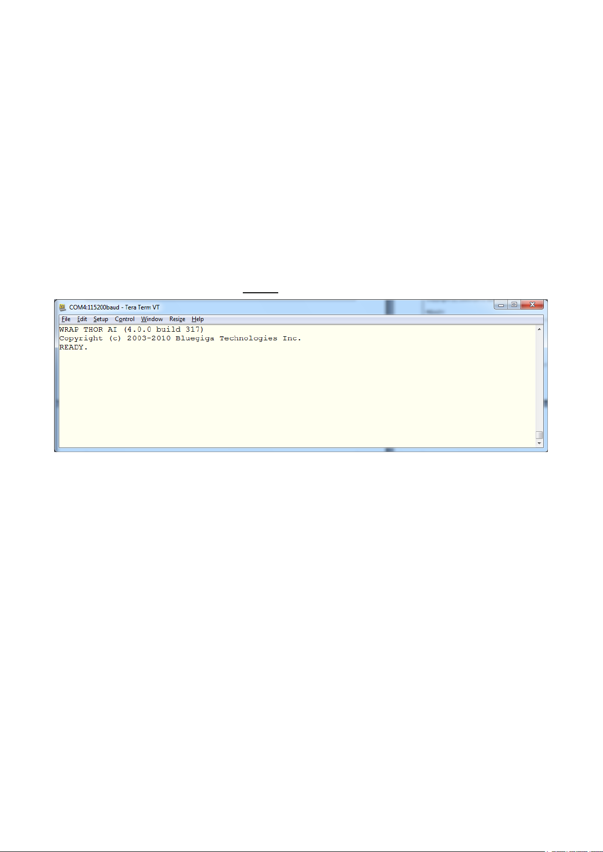
When you power up your Bluetooth module or evaluation kit, you can see the boot prompt appear on the
screen of the terminal software. After the “READY.” event iWRAP firmware is ready to be used.
Figure 2: iWRAP boot prompt
If no READY. event is received the possible reasons are:
The Bluetooth module is not equipped with iWRAP firmware, but HCI firmware
The UART logic levels are incorrect
Boot prompt is disabled with “SET CONTROL ECHO 0” setting
Silicon Labs
Page 15 of 270
Page 16

21.4.2015
AT
OK
SET
SET BT BDADDR 00:07:80:ff:ff:f1
SET BT NAME WT32-A
SET BT CLASS 001f00
SET BT IDENT BT:47 f000 4.0.0 Bluegiga iWRAP
SET BT LAP 9e8b33
SET BT PAGEMODE 4 2000 1
SET BT POWER 0 0 0
SET BT ROLE 0 f 7d00
SET BT SNIFF 0 20 1 8
SET BT MTU 667
SET CONTROL BAUD 115200,8n1
SET CONTROL CD 00 0
SET CONTROL ECHO 7
SET CONTROL ESCAPE 43 00 1
SET CONTROL GAIN 8 8
SET CONTROL MSC DTE 00 00 00 00 00 00
SET CONTROL READY 00
SET PROFILE SPP Bluetooth Serial Port
SET
4.1 First course to iWRAP
A few very basic iWRAP usage examples are presented below. Just a few very basic use cases are shown
and more detailed examples will be presented later in this user guide.
AT command can be sent to iWRAP to test that the firmware is operational. An OK response tells that iWRAP
is functional.
SET command displays the settings of the local Bluetooth device.
Silicon Labs
Page 16 of 270
Page 17

21.4.2015
INQUIRY 5
INQUIRY_PARTIAL 00:21:86:35:c9:c8 02010c
INQUIRY_PARTIAL 00:07:80:93:d7:66 240408
INQUIRY_PARTIAL a8:7b:39:c3:ca:99 5a020c
INQUIRY 3
INQUIRY 00:21:86:35:c9:c8 02010c
INQUIRY 00:07:80:93:d7:66 240408
INQUIRY a8:7b:39:c3:ca:99 5a020c
SET BT AUTH * 0000
SET BT SSP 3 0
CALL 00:07:80:93:d7:66 1101 RFCOMM
CALL 0
CONNECT 0 RFCOMM 1
SET RESET
WRAP THOR AI (4.0.0 build 317)
Copyright (c) 2003-2010 Bluegiga Technologies Inc.
READY.
INQUIRY command can be used to discover other visible Bluetooth devices in the range. An
INQUIRY_PARTIAL event is generated as soon as a device is discovered and finally is summary is displayed.
SET commands can be used to modify the settings of the local Bluetooth device. In the example below
Bluetooth PIN code required for pairing is set to “0000” and also the Secure Simple Pairing (SSP) “just works”
mode is enabled. The settings are stored on a local non-volatile memory so they need to be configured only
once. With iWRAP5 SSP is always enabled to fulfil Bluetooth 2.1 and later specifications.
A Bluetooth connection is opened with a CALL command. A CALL event indicates that a connection
establishment is in progress and a CONNECT event indicates a successful connection.
A SET RESET command can be used to return the factory level settings. iWRAP is reset as indicated by the
boot prompt.
Silicon Labs
Page 17 of 270
Page 18

21.4.2015
- CONNECT event
- RING event
- Escape sequence
- SELECT command
Command
Mode
Data Mode
- NO CARRIER event
- Escape sequence
- DTR switch
5 iWRAP modes
iWRAP has two basic operational modes, command mode and data mode. In command mode, ASCII
commands can be given to iWRAP firmware to perform various actions or to change configuration settings.
Command mode is the default mode when there are no Bluetooth connections. Data mode, on the other hand,
is used to transmit and receive data over a Bluetooth link. Data mode is only available if there is a Bluetooth
connection. It is possible to switch between modes at any time assuming the conditions for data mode are
fulfilled. The mode transitions are illustrated below.
Figure 3: Mode transitions
Silicon Labs
Page 18 of 270
Page 19

21.4.2015
Initial mode
Target mode
Requirements for state transition
Command Mode
(no Bluetooth connections)
In this mode, ASCII commands
can be given to iWRAP.
Data Mode
A connection is successfully created by
using the CALL command and
CONNECT event indicating that a
successful connection is received.
A remote device opens a Bluetooth
connection to iWRAP. A RING event
indicating that a connection is received.
If iWRAP events are disabled the carrier
detect (CD) pin can also be used to
indicate data or command mode.
Data Mode
In this mode, all data is sent
transparently from UART
interface to Bluetooth connection.
Command Mode
The user switches mode by sending an
escape sequence to iWRAP firmware or
by toggling the DTR pin.
A link is terminated (closed by the remote
device or by link loss) and NO
CARRIER event is received.
Command Mode
(active connection)
In this mode, ASCII commands
can be given to iWRAP.
Data Mode
User switches the mode either by sending
an escape sequence to iWRAP firmware
or by using the SELECT command.
5.1 The escape sequence
The escape sequence causes the iWRAP firmware to toggle between command mode and data mode. The
escape sequence consists of three (3) escape characters that are defined by the SET CONTROL ESCAPE
command. By default, the escape character is ‘+’.
Do not enter any character before and/or after the escape sequence for a guard time, which is 1 second.
Furthermore, send the escape characters individually, not as a string.
With default settings, the escape sequence is:
< 1 second sleep> +++ < 1 second sleep>
When a successful state transition from data mode to command mode is made, iWRAP sends a “READY.”
event to indicate that it is ready to receive commands.
The same escape sequence or the SELECT command can be used to return to data mode.
Table 1: iWRAP mode transitions explained
Silicon Labs
Page 19 of 270
Page 20

21.4.2015
5.2 Command mode
The command mode is the default mode when iWRAP is powered up. In command mode, ASCII commands
can be entered to iWRAP to perform various functions.
Notes:
In command mode, if there are active Bluetooth connections, the data from remote devices is buffered
into iWRAP buffers.
Because of the embedded nature of iWRAP, buffering capabilities are low and only small amounts of
data can be received to buffers. The amount of data which can be buffered depends on the firmware
version and the state of iWRAP. Usually, it is around 1000 bytes, but may vary radically.
The LIST command shows active connections and the amount of buffered data.
5.3 Data mode
Data mode is the default mode when there are one or more Bluetooth connections. In data mode, all data is
sent transparently from UART interface to the Bluetooth link and vice versa.
Notes:
When iWRAP enters command mode from data mode, a “READY” event occurs, unless events are
masked away by using the “SET CONTROL ECHO” command.
The DTR pin can be used instead of the escape sequence to switch from data mode to command
mode. This allows much faster mode switching and no guard time is needed. The DTR pin can be
enabled by using the “SET CONTROL ESCAPE” command.
When enabled, the DTR line can be configured also for closing the active connection or for a reset.
The Carrier Detect (CD) pin can be used to indicate either a Bluetooth connection or data mode. The
CD pin can be enabled and configured by using the “SET CONTROL CD” command.
The “SET CONTROL BIND” command can be used in conjunction with the “SET CONTROL
ESCAPE” command to allow data-command-data mode switches with the same GPIO line; consider
in fact the following commands together: “SET CONTROL ESCAPE - 20 1” and “SET CONTROL
BIND 0 20 F SELECT 0”
Silicon Labs
Page 20 of 270
Page 21

21.4.2015
5.4 Multiplexing mode
In iWRAP version 2.1.0 and newer, there is a special mode called multiplexing mode. In this mode, iWRAP
does not have separate commands or data modes, but data, commands and events are all handled in one
single mode. There is, however, a special protocol to separate commands and events from the actual data.
This protocol must be used between the host system and iWRAP firmware.
The advantage of multiplexing mode is that several Bluetooth connections can be handled simultaneously and
there is no need to do time consuming data-command-data mode switching. However, the downside is that
the performance of iWRAP is reduced, since the firmware needs to handle the multiplexing protocol and it
causes overhead.
To learn more about multiplexing mode, see the description of the “SET CONTROL MUX” command.
5.5 HFP and HSP modes
iWRAP 2.2.0 and newer support Bluetooth Hands-Free (v.1.6) profile. This profile includes a lot of control
messaging and events, which are handled in command mode. In other words, when a HFP connection is
opened or received no state transition occurs, but iWRAP stays in command mode, where all HFP messaging
is done. Refer to HFP profile usage for more information.
5.6 OBEX mode
IWRAP4 and newer versions support Bluetooth Object Push Profile (OPP) or File Transfer Protocol (FTP)
modes. The operation in this mode is quite similar to HFP mode. For example, there are no separate
command and data modes, but iWRAP always stays in command mode. Refer to OPP and FTP profile usage
for more information.
5.7 A2DP mode
As of iWRAP3, Bluetooth Advanced Audio Distribution Profile (A2DP) is supported. This profile also includes
control messaging and events, which are handled in command mode. In other words, when an A2DP
connection is opened or received no state transition occurs, but iWRAP stays in command mode, where all
A2DP messaging is done.
5.8 AVRCP mode
As of IWRAP3, Bluetooth Audio/Video Remote Control Profile (AVRCP) is supported. This profile also
includes control messaging and events, which are handled in command mode. In other words, when an
AVRCP connection is opened or received no state transition occurs, but iWRAP stays in command mode,
where all AVRCP messaging is done.
5.9 PBAP mode
As of IWRAP4, Bluetooth Phone Book Access Profile (PBAP) is supported. This profile also includes control
messaging and events, which are handled in command mode. In other words, when a PBAP connection is
opened or received no state transition occurs, but iWRAP stays in command mode, where all PBAP
messaging is done.
Silicon Labs
Page 21 of 270
Page 22

6 Technical details
Feature
Value
MAX simultaneous ACL connections
7 (6 with WT32)
MAX simultaneous SCO connections
1
MAX data rate
550 kbps (WTxx to BT2.0 USB dongle)
500 kbps (WTxx to WTxx)
450 kbps (WTxx to BT1.1-BT1.2 device)
N/A (MUX data rate)
50 kbps (OBEX transfer)
MAX UART baud rate
1800000 bps
Typical data transmission delay
10-15ms
Minimum data transmission delay
5-10ms
Typical SCO delay
30-40ms
Typical A2DP delay (*
150-200ms
A2DP coding/encoding methods
SBC, aptX**
PIN code length
Configurable from 0 to 16 characters.
Encryption length
From 0 to 128** bits
MAX simultaneous pairings
16
MAX Friendly name length
Configurable up to 248 characters
RFCOMM Packet size
Configurable from 21 to 1009
Supported Bluetooth profiles (iWRAP5)
GAP, SPP, HFP (v.1.6 with wideband speech), HSP (v.1.2)
A2DP, AVRCP (1.3 CT, 1.0 TG), HID, DUN, DI, OPP, FTP,
HDP, PBAP and MAP.
Supported power saving modes
Sniff and deep sleep
Bluetooth QD ID
iWRAP 5.0: B019486
iWRAP 4.0: B016540
iWRAP 3.0: B014328
iWRAP 2.2.0: B012647
21.4.2015
Silicon Labs
Page 22 of 270
Page 23

21.4.2015
Secure Simple Pairing modes
Just works mode
Man-in-the-middle protection (MITM)
Out-of-Band (OOB) pairing
Echo canceling and noise reduction
Clear Voice Capture (cVc) algorithm. A licensable 3rd party
product.
Table 2: Technical details
*) Alternative coding methods (aptX, FastStream) exist to reduce the delay to 40-90ms or to improve audio
quality.
**) Custom firmware needs to be request from www.bluegiga.com/support
Silicon Labs
Page 23 of 270
Page 24

21.4.2015
7 iWRAP command reference
iWRAP can be used and controlled from the host system by sending ASCII commands through the
UART interface to iWRAP.
This section explains the iWRAP commands and their syntax. Some simple usage examples and tips
are also given.
NOTES:
The parser is not case sensitive!
iWRAP commands must end with a line feed “\n” character.
By default iWRAP does not print OK to indicate that the command has been executed, but this
feature can be separately enabled with SET CONTROL CONFIG command.
Silicon Labs
Page 24 of 270
Page 25

21.4.2015
Command:
iWRAP version:
HW version:
Short description
AUTH
iWRAP 2.2.0
ALL
Authenticates Bluetooth pairing
BER
iWRAP 2.2.0
ALL
Reads Bit Error Rate
CALL
iWRAP 2.1.0
ALL
Opens Bluetooth connections
CLOCK
iWRAP 3.0
ALL
Reads Piconet clock
CLOSE
iWRAP 2.1.0
ALL
Closes Bluetooth connections
CONNAUTH
iWRAP 4.0.0.
ALL
Authenticate incoming connections
CONNECT
iWRAP 3.0
ALL
Connects Bluetooth links
ECHO
iWRAP 2.2.0
ALL
Echoes data to Bluetooth connection
IC
iWRAP 2.2.0
ALL
Inquiry cancel
IDENT
iWRAP 3.0
ALL
Identifies a Bluetooth device
INQUIRY
iWRAP 2.1.0
ALL
Searches other Bluetooth devices
KILL
iWRAP 3.0
ALL
Kills Bluetooth connections
L2CAP
iWRAP 3.0
ALL
Sets up L2CAP psm
LIST
iWRAP 2.1.0
ALL
Lists Bluetooth connections
NAME
iWRAP 2.2.0
ALL
Does friendly name discovery
PAIR
iWRAP 3.0
ALL
Pairs with a Bluetooth device
PING
iWRAP 2.2.0
ALL
Pings a Bluetooth connection
RFCOMM
iWRAP 3.0
ALL
Sets up RFCOMM channels
RSSI
iWRAP 2.2.0
ALL
Reads RSSI of a connection
7.1 Command listings
All the available iWRAP commands are listed and briefly described in the tables below. The detailed
description of each command can be found later.
Silicon Labs
Page 25 of 270
Page 26

SCO ENABLE
iWRAP 2.2.0
ALL
Enables SCO connections
SCO OPEN
iWRAP 2.2.0
ALL
Opens SCO connection
SDP
iWRAP 2.2.0
ALL
Browse SDP records
SDP ADD
iWRAP 2.2.0
ALL
Create SDP entries
SELECT
iWRAP 2.1.0
ALL
Selects a Bluetooth connection
TEST
iWRAP 2.2.0
ALL
Enables self test modes
TESTMODE
iWRAP 2.2.0
ALL
Enables Bluetooth test mode
TXPOWER
iWRAP 2.2.0
ALL
Reads TX power level
Table 3: Commands related to Bluetooth actions
21.4.2015
Silicon Labs
Page 26 of 270
Page 27

21.4.2015
Command:
iWRAP
version:
HW version:
Short description
@
iWRAP 4.0.0.
ALL
Shortcut for “SET {link_id} SELECT”
AIO
iWRAP 4.0.0
ALL
Read AIO values
A2DP
iWRAP3.0
WT32
A2DP streaming control
AT
iWRAP 2.1.0
ALL
Attention
BATTERY
iWRAP 3.0
WT32
Reads battery level
BCSP_ENABLE
iWRAP 3.0
ALL
Enables BCSP mode
BLINK
iWRAP 5.0.0
ALL
Configures LED blinking
BOOT
iWRAP 2.2.0
ALL
Boots module into different modes
BYPASSUART
iWRAP 3.0
ALL
Enables UART bypass
DEFRAG
iWRAP 3.0
ALL
Defrags PS key storage
DELAY
iWRAP 5.0.0
ALL
Delay before executing a command
HELP
iWRAP 2.2.0
ALL
Prints help
HID GET
iWRAP 5.0.0
ALL
HID descriptor reading
HID SET
iWRAP 5.0.0
ALL
HID descriptor writing
INFO
iWRAP 2.2.0
ALL
Prints firmware information
PIO
iWRAP 3.0
ALL
Reads & Writes PIO statuses
RESET
iWRAP 2.1.0
ALL
Does a software reset
SET
iWRAP 2.1.0
ALL
Lists iWRAP configuration
SET RESET
iWRAP 3.0.0
ALL
Restores factory settings
SLEEP
iWRAP 2.2.0
ALL
Enables deep sleep
TEMP
iWRAP 3.0
ALL
Reads internal temperature sensor
Silicon Labs
Page 27 of 270
Page 28

VOLUME
iWRAP 3.0
ALL
Changes volume level
Table 4: Generic commands
21.4.2015
Silicon Labs
Page 28 of 270
Page 29

21.4.2015
Command:
iWRAP version:
HW version:
Short description
SET BT OPP
iWRAP 2.2.0
ALL
Enable OPP profile
SET BT AUTH
iWRAP 2.1.0
ALL
Set PIN code
SET BT BDADDR
iWRAP 2.1.0
ALL
Read BD_ADDR
SET BT CLASS
iWRAP 2.1.0
ALL
Set Class-of-Device
SET BT FILTER
iWRAP 5.0.0
ALL
Inquiry result filter
SET BT IDENT
iWRAP 3.0
ALL
Set DI profile data
SET BT LAP
iWRAP 2.2.0
ALL
Set inquiry access code
SET BT MTU
iWRAP 4.0.0
ALL
Configure Bluetooth connection
MTU
SET BT NAME
iWRAP 2.1.0
ALL
Change friendly name
SET BT PAGEMODE
iWRAP 2.1.0
ALL
Set page mode and timeout
SET BT PAIR
iWRAP 2.1.0
ALL
Manage pairings
SET BT PAIRCOUNT
iWRAP 4.0.0
ALL
Limit the number of stored pairings
SET BT POWER
iWRAP 2.2.0
ALL
Set TX power levels
SET BT ROLE
iWRAP 2.1.0
ALL
Set role and supervision timeout
SET BT SCO
iWRAP 5.0.0
ALL
Configure SCO audio parameters
SET BT SNIFF
iWRAP 2.2.0
ALL
Manage automatic sniff mode
SET BT SSP
iWRAP 4.0.0
ALL
Configure SSP capabilities
Table 5: Bluetooth settings related SET commands
Silicon Labs
Page 29 of 270
Page 30

21.4.2015
Command:
iWRAP
version:
HW
version:
Short description
SET CONTROL AUDIO
iWRAP 4.0.0
WT32
Configure hardware audio interfaces
SET CONTROL AUTOCALL
iWRAP 2.1.0
ALL
Manage automatic connection
control
SET CONTROL AUTOPAIR
iWRAP 5.0.0
ALL
Manage automatic pairing
SET CONTROL BATTERY
iWRAP 4.0.0.
WT32
Change battery configuration
SET CONTROL BAUD
iWRAP 2.1.0
ALL
Change UART baud rate
SET CONTROL BIND
iWRAP 2.2.0
ALL
Manage GPIO bindings
SET CONTROL CD
iWRAP 2.1.0
ALL
Manage Carrier Detect (CD) signal
SET CONTROL CODEC
iWRAP 4.0.0
WT32
Configures the internal audio codec
SET CONTROL CONFIG
iWRAP 2.1.0
ALL
Manage configuration bits
SET CONTROL ECHO
iWRAP 2.1.0
ALL
Manage echo mode
SET CONTROL GAIN
iWRAP 3.0
WT32
Manage ADC and DAC gains
SET CONTROL INIT
iWRAP 2.1.0
ALL
Manage start-up command
SET CONTROL MICBIAS
iWRAP 3,0
WT32
Control MIC bias settings
SET CONTROL MSC
iWRAP 2.2.0
ALL
Manage MSC functionality
SET CONTROL MUX
iWRAP 2.2.0
ALL
Manage MUX mode
SET CONTROL PCM
iWRAP 3.0-4.0
ALL
Manage PCM settings. Removed in
iWRAP5.
SET CONTROL PIO
iWRAP 5.0.0
ALL
Sets the initial direction of the PIOs
SET CONTROL PREAMP
iWRAP 4.0
WT32
Enable/disable 20dB preamplifier
SET CONTROL RINGTONE
iWRAP 4.0
All
Set HFP/HSP ringtone
SET CONTROL READY
iWRAP 4.0
All
Tells when iWRAP firmware is ready
SET CONTROL VOLSCALE
iWRAP 5.0.0
WT32
Scale the volume levels
Silicon Labs
Page 30 of 270
Page 31

SET CONTROL VREGEN
iWRAP 3.0
WT32
Manage VREG_EN functionality
Table 6: Module configuration related SET commands
21.4.2015
Silicon Labs
Page 31 of 270
Page 32

21.4.2015
Command:
iWRAP version:
HW version:
Short description
SET {link_id} ACTIVE
iWRAP 2.1.0
ALL
Disable Bluetooth link power saving
SET {link_id} MASTER
iWRAP 2.1.0
ALL
Set Bluetooth link to master
SET {link_id} MSC
iWRAP 2.2.0
ALL
Set Bluetooth link MSC status
SET {link_id} PARK
only iWRAP 2.2.0
ALL
Enable Park state on a Bluetooth link
SET {link_id} SELECT
iWRAP 3.0
ALL
Set Bluetooth link to active status
SET {link_id} SLAVE
iWRAP 2.1.0
ALL
Set Bluetooth link to slave
SET {link_id} SNIFF
iWRAP 2.1.0
ALL
Enable Sniff mode on a Bluetooth link
Table 7: Bluetooth connection related SET commands
Silicon Labs
Page 32 of 270
Page 33

21.4.2015
Command:
iWRAP version:
HW version:
Short description
SET PROFILE A2DP
iWRAP 3.0.0
WT32
Enable / disable A2DP profile
SET PROFILE BGIO
iWRAP 4.0.0.
ALL
Enable / disable BGIO profile
SET PROFILE HDP
iWRAP 4.0.0
All but WT32
Enable / disable HDP profile
SET PROFILE HFP
iWRAP 2.1.0
ALL
Enable / disable HFP profile
SET PROFILE HFPAG
iWRAP 2.1.0
ALL
Enable / disable HFP profile (AG)
SET PROFILE HID
iWRAP 3.0
ALL
Enable / disable HID profile
SET PROFILE HSP
iWRAP 4.0.0
ALL
Enable / disable HSP profile
SET PROFILE OPP
iWRAP 3.0.0
ALL
Enable / disable OPP profile
SET PROFILE OTA
iWRAP 3.0.0
ALL
Enable / disable OTA profile
SET PROFILE PBAP
iWRAP 4.0.0
ALL
Enable / disable PBAP profile
SET PROFILE SPP
iWRAP 2.1.0
ALL
Enable / disable SPP profile
Table 8: Supported Bluetooth profile commands
*) HDP capable firmware only
Silicon Labs
Page 33 of 270
Page 34

7.2 List of changes from iWRAP 4
iWRAP4
iWRAP5
Short description
-
BLINK
New command BLINK
allows generation of square
wave for example to blink a
LED.
BYPASSUART
Command removed
CONNAUTH connection types:
L2CAP == 0
RFCOMM == 1
CONNAUTH connection type
parameters changed
L2CAP == 2
RFCOMM == 3
New connection types for
CONNAUTH
-
DELAY
New command to allow
delay before executing a
command.
ECHO supports only ASCII
command and always appends
\r\n at the end of the message
ECHO command can have binary data
as payload and \r\n can be removed
with SET CONTROL CONFIG
L2CAP can have only 2-4 digit
PSMs
L2CAP can have only 2 digit PSMs
In iWRAP5 the L2CAP PSM
is 2 digit only.
SET
SET
SET BT
SET CONTROL
SET PROFILE
In iWRAP it is possible to
print a subset of the full SET
listing
-
SET BT BDADDR
New command for reading
local the Bluetooth address
without need to parse the
output of the SET
command.
21.4.2015
Silicon Labs
Page 34 of 270
Page 35

21.4.2015
-
SET BT FILTER
New command
SET BT IDENT allowed
modifications only to the
description field.
SET BT IDENT allows replacing of the
Bluegiga vendor information with
customer VID received from USB
Implementer’s forum
SET BT PAGEMODE has 3
parameters
SET BT PAGEMODE has 5
parameters
In iWRAP5 it is possible to
set the page mode to
change depending on the
amount of connections the
module has. Backwards
compatible.
-
SET BT PAIR
Issuing SET BT PAIR
without parameters prints
list of pairings. This is more
practical way to parse
existing pairings than
reading the SET command
SET BT PAIR prints link key bytes
in different order than what
Frontline Air sniffer software
expects.
SET BT PAIR prints in the exact same
byte ordering as Frontline software
expect.
The byte ordering was
reversed to streamline the
sniffing procedure.
-
SET BT SCO
New command for
configuring the SCO audio
connection parameters
SET CONTROL AUDIO has 4
parameters
SET CONTROL AUDIO has 6
parameters
New optional parameters for
indicating A2DP streaming
with GPIO and for keeping
the DSP always turned on.
-
SET CONTROL AUTOPAIR
New command
SET CONTROL CD has 2
parameters
SET CONTROL CD has 3 parameters
In iWRAP5 it is possible to
have separate IOs for
indicating connection
existence and whether the
module is in data mode or
not.
Silicon Labs
Page 35 of 270
Page 36

21.4.2015
SET CONTROL ECHO has 3 bits
to configure
SET CONTROL ECHO has 4 bits to
configure
In iWRAP5 it is possible to
disable printing of SYNTAX
ERROR messages.
SET CONTROL MSC has 7
parameters
SET CONTROL MSC has 8
parameters
In iWRAP5 it is possible to
use optional RESET
parameter for reseting the
IO states after SPP
connection disconnects.
-
SET CONTROL PIO
Initial configuration for the
PIO direction and bias.
SET CONTROL PCM
Command removed
In iWRAP5 the
configuration of PSkey
PCM_CONFIG32 needs to
be done using PStool
application.
-
SET CONTROL VOLSCALE
New command
SET PROFILE HID ON
SET PROFILE HID has several
parameters
In iWRAP5 it is possible to
configure which HID
descriptors are available. In
iWRAP4 it was always
keyboard and mouse that
where enabled. Note: Not
backwards compatible
syntax.
SSP can be disabled using SET
BT SSP command
SSP always enabled. SET BT SSP
will result default setting which is SET
BT SSP 3 0
It is not possible to disable
Secure Simple Pairing in
iWRAP5. Legacy pairing is
supported with devices
which are Bluetooth 2.0 or
lower.
If SSP and PIN code are disabled
connections can be unecrypted.
Connections between iWRAP and any
BT 2.1 device or above are always
encrypted.
It is not possible to disable
Secure Simple Pairing in
iWRAP5. Legacy pairing is
supported with devices
which are Bluetooth 2.0 or
lower.
Silicon Labs
Page 36 of 270
Page 37

21.4.2015
If SSP and PIN code are disabled
connections can be created
without pairing.
Connections between iWRAP and any
BT 2.1 device or above create a
pairing.
It is not possible to disable
Secure Simple Pairing in
iWRAP5. Legacy pairing is
supported with devices
which are Bluetooth 2.0 or
lower.
Added SSPAUTH event
Occurs when SSP pairing is
attempted and CONNAUTH
events are enabled in SET
CONTROL CONFIG
ERROR CODE
ERROR CODE
Error codes in general
are different between
iWRAP4 and iWRAP5
NO CARRIER {link_id} ERROR
406 RFC_CONNECTION_FAILED
NO CARRIER {link_id} ERROR c01
RFC_L2CAP_CONNECTION_FAILED
Error code changed
NO CARRIER {link_id} ERROR
409
RFC_ABNORMAL_DISCONNECT
NO CARRIER {link_id} ERROR c0c
RFC_L2CAP_LINK_LOSS
Error code changed
NO CARRIER {link_id} ERROR
415
RFC_DLC_ALREADY_EXISTS
NO CARRIER {link_id} ERROR 1407
RFC_CHANNEL_ALREADY_EXISTS
Error code changed
Silicon Labs
Page 37 of 270
Page 38

7.3 Typographical conventions
Synopsis
COMMAND {required parameter} [optional parameter] STATIC TEXT
[2ND OPTIONAL PARAMETER]
Description
parameter
Description
Response
RESPONSE {parameters}
parameter
Description
Event
EVENT
Description
List format
COMMAND {required parameter} [optional parameter]
iWRAP COMMAND
iWRAP COMMAND RESPONSE(S)
The ASCII commands and their usage are further described in this chapter.
Commands and their output synopsis are presented as follows:
Command parameters, on the other hand, are described like this:
21.4.2015
Responses to the command are described as shown in the table below:
Events generated by commands or actions are described as follows:
The list format shows how the current command configuration appears after the SET command is
issued:
Finally, examples shown are described like this:
Silicon Labs
Page 38 of 270
Page 39

21.4.2015
Synopsis:
@ {link_id} {command}
Description:
link_id
Numeric connection identifier
{command}
Command to send to the parser
Response:
None.
CALL a8:7b:39:c3:ca:99 111F HFP (HFP connection establishment)
CALL 0
CONNECT 0 HFP 3
HFP 0 BSRF 491
HFP 0 STATUS "battchg" 5
HFP 0 STATUS "signal" 5
HFP 0 STATUS "service" 1
HFP 0 STATUS "call" 0
HFP 0 STATUS "callsetup" 0
HFP 0 STATUS "callheld" 0
HFP 0 STATUS "roam" 0
HFP 0 READY
7.4 @
Command @ can be used to read send commands to a dedicated profile parser like Hands-Free
Profile’s AT-command parser.
7.4.1 Syntax
7.4.2 Examples
Silicon Labs
Page 39 of 270
Page 40

21.4.2015
RING 1 a8:7b:39:c3:ca:99 SCO
HFP 0 VOLUME 5
HFP 0 VOLUME 5
HFP 0 VOLUME 5
HFP 0 VOLUME 5
HFP 0 VOLUME 5
HFP 0 NETWORK "elisa"
NO CARRIER 1 ERROR 113 HCI_ERROR_OETC_USER
@0 ATD777; (“ATD777;” sent to link ID 0)
HFP 0 OK
HFP 0 STATUS "callsetup" 2
RING 1 a8:7b:39:c3:ca:99 SCO
HFP 0 VOLUME 6
HFP 0 VOLUME 5
HFP 0 STATUS "callsetup" 3
The above example shows how @ command can be used to send an AT command to the HFP profile
parser. @ command replaces “SET {link_id} SELECT” command and simplifies the software
implementation in multi-profile use cases.
Silicon Labs
Page 40 of 270
Page 41

21.4.2015
Synopsis:
AIO {source}
Description:
source
Source AIO to read.
Valid values: 0 = AIO0 on WT32
1 = AIO1 on all except WT12
4 = Internal voltage reference
Response:
AIO {source} {value}
source
Source AIO to read
value
Value of the AIO
AIO 0
AIO 0 0015
7.5 AIO
Command AIO can be used to read the value of ADC converters. WT12 does not have any AIO pins,
WT32 has AIO0 and AIO1, all other modules have AIO1.
7.5.1 Syntax
7.5.2 Examples
Silicon Labs
Page 41 of 270
Page 42

21.4.2015
Synopsis
AT
Response
OK
AT
OK
SET BT AUTH * 4564\r\nAT\r\n
OK
7.6 AT
Command AT, "attention", can be used to check that iWRAP is functional and in command mode.
7.6.1 Syntax
7.6.2 Examples
Tip:
In iWRAP3 or older version iWRAP commands do not produce replies telling that command
was successful or execution has finished. AT command can be used to provide this
functionality, but appending AT into the end of other iWRAP commands.
Appending AT after “SET BT AUTH” command:
Silicon Labs
Page 42 of 270
Page 43

21.4.2015
Synopsis:
AUTH {bd_addr} [pin_code]
Description:
bd_addr
Bluetooth device address of the remote device
pin_code
Bluetooth pin code
Response:
No response
Events:
PAIR {bd_addr}
{link_key}
This event occurs if PAIR event is enabled with SET CONTROL CONFIG and
pairing is successful.
AUTH 00:07:80:81:66:8c?
AUTH 00:07:80:81:66:8c 6666
AUTH 00:07:80:81:66:8c?
AUTH 00:07:80:81:66:8c
AUTH 00:07:80:81:66:8c?
AUTH 00:07:80:81:66:8c 6666
PAIR 00:07:80:81:66:8c 0 16b9515e878c39ed785ba4499322079e
7.7 AUTH
AUTH command can be used to reply to AUTH event to perform interactive pairing. AUTH event is only
displayed if SET CONTROL CONFIG bit 11 is set.
7.7.1 Syntax
7.7.2 Examples
Interactive pairing with AUTH command, initiated from remote device.
Declining pairing with AUTH command.
Pairing with AUTH command and with PAIR event enabled.
Silicon Labs
Page 43 of 270
Page 44

21.4.2015
Synopsis
AVRCP PDU {PDU_ID} [parameters]
Description
10
Get capabilities command. Query for events or Company_ID’s the Target
supports.
Parameters:
2
Query supported Company_ID’s.
3
Query supported events.
11
List player application settings. No parameters.
12
List possible values for a player application setting.
Parameters:
{setting_id}
See list at the end of this command’s description.
13
Get current values of player application settings.
Parameters:
{number of settings}
Number of following parameters.
Followed by:
{setting_id}
See list at the end of this command’s description.
14
Set current values of player application settings.
Parameters:
{number of settings}
Number of setting_id-value-pairs that follow.
7.8 AVRCP PDU
AVRCP PDU command is used by the AVRCP Controller to send metadata request Protocol Data Units
to the Target.
7.8.1 Syntax
Silicon Labs
Page 44 of 270
Page 45

21.4.2015
Followed by:
{setting_id} {value}
See list at the end of this command’s description.
20
Get attributes of the currently playing track.
Parameters:
{number of attributes}
Number of attributes that follow. If zero, list all available
information.
Followed by (unless number of attributes is zero):
[attribute_id]
See list at the end of this command’s description.
30
Get the playing status, length and position of the current track. No parameters.
31
Register notification of events. This will request the Target to notify us when a
track is changed for instance.
Parameters:
{event_id}
See list at the end of this command’s description.
Events
AVRCP {PDU_ID name}_RSP [parsed data]
AVRCP RSP PDU_ID {PDU_ID}, data: [unparsed data]
AVRCP {PDU_ID name}_RSP REJ
Silicon Labs
Page 45 of 270
Page 46

7.8.2 Examples
AVRCP PDU 10 3
AVRCP GET_CAPABILITIES_RSP EVENT COUNT 3 PLAYBACK_STATUS_CHANGED
TRACK_CHANG
ED PLAYBACK_POSITION_CHANGED
AVRCP PDU 11
AVRCP LIST_APPLICATION_SETTING_ATTRIBUTES_RSP COUNT 2 REPEAT SHUFFLE
AVRCP PDU 12 2
AVRCP LIST_APPLICATION_SETTING_VALUES_RSP COUNT 3 1 2 3
AVRCP PDU 13 1 2
AVRCP GET_APPLICATION_SETTING_VALUE_RSP COUNT 1 REPEAT OFF
AVRCP PDU 14 1 2 2
AVRCP SET_APPLICATION_SETTING_VALUE_RSP
AVRCP PDU 13 1 2
AVRCP GET_APPLICATION_SETTING_VALUE_RSP COUNT 1 REPEAT SINGLE_TRACK
AVRCP PDU 20 2 1 2
AVRCP GET_ELEMENT_ATTRIBUTES_RSP COUNT 2 TITLE “Cold Women and Warm Beer”
ARTIST “The Black League”
AVRCP PDU 31 1 1
AVRCP REGISTER_NOTIFICATION_RSP INTERIM PLAYBACK_STATUS_CHANGED PLAYING
(the interim response is received right after the request to confirm we were registered for notification)
AVRCP REGISTER_NOTIFICATION_RSP CHANGED PLAYBACK_STATUS_CHANGED PAUSED
(the changed response is received when the playing status changes)
Ask the Target which events it supports.
Ask the Target about its player application settings, their possible values and change a value.
21.4.2015
Ask the Target about the title and artist of the song that is currently playing and ask it to notify us if the
playback status changes.
Silicon Labs
Page 46 of 270
Page 47

21.4.2015
Synopsis:
BATTERY
Description:
None
Response:
None
Events:
BATTERY {mv}
Current battery voltage in millivolts.
BATTERY
BATTERY 3673
7.9 BATTERY
Command BATTERY is used to read the current voltage of the module battery. Works only with WT32.
7.9.1 Syntax
7.9.2 Examples
Reading battery voltage.
Silicon Labs
Page 47 of 270
Page 48

21.4.2015
Synopsis:
BCSP_ENABLE
Description:
None
Response:
No response
Events:
None
BCSP_ENABLE
À
?¯WWUo`À
?¯WWUo`À
?¯WWUo`À
?¯WWUo`À
7.10 BCSP_ENABLE
Command BCSP_ENABLE is used to boot the device and enter BCSP mode; it is an alias for BOOT 1.
See the documentation of BOOT command for a detailed explanation of iWRAP boot modes.
7.10.1 Syntax
7.10.2 Examples
Switching iWRAP into BCSP mode. BCSP link establishment packets are sent after command has been
executed.
Silicon Labs
Page 48 of 270
Page 49

7.11 BER
Synopsis:
BER {link_id}
Description:
link_id
Numeric connection identifier
Response:
BER {bd_addr} {ber}
bd_addr
Bluetooth address of the remote device
ber
Average Bit Error Rate on the link. Possible values are from 0.0000 to 100.0000.
Events:
None
LIST
LIST 1
LIST 0 CONNECTED RFCOMM 320 0 0 3 8d 8d 00:60:57:a6:56:49 1 OUTGOING ACTIVE MASTER
PLAIN
BER 0
BER 00:60:57:a6:56:49 0.0103 (Bit Error Rate is 0.0103 per cent)
The BER command returns the Bit Error Rate of the given link ID.
7.11.1 Syntax
21.4.2015
7.11.2 Examples
Checking the Bit Error Rate of an active connection.
Note:
Works only for BDR links.
Silicon Labs
Page 49 of 270
Page 50

21.4.2015
Synopsis:
BLINK [{pio_mask} {off_time} {on_time}]
Description:
pio_mask
Pio mask for IOs that BLINK command should control.
off_time
Defines how long time the IO stays low per period. Hex value, unit is ms.
100 (hex) = 256(dec) ms
on_time
Defines how long time the IO stays high per period. Hex value, unit is ms.
100 (hex) = 256(dec) ms
Response:
No response
Disable:
BLINK
Events:
None
BLINK 80 100 100
7.12 BLINK
Blink command allow generation of periodic square wave which can be used for example for driving a
LED. The timings are not complitely accurate an some jitter may occur.
7.12.1 Syntax
7.12.2 Examples
Sets the PIO7 to stay low for 256ms and then high for 256ms. The process continues until BLINK
command is issued without parameters.
Silicon Labs
Page 50 of 270
Page 51

21.4.2015
Synopsis:
BOOT {boot_mode}
Description:
boot_mode
0000
iWRAP
0001
HCI, BCSP, 115200,8E1
0003
HCI, USB
0004
HCI, H4, 115200,8N1
Response:
No response
BOOT 1
•Ò•¯WWUo`À
•Ò•¯WWUo`À
•Ò•¯WWUo`À
•Ò•¯WWUo`À
7.13 BOOT
The BOOT command is used to temporarily restart the module so that it will operate in one of the HCI
modes.
After issuing this command, the module will immediately enter the selected HCI mode. After a reset, the
module will boot in iWRAP mode again.
The boot mode change can be made permanent by writing the boot mode to PS-key: “Initial device
bootmode”. See chapter “Switching between iWRAP and HCI firmware”
7.13.1 Syntax
7.13.2 Examples
Boot to BCSP mode. Same as issuing BCSP_ENABLE command.
Silicon Labs
Page 51 of 270
Page 52

21.4.2015
Synopsis
CALL {address} {target} {connect_mode} [MTU {payload size}]
Description
address
Bluetooth address of the remote device
target
RFCOMM, HFP or HFP-AG, HID or A2DP target for the connection. The target
can be one of the following:
channel
RFCOMM channel number
HFP channel number
HFP-AG channel number
Format: xx (hex)
uuid16
16-bit UUID for searching channel
Format: xxxx (hex)
uuid32
32-bit UUID for searching channel
Format: xxxxxxxx (hex)
uuid128
128-bit UUID for searching channel
Format: xxxxxxxx-xxxx-xxxx-xxxx-xxxxxxxxxxxx (hex)
L2CAP psm
16-bit L2CAP psm. Must be an odd value.
Format: xxxx (hex)
connect_mode
Defines the connection mode to be established.
Possible modes are:
7.14 CALL
The CALL command is used to initiate Bluetooth connections to the remote devices. Connections are
closed by using command CLOSE. Currently open connections can be viewed by using command
LIST.
7.14.1 Syntax
Silicon Labs
Page 52 of 270
Page 53

RFCOMM
Normal RFCOMM connection
HFP
Opens a connection in the Hands Free device mode.
HFP-AG
Opens a connection in the Hands Free Audio Gateway mode.
A2DP
Opens a connection in the Advanced Audio Distribution Profile (A2DP)
mode. L2CAP psm for A2DP is 19.
AVRCP
Opens a connection in the Audio Video Remote Control Profile (AVRCP)
mode. L2CAP psm for AVRCP is 17.
HID
Opens a connection in the HID keyboard mode or HID mouse mode.
L2CAP psm for HID is 11.
L2CAP
Opens a generic L2CAP connection.
PBAP
Opens a Phone Book Access Profile connection.
OPP
Opens an OBEX Object Push Profile connection.
FTP
Opens an OBEX File Transfer Profile connection.
HSP
Opens a Bluetooth Headset Profile connection
HSP-AG
Opens a Bluetooth Headset Profile Audio Gateway connection
HDP
Opens a Bluetooth Health Device Profile connection
MTU
Indicates that the default MTU value will be overridden.
payload size
Payload size to use in bytes. Range: 21 to 1009.
21.4.2015
Silicon Labs
Page 53 of 270
Page 54

21.4.2015
Response
CALL {link_id}
link_id
Numeric connection identifier
Events
CONNECT
Delivered if the CALL command is successful.
NO CARRIER
Delivered if the CALL command fails.
PAIR
If the PAIR event is enabled by using “SET CONTROL CONFIG”, it will be
displayed during the call if paring has to be done.
CLOCK
If piconet clock event is enabled, CLOCK event will be displayed.
AUTH
If interactive pairing mode is enabled and no paring exists, AUTH event will be
displayed.
CALL 00:07:80:80:52:27 1101 RFCOMM
CALL 0
CONNECT 0 RFCOMM 1
CALL 00:07:80:80:52:27 1 RFCOMM
CALL 0
CONNECT 0 RFCOMM 1
CALL 00:07:80:80:52:26 1101 RFCOMM
CALL 0
NO CARRIER 0 ERROR 406 RFC_CONNECTION_FAILED
7.14.2 Examples
Creating a successful connection to 00:07:80:80:52:27 using Serial Port Profile.
(UUID16 SPP = 1101)
Creating a successful connection to 00:07:80:80:52:27 using RFCOMM channel 1.
Unsuccessful SPP connection attempt to 00:07:80:80:52:26.
Silicon Labs
Page 54 of 270
Page 55

Creating a successful connection to 00:07:80:80:52:27 with MTU 600.
CALL 00:07:80:80:52:27 1 RFCOMM MTU 600
CALL 0
CONNECT 0 RFCOMM 1
CALL 00:07:80:80:52:27 19 A2DP
CALL 0
CONNECT 0 A2DP 19
CONNECT 1 A2DP 19
CALL 00:07:80:80:52:27 17 AVRCP
CALL 0
CONNECT 0 AVRCP 17
CALL 00:07:80:80:52:27 11 HID
CALL 0
CONNECT 0 HID 11
CONNECT 1 HID 13
CALL 00:07:80:80:52:27 112F PBAP
CALL 0
CONNECT 0 PBAP 5
CALL 00:07:80:80:52:27 1105 OPP
CALL 0
CONNECT 0 OPP 2
Creating a successful A2DP connection
Creating a successful AVRCP connection
21.4.2015
Creating a successful HID connection
Creating a successful PBAP connection
Creating a successful OBEX OPP connection
Silicon Labs
Page 55 of 270
Page 56

Creating a successful Health Device Profile MCAP Communications Link (MCL)
CALL 00:07:80:80:52:27 1001 HDP
CALL 0
CONNECT 0 HDP 4097
CALL 00:07:80:80:52:27 1008 HSP
CALL 0
CONNECT 0 HSP 5
CALL 00:07:80:80:52:26 1008 HSP-AG
CALL 0
CONNECT 0 HSP-AG 5
Opening a HSP connection from iWRAP to Headset Audio Gateway (phone).
Opening a HSP connection from iWRAP (HSP-AG) to Headset.
21.4.2015
Note:
If CALL is used with CHANNEL instead of UUID, it will be on average around 300ms faster,
since there is no need to do service discovery. However when calling directly with RFCOMM
channel you need to be sure that the profile you want to connect to is always in that RFCOMM
channel. RFCOMM channel assignments are manufacturer specific and vary between different
Bluetooth devices.
Silicon Labs
Page 56 of 270
Page 57

21.4.2015
Synopsis:
CLOCK {link_id}
Description:
link_id
Numeric connection identifier
Response:
No response
Events:
CLOCK {bd_addr}
{clock}
CLOCK event occurs, if valid link_id is used.
SYNTAX ERROR
If incorrect parameters are given.
CLOCK 0
CLOCK 00:07:80:12:34:56 3bb630
7.15 CLOCK
CLOCK command can be used to read the Bluetooth Piconet clock value. This is useful if time
synchronization between different Piconet devices needs to be achieved.
7.15.1 Syntax
7.15.2 Examples
Reading Piconet clock value:
Note:
Piconet clock is extremely useful when time needs to be synchronized between Piconet slaves.
All the slaves in the Piconet are synchronized to master’s clock and they share the same clock
value.
Accuracy is 625us, but it also takes some time for the iWRAP to perform the CLOCK command
and display the result. This time can not be unambiguously defined as it depends on the state of
iWRAP.
Silicon Labs
Page 57 of 270
Page 58

7.16 CLOSE
Synopsis:
CLOSE {link_id}
Description:
link_id
Numeric connection identifier from a previously used command CALL or from event
RING.
Response:
No response
Events:
NO CARRIER
This event is delivered after the link has been closed.
CALL 00:60:57:a6:56:49 1103 RFCOMM
CALL 0
CONNECT 0 RFCOMM 1
[+++] (data mode -> command mode transition)
READY.
CLOSE 0
NO CARRIER 0 ERROR 0
Command CLOSE is used to terminate a Bluetooth connection.
7.16.1 Syntax
21.4.2015
7.16.2 Examples
Closing an active connection:
Silicon Labs
Page 58 of 270
Page 59

21.4.2015
Synopsis:
CONNAUTH {bd_addr} {protocol_id } {channel_id} [OK]
Description:
bd_addr
Bluetooth device address of the remote device trying to connect.
protocol_id
Protocol ID of the incoming connection
1
Security manager - Bonding
2
L2CAP
3
RFCOMM
channel_id
Channel number of the incoming connection. Either PSM in the case of L2CAP or
channel number in the case of RFCOMM
OK
Optional flag, which decides if the connection is accepted or not. If the flag is used
the connection is accepted and if it is not used the connection is declined.
Response:
None
Events:
None
7.17 CONNAUTH
CONNAUTH command can be used to authorize incoming Bluetooth connections. It is used to reply to
CONNAUTH events which are activated by setting the bit 4 of the optional_block_1 of the SET
CONTROL CONFIG configuration command.
7.17.1 Syntax
Silicon Labs
Page 59 of 270
Page 60

21.4.2015
CONNAUTH 00:07:80:90:f5:47 2 3? #do you accept L2CAP connection to PSM 3?
CONNAUTH 00:07:80:90:f5:47 2 3 OK
CONNAUTH 00:07:80:90:f5:47 3 1? #do you accept RFCOMM connection to channel 1?
CONNAUTH 00:07:80:90:f5:47 3 1 OK
RING 0 00:07:80:90:f5:47 1 RFCOMM #Incoming RFCOMM connection to channel 1 opened
7.17.2 Examples
Accepting incoming SPP connection requires accepting first the lower level L2CAP connection and then
the actual RFCOMM channel in which the SPP data flows.
Note:
CONNAUTH events will not be generated for connections using an authenticated (MITM-
enabled) SSP link key, because the CSR baseband controller will treat such links authenticated
by definition.
Silicon Labs
Page 60 of 270
Page 61

21.4.2015
Synopsis:
CONNECT {link_id1} {link_id2}
Description:
link_id_1
Numeric connection identifier as displayed by the LIST command.
link_id_2
Numeric connection identifier as displayed by the LIST command.
Response:
None
Events:
None
7.18 CONNECT
iWRAP can act as a repeater / range extender for RFCOMM connections by using the CONNECT
command which will transparently link two ongoing connections together as a connection between the
two remote devices.
7.18.1 Syntax
Silicon Labs
Page 61 of 270
Page 62

7.18.2 Examples
SET BT PAGEMODE 3
RING 0 00:07:80:87:69:2f 1 RFCOMM
RING 1 00:07:80:87:68:ec 1 RFCOMM
+++ (Data to command mode transition)
READY.
LIST (List active connections)
LIST 2
LIST 0 CONNECTED RFCOMM 320 0 0 33 8d 1 00:07:80:87:69:2f 1 INCOMING ACTIVE SLAVE
PLAIN 0
LIST 1 CONNECTED RFCOMM 320 0 0 31 8d 8d 00:07:80:87:68:ec 1 INCOMING ACTIVE MASTER
PLAIN 0
CONNECT 0 1
Piping two RFCOMM connections.
21.4.2015
First the page mode is set to 3 so that iWRAP is able to receive 2 connections. Second LIST command
is issued to show that two connections exist. Finally the connections are piped with CONNECT
command. After this has been done iWRAP transparently sends all data from 1st connection to the 2nd
one and vice versa.
Silicon Labs
Page 62 of 270
Page 63

21.4.2015
Synopsis:
ECHO {link_id} [string]
Description:
link_id
Numeric connection identifier
string
User-determined string of characters. Use \xx for escaping hex data. By default \r\n
is appended at the end of the string. This can be avoided by enabling SET
CONTROL CONFIG bit 12 from the optional Block 2.
Response:
No response
Events:
None
ECHO 0 DATA (Sends “DATA\r\n” to link with ID 0)
ECHO 0 DATA\00\01 (Sends “DATA\x00\x01\r\n” to link with ID 0)
7.19 ECHO
The ECHO command sends a specified string of characters to the active link specified by the ‘link_id’
parameter. This command can be used, for example, with command SET CONTROL BIND to send an
indication of activity over a Bluetooth link.
7.19.1 Syntax
7.19.2 Examples
Silicon Labs
Page 63 of 270
Page 64

21.4.2015
Synopsis:
DEFRAG
Description:
None
Response:
No response
Events:
None
7.20 DEFRAG
This command defragments persistent store memory. The command will reset iWRAP. iWRAP will run
DEFRAG during normal power up procedure if it needed. DEFRAG command forces the iWRAP to
perform defragmentation procedure even if it would not be needed.
7.20.1 Syntax
Silicon Labs
Page 64 of 270
Page 65

7.21 DELAY
Synopsis:
DELAY {id} [delay] [command]
Description:
Id
Delay timer ID. Multiple paraller DELAYs can be launched using different ids.
id range is 0-7
delay
Decimal value in ms. Delay after the command is launched.
command
Standard iWRAP command or string to be sent to the active Bluetooth link.
The maximum length for command is 31 characters.
Disable:
DELAY {id}
To disable DELAY before it is executed. Use id parameter to define the DELAY timer
that you want to cancel.
Response:
No response
List format:
DELAY {id} [delay] [command]
If no binding exists, “SET CONTROL
DELAY” will not be displayed
DELAY 0 60000 SET BT PAGEMODE 0
With DELAY, it is possible to delay execution of iWRAP commands.
7.21.1 Syntax
21.4.2015
7.21.2 Examples
Set module to pagemode 0 (Not connectable and not visible in inquiry) after 60s from DELAY command
execution.
Silicon Labs
Page 65 of 270
Page 66

21.4.2015
SET CONTROL INIT DELAY 0 60000 SET BT PAGEMODE 0
Set module to pagemode 0 (Not connectable and not visible in inquiry) after 60s from module boot.
Could be used to allow pairing during first 60s of device operation.
Silicon Labs
Page 66 of 270
Page 67

21.4.2015
Synopsis:
HID GET
Response:
HID GET {length}
{descriptor}
To disable DELAY before it is executed. Use id parameter to define the DELAY timer
that you want to cancel.
Description:
Length
Length of the descriptor. Format is a uint16 in hexadecimal format.
Descriptor
Descriptor printed as hex numbers in ASCII format. The descriptor is entire USB HID
report descriptor in hexadecimal format.
7.22 HID GET
Is used for reading HID descriptors which are visible in the HID profile SDP record. For more
information how to set up the HID profile please read the HID application note.
7.22.1 Syntax
Silicon Labs
Page 67 of 270
Page 68

21.4.2015
Synopsis:
HID SET {length} {descriptor}
Description:
Length
Length of the descriptor. Format is a uint16 in hexadecimal format.
Descriptor
Descriptor printed as hex numbers in ASCII format. The descriptor is entire USB HID
report descriptor in hexadecimal format.
Response:
7.23 HID SET
Is used to set HID descriptors which are visible in the HID profile SDP record. For more information how
to set up the HID profile please read the HID application note.
7.23.1 Syntax
Silicon Labs
Page 68 of 270
Page 69

21.4.2015
Synopsis:
INQUIRY {timeout} [NAME] [LAP {lap}]
Description:
timeout
The maximum amount of time (in units of 1.28 seconds) before the inquiry process is
halted.
Range: 1-48
NAME
Optional flag to automatically request the friendly name for found devices. See
command NAME for more information about the remote name request.
LAP
Optional flag for specifying that inquiry access code will be used.
lap
Value for inquiry access code. The following values are possible:
9E8B33
General/Unlimited Inquiry Access Code (GIAC). This is the default value
unless “SET BT LAP” is used.
9E8B00
Limited Dedicated Inquiry Access Code (LIAC).
9E8B01-9E8B32 and 9E8B34-9E8B3F
Reserved for future use.
7.24 INQUIRY
Command INQUIRY is used to find other Bluetooth devices in the area i.e. to make a device discovery.
7.24.1 Syntax
Silicon Labs
Page 69 of 270
Page 70

21.4.2015
Response:
INQUIRY {num_of_devices}
and
INQUIRY {addr} {class_of_device}
num_of_devices
The number of found devices
addr
Bluetooth device address
class_of_device
Bluetooth Class of Device
Events:
INQUIRY_PARTIAL
These events are delivered as devices are found.
INQUIRY_EXTENDED
These events are delivered when Bluetooth 2.1 + EDR devices are found that
support Extended Inquiry Response (EIR)
NAME
These events are delivered after INQUIRY if the NAME flag is present.
NAME_ERROR
These events are delivered after INQUIRY if the NAME flag is present and the
name discover fails.
INQUIRY 1
INQUIRY_PARTIAL 00:14:a4:8b:76:9e 72010c
INQUIRY_PARTIAL 00:10:c6:62:bb:9b 1e010c
INQUIRY 2
INQUIRY 00:14:a4:8b:76:9e 72010c
INQUIRY 00:10:c6:62:bb:9b 1e010c
7.24.2 Examples
Basic INQUIRY command example
Silicon Labs
Page 70 of 270
Page 71

An INQUIRY with NAME resolution
INQUIRY 1 NAME
INQUIRY_PARTIAL 00:14:a4:8b:76:9e 72010c
INQUIRY 1
INQUIRY 00:14:a4:8b:76:9e 72010c
NAME 00:14:a4:8b:76:9e "SWLTMIKKO_3"
INQUIRY 1 LAP 9E8B00
INQUIRY_PARTIAL 00:07:80:80:52:15 111111
INQUIRY_PARTIAL 00:07:80:80:52:27 111111
INQUIRY 2
INQUIRY 00:07:80:80:52:15 111111
INQUIRY 00:07:80:80:52:27 111111
INQUIRY 1
INQUIRY_PARTIAL 00:14:a4:8b:76:9e 72010c “” -71
INQUIRY_PARTIAL 00:10:c6:62:bb:9b 1e010c “” -73
INQUIRY 2
INQUIRY 00:14:a4:8b:76:9e 72010c
INQUIRY 00:10:c6:62:bb:9b 1e010c
INQUIRY 2
INQUIRY_PARTIAL 00:18:42:f1:a5:be 5a020c "" -92
INQUIRY_PARTIAL 00:17:e4:ef:f9:01 50020c "" -92
INQUIRY_EXTENDED 00:07:80:87:68:ec RAW 0909575433322d53616d020a0800
INQUIRY_PARTIAL 00:07:80:87:68:ec 200428 "WT32-Sam" -73
INQUIRY 3
INQUIRY 00:18:42:f1:a5:be 5a020c
INQUIRY 00:17:e4:ef:f9:01 50020c
INQUIRY 00:07:80:87:68:ec 200428
An INQUIRY command with LIAC in use
21.4.2015
An INQUIRY command with RSSI enabled
An INQUIRY command with EIR responses
Silicon Labs
Page 71 of 270
Page 72

7.25 IC
Synopsis:
IC
Description:
No Description
Response:
INQUIRY {num_of_devices}
INQUIRY {addr} {class_of_device}
num_of_devices
The number of found devices
addr
Bluetooth address of a found device
class_of_device
Bluetooth Class of Device of a found device
Events:
None
INQUIRY 5
INQUIRY_PARTIAL 00:14:a4:8b:76:9e 72010c “” -71
INQUIRY_PARTIAL 00:10:c6:62:bb:9b 1e010c “” -73
IC
INQUIRY 2
INQUIRY 00:14:a4:8b:76:9e 72010c
INQUIRY 00:10:c6:62:bb:9b 1e010c
The IC (inquiry cancel) command can be used to stop an on-going inquiry.
7.25.1 Syntax
21.4.2015
7.25.2 Examples
Silicon Labs
Page 72 of 270
Page 73

21.4.2015
Note:
IC command cancels the inquiry only if issued before the “INQUIRY {num_of_devices}”
message. The name resolution process can not be cancelled with IC.
Silicon Labs
Page 73 of 270
Page 74

21.4.2015
Synopsis:
IDENT {bd_addr}
Description:
bd_addr
Bluetooth device address of the remote device
Response:
No response
Events:
IDENT
IDENT event is raised if a successful response is received
IDENT ERROR
IDENT ERROR event is raised if identification fails
IDENT 00:07:80:00:a5:a5
IDENT 00:07:80:00:a5:a5 BT:47 f000 3.0.0 “Bluegiga iWRAP”
IDENT 00:07:80:82:42:d8
IDENT 00:07:80:82:42:d8 BT:47 b00b 3.2.0 “Bluegiga Access Server”
IDENT 00:07:80:00:48:84
IDENT ERROR 2 00:07:80:00:48:84 NOT_SUPPORTED_BY_REMOTE
7.26 IDENT
IDENT command can be used to identify a remote Bluetooth device with the Bluetooth Device ID profile.
7.26.1 Syntax
7.26.2 Examples
Successful IDENT of a remote Bluetooth device.
Using IDENT to try to identify a remote Bluetooth device without success.
Silicon Labs
Page 74 of 270
Page 75

7.27 INFO
Synopsis:
INFO [CONFIG | BOOTMODE]
Description:
CONFIG
Optional flag that displays more detailed information about the firmware for
example changed parameters.
BOOTMODE
Displays bootmode parameters
Response:
Information about iWRAP version and features.
Events:
None.
INFO displays information about iWRAP version and features.
7.27.1 Syntax
21.4.2015
Silicon Labs
Page 75 of 270
Page 76

7.27.2 Examples
INFO
WRAP THOR AI (4.0.0 build 313)
Copyright (c) 2003-2010 Bluegiga Technologies Inc.
Compiled on Apr 8 2010 11:23:45, running on WT32-A module, psr v26
A2DP AVRCP BATTERY FTP MAP MICBIAS PBAP PIO=0x07ff SSP SUBRATE VOLUME
- BOCK3 version 313 (Apr 8 2010 11:23:38) (max acl/sco 7/1)
- Bluetooth version 2.1, Power class 3
- Loader 6302, firmware 6302 (56-bit encryption), native execution mode
- up 0 days, 01:12, 0 connections (pool 2)
READY.
INFO CONFIG
WRAP THOR AI (4.0.0 build 313)
Copyright (c) 2003-2010 Bluegiga Technologies Inc.
Compiled on Apr 8 2010 11:23:45, running on WT32-A module, psr v26
A2DP AVRCP BATTERY FTP MAP MICBIAS PBAP PIO=0x07ff SSP SUBRATE VOLUME
- BOCK3 version 313 (Apr 8 2010 11:23:38) (max acl/sco 7/1)
- Bluetooth version 2.1, Power class 3
- Loader 6302, firmware 6302 (56-bit encryption), native execution mode
- up 0 days, 00:00, 0 connections (pool 1)
- User configuration:
&02ac = 0000 0000 002b 0000 0000 0000 0000 0000 0000 0000 0042 0000 0000 0000 0010 0000 0000
0000 0000 029b 0000 0000 0000 0000
&02ad = 5457 3233 412d
&02b1 = 0000 0000 0000
READY.
21.4.2015
Detailed information display:
Silicon Labs
Page 76 of 270
Page 77

21.4.2015
Note:
When requesting a custom firmware configuration from Bluegiga, it useful to attach output of
“INFO CONFIG” to the request.
Silicon Labs
Page 77 of 270
Page 78

7.28 KILL
Synopsis:
KILL {bd_addr} [reason]
Description:
bd_addr
Bluetooth address of the connected remote device.
reason
Reason for disconnecting the ACL link; see Chapter 9 for a listing of possible error
codes. The default value is 0x115: HCI_ERROR_OETC_POWERING_OFF, device
is about to power off.
All existing RFCOMM connections will disconnect with reason
RFC_ABNORMAL_DISCONNECT.
Response:
None
Events:
NO CARRIER
This event is delivered after the link is closed.
Command KILL is used to explicitly terminate all ACL connections between two devices.
7.28.1 Syntax
21.4.2015
Silicon Labs
Page 78 of 270
Page 79

7.29 L2CAP
Synopsis:
L2CAP {psm}
Description:
psm
L2CAP psm; must be an two digit odd number in hex.
Response:
No response
Events:
SYNTAX ERROR
If an invalid UUID is given.
L2CAP 37 (Creates L2CAP psm 37 on the local device)
CALL 00:07:80:12:34:56 37 L2CAP (Opening L2CAP connection to a remote device)
CALL 0
CONNECT 0 L2CAP 37
Command L2CAP is used to create a L2CAP psm for L2CAP connections to the local device.
7.29.1 Syntax
21.4.2015
7.29.2 Examples
Making an L2CAP call between two iWRAPs:
Silicon Labs
Page 79 of 270
Page 80

21.4.2015
Synopsis:
LICENSE {key}
Description:
key
128-bit (32 character) hexadecimal formatted license key
Response:
No response
Events:
SYNTAX ERROR
If an invalid key is given.
LICENSE 00112233445566778899aabbccddeeff
RESET
7.30 LICENSE
The LICENSE command can be used to write an iWRAP5 license key when directly interfacing to the
Persistent Store is not possible. A reset is required to take the key into use. SET RESET does not
overwrite the license key even though the license key would have been set using the LICENSE
command.
7.30.1 Syntax
7.30.2 Examples
Silicon Labs
Page 80 of 270
Page 81

21.4.2015
Synopsis:
LIST
Description:
No description
Response:
LIST {num_of_connections}
LIST {link_id} CONNECTED {mode} {blocksize} 0 0 {elapsed_time} {local_msc} {remote_msc} {addr}
{channel} {direction} {powermode} {role} {crypt} {buffer} [ERETX]
num_of_connections
Number of active connections. Possible values range from 0 to 7.
link_id
Numeric connection identifier
mode
RFCOMM
Connection type is RFCOMM
L2CAP
Connection type is L2CAP
SCO
Connection type is SCO
blocksize
RFCOMM, L2CAP or SCO data packet size, that is, how many bytes of data can
be sent in one packet
elapse_time
Link life time in seconds
local_msc
Local serial port modem status control (MSC) bits.
remote_msc
Remote serial port modem status control (MSC) bits.
addr
Bluetooth device address of the remote device
7.31 LIST
Command LIST shows the count of active connection and detailed information about each connection.
7.31.1 Syntax
Silicon Labs
Page 81 of 270
Page 82

21.4.2015
channel
RFCOMM channel or L2CAP psm number at remote device
direction
Direction of the link. The possible values are:
OUTGOING
The connection has been initiated by the local device.
INCOMING
The connection has been initiated by the remote device
powermode
Power mode for the link. The possible values are:
ACTIVE
Connection is in active mode, no power saving in use
SNIFF
Connection is in sniff mode
HOLD
Connection is in hold mode
PARK
Connection is in park mode
role
Role of the link. The possible values are:
MASTER
iWRAP is the master device of this connection
SLAVE
iWRAP is the slave device of this connection
crypt
Encryption state of the connection. The possible values are:
PLAIN
Connection is not encrypted
ENCRYPTED
Connection is encrypted
buffer
Tells the amount of data (in bytes) that is stored in the incoming data buffer.
ERETX
This flag is visible is enhanced retransmission mode is in use. At the moment
only used with HDP connections.
Events:
No events raised
Silicon Labs
Page 82 of 270
Page 83

7.31.2 Examples
LIST
LIST 1
LIST 0 CONNECTED RFCOMM 320 0 0 3 8d 8d 00:60:57:a6:56:49 1 OUTGOING ACTIVE MASTER
PLAIN 0
Listing active connections:
21.4.2015
Silicon Labs
Page 83 of 270
Page 84

7.32 NAME
Synopsis:
NAME {bd_addr}
Description:
bd_addr
Bluetooth address of the connected remote device.
Response:
NAME {bd_addr} “{name}”
or
NAME ERROR {error_code} {bd_addr} {reason}
bd_addr
Bluetooth address of the connected remote device.
name
Friendly name of the remote device
error_code
Error code
reason
ASCII description of the reason
Events:
None.
Command NAME can be used to perform a friendly name discovery.
7.32.1 Syntax
21.4.2015
Silicon Labs
Page 84 of 270
Page 85

7.32.2 Examples
NAME 00:07:80:FF:FF:F1
NAME 00:07:80:FF:FF:F1 "WT32-A"
NAME 00:07:80:FF:FF:F2
NAME ERROR 0x104 00:07:80:FF:FF:F2 HCI_ERROR_PAGE_TIMEOUT
Making a successful name discovery
Name discovery error because of page timeout
21.4.2015
Silicon Labs
Page 85 of 270
Page 86

21.4.2015
Synopsis
PAIR {bd_addr}
Description
bd_addr
Bluetooth device address of the device remote device
Response
PAIR {bd_addr} {result}
bd_addr
Bluetooth device address of the device remote device
result
OK
Pairing successful
FAIL
Pairing failed
Events
PAIR {bd_addr}
{status}
This event occurs if PAIR event is enabled with “SET CONTROL CONFIG”
and pairing is successful.
SYNTAX ERROR
This event occurs if incorrect parameters are given.
AUTH
This event occurs if interactive pairing is enabled with “SET CONTROL
CONFIG”.
7.33 PAIR
Command PAIR can be used to pair with other Bluetooth devices. Pairing mode can be traditional or
Secure Simple Pairing.
7.33.1 Syntax
Note:
In iWRAP5 if pin codes are not set PAIR will return “PAIR {bd_addr} FAIL” since the link keys
can not be generated.
In iWRAP3 and older version and similar situation iWRAP returned “PAIR {bd_addr} OK”.
Bluetooth 2.1 + EDR specification mandates:
Silicon Labs
Page 86 of 270
Page 87

21.4.2015
PAIR 00:07:80:12:34:56
PAIR 00:07:80:12:34:56 OK
PAIR 00:07:80:12:34:56
PAIR 00:07:80:12:34:56 FAIL
When the authentication attempt fails, a waiting interval shall pass before the verifier will initiate a new
authentication attempt to the same claimant, or before it will respond to an authentication attempt
initiated by a device claiming the same identity as the failed device. For each subsequent authentication
failure, the waiting interval shall be increased exponentially. That is, after each failure, the waiting
interval before a new attempt can be made, could be for example, twice as long as the waiting interval
prior to the previous attempt1. The waiting interval shall be limited to a maximum.
The maximum waiting interval depends on the implementation. The waiting time shall exponentially
decrease to a minimum when no new failed attempts are made during a certain time period. This
procedure prevents an intruder from repeating the authentication procedure with a large number of
different keys.
7.33.2 Conventional pairing examples
Successful pairing with a remote device when pin code is enabled with SET BT AUTH (no SSP).
Unsuccessful pairing with a remote device when pin code is enabled with SET BT AUTH (no SSP).
Silicon Labs
Page 87 of 270
Page 88

21.4.2015
PAIR 00:07:80:12:34:56
PAIR 00:07:80:12:34:56 OK
PAIR 00:07:80:93:d7:66
SSP PASSKEY 00:07:80:93:d7:66 633237
PAIR 00:07:80:89:a4:85 OK
SSP PASSKEY 00:07:80:ff:ff:f1 ?
SSP PASSKEY 00:07:80:81:66:8c 633237
7.33.3 Secure Simple Pairing examples
Successful Secure Simple Pairing with “Just Works” mode (SET BT SSP 3 0). With the “just works”
mode users do not need to use any PIN code, but it is automatically generated and exchanged by the
Bluetooth devices.
Secure Simple Pairing with Man-in-the-Middle (MITM) protection enabled.
Device 1:
BD_ADDR: 00:07:80:81:66:8c
SSP mode: “SET BT SSP 0 1” (display only, MITM enabled)
Device 2:
BD_ADDR 00:07:80:89:a4:85
SSP mode: “SET BT SSP 2 1” (keyboard only, MITM enabled)
Device 1:
Device 2:
1. First PAIR command is issued on device 1.
2. Then SSP PASSKEY event is displayed on device 1 and a 6 digit number is displayed for
numeric comparison.
3. A SSP PASSKEY event is displayed on device 2 to indicate that numeric comparison needs to
be made.
4. The numeric comparison is responded with SSP PASSKEY command on device 2 and the 6
digit number is given as a parameter.
5. If the number is correct paring is successful and this is indicated on the device that initiated
pairing.
Silicon Labs
Page 88 of 270
Page 89

Successful SSP pairing with Man-in-the-Middle (MITM) protection enabled.
PAIR 00:07:80:89:a4:85
SSP CONFIRM 00:07:80:89:a4:85 951521 ?
SSP CONFIRM 00:07:80:89:a4:85 OK
PAIR 00:07:80:89:a4:85 OK
SSP CONFIRM 00:07:80:81:66:8c 951521 ?
SSP CONFIRM 00:07:80:81:66:8c OK
SSP GETOOB
SSP SETOOB H:fc3e453f7f3f6ff0bf226e26385ec538 R:bbca555c64244fe6696c004c9be61ac4
(transmit these two keys to the remote device using some other medium than Bluetooth, for example
NFC)
(receive keys and Bluetooth address from remote device)
SSP SETOOB H:0252d1100594897b221942ce052ae422 R:911b72e1e9c7a98460de9d23abff5095
PAIR 00:07:80:89:a4:85
PAIR 00:07:80:89:a4:85 OK
Device 1:
BD_ADDR: 00:07:80:81:66:8c
SSP mode: “SET BT SSP 1 1” (display + yes/no button, MITM enabled)
Device 2:
BD_ADDR 00:07:80:89:a4:85
SSP mode: “SET BT SSP 1 1” (display + yes/no button, MITM enabled)
Device 1:
Device 2:
21.4.2015
1. First PAIR command is issued on device 1.
2. Then SSP CONFIRM event is displayed on device 1 and a number is displayed for numeric
comparison.
3. A SSP CONFIRM event is displayed on device 2 to indicate that numeric comparison needs to
be made.
4. Both devices need to acknowledge that the number displayed on both devices is the same. This
is done with SSP CONFIRM command.
5. If the number is correct paring is successful and this is indicated on the device that initiated
pairing.
Example of pairing with Out-of-Band keys:
Device 1:
Silicon Labs
Page 89 of 270
Page 90

Device 2:
(receive keys from remote device via some medium)
SSP SETOOB H:fc3e453f7f3f6ff0bf226e26385ec538 R:bbca555c64244fe6696c004c9be61ac4
SSP GETOOB
SSP SETOOB H:0252d1100594897b221942ce052ae422 R:911b72e1e9c7a98460de9d23abff5095
(transmit these two keys and Bluetooth address to the remote device)
1. Device 1 generates OOB pairing keys, and transmits them to Device 2
2. Device 2 receives OOB pairing keys, sets them as its pairing key pair
3. Device 2 generates its own OOB pairing keys, transmits them and its Bluetooth address to
Device 1
4. Device 1 receives OOB pairing keys and Bluetooth address, sets keys as its pairing key pair
5. Device 1 uses received Bluetooth address to initiate Bluetooth pairing, which will use both
generated key pairs to authenticate the link
21.4.2015
Silicon Labs
Page 90 of 270
Page 91

7.34 PIO
Synopsis
PIO {command} [mask] [states]
Description
command
GET
Read the contents of the PIO register. Bits that are set denote
pins that are pulled up.
GETDIR
Read the contents of the PIO direction register. Bits that are set
denote output pins; others are input pins.
GETBIAS
Read the contents of the PIO bias register. Bits that are set
denote pins that are pulled up/down strongly, others are pulled
up/down weakly.
SET {mask} {states}
Set the contents of the PIO register; the first parameter is the bit
mask for deciding which PIOs are affected, the second parameter
is the bits to set/unset.
SETDIR {mask} {states}
Set the contents of the PIO direction register. You need to make a
PIO as output before it can be controlled locally with PIO SET.
SETBIAS {mask} {states}
Set the contents of the PIO bias register. By default, all pins are
pulled up/down weakly.
RESET
Set the registers to iWRAP defaults.
mask
The hexadecimal bitmask that defines which PIOs are affected.
states
The hexadecimal bitmask that defines the states of the PIOs specified by mask.
The command PIO is used to get and set PIO states and directions.
7.34.1 Syntax
21.4.2015
Silicon Labs
Page 91 of 270
Page 92

Response
None for set commands.
PIO GET {state}
Response for PIO GET; displays PIO register value.
PIO GETDIR {state}
Response for PIO GETDIR.
PIO GETBIAS {state}
Response for PIO GETBIAS.
Events
None
7.34.2 Examples
PIO GET (Read PIO statues)
PIO GET 0
PIO SETDIR 80 80 (Sets PIO7 to output)
PIO SET 80 80 (Sets PIO7 high)
PIO GETDIR (Reads PIO directions)
PIO GETDIR 80
PIO GET (Reads PIO statuses)
PIO GET 80
PIO RESET (Reset PIOs)
PIO GETDIR
PIO GETDIR 0
PIO GET
PIO GET 0
Playing with PIO7
21.4.2015
Note:
There are 6 usable IO pins (PIO2-PIO7) on the WT11/12/41 modules and 11 GPIO lines (PIO0-
PIO10) on the WT32. Therefore the range for the mask and state parameters for the WT11/12
is 4-FF and for the WT32 it is 0-07FF.
The default values for the PIO registers are all zero; except for the WT11-A/E the direction
register is set so that PIO0 and PIO1 are outputs.
Switches on the evaluation kits can also affect PIO values. For instance, if on the WT32
evaluation kit PIO8 is routed to USB and the USB charger is in place, PIO8 will be high.
Silicon Labs
Page 92 of 270
Page 93

7.35 PLAY
Synopsis:
PLAY {string}
Description:
string
String of tones to play
If empty string is given iWRAP stops playing the previous ringtone.
*
WHOLENOTE
+
HALFNOTE
-
QUARTERNOTE
;
EIGHTHNOTE
:
SIXTEENTHNOTE
,
THIRTYSECONDNOTE
.
SIXTYFOURTHNOTE
a-g
notes
0-9
selects octave for the following notes, 4 by default
_
rest
!
Command PLAY is used to generate tones or beeps.
7.35.1 Syntax
21.4.2015
Silicon Labs
Page 93 of 270
Page 94

21.4.2015
timbre sine(default)
"
timbre square
#
timbre saw
%
timbre triangle
&
timbre triangle2
/
timbre clipped sine
(
timbre plucked
Response:
PLAY OK
Returned when play command has finished
PLAY BUSY
Returned if previous play command is still being executed
Events:
None.
PLAY 6,gfgfgf__gfgfgf______gfgfgf__gfgfgf
PLAY OK
PLAY &-5aaa;f:_6c-5a;f:_6c-5a_-6eee;f:_6c-5a;f:_6c-5a
PLAY OK
Modern desk phone ring:
Movie theme ring tone:
Silicon Labs
Page 94 of 270
Page 95

21.4.2015
Synopsis:
RFCOMM {action}
Description:
action
CREATE
Creates a generic RFCOMM channel.
Response:
RFCOMM {channel}
channel
RFCOMM channel number
Events:
None
RFCOMM CREATE
RFCOMM 2
7.36 RFCOMM
Command RFCOMM is used to create a RFCOMM channel for general RFCOMM connections.
7.36.1 Syntax
7.36.2 Examples
Creating a generic RFCOMM channel.
Silicon Labs
Page 95 of 270
Page 96

7.37 RESET
Synopsis:
RESET
Description:
No description
Response:
No response
Command RESET is used to perform a software reset.
7.37.1 Syntax
21.4.2015
Silicon Labs
Page 96 of 270
Page 97

21.4.2015
Synopsis:
RSSI {link_id}
Description:
link_id
Numeric connection identifier
Response:
RSSI {bd_addr} {rssi}
bd_addr
Bluetooth address of the remote device
rssi
Receiver Signal Strength Indication. Possible values are from +20 to
-128.
20 = Good link
-128 = Poor link
Events:
None
LIST
LIST 1
LIST 0 CONNECTED RFCOMM 320 0 0 3 8d 8d 00:60:57:a6:56:49 1 OUTGOING ACTIVE MASTER
PLAIN
RSSI 0
RSSI 00:60:57:a6:56:49 -10 (RSSI is -10)
7.38 RSSI
The RSSI command returns the Receiver Signal Strength Indication of the link given as a parameter.
7.38.1 Syntax
7.38.2 Examples
Checking the RSSI of an active connection:
Silicon Labs
Page 97 of 270
Page 98

21.4.2015
Synopsis:
SCO ENABLE
Description:
None
Response:
None
Events:
None
7.39 SCO ENABLE
The SCO ENABLE command enables support for SCO (audio) connections. This command is needed if
SCO connections are used none of the audio profiles (HFP or HSP) are enabled.
7.39.1 Syntax
Note:
The SCO ENABLE command must be given every time after reset; it is not stored on flash
memory.
“SET CONTROL INIT” can be used to automatically issue one “SCO ENABLE” command.
IF HFP or HSP profiles are enabled SCO ENBLED command is not needed.
Silicon Labs
Page 98 of 270
Page 99

21.4.2015
Synopsis:
SCO OPEN {link_id}
Description:
link_id
Numeric connection identifier
Response:
None
Response:
None
Events:
CONNECT
If SCO connection was opened successfully
NO_CARRIER
If connection opening failed
SCO ENABLE
CALL 00:07:80:80:52:27 1 RFCOMM
CALL 0
CONNECT 0 RFCOMM 1
7.40 SCO OPEN
The SCO OPEN command is used to open a SCO connection on top of an existing RFCOMM link.
7.40.1 Syntax
Note:
The SCO ENABLE command must be given before the SCO OPEN command can be used.
7.40.2 Examples
Creating an SCO connection to another iWRAP device:
Silicon Labs
Page 99 of 270
Page 100

21.4.2015
[+++] (Command to data mode transition)
SCO OPEN 0 (SCO is opened on top of the existing RFCOMM link with ID 0)
CONNECT 1 SCO
Silicon Labs
Page 100 of 270
 Loading...