

Page 1
AN969: Measuring Power Consumption on
Wireless Gecko Devices
Silicon Labs offers a complete portfolio of fully-certified modules
SoC solutions known collectively as the Wireless Gecko de-
and
vices. This application note explains how to measure the power
consumption of these devices.
The setup and procedure recommended for measuring the power consumption of Wireless Gecko devices are presented here in detail. As a reference, an example is given
where the current profile of an EFR32BG1 SoC is captured with a DC power analyzer
to determine power and energy consumption figures.
Alternative methods for measuring power consumption, such as the Energy Profiler tool
in Simplicity Studio, are also discussed briefly.
Note: The instructions and recommendations in this document apply to the power consumption measurements of any Wireless Gecko device.
KEY POINTS
• A Wireless Gecko WSTK is required.
•
The test device must be programmed with
a suitable test application.
• Three methods to capture power
measurements are discussed,
emphasizing the DC power analyzer since
it gives the best results.
• Simplicity Studio’s Energy Profiler yields
comparable average measurements to
those from a DC power analyzer at a
fraction of the cost.
silabs.com | Building a more connected world. Rev. 0.5
Page 2

AN969: Measuring Power Consumption on Wireless Gecko Devices
Documentation
1. Documentation
The documents listed below (sorted by topic) may be helpful during the evaluation. You may download them directly from www.si-
labs.com after registering and creating a user account, or you may navigate through Simplicity Studio's documentation interface to find
them and then download them.
Hardware
• The applicable Wirelesss Starter Kit User's Guide
• The applicable radio board reference manual
Software and Tools
• AN0822: Simplicity Studio User Guide (for Simplicity Studio 4)
• Simplicity Studio 5 User’s Guide, available at https//docs.silabs.com and through the Simplicity Studio 5 help menu
• UG343: Multi-Node Energy Profiler User’s Guide
• AN0948: Power Configurations and DC-DC
• AN1246: EFR32BG SoC Bluetooth® Smart Device Power Consumption Measurements
silabs.com | Building a more connected world. Rev. 0.5 | 2
Page 3

AN969: Measuring Power Consumption on Wireless Gecko Devices
2. Setup
To evaluate power consumption you will need the following:
1. Obtain a Wireless Starter Kit and radio board.
2. Build and install a suitable test application.
3. Configure the WSTK as described in section 2.3 Configuring the WSTK Main Board.
Setup
silabs.com | Building a more connected world. Rev. 0.5 | 3
Page 4
AN969: Measuring Power Consumption on Wireless Gecko Devices
2.1 Wireless Starter Kit Overview
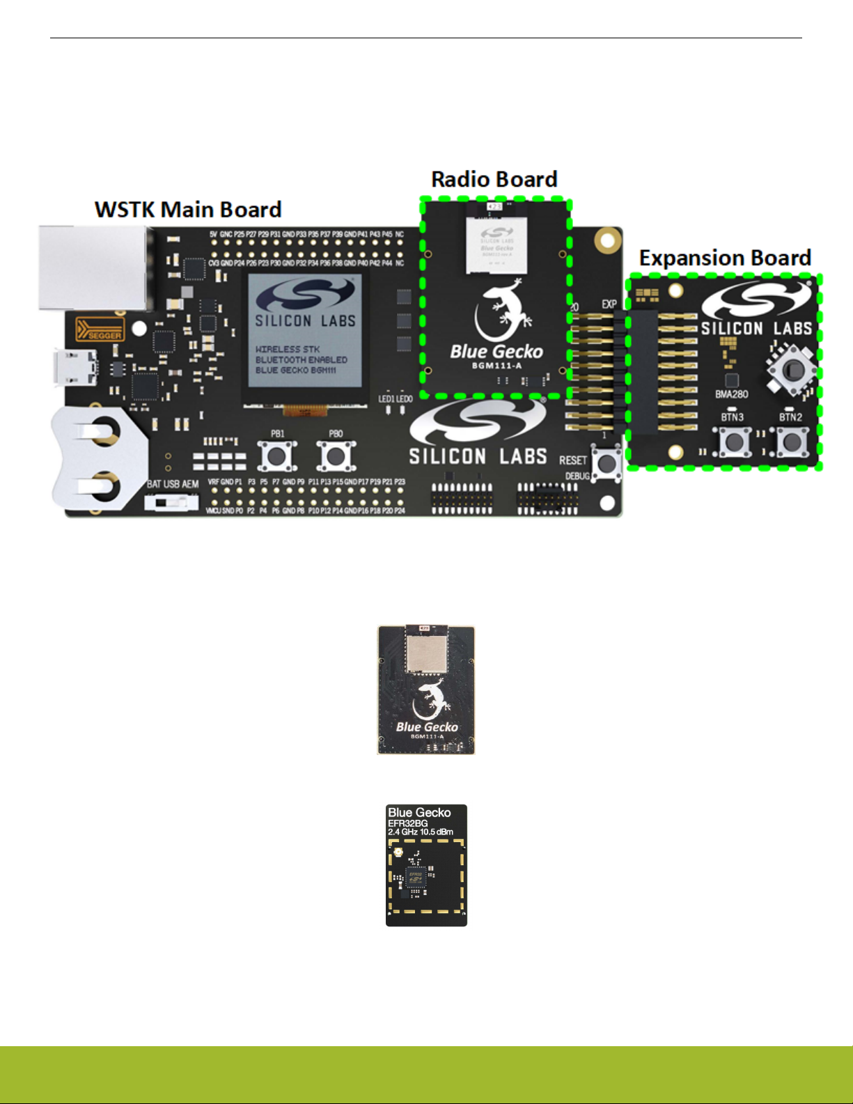
As seen in the figure below, the Wireless Gecko Wireless Starter Kit consists of three components:
• The Wireless Starter Kit (WSTK) main board
• The Radio Board
• The Expansion Board (included in WSTKs for modules only, not SoCs)
Setup
Figure 2.1. Wireless Gecko Wireless Starter Kit
The actual Wireless Gecko device is contained in the radio board. Therefore, the radio board will vary depending on the Wireless
Gecko device you want to work with (module or SoC). The figures below show the radio boards for a BGM111 module and then for an
EFR32BG1 SoC.
Figure 2.2. Module Radio Board
Figure 2.3. SoC Radio Board
For power measurements, only the WSTK and the radio board are necessary. See the applicable reference manual for details about
the WSTK.
silabs.com | Building a more connected world. Rev. 0.5 | 4
Page 5
AN969: Measuring Power Consumption on Wireless Gecko Devices
Setup
2.2 Building and Loading a Test Application
If you have not already done so, install Simplicity Studio and the relevant SDK. Each SDK includes several software examples to create
application projects. Follow the directions in the applicable SDK Quick Start Guide to install Simplicity Studio, and build and flash the
example project to the device.
2.3 Configuring the WSTK Main Board
The WSTK main board supports three options for delivering power to the radio board: (1) through USB, (2) from a coin-cell battery, and
(3) from an external power supply.
For cleaner power measurements, an external supply is the better choice because powering through USB enables other circuitry on the
WSTK main board that may, in some cases, lead to slightly higher or noisier current readings. When powering from a coin-cell battery,
the battery’s series resistance or its limited current-sourcing capability after aging may lead to current consumption profiles with a pronounced exponential rise or decay response that could mask the real power consumption of the device under test (DUT).
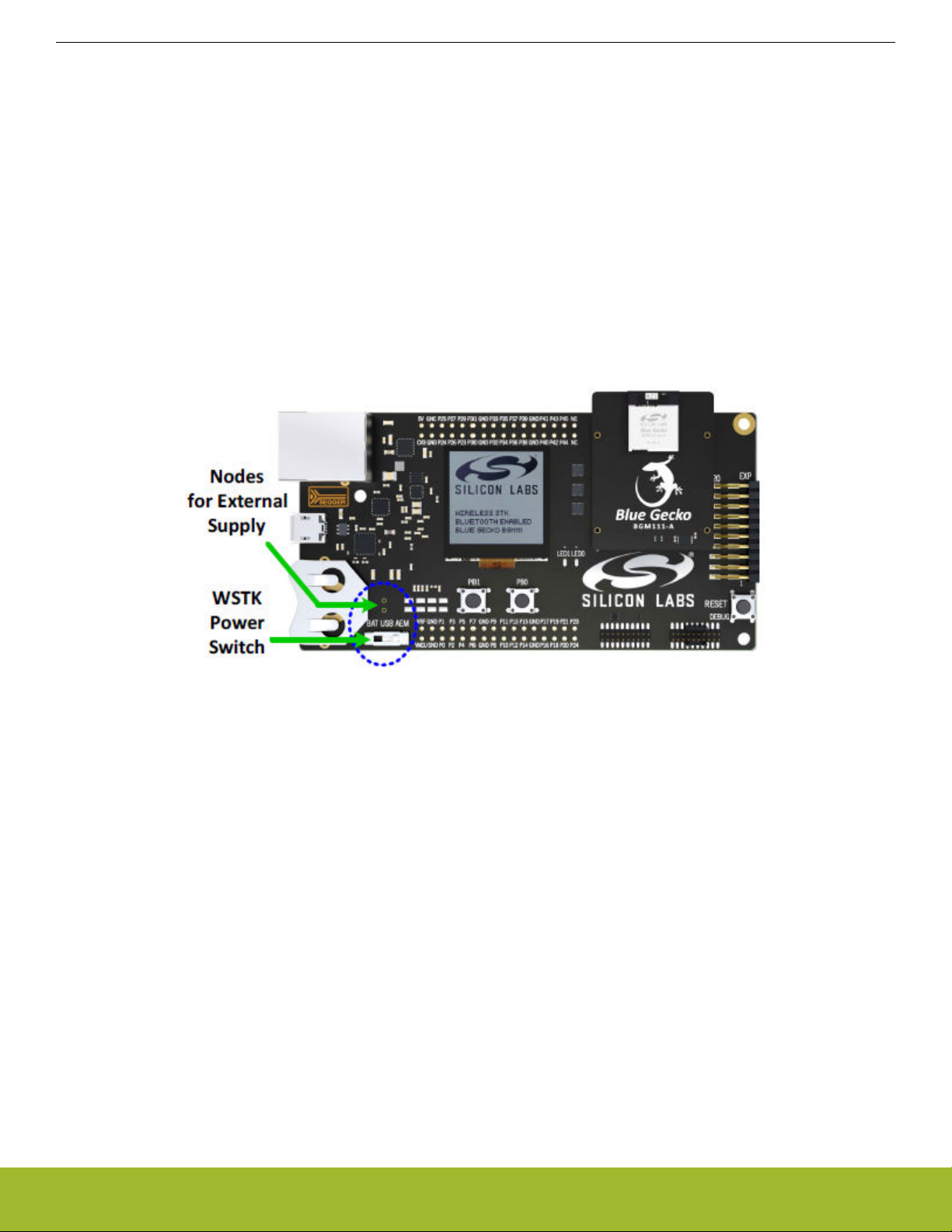
To power the Wireless Gecko device from an external source, change the power switch of the WSTK main board to BAT and apply 3.3
V (or your expected main supply voltage) at the nodes highlighted in the figure below (soldering a two-pin header there may be useful).
The silkscreen on the WSTK board shows the polarity of the nodes.
Figure 2.4. WSTK Main Board Powering Options
silabs.com | Building a more connected world. Rev. 0.5 | 5
Page 6

AN969: Measuring Power Consumption on Wireless Gecko Devices
Procedure
3. Procedure
Since the current profile of Wireless Gecko devices varies rapidly and dynamically over several orders of magnitude while switching
between different active and sleep modes, measuring the power consumption of these devices accurately is non-trivial.
This section introduces one of the best instruments available for observing the power consumption of Wireless Gecko devices: the Keysight N6705B DC power analyzer. Moreover, it will show you how to configure it both to power a Wireless Gecko device and to measure its current consumption.
For cases where a DC power analyzer is not accessible, see 4. Alternative Methods.
3.1 N6705B DC Power Analyzer Overview
The N6705B DC Power Analyzer integrates some of the capabilities offered by a power supply, a multi-meter, a scope, and a data
logger all in one box. While its chassis supports up to four DC power modules, only one is needed for basic measurements, such as
those discussed here. To learn more about the N6705B, consult the manufacturer’s website. The figure below shows its front panel.
Figure 3.1. N6705B DC Power Analyzer
silabs.com | Building a more connected world. Rev. 0.5 | 6
Page 7

AN969: Measuring Power Consumption on Wireless Gecko Devices
Procedure
3.2 Configuring the DC Power Analyzer
To configure the N6705B as an external supply to power a Wireless Gecko device, perform the following steps:
1. Power the instrument and turn it on.
2. Under “Select Output” in the front panel, choose the DC module to be used as source (default is “1”).
3. Under “Source” go to Settings, and enter the configuration in the following figure.
Note: Note that the following figure shows 4-wire sense, as is also shown in the figure in section 3.3 Running a Test. 4-wire sense
can be used in situations where high current is expected in order to maximize accuracy. Before enabling 4-wire sensing, connect
the +Sense and -Sense terminals to the same measurement points as the +Output and -Output terminal connections, as shown in
section 3.3 Running a Test. For most situations where high current is not expected, 2-wire sense can be used. Compare between
4-wire and 2-wire measurement set-ups to determine which configuration is appropriate for your use case.
4. Close the window.
Figure 3.2. DC Power Analyzer Source Settings
silabs.com | Building a more connected world. Rev. 0.5 | 7
Page 8

AN969: Measuring Power Consumption on Wireless Gecko Devices
Procedure
The primary advantage of the DC power analyzer is that it can measure the current drawn by the load connected to it, like a regular
multi-meter, by sampling it in time like a scope with very good resolution (up to 256k samples per capture). To configure the analyzer as
both a meter and a scope, perform the following steps:
1. Under “Select Output” in the front panel, choose the DC module you are using as source.
2. Go to “Properties”, and enter the configuration seen in the following figure as the meter properties.
Figure 3.3. DC Power Analyzer Meter Settings
3. Close the window.
4. Under “Select Output” in the front panel, choose the DC module being used as the source.
5. Under “Measure”, select "Scope View".
6. Go to “Properties”, and enter the configuration in the following figure as the Scope Properties.
Figure 3.4. DC Power Analyzer Scope Settings
7. Close the window.
silabs.com | Building a more connected world. Rev. 0.5 | 8
Page 9

AN969: Measuring Power Consumption on Wireless Gecko Devices
Procedure
3.3 Running a Test
At this point, your testbench should resemble the figure below. The radio board with the Wireless Gecko device running a test application should be mounted on the WSTK main board. The WSTK main board should be powered through its external supply nodes. The
power switch on the main board should be set to BAT. Finally, the DC analyzer should both supply 3.3 V (or your expected main supply
voltage) to the WSTK main board and measure its current consumption.
Note: The coin cell battery should be removed from the WSTK main board battery connector when using the BAT + and – pins from
external supply.
To start a test and view the current consumption of the DUT, perform the following steps:
1. Under “Select Output” in the N6705B front panel, choose the DC module you are using as source.
2. Under “Measure”, select Scope View.
3. Under “Power Supply Outputs” press the "On" button to enable the DC module you are using as source. At this point, the device
will reset, power up, and then start functioning.
4. Press the "Run/Stop" button on the N6705B front panel to start monitoring the current consumed by the device as it functions.
5. Use the knobs under “Waveform Display” to adjust the x and y axis scaling of the signal measured for a better view of the current
profiles captured.
Figure 3.5. Testbench for 4-Wire Sensing Power Consumption Measurements
silabs.com | Building a more connected world. Rev. 0.5 | 9
Page 10

AN969: Measuring Power Consumption on Wireless Gecko Devices
Procedure
The following figure shows the current profile captured for a Series 1 EFR32xG radio board running an SoC-iBeacon example application, as described in detail in AN1246: EFR32BG SoC Bluetooth® Smart Device Power Consumption Measurements. On the left, the
large periodic bursts correspond to the current consumed by the SoC while broadcasting a beacon every 100 ms. The flat parts between the bursts correspond to the current consumed while in sleep mode. The spikes observed while in sleep mode correspond to the
periodic dumping of charge on the load capacitor of the DC-DC converter to refresh its output voltage. See AN0948.1/AN0948.2: Power
Configurations and DC-DC for more details about DC-DC converter operation and power configurations for Series 1 and Series 2 devices, respectively.
On the right, a zoomed-in view of one of the large bursts shows in more detail the timing and magnitude of the TX and RX events taking
place while broadcasting the beacon (and listening for a response) over the three channel frequencies assigned for advertising in the
Bluetooth LE protocol.
Figure 3.6. EFR32BG Radio Board Current Consumption Profile Example
silabs.com | Building a more connected world. Rev. 0.5 | 10
Page 11

AN969: Measuring Power Consumption on Wireless Gecko Devices
Alternative Methods
4. Alternative Methods
Measuring the power consumption of Wireless Gecko devices with a DC Power Analyzer is ideal but not always feasible. For this reason, this section provides a brief overview of two alternative methods for making power measurements. For cost-constrained development environments, a combination of the two methods described in this section (Energy Profiler and Voltage Sampling with a scope)
can be a good alternative to a high-end instrument, such as the N6705B.
4.1 Energy Profiler
The Energy Profiler in Simplicity Studio is a software tool that works together with the Advanced Energy Monitoring (AEM) circuitry built
into the WSTK main board to allow measuring, plotting, and optimizing in real time the current and energy consumption of your test
device. To learn more about AEM, see the WSTK's Reference Manual. For more details on the Energy Profiler, refer to to UG343: Mul-
ti-Node Energy Profiler User’s Guide.
Assuming that the Wireless Gecko device is already programmed with the desired application, you can measure its power consumption
with the Energy Profiler by performing the following steps:
1. Connect the WSTK main board to your computer via USB.
2. Set the power switch on the WSTK main board to AEM.
3. Open Simplicity Studio.
4. Select the WSTK "J-Link Silicon Labs" in the Debug Adapters view.
5. Click the Tools icon ('wrench'), select Energy Profiler, and click [OK].
6. Click [Quick Access] under Current Device, and select Start Energy Capture.
7. Select the WSTK "J-Link Silicon Labs" and click [OK].
8. Play with the Y and X axis scaling and scrolling options to adjust the display or
9. Click the green "Running" button to stop capture (label changes to "Paused").
The following three figures show Energy Profiler screenshots of the curves and measurements obtained for a Series 2 EFR32xG22
SoC radio board running the SoC-iBeacon application mentioned in section 3.3 Running a Test. Specifically, the first figure shows plots
of the current profile captured (two beacon broadcast events) and the DUT’s average current on a logarithmic scale. The second figure
highlights the average current, average power and total energy consumption measured for the DUT while in sleep mode (cursors can
be enabled in the Energy Profiler by left-clicking and dragging on the plot), also on a logarithmic scale. Finally, the third figure shows a
zoomed-in view of one of the beacon broadcasts and its corresponding current, power, and energy measured in linear scale.
Figure 4.1. Current Profile and Supply Voltage for a Series 2 EFR32BG22 SoC Running the SoC-iBeacon Application
silabs.com | Building a more connected world. Rev. 0.5 | 11
Page 12

AN969: Measuring Power Consumption on Wireless Gecko Devices
Alternative Methods
Figure 4.2. Measured Current/Power/Energy in Sleep Mode
Figure 4.3. Measured Current/Power/Energy in Active Mode
Note: To display the plot of the measured supply, click the [Voltage] control on the top-right area of the Energy Profiler window. Also,
for a better view of low-magnitude current measurements, change the Y-axis scaling from linear to logarithmic by clicking the control
with a curve on the bottom-left area of the plot.
The Energy Profiler offers certain advantages over a DC power analyzer including lower cost, portability, and real-time energy debugging and optimization capabilities. However, its “scope” capabilities and measurement accuracy (1 μA) are limited by the 10 kHz maximum sampling rate of the AEM circuitry on the WSTK. Because of this, the resolution of the plots displayed is insufficient to see every
transition in the current profile of a test device in detail. This may be inconvenient in some cases but, most importantly, the overall average measurements provided by the Energy Profiler closely approximate those for a DC power analyzer.
silabs.com | Building a more connected world. Rev. 0.5 | 12
Page 13

AN969: Measuring Power Consumption on Wireless Gecko Devices
Alternative Methods
4.2 Voltage Sampling Across Resistor
Another method for measuring power consumption is illustrated in the diagram below. By placing a low-value resistor in series with the
supply node to the DUT and using an oscilloscope to sample the voltage difference across the resistor while the DUT is in operation,
the current and energy consumption of the DUT can be estimated.
Figure 4.4. Testbench Setup for Power Measuring Method
With a typical two channel scope, the current profile can be plotted as a math function defined by (CH2-CH1)/R while triggering with the
falling edge of CH2.
The main advantage of this approach is that measurements can be collected quickly with relatively easy-to-access lab instruments. Also, unlike the Energy Profiler, this approach allows you to observe every transition in the current profile of the test device easily since
the sampling resolution of most modern scopes is relatively high. Some important drawbacks, however, include that measurement accuracy for very low signal levels (for example, during sleep) can be poor due to the thermal noise added by the series resistor at the
supply node and to any offsets in your setup while taking a differential measurement.
silabs.com | Building a more connected world. Rev. 0.5 | 13
Page 14

AN969: Measuring Power Consumption on Wireless Gecko Devices
Document Revision History
5. Document Revision History
Revision 0.5
• Remove reference to AN713: Measuring EM35x Power Consumption for Sleepy End Devices using EmberZNet.
• Update Simplicity Studio instructions and references so they apply to both v4 and v5.
Revision 0.4
• Move Bluetooth i-Beacon testing on Series 1 EFR32BG devices to the new AN1246: EFR32BG SoC Bluetooth® Smart Device Power Consumption Measurements.
• Generalize the content in this document so that it applies to all EFR32xG devices.
silabs.com | Building a more connected world. Rev. 0.5 | 14
Page 15

Smart.
Connected.
Energy-Friendly.
Products
www.silabs.com/products
Disclaimer
Silicon Labs intends to provide customers with the latest, accurate, and in-depth documentation of all peripherals and modules available for system and software implementers using or
intending to use the Silicon Labs products. Characterization data, available modules and peripherals, memory sizes and memory addresses refer to each specific device, and "Typical"
parameters provided can and do vary in different applications. Application examples described herein are for illustrative purposes only . Silicon Labs reserves the right to make changes without
further notice to the product information, specifications, and descriptions herein, and does not give warranties as to the accuracy or completeness of the included information. Without prior
notification, Silicon Labs may update product firmware during the manufacturing process for security or reliability reasons. Such changes will not alter the specifications or the performance
of the product. Silicon Labs shall have no liability for the consequences of use of the information supplied in this document. This document does not imply or expressly grant any license
to design or fabricate any integrated circuits. The products are not designed or authorized to be used within any FDA Class III devices, applications for which FDA premarket approval is
required, or Life Support Systems without the specific written consent of Silicon Labs. A "Life Support System" is any product or system intended to support or sustain life and/or health,
which, if it fails, can be reasonably expected to result in significant personal injury or death. Silicon Labs products are not designed or authorized for military applications. Silicon Labs
products shall under no circumstances be used in weapons of mass destruction including (but not limited to) nuclear, biological or chemical weapons, or missiles capable of delivering
such weapons. Silicon Labs disclaims all express and implied warranties and shall not be responsible or liable for any injuries or damages related to use of a Silicon Labs product in such
unauthorized applications.
Trademark Information
Silicon Laboratories Inc.®, Silicon Laboratories®, Silicon Labs®, SiLabs® and the Silicon Labs logo®, Bluegiga®, Bluegiga Logo®, ClockBuilder®, CMEMS®, DSPLL®, EFM®, EFM32®,
EFR, Ember®, Energy Micro, Energy Micro logo and combinations thereof, "the world’s most energy friendly microcontrollers", Ember®, EZLink®, EZRadio®, EZRadioPRO®, Gecko®,
Gecko OS, Gecko OS Studio, ISOmodem®, Precision32®, ProSLIC®, Simplicity Studio®, SiPHY®, Telegesis, the Telegesis Logo®, USBXpress® , Zentri, the Zentri logo and Zentri DMS, ZWave®, and others are trademarks or registered trademarks of Silicon Labs. ARM, CORTEX, Cortex-M3 and THUMB are trademarks or registered trademarks of ARM Holdings. Keil is a
registered trademark of ARM Limited. Wi-Fi is a registered trademark of the Wi-Fi Alliance. All other products or brand names mentioned herein are trademarks of their respective holders.
Silicon Laboratories Inc.
400 West Cesar Chavez
Austin, TX 78701
USA
Quality
www.silabs.com/quality
Support and Community
community.silabs.com
http://www.silabs.com
 Loading...