

Page 1
Si824xClassD-KIT
CLASS D AUDIO AMPLIFIER REFERENCE DESIGN USER ’S GUIDE
1. Kit Contents
The Si824x Class D Audio Amplifier Reference Design Kit contains the following items:
Audio Class D Amplifier reference design board featuring:
Si8241 ISOdriver
Si8410 Digital Isolator
2. Introduction
This User's Guide discusses the Silicon Labs Audio Class D amplifier reference design, a stereo, two-state, halfbridge Class D amplifier leveraging the performance advantages of the Si8241 ISOdriver. This two-channel Class
D Audio Amplifier delivers 120 W per channel into 8 , while enabling < 0.02% THD at 60 W and > 95 dB SNR.
High-power audio systems are adopting digital audio technology and evolving toward lower-power, “green”
products that meet Energy Star™ guidelines. Class-D audio systems have started penetrating the high-end
markets where low noise, extremely good THD performance, and very high ou tput power are requir ed in consumer
and industrial applications. The Si824x audio driver family consists of single-chip, isolated, Class-D gate drivers
powering audio systems delivering from 30 W up to 1000 W of audio power.
Occasionally, a new IC is introduced that challenges the current technological hegemony. With features that make
these products the perfect drivers for Class D amplification, the Silicon Labs Si8241/44 Audio Gate Drivers
represent a new standard for the Class D amplifier industry. Based on Silicon Labs' proprietary isolation
technology, the Si824x audio drivers incorporate input-to-output isolation that enables level-translation of signals
without additional external circuits. The Si824x audio drivers feature adjustable dead-time control for achieving
optimal THD, overlap protection that safeguards against shoot-through current damage, robust immunity to latchup and high-voltage transients, and lower BOM costs and PCB footprints compared to non-isolated gate drive
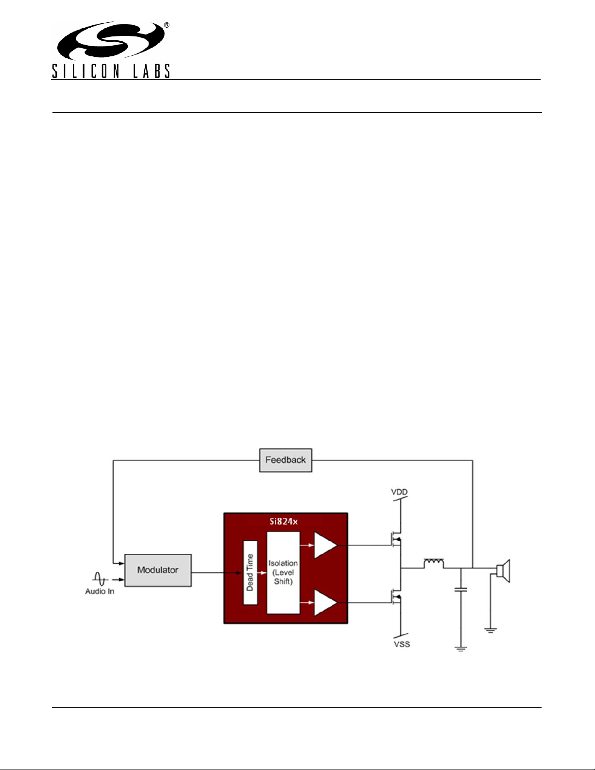
solutions. A typical audio driver application using the Si824x is shown in Figure 1. For more information on the
Si824x audio driver, refer to the Si824x datasheet at www.silabs.com/audio.
Figure 1. Si824x-Based Class D Audio Driver Block Diagram
Rev. 0.2 11/10 Copyright © 2010 by Silicon Laboratories Si824xClassD-KIT
Page 2
Si824xClassD-KIT
3. Hardware Overview and Demo
3.1. Reference Design Board Architecture
The Silicon Labs Class D reference design architecture uses a phase-shift, self-oscillating modulation approach
that is capable of achieving far greater signal-to-noise ratio than clock driven amplifiers (see Figure 2). This selfoscillating implementation eliminates the circuitry necessary to generate the triangle waveform. To keep the circuit
as simple as possible, a two-state, half-bridge is implemented and exemplifies the benefits of using the Si8241
Audio Gate Driver.
Figure 2. Block Diagram of Si8241-Based Class D Amplifier
3.2. Setting up the Class D Amplifier
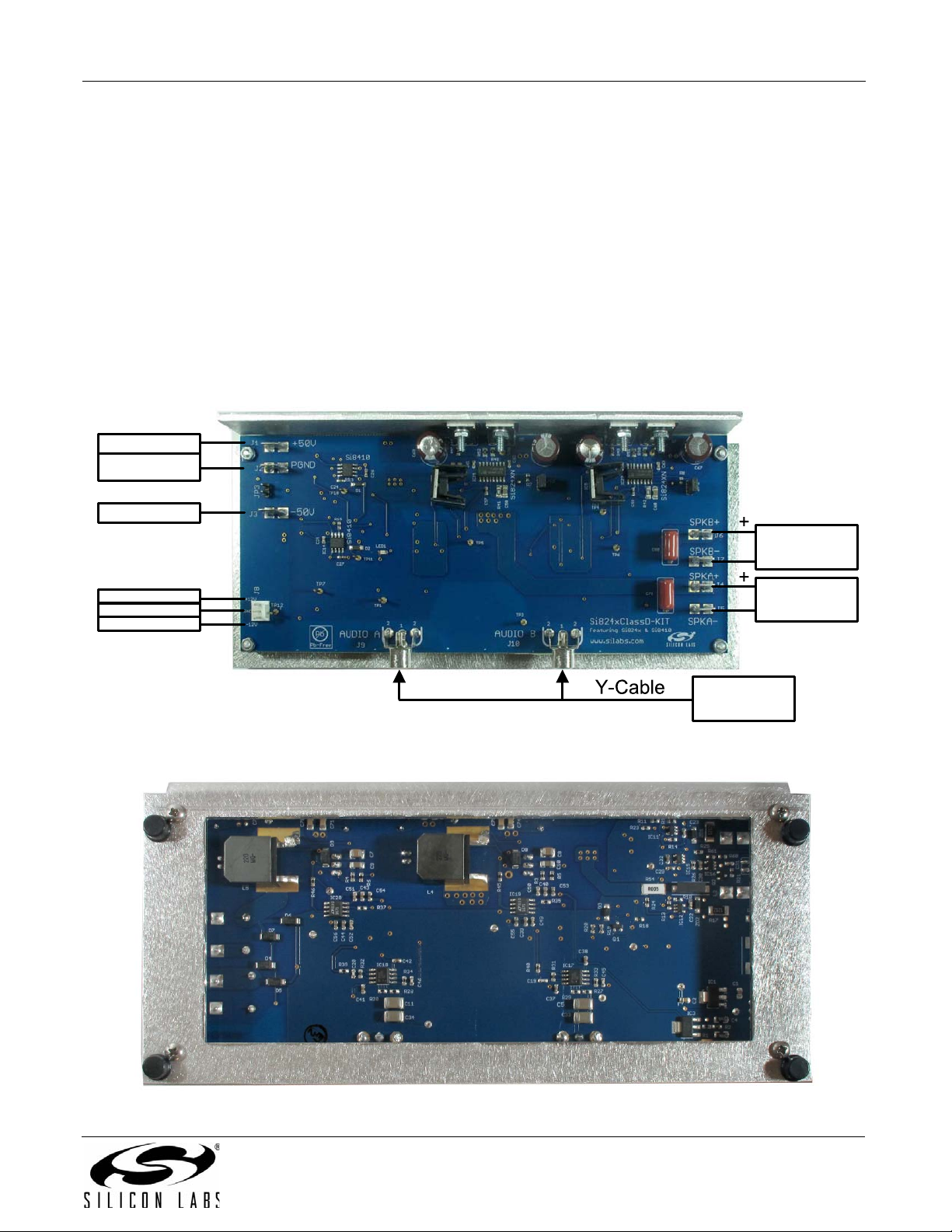
Figure 3 illustrates connections necessary to power the Class D amplifier. The user will need the following items:
MP3 player (or equivalent line out audio source)
Audio Y-Cable (stereo male to Dual RCA Male)
±50 V supply capable of sourcing 3 Amps
±12 V supply capable of sourcing 500 mA
Two speakers (up to 150 W)
Silicon Labs Class D reference design board
Warning:
1. To protect the amplifier and speakers, before turning on the main power (the ±50 V supplies) to the amplifier, ensure that
the audio source from the MP3 player has its volume set to the lowest possible level.
2. The L-bracket can heat up to 80 °C and should be handled with care.
2 Rev. 0.2
Page 3
Si824xClassD-KIT
Speaker B
(up to 150 W)
_
_
Speaker A
(up to 150 W)
Audio Source/
MP3 Player
+12 V (500 mA)
-12 V (500 mA)
+50 V (3 A)
-50 V (3 A)
PGND
GND
3.3. Powering up the Class D Amplifier and Playing Music
After the audio source, audio Y-cable, supplies, and speakers have been properly connected as shown in Figure 3.
1. Turn on the ±12 V supplies.
2. Then, turn on the ±50 V supplies. Notice that LED1 should turn on for abou t 1 sec and then turn of f. This on and
off sequence clears any overcurrent protection faults and indicates to the user that the amplifier is ready to
amplify the audio input signal. If the LED does not turn off after about 1 sec, cycle on and off the ±12 V supplies.
Repeat this step until the LED turns off. If the LED never turns off, the board has probably been damaged.
3. With the audio source's volume turned down to its lowest output level, start the audio source.
4. Adjust the volume to the desired listening level.
5. Enjoy your music!
Note: If the power being delivered to the speakers is too great, the overcurrent protection circuitry will trip and shut
off audio to the speakers, protecting the amplifier. LED1 will turn on in this condition. See "4.4. Overcurrent
Protection" on page 4 for more details on clearing this fault condition.
Figure 3. Si824xClassD-KIT (Top V iew)
Figure 4. Si824xClassD-KIT (Bottom View)
Rev. 0.2 3
Page 4
Si824xClassD-KIT
Si8241
ISOdriver
-38V
PWM
NC
VDDI
GNDI
DISABLE
DT
NC
VDDI
VDDA
VOA
GNDA
NC
NC
VDDB
VOB
GNDB
-50V
+50V
C1
C3
PWM
+5V
C2
SHDN_HI
R3
C4
D1
R1
R2
-38V
4. Additional Features and Architectural Considerations
4.1. Gate Drive Structure
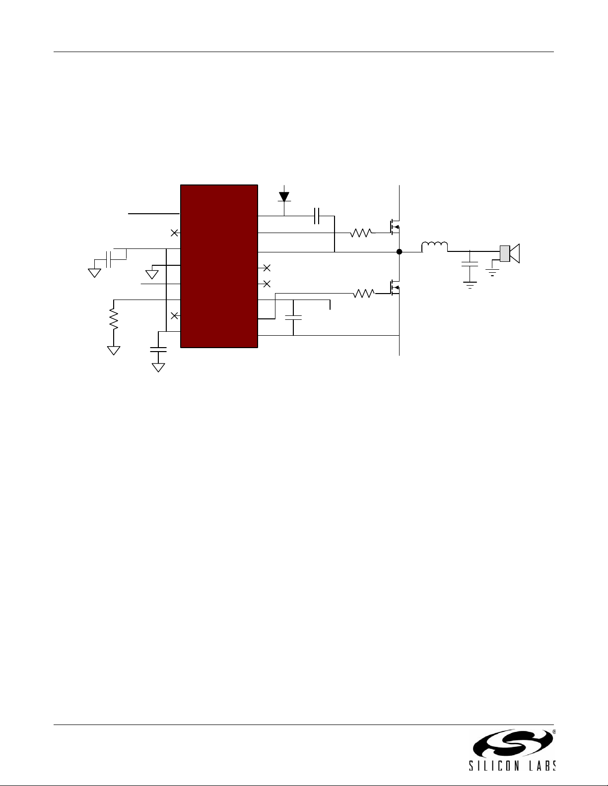
Figure 5 illustrates the ease with which the Si8241 can drive a two-state, half-bridge class D amplifier. The boot
supply tied to D1 must be 12 V higher than the –50 V reference (–38 V) so that the MOSFETs each have a 12 V
drive signal. The closed loop gain of the Silicon Labs Class D reference design is implemented such that
approximately 1 Vpp input will yield full output power into an 8 load.
Figure 5. Si8241 Audio Gate Driver Gate Drive Circuit
4.2. Self Oscillation
The amplifier is self-oscillating, enabling its signal-to-noise ratio to far exceed that of a clock driven system. The
main mechanism for this is the delta-sigma effect of shifting in-band noise to a much higher out-of-band frequency.
The amplifier is a basic, phase-shift type, which has significant advantages over an amplifier running as a
hysteretic oscillator. There is a pole in the forward path G(s) and a pole in the feedback path H(s). The 180 ° phase
shift, coupled with the transport delay, yields an oscillation frequency of nearly 500 kHz. The frequency of
oscillation is set by capacitors in each audio channel where reducing capacitance value increases oscillation
frequency. Tight tolerance capacitors are used to keep the channel frequencies as close to each other as possible.
4.3. Heat Sink L-Bracket
The amplifier design includes an L-bracket to sink excess heat from the power transistors. At full power, the Lbracket's temperature should increase to no higher than 80 degrees Celsius.
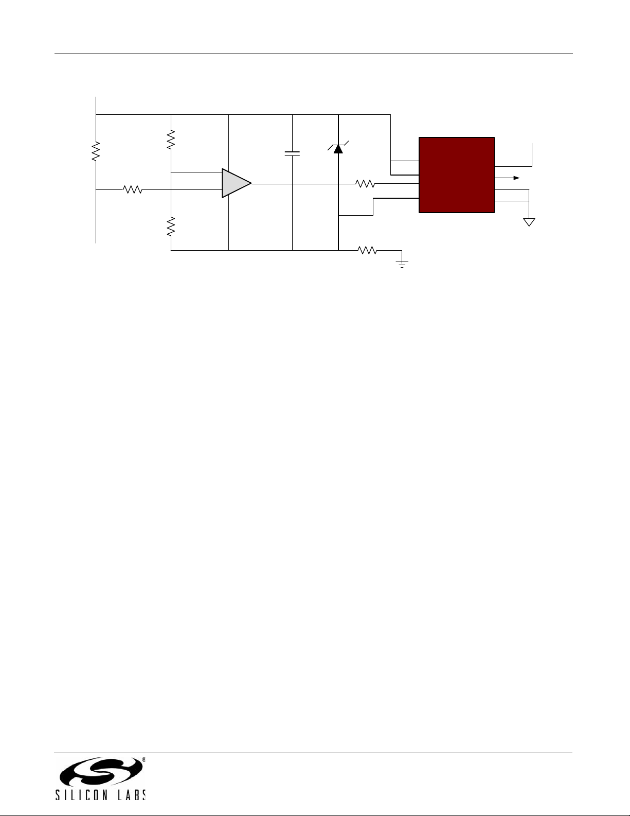
4.4. Overcurrent Protection
The Silicon Labs Class D reference design has an overcurrent protection circuit consisting of a low-power
comparator floating off the upper and lower bus voltages. The upper rail circuit is shown in Figure 6 and is
duplicated on the lower rail. It monitors the current flowing through the 0.005 resistor (RSENSE). Zener diode D1
and resistor R4 supply power to the comparator and the Silicon Labs Si8410 digital isolator. The Si8410 performs
the necessary level shifting to interface to the shutdown circuitry. Th e circuit is set to trip at roughly a 20 A fau lt,
usually caused by a short-circuit acro ss the spe aker term inals or a lar ge over drive sign al at the a udio inpu ts. Note
the upper and lower overcurrent circuits are ORed together through a pair of diodes and sent to the reset control
circuit. The normally low Si8410 A1 input is driven high upon detection of an overcurrent cond ition a nd ass erts the
SHUTDOWN signal, forcing the reset controller to assert a reset signal, momentarily halting amplifier operation.
The reset control circuit attempts restart after one second, and, if the fault is still present, again cycles reset in
“hiccup” mode with a frequency of one second. This process continues until the fault is removed. Overcurrent
protection can be removed by uninstalling JP1 and JP2.
4 Rev. 0.2
Page 5
Si824xClassD-KIT
+
-
C1
R2
R4
R3
Si8410
Digital Isolator
R5
R1
RSENSE
GND2
GND2
GND1
A1
VDD1
VDD1
To High Side
MOSFET
VDD2
B1
5V
SHUTDOWN
D1
50V
Figure 6. Over Current Protection Circuit
4.5. Undervoltage Protection
The undervoltage protection comparator monitors the positive bus voltage and releases the undervoltage lockout
when the voltage is above 37 V . The amplifier starts up after a one-second delay. Note that the red LED remains lit
when the amplifier is in shutdown mode and turns off when the amplifier is enabled.
4.6. Other Features
A protection circuit jumper (JP 3) option is included that allows the amplifier to be manually shut down. This jumper
can be replaced with a switch or other control circuit, allowing the amplifier to be muted. The one-second
undervoltage lockout delay allows the op-amps and comparator to settle before the shut-down circuit is released,
thereby preventing speaker p ops. To aid in system performance evaluation, there are individual jumper options
(JP1 and JP2) on each channel that allow the user to enable or disable each channel independently of the other.
4.7. Performance
The Silicon Labs Class D reference design board was tested for THD + N, SNR, DFD, and IFD with an Audio
Precision analyzer. During these tests, the main power (the ±50 V supplies) used a TR 180 fr om Hy pex e lec troni cs
(a low-noise supply) to maximize the amplifier's measured performance. Refer to “AN542: Performance
Improvements in Class D Audio Amplifiers using Si824x Audio Drivers” for additional information concerning the
amplifier's noise and efficiency performance and a more in-depth discussion concerning the amplifier's
architectural design. Please visit www.silabs.com/audio.
Rev. 0.2 5
Page 6

Si824xClassD-KIT
5. Si8241-Based Class D Amplifier Connection Description
The Si8241-based Class D Amplifier has two Si8241 ISOdrivers and two Si8410 digital isolators installed. Refer to
Figure 7 for the locations of the var ious I/O connectors and major components. Relevant user connection points
are detailed below.
J1 +50 V Positive Input Power: Input power connection +50 V, 3 A.
J2 PGND Power Ground Return, 0 V.
J3 –50 V Negative Input Power: Input power connection –50 V, 3 A.
J4 SPKA+ Speaker A positive terminal
J5 SPKA– Speaker A negative terminal
J6 SPKB+ Speaker B positive terminal
J7 SPKB– Speaker B negative terminal
J8 VBIAS ±12 V Bias supply connector (500 mA)
J9 AUDIO A RCA input female connector channel A
J10 AUDTIO B RCA input female connector channel B
JP1 OCPDISA Over current protection disable channel A channel
JP2 OCPDISB Over current protection disable channel B channel
JP3 MUTE Amplifier Mute or manual shut down
LED1 FAULT Over current protection fault indicator LED
Figure 7. Si8241 Si8241-Based Class D Amplifier Silkscreen
5.1. Voltage and Current Sense Test Points
The Si824x Class D Audio Amplifier reference design has several test points. These test points correspond to the
respective pins on the Si8241, S i8410 as well as other useful inspection points. See “6. Schem atics” for more
details.
6 Rev. 0.2
Page 7

6. Schematics
Si824xClassD-KIT
Figure 8. Si824x Class D Audio Amplifier Reference Design Schematic (1 of 2)
Rev. 0.2 7
Page 8

Si824xClassD-KIT
8 Rev. 0.2
Figure 9. Si824x Class D Audio Amplifier Reference Design Schematic (2 of 2)
Page 9

Si824xClassD-KIT
7. Bill of Materials
Table 1. Si824x Class D Audio Amplifier Reference Design Bill of Materials
Qty Ref Description Mfr. Part Number Mfr Digikey Part Number
1µF, 25V, X5R,
2C1, C2
0805 Ceramic
Capacitor
08053D105KAT2A AVX 478-1409-6-ND
2C3, C4
C24–C27,
14
C29, C30,
C37–C44
1C6
2C7,C8
4
2C57, C59
7
C9, C10,
C58, C60
C22, C23,
C31,
C49–C52
1 µF, 16 V, 3216
Tantalum Capacitor
0.1 µF, 50 V, X7R,
0603 Ceramic
Capacitor
10 µF, 10 V, 3216
Tantalum Capacitor
1µF, 100V, X7R,
1210 Ceramic
Capacitor
1µF, 25V, X5R,
1206 Ceramic
Capacitor
1µF, 10V, X5R,
0603 Ceramic
Capacitor
0.01 µF, 50 V, X7R,
0603 Ceramic
Capacitor
T491A105M016AT Kemet 399-3681-6-ND
GRM188R71H104
KA93D
T491A106M010AT Kemet 399-3686-6-ND
GRM32ER72A105
KA01L
GRM319R61E105K
C36D
GRM188R61A105K
A61D
06035C103KAT2A AVX 478-1227-6-ND
Murata 490-1519-6-ND
Murata 490-1857-1-ND
Murata 490-1807-6-ND
Murata 490-1543-6-ND
1C32
4
4
4 C53–C56
4 C61–C64
C5, C11,
C33, C34
C19, C20,
C45, C46
10 pF, 50 V, COG ,
0603 Ceramic
Capacitor
100 µF, 6.3 V, X5R,
1812 Ceramic
Capacitor
100 pF, 50 V, COG,
0603 Ceramic
Capacitor
4.7µF, 6.3V, X5R,
0603 Ceramic
Capacitor
0.47 µF, 16 V, X5R,
0603 Ceramic
Capacitor
06035A100JAT2A AVX 478-1163-6-ND
C4532X5R0J107M TDK 445-1413-2-ND
GRM1885C1H101J
A01D
06036D475MAT2A AVX 478-2582-6-ND
C0603X7R160-
474MNE
Rev. 0.2 9
Murata 490-1427-6-ND
AVX 478-1248-6-ND
Page 10

Si824xClassD-KIT
Table 1. Si824x Class D Audio Amplifier Reference Design Bill of Materials (Continued)
Qty Ref Description Mfr. Part Number Mfr Digikey Part Number
4 C67–C70
4 C71–C74
4 C75–C78
2C79, C80
3D1–D3
6D4–D9
2ZD1, ZD2
COG , 1206 Ceramic
82 µF, 63 V, KZE
Series Electrolytic
Cap
0.1 µF, 100 V, X7R,
1206 Ceramic
Capacitor
0.01 µF, 100 V,
Capacitor
0.47 µF, 250 V Film
Capacitor
100 V 150 mA
SOD123 Diode
Fast Recovery
200 V 2 A Diode
SMA
Diode Zener
500 mW 5.1 V
SOD-123
EKZE630ESS820M
JC5S
12061C104MAT2A AVX 478-3786-6-ND
12061C103JAT2A AVX 478-3783-6-ND
ECQ-E2474KB Panasonic ECG P10975-ND
1N4148W-13-F Diodes Inc. 1N4148W-13-FDIDKR-ND
MURA120T3G On Semi MURA120T3GOSCT-ND
MMSZ4689-TP
Chemi-Con 565-1721-ND
Micro
Commercial Co.
MMSZ4689-TPMSCT-ND
1IC1
1IC3
2IC4, IC5
IC11, IC12,
3
2 IC13, IC14
1IC15
2 IC17, IC18
IC16
IC Volt age Reg 5.0 V
tive Regulators SOT-
High-Voltage Adjust-
200 mA SOT223
Adjustable Nega-
223
able Regulator
TO220
CMOS Comparator
SOT23-5
Single Channel
Digital Isolator
SOIC8
Voltage Supervisor
with Adjustable
Power-on Reset
SOT23-5
IC Opamp Audio
Ster AB 8SOIC
ZSR500GTA ZETEX ZSR500GCT-ND
LM337IMP National Semi LM337IMPDKR-ND
TL783CKCSE3 TI 296-20687-5-ND
LMC7211BIM5/
NOPB
Si8410BB-D-IS Silabs
ISL88011IH531Z-
TK
LM4562MA/NOPB National Semi LM4562MA-ND
National Semi LMC7211BIM5CT-ND
Intersil ISL88011IH531Z-TKDKR-ND
10 Rev. 0.2
Page 11

Si824xClassD-KIT
Table 1. Si824x Class D Audio Amplifier Reference Design Bill of Materials (Continued)
Qty Ref Description Mfr. Part Number Mfr Digikey Part Number
2 IC19, IC20
2 IC21, IC22
7 J1–J7 1/4 inch-Faston 62409-1
1 J8 3 Pin Conn Header 22-23-2031 Molex Inc. WM4201-ND
2 J9, J10
3 JP1–JP3 Jumper TSW-102-07-T-S Samtec SAM1035-02-ND
3 L1, L2, L35 Ferrite Bead 2773021447 Fair-Rite
2L4, L5
1LED1
2Q1, Q2
IC Comp Grnd-sens-
ing LowPwr 8SOIC
Isodriver Narrow
Body
Conn RCA Jack
Metal R/A YEL PCB
22µH, 7A, 8.3m
Inductor
LED Chip LED
645NM Red Diff
0805
MOSFET N-CH 60 V
280 mA
SOT-23
LT1671CS8#PBF Linear Tech LT1671CS8#PBF-ND
Si8241BB-B-IS1 Silabs
Tyco
Electronics
RCJ-014 CUI Inc. CP-1403-ND
7G14A-220M-R Sagami
LH R974-LP-1-0-
20-R18
NDS7002A Fairchild Semi NDS7002ACT-ND
Osram 475-1415-6-ND
A24742-ND
4Q4–Q7
1R1
2R2, R20
2R3, R4
2R5, R6
4
1R26
6
R7, R8,
R12, R13
R10, R11,
R14, R15,
R35, R37
1k, 0603 1% SMT
200V, 18A N-Ch a n-
nel MOSFET
249 , 0603 1%
SMT Resistor
750 , 0603 1%
SMT Resistor
82.5 , 0603 1%
SMT Resistor
698 , 0603 1%
SMT Resistor
49.9 k, 0603 1%
SMT Resistor
12 k, 0603 1%
SMT Resistor
Resistor
FDP18N20F Fairchild Semi FDP18N20F-ND
ERJ-3EKF2490V Panasonic ECG P249HDKR-ND
ERJ-3EKF7500V Panasonic ECG P750HCT-ND
ERJ-3EKF82R5V Panasonic ECG P82.5HDKR-ND
ERJ-3EKF6980V Panasonic ECG P698HDKR-ND
ERJ-3EKF4992V Panasonic ECG P49.9KHCT-ND
ERJ-3EKF1202V Panasonic ECG P12.0KHCT-ND
ERJ-3EKF1001V Panasonic ECG P1.00KHCT-ND
Rev. 0.2 11
Page 12

Si824xClassD-KIT
Table 1. Si824x Class D Audio Amplifier Reference Design Bill of Materials (Continued)
Qty Ref Description Mfr. Part Number Mfr Digikey Part Number
2R16, R17
R18, R21,
3
2R29, R30
4
1R25
2R27, R28
2R31, R32
2R33, R34
3
R60
R23, R24,
R39, R40
R19, R41,
R42
2k, 0603 1% SMT
12.1 k, 2010 1%
SMT Resistor
20 k, 0603 1%
SMT Resistor
4.99 k, 0603 1%
SMT Resistor
100 k, 0603 1%
SMT Resistor
121 k, 0603 1%
SMT Resistor
1.3 k, 0603 1%
SMT Resistor
7.5 k, 0603 1%
SMT Resistor
300 k, 0603 1%
SMT Resistor
Resistor
ERJ-12SF1212U Panasonic ECG P12.1KACCT-ND
ERJ-3EKF2002V Panasonic ECG P20.0KHCT-ND
ERJ-3EKF4991V Panasonic ECG P4.99KHCT-ND
ERJ-3EKF1003V Panasonic ECG P100KHCT-ND
ERJ-3EKF1213V Panasonic ECG P121KHCT-ND
ERJ-3EKF1301V Panasonic ECG P1.30KHCT-ND
ERJ-3EKF7501V Panasonic ECG P7.50KHCT-ND
ERJ-3EKF3003V Panasonic ECG P300KHCT-ND
ERJ-3EKF2001V Panasonic ECG P2.00KHCT-ND
2R45, R46
4 R47–R50
2R51, R52
2R53, R54
1R55
1R61
2HS1
12 TP1-TP12 Test Pad
4
Shoulder
Washer
511 , 0603 1%
SMT Resistor
12.1 , 0805 1%
SMT Resistor
1 , 0805 1% SMT
Resistor
0.005 , 3264 1%
SMT Resistor
0 , 1206 1% SMT
Resistor
39.2 k 0603 1%
SMT Resistor
Heatsink TO-220
5W BLK
Washer/bushing #4
X .031"L NYLON
ERJ-3EKF5110V Panasonic ECG P511HCT-ND
ERJ-6ENF12R1V Panasonic ECG P12.1CCT-ND
RC0805FR-071RL Yageo 311-1.00CRCT-ND
MCS3264R005FE Panasonic ECG MCS3264R005FERCT-ND
ERJ-8GEY0R00V Panasonic ECG P0.0ECT-ND
ERJ-3EKF3922V Panasonic ECG P39.2KHCT-ND
76802B00000G
5
3103-2-00-21-00-
00-08-0
3049 Keystone 3049-ND
AAVID
Thermalloy
MILL-MAX
MAN.
HS121-ND
ED5052-ND
12 Rev. 0.2
Page 13

Si824xClassD-KIT
Table 1. Si824x Class D Audio Amplifier Reference Design Bill of Materials (Continued)
Qty Ref Description Mfr. Part Number Mfr Digikey Part Number
Insulator Mica
4 Insulator
4Screw
4Screw
.860X.520" .141"
TO-220
Hdwr Mtg Screw TO-
220CASE 4/40 THR
1PC
Hdwr Mtg Screw 1/
4" 4/40 , PCB L-
Bracket Mount
4672 Keystone 4672K-ND
4690 Keystone 4690K-ND
9900 Keystone 9900K-ND
4
4Nut
4 Standoff
1 HTSNK L Bracket Heat Sink SIHS-1
4
7J1-J7
2
Lock
Washer
Heat
Compound
Bumpons,
Feet, Pads,
Grips
JP1, JP2
Shorting
Jumper
Hdwr Mtg Lock-
washer Plastic 2PC
Hdwr Mtg Nut 4/40
Thread 2PC
Heat Trans
Compound Silicone
Stdoff Hex M/F 4-40
.375"L Alum
Bumpon Cylindrical
.312X.215 BLK
Conn Fast Recept
18-22 AWG .250
Conn Jumper
Shorting Gold Flash
4693 Keystone 4693K-ND
4694 Keystone 4694K-ND
860-150G MG Chemicals 473-1097-ND
8400 Keystone 8400K-ND
SJ61A6 3M SJ5744-0-ND
2-520264-2
SPC02SYAN
Red River PRC
MFG
Tyco
Electronics
Sullins
Connector
Solutions
A27821-ND
S9001-ND
Rev. 0.2 13
Page 14

Si824xClassD-KIT
8. Ordering Guide
Ordering Part Number Type
Si824xClassD-KIT
Audio Class D Amplifier reference design kit using
Si8241BB-B-IS1.
14 Rev. 0.2
Page 15

DOCUMENT CHANGE LIST
Revision 0.1 to Revision 0.2
Updated Table 1, “Si824x Class D Audio Amplifier
Reference Design Bill of Materials,” on page 9.
Si824xClassD-KIT
Rev. 0.2 15
Page 16

Si824xClassD-KIT
The information in this document is believed to be accurate in all respects at the time of publication but is subject to change without notice.
Silicon Laboratories assumes no responsibility for errors and omissions, and disclaims responsibility for any consequences resulting from
the use of information included herein. Additionally, Silicon Laboratories assumes no responsibility for the functioning of undescribed features
or parameters. Silicon Laboratories reserves the right to make changes without further notice. Silicon Laboratories makes no warranty, representation or guarantee regarding the suitability of its products for any particular purpose, nor does Silicon Laboratories assume any liability
arising out of the application or use of any product or circuit, and specifically disclaims any and all liability, including without limitation consequential or incidental damages. Silicon Laboratories products are not designed, intended, or authorized for use in applications intended to
support or sustain life, or for any other application in which the failure of the Silicon Laboratories product could create a situation where personal injury or death may occur. Should Buyer purchase or use Silicon Laboratories products for any such unintended or unauthorized application, Buyer shall indemnify and hold Silicon Laboratories harmless against all claims and damages.
The sale of this product contains no licenses to Power-One’s intellectual property. Contact Power-One, Inc. for appropriate licenses.
CONTACT INFORMATION
Silicon Laboratories Inc.
400 West Cesar Chavez
Austin, TX 78701
Tel: 1+(512) 416-8500
Fax: 1+(512) 416-9669
Toll Free: 1+(877) 444-3032
Please visit the Silicon Labs Technical Support web page:
https://www.silabs.com/support/pages/contacttechnicalsupport.aspx
and register to submit a technical support request.
Silicon Laboratories and Silicon Labs are trademarks of Silicon Laboratories Inc.
Other products or brandnames mentioned herein are trademarks or registered trademarks of their respective holders.
16 Rev. 0.2
 Loading...