

Page 1

AN332
Si47XX PROGRAMMING GUIDE
1. Introduction
This document provides an overview of the programming requirements for the Si4704/05/06/07/1x/2x/3x/4x/84/85
FM transmitter/AM/FM/SW/LW/WB receiver. The hardware control interface and software commands are detailed
along with several examples of the required steps to configure the device for various modes of operation.
2. Overview
This family of products is programmed using commands and responses. To perform an action, the system
controller writes a command byte and associated arguments, causing the device to execute the given command.
The device will, in turn, provide a response depending on the type of command that was sent. Section "4.
Commands and Responses" on page 6 and section "5. Commands and Properties" on page 7 describe the
procedures for using commands and responses and provide complete lists of commands, properties, and
responses.
The device has a slave control interface that allows the system controller to send commands to and receive
responses from the device using one of three serial protocols (or bus modes): 2-wire mode (I
compatible), 3-wire mode, or SPI mode.
2
C and SMBUS
Section "6. Control Interface" on page 224 describes the control interface in detail.
Section "7. Powerup" on page 232 describes options for the sequencing of VDD and VIO power supplies, selection
of the desired bus mode, provision of the reference clock, RCLK, and sending of the POWER_UP command.
Section "8. Powerdown" on page 239 describes sending the POWER_DOWN command and removing VDD and
VIO power supplies as necessary.
Section "9. Digital Audio Interface" on page 240 describes the digital audio format supported and how to operate
the device in digital mode.
Section "10. Timing" on page 243 describes the CTS (Clear to Send) timing indicating when the command has
been accepted and in most cases completed execution, and the STC (Seek/Tune Complete) timing indicating
when the Seek/Tune commands have completed execution.
Section "11. FM Transmitter" on page 249 describes the audio dynamic range control, limiter, pre-emphasis,
recommendations for maximizing audio volume for the FM transmitter.
Section "12. Programming Examples" on page 253 provides flowcharts and step-by-step procedures for
programming the device.
Rev. 0.8 12/11 Copyright © 2011 by Silicon Laboratories AN332
Page 2

AN332
Table 1. Product Family Function
Part
Number
General Description
Si4700 FM Receiver
Si4701 FM Receiver with RDS
Si4702 FM Receiver
Si4703 FM Receiver with RDS
Si4704 FM Receiver
Si4705 FM Receiver with RDS
Si4706
Si4707
1
High Performance RDS Receiver
1
WB Receiver with SAME
Si4708 FM Receiver
Si4709 FM Receiver with RDS
Si4710 FM Transmitter
Si4711 FM Transmitter with RDS
Si4712 FM Transmitter with RPS
Si4713 FM Transmitter with RDS & RPS
Si4720 FM Transceiver
Si4721 FM Transceiver with RDS
Si4730 AM/FM Receiver
High Performance RDS
2
RPS
SAME
Digital Input
Digital Output
Embedded FM antenna
Package Size (mm)
AEC-Q100 Qualified
4x4
4x4
3x3
3x3
3x3
3x3
3x3
3x3
2.5x2.5
2.5x2.5
3x3
3x3
3x3
3x3
3x3
3x3
3x3
RDS
FM Receiver
FM Transmitter
AM Receiver
WB Receiver
SW/LW Receiver
Si4731 AM/FM Receiver with RDS
Si4734 AM/SW/LW/FM Receiver
Si4735 AM/SW/LW/FM Receiver with RDS
Si4736 AM/FM/WB Receiver
Si4737 AM/FM/WB Receiver with RDS
Si4738 FM/WB Receiver
Si4739 FM/WB Receiver with RDS
Si4740
Notes:
2 Rev. 0.8
1
AM/FM Receiver
1. Si4706, Si4707, and Si474x are covered under NDA.
2. High Performance RDS is available in Si4705/31/35/85-D50 and later.
2
3x3
3x3
2
3x3
3x3
3x3
3x3
3x3
4x4
Page 3

Table 1. Product Family Function (Continued)
AN332
Si47411AM/FM Receiver with RDS
Si4742
Si4743
Si4744
Si4745
Si4749
1
AM/LW/SW/FM/WB Receiver
AM/LW/SW/FM/WB Receiver with
1
RDS
1
AM/LW/SW/FM Receiver
1
AM/LW/SW/FM Receiver with RDS
1
High-Performance RDS Receiver
Si4784 FM Receiver
Si4785 FM Receiver with RDS
Notes:
1. Si4706, Si4707, and Si474x are covered under NDA.
2. High Performance RDS is available in Si4705/31/35/85-D50 and later.
2
4x4
4x4
4x4
4x4
4x4
4x4
3x3
3x3
Rev. 0.8 3
Page 4

AN332
TABLE OF CONTENTS
Section Page
1. Introduction . . . . . . . . . . . . . . . . . . . . . . . . . . . . . . . . . . . . . . . . . . . . . . . . . . . . . . . . . . . . .1
2. Overview . . . . . . . . . . . . . . . . . . . . . . . . . . . . . . . . . . . . . . . . . . . . . . . . . . . . . . . . . . . . . . . .1
3. Terminology . . . . . . . . . . . . . . . . . . . . . . . . . . . . . . . . . . . . . . . . . . . . . . . . . . . . . . . . . . . . .5
4. Commands and Responses . . . . . . . . . . . . . . . . . . . . . . . . . . . . . . . . . . . . . . . . . . . . . . . .6
5. Commands and Properties . . . . . . . . . . . . . . . . . . . . . . . . . . . . . . . . . . . . . . . . . . . . . . . . .7
5.1. Commands and Properties for the FM/RDS Transmitter (Si4710/11/12/13/20/21) . . . 7
5.2. Commands and Properties for the FM/RDS Receiver
(Si4704/05/06/2x/3x/4x/84/85) . . . . . . . . . . . . . . . . . . . . . . . . . . . . . . . . . . . . . . . . .55
5.3. Commands and Properties for the AM/SW/LW Receiver
(Si4730/31/34/35/36/37/40/41/42/43/44/45) . . . . . . . . . . . . . . . . . . . . . . . . . . . . . . 124
5.4. Commands and Properties for the WB Receiver (Si4707/36/37/38/39/42/43) . . . . 172
5.5. Commands and Properties for the Stereo Audio ADC Mode
(Si4704/05/30/31/34/35) . . . . . . . . . . . . . . . . . . . . . . . . . . . . . . . . . . . . . . . . . . . . . 206
6. Control Interface . . . . . . . . . . . . . . . . . . . . . . . . . . . . . . . . . . . . . . . . . . . . . . . . . . . . . . . .224
6.1. 2-Wire Control Interface Mode . . . . . . . . . . . . . . . . . . . . . . . . . . . . . . . . . . . . . . . .224
6.2. 3-Wire Control Interface Mode . . . . . . . . . . . . . . . . . . . . . . . . . . . . . . . . . . . . . . . .227
6.3. SPI Control Interface Mode . . . . . . . . . . . . . . . . . . . . . . . . . . . . . . . . . . . . . . . . . . . 230
7. Powerup . . . . . . . . . . . . . . . . . . . . . . . . . . . . . . . . . . . . . . . . . . . . . . . . . . . . . . . . . . . . . .232
7.1. Powerup from Device Memory . . . . . . . . . . . . . . . . . . . . . . . . . . . . . . . . . . . . . . . . 233
7.2. Powerup from a Component Patch . . . . . . . . . . . . . . . . . . . . . . . . . . . . . . . . . . . . .234
8. Powerdown . . . . . . . . . . . . . . . . . . . . . . . . . . . . . . . . . . . . . . . . . . . . . . . . . . . . . . . . . . . .239
9. Digital Audio Interface . . . . . . . . . . . . . . . . . . . . . . . . . . . . . . . . . . . . . . . . . . . . . . . . . . .240
10. Timing . . . . . . . . . . . . . . . . . . . . . . . . . . . . . . . . . . . . . . . . . . . . . . . . . . . . . . . . . . . . . . .243
11. FM Transmitter . . . . . . . . . . . . . . . . . . . . . . . . . . . . . . . . . . . . . . . . . . . . . . . . . . . . . . . .249
11.1. Audio Dynamic Range Control for FM Transmitter . . . . . . . . . . . . . . . . . . . . . . . .249
11.2. Audio Pre-emphasis for FM Transmitter . . . . . . . . . . . . . . . . . . . . . . . . . . . . . . . .250
11.3. Audio Limiter for FM Transmitter . . . . . . . . . . . . . . . . . . . . . . . . . . . . . . . . . . . . . . 251
11.4. Maximizing Audio Volume for FM Transmitter . . . . . . . . . . . . . . . . . . . . . . . . . . .251
12. Programming Examples . . . . . . . . . . . . . . . . . . . . . . . . . . . . . . . . . . . . . . . . . . . . . . . .253
12.1. Programming Example for the FM/RDS Transmitter . . . . . . . . . . . . . . . . . . . . . .253
12.2. Programming Example for the FM/RDS Receiver . . . . . . . . . . . . . . . . . . . . . . . .271
12.3. Programming Example for the AM/LW/SW Receiver . . . . . . . . . . . . . . . . . . . . . . 293
12.4. Programming Example for the WB/SAME Receiver . . . . . . . . . . . . . . . . . . . . . . .303
Appendix A—Comparison of the Si4704/05/3x-B20, Si4704/05/3x-C40, and
Si4704/05/3x-D60 . . . . . . . . . . . . . . . . . . . . . . . . . . . . . . . . . . . . . . . . . . . . .312
Appendix B—Si4704/05/3x-B20/-C40/-D60 Compatibility Checklist . . . . . . . . . . . . . . . .316
Document Change List . . . . . . . . . . . . . . . . . . . . . . . . . . . . . . . . . . . . . . . . . . . . . . . . . . . .319
Contact Information . . . . . . . . . . . . . . . . . . . . . . . . . . . . . . . . . . . . . . . . . . . . . . . . . . . . . . .320
4 Rev. 0.8
Page 5

AN332
3. Terminology
SEN—Serial enable pin, active low; used as device select in 3-wire and SPI operation and address selection in
2-wire operation.
SDIO—Serial data in/data out pin.
SCLK—Serial clock pin.
RST or RSTb—Reset pin, active low
RCLK—External reference clock
GPO—General purpose output
CTS—Clear to send
STC—Seek/Tune Complete
NVM—Non-volatile internal device memory
Device—Refers to the FM Transmitter/AM/FM/SW/LW/WB Receiver
System Controller—Refers to the system microcontroller
CMD—Command byte
COMMANDn—Command register (16-bit) in 3-Wire mode (n = 1 to 4)
ARGn—Argument byte (n = 1 to 7)
STATUS—Status byte
RESPn—Response byte (n = 1 to 15)
RESPONSEn—Response register (16-bit) in 3-Wire mode (n = 1 to 8)
Rev. 0.8 5
Page 6

AN332
4. Commands and Responses
Commands control actions, such as power up, power down, or tune to a frequency, and are one byte in size.
Arguments are specific to a given command and are used to modify the command. For example, after the
TX_TUNE_FREQ command, arguments are required to set the tune frequency. Arguments are one byte in size,
and each command may require up to seven arguments. Responses provide the system controller status
information and are returned after a command and its associated arguments are issued. All commands return a
one byte status indicating interrupt state and clear-to-send the next command. Commands may return up to 15
additional response bytes. A complete list of commands is available in “5. Commands and Properties”.
Table 2 shows an example of tuning to a frequency using the TX_TUNE_FREQ command. This command requires
that a command and three arguments be sent and returns one status byte. The table is broken into three columns.
The first column lists the action taking place: command (CMD), argument (ARG), status (STATUS), or response
(RESP). The second column lists the data byte or bytes in hexadecimal that are being sent or received. An arrow
preceding the data indicates data being sent from the device to the system controller. The third column describes
the action.
Table 2. Using the TX_TUNE_FREQ Command
Action Data Description
CMD 0x30 TX_TUNE_FREQ
ARG1 0x00
ARG2 0x27 Set Station to 101.1 MHz
ARG3 0x7E (0x277E = 10110 with 10 kHz step size)
STATUS
0x80 Reply Status. Clear-to-send high.
Properties are special command arguments used to modify the default device operation and are generally
configured immediately after power-up. Examples of properties are TX _PREEMPHASIS and REFCLK_FREQ. A
complete list of properties is available in “5. Commands and Properties”.
Table 3 shows an example of setting the REFCLK frequency using the REFCLK_FREQ property by sending the
SET_PROPERTY command and five argument bytes. ARG1 of the SET_PROPERTY command is always 0x00.
ARG2 and ARG3 are used to select the property number, PROP (0x0201 in this example), and ARG4 and ARG5
are used to set the property value, PROPD (0x8000 or 32768 Hz in the example).
Table 3. Using the SET_PROPERTY Command
Action Data Description
CMD 0x12 SET_PROPERTY
ARG1 0x00
ARG2 (PROP) 0x02 REFCLK_FREQ
ARG3 (PROP) 0x01
ARG4 (PROPD) 0x80 32768 Hz
ARG5 (PROPD) 0x00
STATUS
The implementation of the command and response procedures in the system controller differs for each of the three
bus modes. Section "6. Control Interface" on page 224 details the required bit transactions on the control bus for
each of the bus modes.
0x80 Reply Status. Clear-to-send high.
6 Rev. 0.8
Page 7

AN332
5. Commands and Properties
There are four different components for these product families:
1. FM Transmitter component
2. FM Receiver component
3. AM/SW/LW component
4. WB component
The following four subsections list all the commands and properties used by each of the component.
5.1. Commands and Properties for the FM/RDS Transmitter (Si4710/11/12/13/20/21)
The following two tables are the summary of the commands and properties for the FM/RDS Transmitter component
applicable to Si4710/11/12/13/20/21.
Table 4. FM/RDS Transmitter Command Summary
Cmd Name Description Available In
0x01 POWER_UP
0x10 GET_REV Returns revision information on the device. All
0x11 POWER_DOWN Power down device. All
0x12 SET_PROPERTY Sets the value of a property. All
0x13 GET_PROPERTY Retrieves a property’s value. All
0x14 GET_INT_STATUS Read interrupt status bits. All
0x15 PATCH_ARGS* Reserved command used for patch file downloads. All
0x16 PATCH_DATA* Reserved command used for patch file downloads. All
0x30 TX_TUNE_FREQ Tunes to given transmit frequency. All
0x31 TX_TUNE_POWER
0x32 TX_TUNE_MEASURE
0x33 TX_TUNE_STATUS
0x34 TX_ASQ_STATUS Queries the TX status and input audio signal metrics. All
0x35 TX_RDS_BUFF
Power up device and mode selection. Modes include FM
transmit and analog/digital audio interface configuration.
Sets the output power level and tunes the antenna capacitor.
Measure the received noise level at the specified frequency.
Queries the status of a previously sent TX Tune Freq, TX
Tune Power, or TX Tune Measure command.
Queries the status of the RDS Group Buffer and loads
new data into buffer.
All
All
Si4712/13/20
/21
All
Si4711/13/21
0x36 TX_RDS_PS Set up default PS strings. Si4711/13/21
0x80 GPIO_CTL Configures GPO1, 2, and 3 as output or Hi-Z.
0x81 GPIO_SET Sets GPO1, 2, and 3 output level (low or high).
*Note: Commands PATCH_ARGS and PATCH_DATA are only used to patch firmware. For information on applying a patch
file, see "7.2. Powerup from a Component Patch" on page 234.
Rev. 0.8 7
All except
Si4710-A10
All except
Si4710-A10
Page 8

AN332
Table 5. FM Transmitter Property Summary
Prop Name Description Default
Available In
0x0001 GPO_IEN Enables interrupt sources. 0x0000 All
0x0101 DIGITAL_INPUT _FORMAT
1
0x0103 DIGITAL_INPUT _SAMPLE_RATE
Configures the digital input format. 0x0000
Configures the digital input sample
1
rate in 1 Hz steps.
Default is 0.
0x0000
All except
Si4710-A10
All except
Si4710-A10
Sets frequency of the reference clock
0x0201 REFCLK_FREQ
in Hz. The range is 31130 to
34406 Hz, or 0 to disable the AFC.
0x8000 All
Default is 32768 Hz.
0x0202 REFCLK_PRESCALE
Sets the prescaler value for the reference clock.
0x0001 All
Enable transmit multiplex signal com-
0x2100 TX_COMPONENT_ENABLE
ponents.
0x0003 All
Default has pilot and L-R enabled.
Configures audio frequency deviation
0x2101 TX_AUDIO_DEVIATION
level. Units are in 10 Hz increments.
0x1AA9 All
Default is 6825 (68.25 kHz).
Configures pilot tone frequency devi-
0x2102 TX_PILOT_DEVIATION
ation level. Units are in 10 Hz incre-
0x02A3 All
ments. Default is 675 (6.75 kHz)
Configures the RDS/RBDS fre-
0x2103 TX_RDS_DEVIATION
2
quency deviation level. Units are in
0x00C8 Si4711/13/21
10 Hz increments. Default is 2 kHz.
Configures maximum analog line
input level to the LIN/RIN pins to
0x2104 TX_LINE_INPUT_LEVEL
reach the maximum deviation level
programmed into the audio deviation
0x327C All
property TX Audio Deviation. Default
is 636 mV
PK
.
Sets line input mute. L and R inputs
0x2105 TX_LINE_INPUT_MUTE
may be independently muted. Default
0x0000 All
is not muted.
Configures pre-emphasis time con-
0x2106 TX_PREEMPHASIS
stant.
0x0000 All
Default is 0 (75 µs).
0x2107 TX_PILOT_FREQUENCY
Notes:
1. Digital Audio Input feature (property DIGITAL_INPUT_FORMAT and DIGITAL_INPUT_SAMPLE_RATE) is supported
in FMTX component 2.0 or later.
2. RDS feature (command TX_RDS_BUFF, TX_RDS_PS and RDS properties 0x2103, 0x2C00 through 2C07) is
supported in FMTX component 2.0 or later.
3. Limiter feature (LIMITEN bit in TX_ACOMP_ENABLE and property TX_LIMITER_RELEASE_TIME) is supported in
FMTX component 2.0 or later.
Configures the frequency of the stereo pilot. Default is 19000 Hz.
0x4A38 All
8 Rev. 0.8
Page 9

Table 5. FM Transmitter Property Summary (Continued)
AN332
Prop Name Description Default
Available In
Enables audio dynamic range control
0x2200 TX_ACOMP_ENABLE
3
and limiter.
Default is 2 (limiter is enabled, audio
0x0002 All
dynamic range control is disabled).
Sets the threshold level for audio
0x2201 TX_ACOMP_THRESHOLD
dynamic range control.
0xFFD8 All
Default is –40 dB.
Sets the attack time for audio
0x2202 TX_ACOMP_ATTACK_TIME
dynamic range control.
0x0000 All
Default is 0 (0.5 ms).
Sets the release time for audio
0x2203 TX_ACOMP_RELEASE_TIME
dynamic range control.
0x0004 All
Default is 4 (1000 ms).
Sets the gain for audio dynamic
0x2204 TX_ACOMP_GAIN
range control.
0x000F All
Default is 15 dB.
0x2205 TX_LIMITER_RELEASE_TIME
Sets the limiter release time. Default
3
is 102 (5.01 ms)
0x0066
All except
Si4710-A10
Configures measurements related to
0x2300 TX_ASQ_INTERRUPT_SOURCE
signal quality metrics. Default is none
0x0000 All
selected.
Configures low audio input level
0x2301 TX_ASQ_LEVEL_LOW
detection threshold. This threshold
can be used to detect silence on the
0x0000 All
incoming audio.
Configures the duration which the
0x2302 TX_ASQ_DURATION_LOW
input audio level must be below the
low threshold in order to detect a low
0x0000 All
audio condition.
Configures high audio input level
0x2303 TX_ASQ_LEVEL_HIGH
detection threshold. This threshold
can be used to detect activity on the
0x0000 All
incoming audio.
Configures the duration which the
0x2304 TX_ASQ_DURATION_HIGH
input audio level must be above the
high threshold in order to detect a
0x0000 All
high audio condition.
Configure RDS interrupt sources.
0x2C00 TX_RDS_INTERRUPT_SOURCE
Notes:
1. Digital Audio Input feature (property DIGITAL_INPUT_FORMAT and DIGITAL_INPUT_SAMPLE_RATE) is supported
in FMTX component 2.0 or later.
2. RDS feature (command TX_RDS_BUFF, TX_RDS_PS and RDS properties 0x2103, 0x2C00 through 2C07) is
supported in FMTX component 2.0 or later.
3. Limiter feature (LIMITEN bit in TX_ACOMP_ENABLE and property TX_LIMITER_RELEASE_TIME) is supported in
FMTX component 2.0 or later.
2
Default is none selected.
0x0000 Si4711/13/21
Rev. 0.8 9
Page 10

AN332
Table 5. FM Transmitter Property Summary (Continued)
Prop Name Description Default
0x2C01 TX_RDS_PI
0x2C02 TX_RDS_PS_MIX
0x2C03 TX_RDS_PS_MISC
0x2C04 TX_RDS_PS_REPEAT_COUNT
2
2
2
Sets transmit RDS program identifier. 0x40A7 Si4711/13/21
Configures mix of RDS PS Group
with RDS Group Buffer.
Miscellaneous bits to transmit along
with RDS_PS Groups.
Number of times to repeat transmis-
2
sion of a PS message before trans-
0x0003 Si4711/13/21
0x1008 Si4711/13/21
0x0003 Si4711/13/21
Available In
mitting the next PS message.
0x2C05 TX_RDS_PS_MESSAGE_COUNT
2
Number of PS messages in use. 0x0001 Si4711/13/21
RDS Program Service Alternate Frequency. This provides the ability to
0x2C06 TX_RDS_PS_AF
2
inform the receiver of a single alternate frequency using AF Method A
0xE0E0 Si4711/13/21
coding and is transmitted along with
the RDS_PS Groups.
Number of blocks reserved for the
0x2C07 TX_RDS_FIFO_SIZE
2
FIFO. Note that the value written
must be one larger than the desired
0x0000 Si4711/13/21
FIFO size.
Notes:
1. Digital Audio Input feature (property DIGITAL_INPUT_FORMAT and DIGITAL_INPUT_SAMPLE_RATE) is supported
in FMTX component 2.0 or later.
2. RDS feature (command TX_RDS_BUFF, TX_RDS_PS and RDS properties 0x2103, 0x2C00 through 2C07) is
supported in FMTX component 2.0 or later.
3. Limiter feature (LIMITEN bit in TX_ACOMP_ENABLE and property TX_LIMITER_RELEASE_TIME) is supported in
FMTX component 2.0 or later.
10 Rev. 0.8
Page 11

AN332
Table 6. Status Response
BitD7D6D5D4D3D2D1D0
STATUS CTS ERR X X X RDSINT ASQINT STCINT
Bit Name Function
Clear to Send.
7CTS
6ERR
5:3 Reserved Values may vary.
2 RDSINT
1ASQINT
0STCINT
0 = Wait before sending next command.
1 = Clear to send next command.
Error.
0=No error
1 = Error
RDS Interrupt.
0 = RDS interrupt has not been triggered.
1 = RDS interrupt has been triggered.
Signal Quality Interrupt.
0 = Signal quality measurement has not been triggered.
1 = Signal quality measurement has been triggered.
Seek/Tune Complete Interrupt.
0 = Tune complete has not been triggered.
1 = Tune complete has been triggered.
Rev. 0.8 11
Page 12

AN332
5.1.1. Commands and Properties for the FM/RDS Transmitter
Command 0x01. POWER_UP
Initiates the boot process to move the device from powerdown to powerup mode. The boot can occur from internal
device memory or a system controller downloaded patch. To confirm that the patch is compatible with the internal
device library revision, the library revision should be confirmed by issuing the POWER_UP command with
Function = 15 (query library ID). The device will return the response, including the library revision, and then moves
into powerdown mode. The device can then be placed in powerup mode by issuing the POWER_UP command
with Function = 2 (transmit) and the patch may be applied. Only the STATUS byte will be returned in the response
stream in transmit mode. The POWER_UP command configures the state of DIN (pin 13), DFS (pin 14), and RIN
(pin 15) and LIN (pin 16) for analog or digital audio modes and GPO2/INT (pin 18) for interrupt operation. The
command configures GPO2/INT interrupts (GPO2OEN) and CTS interrupts (CTSIEN). If both are enabled,
GPO2/INT is driven high during normal operation and low for a minimum of 1 µs during the interrupt. The CTSIEN
bit is duplicated in the GPO_IEN property. The command is complete when the CTS bit (and optional interrupt) is
set.
Note: To change function (e.g., FM TX to FM RX), issue the POWER_DOWN command to stop the current function; then,
issue POWER_UP to start the new function.
Available in: All
Command Arguments: Two
Response Bytes: None (FUNC = 2), Seven (FUNC = 15)
Command
Bit D7D6D5D4D3D2D1D0
CMD
ARG1
ARG2
ARG Bit Name Function
1 7 CTSIEN
1 6 GPO2OEN
15 PATCH
1 4 XOSCEN
00000001
CTSIEN GPO2OEN PATCH XOSCEN FUNC[3:0]
OPMODE[7:0]
CTS Interrupt Enable.
0 = CTS interrupt disabled.
1 = CTS interrupt enabled.
GPO2 Output Enable.
0 = GPO2 output disabled, (Hi-Z).
1 = GPO2 output enabled.
Patch Enable.
0 = Boot normally
1 = Copy non-volatile memory to RAM, but do not boot. After CTS has been set,
RAM may be patched
Crystal Oscillator Ena ble.
0 = Use external RCLK (crystal oscillator disabled).
1 = Use crystal oscillator (RCLK and GPO3/DCLK with external 32.768 kHz crys-
tal and OPMODE=01010000).
See Si47xx Data Sheet Application Schematic for external BOM details.
12 Rev. 0.8
Page 13

AN332
ARG Bit Name Function
Function.
1 3:0 FUNC[3:0]
2 7:0 OPMODE[7:0]
Response (to FUNC = 2, TX)
Bit D7D6D5 D4 D3 D2 D1 D0
STATUS CTS ERR X X X RDSINT ASQINT STCINT
Response (to FUNC = 15, Query Library ID)
Bit D7 D6D5D4D3 D2 D1 D0
STATUS CTS ERR X X X RDSINT ASQINT STCINT
0–1, 3–14 = Reserved.
2 = Transmit.
15 = Query Library ID.
Application Setting
01010000 = Analog audio inputs (LIN/RIN)
00001111 = Digital audio inputs (DIN/DFS/DCLK)
RESP1 PN[7:0]
RESP2 FWMAJOR[7:0]
RESP3 FWMINOR[7:0]
RESP4 RESERVED[7:0]
RESP5 RESERVED[7:0]
RESP6 CHIPREV[7:0]
RESP7 LIBRARYID[7:0]
RESP Bit Name Function
1 7:0 PN[7:0] Final 2 digits of part number.
2 7:0 FWMAJOR[7:0] Firmware Major Revision.
3 7:0 FWMINOR[7:0] Firmware Minor Revision.
4 7:0 RESERVED[7:0] Reserved, various values.
5 7:0 RESERVED[7:0] Reserved, various values.
6 7:0 CHIPREV[7:0] Chip Revision.
7 7:0 LIBRARYID[7:0] Library Revision.
Rev. 0.8 13
Page 14

AN332
Command 0x10. GET_REV
Returns the part number, chip revision, firmware revision, patch revision and component revision numbers. The
command is complete when the CTS bit (and optional interrupt) is set. This command may only be sent when in
powerup mode.
Available in: All
Command arguments: None
Response bytes: Eight
Command
Bit D7D6D5 D4 D3 D2 D1 D0
CMD
000 1 0 0 0 0
Response
Bit D7D6D5D4D3D2D1D0
STATUS
RESP1
RESP2
RESP3
RESP4
RESP5
RESP6
RESP7
RESP8
CTS ERR X X X RDSINT ASQINT STCINT
PN[7:0]
FWMAJOR[7:0]
FWMINOR[7:0]
PATCH
PATCH
H
L
[7:0]
[7:0]
CMPMAJOR[7:0]
CMPMINOR[7:0]
CHIPREV[7:0]
RESP Bit Name Function
1 7:0 PN[7:0] Final 2 digits of Part Number
2 7:0 FWMAJOR[7:0] Firmware Major Revision
3 7:0 FWMINOR[7:0] Firmware Minor Revision
4 7:0 PAT C H
5 7:0 PATCH
[7:0] Patch ID High Byte
H
[7:0] Patch ID Low Byte
L
6 7:0 CMPMAJOR[7:0] Component Major Revision
7 7:0 CMPMINOR[7:0] Component Minor Revision
8 7:0 CHIPREV[7:0] Chip Revision
14 Rev. 0.8
Page 15

AN332
Command 0x11. POWER_DOWN
Moves the device from powerup to powerdown mode. The CTS bit (and optional interrupt) is set when it is safe to
send the next command. This command may only be sent when in powerup mode. Note that only the POWER_UP
command is accepted in powerdown mode. If the system c ontrolle r writes a comman d other t han POWER_UP
when in powerdown mode, the device does not respond. The device will only respond when a POWER_UP
command is written. GPO pins are powered down and not active during this state. For optimal power down
current, GPO2 must be either internally driven low through GPIO_CTL command or externally driven low.
Note: In FMTX component 1.0 and 2.0, a reset is required when the system controller writes a command other than
POWER_UP when in powerdown mode.
Note: The following describes the state of all the pins when in powerdown mode:
GPIO1, GPIO2, and GPIO3 = 0
DIN, DFS, RIN, LIN = HiZ
Available in: All
Command arguments: None
Response bytes: None
Command
Bit D7 D6 D5 D4 D3 D2 D1 D0
CMD
Response
Bit D7D6D5 D4 D3 D2 D1 D0
STATUS CTS ERR X X X RDSINT ASQINT STCINT
000 1 0 0 0 1
Rev. 0.8 15
Page 16

AN332
Command 0x12. SET_PROPERTY
Sets a property shown in Table 5, “FM Transmitter Property Summary,” on page 8. The CTS bit (and optional
interrupt) is set when it is safe to send the next command. This command may only be sent when in powerup
mode.
See Figure 30, “CTS and SET_PROPERTY Command Complete tCOMP Timing Model,” on page 244 and
Table 48, “Command Timing Parameters for the FM Transmitter,” on page 245.
Available in: All
Command Arguments: Five
Response bytes: None
Command
Bit D7D6D5D4D3D2D1D0
CMD
ARG1
ARG2
ARG3
ARG4
ARG5
00010010
00000000
PROP
PROP
PROPD
PROPD
H
L
H
L
[7:0]
[7:0]
[7:0]
[7:0]
ARG Bit Name Function
1 7:0 Reserved Always write to 0.
Property High Byte.
2 7:0 PROP
H
[7:0]
This byte in combination with PROP
is used to specify the property to
L
modify. See Section "5.1.2. FM/RDS Transmitter Properties" on page 31.
Property Low Byte.
3 7:0 PROP
[7:0]
L
This byte in combination with PROP
is used to specify the property to
H
modify. See Section "5.1.2. FM/RDS Transmitter Properties" on page 31.
Property Value High Byte.
4 7:0 PROPD
H
[7:0]
This byte in combination with PROPV
is used to set the property value.
L
See Section "5.1.2. FM/RDS Transmitter Properties" on page 31.
Property Value Low Byte.
5 7:0 PROPD
L
[7:0]
This byte in combination with PROPV
is used to set the property value.
H
See Section "5.1.2. FM/RDS Transmitter Properties" on page 31.
Response
Bit D7D6D5 D4 D3 D2 D1 D0
STATUS CTS ERR X X X RDSINT ASQINT STCINT
16 Rev. 0.8
Page 17

AN332
Command 0x13. GET_PROPERTY
Gets a property shown in Table 5, “FM Transmitter Property Summary,” on page 8. The CTS bit (and optional
interrupt) is set when it is safe to send the next command. This command may only be sent when in powerup
mode.
Available in: All
Command arguments: Three
Response bytes: Three
Command
Bit D7D6D5D4D3D2D1D0
CMD
ARG1
ARG2
ARG3
00010011
00000000
PROP
PROP
H
L
[7:0]
[7:0]
ARG Bit Name Function
1 7:0 Reserved Always write to 0.
27:0 PROP
37:0 PROP
H
L
[7:0]
[7:0]
Property Get High Byte.
This byte in combination with PROP
Property Get Low Byte.
This byte in combination with PROP
is used to specify the property to get.
L
is used to specify the property to get.
H
Response
BitD7D6D5D4D3D2D1D0
STATUS
RESP1
RESP2
RESP3
CTS ERR X X X RDSINT ASQINT STCINT
XXXXXXXX
PROPD
PROPD
[7:0]
H
[7:0]
L
RESP Bit Name Function
1 7:0 Reserved Reserved, various values.
Property Value High Byte.
27:0PROPD
H
[7:0]
This byte in combination with PROPV
will represent the requested prop-
L
erty value.
Property Value High Byte.
37:0PROPD
[7:0]
L
This byte in combination with PROPV
will represent the requested prop-
H
erty value.
Rev. 0.8 17
Page 18

AN332
Command 0x14. GET_INT_STATUS
Updates bits 6:0 of the status byte. This command should be called after any command that sets the STCINT,
ASQINT, or RDSINT bits. When polling this command should be periodically called to monitor the STATUS byte,
and when using interrupts, this command should be called after the interrupt is set to update the STATUS byte. The
command is complete when the CTS bit (and optional interrupt) is set. This command may only be sent when in
powerup mode.
Available in: All
Command arguments: None
Response bytes: None
Command
Bit D7D6D5D4D3D2D1D0
CMD
Response
BitD7D6D5D4D3D2D1D0
STATUS
CTS ERR X X X RDSINT ASQINT STCINT
00010100
18 Rev. 0.8
Page 19

AN332
Command 0x30. TX_TUNE_FREQ
Sets the state of the RF carrier and sets the tuning frequency between 76 and 108 MHz in 10 kHz units and steps
of 50 kHz. For example 76.05 MHz = 7605 is valid because it follows the 50 kHz step requirement but
76.01 MHz = 7601 is not valid. The CTS bit (and optional interrupt) is set when it is safe to send the next
command. The ERR bit (and optional interrupt) is set if an invalid argument is sent. Note that only a single interrupt
occurs if both the CTS and ERR bits are set. The optional STC interrupt is set when the command completes. The
STCINT bit is set only after the GET_INT_STATUS command is called. This command may only be sent when in
powerup mode. The command clears the STC bit if it is already set. See Figure 29, “CTS and STC Timing Model,”
on page 244 and Table 48, “Command Timing Parameters for the FM Transmitter,” on page 245.
Available in: All
Command arguments: Three
Response bytes: None
Command
Bit D7D6D5D4D3D2D1D0
CMD
ARG1
ARG2
ARG3
00110000
00000000
FREQ
FREQ
H
L
[7:0]
[7:0]
ARG Bit Name Function
1 7:0 Reserved Always write to 0.
Tune Frequency High Byte.
27:0FREQ
H
[7:0]
This byte in combination with FREQ
10 kHz. The valid range is from 7600 to 10800 (76–108 MHz). The frequency
selects the tune frequency in units of
L
must be a multiple of 50 kHz.
Tune Frequency Low Byte.
37:0FREQ
[7:0]
L
This byte in combination with FREQ
10 kHz. The valid range is from 7600 to 10800 (76–108 MHz). The frequency
selects the tune frequency in units of
H
must be a multiple of 50 kHz.
Response
Bit D7D6D5 D4 D3 D2 D1 D0
STATUS CTS ERR X X X RDSINT ASQINT STCINT
Rev. 0.8 19
Page 20

AN332
Command 0x31. TX_TUNE_POWER
Sets the RF voltage level between 88 dBµV and 115 dBµV in 1 dB units. Power may be set as high as 120 dBµV;
however, voltage accuracy is not guaranteed. A value of 0x00 indicates off. The command also sets the antenna
tuning capacitance. A value of 0 indicates autotuning, and a value of 1–191 indicates a manual override. The CTS
bit (and optional interrupt) is set when it is safe to send the next command. The ERR bit (and optional interrupt) is
set if an invalid argument is sent. Note that only a single interrupt occurs if both the CTS and ERR bits are set. The
optional STC interrupt is set when the command completes. The STCINT bit is set only after the
GET_INT_STATUS command is called. This command may only be sent when in powerup mode. The command
clears the STC bit if it is already set. See Figure 29, “CTS and STC Timing Model,” on page 244 and Table 48,
“Command Timing Parameters for the FM Transmitter,” on page 245.
Available in: All
Command arguments: Four
Response bytes: None
Command
Bit D7D6D5D4D3D2D1D0
CMD
ARG1
ARG2
ARG3
ARG4
ARG Bit Name Function
1 7:0 Reserved Always write to 0.
2 7:0 Reserved Always write to 0.
3 7:0 RFdBµV[7:0]
4 7:0 ANTCAP[7:0]
Response
00110001
00000000
00000000
RFdBµV[7:0]
ANTCAP[7:0]
Tune Power Byte.
Sets the tune power in dBµV in 1 dB steps. The valid range is from 88–
115 dBµV. Power may be set as high as 120 dBµV; however, voltage accuracy is not guaranteed.
Antenna Tuning Capacitor.
This selects the value of the antenna tuning capacitor manually, or automatically if set to zero. The valid range is 0 to 191, which results in a tuning
capacitance of 0.25 pF x ANTCAP.
Bit D7D6D5 D4 D3 D2 D1 D0
STATUS CTS ERR X X X RDSINT ASQINT STCINT
20 Rev. 0.8
Page 21

AN332
Command 0x32. TX_TUNE_MEASURE
Enters receive mode (disables transmitter output power) and measures the received noise level (RNL) in units of
dBµV on the selected frequency. The command sets the tuning frequency between 76 and 108 MHz in 10 kHz
units and steps of 50 kHz. For example 76.05 MHz = 7605 is valid because it follows the 50 kHz step requirement
but 76.01 MHz = 7601 is not valid. The command also sets the antenna tuning capacitance. A value of 0 indicates
autotuning, and a value of 1–191 indicates a manual override. The CTS bit (and optional interrupt) is set when it is
safe to send the next command. The ERR bit (and optional interrupt) is set if an invalid argument is sent. Note that
only a single interrupt occurs if both the CTS and ERR bits are set. The optional STC interrupt is set when the
command completes. The STCINT bit is set only after the GET_INT_STATUS command is called. This command
may only be sent when in powerup mode. The command clears the STC bit if it is already set. See Figure 29, “CTS
and STC Timing Model,” on page 244 and Table 48, “Command Timing Parameters for the FM Transmitter,” on
page 245.
Available in: Si4712/13/20/21
Command arguments: Four
Response bytes: None
Command
Bit D7D6D5D4D3D2D1D0
CMD
ARG1
ARG2
ARG3
ARG4
00110010
00000000
FREQ
FREQ
H
L
[7:0]
[7:0]
ANTCAP[7:0]
ARG Bit Name Function
1 7:0 Reserved Always write to 0.
Tune Frequency High Byte.
27:0 FREQ
H
[7:0]
This byte in combination with FREQ
10 kHz. In FM mode the valid range is from 7600 to 10800 (76–108 MHz).
selects the tune frequency in units of
L
The frequency must be a multiple of 50 kHz.
Tune Frequency Low Byte.
37:0 FREQ
[7:0]
L
This byte in combination with FREQ
10 kHz. In FM mode the valid range is from 7600 to 10800 (76–108 MHz).
selects the tune frequency in units of
H
The frequency must be a multiple of 50 kHz.
Antenna Tuning Capacitor.
4 7:0 ANTCAP[7:0]
This selects the value of the antenna tuning capacitor manually, or automatic if set to zero. The valid range is 0–191.
Response
Bit D7D6D5 D4 D3 D2 D1 D0
STATUS CTS ERR X X X RDSINT ASQINT STCINT
Rev. 0.8 21
Page 22

AN332
Command 0x33. TX_TUNE_STATUS
Returns the status of the TX_TUNE_FREQ, TX_TUNE_MEASURE, or TX_TUNE_POWER commands. The
command returns the current frequency, output voltage in dBµV (if applicable), the antenna tuning capacitance
value (0–191) and the received noise level (if applicable). The command clears the STCINT interrupt bit when
INTACK bit of ARG1 is set. The CTS bit (and optional interrupt) is set when it is safe to send the next command.
This command may only be sent when in powerup mode.
Available in: All
Command arguments: One
Response bytes: Seven
Command
Bit D7D6D5D4D3D2D1D0
CMD
ARG1
ARG Bit Name Function
1 7:1 Reserved Always write to 0.
10 INTACK
Response
BitD7D6D5D4D3D2D1D0
STATUS
RESP1
RESP2
RESP3
RESP4
RESP5
CTS ERR X X X RDSINT ASQINT STCINT
00110011
0000000INTACK
Seek/Tune Interrupt Clear.
If set this bit clears the seek/tune complete interrupt status indicator.
XXXXXXXX
READFREQ
READFREQ
XXXXXXXX
READRFdBµV[7:0]
H
L
[7:0]
[7:0]
RESP6
RESP7
22 Rev. 0.8
READANTCAP[7:0]
RNL[7:0]
Page 23

RESP Bit Name Function
1 7:0 Reserved Returns various data.
Read Frequency High Byte.
2 7:0 READFREQ
H
[7:0]
This byte in combination with READFREQ
tuned.
37:0READFREQ
L
[7:0]
Read Frequency Low Byte.
This byte in combination with READFREQ
4 7:0 Reserved Returns various data.
5 7:0 READRFdBµV[7:0]
6 7:0 READANTCAP [7:0]
Read Power.
Returns the transmit output voltage setting.
Read Antenna Tuning Capacitor.
This byte will contain the current antenna tuning capacitor value.
Read Received Noise Level (Si4712/13 Only).
This byte will contain the receive level as the response to a TX Tune Mea-
7 7:0 RNL[7:0]
sure command. The returned value will be the last RNL measurement (or
0 if no measurement has been performed) for the TX Tune Freq and TX
Tune Power commands.
AN332
returns frequency being
L
returns frequency being tuned.
H
Rev. 0.8 23
Page 24

AN332
Command 0x34. TX_ASQ_STATUS
Returns status information about the audio signal quality and current FM transmit frequency. This command can be
used to check if the input audio stream is below a low threshold as reported by the IALL bit, or above a high
threshold as reported by the IALH bit. The thresholds can be configured to detect a silence condition or an activity
condition which can then be used by the host to take an appropriate action such as turning off the carrier in the
case of prolonged silence. The thresholds are set using the TX_ASQ_LEVEL_LOW and TX_ASQ_LEVEL_HIGH
properties. The audio must be above or below the threshold for greater than the amount of time specified in the
TX_ASQ_DURATION_LOW and TX_ASQ_DURATION_HIGH properties for the status to be detected. Additionally
the command can be used to determine if an overmodulation condition has occurred or the limiter has engaged, as
reported by the OVERMOD bit, in which case the host could reduce the audio level to the part. If any of the
OVERMOD, IALH, or IALL bits are set, the ASQINT bit will also be set. The ASQINT bit can be routed to a
hardware interrupt via the GPO_IEN property.
Clearing the IALH or IALL interrupts will result in the TX_ASQ_DURATION_LOW or TX_ASQ_DURATION_HIGH
counters being rearmed, respectively, to start another detection interval measurement. The command clears the
ASQINT interrupt bit and OVERMOD, IALH, and IALL bits when the INTACK bit of ARG1 is set. The CTS bit (and
optional interrupt) is set when it is safe to send the next command. This command may only be sent when in
powerup mode.
Note that the TX_ASQ_DURATION_LOW and TX_ASQ_DURATION_HIGH counters start and the
TX_ASQ_STATUS command will only return valid data after a call to TX_TUNE_FREQ, TX_TUNE_POWER, or
TX_TUNE_MEASURE.
Available in: All
Command arguments: One
Response bytes: Four
Command
Bit D7D6D5D4D3D2D1D0
CMD
ARG1
ARG Bit Name Function
10 INTACK
00110100
0000000INTACK
Interrupt Acknowledge.
0 = Interrupt status preserved.
1 = Clears ASQINT, OVERMOD, IALDH, and IALDL.
24 Rev. 0.8
Page 25

AN332
Response
Bit D7D6D5D4D3 D2 D1D0
STATUS
RESP1
RESP2
RESP3
RESP4
RESP Bit Name Function
1 2 OVERMOD
11 IALH
10 IALL
27:0 Reserved Returns various values.
CTS ERR X X X RDSINT ASQINT STCINT
X X X X X OVERMOD IALH IALL
XXXXX X X X
XXXXX X X X
INLEVEL[7:0]
Overmodulation Detection.
0 = Output signal is below requested modulation level.
1 = Output signal is above requested modulation level.
Input Audio Level Threshold Detect High.
0 = Input audio level high threshold not exceeded.
1 = Input audio level high threshold exceeded.
Input Audio Level Threshold Detect Low.
0 = Input audio level low threshold not exceeded.
1 = Input audio level low threshold exceeded.
37:0 Reserved Returns various values.
Input Audio Level.
4 7:0 INLEVEL[7:0]
The current audio input level measured in dBfs (2s complement notation).
Rev. 0.8 25
Page 26

AN332
Command 0x35. TX_RDS_BUFF
Loads or clears the RDS group buffer FIFO or circular buffer and returns the FIFO status. The buffer can be
allocated between the circular buffer and FIFO with the TX_RDS_FIFO_SIZE property. A common use case for the
circular buffer is to broadcast group 2A radio text, and a common use case for the FIFO is to broadcast group 4A
real time clock. The command clears the INTACK interrupt bit when the INTACK bit of ARG1 is set. The CTS bit
(and optional interrupt) is set when it is safe to send the next command. This command may only be sent when in
powerup mode.
Note: TX_RDS_BUFF is supported in FMTX component 2.0 or later.
Available in: Si4711/13/21
Command arguments: Seven
Response bytes: Five
Command
Bit D7D6D5D4D3D2D1D0
CMD
ARG1
ARG2
ARG3
ARG4
ARG5
ARG6
ARG7
00110101
FIFO 0 0 0 0 LDBUFF MTBUFF INTACK
RDSB
RDSB
RDSC
RDSC
RDSD
RDSD
H
L
H
L
H
L
[7:0]
[7:0]
[7:0]
[7:0]
[7:0]
[7:0]
ARG Bit Name Function
Operate on FIFO.
1 7 FIFO
If set, the command operates on the FIFO buffer. If cleared, the command
operates on the circular buffer.
1 6:3 Reserved Always write to 0.
Load RDS Group Buffer.
12 LDBUFF
If set, loads the RDS group buffer with RDSB, RDSC, and RDSD. Block A
data is generated from the RDS_TX_PI property when the buffer is transmitted.
11 MTBUFF
10 INTACK
27:0 RDSB
[7:0]
H
Empty RDS Group Buffer.
If set, empties the RDS group buffer.
Clear RDS Group buffer interrupt.
If set this bit clears the RDS group buffer interrupt indicator.
RDS Block B High Byte.
This byte in combination with RDSB
sets the RDS block B data.
L
26 Rev. 0.8
Page 27

ARG Bit Name Function
AN332
37:0 RDSB
4 7:0 RDSC
5 7:0 RDSC
6 7:0 RDSD
7 7:0 RDSD
[7:0]
L
[7:0]
H
[7:0]
L
[7:0]
H
[7:0]
L
RDS Block B Low Byte.
This byte in combination with RDSB
RDS Block C High Byte.
This byte in combination with RDSC
RDS Block C Low Byte.
This byte in combination with RDSC
RDS Block D High Byte.
This byte in combination with RDSD
RDS Block D Low Byte.
This byte in combination with RDSD
sets the RDS block B data.
H
sets the RDS block C data.
L
sets the RDS block C data.
H
sets the RDS block D data.
L
sets the RDS block D data.
H
Response
Bit D7 D6 D5 D4 D3 D2 D1 D0
STATUS
RESP1
RESP2
RESP3
RESP4
CTS ERR X X X RDSINT ASQINT STCINT
X X X RDSPSXMIT CBUFXMIT FIFOXMIT CBUFWRAP FIFOMT
CBAVAIL[7:0]
CBUSED[7:0]
FIFOAVAIL[7:0]
RESP5
FIFOUSED[7:0]
RESP Bit Name Function
1 7:5 Reserved Values may vary.
1 4 RDSPSXMIT Interrupt source: RDS PS Group has been transmitted.
1 3 CBUFXMIT Interrupt source: RDS Group has been transmitted from the FIFO buffer.
1 2 FIFOXMIT Interrupt source: RDS Group has been transmitted from the circular buffer.
1 1 CBUFWRAP Interrupt source: RDS Group Circular Buffer has wrapped.
1 0 FIFOMT Interrupt source: RDS Group FIFO Buffer is empty.
2 7:0 CBAVAIL[7:0] Returns the number of available Circular Buffer blocks.
3 7:0 CBUSED[7:0] Returns the number of used Circular Buffer blocks.
4 7:0 FIFOAVAIL[7:0] Returns the number of available FIFO blocks.
5 7:0 FIFOUSED[7:0] Returns the number of used FIFO blocks.
Rev. 0.8 27
Page 28

AN332
Command 0x36. TX_RDS_PS
Loads or clears the program service buffer. The CTS bit (and optional interrupt) is set when it is safe to send the
next command. This command may only be sent when in powerup mode.
Note: TX_RDS_PS is supported in FMTX component 2.0 or later.
Available in: Si4711/13/21
Command arguments: Five
Response bytes: None
Command
Bit D7D6D5D4D3D2D1D0
CMD
ARG1
ARG2
ARG3
ARG4
ARG5
ARG Bit Name Function
1 7:5 Reserved Always write to 0.
1 4:0 PSID[4:0]
2 7:0 PSCHAR0[7:0]
3 7:0 PSCHAR1[7:0]
4 7:0 PSCHAR2[7:0]
5 7:0 PSCHAR3[7:0]
00110110
0 0 0 PSID[4:0]
PSCHAR0 [7:0]
PSCHAR1 [7:0]
PSCHAR2 [7:0]
PSCHAR3 [7:0]
Selects which PS data to load (0–23)
0 = First 4 characters of PS0.
1 = Last 4 characters of PS0.
2 = First 4 characters of PS1.
3 = Last 4 characters of PS1.
.
.
.
22 = First 4 characters of PS11.
23 = Last 4 characters of PS11.
RDS PSID CHAR0.
First character of selected PSID.
RDS PSID CHAR1.
Second character of selected PSID.
RDS PSID CHAR2.
Third character of selected PSID.
RDS PSID CHAR3.
Fourth character of selected PSID.
Response
Bit D7D6D5 D4 D3 D2 D1 D0
STATUS CTS ERR X X X RDSINT ASQINT STCINT
28 Rev. 0.8
Page 29

AN332
Command 0x80. GPIO_CTL
Enables output for GPO1, 2, and 3. GPO1, 2, and 3 can be configured for output (Hi-Z or active drive) by setting
the GPO1OEN, GPO2OEN, and GPO3OEN bit. The state (high or low) of GPO1, 2, and 3 is set with the
GPIO_SET command. To avoid excessive current consumption due to oscillation, GPO pins should not be left in a
high impedance state. The CTS bit (and optional interrupt) is set when it is safe to send the next command. This
command may only be sent when in powerup mode. The default is all GPO pins set for high impedance.
Notes:
1. GPIO_CTL is fully supported in FMTX component 3.0 or later. Only bit GPO3OEN is supported in FMTX comp 2.0.
2. The use of GPO2 as an interrupt pin and/or the use of GPO3 as DCLK digital clock input will override this GPIO_CTL
function for GPO2 and/or GPO3 respectively.
Available in: All except Si4710-A10
Command arguments: One
Response bytes: None
Command
BitD7D6D5D4D3D2D1D0
CMD 10000000
ARG1 0 0 0 0 GPO3OEN GPO2OEN GPO1OEN 0
ARG Bit Name Function
1 7:4 Reserved Always write 0.
GPO3 Output Enable.
1 3 GPO3OEN
1 2 GPO2OEN
1 1 GPO1OEN
1 0 Reserved Always write 0.
Response
Bit D7D6D5 D4 D3 D2 D1 D0
STATUS CTS ERR X X X RDSINT ASQINT STCINT
0 = Output Disabled (Hi-Z) (default).
1 = Output Enabled.
GPO2 Output Enable.
0 = Output Disabled (Hi-Z) (default).
1 = Output Enabled.
GPO1 Output Enable.
0 = Output Disabled (Hi-Z) (default).
1 = Output Enabled.
Rev. 0.8 29
Page 30

AN332
Command 0x81. GPIO_SET
Sets the output level (high or low) for GPO1, 2, and 3. GPO1, 2, and 3 can be configured for output by setting the
GPO1OEN, GPO2OEN, and GPO3OEN bit in the GPIO_CTL command. To avoid excessive current consumption
due to oscillation, GPO pins should not be left in a high impedance state. The CTS bit (and optional interrupt) is set
when it is safe to send the next command. This property may only be set or read when in powerup mode. The
default is all GPO pins set for high impedance.
Note: GPIO_SET is fully-supported in FMTX comp 3.0 or later. Only bit GPO3LEVEL is supported in FMTX comp 2.0.
Available in: All except Si4710-A10
Command arguments: One
Response bytes: None
Command
Bit D7 D6D5D4 D3 D2 D1 D0
CMD 10000001
ARG1 0 0 0 0 GPO3LEVEL GPO2LEVEL GPO1LEVEL 0
ARG Bit Name Function
1 7:4 Reserved Always write 0.
GPO3 Output Level.
1 3 GPO3LEVEL
1 2 GPO2LEVEL
1 1 GPO1LEVEL
1 0 Reserved Always write 0.
Response
Bit D7D6D5 D4 D3 D2 D1 D0
STATUS CTS ERR X X X RDSINT ASQINT STCINT
0 = Output low (default).
1 = Output high.
GPO3 Output Level.
0 = Output low (default).
1 = Output high.
GPO3 Output Level.
0 = Output low (default).
1 = Output high.
30 Rev. 0.8
Page 31

AN332
5.1.2. FM/RDS Transmitter Properties
Property 0x0001. GPO_IEN
Configures the sources for the GPO2/INT interrupt pin. Valid sources are the lower 8 bits of the STATUS byte,
including CTS, ERR, RDSINT, ASQINT, and STCINT bits. The corresponding bit is set before the interrupt occurs.
The CTS bit (and optional interrupt) is set when it is safe to send the next command. The CTS interrupt enable
(CTSIEN) can be set with this property and the POWER_UP command. The state of the CTSIEN bit set during the
POWER_UP command can be read by reading the this property and modified by writing this property. This
property may only be set or read when in powerup mode. The default is no interrupts enabled.
Available in: All
Default: 0x0000
D15 D14 D13 D12 D11 D10 D9 D8 D7 D6 D5 D4 D3 D2 D1 D0
Bit
Name
Bit Name Function
15:11 Reserved Always write to 0.
10 RDSREP
9ASQREP
8 STCREP
7CTSIEN
6 ERRIEN
5:3 Reserved Always write to 0.
2 RDSIEN
1 ASQIEN
0STCIEN
00000
RDS Interrupt Repeat. (Si4711/13/21 Only)
0 = No interrupt generated when RDSINT is already set (default).
1 = Interrupt generated even if RDSINT is already set.
ASQ Interrupt Repeat.
0 = No interrupt generated when ASQREP is already set (default).
1 = Interrupt generated even if ASQREP is already set.
STC Interrupt Repeat.
0 = No interrupt generated when STCREP is already set (default).
1 = Interrupt generated even if STCREP is already set.
CTS Interrupt Enable.
0 = No interrupt generated when CTS is set (default).
1 = Interrupt generated when CTS is set.
After PowerUp, this bit will reflect the CTSIEN bit in ARG1 of PowerUp Command.
ERR Interrupt Enable.
0 = No interrupt generated when ERR is set (default).
1 = Interrupt generated when ERR is set.
RDS Interrupt Enable (Si4711/13/21 Only).
0 = No interrupt generated when RDSINT is set (default).
1 = Interrupt generated when RDSINT is set.
Audio Signal Quality Interrupt Enable.
0 = No interrupt generated when ASQINT is set (default).
1 = Interrupt generated when ASQINT is set.
Seek/Tune Complete Interrupt Enable.
0 = No interrupt generated when STCINT is set (default).
1 = Interrupt generated when STCINT is set.
RDSREP ASQREP STCREP CTSIEN ERRIEN
000
RDSIEN ASQIEN STCIEN
Rev. 0.8 31
Page 32
AN332
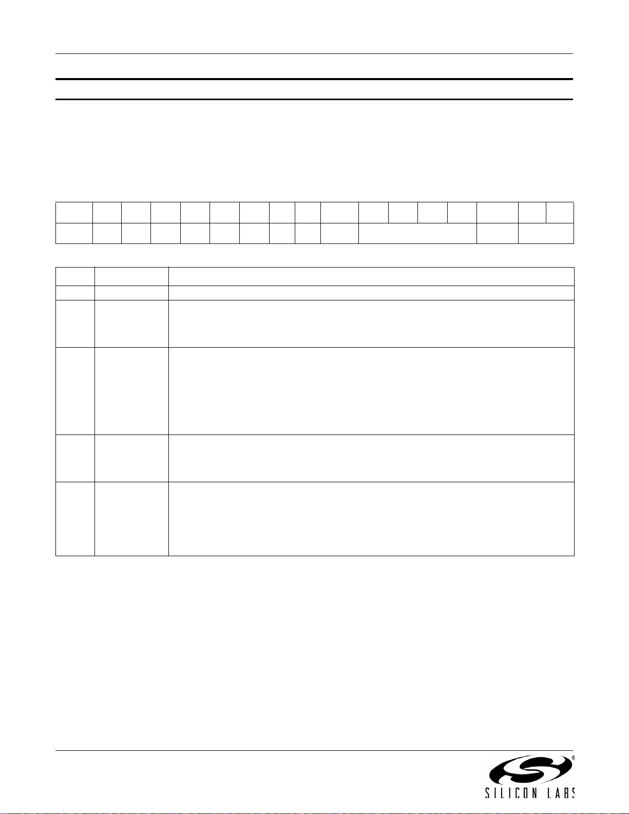
Property 0x0101. DIGITAL_INPUT_FORMAT
Configures the digital input format. The CTS bit (and optional interrupt) is set when it is safe to send the next
command. This property may only be set or read when in powerup mode.
Note: DIGITAL_INPUT_FORMAT is supported in FMTX component 2.0 or later.
Available in: All except Si4710-A10
Default: 0x0000
Bit D15 D14 D13 D12 D11 D10 D9 D8 D7 D6 D5 D4 D3 D2 D1 D0
Name 00000000IFALL IMODE[3:0] IMONOISIZE[1:0]
Bit Name Function
15:8 Reserved Always write to 0.
DCLK Falling Edge.
7IFALL
0 = Sample on DCLK rising edge (default).
1 = Sample on DCLK falling edge.
6:3 IMODE[3:0]
2IMONO
1:0 ISIZE[1:0]
Digital Mode.
0000 = default
0001 = I
0111 = Left-justified mode.
1101 = MSB at 1
1001 = MSB at 2
Mono Audio Mode.
0 = Stereo audio mode (default).
1 = Mono audio mode.
Digital Audio Sample Precision.
00 = 16 bits (default)
01 = 20 bits
10 = 24 bits
11 = 8 bits
2
S Mode.
st
DCLK rising edge after DFS Pulse.
nd
DCLK rising edge after DFS Pulse.
32 Rev. 0.8
Page 33
AN332
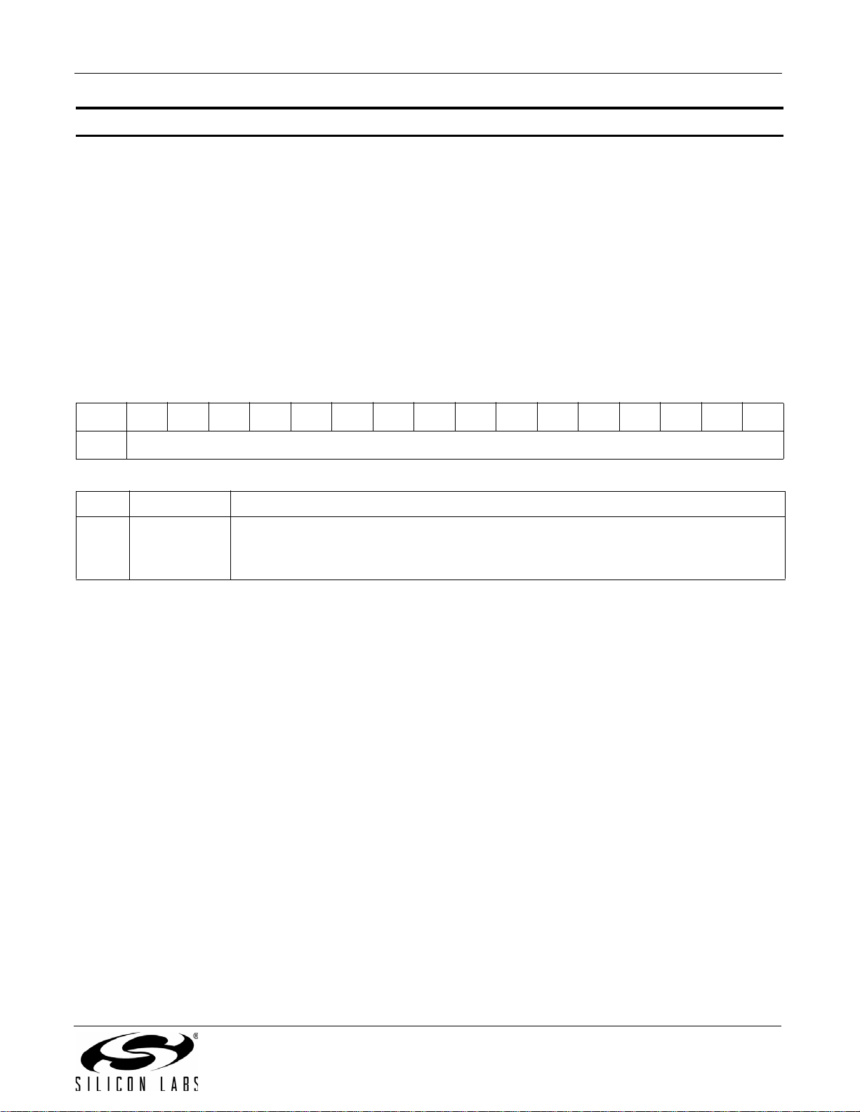
Property 0x0103. DIGITAL_INPUT_SAMPLE_RATE
Configures the digital input sample rate in 1 Hz units. The input sample rate must be set to 0 before removing the
DCLK input or reducing the DCLK frequency below 2 MHz. If this guideline is not followed, a device reset will be
required. The CTS bit (and optional interrupt) is set when it is safe to send the next command. This property may
only be set or read when in powerup mode. TX_TUNE_FREQ command must be sent after the POWER_UP
command to start the internal clocking before setting this property.
Note: DIGITAL_INPUT_SAMPLE_RATE is supported in FMTX component 2.0 or later.
Available in: All except Si4710-A10
Default: 0x0000
Units: 1 Hz
Step: 1 Hz
Range: 0, 32000-48000
BitD15D14D13D12D11D10D9D8D7D6D5D4D3D2D1D0
Name DISR[15:0]
Bit Name Function
Digital Input Sample Rate.
15:0 DISR
0 = Disabled. Required before removing DCLK or reducing DCLK frequency below
2 MHz. The range is 32000–48000 Hz.
Rev. 0.8 33
Page 34
AN332
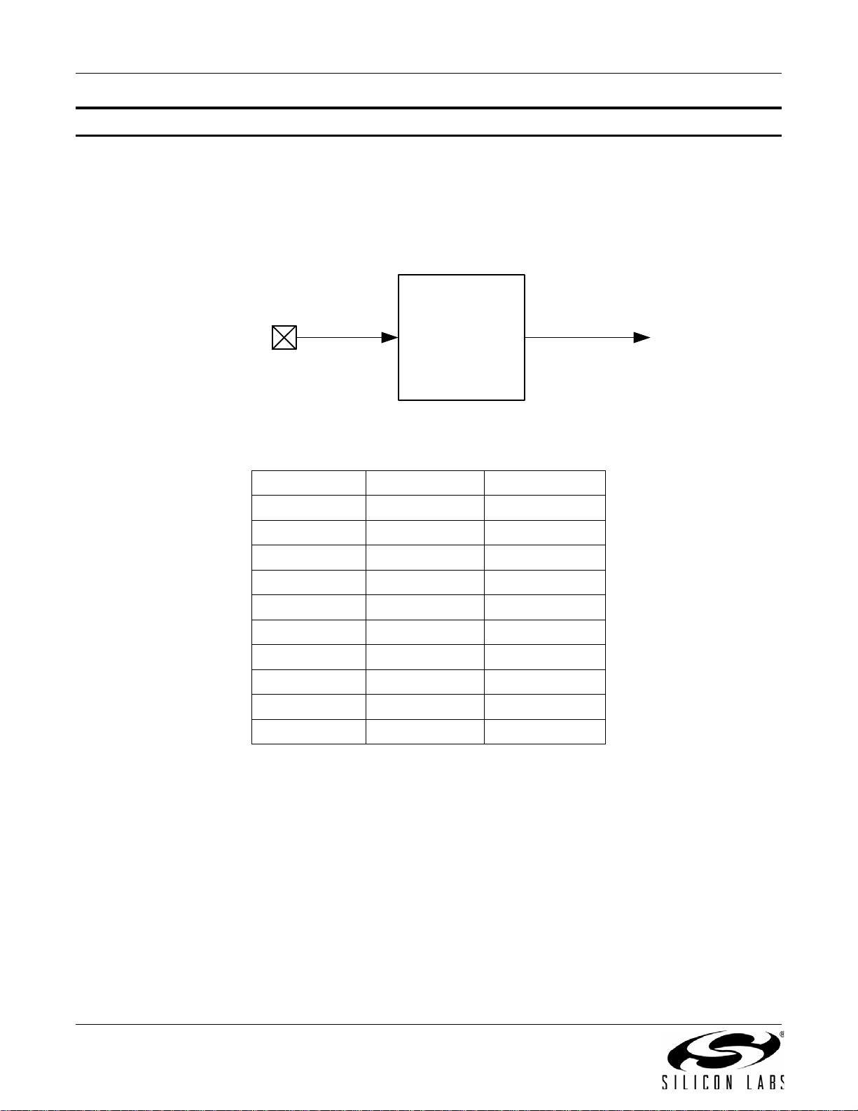
RCLK REFCLK
PIN 9
Prescaler
Divide by
1-4095
31.130 kHz –
40 MHz
31.130 kHz –
34.406 kHz
Property 0x0201. REFCLK_FREQ
Sets the frequency of the REFCLK from the output of the prescaler. (Figure 1 shows the relation between RCLK
and REFCLK.) The REFCLK range is 31130 to 34406 Hz (32768 ±5% Hz) in 1 Hz steps, or 0 (to disable AFC). For
example, an RCLK of 13 MHz would require a prescaler value of 400 to divide it to 32500 Hz REFCLK. The
reference clock frequency property would then need to be set to 32500 Hz. RCLK frequencies between 31130 Hz
and 40 MHz are supported, however, there are gaps in frequency coverage for prescaler values ranging from 1 to
10, or frequencies up to 311300 Hz. Table 7 summarizes these RCLK gaps.
Figure 1. REFCLK Prescaler
Table 7. RCLK Gaps
Prescaler RCLK Low (Hz) RCLK High (Hz)
1 31130 34406
2 62260 68812
3 93390 103218
4 124520 137624
5 155650 172030
6 186780 206436
7 217910 240842
8 249040 275248
9 280170 309654
10 311300 344060
The RCLK must be valid 10 ns before and 10 ns after sending the TX_TUNE_MEASURE, TX_TUNE_FREQ, or
TX_TUNE_POWER commands. In addition, the RCLK must be valid at all times when the carrier is enabled for
proper AFC operation. The RCLK may be removed or reconfigured at other times. The CTS bit (and optional
interrupt) is set when it is safe to send the next command. This property may only be set or read when in powerup
mode. The default is 32768 Hz.
Available in: All
Default: 0x8000 (32768)
Units: 1 Hz
Step: 1 Hz
Range: 31130–34406
34 Rev. 0.8
Page 35
AN332
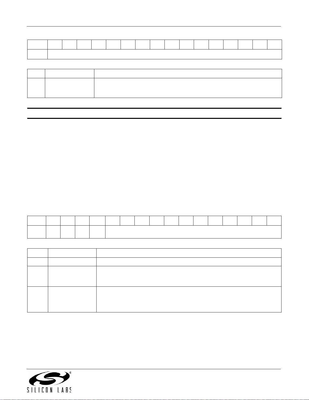
Bit D15D14D13D12D11D10D9D8D7D6D5D4D3D2D1D0
Name
Bit Name Function
Frequency of Reference Clock in Hz.
15:0 REFCLKF[15:0]
Property 0x0202. REFCLK_PRESCALE
Sets the number used by the prescaler to divide the external RCLK down to the internal REFCLK. The range may
be between 1 and 4095 in 1 unit steps. For example, an RCLK of 13 MHz would require a prescaler value of 400 to
divide it to 32500 Hz. The reference clock frequency property would then need to be set to 32500 Hz. The RCLK
must be valid 10 ns before and 10 ns after sending the TX_TUNE_MEASURE, TX_TUNE_FREQ, or
TX_TUNE_POWER commands. In addition, the RCLK must be valid at all times when the carrier is enabled for
proper AFC operation. The RCLK may be removed or reconfigured at other times. The CTS bit (and optional
interrupt) is set when it is safe to send the next command. This property may only be set or read when in powerup
mode. The default is 1.
Available in: All
Default: 0x0001
Step: 1
The allowed REFCLK frequency range is between 31130 and 34406 Hz (32768
±5%), or 0 (to disable AFC).
REFCLKF[15:0]
Range: 1–4095
BitD15D14D13D12D11D10D9D8D7D6D5D4D3D2D1D0
Name
Bit Name Function
15:13 Reserved Always write to 0.
12 RCLKSEL
11:0 R E FCLKP[ 11 :0]
000
RCLK
SEL
RCLKSEL.
0 = RCLK pin is clock source.
1 = DCLK pin is clock source.
Prescaler for Reference Clock.
Integer number used to divide the RCLK frequency down to REFCLK frequency.
The allowed REFCLK frequency range is between 31130 and 34406 Hz (32768
±5%), or 0 (to disable AFC).
RCLKP[11:0]
Rev. 0.8 35
Page 36
AN332
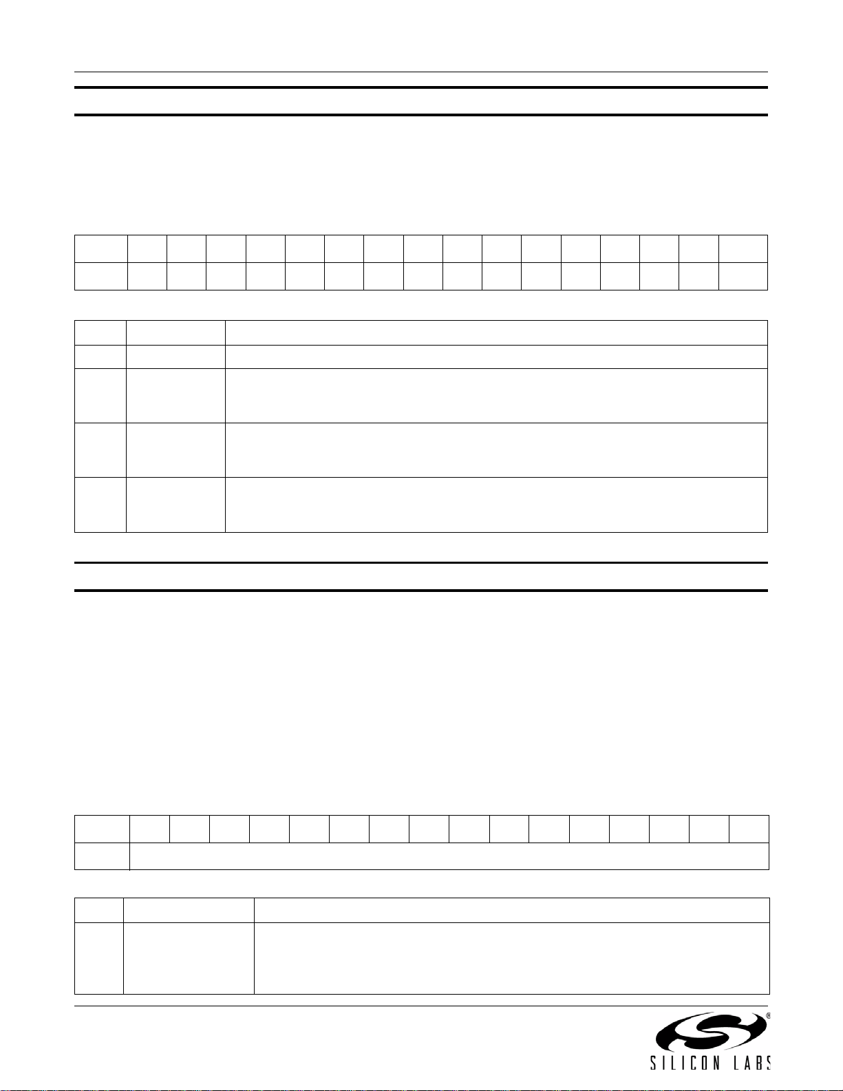
Property 0x2100. TX_COMPONENT_ENABLE
Individually enables the stereo pilot, left minus right stereo and RDS components. The CTS bit (and optional
interrupt) is set when it is safe to send the next command. This property may only be set or read when in powerup
mode. The default is stereo pilot and left minus right stereo components enabled.
Available in: All
Default: 0x0003
Bit D15D14D13D12D11D10D9D8D7D6D5D4D3D2D1 D0
Name
Bit Name Function
15:3 Reserved Always write 0.
2RDS
1LMR
0PILOT
Property 0x2101. TX_AUDIO_DEVIATION
Sets the transmit audio deviation from 0 to 90 kHz in 10 Hz units. The sum of the audio deviation, pilot deviation
and RDS deviation should not exceed regulatory requirements, typically 75 kHz. The CTS bit (and optional
interrupt) is set when it is safe to send the next command. This property may only be set or read when in powerup
mode. The default is 6825, or 68.25 kHz.
0000000000000RDSLMRPILOT
RDS Enable (Si4711/13/21 Only).
0 = Disables RDS (default).
1 = Enables RDS to be transmitted.
Left Minus Right.
0 = Disables Left Minus Right.
1 = Enables Left minus Right (Stereo) to be transmitted (default).
Pilot Tone.
0 = Disables Pilot.
1 = Enables the Pilot tone to be transmitted (default).
Available in: All
Default: 0x1AA9 (6825)
Units: 10 Hz
Step: 10 Hz
Range: 0–9000
Bit D15D14D13D12D11D10D9D8D7D6D5D4D3D2D1D0
Name
Bit Name Function
Transmit Audio Frequency Deviation.
15:0 TXADEV[15:0]
36 Rev. 0.8
Audio frequency deviation is programmable from 0 Hz to 90 kHz in 10 Hz units.
Default is 6825 (68.25 kHz). Note that the total deviation of the audio, pilot, and
RDS must be less than 75 kHz to meet regulatory requirements.
TXADEV[15:0]
Page 37
AN332
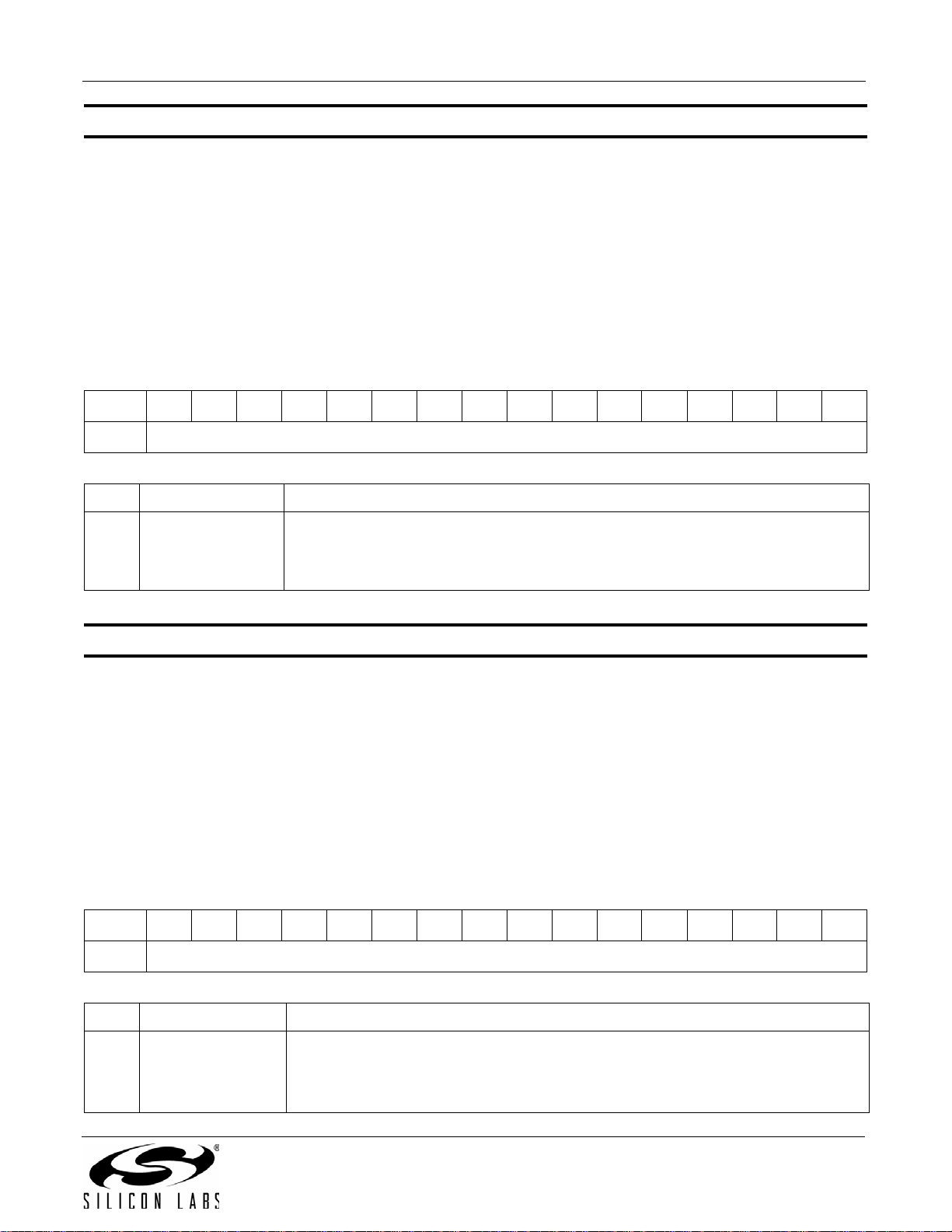
Property 0x2102. TX_PILOT_DEVIATION
Sets the transmit pilot deviation from 0 to 90 kHz in 10 Hz units. The sum of the audio deviation, pilot deviation and
RDS deviation should not exceed regulatory requirements, typically 75 kHz. The CTS bit (and optional interrupt) is
set when it is safe to send the next command. This property may only be set or read when in powerup mode. The
default is 675, or 6.75 kHz.
Available in: All
Default: 0x02A3 (675)
Units: 10 Hz
Step: 10 Hz
Range: 0–9000
Bit D15D14D13D12D11D10D9D8D7D6D5D4D3D2D1D0
Name
Bit Name Function
Transmit Pilot Frequency Deviation.
15:0 TXPDEV[15:0]
Property 0x2103. TX_RDS_DEVIATION
Sets the RDS deviation from 0 to 7.5 kHz in 10 Hz units. The sum of the audio deviation, pilot deviation and RDS
deviation should not exceed regulatory requirements, typically 75 kHz. The CTS bit (and optional interrupt) is set
when it is safe to send the next command. This property may only be set or read when in powerup mode. The
default is 200, or 2 kHz.
Available in: Si4711/13/21
Default: 0x00C8 (200)
Units: 10 Hz
Step: 10 Hz
Range: 0–9000
Pilot tone frequency deviation is programmable from 0 Hz to 90 kHz in 10 Hz units.
Default is 675 (6.75 kHz). Note that the total deviation of the audio, pilot, and RDS
must be less than 75 kHz to meet regulatory requirements.
TXPDEV[15:0]
Bit D15D14D13D12D11D10D9D8D7D6D5D4D3D2D1D0
Name
Bit Name Function
Transmit RDS Frequency Deviation.
15:0 TXRDEV[15:0]
RDS frequency deviation is programmable from 0 Hz to 90 kHz in 10 Hz units.
Default is 200 (2 kHz). Note that the total deviation of the audio, pilot, and RDS
must be less than 75 kHz to meet regulatory requirements.
TXRDEV[15:0]
Rev. 0.8 37
Page 38
AN332
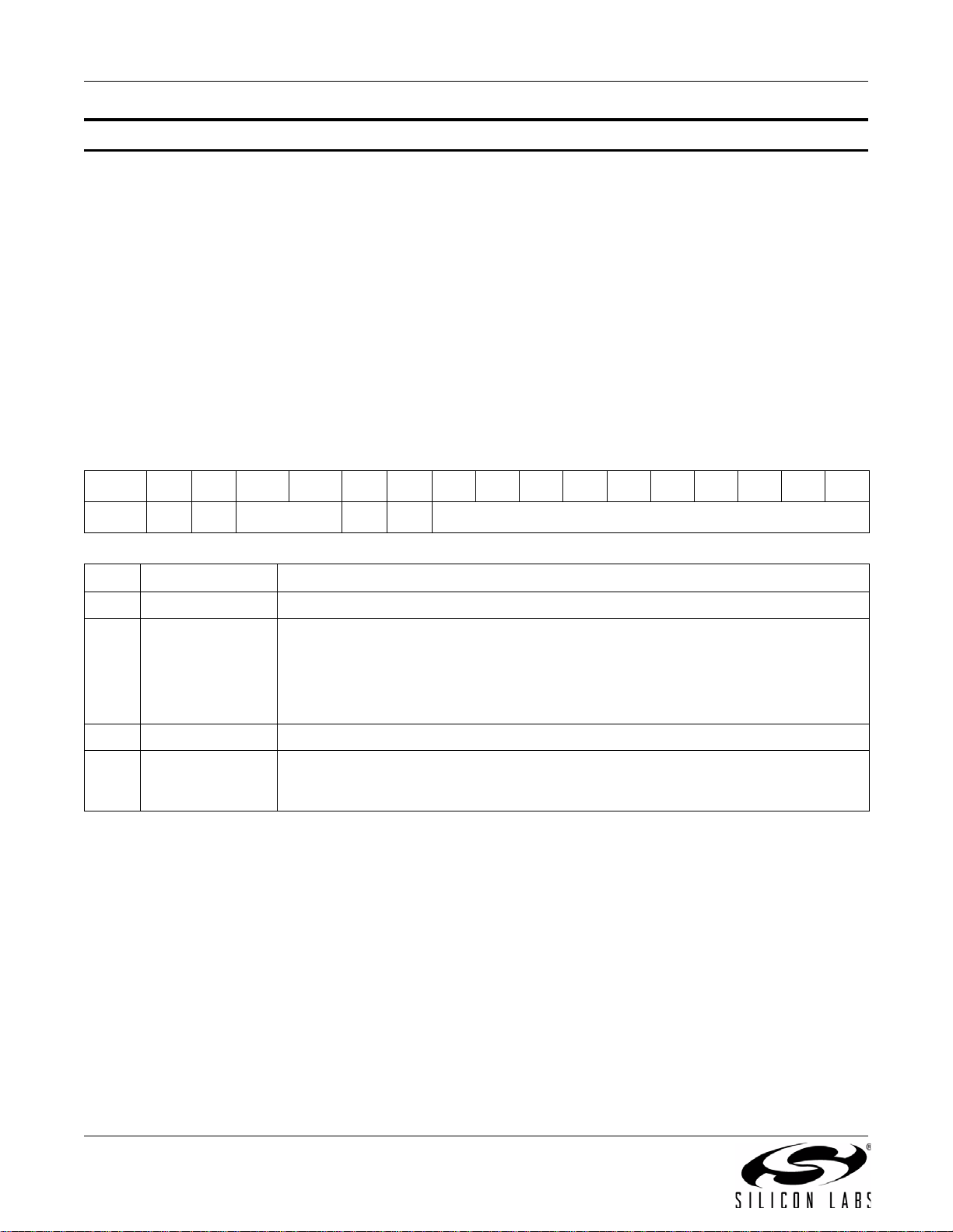
Property 0x2104. TX_LINE_INPUT_LEVEL
Sets the input resistance and maximum audio input level for the LIN/RIN pins. An application providing a 150 mV
PK
input to the device on RIN/LIN would set Line Attenuation = 00, resulting in a maximum permissible input level of
190 mV
the TX audio deviation level set by the TX_AUDIO_DEVIATION property. An application providing a 1 V
the device on RIN/LIN would set Line Attenuation = 11, resulting in a maximum permissible input level of 636 mV
on LIN/RIN and an input resistance of 396 k. The Line Level would be set to 150 mV to correspond to
PK
input to
PK
PK
on LIN/RIN and an input resistance of 60 k. An external series resistor on LIN and RIN inputs of 40 k would
create a resistive voltage divider that would keep the maximum line level on RIN/LIN below 636 mV
Level would be set to 636 mV
to correspond to the TX audio deviation level set by the TX_AUDIO_DEVIATION
PK
. The Line
PK
property. The CTS bit (and optional interrupt) is set when it is safe to send the next command. This property may
only be set or read when in powerup mode. The default input level and peak line level is 636 mV
impedance of 60 k
.
with an input
PK
Available in: All
Default: 0x327C
Bit D15D14D13D12D11D10D9D8D7D6D5D4D3D2D1D0
Name
0 0 LIATTEN[1:0] 0 0 LILEVEL[9:0]
Bit Name Function
15:14 Reserved Always write to 0.
Line Attenuation.
00 = Max input level = 190 mVPK; input resistance = 396 k
13:12 LIATTEN[1:0]
01 = Max input level = 301 mVPK; input resistance = 100 k
10 = Max input level = 416 mVPK; input resistance = 74 k
11 = Max input level = 636 mVPK; input resistance = 60 k(default)
11:10 Reserved Always write to 0.
Line Level.
9:0 LILEVEL[9:0]
Maximum line amplitude level on the LIN/RIN pins in mVPK. The default is 0x27C or
636 mV
PK
.
38 Rev. 0.8
Page 39
AN332
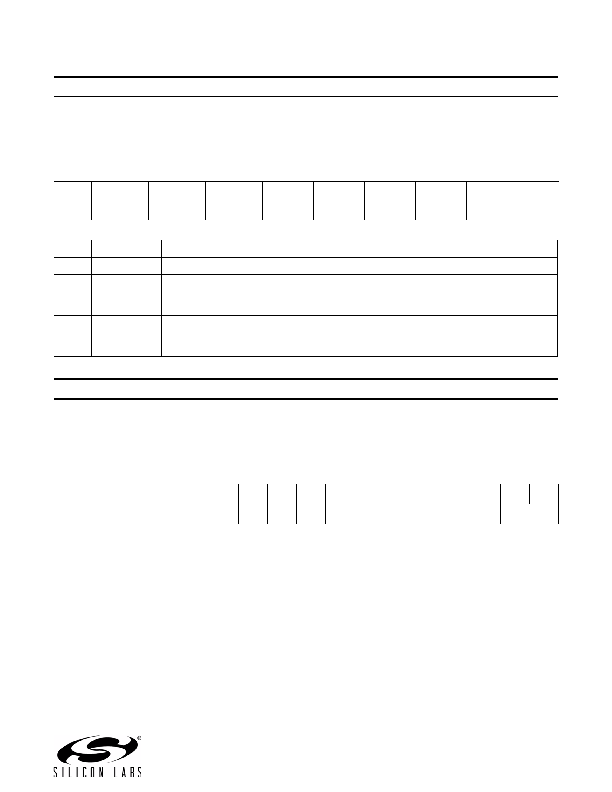
Property 0x2105. TX_LINE_INPUT_MUTE
Selectively mutes the left and right audio inputs. The CTS bit (and optional interrupt) is set when it is safe to send
the next command. This property may only be set or read when in powerup mode.
Available in: All
Default: 0x0000
Bit D15D14D13D12D11D10D9D8D7D6D5D4D3D2 D1 D0
Name
Bit Name Function
15:2 Reserved Always write to 0.
1LIMUTE
0RIMUTE
Property 0x2106. TX_PREEMPHASIS
Sets the transmit pre-emphasis to 50 µs, 75 µs or off. The CTS bit (and optional interrupt) is set when it is safe to
send the next command. This property may only be set or read when in powerup mode. The default is 75 µs.
Available in: All
Default: 0x0000
Bit D15D14D13D12D11D10D9D8D7D6D5D4D3D2D1D0
0 0 0 0 0 0 00000000LIMUTERIMUTE
Mutes L Line Input.
0 = No mute (default)
1=Mute
Mutes R Line Input.
0 = No mute (default)
1=Mute
Name
Bit Name Function
15:2 Reserved Always write to 0.
1:0 FMPE[1:0]
00000000000000FMPE[1:0]
FM Pre-Emphasis.
00 = 75 µs. Used in USA (default)
01 = 50 µs. Used in Europe, Australia, Japan
10 = Disabled
11 = Reser v e d
Rev. 0.8 39
Page 40
AN332
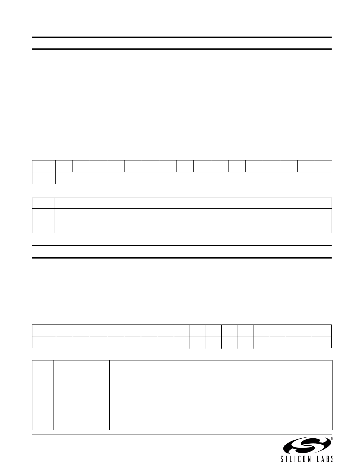
Property 0x2107. TX_PILOT_FREQUENCY
This property is used to set the frequency of the stereo pilot in 1 Hz steps. The stereo pilot is nominally set to
19 kHz for stereo operation, however the pilot can be set to any frequency from 0 Hz to 19 kHz to support the
generation of an audible test tone. The pilot tone is enabled by setting the PILOT bit (D0) of the
TX_COMPONENT_ENABLE property. When using the stereo pilot as an audible test generator it is recommended
that the RDS bit (D2) be disabled. The CTS bit (and optional interrupt) is set when it is safe to send the next
command. This property may only be set or read when in powerup mode.
Available in: All
Default: 0x4A38 (19000)
Units: 1 Hz
Step: 1 Hz
Range: 0–19000
Bit D15D14D13D12D11D10D9D8D7D6D5D4D3D2D1D0
Name
Bit Name Function
Stereo Pilot Frequency
15:0 FREQ
Property 0x2200. TX_ACOMP_ENABLE
Selectively enables the audio dynamic range control and limiter. The CTS bit (and optional interrupt) is set when it
is safe to send the next command. This property may only be set or read when in powerup mode. The default is
limiter enabled and audio dynamic range control disabled.
Note: LIMITEN bit is supported in FMTX component 2.0 or later. Reset this bit to 0 in FMTX component 1.0.
Available in: All
Default: 0x0002
Bit D15 D14 D13 D12 D11 D10 D9 D8 D7 D6 D5 D4 D3 D2 D1 D0
Name
00000000000000LIMITENACEN
Sets the frequency of the stereo pilot in 1 Hz steps.
Range 0 Hz–19000 Hz (default is 0x4A38 or 19 kHz).
FREQ[15:0]
Bit Name Function
15:2 Reserved Always write to 0.
Audio Limiter.
1 LIMITEN
0ACEN
40 Rev. 0.8
0=Disable
1 = Enable (default)
Transmit Audio Dynamic Range Control Enable.
0 = Audio dynamic range control disabled (default)
1 = Audio dynamic range control enabled
Page 41
AN332
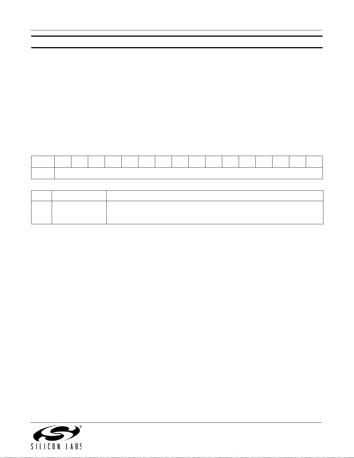
Property 0x2201. TX_ACOMP_THRESHOLD
Sets the threshold for audio dynamic range control from 0 dBFS to –40 dBFS in 1 dB units in 2's complement
notation. For example, a setting of –40 dB would be 65536 – 40 = 65496 = 0xFFD8. The threshold is the level
below which the device applies the gain set by the TX_ACOMP_GAIN property, and above which the device
applies the compression defined by (gain + threshold) / threshold. The CTS bit (and optional interrupt) is set when
it is safe to send the next command. This property may only be set or read when in powerup mode. The default is
0xFFD8, or –40 dBFS.
Available in: All
Default: 0xFFD8 (–40)
Units: 1 dB
Step: 1 dB
Range: –40 to 0
Bit D15D14D13D12D11D10D9D8D7D6D5D4D3D2D1D0
Name
Bit Name Function
Transmit Audio Dynamic Range Control Threshold.
15:0 THRESHOLD[15:0]
Range is from –40 to 0 dBFS in 1 dB steps (0xFFD8–0x0).
Default is 0xFFD8 (–40 dBFS).
THRESHOLD[15:0]
Rev. 0.8 41
Page 42
AN332
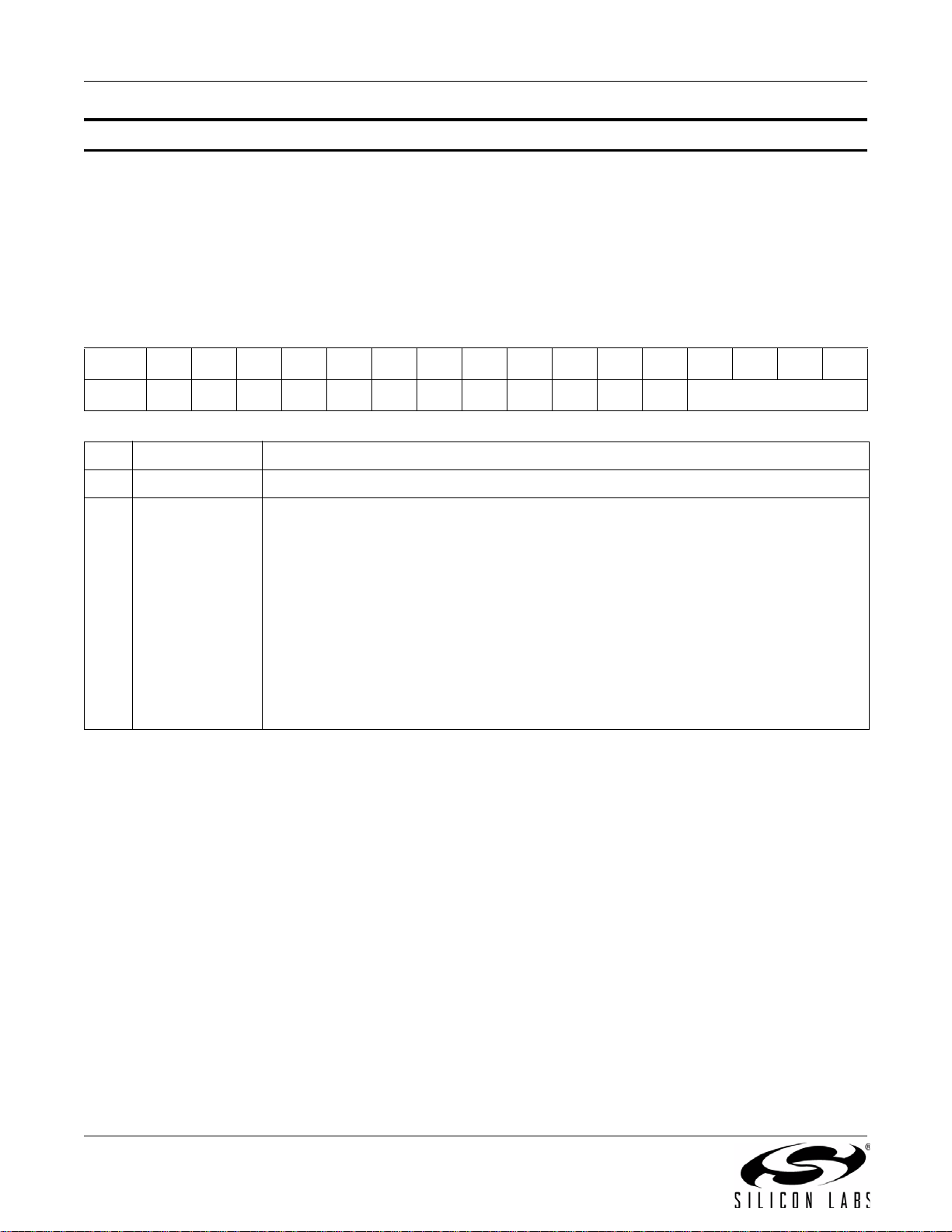
Property 0x2202. TX_ACOMP_ATTACK_TIME
Sets the time required for the device to respond to audio level transitions from below the threshold in the gain
region to above the threshold in the compression region. The CTS bit (and optional interrupt) is set when it is safe
to send the next command. This property may only be set or read when in powerup mode. The default is 0.5 ms, or
0.
Available in: All
Default: 0x0000
Range: 0–9
Bit D15D14D13D12D11D10D9D8D7D6D5D4D3D2D1D0
Name
Bit Name Function
15:4 Reserved Always write to 0.
3:0 ATTACK[3:0]
000000000000 ATTACK[3:0]
Transmit Audio Dynamic Range Control Attack Time.
0 = 0.5 ms (default)
1 = 1.0 ms
2 = 1.5 ms
3 = 2.0 ms
4 = 2.5 ms
5 = 3.0 ms
6 = 3.5 ms
7 = 4.0 ms
8 = 4.5 ms
9 = 5.0 ms
42 Rev. 0.8
Page 43
AN332
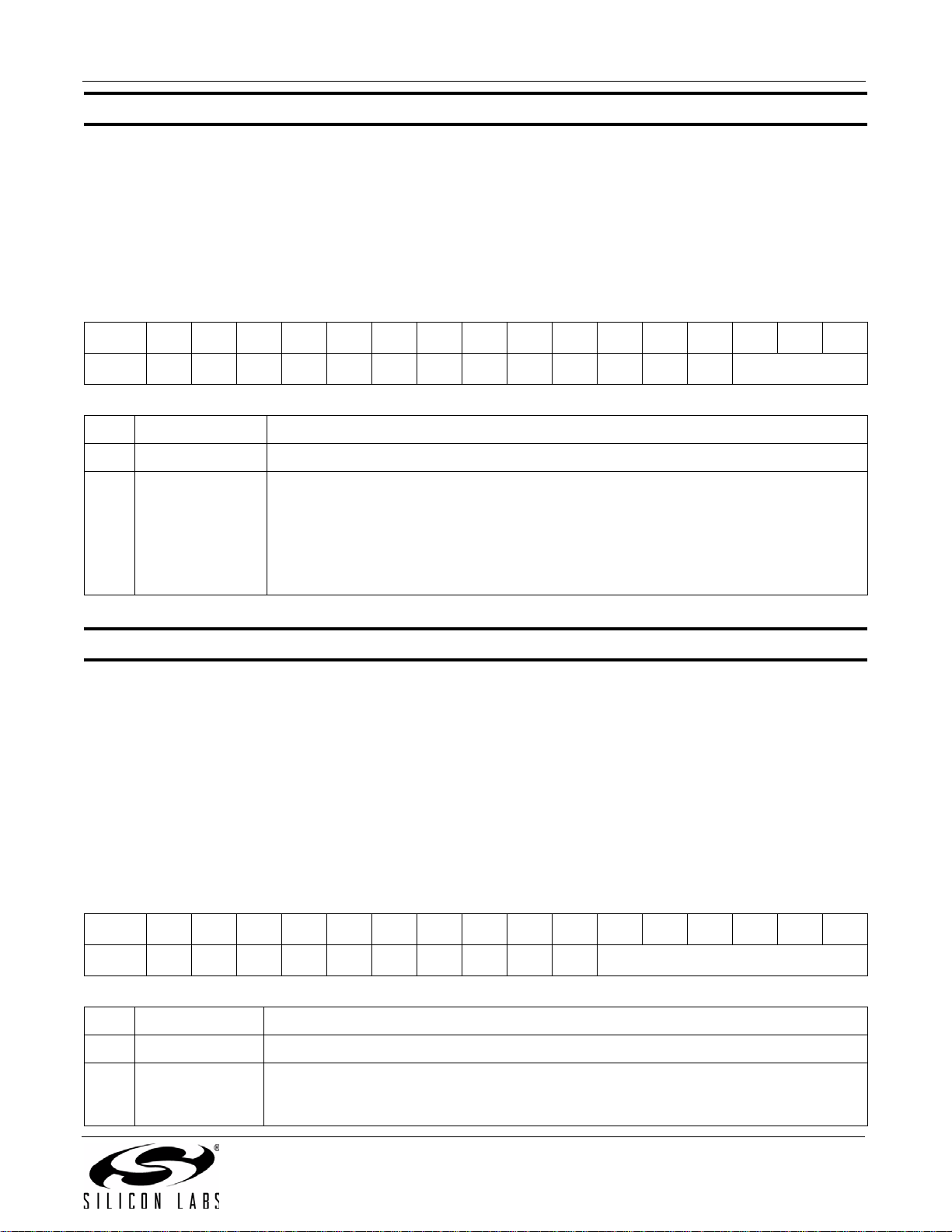
Property 0x2203. TX_ACOMP_RELEASE_TIME
Sets the time required for the device to respond to audio level transitions from above the threshold in the
compression region to below the threshold in the gain region. The CTS bit (and optional interrupt) is set when it is
safe to send the next command. This property may only be set or read when in powerup mode. The default is
1000 ms, or 4.
Available in: All
Default: 0x0004
Range: 0–4
Bit D15D14D13D12D11D10D9D8D7D6D5D4D3D2D1D0
Name
Bit Name Function
15:3 Reserved Always write to 0.
2:0 RELEASE[2:0]
Property 0x2204. TX_ACOMP_GAIN
Sets the gain for audio dynamic range control from 0 to 20 dB in 1 dB units. For example, a setting of 15 dB would
be 15 = 0xF. The gain is applied to the audio below the threshold set by the TX_ACOMP_THRESHOLD property.
The CTS bit (and optional interrupt) is set when it is safe to send the next command. This property may only be set
or read when in powerup mode. The default is 15 dB or 0xF.
Available in: All
Default: 0x000F (15)
0000000000000RELEASE[2:0]
Transmit Audio Dynamic Range Control Release Time.
0 = 100 ms
1 = 200 ms
2 = 350 ms
3 = 525 ms
4 = 1000 ms (default)
Units: 1 dB
Step: 1 dB
Range: 0–20
Bit D15D14D13D12D11D10D9D8D7D6D5D4D3D2D1D0
Name
Bit Name Function
15:6 Reserved Always write to 0.
Transmit Audio Dynamic Range Control Gain.
5:0 GAIN[5:0]
Range is from 0 to 20 dB in 1 dB steps.
Default is 15.
Rev. 0.8 43
GAIN[5:0]
Page 44

AN332
Property 0x2205. TX_LIMITER_RELEASE_TIME
Sets the time required for the device to respond to audio level transitions from above the limiter threshold to below
the limiter threshold. The CTS bit (and optional interrupt) is set when it is safe to send the next command. This
property may only be set or read when in powerup mode. The default is 5.01 ms, or 102.
Note: TX_LIMITER_RELEASE_TIME is supported in FMTX component 2.0 or later.
Available in: All except Si4710-A10
Default 0x0066 (102)
Step: 1
Range: 5–2000
Bit D15D14D13D12D11D10D9D8D7D6D5D4D3D2D1D0
Name
Bit Name Function
Sets the limiter release time.
5 = 102.39 ms
6 = 85.33 ms
7 = 73.14 ms
8 = 63.99 ms
10 = 51.19 ms
13 = 39.38 ms
17 = 30.11 ms
25 = 20.47 ms
51 = 10.03 ms
15:0 LMITERTC[15:0]
57 = 8.97 ms
64 = 7.99 ms
73 = 7.01 ms
85 = 6.02 ms
102 = 5.01 ms (default)
127 = 4.02 ms
170 = 3.00 ms
255 = 2.00 ms
510 = 1.00 ms
1000 = 0.50 ms
2000 = 0.25 ms
LIMITERTC[15:0]
44 Rev. 0.8
Page 45
AN332
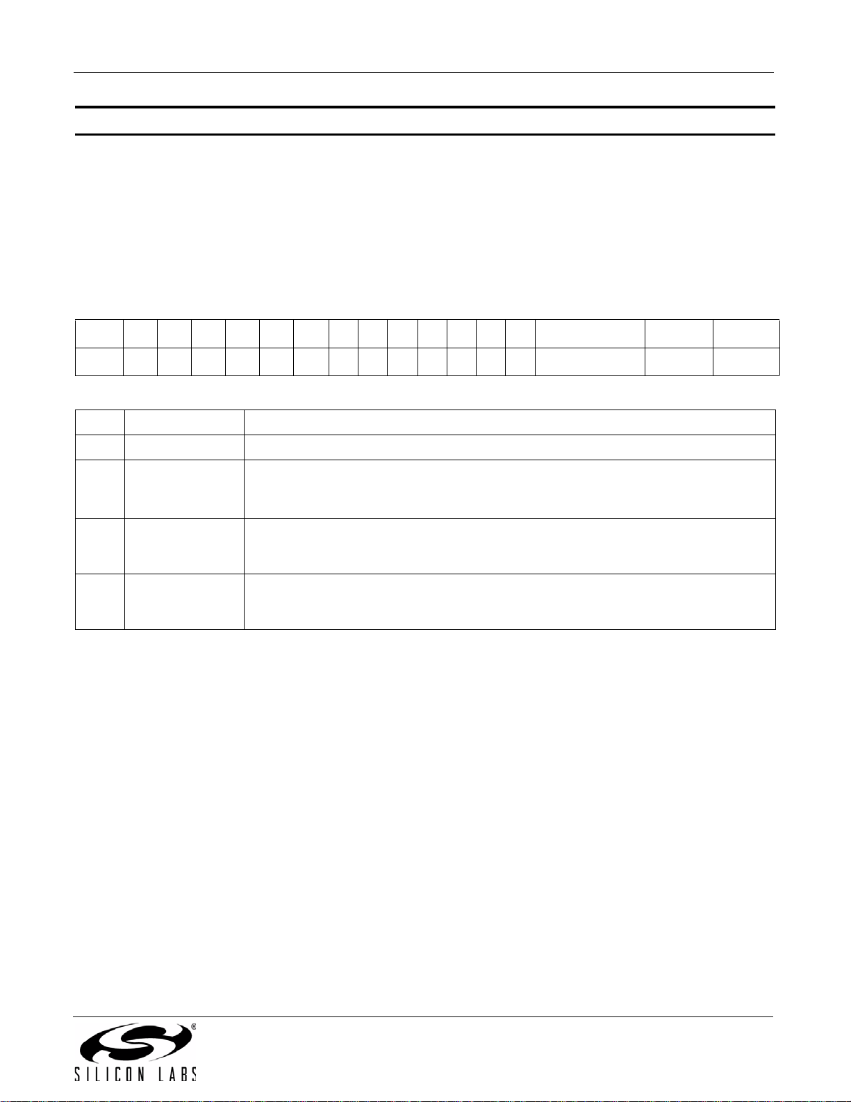
Property 0x2300. TX_ASQ_INTERRUPT_SELECT
This property is used to enable which Audio Signal Quality (ASQ) measurements trigger ASQ_INT bit in the
TX_ASQ_STATUS command. OVERMODIEN bit enables ASQ interrupt by the OVERMOD bit, which turns on with
overmodulation of the FM output signal due to excessive input signal level. IALHIEN and IALLIEN bits enable ASQ
interrupt by the IALH and IALL bits, which report high or low input audio condition. The CTS bit (and optional
interrupt) is set when it is safe to send the next command. This property may only be set or read when in powerup
mode.
Available in: All
Default: 0x0000
Bit D15 D14 D13 D12 D11 D10 D9 D8 D7 D6 D5 D4 D3 D2 D1 D0
Name
Bit Name Function
15:3 Reserved Always write to 0.
0 0 0 0 0 0 0000000OVERMODIENIALHIENIALLIEN
Overmodulation Detection Enable.
2 OVERMODIEN
1 IALHIEN
0 IALLIEN
0 = OVERMOD detect disabled (default).
1 = OVERMOD detect enabled.
Input Audio Level Detection High Threshold Enable.
0 = IALH detect disabled (default).
1 = IALH detect enabled.
Input Audio Level Detection Low Threshold Enable.
0 = IALL detect disabled (default).
1 = IALL detect enabled.
Rev. 0.8 45
Page 46
AN332
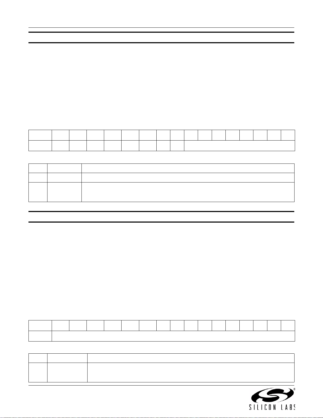
Property 0x2301. TX_ASQ_LEVEL_LOW
This property sets the low audio level threshold relative to 0 dBFS in 1 dB increments, which is used to trigger the
IALL bit. This threshold can be set to detect a silence condition in the input audio allowing the host to take an
appropriate action such as disabling the RF carrier or powering down the chip. The CTS bit (and optional interrupt)
is set when it is safe to send the next command. This property may only be set or read when in powerup mode. The
default is 0x0000 and the range is 0 to –70.
Available in: All
Default: 0x0000
Units: 1 dB
Step: 1 dB
Range: –70 to 0
Bit D15D14D13D12 D11D10D9D8D7D6D5D4D3D2D1D0
Name
Bit Name Function
15:8 Reserved Always write to 0.
7:0 IALLTH[7:0]
Property 0x2302. TX_ASQ_DURATION_LOW
This property is used to determine the duration (in 1 ms increments) that the input signal must be below the
TX_ASQ_LEVEL_LOW threshold in order for an IALL condition to be generated. The range is 0 ms to 65535 ms,
and the default is 0 ms. Note that the TX_ASQ_DURATION_LOW and TX_ASQ_DURATION_HIGH counters start
and the TX_ASQ_STATUS command will only return valid data after a call to TX_TUNE_FREQ,
TX_TUNE_POWER, or TX_TUNE_MEASURE. The CTS bit (and optional interrupt) is set when it is safe to send
the next command. This property may only be set or read when in powerup mode.
Available in: All
Default: 0x0000
Units: 1 ms
00000000 IALLTH[7:0]
Input Audio Level Low Threshold.
Threshold which input audio level must be below in order to detect a low audio condition.
Specified in units of dBFS in 1 dB steps (–70 .. 0). Default is 0.
Step: 1 ms
Range: 0–65535
Bit D15D14D13D12 D11D10D9D8D7D6D5D4D3D2D1D0
Name
Bit Name Function
Input Audio Level Duration Low.
15:0 IALLDUR[15:0]
46 Rev. 0.8
Required duration the input audio level must fall below IALLTH to trigger an IALL interrupt. Specified in 1mS increments (0–65535 ms). Default is 0.
IALLDUR[15:0]
Page 47
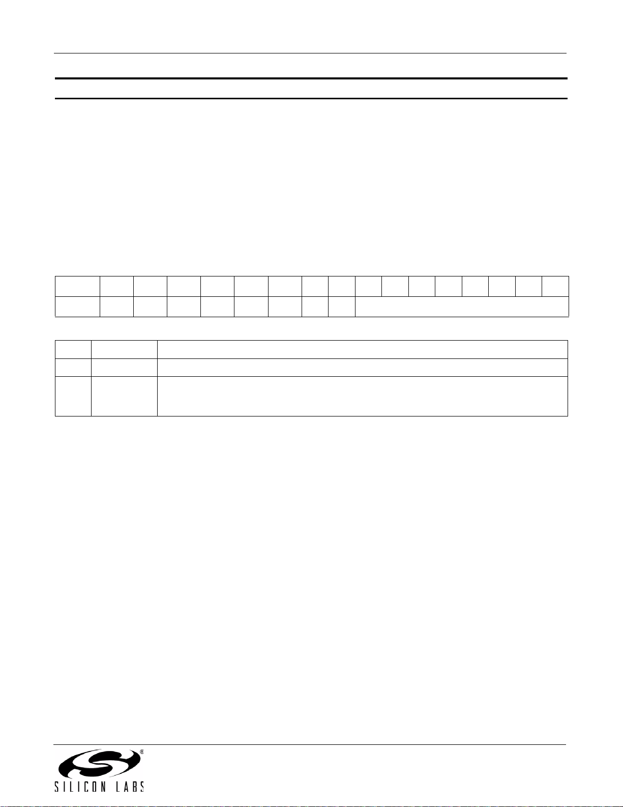
AN332
Property 0x2303. TX_ASQ_LEVEL_HIGH
This property sets the high audio level threshold relative to 0 dBFS in 1 dB increments, which is used to trigger the
IALH bit. This threshold can be set to detect an activity condition in the input audio allowing the host to take an
appropriate action such as enabling the RF carrier after an extended silent period. The CTS bit (and optional
interrupt) is set when it is safe to send the next command. This property may only be set or read when in powerup
mode. The default is 0x0000 and the range is 0 to –70.
Available in: All
Default: 0x0000
Units: 1 dB
Step: 1 dB
Range: –70 to 0
Bit D15D14D13D12 D11D10D9D8D7D6D5D4D3D2D1D0
Name
Bit Name Function
15:8 Reserved Always write to 0.
7:0 IALHTH[7:0]
00000000 IALHTH[7:0]
Input Audio Level High Threshold
Threshold which input audio level must be above in order to detect a high audio condition.
Specified in units of dBFS in 1 dB steps (–70 .. 0). Default is 0.
Rev. 0.8 47
Page 48
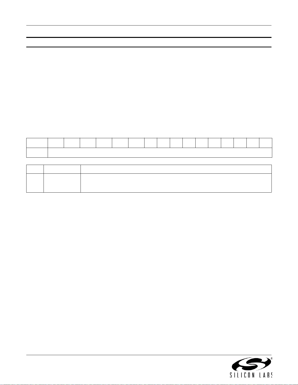
AN332
Property 0x2304. TX_ASQ_DURATION_HIGH
This property is used to determine the duration (in 1 ms increments) that the input signal must be above the
TX_ASQ_LEVEL_HIGH threshold in order for a IALH condition to be generated. The range is 0 to 65535 ms, and
the default is 0 ms. Note that the TX_ASQ_DURATION_LOW and TX_ASQ_DURATION_HIGH counters start and
the TX_ASQ_STATUS command will only return valid data after a call to TX_TUNE_FREQ, TX_TUNE_POWER,
or TX_TUNE_MEASURE. The CTS bit (and optional interrupt) is set when it is safe to send the next command.
This property may only be set or read when in powerup mode.
Available in: All
Default: 0x0000
Units: 1 ms
Step: 1 ms
Range: 0–65535
Bit D15D14D13D12 D11D10D9D8D7D6D5D4D3D2D1D0
Name
Bit Name Function
Input Audio Level Duration High.
15:0 IALHDUR[15:0]
Required duration the input audio level must exceed IALHTH to trigger an IALH interrupt. Specified in 1 ms increments (0 – 65535 ms). Default is 0.
IALHDUR[15:0]
48 Rev. 0.8
Page 49
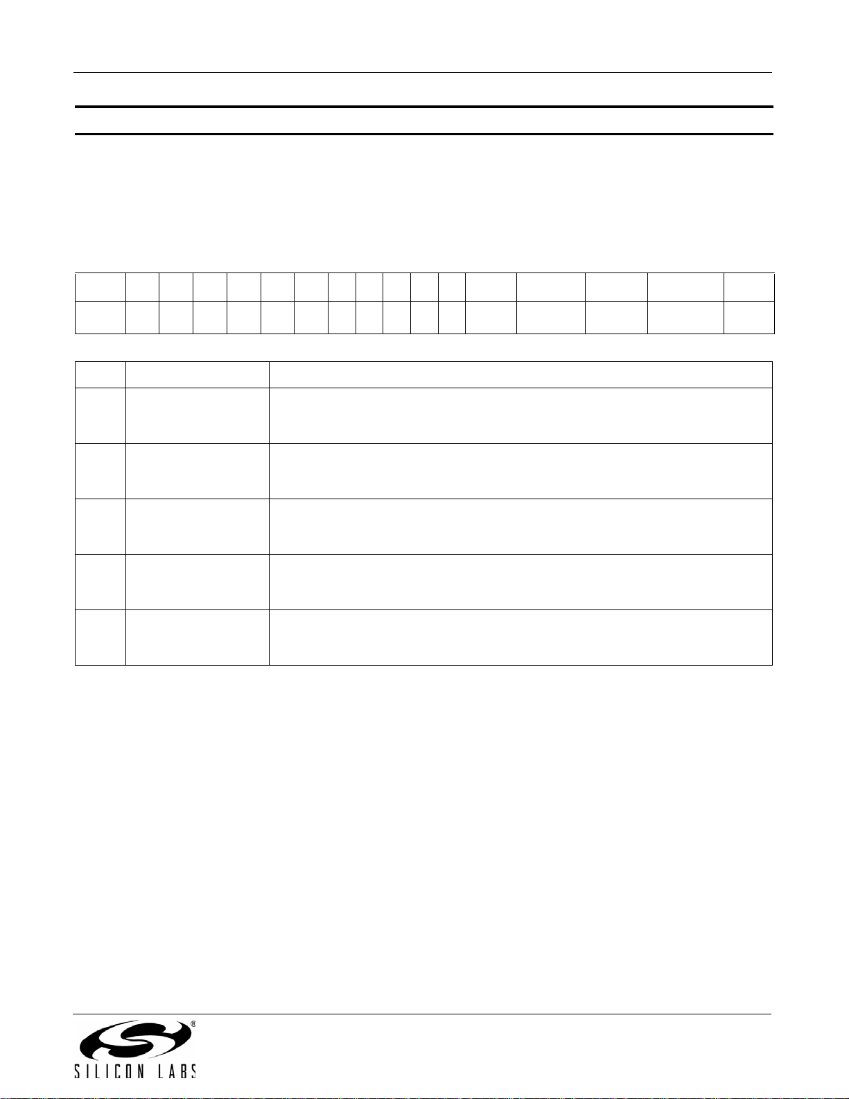
AN332
Property 0x2C00. TX_RDS_INTERRUPT_SOURCE
Configures the RDS interrupt sources. The CTS bit (and optional interrupt) is set when it is safe to send the next
command. This property may only be set or read when in powerup mode.
Note: TX_RDS_INTERRUPT_SOURCE is supported in FMTX component 2.0 or later.
Available in: Si4711/13/21
Default: 0x0000
Bit D15 D14 D13 D12 D11 D10 D9 D8 D7 D6 D5 D4 D3 D2 D1 D0
Name
00000000000
RDS
PSXMIT
CBUFXMIT
Bit Name Function
0 = Do not interrupt (default).
4 RDSPSXMIT
1 = Interrupt when a RDS PS Group has been transmitted. The interrupt occurs
when a PS group begins transmission.
0 = Do not interrupt (default).
3 RDSCBUFXMIT
1 = Interrupt when a RDS Group has been transmitted from the Circular Buffer.
The interrupt occurs when a group is fetched from the buffer.
0 = Do not interrupt (default).
2 RDSFIFOXMIT
1 = Interrupt when a RDS Group has been transmitted from the FIFO Buffer. The
interrupt occurs when a group is fetched from the buffer.
0 = Do not interrupt (default).
1 RDSCBUFWRAP
1 = Interrupt when the RDS Group Circular Buffer has wrapped. The interrupt
occurs when the last group is fetched from the buffer.
0 = Do not interrupt (default).
0 RDSFIFOMT
1 = Interrupt when the RDS Group FIFO Buffer is empty. The interrupt occurs
when the last group is fetched from the FIFO.
RDS
RDS-
FIFOXMIT
RDS
CBUFWRAP
RDSFI-
FOMT
Rev. 0.8 49
Page 50
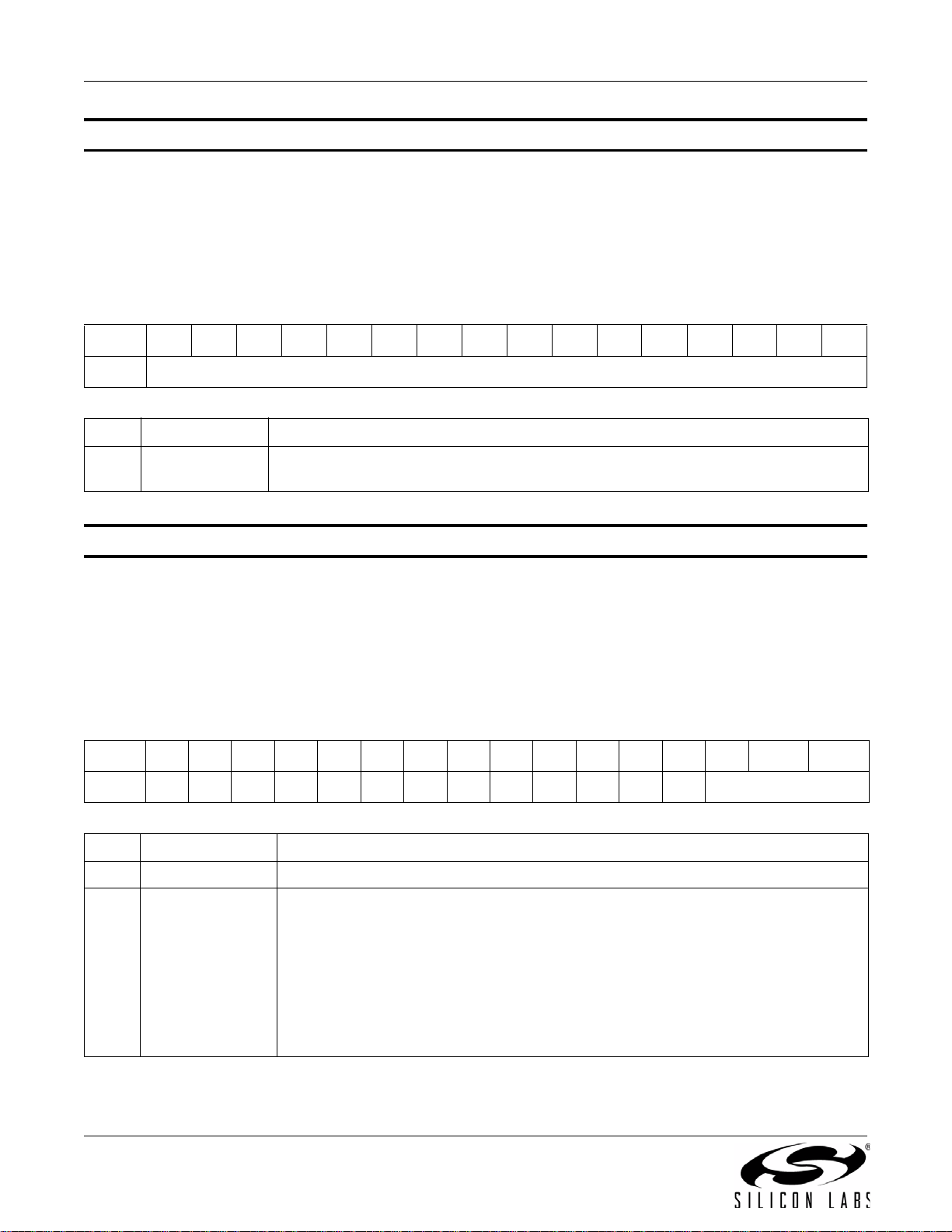
AN332
Property 0x2C01. TX_RDS_PI
Sets the RDS PI code to be transmitted in block A and block C (for type B groups). The CTS bit (and optional
interrupt) is set when it is safe to send the next command. This property may only be set or read when in powerup
mode.
Note: TX_RDS_PI is supported in FMTX component 2.0 or later.
Available in: Si4711/13/21
Default: 0x40A7
Bit D15D14D13D12D11D10D9D8D7D6D5D4D3D2D1D0
Name
Bit Name Function
15:0 RDSPI[15:0]
Property 0x2C02. TX_RDS_PS_MIX
Sets the ratio of RDS PS (group 0A) and circular buffer/FIFO groups. The CTS bit (and optional interrupt) is set
when it is safe to send the next command. This property may only be set or read when in powerup mode.
Note: TX_RDS_PS_MIX is supported in FMTX component 2.0 or later.
Available in: Si4711/13/21
Default: 0x0003
Range: 0–6
Bit D15D14D13D12D11D10D9D8D7D6D5D4D3D2 D1 D0
Name
0000000000000 RDSPSMIX[2:0]
Transmit RDS Program Identifier.
RDS program identifier data.
RDSPI[15:0]
Bit Name Function
15:3 Reserved Always write to 0.
Transmit RDS Mix.
000 = Only send RDS PS if RDS Group Buffer is empty
001 = Send RDS PS 12.5% of the time
2:0 RDSPSMIX[2:0]
50 Rev. 0.8
010 = Send RDS PS 25% of the time
011 = Send RDS PS 50% of the time (default)
100 = Send RDS PS 75% of the time
101 = Send RDS PS 87.5% of the time
110 = Send RDS PS 100% of the time
Page 51
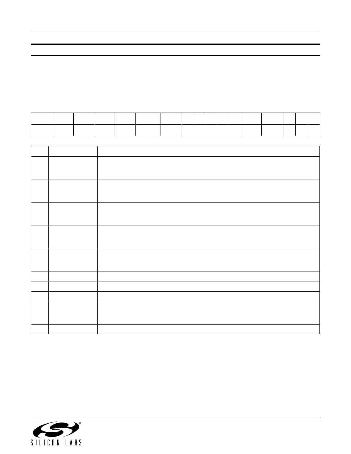
AN332
Property 0x2C03. TX_RDS_PS_MISC
Configures miscellaneous RDS flags. The CTS bit (and optional interrupt) is set when it is safe to send the next
command. This property may only be set or read when in powerup mode.
Note: TX_RDS_PS_MISC is supported in FMTX component 2.0 or later.
Available in: Si4711/13/21
Default: 0x1008
Bit D15 D14 D13 D12 D11 D10 D9D8D7D6D5 D4 D3 D2D1D0
Name
Bit Name Function
9:5 RDSPTY[4:0] Program Type Code (default = 0).
2:0 Reserved Always write to 0.
RDSD3 RDSD2 RDSD1 RDSD0 FORCEB RDSTP RDSPTY[4:0] RDSTA RDSMS 0 0 0
Dynamic PTY code.
15 RDSD3
14 RDSD2
13 RDSD1
12 RDSD0
11 FORCEB
10 RDSTP
4RDSTATraffic Announcement Code (default = 0).
3RDSMS
0 = Static PTY (default).
1 = Indicates that the PTY code is dynamically switched.
Compressed code.
0 = Not compressed (default).
1 = Compressed.
Artificial Head code.
0 = Not artificial head (default).
1 = Artificial head.
Mono/Stereo code.
0 = Mono.
1 = Stereo (default).
Use the PTY and TP set here in all block B data.
0 = FIFO and BUFFER use PTY and TP as when written (default).
1 = FIFO and BUFFER force PTY and TP to be the settings in this property.
Traffic Program Code (default = 0).
Music/Speech Switch Code.
0 = Speech.
1 = Music (default).
Rev. 0.8 51
Page 52
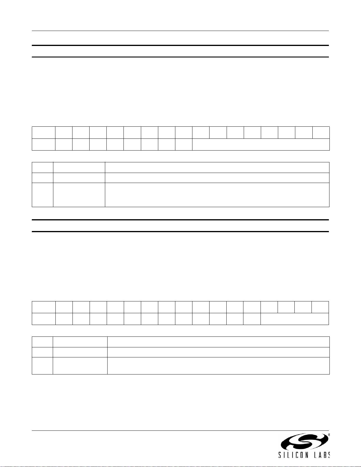
AN332
Property 0x2C04. TX_RDS_PS_REPEAT_COUNT
Sets the number of times a program service group 0A is repeated. The CTS bit (and optional interrupt) is set when
it is safe to send the next command. This property may only be set or read when in powerup mode.
Note: TX_RDS_PS_REPEAT_COUNT is supported in FMTX component 2.0 or later.
Available in: Si4711/13/21
Default: 0x0003
Range: 1–255
Bit D15D14D13D12D11D10D9D8D7D6D5D4D3D2D1D0
Name
Bit Name Function
15:8 Reserved Always write to 0.
7:0 RDSPSRC[7:0]
Property 0x2C05. TX_RDS_PS_MESSAGE_COUNT
Sets the number of program service messages through which to cycle. The CTS bit (and optional interrupt) is set
when it is safe to send the next command. This property may only be set or read when in powerup mode.
Note: TX_RDS_PS_MESSAGE_COUNT is supported in FMTX component 2.0 or later.
Available in: Si4711/13/21
Default: 0x0001
Range 1–12
Bit D15D14D13D12D11D10D9D8D7D6D5D4D3D2D1D0
00000000 RDSPSRC[7:0]
Transmit RDS PS Repeat Count.
Number of times to repeat transmission of a PS message before transmitting the
next PS message.
Name
Bit Name Function
15:4 Reserved Always write to 0.
3:0 RDSPSMC[3:0]
52 Rev. 0.8
000000000000 RDSPSMC[3:0]
Transmit RDS PS Message Count.
Number of PS messages to cycle through. Default is 1.
Page 53
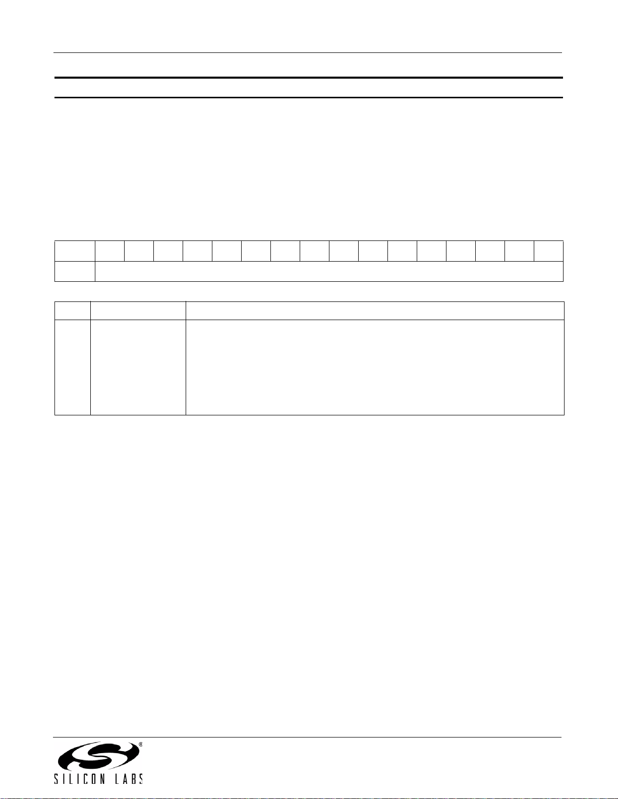
AN332
Property 0x2C06. TX_RDS_PS_AF
Sets the AF RDS Program Service Alternate Frequency. This provides the ability to inform the receiver of a single
alternate frequency using AF Method A coding and is transmitted along with the RDS_PS Groups. The CTS bit
(and optional interrupt) is set when it is safe to send the next command. This property may only be set or read
when in powerup mode.
Note: TX_RDS_PS_AF is supported in FMTX component 2.0 or later.
Available in: Si4711/13/21
Default: 0xE0E0
Range: 0xE000–0xE0CC
Bit D15D14D13D12D11D10D9D8D7D6D5D4D3D2D1D0
Name
Bit Name Function
Transmit RDS Program Service Alternate Frequency.
0xE101 = 1 AF @ 87.6 MHz
0xE102 = 1 AF @ 87.7 MHz
15:0 RDSAF[15:0]
...
0xE1CB = 1 AF @ 107.8 MHz
0xE1CC = 1 AF @ 107.9 MHz
0xE0E0 = No AF exists (default)
RDSAF[15:0]
Rev. 0.8 53
Page 54
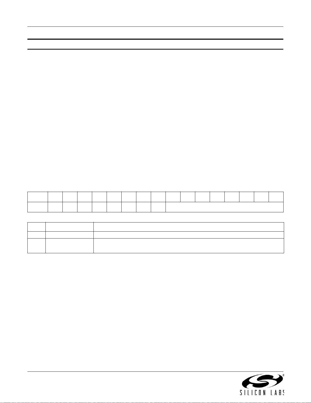
AN332
Property 0x2C07. TX_RDS_FIFO_SIZE
Sets the RDS FIFO size in number of blocks. Note that the value written must be one larger than the desired FIFO
size. The number of blocks allocated will reduce the size of the Circular RDS Group Buffer by the same amount.
For instance, if RDSFIFOSZ = 20, then the RDS Circular Buffer will be reduced by 20 blocks. The minimum
number of blocks which should be allocated is 4. This provides enough room for a single group of any type (xA or
xB) to be transmitted. Groups xA require 3 Blocks, Groups xB require 2 Blocks as block C' is always the same as
the RDS PI code. Before setting this value, determine the available blocks through the TX_RDS_FIFO command,
as the buffer size may vary between versions or part numbers. The guaranteed minimum FIFO size, however, is 53
blocks. The RDS FIFO and the RDS Circular Buffer should be emptied with the TX_RDS_FIFO command prior to
changing the size of the FIFO. The CTS bit (and optional interrupt) is set when it is safe to send the next command.
This property may only be set or read when in powerup mode.
Note: TX_RDS_FIFO_SIZE is supported in FMTX component 2.0 or later.
Available in: Si4711/13/21
Default: 0x0000
Units: blocks
Step: 3 blocks
Range: 0, 4, 7, 10–54
Note: Actual maximum FIFO size returned by the TX_RDS_BUFF command is larger, however, this is 53 blocks is
the guaranteed FIFO size.
Bit D15D14D13D12D11D10D9D8D7D6D5D4D3D2D1D0
Name
Bit Name Function
15:8 Reserved Always write 0.
7:0 RDSFIFOSZ[7:0]
00000000 RDSFIFOSZ[7:0]
Transmit RDS FIFO Size.
0 = FIFO disabled (default)
54 Rev. 0.8
Page 55

AN332
5.2. Commands and Properties for the FM/RDS Receiver (Si4704/05/06/2x/3x/4x/84/85)
Tables 8 and 9 summarize the commands and properties for the FM/RDS Receiver component applicable to
Si4704/05/06/2x/3x/4x/84/85.
Table 8. FM/RDS Receiver Command Summary
Cmd Name Description Available In
0x01 POWER_UP Power up device and mode selection.
0x10 GET_REV Returns revision information on the device.
0x11 POWER_DOWN Power down device.
0x12 SET_PROPERTY Sets the value of a property.
0x13 GET_PROPERTY Retrieves a property’s value.
0x14 GET_INT_STATUS Reads interrupt status bits.
0x15 PATCH_ARGS* Reserved command used for patch file downloads.
0x16 PATCH_DATA* Reserved command used for patch file downloads.
0x20 FM_TUNE_FREQ Selects the FM tuning frequency.
0x21 FM_SEEK_START Begins searching for a valid frequency.
0x22 FM_TUNE_STATUS
0x23 FM_RSQ_STATUS
0x24 FM_RDS_STATUS
0x27 FM_AGC_STATUS Queries the current AGC settings
0x28 FM_AGC_OVERRIDE Override AGC setting by disabling and forcing it to a fixed value
0x80 GPIO_CTL Configures GPO1, 2, and 3 as output or Hi-Z.
0x81 GPIO_SET Sets GPO1, 2, and 3 output level (low or high).
*Note: Commands PATCH_ARGS and PATCH_DATA are only used to patch firmware. For information on applying a patch file, see
"7.2. Powerup from a Component Patch" on page 234.
Queries the status of previous FM_TUNE_FREQ or
FM_SEEK_START command.
Queries the status of the Received Signal Quality (RSQ) of the current
channel.
Returns RDS information for current channel and reads an entry from
RDS FIFO
.
Si4731/35/37/39,
All
All
All
All
All
All
All
All
All
All
All
All
Si4705/06,
Si4721, Si474x,
Si4785
All
All
All except
Si4730-A10
All except
Si4730-A10
Rev. 0.8 55
Page 56

AN332
Table 9. FM/RDS Receiver Property Summary
Prop Name Description Default
0x0001 GPO_IEN Enables interrupt sources. 0x0000 All
0x0102
0x0104
0x0201 REFCLK_FREQ
0x0202 REFCLK_PRESCALE Sets the prescaler value for RCLK input. 0x0001 All
0x1100 FM_DEEMPHASIS
0x1102 FM_CHANNEL_FILTER
DIGITAL_OUTPUT_
FORMAT
DIGITAL_OUTPUT_
SAMPLE_RATE
Configure digital audio outputs. 0x0000
Configure digital audio output sample rate. 0x0000
Sets frequency of reference clock in Hz.
The range is 31130 to 34406 Hz, or 0 to
disable the AFC. Default is 32768 Hz.
Sets deemphasis time constant. Default is
75 µs.
Selects bandwidth of channel filter applied
at the demodulation stage.
0x8000 All
0x0002 All except Si4749
0x0001
0x0000
AvailableIn
Si4705/06,
Si4721/31/35/37/
39,
Si4730/34/36/38-
D60 and later,
Si4741/43/45,
Si4784/85
Si4705/06,
Si4721/31/35/37/
39,
Si4730/34/36/38-
D60 and later,
Si4741/43/45,
Si4784/85
Si4706, Si4749,
Si4705/31/35/85-
D50 and later
Si4704/30/34/84-
D50 and later
0x1105
0x1106
0x1107 FM_ANTENNA_INPUT
0x1108
0x1200
0x1201
56 Rev. 0.8
FM_BLEND_STEREO_
THRESHOLD
FM_BLEND_MONO_
THRESHOLD
FM_MAX_TUNE_
ERROR
FM_RSQ_INT_
SOURCE
FM_RSQ_SNR_HI_
THRESHOLD
Selects bandwidth of channel filter applied
at the demodulation stage.
Sets RSSI threshold for mono blend (Full
mono below threshold, blend above
threshold). To force stereo set this to 0. To
force mono set this to 127. Default value is
30 dBµV.
Selects the antenna type and the pin to
which it is connected.
Sets the maximum freq error allowed
before setting the AFC rail (AFCRL) indicator. Default value is 20 kHz.
Configures interrupt related to Received
Signal Quality metrics.
Sets high threshold for SNR interrupt. 0x007F All
Si470x/2x,
0x0031
0x001E
0x0000
0x001E All
0x0014 All others
0x0000 All
Si473x-C40 and
earlier
Si470x/2x,
Si473x-C40 and
earlier
Si4704/05/06/20/
21
Page 57

Table 9. FM/RDS Receiver Property Summary (Continued)
AN332
Prop Name Description Default
0x1202
0x1203
0x1204
0x1205
0x1206
0x1207
0x1300 FM_SOFT_MUTE_RATE
0x1301 FM_SOFT_MUTE_SLOPE
0x1302
0x1303
0x1304
FM_RSQ_SNR_LO_
THRESHOLD
FM_RSQ_RSSI_HI_
THRESHOLD
FM_RSQ_RSSI_LO_
THRESHOLD
FM_RSQ_MULTIPATH_HI_
THRESHOLD
FM_RSQ_MULTIPATH_
LO_THRESHOLD
FM_RSQ_BLEND_
THRESHOLD
FM_SOFT_MUTE_
MAX_ATTENUATION
FM_SOFT_MUTE_
SNR_THRESHOLD
FM_SOFT_MUTE_
RELEASE_RATE
Sets low threshold for SNR interrupt. 0x0000 All
Sets high threshold for RSSI interrupt. 0x007F All
Sets low threshold for RSSI interrupt. 0x0000 All
Sets high threshold for multipath interrupt. 0x007F
Sets low threshold for multipath interrupt. 0x0000
Sets the blend threshold for blend interrupt
when boundary is crossed.
Sets the attack and decay rates when
entering and leaving soft mute.
Configures attenuation slope during soft
mute in dB attenuation per dB SNR below
the soft mute SNR threshold. Default value
is 2.
Sets maximum attenuation during soft
mute (dB). Set to 0 to
disable soft mute. Default is 16 dB.
Sets SNR threshold to engage soft mute.
Default is 4 dB.
Sets soft mute release rate. Smaller values
provide slower release, and larger values
provide faster release. The default is 8192
(approximately 8000 dB/s)
0x0081 All except Si4749
0x0040
0x0002
0x0010 All except Si4749
0x0004 All except Si4749
0x2000
AvailableIn
Si4706-C30 and
later,
Si474x,
Si4704/05/30/31/
34/35/84/85-D50
and later
Si4706-C30 and
later,
Si474x,
Si4704/05/30/31/
34/35/84/85-D50
and later
Si4706/07/20/21/
84/85-B20 and
earlier,
Si4704/05/3x-
C40 and earlier
Si4704/05/06/3x-
C40 and later,
Si4740/41/42/43/
44/45
Si4706-C30 and
later,
Si4740/41/42/43/
44/45,
Si4704/05/30/31/
34/35/84/85-D50
and later
Rev. 0.8 57
Page 58

AN332
Table 9. FM/RDS Receiver Property Summary (Continued)
Prop Name Description Default
Sets soft mute attack rate. Smaller values
0x1305
0x1400
0x1401 FM_SEEK_BAND_TOP
0x1402
0x1403
0x1404
0x1500 FM_RDS_INT_SOURCE Configures RDS interrupt behavior. 0x0000
0x1501
0x1502 FM_RDS_CONFIG Configures RDS setting. 0x0000
0x1503 FM_RDS_CONFIDENCE
0x1700 FM_AGC_ATTACK_RATE
0x1701 FM_AGC_RELEASE_RATE
FM_SOFT_MUTE_
ATTACK _ RATE
FM_SEEK_BAND_
BOTTOM
FM_SEEK_FREQ_
SPACING
FM_SEEK_TUNE_
SNR_THRESHOLD
FM_SEEK_TUNE_
RSSI_TRESHOLD
FM_RDS_INT_FIFO_
COUNT
provide slower attack, and larger values
provide faster attack. The default is 8192
(approximately 8000 dB/s)
Sets the bottom of the FM band for seek.
Default is 8750 (87.5 MHz).
Sets the top of the FM band for seek.
Default is 10790 (107.9 MHz).
Selects frequency spacing for FM seek.
Default value is 10 (100 kHz).
Sets the SNR threshold for a valid FM
Seek/Tune.
Default value is 3 dB.
Sets the RSSI threshold for a valid FM
Seek/Tune.
Default value is 20 dBµV.
Sets the minimum number of RDS groups
stored in the receive FIFO required before
RDSRECV is set.
Sets the confidence level threshold for
each RDS block.
Sets the AGC attack rate. Larger values
provide slower attack and smaller values
provide faster attack. The default is 4
(approximately 1500 dB/s).
Sets the AGC release rate. Larger values
provide slower release and smaller values
provide faster release. The default is 140
(approximately 43 dB/s).
0x2000
0x222E All
0x2A26 All
0x000A All
0x0003 All
0x0014 All
0x0000
0x1111
0x0004 Si474x
0x008C Si474x
AvailableIn
Si4706-C30 and
later,
Si4740/41/42/43/
44/45,
Si4704/05/30/31/
34/35/84/85-D50
and later
Si4705/06,
Si4721,
Si431/35/37/39,
Si4741/43/45/49
Si4705/06,
Si4721,
Si431/35/37/39,
Si4741/43/45/49
Si4705/06,
Si4721,
Si431/35/37/39,
Si4741/43/45/49
Si4706-C30 and
later, Si474x,
Si4704/05/30/31/
34/35/84/85-D50
and later
58 Rev. 0.8
Page 59

Table 9. FM/RDS Receiver Property Summary (Continued)
AN332
Prop Name Description Default
Sets RSSI threshold for stereo blend. (Full
stereo above threshold, blend below
threshold.) To force stereo, set this to 0. To
force mono, set this to 127. Default value is
49 dBμV.
Sets RSSI threshold for mono blend (Full
mono below threshold, blend above
threshold). To force stereo, set this to 0. To
force mono, set this to 127. Default value is
30 dBμV.
Sets the stereo to mono attack rate for
RSSI based blend. Smaller values provide
slower attack and larger values provide
faster attack. The default is 4000 (approximately 16 ms).
Sets the mono to stereo release rate for
RSSI based blend. Smaller values provide
slower release and larger values provide
faster release. The default is 400 (approximately 164 ms).
Sets SNR threshold for stereo blend (Full
stereo above threshold, blend below
threshold). To force stereo, set this to 0. To
force mono, set this to 127. Default value is
27 dB.
Sets SNR threshold for mono blend (Full
mono below threshold, blend above
threshold). To force stereo, set this to 0. To
force mono, set this to 127. Default value is
14 dB.
0x0031
0x001E
0x0FA0
0x0190
0x001B
0x000E
0x1800
0x1801
0x1802
0x1803
0x1804
0x1805
FM_BLEND_RSSI_
STEREO_THRESHOLD
FM_BLEND_RSSI_MONO_
THRESHOLD
FM_BLEND_RSSI_
ATTACK _ RATE
FM_BLEND_RSSI_
RELEASE_RATE
FM_BLEND_SNR_
STEREO_THRESHOLD
FM_BLEND_SNR_MONO_
THRESHOLD
AvailableIn
Si4706-C30 and
later,
Si4740/41/42/43/
44/45,
Si4705/31/35/85-
D50 and later
Si4706-C30 and
later,
Si4740/41/42/
43/44/45,
Si4705/31/35/85
-D50 and later
Si4706-C30 and
later,
Si4740/41/42/
43/44/45,
Si4705/31/35/85
-D50 and later
Si4706-C30 and
later,
Si4740/41/42/
43/44/45,
Si4705/31/35/85
-D50 and later
Si4740/41/42/43/
44/45,
Si4704/05-D50
and later,
Si4706-C30 and
later ,
Si4730/31/34/35/
84/85-D50 and
later
Si4740/41/42/43/
44/45,
Si4704/05-D50
and later,
Si4706-C30 and
later ,
Si4730/31/34/35/
84/85-D50 and
later
Rev. 0.8 59
Page 60

AN332
Table 9. FM/RDS Receiver Property Summary (Continued)
Prop Name Description Default
Sets the stereo to mono attack rate for
SNR based blend. Smaller values provide
slower attack and larger values provide
faster attack. The default is 4000 (approximately 16 ms).
Sets the mono to stereo release rate for
SNR based blend. Smaller values provide
slower release and larger values provide
faster release. The default is 400 (approximately 164 ms).
Sets multipath threshold for stereo blend
(Full stereo below threshold, blend above
threshold). To force stereo, set this to 100.
To force mono, set this to 0. Default value
is 20.
0x0FA0
0x0190
0x0014
0x1806
0x1807
0x1808
FM_BLEND_SNR_ATTACK_
RATE
FM_BLEND_SNR_
RELEASE_RATE
FM_BLEND_MULTIPATH_
STEREO_THRESHOLD
AvailableIn
Si4740/41/42/
43/44/45,
Si4704/05-D50
and later,
Si4706-C30 and
later ,
Si4730/31/34/35
/84/85-D50 and
later
Si4740/41/42/
43/44/45,
Si4704/05-D50
and later,
Si4706-C30 and
later ,
Si4730/31/34/35
/84/85-D50 and
later
Si4740/41/42/
43/44/45,
Si4704/05-D50
and later,
Si4706-C30 and
later ,
Si4730/31/34/35/
84/85-D50 and
later
Sets Multipath threshold for mono blend
0x1809
0x180A
60 Rev. 0.8
FM_BLEND_MULTIPATH_M
ONO_THRESHOLD
FM_BLEND_MULTIPATH_
ATTACK _ RATE
(Full mono above threshold, blend below
threshold). To force stereo, set to 100. To
force mono, set to 0. The default is 60.
Sets the stereo to mono attack rate for Multipath based blend. Smaller values provide
slower attack and larger values provide
faster attack. The default is 4000 (approximately 16 ms).
0x003C
0x0FA0
Si4740/41/42/43/
44/45,
Si4704/05-D50
and later,
Si4706-C30 and
later ,
Si4730/31/34/35/
84/85-D50 and
later
Si4740/41/42/43/
44/45,
Si4704/05-D50
and later,
Si4706-C30 and
later ,
Si4730/31/34/35/
84/85-D50 and
later
Page 61

Table 9. FM/RDS Receiver Property Summary (Continued)
AN332
Prop Name Description Default
Sets the mono to stereo release rate for
0x180B
0x180C
0x1900
0x1901 FM_NB_INTERVAL
0x1902 FM_NB_RATE
0x1903 FM_NB_IIR_FILTER
0x1904 FM_NB_DELAY
0x1A00
0x1A01
FM_BLEND_MULTIPATH_
RELEASE_RATE
FM_BLEND_MAX_STEREO
_SEPARATION
FM_NB_DETECT_
THRESHOLD
FM_HICUT_ SNR_HIGH_
THRESHOLD
FM_HICUT_
SNR_LOW_THRESHOLD
Multipath based blend. Smaller values provide slower release and larger values provide faster release. The default is 40
(approximately 1.64 s).
Sets the maximum amount of stereo
separation
Sets the threshold for detecting impulses in
dB above the noise floor. Default value is
16.
Interval in micro-seconds that original samples are replaced by interpolated clean
samples. Default value is 24 µs.
Noise blanking rate in 100 Hz units. Default
value is 64.
Sets the bandwidth of the noise floor estimator Default value is 300.
Delay in micro-seconds before applying
impulse blanking to the original samples.
Default value is 133.
Sets the SNR level at which hi-cut begins
to band limit. Default value is 24.
Sets the SNR level at which hi-cut reaches
maximum band limiting. Default value is
15.
0x0028
0x0000 Si474x
0x0010 Si4742/43/44/45
0x0018 Si4742/43/44/45
0x0040 Si4742/43/44/45
0x012C Si4742/43/44/45
0x00AA Si4742/43/44/45
0x0018
0x000F
AvailableIn
Si4740/41/42/43/
44/45,
Si4704/05-D50
and later,
Si4706-C30 and
later ,
Si4730/31/34/35/
84/85-D50 and
later
Si4740/41/42/43/
44/45,
Si4704/05-D50
and later,
Si4706-C30 and
later ,
Si4730/31/34/35/
84/85-D50 and
later
Si4740/41/42/43/
44/45,
Si4704/05-D50
and later,
Si4706-C30 and
later ,
Si4730/31/34/35/
84/85-D50 and
later
Rev. 0.8 61
Page 62

AN332
Table 9. FM/RDS Receiver Property Summary (Continued)
Prop Name Description Default
Sets the rate at which hi-cut lowers the cut-
0x1A02 FM_HICUT_ ATTACK_RATE
0x1A03
0x1A04
0x1A05
0x1A06
0x4000 RX_VOLUME Sets the output volume. 0x003F All except Si4749
0x4001 RX_HARD_MUTE
FM_HICUT_
RELEASE_RATE
FM_HICUT_
MULTIPATH_TRIGGER
THRESHOLD
FM_HICUT_
MULTIPATH_END_
THRESHOLD
FM_HICUT_
CUTOFF_FREQUENCY
off frequency. Default value is 20000
(approximately 3 ms)
Sets the rate at which hi-cut increases the
cut-off frequency. Default value is 20.
(approximately 3.3 s)
Sets the MULTIPATH level at which hi-cut
begins to band limit. Default value is 20.
Sets the MULTIPATH level at which hi-cut
reaches maximum band limiting. Default
value is 60.
Sets the maximum band limit frequency for
hi-cut and also sets the maximum audio
frequency. Default value is 0 (disabled).
Mutes the audio output. L and R audio outputs may be muted independently.
0x4E20
0x0014
0x0014
0x003C
0x0000
0x0000 All except Si4749
AvailableIn
Si4740/41/42/43/
44/45,
Si4704/05-D50
and later,
Si4706-C30 and
later ,
Si4730/31/34/35/
84/85-D50 and
later
Si4740/41/42/43/
44/45,
Si4704/05-D50
and later,
Si4706-C30 and
later ,
Si4730/31/34/35/
84/85-D50 and
later
Si4740/41/42/43/
44/45,
Si4704/05-D50
and later,
Si4706-C30 and
later ,
Si4730/31/34/35/
84/85-D50 and
later
Si4740/41/42/43/
44/45,
Si4704/05-D50
and later,
Si4706-C30 and
later ,
Si4730/31/34/35/
84/85-D50 and
later
Si4740/41/42/43/
44/45,
Si4704/05-D50
and later,
Si4706-C30 and
later ,
Si4730/31/34/35/
84/85-D50 and
later
62 Rev. 0.8
Page 63
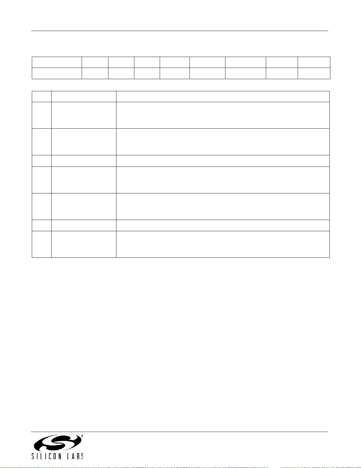
AN332
Table 10. Status Response for the FM/RDS Receiver
Bit D7 D6 D5 D4 D3 D2 D1 D0
STATUS
Bit Name Function
7CTS
6ERR
5:4 Reserved Values may vary.
3RSQINT
2 RDSINT
1 Reserved Values may vary.
0STCINT
CTS ERR X X RSQINT RDSINT X STCINT
Clear to Send.
0 = Wait before sending next command.
1 = Clear to send next command.
Error.
0=No error
1=Error
Received Signal Quality Interrupt.
0 = Received Signal Quality measurement has not been triggered.
1 = Received Signal Quality measurement has been triggered.
Radio Data System (RDS) Interrupt (Si4705/21/31/35/37/39/85 Only).
0 = Radio data system interrupt has not been triggered.
1 = Radio data system interrupt has been triggered.
Seek/Tune Complete Interrupt.
0 = Tune complete has not been triggered.
1 = Tune complete has been triggered.
Rev. 0.8 63
Page 64
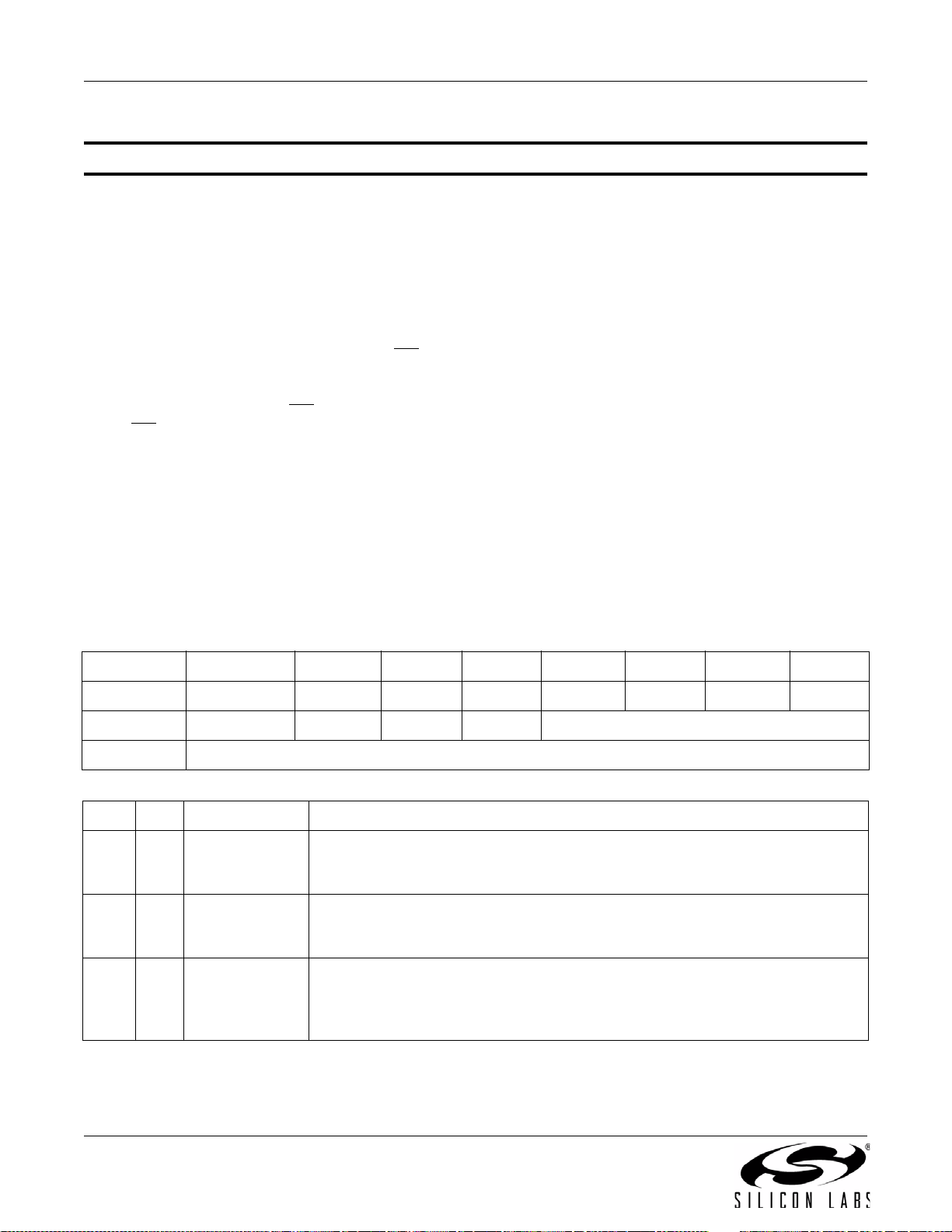
AN332
5.2.1. FM/RDS Receiver Commands
Command 0x01. POWER_UP
Initiates the boot process to move the device from powerdown to powerup mode. The boot can occur from internal
device memory or a system controller downloaded patch. To confirm that the patch is compatible with the internal
device library revision, the library revision should be confirmed by issuing the POWER_UP command with
FUNC = 15 (query library ID). The device returns the response, including the library revision, and then moves into
powerdown mode. The device can then be placed in powerup mode by issuing the POWER_UP command with
FUNC = 0 (FM Receive) and the patch may be applied (See Section "7.2. Powerup from a Component Patch" on
page 234).
The POWER_UP command configures the state of ROUT (pin 13, Si474x pin 15) and LOUT (pin 14, Si474x pin
16) for analog audio mode and GPO2/INT
Si4705/21/31/35/37/39/84/85-B20, the POWER_UP command also configures the state of GPO3/DCLK (pin 17,
Si474x pin 19), DFS (pin 16, Si474x pin 18), and DOUT (pin 15, Si474x pin 17) for digital audio mode. The
command configures GPO2/INT
GPO2/INT
bit is duplicated in the GPO_IEN property. The command is complete when the CTS bit (and optional interrupt) is
set.
Note: To change function (e.g. FM RX to AM RX or FM RX to FM TX), issue POWER_DOWN command to stop current func-
is driven high during normal operation and low for a minimum of 1 µs during the interrupt. The CTSIEN
tion; then, issue POWER_UP to start new function.
interrupts (GPO2OEN) and CTS interrupts (CTSIEN). If both are enabled,
(pin 18, Si474x pin 20) for interrupt operation. For the
Available in: All
Command Arguments: Two
Response Bytes: None (FUNC = 0), Seven (FUNC = 15)
Command
Bit D7 D6D5D4D3D2D1D0
CMD
ARG1 CTSIEN GPO2OEN PATCH XOSCEN FUNC[3:0]
ARG2 OPMODE[7:0]
ARG Bit Name Function
17 CTSIEN
1 6 GPO2OEN
15 PATCH
00000001
CTS Interrupt Enable.
0 = CTS interrupt disabled.
1 = CTS interrupt enabled.
GPO2 Output Enable.
0 = GPO2 output disabled.
1 = GPO2 output enabled.
Patch Enable.
0 = Boot normally.
1 = Copy NVM to RAM, but do not boot. After CTS has been set, RAM may be
patched.
64 Rev. 0.8
Page 65
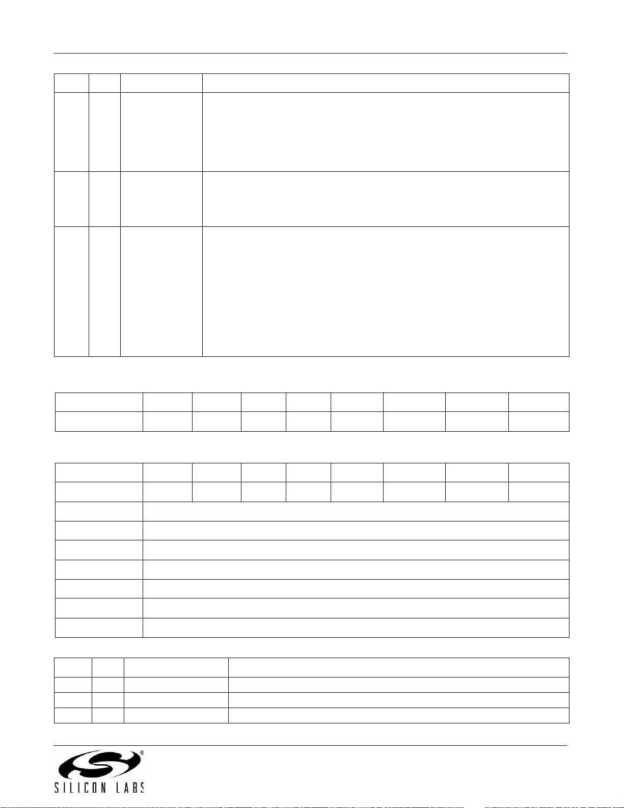
ARG Bit Name Function
Crystal Oscillator Enable.
Note: Set to 0 for Si4740/41/42/43/44/45/49
1 4 XOSCEN
1 3:0 FUNC[3:0]
2 7:0 OPMODE[7:0]
0 = Use external RCLK (crystal oscillator disabled).
1 = Use crystal oscillator (RCLK and GPO3/DCLK with external 32.768 kHz crys-
tal and OPMODE=00000101).
See Si47xx Data Sheet Application Schematic for external BOM details.
Function.
0=FM Receive.
1–14 = Reserved.
15 = Query Library ID.
Application Setting.
00000000 = RDS output only (no audio outputs) Si4749 only
00000101 = Analog audio outputs (LOUT/ROUT).
00001011 = Digital audio output (DCLK, LOUT/DFS, ROUT/DIO)
10110000 = Digital audio outputs (DCLK, DFS, DIO)
(Si4705/21/31/35/37/39/41/43/45/84/85 FMRX component 2.0 or
later with XOSCEN = 0).
10110101 = Analog and digital audio outputs (LOUT/ROUT and DCLK, DFS,
DIO) (Si4705/21/31/35/37/39/41/43/45/84/85 FMRX component 2.0
or later with XOSCEN = 0).
AN332
Response (FUNC = 0, FM Receive)
Bit D7 D6 D5 D4 D3 D2 D1 D0
STATUS
Response (FUNC = 15, Query Library ID)
Bit D7 D6 D5 D4 D3 D2 D1 D0
STATUS
RESP1 PN[7:0]
RESP2 FWMAJOR[7:0]
RESP3 FWMINOR[7:0]
RESP4 RESERVED[7:0]
RESP5 RESERVED[7:0]
RESP6 CHIPREV[7:0]
RESP7 LIBRARYID[7:0]
RESP Bit Name Function
1 7:0 PN[7:0] Final 2 digits of part number (HEX).
2 7:0 FWMAJOR[7:0] Firmware Major Revision (ASCII).
3 7:0 FWMINOR[7:0] Firmware Minor Revision (ASCII).
CTS ERR X X RSQINT RDSINT X STCINT
CTS ERR X X RSQINT RDSINT X STCINT
Rev. 0.8 65
Page 66
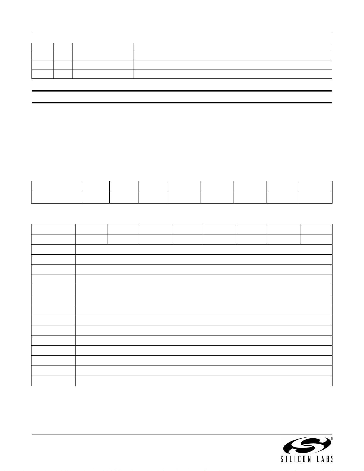
AN332
4 7:0 RESERVED[7:0] Reserved, various values.
5 7:0 RESERVED[7:0] Reserved, various values.
6 7:0 CHIPREV[7:0] Chip Revision (ASCII).
7 7:0 LIBRARYID[7:0] Library Revision (HEX).
Command 0x10. GET_REV
Returns the part number, chip revision, firmware revision, patch revision and component revision numbers. The
command is complete when the CTS bit (and optional interrupt) is set. This command may only be sent when in
powerup mode.
Available in: All
Command arguments: None
Response bytes: Fifteen (Si4705/06 only), Eight (Si4704/2x/3x/4x)
Command
Bit D7D6D5D4D3D2D1D0
CMD
Response
Bit D7D6D5D4D3D2D1D0
STATUS
RESP1 PN[7:0]
RESP2 FWMAJOR[7:0]
RESP3 FWMINOR[7:0]
RESP4 PATCH
RESP5 PAT CH
RESP6 CMPMAJOR[7:0]
RESP7 CMPMINOR[7:0]
RESP8 CHIPREV[7:0]
RESP10 Reserved
RESP11 Reserved
RESP12 Reserved
RESP13 Reserved
RESP14 Reserved
000 1 0 0 0 0
CTS ERR X X RSQINT RDSINT X STCINT
[7:0]
H
[7:0]
L
RESP15 CID[7:0] (Si4705 only)
66 Rev. 0.8
Page 67

AN332
RESP Bit Name Function
1 7:0 PN[7:0] Final 2 digits of Part Number (HEX).
2 7:0 FWMAJOR[7:0] Firmware Major Revision (ASCII).
3 7:0 FWMINOR[7:0] Firmware Minor Revision (ASCII).
47:0 PATCH
57:0 PATCH
6 7:0 CMPMAJOR[7:0] Component Major Revision (ASCII).
7 7:0 CMPMINOR[7:0] Component Minor Revision (ASCII).
8 7:0 CHIPREV[7:0] Chip Revision (ASCII).
15 7:0 CID[7:0] CID (Si4705/06 only).
Command 0x11. POWER_DOWN
Moves the device from powerup to powerdown mode. The CTS bit (and optional interrupt) is set when it is safe to
send the next command. This command may only be sent when in powerup mode. Note that only the POWER_UP
command is accepted in powerdown mode.
when in powerdown mode, the device does not respond. The device will only respond when a POWER_UP
command is written. GPO pins are powered down and not active during this state. For optimal power down
current, GPO2 must be either internally driven low through GPIO_CTL command or externally driven low.
[7:0] Patch ID High Byte (HEX).
H
[7:0] Patch ID Low Byte (HEX).
L
If the system controller writes a command o ther t han POWER_UP
Note: In FMRX component 1.0, a reset is required when the system controller writes a command other than POWER_UP
when in powerdown mode.
Note: The following describes the state of all the pins when in powerdown mode:
GPIO1, GPIO2, and GPIO3 = 0
ROUT, LOUT, DOUT, DFS = HiZ
Available in: All
Command arguments: None
Response bytes: None
Command
Bit D7D6D5D4D3D2D1D0
CMD
00010001
Response
Bit D7 D6 D5 D4 D3 D2 D1 D0
STATUS
CTS ERR X X RSQINT RDSINT X STCINT
Rev. 0.8 67
Page 68

AN332
Command 0x12. SET_PROPERTY
Sets a property shown in Table 9, “FM/RDS Receiver Property Summary,” on page 56. The CTS bit (and optional
interrupt) is set when it is safe to send the next command. This command may only be sent when in powerup
mode. See Figure 30, “CTS and SET_PROPERTY Command Complete tCOMP Timing Model,” on page 244 and
Table 49, “Command Timing Parameters for the FM Receiver,” on page 246.
Available in: All
Command Arguments: Five
Response bytes: None
Command
Bit D7D6D5D4D3D2D1D0
CMD
00010010
ARG1 00000000
ARG2 PROP
ARG3 PROP
ARG4 PROPD
ARG5 PROPD
[7:0]
H
[7:0]
L
H
L
[7:0]
[7:0]
ARG Bit Name Function
1 7:0 Reserved Always write to 0.
Property High Byte.
27:0PROP
37:0PROP
47:0PROPD
57:0PROPD
H
L
H
L
[7:0]
This byte in combination with PROPL is used to specify the property to modify.
Property Low Byte.
[7:0]
This byte in combination with PROPH is used to specify the property to modify.
Property Value High Byte.
[7:0]
This byte in combination with PROPDL is used to set the property value.
Property Value Low Byte.
[7:0]
This byte in combination with PROPDH is used to set the property value.
68 Rev. 0.8
Page 69
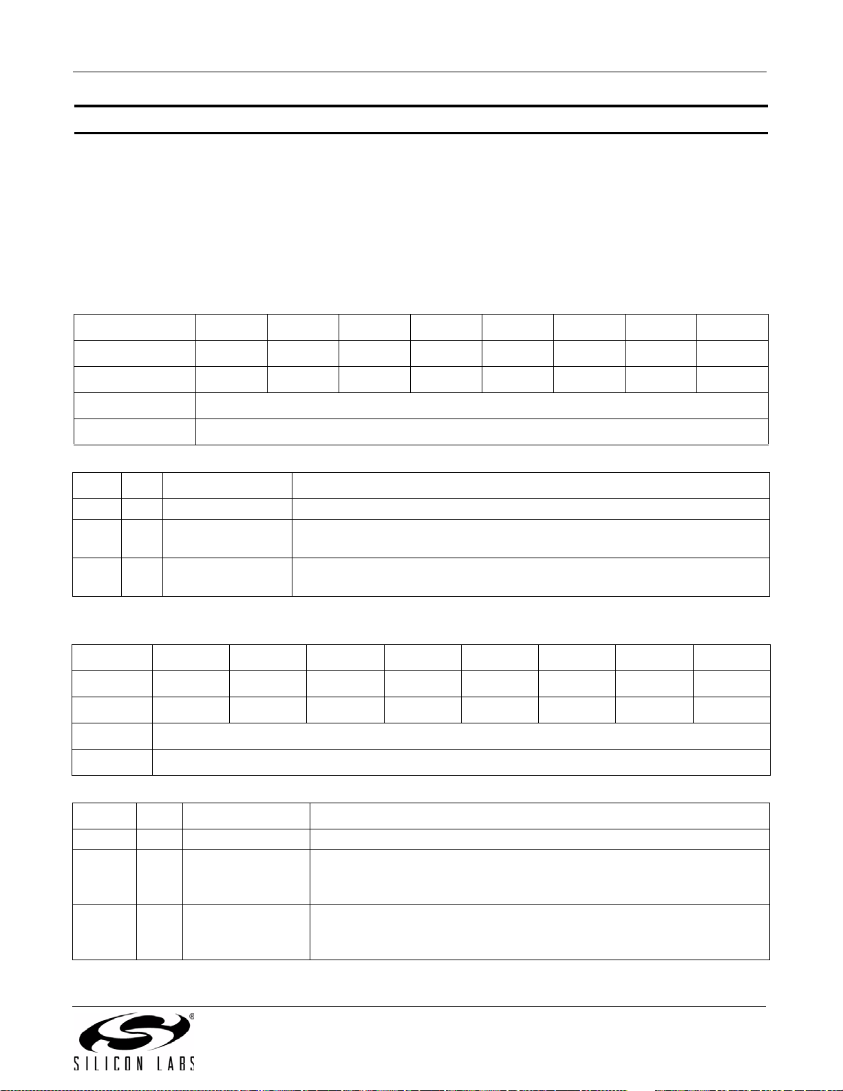
AN332
Command 0x13. GET_PROPERTY
Gets a property as shown in Table 9, “FM/RDS Receiver Property Summary,” on page 56. The CTS bit (and
optional interrupt) is set when it is safe to send the next command. This command may only be sent when in
powerup mode.
Available in: All
Command arguments: Three
Response bytes: Three
Command
Bit D7D6D5D4D3D2D1D0
CMD
00010011
ARG1 00000000
ARG2 PROP
ARG3 PROP
[7:0]
H
[7:0]
L
ARG Bit Name Function
1 7:0 Reserved Always write to 0.
27:0 PROP
37:0 PROP
H
L
[7:0]
[7:0]
Property High Byte.
This byte in combination with PROPL is used to specify the property to get.
Property Low Byte.
This byte in combination with PROPH is used to specify the property to get.
Response
BitD7D6D5D4D3D2D1D0
STATUS
CTS ERR X X RSQINT RDSINT X STCINT
RESP1 00000000
RESP2 PROPD
RESP3 PROPD
[7:0]
H
[7:0]
L
RESP Bit Name Function
1 7:0 Reserved Always returns 0.
Property Value High Byte.
27:0PROPD
H
[7:0]
This byte in combination with PROPDL represents the requested property
value.
Property Value High Byte.
37:0PROPD
[7:0]
L
This byte in combination with PROPDH represents the requested property
value.
Rev. 0.8 69
Page 70
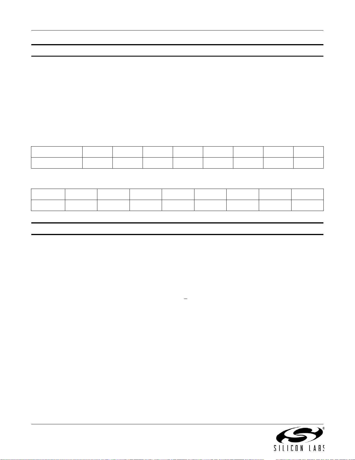
AN332
Command 0x14. GET_INT_STATUS
Updates bits 6:0 of the status byte. This command should be called after any command that sets the STCINT,
RDSINT, or RSQINT bits. When polling this command should be periodically called to monitor the STATUS byte,
and when using interrupts, this command should be called after the interrupt is set to update the STATUS byte. The
CTS bit (and optional interrupt) is set when it is safe to send the next command. This command may only be set
when in powerup mode.
Available in: All
Command arguments: None
Response bytes: None
Command
Bit D7D6D5D4D3D2D1D0
CMD
Response
BitD7D6D5D4D3D2D1D0
STATUS
Command 0x20. FM_TUNE_FREQ
Sets the FM Receive to tune a frequency between 64 and 108 MHz in 10 kHz units. The CTS bit (and optional
interrupt) is set when it is safe to send the next command. The ERR bit (and optional interrupt) is set if an invalid
argument is sent. Note that only a single interrupt occurs if both the CTS and ERR bits are set. The optional STC
interrupt is set when the command completes. The STCINT bit is set only after the GET_INT_STATUS command is
called. This command may only be sent when in powerup mode. The command clears the STC bit if it is already
set. See Figure 29, “CTS and STC Timing Model,” on page 244 and Table 49, “Command Timing Parameters for
the FM Receiver,” on page 246.
FM: LO frequency is 128 kHz above RF for RF frequencies <
90 MHz. For example, LO frequency is 80.128 MHz when tuning to 80.00 MHz.
Note: For FMRX components 2.0 or earlier, tuning range is 76–108 MHz.
Note: Fast bit is supported in FMRX components 4.0 or later.
Note: Freeze bit is supported in FMRX components 4.0 or later.
CTS ERR X X RSQINT RDSINT X STCINT
00010100
90 MHz and 128 kHz below RF for RF frequencies >
Available in: All
Command arguments: Four
Response bytes: None
70 Rev. 0.8
Page 71
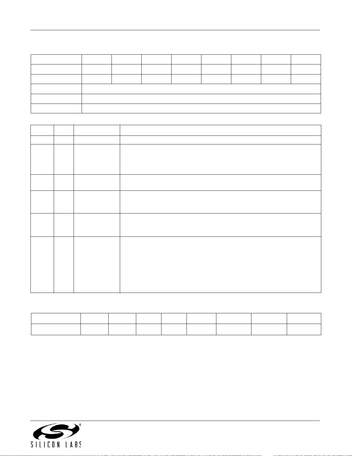
Command
Bit D7D6D5D4D3D2D1D0
CMD
00100000
ARG1 000000FREEZEFAST
ARG2 FREQ
ARG3 FREQ
[7:0]
H
[7:0]
L
ARG4 ANTCAP[7:0]
ARG Bit Name Function
1 7:1 Reserved Always write to 0.
Freeze Metrics During Alternate Frequency Jump.
11 FREEZE
If set will cause the blend, hicut, and softmute to transition as a function of the
associated attack/release parameters rather than instantaneously when tuning
to alternate station.
1 0 FAST
FAST Tuning.
If set, executes fast and invalidated tune. The tune status will not be accurate.
Tune Frequency High Byte.
27:0FREQ
H
[7:0]
This byte in combination with FREQL selects the tune frequency in 10 kHz. In
FM mode the valid range is from 6400 to 10800 (64–108 MHz).
Tune Frequency Low Byte.
37:0FREQ
[7:0]
L
This byte in combination with FREQH selects the tune frequency in 10 kHz. In
FM mode the valid range is from 6400 to 10800 (64–108 MHz).
Antenna Tuning Capacitor (valid only when using TXO/LPI pin as the
antenna input).
This selects the value of the antenna tuning capacitor manually, or automati-
4 7:0 ANTCAP[7:0]
cally if set to zero. The valid range is 0 to 191. Automatic capacitor tuning is
recommended.
Note: When tuned manually, the varactor is offset by four codes. For example, if the
varactor is set to a value of 5 manually, when read back the value will be 1. The
four codes (1pf) delta accounts for the capacitance at the chip.
AN332
Response
Bit D7 D6 D5 D4 D3 D2 D1 D0
STATUS
CTS ERR X X RSQINT RDSINT X STCINT
Rev. 0.8 71
Page 72
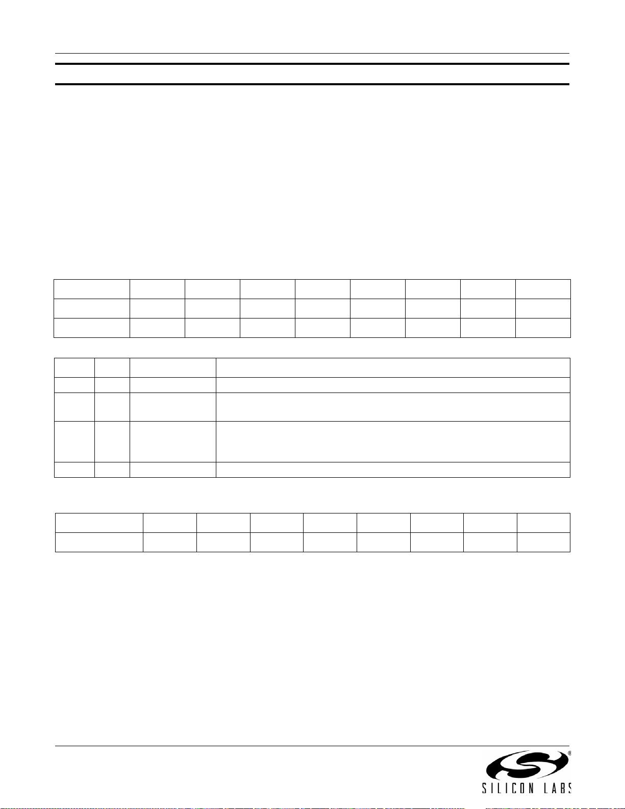
AN332
Command 0x21. FM_SEEK_START
Begins searching for a valid frequency. Clears any pending STCINT or RSQINT interrupt status. The CTS bit (and
optional interrupt) is set when it is safe to send the next command. RSQINT status is only cleared by the RSQ
status command when the INTACK bit is set. The ERR bit (and optional interrupt) is set if an invalid argument is
sent. Note that only a single interrupt occurs if both the CTS and ERR bits are set. The optional STC interrupt is set
when the command completes. The STCINT bit is set only after the GET_INT_STATUS command is called. This
command may only be sent when in powerup mode. The command clears the STCINT bit if it is already set. See
Figure 29, “CTS and STC Timing Model,” on page 244 and Table 49, “Command Timing Parameters for the FM
Receiver,” on page 246.
Available in: All
Command arguments: One
Response bytes: None
Command
Bit D7D6D5D4D3D2D1D0
CMD
ARG1 0 0 0 0 SEEKUP WRAP 0 0
ARG Bit Name Function
1 7:4 Reserved Always write to 0.
1 3 SEEKUP
12 WRAP
1 1:0 Reserved Always write to 0.
Response
Bit D7D6D5D4D3D2D1D0
STATUS
00100001
Seek Up/Down.
Determines the direction of the search, either UP = 1, or DOWN = 0.
Wrap/Halt.
Determines whether the seek should Wrap = 1, or Halt = 0 when it hits the
band limit.
CTS ERR X X RSQINT RDSINT X STCINT
72 Rev. 0.8
Page 73
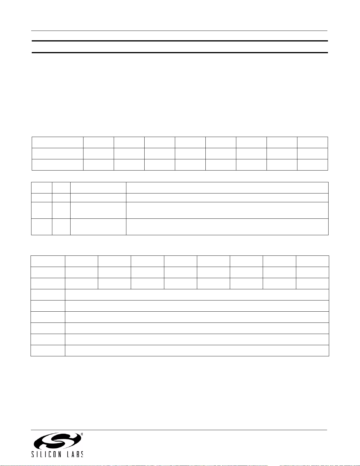
AN332
Command 0x22. FM_TUNE_STATUS
Returns the status of FM_TUNE_FREQ or FM_SEEK_START commands. The command returns the current
frequency, RSSI, SNR, multipath, and the antenna tuning capacitance value (0-191). The command clears the
STCINT interrupt bit when INTACK bit of ARG1 is set. The CTS bit (and optional interrupt) is set when it is safe to
send the next command. This command may only be sent when in powerup mode.
Available in: All
Command arguments: One
Response bytes: Seven
Command
Bit D7D6D5D4D3D2D1D0
CMD
ARG1 000000CANCELINTACK
ARG Bit Name Function
1 7:2 Reserved Always write to 0.
11 CANCEL
10 INTACK
Response
BitD7D6D5D4D3D2D1D0
STATUS
RESP1 BLTFXXXXXAFCRLVALID
RESP2 READFREQ
RESP3 READFREQ
RESP4 RSSI[7:0]
CTS ERR X X RSQINT RDSINT X STCINT
00100010
Cancel seek.
If set, aborts a seek currently in progress.
Seek/Tune Interrupt Clear.
If set, clears the seek/tune complete interrupt status indicator.
[7:0]
H
[7:0]
L
RESP5 SNR[7:0]
RESP6 MULT[7:0]
RESP7 READANTCAP[7:0] (Si4704/05/06/2x only)
Rev. 0.8 73
Page 74

AN332
RESP Bit Name Function
Band Limit.
17 BLTF
1 6:2 Reserved Always returns 0.
1 1 AFCRL
10 VALID
2 7:0 READFREQ
3 7:0 READFREQ
H
L
Reports if a seek hit the band limit (WRAP = 0 in FM_START_SEEK) or
wrapped to the original frequency (WRAP = 1).
AFC Rail Indicator.
Set if the AFC rails.
Valid Channel.
Set if the channel is currently valid as determined by the seek/tune properties (0x1403, 0x1404, 0x1108) and would have been found during a Seek.
Read Frequency High Byte.
[7:0]
This byte in combination with READFREQL returns frequency being tuned
(10 kHz).
Read Frequency Low Byte.
[7:0]
This byte in combination with READFREQH returns frequency being tuned
(10 kHz).
4 7:0 RSSI[7:0]
5 7:0 SNR[7:0]
6 7:0 MULT[7:0]
7 7:0 READANTCAP [7:0]
Received Signal Strength Indicator.
This byte contains the receive signal strength when tune is complete (dBµV).
SNR.
This byte contains the SNR metric when tune is complete (dB).
Multipath.
This byte contains the multipath metric when tune is complete. Multipath indicator is available only for Si474x, Si4706-C30 and later and
Si4704/05/30/31/34/35/84/85 -D50 and later.
Read Antenna Tuning Capacitor (Si4704/05/06/2x only).
This byte contains the current antenna tuning capacitor value.
74 Rev. 0.8
Page 75
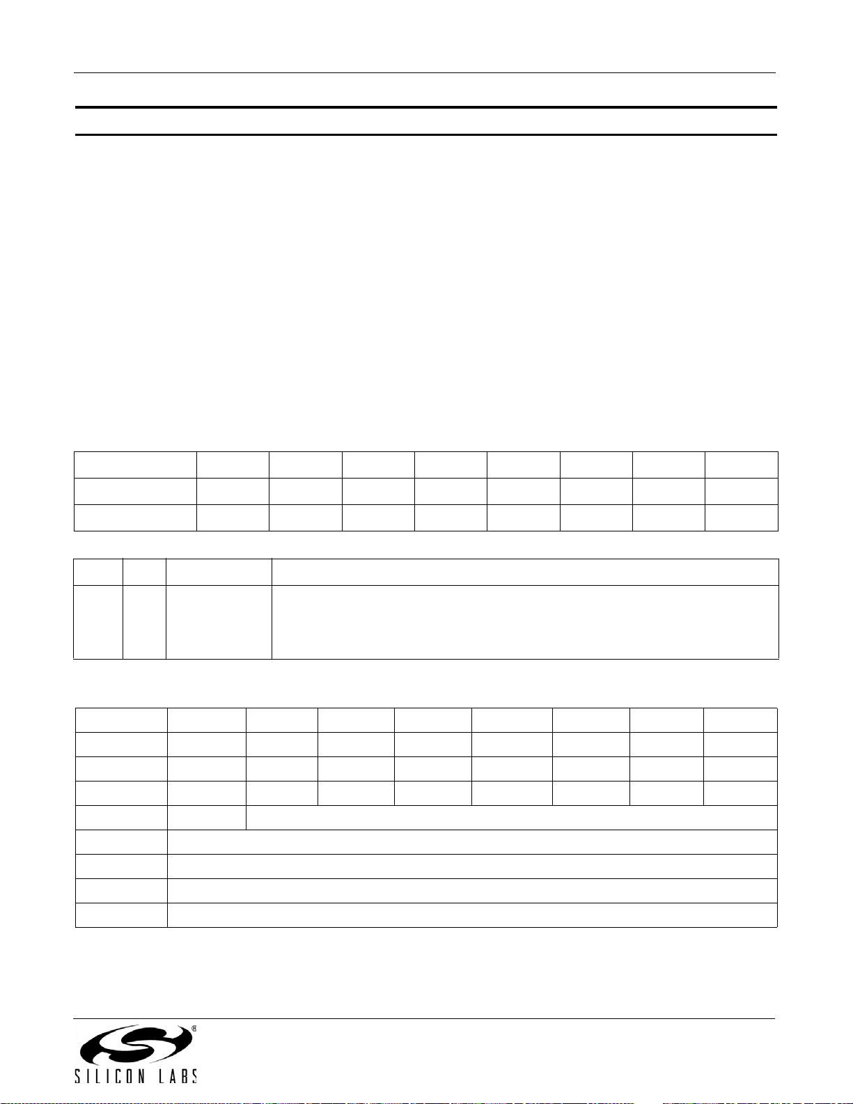
AN332
Command 0x23. FM_RSQ_STATUS
Returns status information about the received signal quality. The commands returns the RSSI, SNR, frequency
offset, and stereo blend percentage. It also indicates valid channel (VALID), soft mute engagement (SMUTE), and
AFC rail status (AFCRL). This command can be used to check if the received signal is above the RSSI high
threshold as reported by RSSIHINT, or below the RSSI low threshold as reported by RSSILINT. It can also be used
to check if the signal is above the SNR high threshold as reported by SNRHINT, or below the SNR low threshold as
reported by SNRLINT. For the Si4706/4x, it can be used to check if the detected multipath is above the multipath
high threshold as reported by MULTHINT, or below the multipath low threshold as reported by MULTLINT. If the
PILOT indicator is set, it can also check whether the blend has crossed a threshold as indicated by BLENDINT.
The command clears the RSQINT, BLENDINT, SNRHINT, SNRLINT, RSSIHINT, RSSILINT, MULTHINT, and
MULTLINT interrupt bits when INTACK bit of ARG1 is set. The CTS bit (and optional interrupt) is set when it is safe
to send the next command. This command may only be sent when in powerup mode.
Available in: All
Command arguments: One
Response bytes: Seven
Command
Bit D7D6D5D4D3D2D1D0
CMD
ARG1 0000000INTACK
ARG Bit Name Function
10 INTACK
Response
Bit D7 D6 D5 D4 D3 D2 D1 D0
STATUS
RESP1 BLENDINT X MULTHINT MULTLINT SNRHINT SNRLINT RSSIHINT RSSIILINT
RESP2 X X X X SMUTE X AFCRL VALID
RESP3 PILOT STBLEND[6:0]
RESP4 RSSI[7:0]
RESP5 SNR[7:0]
RESP6 MULT[7:0]
00100011
Interrupt Acknowledge.
0 = Interrupt status preserved.
1 = Clears RSQINT, BLENDINT, SNRHINT, SNRLINT, RSSIHINT, RSSILINT,
MULTHINT, MULTLINT.
CTS ERR X X RSQINT RDSINT X STCINT
RESP7 FREQOFF[7:0]
Rev. 0.8 75
Page 76
AN332
RESP Bit Name Function
Blend Detect Interrupt.
1 7 BLENDINT
15MULTHINT
14MULTLINT
1 3 SNRHINT
12 SNRLINT
1 1 RSSIHINT
1 0 RSSILINT
23 SMUTE
21 AFCRL
20 VALID
37 PILOT
3 6:0 STBLEND[6:0]
4 7:0 RSSI[7:0]
5 7:0 SNR[7:0]
6 7:0 MULT[7:0]
7 7:0 FREQOFF[7:0]
0 = Blend is within the Blend threshold settings.
1 = Blend goes above or below the Blend threshold settings.
Multipath Detect High (Si474x, Si4706-C30 and later and
Si4704/05/30/31/34/35/84/85-D50 and later only).
0 = Detected multipath value has not exceeded above the Multipath high threshold.
1 = Detected multipath value has exceeded above the Multipath high threshold.
Multipath Detect Low (Si474x, Si4706-C30 and later and
Si4704/05/30/31/34/35/84/85-D50 and later only).
0 = Detected multipath value has not fallen below the Multipath low threshold.
1 = Detected multipath value has fallen below the Multipath low threshold.
SNR Detect High.
0 = Received SNR has not exceeded above SNR high threshold.
1 = Received SNR has exceeded above SNR high threshold.
SNR Detect Low.
0 = Received SNR has not fallen below SNR low threshold.
1 = Received SNR has fallen below SNR low threshold.
RSSI Detect High.
0 = RSSI has not exceeded above RSSI high threshold.
1 = RSSI has exceeded above RSSI high threshold.
RSSI Detect Low.
0 = RSSI has not fallen below RSSI low threshold.
1 = RSSI has fallen below RSSI low threshold.
Soft Mute Indicator.
Indicates soft mute is engaged.
AFC Rail Indicator.
Set if the AFC rails.
Valid Channel.
Set if the channel is currently valid and would have been found during a Seek.
Pilot Indicator.
Indicates stereo pilot presence.
Stereo Blend Indicator.
Indicates amount of stereo blend in% (100 = full stereo, 0 = full mono).
Received Signal Strength Indicator.
Contains the current receive signal strength (0–127 dBµV).
SNR.
Contains the current SNR metric (0–127 dB).
Multipath (Si474x, Si4706-C30 and later and Si4704/05/30/31/34/35/84/85-D50
and later only).
Contains the current multipath metric. (0 = no multipath; 100 = full multipath)
Frequency Offset.
Signed frequency offset (kHz).
76 Rev. 0.8
Page 77
AN332
Command 0x24. FM_RDS_STATU S
Returns RDS information for current channel and reads an entry from the RDS FIFO. RDS information includes
synch status, FIFO status, group data (blocks A, B, C, and D), and block errors corrected. This command clears
the RDSINT interrupt bit when INTACK bit in ARG1 is set and, if MTFIFO is set, the entire RDS receive FIFO is
cleared (FIFO is always cleared during FM_TUNE_FREQ or FM_SEEK_START). The CTS bit (and optional
interrupt) is set when it is safe to send the next command. This command may only be sent when in power up
mode. The FIFO size is 25 groups for FMRX component 2.0 or later, and 14 for FMRX component 1.0.
Notes:
1. FM_RDS_STATUS is supported in FMRX component 2.0 or later.
2. MTFIFO is not supported in FMRX component 2.0.
Available in: Si4705/06, Si4721, Si474x, Si4731/35/37/39, Si4785
Command arguments: One
Response bytes: Twelve
Command
Bit D7 D6 D5 D4 D3 D2 D1 D0
CMD 0 0 1 0 0 1 0 0
ARG1 0 0 0 0 0 STATUSONLY MTFIFO INTACK
ARG Bit Name Function
Status Only.
Determines if data should be removed from the RDS FIFO.
0 = Data in BLOCKA, BLOCKB, BLOCKC, BLOCKD, and BLE contain the oldest
12STATUSONLY
data in the RDS FIFO.
1 = Data in BLOCKA will contain the last valid block A data received for the cur-
rent station. Data in BLOCKB will contain the last valid block B data received for
the current station. Data in BLE will describe the bit errors for the data in
BLOCKA and BLOCKB.
Empty FIFO
1 1 MTFIFO
0 = If FIFO not empty, read and remove oldest FIFO entry.
1 = Clear RDS Receive FIFO.
Interrupt Acknowledge
10 INTACK
0 = RDSINT status preserved.
1 = Clears RDSINT.
Response
Bit D7 D6 D5 D4 D3 D2 D1 D0
STATUS CTS ERR X X RSQINT RDSINT X STCINT
RESP1 X X RDSNEWBLOCKB RDSNEWBLOCKA X RDSSYNCFOUND RDSSYNCLOST RDSRECV
RESP2 X X X X X GRPLOST X RDSSYNC
Rev. 0.8 77
Page 78
AN332
Bit D7 D6 D5 D4 D3 D2 D1 D0
RESP3 RDSFIFOUSED[7:0]
RESP4 BLOCKA[15:8]
RESP5 BLOCKA[7:0]
RESP6 BLOCKB[15:8]
RESP7 BLOCKB[7:0]
RESP8 BLOCKC[15:8]
RESP9 BLOCKC[7:0]
RESP10 BLOCKD[15:8]
RESP11 BLOCKD[7:0]
RESP12 BLEA[1:0] BLEB[1:0] BLEC[1:0] BLED[1:0]
RESP Bit Name Function
1 5 RDSNEWBLOCKB
1 4 RDSNEWBLOCKA
1 2 RDSSYNCFOUND
1 1 RDSSYNCLOST
1 0 RDSRECV
22 GRPLOST
2 0 RDSSYNC
3 7:0 RDSFIFOUSED
4 7:0 BLOCKA[15:8]
5 7:0 BLOCKA[7:0]
6 7:0 BLOCKB[15:8]
7 7:0 BLOCKB[7:0]
8 7:0 BLOCKC[15:8]
9 7:0 BLOCKC[7:0]
RDS New Block B.
1 = Valid Block B data has been received.
RDS New Block A.
1 = Valid Block A data has been received.
RDS Sync Found.
1 = Found RDS synchronization.
RDS Sync Lost.
1 = Lost RDS synchronization.
RDS Received.
1 = FIFO filled to minimum number of groups set by RDSFIFOCNT.
Group Lost.
1 = One or more RDS groups discarded due to FIFO overrun.
RDS Sync.
1 = RDS currently synchronized.
RDS FIFO Used.
Number of groups remaining in the RDS FIFO (0 if empty). If non-zero,
BLOCKA-BLOCKD contain the oldest FIFO entry and RDSFIFOUSED decrements by one on the next call to RDS_FIFO_STATUS (assuming no RDS
data received in the interim).
RDS Block A.
Block A group data from oldest FIFO entry if STATUSONLY is 0. Last valid
Block A data if STATUSONLY is 1 (Si4749, Si4706-C30 and later and
Si4705/31/35/85-D50 and later only).
RDS Block B.
Block B group data from oldest FIFO entry if STATUSONLY is 0. Last valid
Block B data if STATUSONLY is 1 (Si4749, Si4706-C30 and later and
Si4705/31/35/85-D50 and later only).
RDS Block C.
Block C group data from oldest FIFO entry.
78 Rev. 0.8
Page 79

RESP Bit Name Function
AN332
10 7:0 BLOCKD[15:8]
11 7:0 BLOCKD[7:0]
12 7:6 BLEA[1:0]
12 5:4 BLEB[1:0]
12 3:2 BLEC[1:0]
12 1:0 BLED[1:0]
RDS Block D.
Block D group data from oldest FIFO entry.
RDS Block A Corrected Errors.
0 = No errors.
1 = 1–2 bit errors detected and corrected.
2 = 3–5 bit errors detected and corrected.
3 = Uncorrectable.
RDS Block B Corrected Errors.
0 = No errors.
1 = 1–2 bit errors detected and corrected.
2 = 3–5 bit errors detected and corrected.
3 = Uncorrectable.
RDS Block C Corrected Errors.
0 = No errors.
1 = 1–2 bit errors detected and corrected.
2 = 3–5 bit errors detected and corrected.
3 = Uncorrectable.
RDS Block D Corrected Errors.
0 = No errors.
1 = 1–2 bit errors detected and corrected.
2 = 3–5 bit errors detected and corrected.
3 = Uncorrectable.
Rev. 0.8 79
Page 80
AN332
Command 0x27. FM_AGC_STAT US
Returns the AGC setting of the device. The command returns whether the AGC is enabled or disabled and it
returns the LNA Gain index. This command may only be sent when in powerup mode.
Available in: All
Command arguments: None
Response bytes: Two
Command
BitD7D6D5D4D3D2D1D0
CMD
00100111
Response
BitD7D6D5D4D3D2D1D0
STATUS
RESP1
RESP2
CTS ERR X X RSQINT RDSINT X STCINT
XXXXXXX
READ_RF
AGCDIS
X X X READ_LNA_GAIN_INDEX[4:0]
RESP Bit Name Function
This bit indicates whether the RF AGC is disabled or not
1 0 READ_RFAGCDIS
2 4:0 READ_LNA_GAIN_INDEX
0 = RF AGC is enabled
1 = RF AGC is disabled
These bits returns the value of the LNA GAIN index
0 = Minimum attenuation (max gain)
1 – 25 = Intermediate attenuation
26 = Maximum attenuation (min gain)
Note: The max index is subject to change
80 Rev. 0.8
Page 81
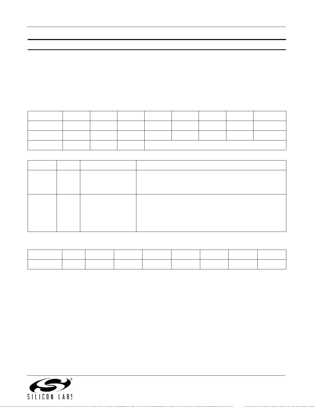
AN332
Command 0x28. FM_AGC_OVERRIDE
Overrides AGC setting by disabling the AGC and forcing the LNA to have a certain gain that ranges between 0
(minimum attenuation) and 26 (maximum attenuation). This command may only be sent when in powerup mode.
Available in: All
Command arguments: Two
Response bytes: None
Command
Bit D7D6D5D4D3D2D1 D0
CMD
ARG1 XXXXXXXRFAGCDIS
ARG2 X X X LNA_GAIN_INDEX[4:0]
ARG Bit Name Function
10 RFAGCDIS
2 4:0 LNA_GAIN_INDEX
Response
BitD7D6D5D4D3D2D1D0
STATUS
0010100 0
This bit selects whether the RF AGC is disabled or not
0 = RF AGC is enabled
1 = RF AGC is disabled
These bits set the value of the LNA GAIN index
0 = Minimum attenuation (max gain)
1 – 25 = Intermediate attenuation
26 = Maximum attenuation (min gain)
Note: the max index is subject to change
CTS ERR X X RSQINT RDSINT X STCINT
Rev. 0.8 81
Page 82
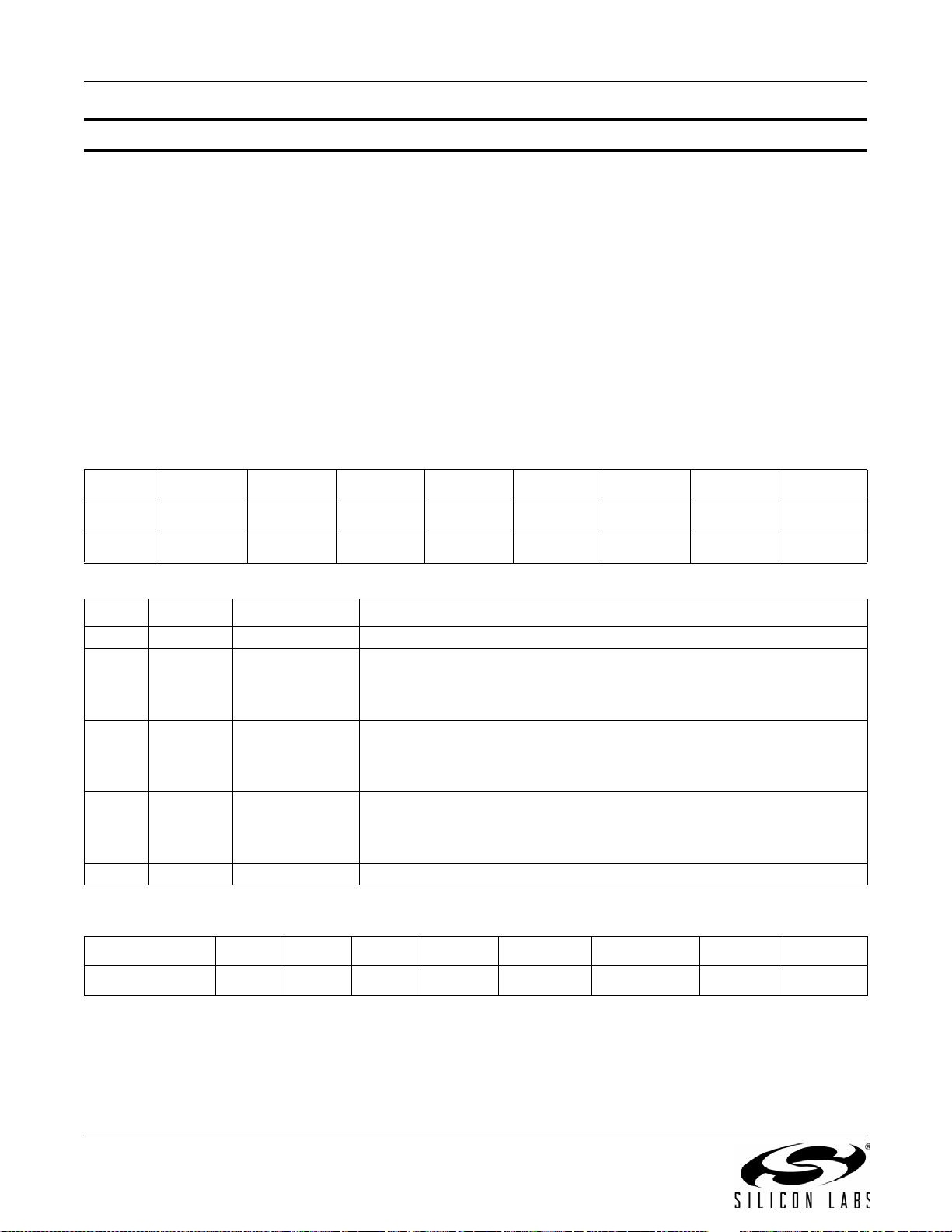
AN332
Command 0x80. GPIO_CTL
Enables output for GPO1, 2, and 3. GPO1, 2, and 3 can be configured for output (Hi-Z or active drive) by setting
the GPO1OEN, GPO2OEN, and GPO3OEN bit. The state (high or low) of GPO1, 2, and 3 is set with the
GPIO_SET command. To avoid excessive current consumption due to oscillation, GPO pins should not be left in a
high impedance state. The CTS bit (and optional interrupt) is set when it is safe to send the next command. This
command may only be sent when in powerup mode. The default is all GPO pins set for high impedance.
Notes:
1. GPIO_CTL is fully supported in FMRX component 2.0 or later. Only bit GPO3OEN is supported in FMRX component 1.0.
2. The use of GPO2 as an interrupt pin and/or the use of GPO3 as DCLK digital clock input will override this GPIO_CTL
function for GPO2 and/or GPO3 respectively.
Available in: All except Si4710-A10
Command arguments: One
Response bytes: None
Command
BitD7D6D5D4D3D2D1D0
CMD
ARG1 0 0 0 0 GPO3OEN GPO2OEN GPO1OEN 0
ARG Bit Name Function
1 7:4 Reserved Always write 0.
1 3 GPO3OEN
1 2 GPO2OEN
1 1 GPO1OEN
1 0 Reserved Always write 0.
Response
Bit D7D6D5 D4 D3 D2 D1 D0
10000000
GPO3 Output Enable.
0 = Output Disabled (Hi-Z) (default).
1 = Output Enabled.
GPO2 Output Enable.
0 = Output Disabled (Hi-Z) (default).
1 = Output Enabled.
GPO1 Output Enable.
0 = Output Disabled (Hi-Z) (default).
1 = Output Enabled.
STATUS
82 Rev. 0.8
CTS ERR X X X RDSINT ASQINT STCINT
Page 83
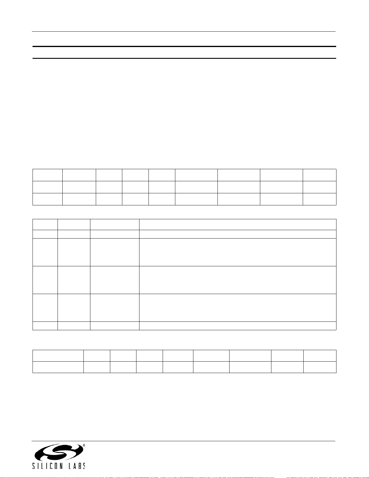
AN332
Command 0x81. GPIO_SET
Sets the output level (high or low) for GPO1, 2, and 3. GPO1, 2, and 3 can be configured for output by setting the
GPO1OEN, GPO2OEN, and GPO3OEN bit in the GPIO_CTL command. To avoid excessive current consumption
due to oscillation, GPO pins should not be left in a high impedance state. The CTS bit (and optional interrupt) is set
when it is safe to send the next command. This property may only be set or read when in powerup mode. The
default is all GPO pins set for high impedance.
Note: GPIO_SET is fully-supported in FMRX component 2.0 or later. Only bit GPO3LEVEL is supported in FMRX component
1.0.
Available in: All except Si4710-A10
Command arguments: One
Response bytes: None
Command
Bit D7 D6D5D4 D3 D2 D1 D0
CMD
ARG1 0 0 0 0 GPO3LEVEL GPO2LEVEL GPO1LEVEL 0
ARG Bit Name Function
1 7:4 Reserved Always write 0.
1 3 GPO3LEVEL
1 2 GPO2LEVEL
1 1 GPO1LEVEL
1 0 Reserved Always write 0.
Response
Bit D7D6D5 D4 D3 D2 D1 D0
10000001
GPO3 Output Level.
0 = Output low (default).
1 = Output high.
GPO2 Output Level.
0 = Output low (default).
1 = Output high.
GPO1 Output Level.
0 = Output low (default).
1 = Output high.
STATUS
CTS ERR X X X RDSINT ASQINT STCINT
Rev. 0.8 83
Page 84
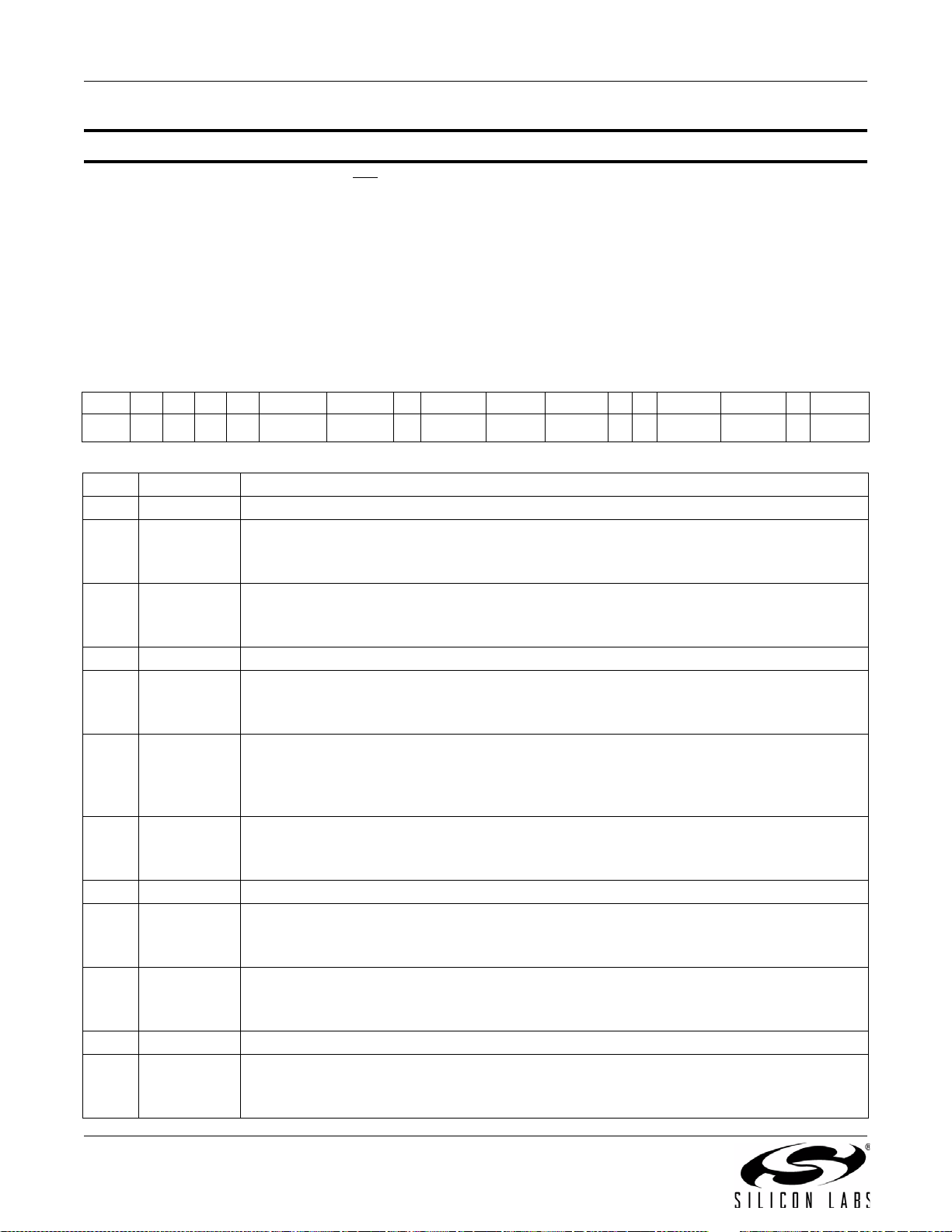
AN332
5.2.2. FM/RDS Receiver Properties
Property 0x0001. GPO_IEN
Configures the sources for the GPO2/INT interrupt pin. Valid sources are the lower 8 bits of the STATUS byte,
including CTS, ERR, RSQINT, RDSINT (Si4705/21/31/35/37/39/41/43/45/85 only), and STCINT bits. The
corresponding bit is set before the interrupt occurs. The CTS bit (and optional interrupt) is set when it is safe to
send the next command. The CTS interrupt enable (CTSIEN) can be set with this property and the POWER_UP
command. The state of the CTSIEN bit set during the POWER_UP command can be read by reading this property
and modified by writing this property. This property may only be set or read when in powerup mode.
Errata:RSQIEN is non-functional on FMRX component 2.0.
Available in: All
Default: 0x0000
Bit D15 D14 D13 D12 D11 D10 D9 D8 D7 D6 D5 D4 D3 D2 D1 D0
Name 0 0 0 0 RSQREP RDSREP 0 STCREP CTSIEN ERRIEN 0 0 RSQIEN RDSIEN 0 STCIEN
Bit Name Function
15:12 Reserved Always write to 0.
RSQ Interrupt Repeat.
11 RSQREP
10 RDSREP
9 Reserved Always write to 0.
8 STCREP
7CTSIEN
6ERRIEN
5:4 Reserved Always write to 0.
3RSQIEN
2RDSIEN
1 Reserved Always write to 0.
0STCIEN
0 = No interrupt generated when RSQINT is already set (default).
1 = Interrupt generated even if RSQINT is already set.
RDS Interrupt Repeat (Si4705/21/31/35/37/39/41/43/45/85-C40 Only).
0 = No interrupt generated when RDSINT is already set (default).
1 = Interrupt generated even if RDSINT is already set.
STC Interrupt Repeat.
0 = No interrupt generated when STCINT is already set (default).
1 = Interrupt generated even if STCINT is already set.
CTS Interrupt Enable. After PowerUp, this bit reflects the CTSIEN bit in ARG1 of PowerUp Command.
0 = No interrupt generated when CTS is set.
1 = Interrupt generated when CTS is set.
ERR Interrupt Enable.
0 = No interrupt generated when ERR is set (default).
1 = Interrupt generated when ERR is set.
RSQ Interrupt Enable.
0 = No interrupt generated when RSQINT is set (default).
1 = Interrupt generated when RSQINT is set.
RDS Interrupt Enable (Si4705/21/31/35/37/39/41/43/45/85-C40 Only).
0 = No interrupt generated when RDSINT is set (default).
1 = Interrupt generated when RDSINT is set.
Seek/Tune Complete Interrupt Enable.
0 = No interrupt generated when STCINT is set (default).
1 = Interrupt generated when STCINT is set.
84 Rev. 0.8
Page 85
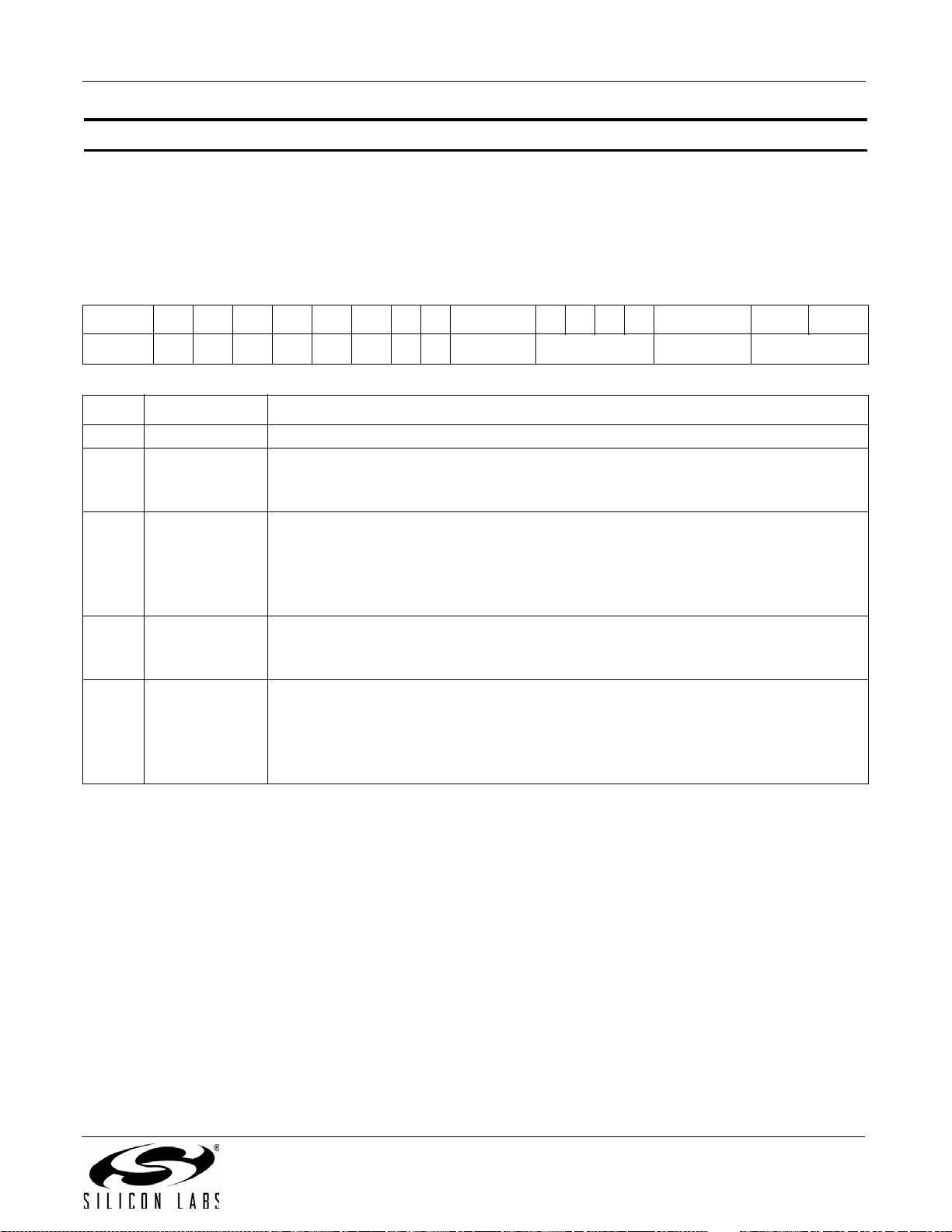
AN332
Property 0x0102. DIGITAL_OUTPUT_FORMAT
Configures the digital audio output format. Configuration options include DCLK edge, data format, force mono, and
sample precision.
Available in: Si4705/06, Si4721/31/35/37/39, Si4730/34/36/38-D60 and later, Si4741/43/45, Si4784/85
Default: 0x0000
Note: DIGITAL_OUTPUT_FORMAT is supported in FM receive component 2.0 or later.
Bit 15141312111098 7 6543 2 1 0
Name
Bit Name Function
15:8 Reserved Always write to 0.
7OFALL
6:3 OMODE[3:0]
2OMONO
1:0 OSIZE[1:0]
00000000OFALL OMODE[3:0] OMONO OSIZE[1:0]
Digital Output DCLK Edge.
0 = use DCLK rising edge
1 = use DCLK falling edge
Digital Output Mode.
0000 = I2S
0110 = Left-justified
1000 = MSB at second DCLK after DFS pulse
1100 = MSB at first DCLK after DFS pulse
Digital Output Mono Mode.
0 = Use mono/stereo blend (per blend thresholds)
1 = Force mono
Digital Output Audio Sample Precision.
0 = 16-bits
1 = 20-bits
2 = 24-bits
3 = 8-bits
Rev. 0.8 85
Page 86
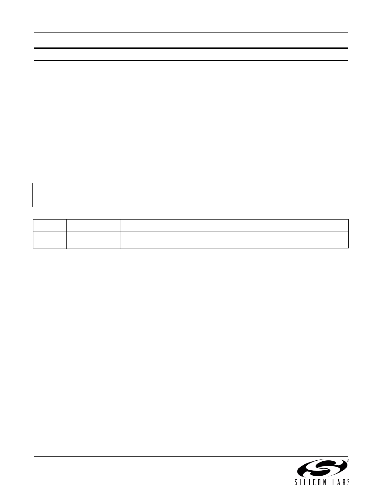
AN332
Property 0x0104. DIGITAL_OUTPUT_SAMPLE_RATE
Enables digital audio output and configures digital audio output sample rate in samples per second (sps). When
DOSR[15:0] is 0, digital audio output is disabled. The over-sampling rate must be set in order to satisfy a minimum
DCLK of 1 MHz. To enable digital audio output, program DOSR[15:0] with the sample rate in samples per second.
The system controller must establish DCLK and DFS prior to enabling the digital audio output else the
device will not respond and will require reset. The sample rate must be set to 0 before the DCLK/DFS is
removed. FM_TUNE_FREQ command must be sent after the POWER_UP command to start the internal
clocking before setting this property.
Note: DIGITAL_OUPTUT_SAMPLE_RATE is supported in FM receive component 2.0 or later.
Available in: Si4705/06, Si4721/31/35/37/39, Si4730/34/36/38-D60 and later, Si4741/43/45, Si4784/85
Default: 0x0000 (digital audio output disabled)
Units: sps
Range: 32–48 ksps, 0 to disable digital audio output
Bit1514131211109876543210
Name
Bit Name Function
15:0 DOSR[15:0]
Digital Output Sample Rate.
32–48 ksps. 0 to disable digital audio output.
DOSR[15:0]
86 Rev. 0.8
Page 87
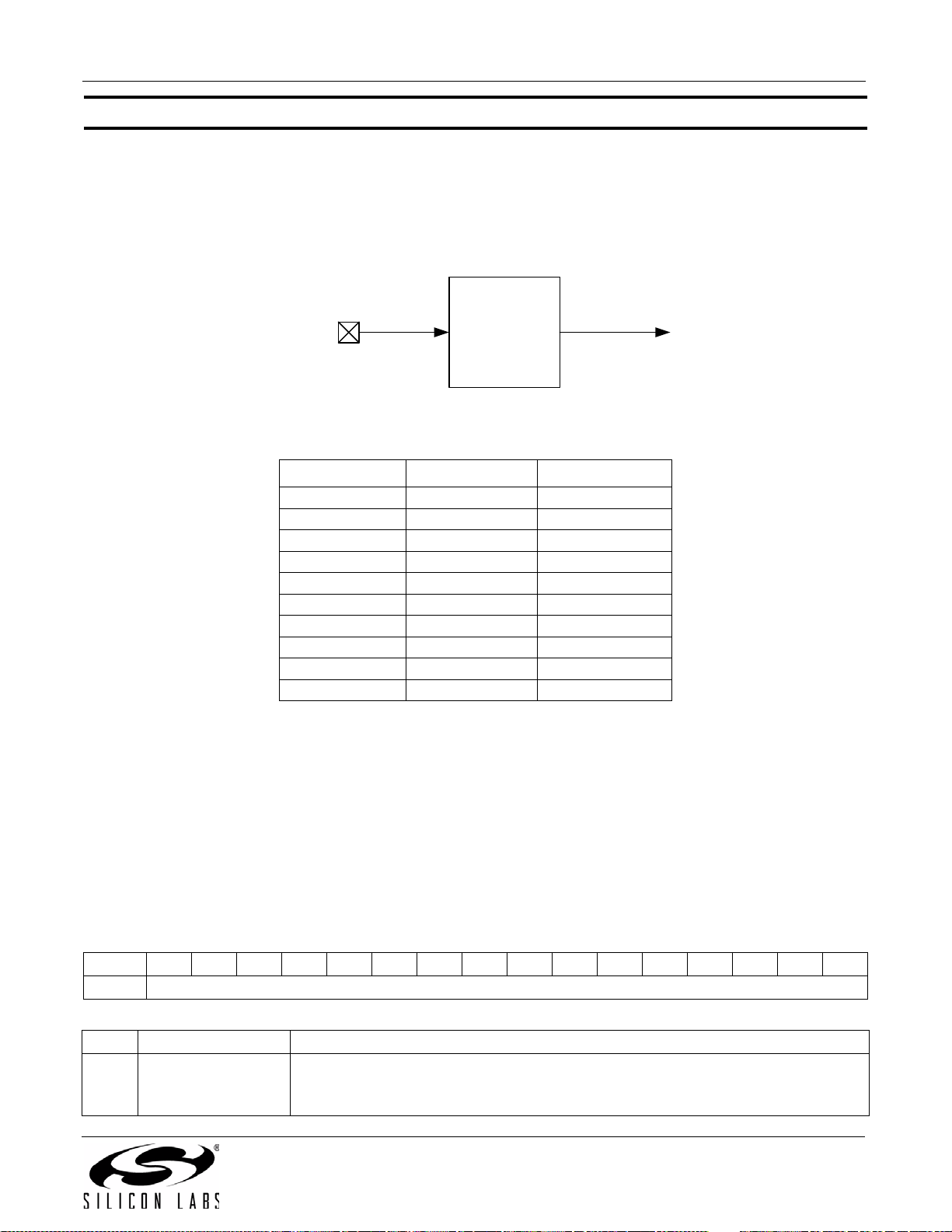
AN332
RCLK REFCLK
PIN 9
Prescaler
Divide by
1-4095
31.130 kHz –
40 MHz
31.130 kHz –
34.406 kHz
Property 0x0201. REFCLK_FREQ
Sets the frequency of the REFCLK from the output of the prescaler. The REFCLK range is 31130 to 34406 Hz
(32768 ±5% Hz) in 1 Hz steps, or 0 (to disable AFC). For example, an RCLK of 13 MHz would require a prescaler
value of 400 to divide it to 32500 Hz REFCLK. The reference clock frequency property would then need to be set to
32500 Hz. RCLK frequencies between 31130 Hz and 40 MHz are supported, however, there are gaps in frequency
coverage for prescaler values ranging from 1 to 10, or frequencies up to 311300 Hz. The following table
summarizes these RCLK gaps.
Figure 2. REFCLK Prescaler
Table 11. RCLK Gaps
Prescaler RCLK Low (Hz) RCLK High (Hz)
1 31130 34406
2 62260 68812
3 93390 103218
4 124520 137624
5 155650 172030
6 186780 206436
7 217910 240842
8 249040 275248
9 280170 309654
10 311300 344060
The RCLK must be valid 10 ns before sending and 20 ns after completing the FM_TUNE_FREQ and
FM_SEEK_START commands. In addition, the RCLK must be valid at all times for proper AFC operation. The
RCLK may be removed or reconfigured at other times. The CTS bit (and optional interrupt) is set when it is safe to
send the next command. This property may only be set or read when in powerup mode. The default is 32768 Hz.
Available in: All
Default: 0x8000 (32768)
Units: 1 Hz
Step: 1 Hz
Range: 31130–34406
Bit D15D14D13D12D11D10D9D8D7D6D5D4D3D2D1D0
Name
Bit Name Function
Frequency of Reference Clock in Hz.
15:0 REFCLKF[15:0]
The allowed REFCLK frequency range is between 31130 and 34406 Hz (32768
±5%), or 0 (to disable AFC).
REFCLKF[15:0]
Rev. 0.8 87
Page 88
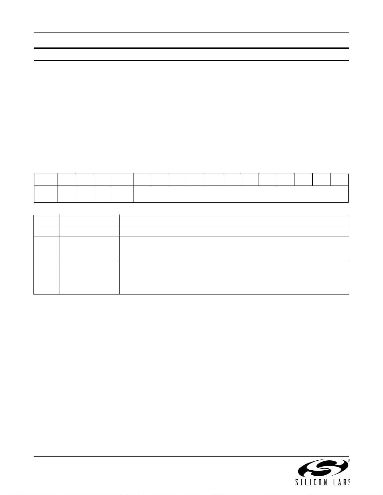
AN332
Property 0x0202. REFCLK_PRESCALE
Sets the number used by the prescaler to divide the external RCLK down to the internal REFCLK. The range may
be between 1 and 4095 in 1 unit steps. For example, an RCLK of 13 MHz would require a prescaler value of 400 to
divide it to 32500 Hz. The reference clock frequency property would then need to be set to 32500 Hz. The RCLK
must be valid 10 ns before sending and 20 ns after completing the FM_TUNE_FREQ and FM_TUNE_START
commands. In addition, the RCLK must be valid at all times for proper AFC operation. The RCLK may be removed
or reconfigured at other times. The CTS bit (and optional interrupt) is set when it is safe to send the next command.
This property may only be set or read when in powerup mode. The default is 1.
Available in: All
Default: 0x0001
Step: 1
Range: 1–4095
BitD15D14D13D12D11D10D9D8D7D6D5D4D3D2D1D0
Name
000
RCLK
SEL
REFCLKP[11:0]
Bit Name Function
15:13 Reserved Always write to 0.
RCLKSEL.
12 RCLKSEL
11:0 REFCL K P [11:0]
0 = RCLK pin is clock source.
1 = DCLK pin is clock source.
Prescaler for Reference Clock.
Integer number used to divide clock frequency down to REFCLK frequency. The
allowed REFCLK frequency range is between 31130 and 34406 Hz (32768 5%), or
0 (to disable AFC).
88 Rev. 0.8
Page 89
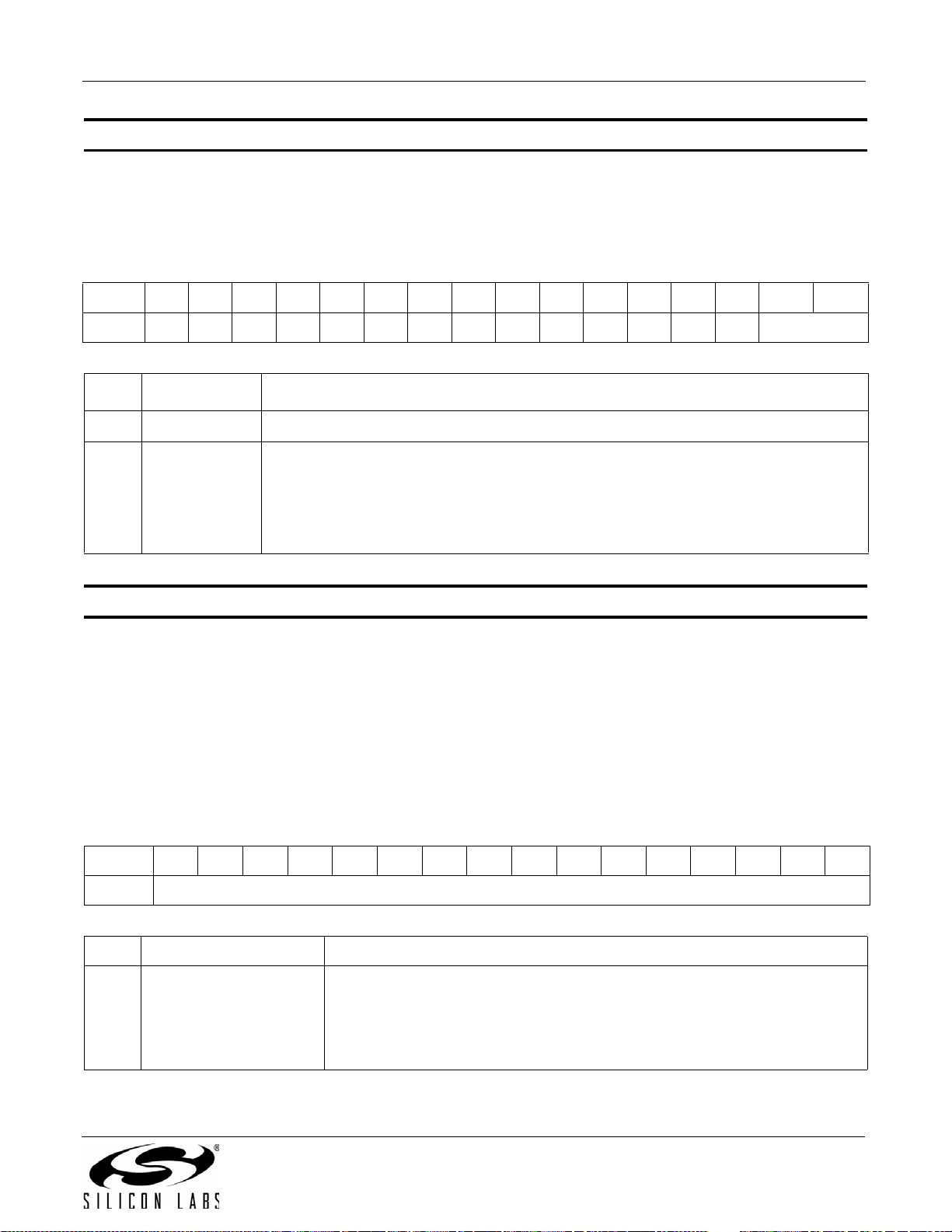
AN332
Property 0x1100. FM_DEEMPHASIS
Sets the FM Receive de-emphasis to 50 or 75 µs. The CTS bit (and optional interrupt) is set when it is safe to send
the next command. This property may only be set or read when in powerup mode. The default is 75 µs.
Available in: All except Si4749
Default: 0x0002
Bit D15D14D13D12D11D10D9D8D7D6D5D4D3D2 D1 D0
Name
Bit Name Function
15:2 Reserved Always write to 0.
1:0 DEEMPH[1:0]
Property 0x11 02. FM_CHANNEL_FILTER
Selects bandwidth of channel filter applied at the demodulation stage. Default is automatic which means the device
automatically selects proper channel filter. The CTS bit (and optional interrupt) is set when it is safe to send the
next command. This property may only be set or read when in powerup mode. The default is 1.
Available in: Si4706, Si4749, Si4704/05/30/31/34/35/84/85-D50 and later
Default: 0x0001 (Si4706, Si4749, Si4705/31/35/85-D50 and later)
00000000000000DEEMPH[1:0]
FM De-Emphasis.
10 = 75 µs. Used in USA (default)
01 = 50 µs. Used in Europe, Australia, Japan
00 = Reserved
11 = Re s e r ved
0x0000 (Si4704/30/34/84-D50 and later)
Range: 0–4
Note: Automatic channel filter setting is not supported in FMRX component 3.0.
Bit D15D14D13D12D11D10D9D8D7D6D5D4D3D2D1D0
Name
Bit Name Function
0 = Automatically select proper channel filter.
1 = Force wide (110 kHz) channel filter.
15:0 FM_CHANNEL_FILTER
2 = Force narrow (84 kHz) channel filter.
3 = Force narrower (60 kHz) channel filter.
4 = Force narrowest (40 kHz) channel filter.
FMCHFILT[15:0]
Rev. 0.8 89
Page 90

AN332
Property 0x1105. FM_BLEND_STEREO_THRESHOLD
Sets RSSI threshold for stereo blend (Full stereo above threshold, blend below threshold). To force stereo, set this
to 0. To force mono, set this to 127. The CTS bit (and optional interrupt) is set when it is safe to send the next
command. This property may only be set or read when in powerup mode. The default is 49 dBµV.
Available in: Si470x/2x, Si473x-C40 and earlier
Default: 0x0031
Units: dBµV
Step: 1
Range: 0–127
Bit D15D14D13D12D11D10D9D8D7D6D5D4D3D2D1D0
Name
Bit Name Function
15:7 Reserved Always write to 0.
6:0 STTHRESH
Property 0x1106. FM_BLEND_MONO_THRESHOLD
Sets RSSI threshold for mono blend (Full mono below threshold, blend above threshold). To force stereo, set this
to 0. To force mono, set this to 127. The CTS bit (and optional interrupt) is set when it is safe to send the next
command. This property may only be set or read when in powerup mode. The default is 30 dBµV.
Available in: Si470x/2x, Si473x-C40 and earlier
Default: 0x001E
Units: dBµV
Step: 1
Range: 0–127
000000000 STTHRESH[6:0]
FM Blend Stereo Threshold.
RSSI threshold below which the audio output goes into a blend mode. Above this
threshold the audio output is in full stereo. Specified in units of dBµV in 1 dB steps
(0–127). Default is 49 dBµV.
Bit D15D14D13D12D11D10D9D8D7D6D5D4D3D2D1D0
Name
Bit Name Function
15:7 Reserved Always write to 0.
6:0 MONOTHRESH
90 Rev. 0.8
000000000 MONOTHRESH[6:0]
FM Blend Mono Threshold.
RSSI threshold below which the audio output goes into full mono mode. Above this
threshold the audio output is in blend or full stereo. Specified in units of dBµV in 1 dB
steps (0–127). Default is 30 dBµV.
Page 91
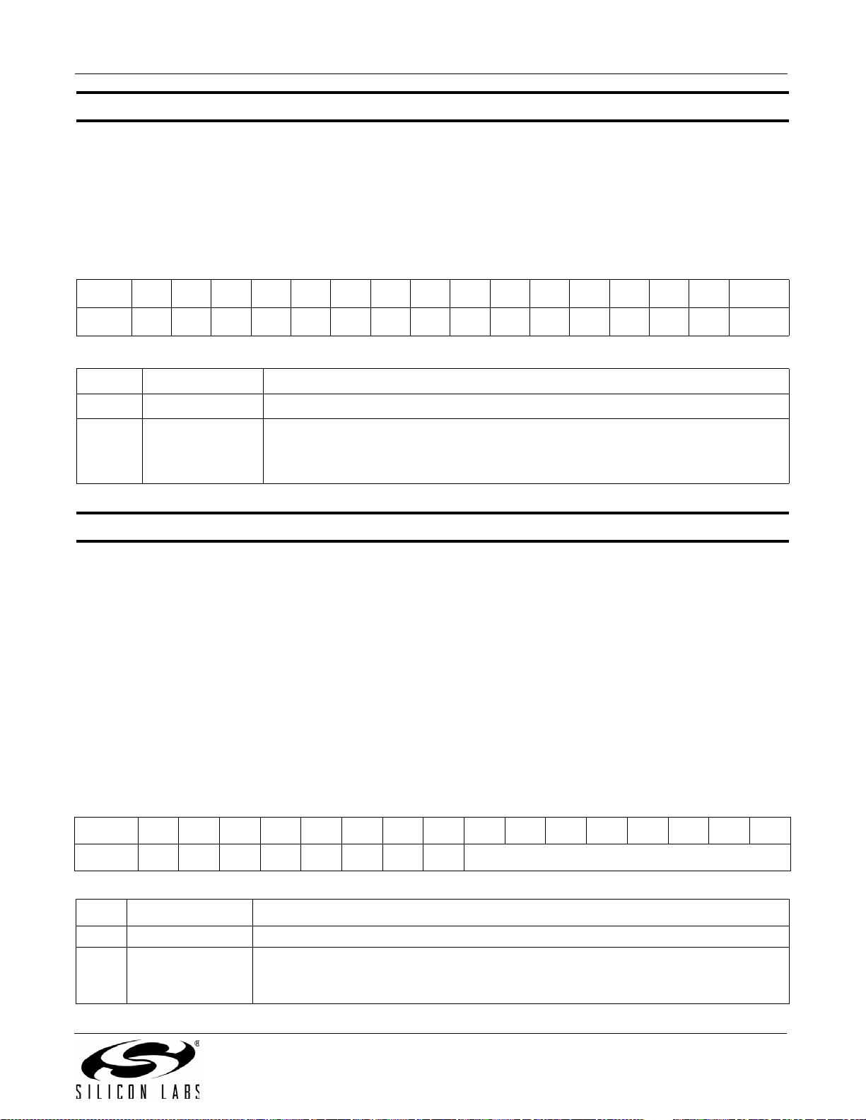
AN332
Property 0x1107. FM_ANTENNA_INPUT
Selects what type of antenna and what pin it is connected to. Default is 0 which means the antenna used is a
headphone (long) antenna and it is connected to the FMI pin. Setting the FMTXO bit to 1 means that the antenna
used is an embedded (short) antenna and it is connected to the TXO/LPI pin.
Note: To assure proper tuning, the FM_TUNE_FREQ command should be issued immediately after this property is changed.
Available in: Si4704/05/06/20/21
Default: 0x0000
Bit D15D14D13D12D11D10D9D8D7D6D5D4D3D2D1 D0
Name
Bit Name Function
15:1 Reserved Always write to 0
Property 0x1108. FM_MAX_TUNE_ERROR
Sets the maximum freq error allowed before setting the AFC rail indicator (AFCRL). The CTS bit (and optional
interrupt) is set when it is safe to send the next command. This property may only be set or read when in powerup
mode. The default is 20 kHz.
Note: For FMRX components 2.0 or earlier, the default is set to 30 kHz. For best seek performance, set
Available in: All
Default: 0x001E (Si473x-B20 and earlier)
000000000000000FMTXO
Selects what type of antenna and which pin it is connected to:
0FMTXO
FM_MAX_TUNE_ERROR to 20 kHz.
0x0014 (all others)
0 = Use FMI pin for headphone (long) antenna
1 = Use TXO/LPI pin for embedded (short) antenna
Units: kHz
Step: 1
Range: 0–255
Bit D15D14D13D12D11D10D9D8D7D6D5D4D3D2D1D0
Name
Bit Name Function
15:8 Reserved Always write to 0.
7:0 FMMAXTUNEERR
00000000 FMMAXTUNEERR[7:0]
FM Maximum Tuning Frequency Error.
Maximum tuning error allowed before setting the AFC Rail Indicator ON. Specified in
units of kHz. Default is 20 kHz.
Rev. 0.8 91
Page 92
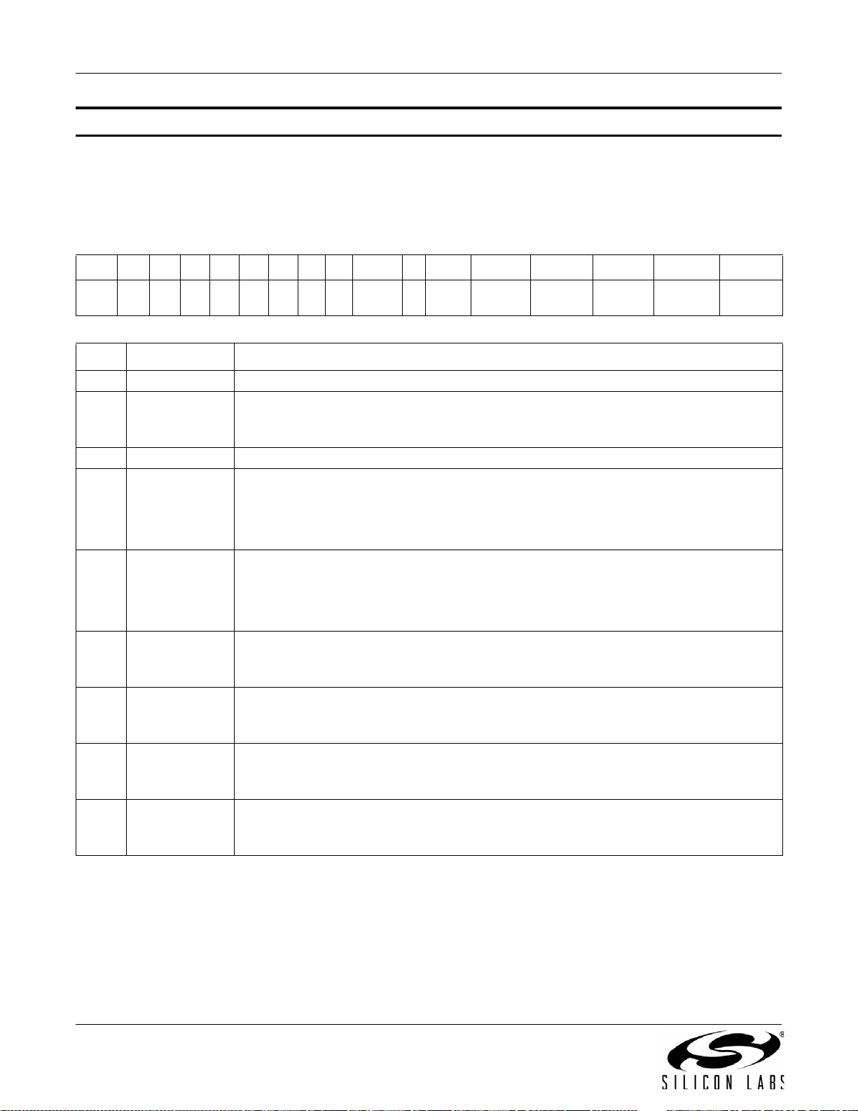
AN332
Property 0x1200. FM_RSQ_INT_SOURCE
Configures interrupt related to Received Signal Quality metrics. The CTS bit (and optional interrupt) is set when it is
safe to send the next command. This property may only be set or read when in powerup mode. The default is 0.
Available in: All
Default: 0x0000
Bit D15 D14 D13 D12 D11 D10 D9 D8 D7 D6 D5 D4 D3 D2 D1 D0
Name
0 0000000
BLEND
IEN
Bit Name Function
15:8 Reserved Always write to 0.
Interrupt Source Enable: Blend.
7BLENDIEN
Enable blend as the source of interrupt which the threshold is set by
FM_RSQ_BLEND_THRESHOLD.
6 Reserved Always write to 0.
Interrupt Source Enable: Multipath High (Si4706-C30 and later , Si474x and
5MULTHIEN
Si4704/05/30/31/34/35/84/85-D50 and later only).
Enable Multipath high as the source of interrupt which the threshold is set by
FM_RSQ_MULTIPATH_HI_THRESHOLD.
0
MULT
HIEN
MULT-
LIEN
SNRHIEN SNRLIEN RSSIHIEN RSSILIEN
Interrupt Source Enable: Multipath Low (Si4706-C30 and later, Si4 74x and
4MULTLIEN
Si4704/05/30/31/34/35/84/85-D50 and later only).
Enable Multipath low as the source of interrupt which the threshold is set by
FM_RSQ_MULTIPATH_LO_THRESHOLD.
Interrupt Source Enable: SNR High.
3 SNRHIEN
Enable SNR high as the source of interrupt which the threshold is set by
FM_RSQ_SNR_HI_THRESHOLD.
Interrupt Source Enable: SNR Low.
2SNRLIEN
Enable SNR low as the as the source of interrupt which the threshold is set by
FM_RSQ_SNR_LO_THRESHOLD.
Interrupt Source Enable: RSSI High.
1 RSSIHIEN
Enable RSSI high as the source of interrupt which the threshold is set by
FM_RSQ_RSSI_HI_THRESHOLD.
Interrupt Source Enable: RSSI Low.
0 RSSILIEN
Enable RSSI low as the source of interrupt which the threshold is set by
FM_RSQ_RSSI_LO_THRESHOLD.
92 Rev. 0.8
Page 93
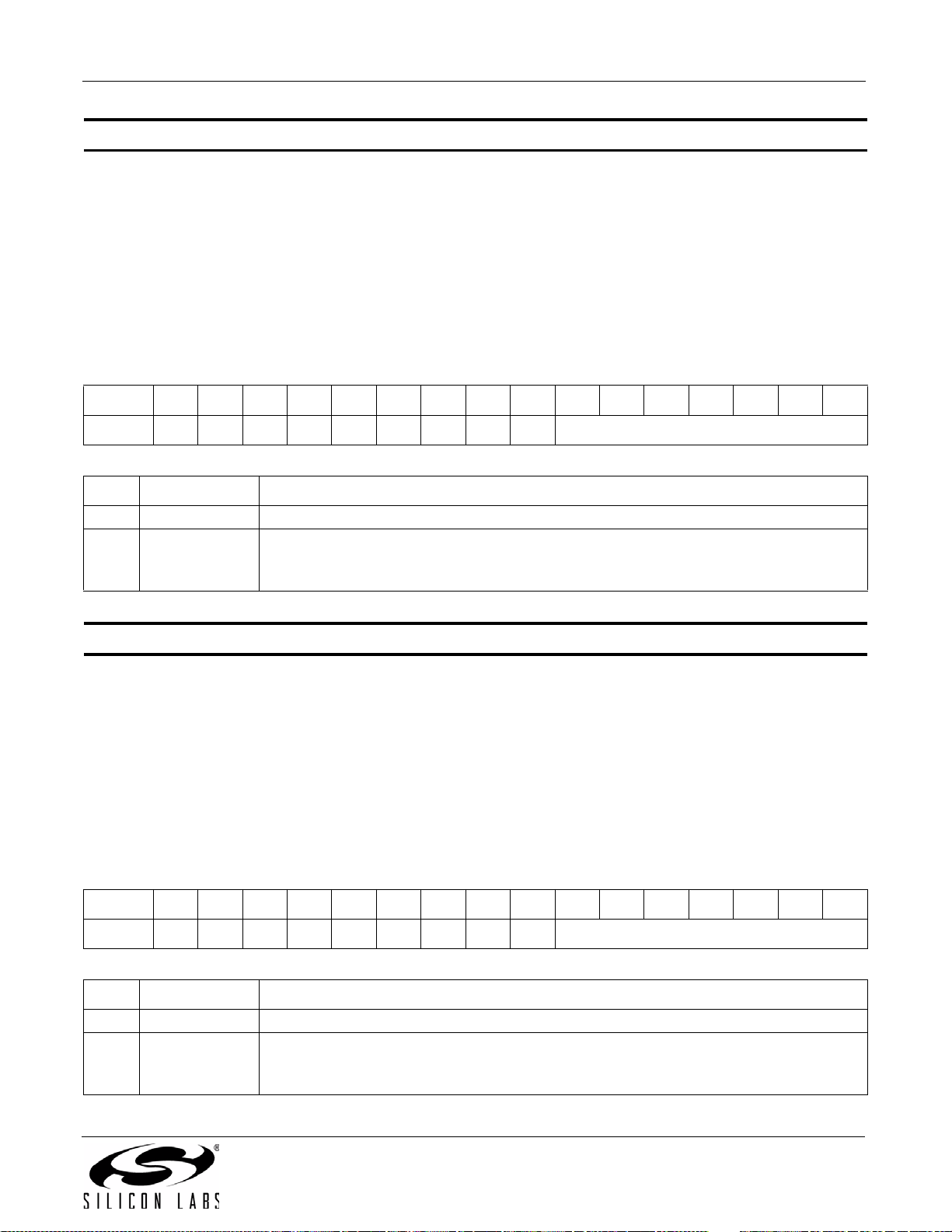
AN332
Property 0x1201. FM_RSQ_SNR_HI_THRESHOLD
Sets high threshold which triggers the RSQ interrupt if the SNR is above this threshold. The CTS bit (and optional
interrupt) is set when it is safe to send the next command. This property may only be set or read when in powerup
mode. The default is 127dB.
Available in: All
Default: 0x007F
Units: dB
Step: 1
Range: 0–127
Bit D15D14D13D12D11D10D9D8D7D6D5D4D3D2D1D0
Name
Bit Name Function
15:7 Reserved Always write to 0.
6:0 SNRH
Property 0x1202. FM_RSQ_SNR_LO_THRESHOLD
Sets low threshold which triggers the RSQ interrupt if the SNR is below this threshold. The CTS bit (and optional
interrupt) is set when it is safe to send the next command. This property may only be set or read when in powerup
mode. The default is 0 dB.
Available in: All
Default: 0x0000
Units: dB
Step: 1
Range: 0–127
0 0 0 0 0 0 0 0 0 SNRH[6:0]
FM RSQ SNR High Threshold.
Threshold which triggers the RSQ interrupt if the SNR is above this threshold. Specified
in units of dB in 1 dB steps (0–127). Default is 127 dB.
Bit D15D14D13D12D11D10D9D8D7D6D5D4D3D2D1D0
Name
Bit Name Function
15:7 Reserved Always write to 0.
6:0 SNRL
000000000 SNRL[6:0]
FM RSQ SNR Low Threshold.
Threshold which triggers the RSQ interrupt if the SNR is below this threshold. Specified
in units of dB in 1 dB steps (0–127). Default is 0 dB.
Rev. 0.8 93
Page 94
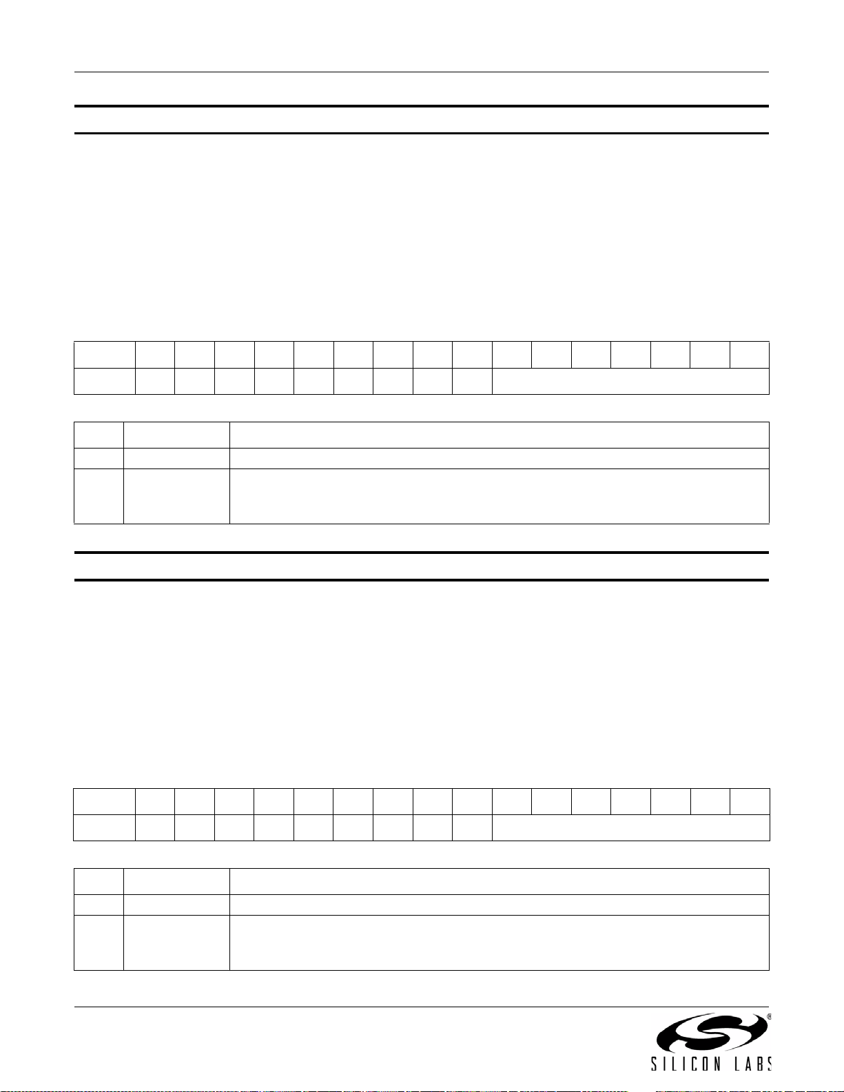
AN332
Property 0x1203. FM_RSQ_RSSI_HI_THRESHOLD
Sets high threshold which triggers the RSQ interrupt if the RSSI is above this threshold. The CTS bit (and optional
interrupt) is set when it is safe to send the next command. This property may only be set or read when in powerup
mode. The default is 127 dBµV.
Available in: All
Default: 0x007F
Units: dBµV
Step: 1
Range: 0–127
Bit D15D14D13D12D11D10D9D8D7D6D5D4D3D2D1D0
Name
Bit Name Function
15:7 Reserved Always write to 0.
6:0 RSSIH
Property 0x1204. FM_RSQ_RSSI_LO_THRESHOLD
Sets low threshold which triggers the RSQ interrupt if the RSSI is below this threshold. The CTS bit (and optional
interrupt) is set when it is safe to send the next command. This property may only be set or read when in powerup
mode. The default is 0 dBµV.
Available in: All
Default: 0x0000
Units: dBµV
Step: 1
Range: 0–127
000000000 RSSIH[6:0]
FM RSQ RSSI High Threshold.
Threshold which triggers the RSQ interrupt if the RSSI is above this threshold. Specified
in units of dBµV in 1 dB steps (0–127). Default is 127 dBµV.
Bit D15D14D13D12D11D10D9D8D7D6D5D4D3D2D1D0
Name
Bit Name Function
15:7 Reserved Always write to 0.
6:0 RSSIL
94 Rev. 0.8
000000000 RSSIL[6:0]
FM RSQ RSSI Low Threshold.
Threshold which triggers the RSQ interrupt if the RSSI is below this threshold. Specified
in units of dBµV in 1 dB steps (0–127). Default is 0 dBµV.
Page 95
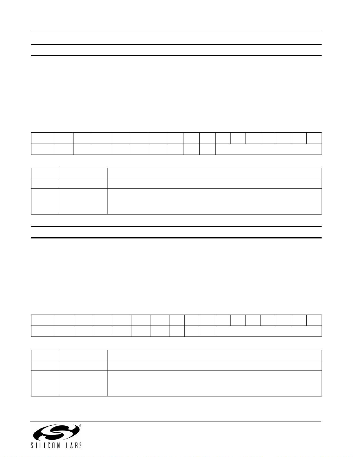
AN332
Property 0x1205. FM_RSQ_MULTIPATH_HI_THRESHOLD
Sets the high threshold which triggers the RSQ interrupt if the Multipath level is above this threshold. The CTS bit
(and optional interrupt) is set when it is safe to send the next command. This property may only be set or read
when in power up mode. The value may be the threshold multipath percent (0–100), or 127 to disable the feature.
Available in: Si4706-C30 and later, Si474x, Si4704/05/30/31/34/35/84/85-D50 and later
Default: 0x007F
Step: 1
Range: 0–127
Bit D15D14D13D12D11D10D9D8D7D6D5D4D3D2D1D0
Name 0 0 0 0 0 0 0 0 0 MULTH[6:0]
Bit Name Function
15:7 Reserved Always write to 0.
6:0 MULTH
Property 0x1206. FM_RSQ_MULTIPATH_LO_THRESHOLD
Sets the low threshold which triggers the RSQ interrupt if the Multipath level is below this threshold. The CTS bit
(and optional interrupt) is set when it is safe to send the next command. This property may only be set or read
when in power up mode. The default is 0.
Available in: Si4706-C30 and later, Si474x, Si4704/05/30/31/34/35/84/85-D50 and later
Default: 0x0000
Step: 1
Range: 0–127
Bit D15 D14D13D12D11D10D9D8D7D6D5D4D3D2D1D0
Name 0 00000000 MULTL[6:0]
Bit Name Function
FM RSQ Multipath High Threshold.
Threshold which triggers the RSQ interrupt if the Multipath is above this threshold.
Default is 127.
15:7 Reserved Always write to 0
6:0 MULTL
FM RSQ Multipath Low Threshold.
Threshold which triggers the RSQ interrupt if the Multipath is below this threshold.
Default is 0.
Rev. 0.8 95
Page 96
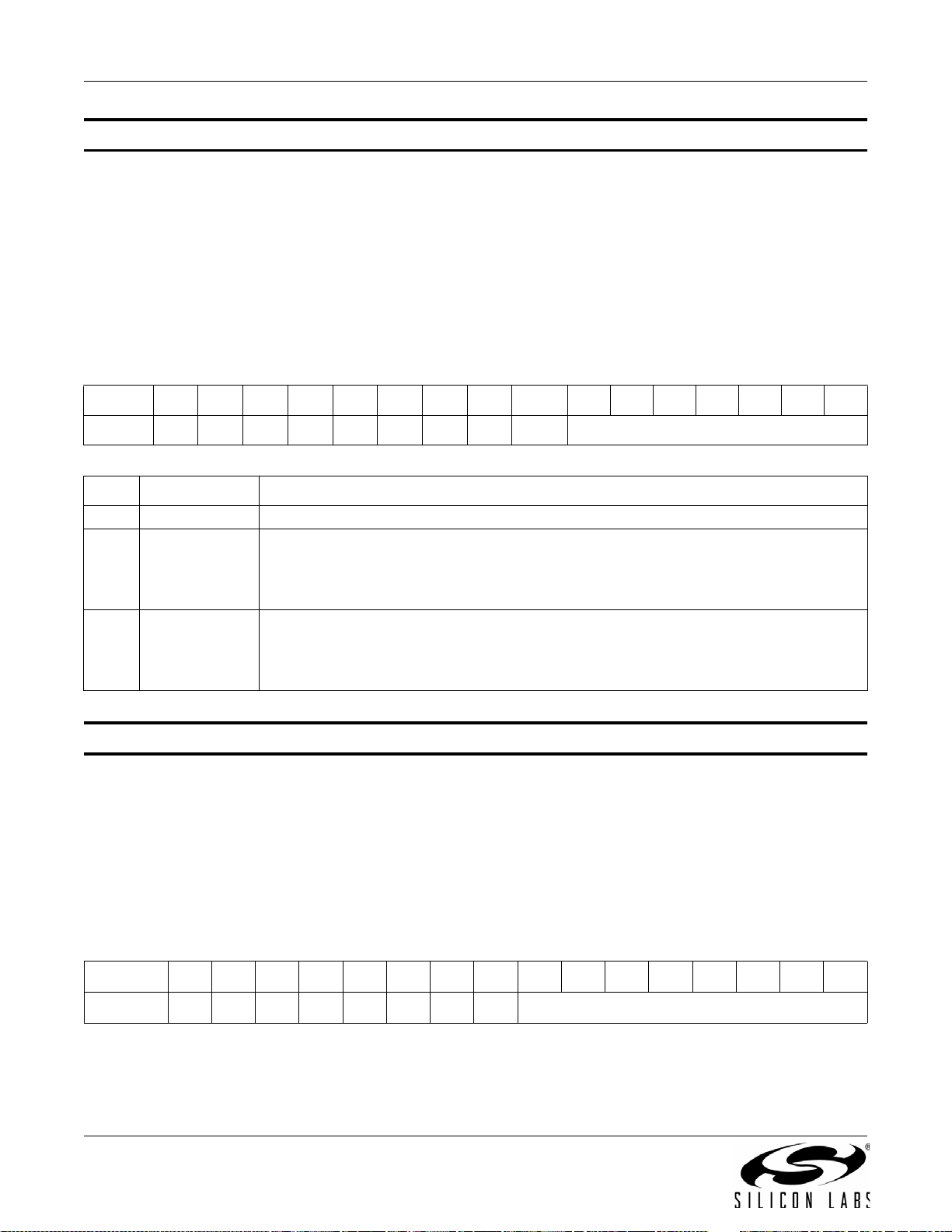
AN332
Property 0x1207. FM_RSQ_BLEND_THRESHOLD
Sets the blend threshold for blend interrupt when boundary is crossed. The CTS bit (and optional interrupt) is set
when it is safe to send the next command. This property may only be set or read when in powerup mode. The
default is 1%.
Available in: All except Si4749
Default: 0x0081
Units: %
Step: 1
Range: 0–100
Bit D15D14D13D12D11D10D9D8 D7 D6D5D4D3D2D1D0
Name
Bit Name Function
15:8 Reserved Always write to 0.
7PILOT
6:0 BLEND
Property 0x1300. FM_SOFT_MUTE_RATE
Sets the attack and decay rates when entering and leaving soft mute. Later values increase rates, and lower values
decrease rates. The CTS bit (and optional interrupt) is set when it is safe to send the next command. This property
may only be set or read when in powerup mode. The default is 0x0040.
Available in: Si4706/07/20/21/84/85-B20 and earlier, Si4704/05/3x-C40 and earlier
Default: 64
00000000PILOT BLEND[6:0]
Pilot Indicator.
This bit has to be set to 1 (there has to be a pilot present) in order for
FM_RSQ_BLEND_THRESHOLD to trigger an interrupt. Without a pilot tone, the part is
always in full mono mode and never goes into blend.
FM RSQ Blend Threshold.
This is a boundary cross threshold. If the blend cross from above to below, or the other
way around from below to above this threshold, it will trigger an interrupt. Specified in
units of % in 1% steps (0–100). Default is 1%.
Step: 1
Range: 1—255
Bit D15D14D13D12D11D10D9D8D7D6D5D4D3D2D1D0
Name
96 Rev. 0.8
00000000 SMRATE[7:0]
Page 97
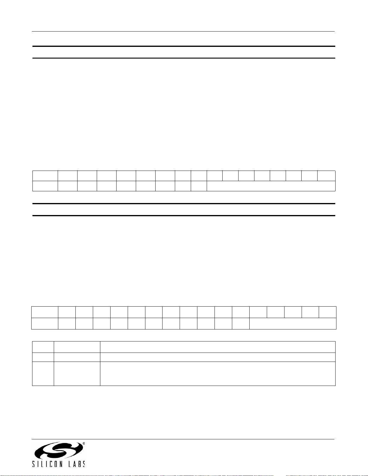
AN332
Property 0x1301. FM_SOFT_MUTE_SLOPE
Configures attenuation slope during soft mute in dB attenuation per dB SNR below the soft mute SNR threshold.
Soft mute attenuation is the minimum of SMSLOPE x (SMTHR – SNR) and SMATTN. The recommended
SMSLOPE value is CEILING(SMATTN/SMTHR). SMATTN and SMTHR are set via the
FM_SOFT_MUTE_MAX_ATTENUATION and FM_SOFT_MUTE_SNR_THRESHOLD properties. The CTS bit
(and optional interrupt) is set when it is safe to send the next command. This property may only be set or read
when in power up mode. The default soft mute slope property setting is 2 dB/dB in supported devices. The soft
mute slope is not configurable in Si4704/05/3x-B20 devices (those with FMRX component 2.0) and is 2 dB/dB. The
soft mute slope is not configurable in Si4710/20-A10 devices (those with FMRX component 1.0), and is 0 dB/dB
(disabled).
Available in: Si4704/05/06/3x-C40 and later, Si4740/41/42/43/44/45
Default: 0x0002
Range: 0–63
Bit D15D14D13D12D11D10D9D8D7D6D5D4D3D2D1D0
Name
Property 0x1302. FM_SOFT_MUTE_MAX_ATTENUATION
Sets maximum attenuation during soft mute (dB). Set to 0 to disable soft mute. The CTS bit (and optional interrupt)
is set when it is safe to send the next command. This property may only be set or read when in powerup mode. The
default is 16 dB.
Available in: All except Si4749
Default: 0x0010
Units: dB
Step: 1
Range: 0–31
Bit D15D14D13D12D11D10D9D8D7D6D5D4D3D2D1D0
Name
Bit Name Function
15:5 Reserved Always write to 0.
4:0 SMATTN
00000000 SMSLOPE[7:0]
00000000000 SMATTN[4:0]
FM Soft Mute Maximum Attenuation.
Set maximum attenuation during soft mute. If set to 0, then soft mute is disabled. Specified in units of dB in 1 dB steps (0–31). Default is 16 dB.
Rev. 0.8 97
Page 98
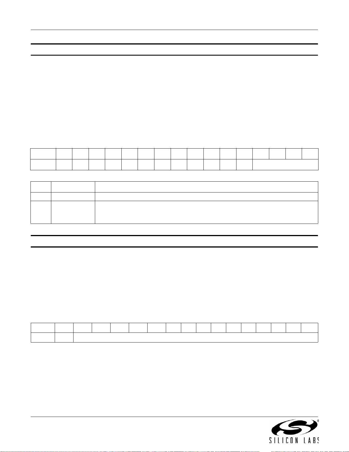
AN332
Property 0x1303. FM_SOFT_MUTE_SNR_THRESHOLD
Sets SNR threshold to engage soft mute. Whenever the SNR for a tuned frequency drops below this threshold, the
FM reception will go in soft mute, provided soft mute max attenuation property is non-zero. The CTS bit (and
optional interrupt) is set when it is safe to send the next command. This property may only be set or read when in
powerup mode. The default is 4 dB.
Available in: All except Si4749
Default: 0x0004
Units: dB
Step: 1
Range: 0–15
Bit D15D14D13D12D11D10D9D8D7D6D5D4D3D2D1D0
Name
Bit Name Function
15:4 Reserved Always write to 0.
3:0 SMTHR
Property 0x1304. FM_SOFT_MUTE_RELEASE_RATE
Sets the soft mute release rate. Smaller values provide slower release and larger values provide faster release.
The CTS bit (and optional interrupt) is set when it is safe to send the next command. This property may only be set
or read when in powerup mode. The default is 8192 (approximately 8000 dB/s).
Release Rate (dB/s) = RELEASE[14:0]/1.024
Available in: Si4706-C30 and later, Si4740/41/42/43/44/45, Si4704/05/30/31/34/35/84/85-D50 and later
Default: 0x2000
Range: 1–32767
Bit D15D14D13D12D11D10D9D8D7D6D5D4D3D2D1D0
Name
000000000000 SMTHR[3:0]
FM Soft Mute SNR Threshold.
Threshold which will engage soft mute if the SNR falls below this. Specified in units of dB
in 1 dB steps (0–15). Default is 4 dB.
0 RELEASE[14:0]
98 Rev. 0.8
Page 99
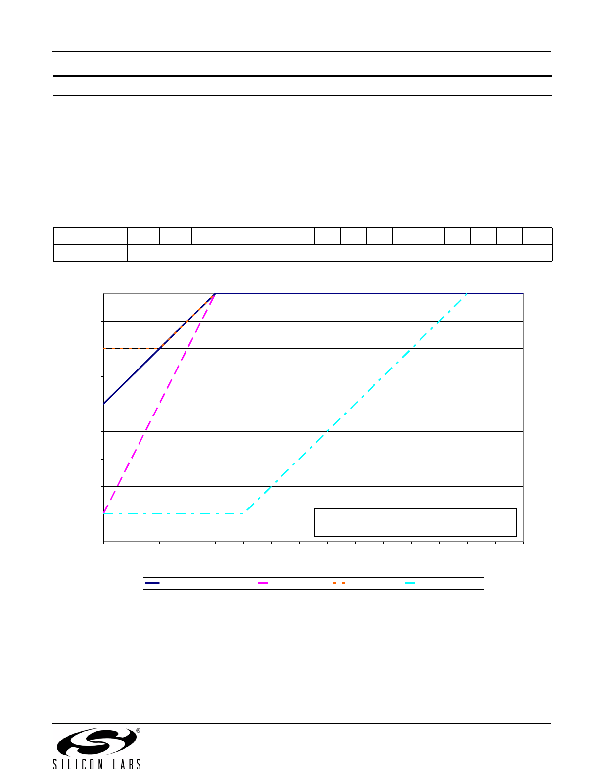
AN332
Softmute Gain (dB)
-18
-16
-14
-12
-10
-8
-6
-4
-2
0
0123456789101112131415
SNR (dB)
x=2, y=16, z=4 (Default) x=4, y=16, z=4 x=2, y=4, z=4 x=2, y=16, z=13
x = 0x1301: FM_SO F T_MUTE_SLOP E (0-63 d B/dB)
y = 0x1302: FM_SOFT _MUTE_MAX_ATTENUATION (0-31 dB)
z = 0x1303 : FM _S O FT _MUTE_SNR_THRESHOLD (0-15 dB)
Property 0x1305. FM_SOFT_MUTE_ATTACK_RATE
Sets the soft mute attack rate. Smaller values provide slower attack and larger values provide faster attack. The
CTS bit (and optional interrupt) is set when it is safe to send the next command. This property may only be set or
read when in powerup mode. The default is 8192 (approximately 8000 dB/s).
Attack Rate (dB/s) = ATTACK[14:0]/1.024
Available in: Si4706-C30 and later, Si4740/41/42/43/44/45, Si4704/05/30/31/34/35/84/85-D50 and later
Default: 0x2000
Range: 1–32767
Bit D15D14D13D12D11D10D9D8D7D6D5D4D3D2D1D0
Name
0 ATTACK[14:0]
Figure 3. Softmute Gain (dB)
Rev. 0.8 99
Page 100
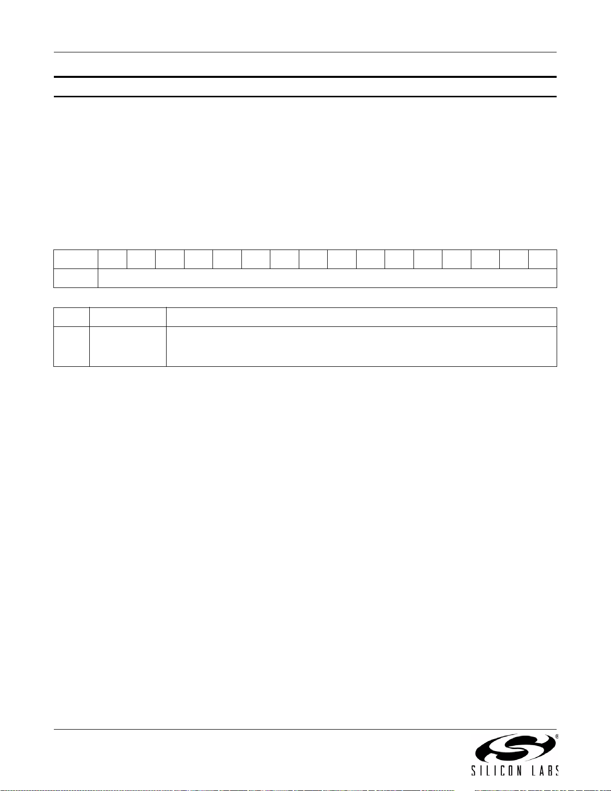
AN332
Property 0x1400. FM_SEEK_BAND_BOTTOM
Sets the bottom of the FM band for seek. The CTS bit (and optional interrupt) is set when it is safe to send the next
command. This property may only be set or read when in powerup mode. The default is 87.5 MHz.
Available in: All
Default: 0x222E
Units: 10 kHz
Step: 50 kHz
Range: 64–108 MHz
Note: For FMRX components 2.0 or earlier, range is 76–108 MHz.
Bit D15D14D13D12D11D10D9D8D7D6D5D4D3D2D1D0
Name
Bit Name Function
FM Seek Band Bottom Frequency.
15:0 FMSKFREQL
Selects the bottom of the FM Band during Seek. Specified in units of 10 kHz. Default is
8750 (87.5 MHz).
FMSKFREQL[15:0]
100 Rev. 0.8
 Loading...