

Page 1
User Manual
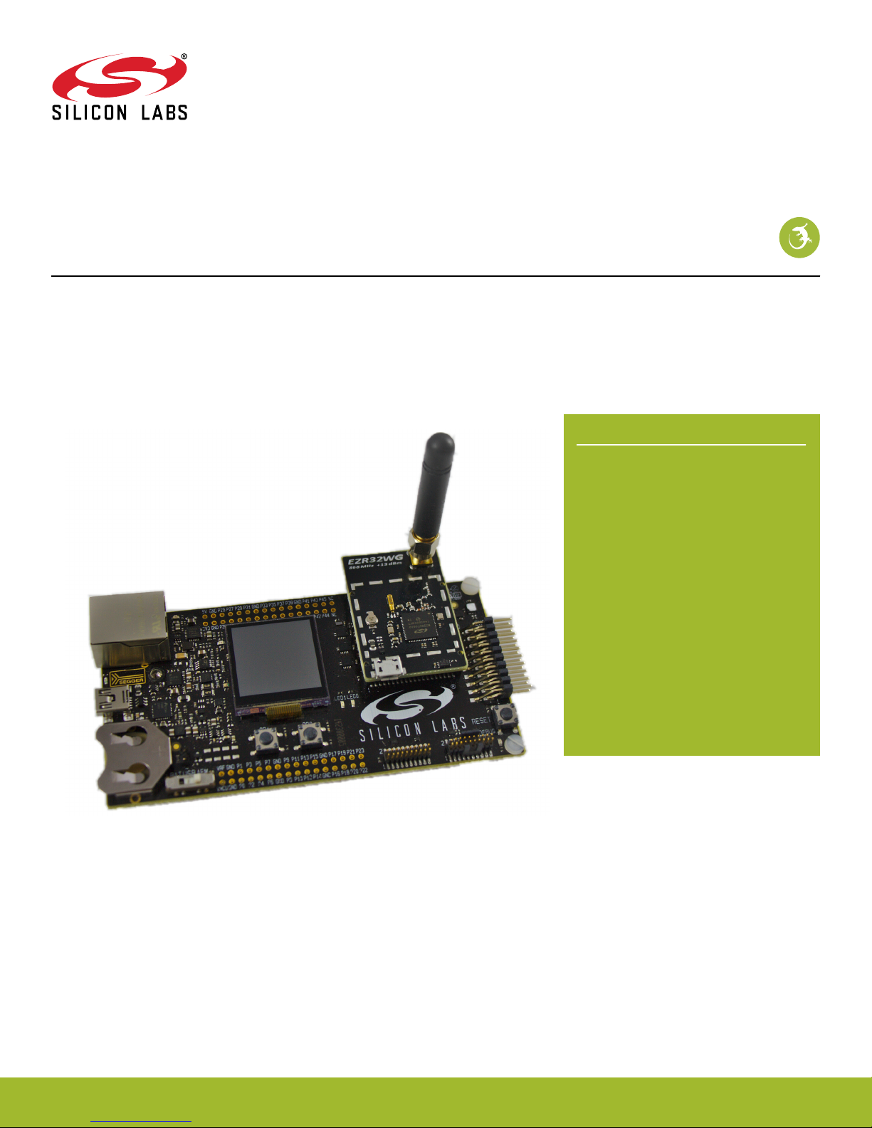
EZR32WG 915MHz Wireless Starter Kit
The WSTK6222 is an excellent starting point to get familiar with
the EZR32 Wonder Gecko Wireless Microcontrollers.
The Wireless Starter Kit Mainboard contains sensors and peripherals demonstrating
some of the Wireless MCU's many capabilities. The kit provides all necessary tools for
developing a Silicon Labs wireless application.
KIT FEATURES
• Ethernet and USB connectivity
• Advanced Energy Monitoring
• Packet Trace Interface support
• SEGGER J-Link OB debugger
• Debug Multiplexer supporting external
hardware as well as radio board
• Silicon Labs' Si7021 Relative Humidity and
Temperature sensor
• Ultra Low power 128x128 pixel Memory
LCD
• LEDs / Pushbuttons / Reset button
• 20pin 2.54mm header for expansion
boards
• Breakout pads for direct access to all radio
I/O pins
• Power sources including USB and CR2032
coin cell holder.
ORDERING INFO
• SLWSTK6222A
silabs.com | Smart. Connected. Energy-friendly. Rev. 1.2
RADIO BOARD FEATURES
• EZR32WG330F256R63G MCU with 256
kB Flash and 32 kB RAM.
• SMA antenna connector
• USB Micro-B connector
• Backup domain capcitor
SOFTWARE SUPPORT
• Simplicity Studio
• Simplicity Profiler
• Simplicity Network Analyzer
• Extensive example set for radio
• Kit Board Support Package
Page 2

EZR32WG 915MHz Wireless Starter Kit
Table of Contents
1. Introduction ................................1
1.1 Description ...............................1
1.2 Kit Content ...............................1
1.3 Getting Started .............................1
2. Kit Block Diagram .............................2
3. Kit Hardware Layout ............................3
4. Power Supply and Reset ...........................4
4.1 MCU Power Selection ...........................4
4.2 Board Controller Power...........................4
4.3 Backup Power Domain ...........................4
4.4 MCU Reset...............................5
4.5 Board Controller Reset ...........................5
5. Peripherals ................................6
5.1 Push Buttons and LEDs ..........................6
5.2 Memory LCD-TFT Display..........................7
5.3 Backup Domain Capacitor..........................7
5.4 USB Micro-B Connector ..........................8
5.5 Si7021 Relative Humidity and Temperature Sensor .................9
6. Advanced Energy Monitor .........................10
6.1 Introduction...............................10
6.2 Advanced Energy Monitor - Theory of operation ..................10
6.3 AEM accuracy and performance........................11
6.4 Usage ................................11
7. Board Controller .............................12
7.1 VCOM ................................12
8. Board Support Package ..........................13
8.1 Application Programming Interface .......................13
8.2 Example Applications ...........................13
8.3 How to include in your own applications .....................13
9. Connectors ...............................14
9.1 Radio Board breakout pads .........................14
9.2 Debug Connector (DBG) ..........................15
9.3 Simplicity Connector............................16
9.4 Expansion header ............................17
10. Integrated Development Environments ....................20
Table of Contents ii
Page 3

EZR32WG 915MHz Wireless Starter Kit
10.1 IAR Embedded Workbench for ARM ......................20
10.2 Atollic TrueSTUDIO for ARM ........................21
10.3 Rowley Associates - CrossWorks for ARM ....................21
10.4 Keil - MDK-ARM ............................21
11. Kit Manager and Upgrades .........................22
11.1 Kit Manager Operation ..........................22
11.2 Firmware Upgrades ...........................22
12. Schematics, Assembly Drawings and BOM ..................23
13. Kit Revision History and Errata .......................24
13.1 Revision History.............................24
13.2 Errata ................................24
14. Document Revision History ........................25
Table of Contents iii
Page 4
EZR32WG 915MHz Wireless Starter Kit
Introduction
1. Introduction
1.1 Description
The idea behind the WSTK6222 is to provide a complete development platform for Silicon Labs EZR32 Wonder Gecko Wireless Microcontrollers. The core of the WSTK6222 is the Wireless Starter Kit (WSTK) Mainboard (BRD4001) which feature an on-board J-Link debugger, an Advanced Energy Monitor for real-time current and voltage monitoring, a Virtual COM port interface, and access to the
Packet Trace Interface (PTI). The WSTK Mainboard is paired with an EZR32 Wonder Gecko radio board that plugs directly into the
mainboard. The radio board feature the EZR32 Wonder Gecko itself and the RF interface. All debug functionality, including AEM,
VCOM and PTI, can also be used towards an external target instead of the included radio board. To further enhance the WSTK usability, the WSTK Mainboard contains sensors and peripherals demonstrating some of the Wireless MCU's many capabilities.
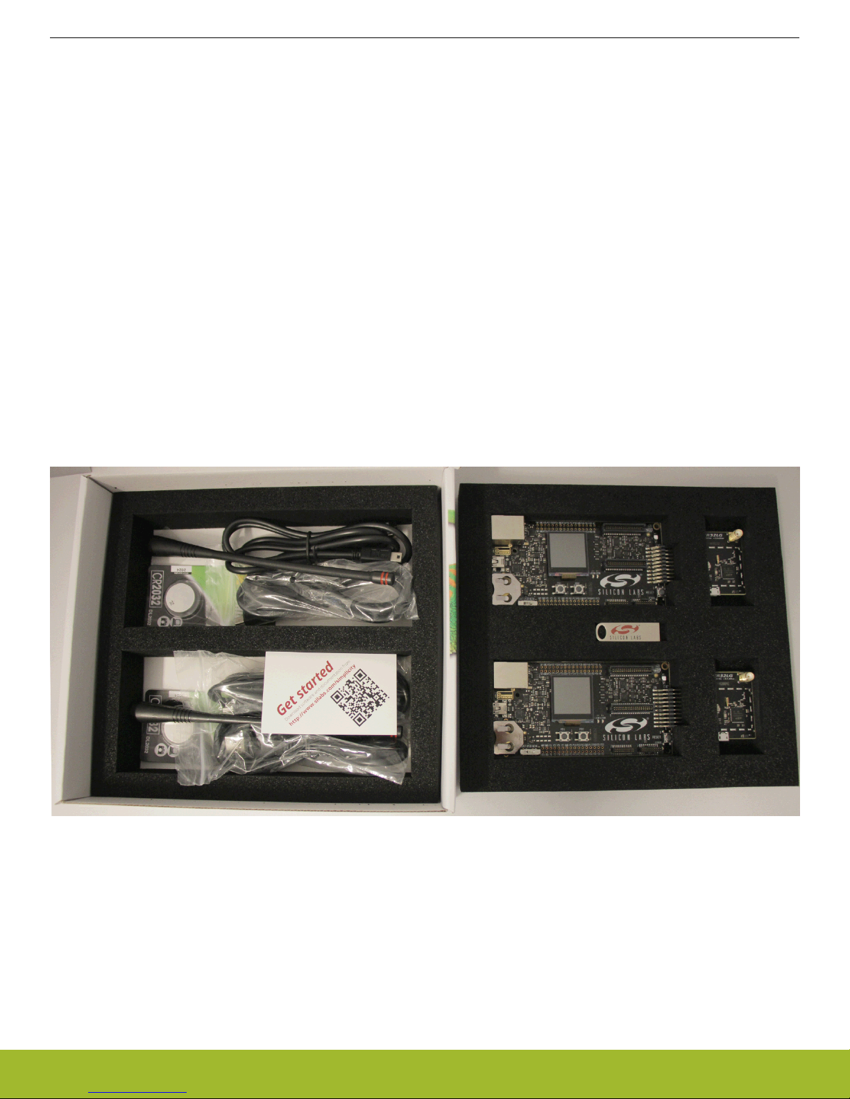
1.2 Kit Content
The following items are contained in the box:
• 2x BRD4001A Wireless Starter Kit Mainboards
• 2x BRD4503B EZR32 Wonder Gecko 915 MHz WSTK Radio Boards
• 2x 915 MHz antennas with SMA connector
• 2x CR2032 Lithium batteries
• 2x USB Type A <-> USB Mini-B cables
• 2x USB Type A <-> USB Micro-B cables
Figure 1.1 WSTK6222 Kit Content on page 1 shows the kit content.
Figure 1.1. WSTK6222 Kit Content
1.3 Getting Started
Detailed instructions for how to get started with your new WSTK6222 can be found on the Silicon Labs Simplicity web pages:
http://www.silabs.com/simplicity
silabs.com | Smart. Connected. Energy-friendly. Rev. 1.2 | 1
Page 5
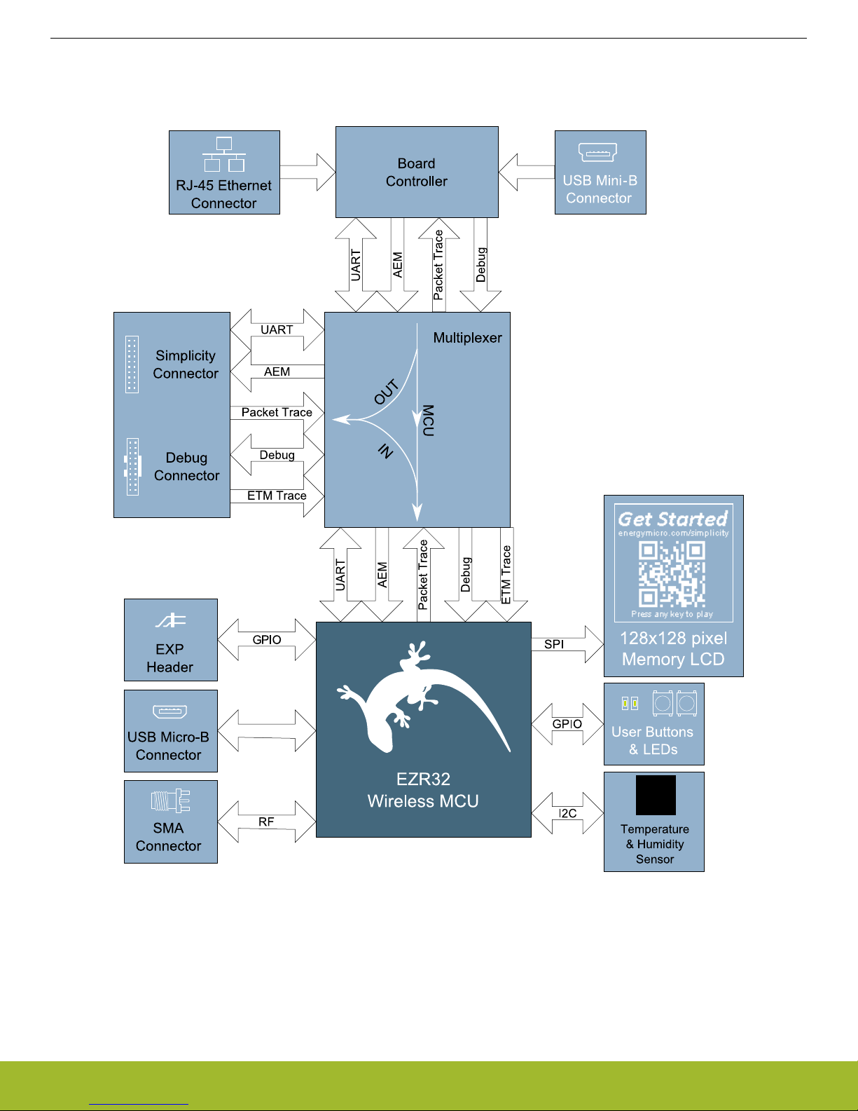
2. Kit Block Diagram
An overview of the EZR32WG 915MHz Wireless Starter Kit is shown in the figure below.
EZR32WG 915MHz Wireless Starter Kit
Kit Block Diagram
silabs.com | Smart. Connected. Energy-friendly. Rev. 1.2 | 2
Figure 2.1. WSTK6222 Block Diagram
Page 6
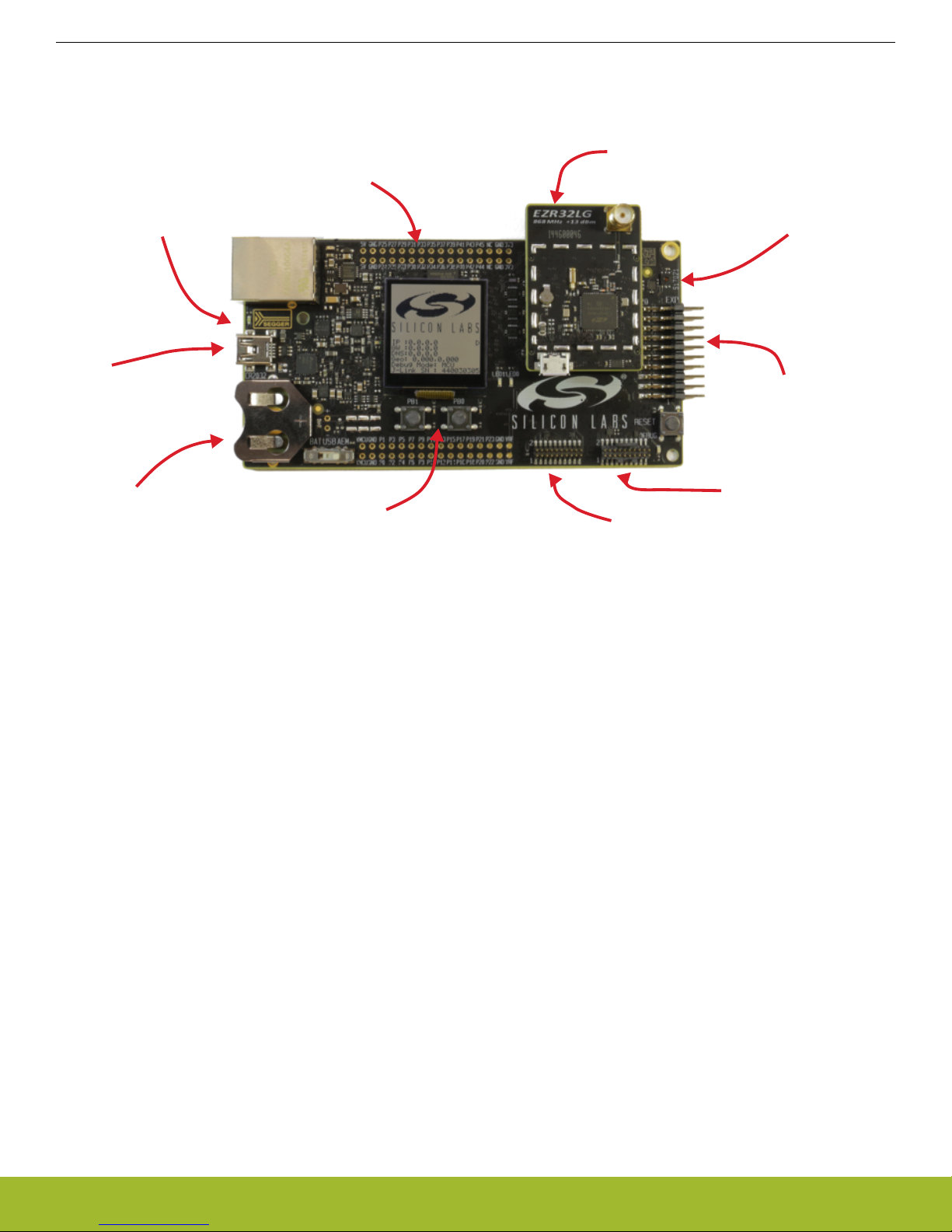
3. Kit Hardware Layout
On-board USB and
Ethernet J-Link
Debugger
SoC / Radio pin
access headers
EZR32 Radioboard
Si7021 Humidity and
Temperature Sensor
EXP-header for
expansion boards
Serial-port, packet trace and Advanced
Energy Monitoring header
ARM Coresight 19-pin
trace/debug header
Ultra-low power 128x128
pixel memory LCD,
buttons and LEDs
Battery or
USB power
USB-serial-port
Packet-trace
Advanced Energy
Monitoring
The layout of the EZR32WG 915MHz Wireless Starter Kit is shown below.
EZR32WG 915MHz Wireless Starter Kit
Kit Hardware Layout
The kit consists of two BRD4001 Wireless Starter Kit Mainboards paired with two BRD4503B plug-in radio boards with the following
specifications:
• Wireless MCU: EZR32WG330F256R63G
• CPU core: ARM Cortex-M4
• Flash memory: 256 kB
• RAM: 32 kB
• Sub-GHz transceiver integrated in the Wireless MCU: EZRadioPRO
• Operation frequency: 915 MHz
• Transmit power: 20 dBm
• Single antenna connector both for transmit and receive
• Crystals for LFXO and HFXO: 32.768kHz and 48 MHz.
• Crystal for RF: 30 MHz
• Backup Power Domain Capacitor
• Full speed USB 2.0 (12 Mbps)
Figure 3.1. WSTK6222 hardware layout
silabs.com | Smart. Connected. Energy-friendly. Rev. 1.2 | 3
Page 7
3.3V
VMCU
AEM
USB
BAT
USB Mini-B
Connector
Advanced
Energy
Monitor
5V
3V Lithium Battery
(CR2032 )
Wireless
MCU
USB Micro-B
Connector
USB_VREGI
(5V)
USB_VREGO
(3.3V)
.
B
A
T
U
SB
AE
M
LDO
EZR32WG 915MHz Wireless Starter Kit
Power Supply and Reset
4. Power Supply and Reset
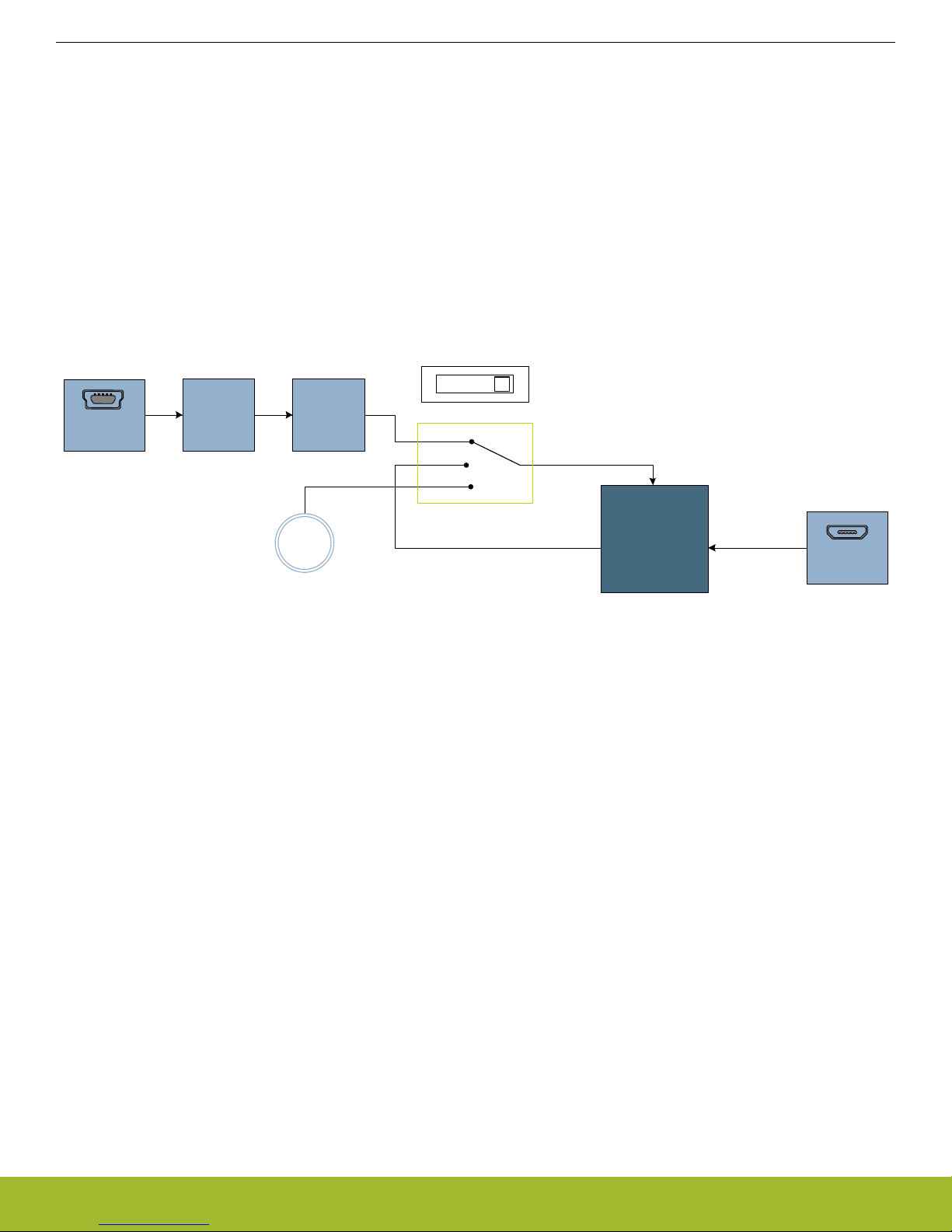
4.1 MCU Power Selection
The EZR32 Wonder Gecko MCU on the WSTK6222 is designed to be powered by three different sources:
• Through the on-board debugger.
• Through the EZR32's own USB regulator.
• By a 3V Battery.
Selecting the power source is done with the slide switch in the lower left corner of the board. Figure Figure 4.1 WSTK6222 Power
Switch on page 4 shows how the different power sources can be selected with the slide switch.
Figure 4.1. WSTK6222 Power Switch
With the switch in the DBG position, an on-board low noise LDO with a fixed output voltage of 3.3V is used to power the MCU. This
LDO is again powered from the "J-Link" USB cable. The Advanced Energy Monitor is now also connected in series, allowing accurate
high speed current measurements and energy debugging/profiling.
With the switch in the USB position, the integrated linear regulator in the EZR32 Wonder Gecko MCU is used to power the rest of the
chip as well as the USB PHY. This allows a USB device application where the MCU acts as a bus powered device.
Finally, with the switch in the BAT position, a 20mm coin cell battery in the CR2032 socket can be used to power the device.
Note:
The Advanced Energy Monitor can only measure the current consumption of the EZR32 when the power selection switch is in the DBG
position.
4.2 Board Controller Power
The Board Controller is responsible for important features such as the debugger and the Advanced Energy Monitor, and is powered
exclusively through the USB port in the top left corner of the board. This part of the kit resides on a separate power domain, so a different power source can be selected for the MCU while retaining debugging functionality. This power domain is also isolated to prevent
current leakage from the MCU power domain when power to the Board Controller is removed.
4.3 Backup Power Domain
The kit contains a backup capacitor that can be used together with the EZR32 Wonder Gecko's backup power domain. In this case, all
other power sources are removed from the kit, and only a small part of the EZR32 runs off the capacitor. It is also possible to enter
backup mode while the Board Controller is powered by selecting either BAT or USB with no battery in the socket or USB cable in the
connector.
silabs.com | Smart. Connected. Energy-friendly. Rev. 1.2 | 4
Page 8

EZR32WG 915MHz Wireless Starter Kit
Power Supply and Reset
4.4 MCU Reset
The EZR32 MCU can be reset by a few different sources:
• A user pressing the RESET button.
• The on-board debugger pulling the #RESET pin low.
• An external debugger pulling the #RESET pin low.
4.5 Board Controller Reset
The Board Controller can be reset by removing and re-inserting the J-Link USB cable. Removing the Board Controller USB cable will
not reset the EZR32, but whenever the Board Controller is powered up again, it will issue a RESET to the EZR32 through the on-board
debugger.
silabs.com | Smart. Connected. Energy-friendly. Rev. 1.2 | 5
Page 9
EZR32WG 915MHz Wireless Starter Kit
Peripherals
5. Peripherals
The starter kit has a set of peripherals that showcase some of the features of the EZR32 Wonder Gecko Wireless Microcontroller.
Be aware that most EZR32 I/O routed to peripherals are also routed to the breakout pads. This must be taken into consideration when
using the breakout pads for your application.
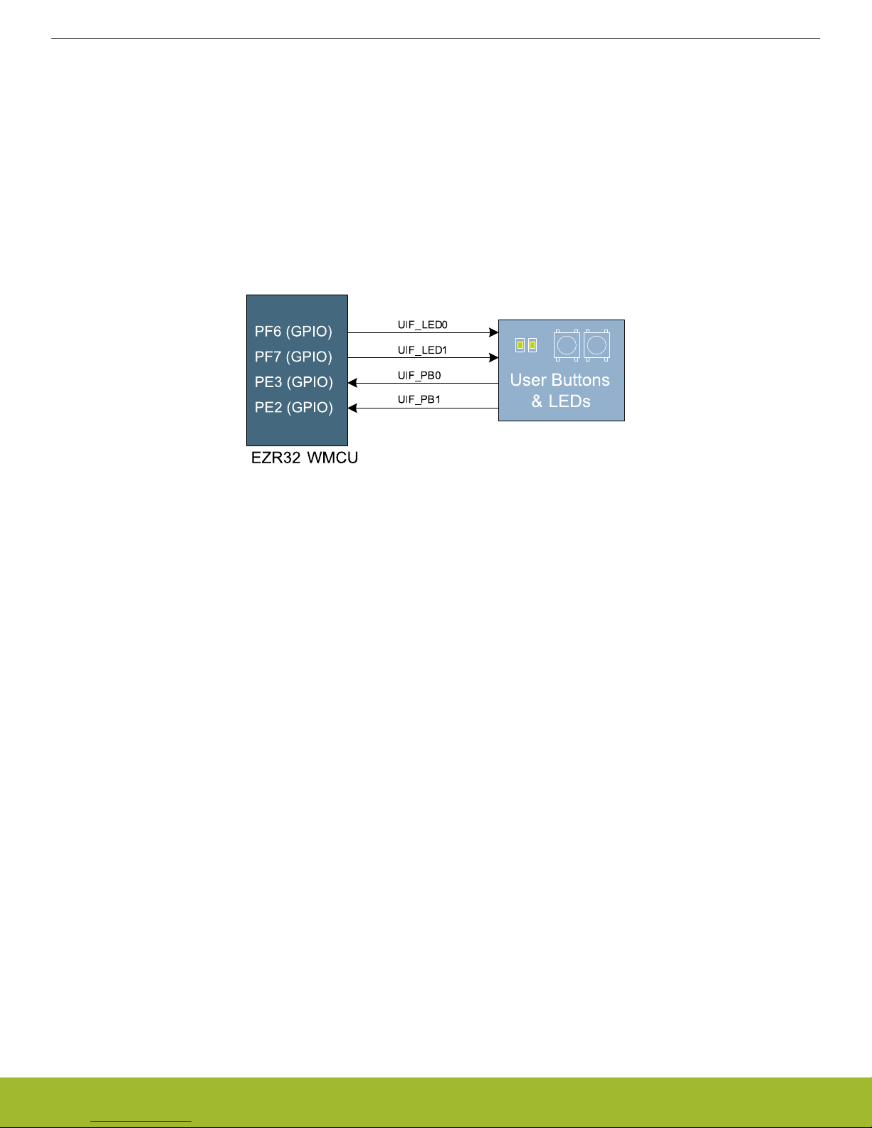
5.1 Push Buttons and LEDs
The kit has two user push buttons marked PB0 and PB1. They are connected to the EZR32, and are debounced by RC filters with a
time constant of 1ms. The buttons are connected to pins PC8 and PC9.
In addition to the two push buttons, the kit also features two yellow LEDs marked LED0 and LED1, that are controlled by GPIO pins on
the EZR32. The LEDs are connected to pins PC10 and PC11 in an active-high configuration.
Figure 5.1. Buttons/LEDs
silabs.com | Smart. Connected. Energy-friendly. Rev. 1.2 | 6
Page 10

EZR32WG 915MHz Wireless Starter Kit
Peripherals
5.2 Memory LCD-TFT Display
A 1.28-inch SHARP Memory LCD-TFT has been added to the board to enable interactive applications to be developed. The display has
a high resolution of 128 by 128 pixels, and consumes very little power. It is a reflective monochrome display, so each pixel can only be
light or dark, and no backlight is needed in normal daylight conditions.
The display interface consists of an SPI-compatible serial interface and some extra control signals. Data is sent to the display one line
(128 bits) at a time.
The Memory LCD-TFT display is shared with the kit Board Controller, allowing the Board Controller application to display useful information when the user application is not using the display. The user application always controls ownership of the display with
EFM_DISP_SELECT (PA8):
• 0: The Board Controller has control of the display
• 1: The user application (EZR32) has control of the display
EFM_DISP_PWR (PA10) enables power to the display, and must be set high in order to use the display. Data is clocked in on
EFM_DISP_MOSI (PD7) when EFM_DISP_CS (PE11) is high, and the clock is sent on EFM_DISP_SCLK (PC15). The maximum supported clock speed is 1.1 MHz.
EFM_DISP_COM (PE10) is the "COM Inversion" line. It must be pulsed periodically to prevent static build-up in the display itself.
Please refer to the display application information for details on driving the display:
http://www.sharpmemorylcd.com/1-28-inch-memory-lcd.html
5.3 Backup Domain Capacitor
A small super capacitor is provided to evaluate the EZR32 Wonder Gecko MCU's backup power domain. The capacitor has a nominal
value of 33 mF, and is connected with a 100 ohm series resistor to the BU_VIN pin of the EZR32.
Because of the extremely low power consumption of the EZR32 in backup mode (400nA), the capacitor can power a clock application
using the low frequency crystal oscillator (LFXO) for more than 8 hours.
The series resistor allows measuring of the current drawn from the capacitor into the EZR32 device, by simply using a multimeter to
measure the voltage across it. Please refer to the schematic and assembly drawings to locate the series resistor.
silabs.com | Smart. Connected. Energy-friendly. Rev. 1.2 | 7
Figure 5.2. 128x128 pixel Memory LCD
Page 11

EZR32WG 915MHz Wireless Starter Kit
Peripherals
5.4 USB Micro-B Connector
The BRD4503B WSTK Radio Board is equipped with a USB Micro-B connector that is connected directly to the EZR32. The Radio
Board supports operation in USB Device mode only, even if the target radio also supports USB Host mode. Figure 5.3 Radio Board
USB Connector on page 8 shows how the USB lines are connected to the EZR32.
Figure 5.3. Radio Board USB Connector
silabs.com | Smart. Connected. Energy-friendly. Rev. 1.2 | 8
Page 12

SENSOR_ENABLE
0: I2C lines are isolated, sensor is not powered
1: Sensor is powered and connected
PD7 (I2C0_SCL#0)
PD6 (I2C0_SDA#0)
PF8 (GPIO)
SENSOR_I2C_SDA
SENSOR_I2C_SCL
VMCU
VDD
SCL
SDA
Temperature
& Humidity
Sensor
EZR32WG 915MHz Wireless Starter Kit
Peripherals
5.5 Si7021 Relative Humidity and Temperature Sensor
The Si7021 I2C relative humidity and temperature sensor is a monolithic CMOS IC integrating humidity and temperature sensor elements, an analog-to-digital converter, signal processing, calibration data, and an I2C Interface. The patented use of industry-standard,
low-K polymeric dielectrics for sensing humidity enables the construction of low-power, monolithic CMOS Sensor ICs with low drift and
hysteresis, and excellent long term stability.
The humidity and temperature sensors are factory-calibrated and the calibration data is stored in the on-chip non-volatile memory. This
ensures that the sensors are fully interchangeable, with no recalibration or software changes required.
The Si7021 is available in a 3x3 mm DFN package and is reflow solderable. It can be used as a hardware- and software-compatible
drop-in upgrade for existing RH/ temperature sensors in 3x3 mm DFN-6 packages, featuring precision sensing over a wider range and
lower power consumption. The optional factory-installed cover offers a low profile, convenient means of protecting the sensor during
assembly (e.g., reflow soldering) and throughout the life of the product, excluding liquids (hydrophobic/oleophobic) and particulates.
The Si7021 offers an accurate, low-power, factory-calibrated digital solution ideal for measuring humidity, dew-point, and temperature,
in applications ranging from HVAC/R and asset tracking to industrial and consumer platforms.
The I2C bus used for the Si7021 is shared with the Expansion Header. The temperature sensor is normally isolated from the I2C line.
To use the sensor, PF8 must be set high. When enabled, the sensor's current consumption is included in the AEM measurements.
Figure 5.4. Si7021 Relative Humidity and Temperature Sensor
silabs.com | Smart. Connected. Energy-friendly. Rev. 1.2 | 9
Page 13

EZR32WG 915MHz Wireless Starter Kit
Advanced Energy Monitor
6. Advanced Energy Monitor
6.1 Introduction
Any embedded developer seeking to make his embedded code spend as little energy as the underlying architecture supports, needs
tools to easily and quickly discover inefficiencies in the running application.
This is what the Simplicity Energy Profiler is designed to do. It will in real-time graph and log current as a function of time while correlating this to the actual target application code running on the EZR32. There are multiple features in the profiler software that allows for
easy analysis, such as markers and statistics on selected regions of the current graph or aggregate energy usage by different parts of
the application.
6.2 Advanced Energy Monitor - Theory of operation
The AEM circuitry on the board is capable of measuring current signals in the range of 0.1uA to 150mA, which is close to 123dBs of
dynamic range. It can do this while stil maintaining approximately 10kHz of current signal bandwidth. This is accomplished through a
combination of a highly capable current sense amplifier, multiple gain stages and signal processing within the kit's board controller before the current sense signal is read by a host computer for display and/or storage.
The current sense amplifier measures the voltage drop over a small series resistor, and the gain stage further amplifies this voltage with
two different gain settings to obtain two current ranges. The transition between these two ranges occurs around 250 µA.
The current signal is combined with the target MCU's Program Counter (PC) sampling by utilizing a feature of the ARM CoreSight debug architecture. The ITM (Instrumentation Trace Macrocell) block can be programmed to sample the MCU's PC at periodic intervals
( 50kHz ) and output these over SWO pin ARM devices. When these two data streams are fused and correlated with the running application's memory map, an accurate statistical profile can be built over time, that shows the energy profile of the running application in
real-time.
At kit power-up or on a power-cycle, and automatic AEM calibration is performed. This calibration compensates for any offset errors in
the current sense amplifiers.
silabs.com | Smart. Connected. Energy-friendly. Rev. 1.2 | 10
Figure 6.1. Advanced Energy Monitor
Page 14

EZR32WG 915MHz Wireless Starter Kit
Advanced Energy Monitor
6.3 AEM accuracy and performance
The Advanced Energy Monitor is capable of measuring currents in the range of 0.1 µA to95mA. For currents above 250 µA, the AEM is
accurate within 0.1 mA. When measuring currents below 250 µA, the accuracy increases to 1 µA. Even though the absolute accuracy is
1 µA in the sub 250 µA range, the AEM is able to detect changes in the current consumption as small as 100 nA.
The AEM current sampling rate is 10000 Hz.
Note: The AEM circuitry only works when the kit is powered and the power switch is in the AEM/DBG position.
6.4 Usage
The AEM (Advanced Energy Monitor) data is collected by the board controller and can be displayed by the Energy Profiler, available
through Simplicity Studio. By using the Energy Profiler, current consumption and voltage can be measured and linked to the actual
code running on the EZR32 in realtime.
silabs.com | Smart. Connected. Energy-friendly. Rev. 1.2 | 11
Page 15

EZR32WG 915MHz Wireless Starter Kit
Board Controller
7. Board Controller
The kit contains a board controller that is responsible for performing various board-level tasks, such as handling the debugger and the
Advanced Energy Monitor. An interface is provided between the EZR32 and the board controller in the form of a UART connection. The
connection is enabled by setting the VCOM_ENABLE (PA12) line high, and using the lines VCOM_TX (PB3) and VCOM_RX (PB4) for
communication.
Specific library functions have been provided in the kit Board Support Package that support various requests to be made to the board
controller, such as quering AEM voltage or current. To use these functions, the Board Support Package must be installed. See the to
find out more.
Note:
The board controller is only available when USB power is connected.
7.1 VCOM
When enabling virtual serial communication (VCOM), the board controller makes communication possible on the following interfaces:
• Virtual USB COM port using a CDC driver, provided that the kit is connected to a host computer.
• TCP/IP, by connecting to the Wireless Starter Kit on port 4901 using a telnet client.
• Expansion header when enabled by the board controller.
The VCOM functionality can operate in two different modes:
• Transparent mode allows the target to communicate using a regular serial driver. The board controller forwards the raw byte stream
to its interfaces.
• BSP-mode is initiated by a BSP call in the target application. This mode enables the target to use all BSP functionality, while having
access to VCOM over USB and Ethernet.
silabs.com | Smart. Connected. Energy-friendly. Rev. 1.2 | 12
Page 16

EZR32WG 915MHz Wireless Starter Kit
Board Support Package
8. Board Support Package
The Board Support Package (BSP) is a set of C source and header files that enables easy access to, and control over some board
specific features. Using the BSP is not required, and the EZR32 is fully usable without the BSP.
The BSP uses EZR32 peripheral USART2, Location 1 (TX pin PB3, RX pin PB4) on baudrate 115200-8-N-1 to communicate with the
board controller.
Note:
The BSP functionality is only available when the Starter Kit is USB-powered. Using these function calls with USB disconnected will give
unpredictable results.
8.1 Application Programming Interface
To use the BSP, include the Starter Kit header file, like this:
#include "bsp.h"
All functions in the BSP are prefixed with BSP_. Some functions to control the user LEDs might look like:
int BSP_LedClear (int ledNo)
Turn off a single LED.
int BSP_LedSet (int ledNo)
Turn on a single LED.
8.2 Example Applications
Under the kits/EZR32WG_WSTK6222/examples folder in your base Simplicity installation directory, you will find example programs using the BSP, with corresponding project/Makefiles for supported IDEs.
The examples folder also contains examples showing how to use the different peripherals on the WSTK6222.
8.3 How to include in your own applications
The easiest way to include the BSP in your application is to create it using the Simplicity IDE.
Alternatively to base your work on the example application that uses the BSP. The following items are recommended for correct configuration:
1. Make sure you define the correct part number (i.e. EZR32WG330F256R63G) as a preprocessor defined symbol
2. Make sure you define the correct part number (i.e. EZR32WG330F256R63G) for your project file
3. Add and include the EFM32_CMSIS-files (startup_efm32.s, system_efm32.c, core_cm3.c) to your project
4. Add and include all BSP package .c-files, with the bsp-prefix to your project
5. Configure include paths to point at the CMSIS/CM3/CoreSupport and CMSIS/CM3/DeviceSupport/EnergyMicro/EFM32 directories
6. Configure include paths to point to the kits/EZR32WG_WSTK6222/bsp directory
Make sure you call "BSP_Init()" early at startup, and you should be all set.
silabs.com | Smart. Connected. Energy-friendly. Rev. 1.2 | 13
Page 17

Simplicity
Connector
In/Out Debug
Header
GND
GND
5V
5V
P25
P24
P27
P26
P29
P28
P31
P30
P33
P32
P35
P34
P37
P36
P39
P38
P41
P40
P43
P42
P45
P44
GND
GND
NC
NC
Radio Board
Connectors
Expansion
Header
GND
GND
VMCU
VMCU
P1
P0
P3
P2
P5
P4
P7
P6
P9
P8
P11
P10
P13
P12
P15
P14
P17
P16
P19
P18
P21
P20
GND
GND
P23
P22
VRF
VRF
3V3
3V3
EZR32WG 915MHz Wireless Starter Kit
Connectors
9. Connectors
This chapter gives you an overview of the Wireless Starter Kit Mainboard connectivity. The placement of the connectors can be seen in
the figure below.
Figure 9.1. Connector layout
9.1 Radio Board breakout pads
Most of the EZR32's pins are routed out to "breakout pads" at the top and bottom edges of the Wireless Starter Kit Mainboard. A
2.54mm pitch pin header can be soldered on for easy access to the pins. The figure below shows you how the pins of the EZR32
Wonder Gecko Radio Board (BRD4503B (Rev. A00)) maps to the pins indicated on the breakout pads. To see the available functions
on each pin we refer you to the EZR32WG330F256R63G reference manual available in Simplicity Studio.
Figure 9.2. Radio board pin mapping on breakout pads.
silabs.com | Smart. Connected. Energy-friendly. Rev. 1.2 | 14
Page 18

1 2
4
8
6
10
3
5
9
12
13 14
11
15 16
17
18
2019
SWDIO / TMS
SWCLK / TCK
SWO / TDO
TDI
TRACECLK
TRACE_DATA[0]
TRACE_DATA[1]
TRACE_DATA[2]
TRACE_DATA[3]
#RESET
VTARGET
GND
GND
NC
Cable Detect
NC
NC
GND
GND
GND
EZR32WG 915MHz Wireless Starter Kit
Connectors
9.2 Debug Connector (DBG)
This connector is used for Debug In and Debug Out (see chapter on Debugging). The pinout is described in Table 9.1 Debug Connec-
tor Pinout on page 15.
Figure 9.3. Debug Connector
Note that the pin-out matches the pin-out of an ARM Cortex Debug+ETM connector, but these are not fully compatible as pin 7 is physically removed from the Cortex Debug+ETM connector.
Table 9.1. Debug Connector Pinout
Pin number(s) Function Note
1 VTARGET Target voltage on the debugged application.
2 TMS/SDWIO JTAG TMS or Serial Wire Data I/O
4 TCK/SWCLK JTAG TCK or Serial Wire clock
6 TDO/SWO JTAG TDO or Serial Wire Output
8 TDI JTAG data in
10 #RESET Target MCU reset
12 TRACECLK ETM Trace Clock
14 TRACEDATA[0] ETM Trace Data 0
16 TRACEDATA[1] ETM Trace Data 1
18 TRACEDATA[2] ETM Trace Data 2
20 TRACEDATA[3] ETM Trace Data 3
9 Cable detect This signal must be pulled to ground by the external debugger or application for ca-
ble insertion detection.
11, 13 NC Not connected
3, 5, 15, 17, 19 GND
Note: The Wireless Starter Kit Mainboard does not have an onboard trace emulator. To have trace functionality an external debugger
with such functionality can be connected with Debug In.
Note: Although the Debug Connector can support JTAG debugging of external targets, the EZR32-series of devices do not support
JTAG.
silabs.com | Smart. Connected. Energy-friendly. Rev. 1.2 | 15
Page 19

3V3 AEM measured voltage
1
33V3
5
5V
15
GND
13
GND
11
GND
9
GND
7
GND
17
Board ID SCL
19
Board ID SDA
2
Virtual COM TX / MOSI
4 Virtual COM RX / MISO
6 Virtual COM CTS / SCLK
8
Virtual COM RTS / CS
10
Packet Trace 0 Sync
12
Packet Trace 0 Data
14
Packet Trace 0 Clock
16
Packet Trace 1 Sync
18
Packet Trace 1 Data
20
Packet Trace 1 Clock
EZR32WG 915MHz Wireless Starter Kit
Connectors
9.3 Simplicity Connector
The Simpicity Connector featured on the Wireless Starter Kit Mainboard enables advanced debugging features such as the AEM, the
Virtual COM port and the Packet Trace Interface to be used towards an external target. The pinout is illustrated in the figure below.
Figure 9.4. Simplicity Header pinout.
Current drawn from the VMCU voltage pin is included in the AEM measurements, while the 3V3 and 5V voltage pins are not. To monitor the current consumption of an external target with the AEM, unplug the WSTK Radio Board from the WSTK Mainboard to avoid that
the Radio Board current consumption is added to the measurements.
Table 9.2. Simplicity Header pin descriptions
Pin number(s) Function Note
1 VMCU 3.3 V power rail, monitored by the AEM
3 3V3 3.3 V power rail
5 5V 5 V power rail
2 VCOM_TX_MOSI Virtual COM Tx/MOSI
4 VCOM_RX_MISO Virtual COM Rx/MISO
6 VCOM_CTS_#SCLK Virtual COM CTS/SCLK
8 VCOM_#RTS_#CS Virtual COM RTS/CS
10 PTI0_SYNC Packet Trace 0 Sync
12 PTI0_DATA Packet Trace 0 Data
14 PTI0_CLK Packet Trace 0 Clock
16 PTI1_SYNC Packet Trace 1 Sync
18 PTI1_DATA Packet Trace 1 Data
20 PTI1_CLK Packet Trace 1 Clock
17 EXT_ID_SCL Board ID SCL
19 EXT_ID_SDA Board ID SDA
7, 9, 11, 13, 15 GND
silabs.com | Smart. Connected. Energy-friendly. Rev. 1.2 | 16
Page 20

EZR32WG 915MHz Wireless Starter Kit
Connectors
9.4 Expansion header
On the right hand side of the board an angled 20 pin expansion header is provided to allow connection of peripherals or plugin boards.
The connecter contains a number of I/O pins that can be used with most of the EZR32 Wonder Gecko's features. Additionally, the
VMCU, 3V3 and 5V power rails are also exported.
Figure shows the pin assignment of the expansion header. With a few exceptions, most of the expansion header pins are the same as
those on other EFM starter kits.
Some of the chip peripheral functions that are available on the Expansion Header are listed in table Table 9.3 Some peripheral func-
tions available on Expansion Header on page 17.
Figure 9.5. Expansion Header
Table 9.3. Some peripheral functions available on Expansion Header
Peripheral Peripheral pin MCU Pin EXP Header pin number
USART/SPI USART1_TX PD0 4
USART1_RX PD1 6
USART1_CLK PD2 8
USART1_CS PD3 10
I2C
I2C1_SDA PC4 7
I2C1_SCL PC5 9
Low Energy UART LEUART0_TX PD4 12
LEUART0_RX PD5 14
Analog to Digital Converter ADC0_CH0 PD0 4
ADC0_CH1 PD1 6
ADC0_CH2 PD2 8
silabs.com | Smart. Connected. Energy-friendly. Rev. 1.2 | 17
ADC0_CH3 PD3 10
ADC0_CH4 PD4 12
ADC0_CH5 PD5 14
ADC0_CH6 PD6 16
ADC0_CH7 PD7 17
Page 21

EZR32WG 915MHz Wireless Starter Kit
Peripheral Peripheral pin MCU Pin EXP Header pin number
Digital to Analog Converter DAC0_CH0 PB11 11
DAC0_CH1 PB12 13
Analog Comparator ACMP0_CH0 PC0 3
ACMP0_CH3 PC3 5
ACMP0_CH4 PC4 7
ACMP0_CH5 PC5 9
ACMP0_CH6 PC6 15
ACMP0_O PD6 16
ACMP1_O PD7 17
Operational Amplifier OPAMP_N0 PC5 9
OPAMP_P0 PC4 7
OPAMP_OUT0 PB11 11
OPAMP_N1 PD7 17
Connectors
OPAMP_P1 PD6 16
OPAMP_OUT1 PB12 13
OPAMP_N2 PD3 10
OPAMP_P2 PD4 12
OPAMP_OUT2 PD5, PD0 14, 4
Timer Compare/Capture TIMER0_CC0 PD1 6
TIMER0_CC1 PD2 8
TIMER0_CC2 PD3 10
TIMER1_CC0 PD6 16
TIMER1_CC1 PD7 17
TIMER1_CC2 PB11 11
Low Energy Timer LETIM0_OUT0 PD6, PB11, PC4 16, 11, 7
LETIM0_OUT1 PD7, PB12, PC5 17, 13, 9
Low Energy Sensor Interface (LESENSE) LES_CH0 PC0 3
LES_CH3 PC3 5
LES_CH4 PC4 7
silabs.com | Smart. Connected. Energy-friendly. Rev. 1.2 | 18
LES_CH5 PC5 9
LES_CH6 PC6 15
LES_ALTEX0 PD6 16
LES_ALTEX1 PD7 17
Page 22

EZR32WG 915MHz Wireless Starter Kit
Connectors
Peripheral Peripheral pin MCU Pin EXP Header pin number
Pulse Counter PCNT0_S0IN PD6 16
PCNT0_S1IN PD7 17
PCNT1_S0IN PC4 7
PCNT1_S1IN PC5 9
PCNT2_S0IN PD0 4
PCNT2_S1IN PD1 6
Peripheral Reflex System (PRS) PRS_CH2 PC0 3
Note:
Please note that this table only sums up some of the alternate functions available on the expansion header. Consult the
EZR32WG330F256R63G datasheet for a complete list of alternate functions.
silabs.com | Smart. Connected. Energy-friendly. Rev. 1.2 | 19
Page 23

10. Integrated Development Environments
EZR32WG 915MHz Wireless Starter Kit
Integrated Development Environments
Simplicity Studio includes various examples in source form to use with the Starter Kit. To run these examples:
1. Provide power to the board by connecting the DBG USB connector to the PC using the provided USB cable.
2. Move the switch to the AEM position.
3. Click the [Refresh detected hardware] button and select the WSTK6222 kit under [Detected Hardware].
4. Click the [Software Examples] tile under [Software and Kits].
5. In the wizard, select the WSTK6222 kit and click [Next].
6. Select the desired example or demo from the list and click [Next].
7. Click [Finish].
8. Click the [Debug] button in the IDE to build and download the code to the hardware.
9. Follow the instructions at the top of the main example file to set up the hardware as needed.
10. Click the [Resume] button to start running the example.
10.1 IAR Embedded Workbench for ARM
An evaluation version of IAR Embedded Workbench for ARM is included on a CD in the WSTK6222 package. Check the quick start
guide for where to find updates, and IAR's own documentation on how to use it. You will find the IAR project file in the
iar
subfolder of each project
silabs.com | Smart. Connected. Energy-friendly. Rev. 1.2 | 20
Figure 10.1. Simplicity Studio
Page 24

EZR32WG 915MHz Wireless Starter Kit
Integrated Development Environments
10.2 Atollic TrueSTUDIO for ARM
See the quick start guide for download details for Atollic TrueSTUDIO for ARM. You will find TrueStudio project files in the
atollic
subfolder of each project.
10.3 Rowley Associates - CrossWorks for ARM
See the quick start guide for download details for CrossWorks for ARM. You will find CrossWorks project files in the
rowley
subfolder of each project.
10.4 Keil - MDK-ARM
See the quick start guide for download details for evaluation versions of Keil MDK-ARM. The
arm
subfolder in each project contains project files for MDK-ARM. Please see the MDK-ARM documentation for usage details.
silabs.com | Smart. Connected. Energy-friendly. Rev. 1.2 | 21
Page 25

EZR32WG 915MHz Wireless Starter Kit
Kit Manager and Upgrades
11. Kit Manager and Upgrades
The Kit Manager is a program that comes with Simplicity Studio. It can perform various kit and EZR32 specific tasks.
11.1 Kit Manager Operation
This utility gives the ability to program the EZR32, upgrade the kit, lock and unlock devices and more. Some of the features will only
work with Energy Micro kits, while other will work with a generic J-Link debugger connected.
11.2 Firmware Upgrades
Upgrading the kit firmware is done through Simplicity Studio. Simplicity Studio will automatically check for new updates on startup.
You can also use the Kit Manager for manual upgrades. Click the [Browse] button in the [Update Kit] section to select the correct file
ending in ".emz". Then, click the [Install Package] button.
silabs.com | Smart. Connected. Energy-friendly. Rev. 1.2 | 22
Figure 11.1. Kit Manager
Page 26

EZR32WG 915MHz Wireless Starter Kit
Schematics, Assembly Drawings and BOM
12. Schematics, Assembly Drawings and BOM
The schematics, assembly drawings and bill of materials (BOM) for the EZR32WG 915MHz Wireless Starter Kit board are available
through Simplicity Studio when the kit documentation package has been installed.
silabs.com | Smart. Connected. Energy-friendly. Rev. 1.2 | 23
Page 27

13. Kit Revision History and Errata
13.1 Revision History
The kit revision can be found printed on the box label of the kit, as outlined in the figure below.
Figure 13.1. Revision info
EZR32WG 915MHz Wireless Starter Kit
Kit Revision History and Errata
Table 13.1. Kit Revision History
Kit Revision Released Description
A01 02.02.2015 Initial kit release.
13.2 Errata
Table 13.2. Kit Errata
Kit Revision Problem Description
A00 - A01 Radio board errata This kit revision includes a radio board with known errata. See BRD4503B user
guide for details.
silabs.com | Smart. Connected. Energy-friendly. Rev. 1.2 | 24
Page 28

14. Document Revision History
Table 14.1. Document Revision History
Revision Number Effective Date Change Description
1.2 19.03.2015 Kit Errata added.
1.1 23.02.2015 Minor text revision.
1.00 19.02.2015 Major updates.
0.10 23.12.2014 Initial document version.
EZR32WG 915MHz Wireless Starter Kit
Document Revision History
silabs.com | Smart. Connected. Energy-friendly. Rev. 1.2 | 25
Page 29

Simpilcity Studio
One-click access to MCU tools,
documentation, software, source
code libraries & more. Available
for Windows, Mac and Linux!
www.silabs.com/simplicity
MCU Portfolio
www.silabs.com/mcu
Disclaimer
Silicon Laboratories intends to provide customers with the latest, accurate, and in-depth documentation of all peripherals and modules available for system and software implementers
using or intending to use the Silicon Laboratories products. Characterization data, available modules and peripherals, memory sizes and memory addresses refer to each specific
device, and "Typical" parameters provided can and do vary in different applications. Application examples described herein are for illustrative purposes only. Silicon Laboratories
reserves the right to make changes without further notice and limitation to product information, specifications, and descriptions herein, and does not give warranties as to the accuracy
or completeness of the included information. Silicon Laboratories shall have no liability for the consequences of use of the information supplied herein. This document does not imply
or express copyright licenses granted hereunder to design or fabricate any integrated circuits. The products must not be used within any Life Support System without the specific
written consent of Silicon Laboratories. A "Life Support System" is any product or system intended to support or sustain life and/or health, which, if it fails, can be reasonably expected
to result in significant personal injury or death. Silicon Laboratories products are generally not intended for military applications. Silicon Laboratories products shall under no
circumstances be used in weapons of mass destruction including (but not limited to) nuclear, biological or chemical weapons, or missiles capable of delivering such weapons.
Trademark Information
Silicon Laboratories Inc., Silicon Laboratories, Silicon Labs, SiLabs and the Silicon Labs logo, CMEMS®, EFM, EFM32, EFR, Energy Micro, Energy Micro logo and combinations
thereof, "the world’s most energy friendly microcontrollers", Ember®, EZLink®, EZMac®, EZRadio®, EZRadioPRO®, DSPLL®, ISOmodem ®, Precision32®, ProSLIC®, SiPHY®,
USBXpress® and others are trademarks or registered trademarks of Silicon Laboratories Inc. ARM, CORTEX, Cortex-M3 and THUMB are trademarks or registered trademarks of
ARM Holdings. Keil is a registered trademark of ARM Limited. All other products or brand names mentioned herein are trademarks of their respective holders.
Silicon Laboratories Inc.
400 West Cesar Chavez
Austin, TX 78701
USA
SW/HW
www.silabs.com/simplicity
Quality
www.silabs.com/quality
Support and Community
community.silabs.com
http://www.silabs.com
 Loading...