

Page 1
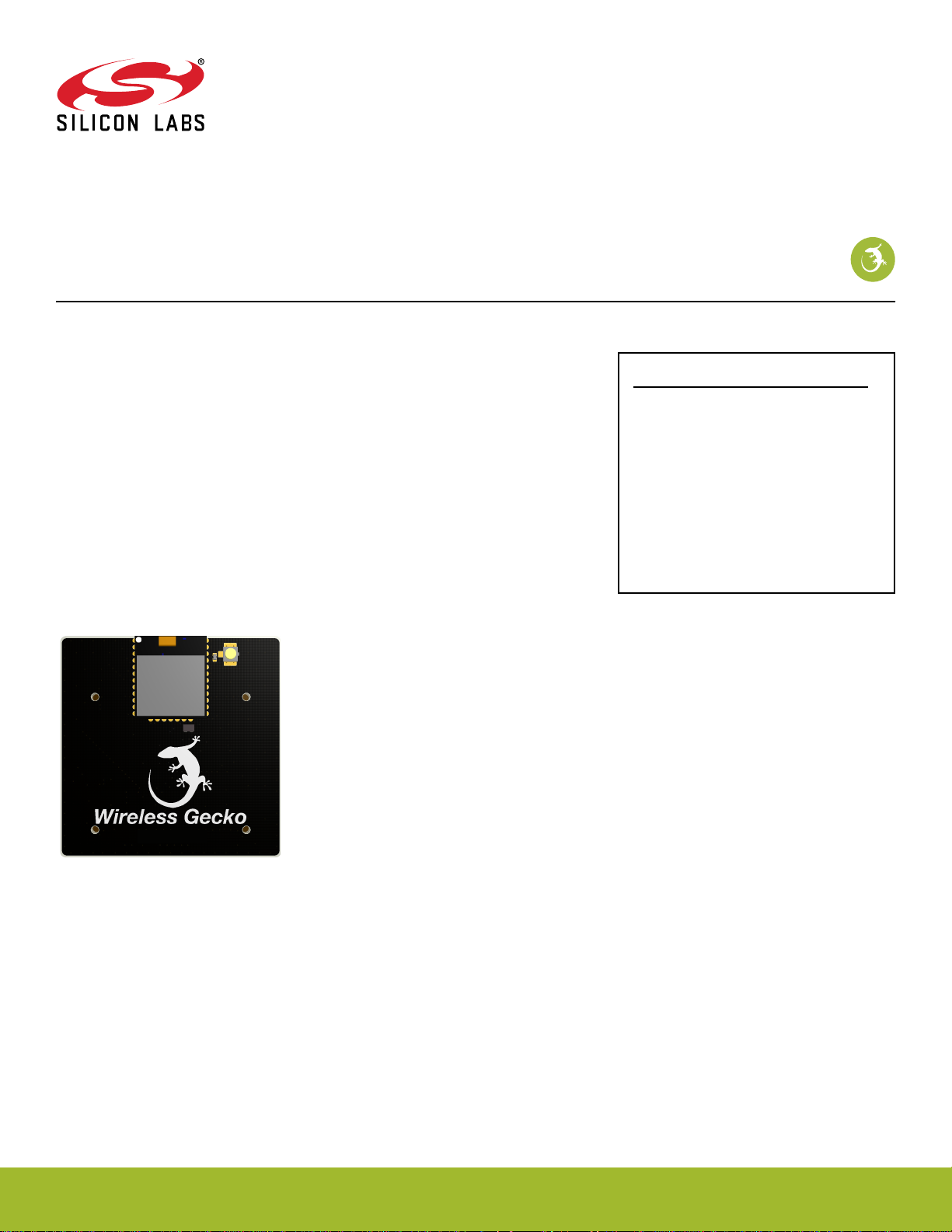
MGM210PB22 Module Radio Board
xGM210PB22
BRD4308D Reference Manual
The BRD4308D Wireless Gecko Radio Board contains a Wireless Gecko module, which
integrates Silicon Labs' EFR32MG22 Wireless Gecko SoC into a small form factor module. The fully certified module contains all components (a high-performance transceiver,
an energy efficient 32-bit MCU, crystals, RF passives, and antenna) required for a sys-
tem-level implementation of Zigbee®, Thread® Bluetooth® and multi-protocol (ZigBee +
Bluetooth) networks operating in the 2.4 GHz band with 10 dBm output power.
The BRD4308D Wireless Gecko Radio Board plugs into the Wireless Starter Kit Mainboard, which is included with the Wireless Gecko Starter Kit and gives access to display, buttons, and additional features from expansion boards. With the supporting Simplicity Studio suite of tools, developers can take advantage of graphical wireless application development, mesh networking debug and packet trace, and visual energy profiling and optimization.
This document contains a brief introduction and description of the BRD4308D Radio
Board features, focusing on the RF performance.
RADIO BOARD FEATURES
• Wireless Module: MGM210PB22JIA2
•
CPU core: ARM Cortex®-M33
• Flash/RAM memory: 1024 kB/96 kB
• Secure Vault
• Operation frequency: 2.4 GHz
• Transmit power: 10 dBm
• Integrated chip antenna, RF matching
network, crystals, and decoupling
• UFL connector for conducted tests
silabs.com | Building a more connected world. Rev. 1.0
Page 2

Table of Contents
1. Introduction ................................3
2. Radio Board Connector ...........................4
2.1 Introduction ...............................4
2.2 Radio Board Connector Pin Associations .....................4
3. Radio Board Block Summary .........................5
3.1 Introduction ...............................5
3.2 Radio Board Block Diagram .........................5
3.3 Radio Board Block Description ........................5
3.3.1 Wireless Module ............................5
3.3.2 Radio Board Connectors .........................5
3.3.3 LF Crystal Oscillator (LFXO) ........................5
3.3.5 Serial EEPROM ............................5
4. Mechanical Details .............................6
5. EMC Compliance ..............................7
5.1 Introduction ...............................7
5.2 EMC Regulations for 2.4 GHz .........................7
5.2.1 ETSI EN 300-328 Emission Limits for the 2400-2483.5 MHz Band ...........7
5.2.2 FCC15.247 Emission Limits for the 2400-2483.5 MHz Band .............7
5.2.3 Applied Emission Limits for the 2.4 GHz Band ..................7
6. RF Performance ..............................8
6.1 Conducted Power Measurements .......................8
6.1.1 Conducted Measurements in the 2.4 GHz Band .................8
6.2 Radiated Power Measurements ........................9
6.2.1 Radiated Measurements in the 2.4 GHz Band ..................9
6.2.2 Antenna Pattern Measurements.......................9
7. EMC Compliance Recommendations ......................11
7.1 Recommendations for 2.4 GHz ETSI EN 300-328 Compliance ..............11
7.2 Recommendations for 2.4 GHz FCC 15.247 Compliance ................11
8. Board Revision History .......................... 12
9. Errata ................................. 13
10. Document Revision History ........................ 14
silabs.com
| Building a more connected world. Rev. 1.0 | 2
Page 3

BRD4308D Reference Manual
Introduction
1. Introduction
The BRD4308D Radio Boards provide a development platform (together with the Wireless Starter Kit Mainboard) for the Silicon Labs
Wireless Gecko modules.
By carrying the MGM210PB22 module, the BRD4308D Radio Board is designed to operate in the 2400-2483.5 MHz with the maximum
of 10 dBm output power.
To develop and/or evaluate the MGM210PB22 module, the BRD4308D Radio Board can be connected to the Wireless Starter Kit Mainboard to get access to display, buttons, and additional features from expansion boards (EXP boards).
silabs.com | Building a more connected world. Rev. 1.0 | 3
Page 4
GND
F9 / PC01 / VCOM_RTS
3v3
NC / P36
P200
Upper Row
NC / P38
NC / P40
DBG_TDO_SWO / PA03 / P42
NC / P44
DBG_TMS_SWDIO / PA02 / F0
DISP_ENABLE / PD04 / F14
UIF_BUTTON0 / UIF_LED0 / PB00 / F12
UIF_BUTTON0 / UIF_LED0 / PB00 / F10
VCOM_CTS / PD02 / F8
DBG_RESET / #RESET / F4
DBG_TDO_SWO / PA03 / F2
DISP_MOSI* / PC00* / F16
VCOM_TX / PA05 / F6
PTI_DATA / PC04 / F20
DISP_EXTCOMIN / PA00 / F18
USB_VBUS
5V
Board ID SCL
GND
Board ID SDA
USB_VREG
F7 / PA06 / VCOM_RX
F5 / PD03 / SENSOR_ENABLE
F3 / PA04 / DBG_TDI
F1 / PA01 / DBG_TCK_SWCLK
P45 / NC
P43 / NC
P41 / PA04 / DBG_TDI
P39 / NC
P37 / NC
F11 / PB01 / UIF_BUTTON1 / UIF_LED1
F13 / PB01 / UIF_BUTTON1 / UIF_LED1
F15 / PC02** / DISP_SCLK**
F17 / PC03 / DISP_SCS
F19 / PC05 / PTI_SYNC
F21 / NC
GND
VMCU_IN
DISP_MOSI* / PC00* / P0
P201
Lower Row
DISP_SCLK** / PC02** / P2
UIF_BUTTON0 / UIF_LED0 / PB00 / P4
UIF_BUTTON1 / UIF_LED1 / PB01 / P6
GND
VRF_IN
P35 / PC05 / PTI_SYNC
P7 / PC03 / DISP_SCS
P5 / PC02** / DISP_SCLK**
P3 / PC01 / VCOM_RTS
P1 / PC00* / DISP_MOSI*
P33 / PC04 / PTI_DATA
P31 / NC
P29 / PD04 / DISP_ENABLE
P27 / PD03 / SENSOR_ENABLE
P25 / PD02 / VCOM_CTS
P23 / NC
P21 / NC
P19 / NC
P17 / NC
P15 / NC
P13 / PC02** / DISP_SCLK**
P11 / PA06 / VCOM_RX
P9 / PA05 / VCOM_TX
NC / P34
NC / P32
NC / P30
NC / P28
NC / P26
NC / P24
DBG_TDI / PA04 / P22
DBG_TDO_SWO / PA03 / P20
DBG_TMS_SWDIO / PA02 / P18
DBG_TCK_SWCLK / PA01 / P16
DISP_EXTCOMIN / PA00 / P14
DISP_MOSI* / PC00* / P12
NC / P10
NC / P8
** Mutually exclusive connections. Default: PC00 to P1 and F16
** Mutually exclusive connections. Default: PC02 to P5 and F15.
BRD4308D Reference Manual
Radio Board Connector
2. Radio Board Connector
2.1 Introduction
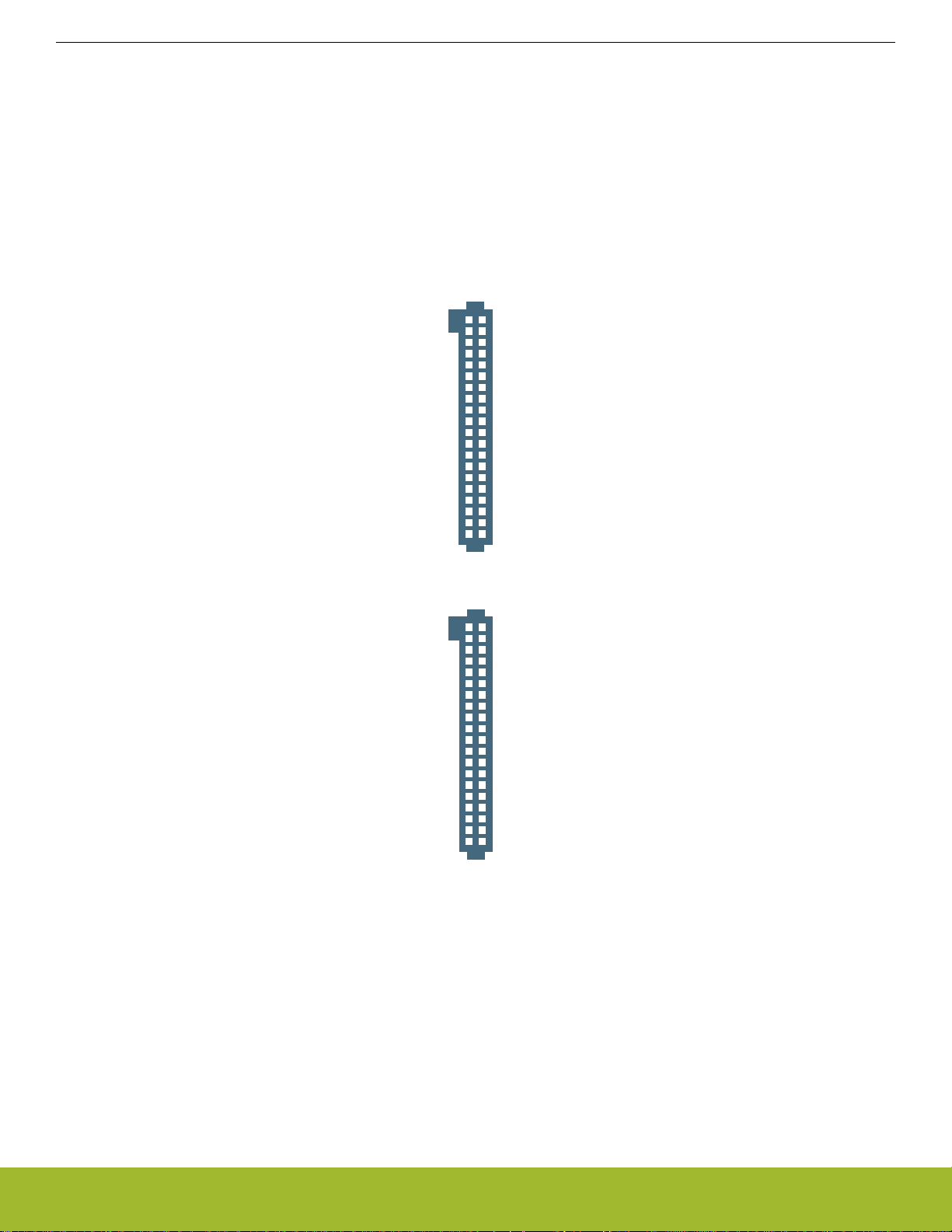
The board-to-board connector scheme allows access to all MGM210PB22 GPIO pins as well as the RESETn signal. For more information on the functions of the available pins, see the MGM210PB22 data sheet.
2.2 Radio Board Connector Pin Associations
The figure below shows the mapping between the connector and the MGM210PB22 pins and their function on the Wireless Starter Kit
Mainboard.
silabs.com | Building a more connected world. Rev. 1.0 | 4
Figure 2.1. BRD4308D Radio Board Connector Pin Mapping
Page 5
3. Radio Board Block Summary
2.4 GHz RF
UFL
Connector
Radio
Board
Connectors
I2C
24AA0024
Serial EEPROM
GPIO
UART
Debug
Packet Trace
AEM
I2C
SPI
EFR32
xGM210P
Module
Chip
Antenna
RF In/Out
LF
Crystal
32.768k
3.1 Introduction
This section introduces the blocks of the BRD4308D Radio Board.
3.2 Radio Board Block Diagram
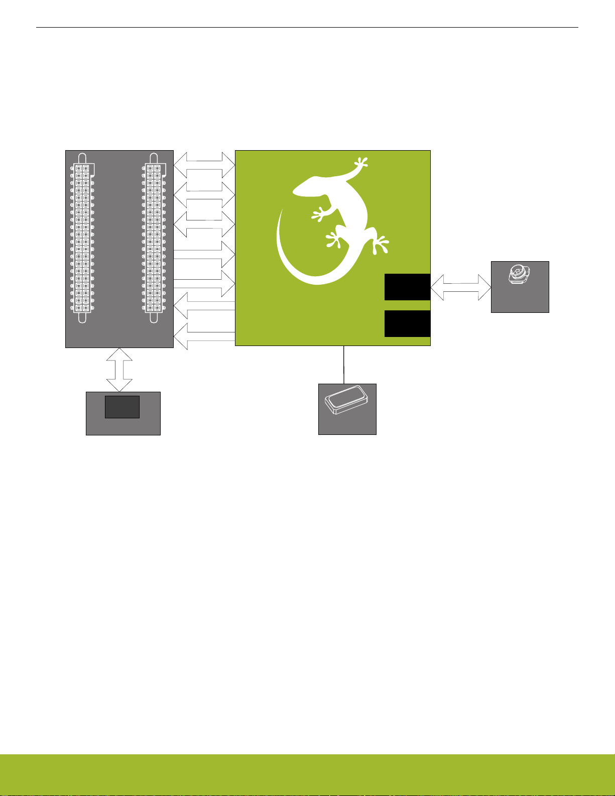
The block diagram of the BRD4308D Radio Board is shown in the figure below.
BRD4308D Reference Manual
Radio Board Block Summary
Figure 3.1. BRD4308D Block Diagram
3.3 Radio Board Block Description
3.3.1 Wireless Module
The MGM210PB22JIA2 module incorporated on the BRD4308D Wireless Gecko Radio Board features a 32-bit Cortex®-M33 core,
1024 kB of flash memory, 96 kB of RAM, crystals, and a 2.4 GHz band transceiver with RF passives and integrated antenna output
power up to 10 dBm. For additional information on the MGM210PB22JIA2, refer to the MGM210P data sheet.
3.3.2 Radio Board Connectors
Two dual-row, 0.05” pitch polarized connectors make up the BRD4308D Radio Board interface to the Wireless Starter Kit Mainboard.
For more information on the pin mapping between the MGM210PB22JIA2 and the Radio Board Connector, refer to section 2.2 Radio
Board Connector Pin Associations.
3.3.3 LF Crystal Oscillator (LFXO)
The BRD4308D Radio Board has a crystal mounted. For details regarding the crystal configuration, refer to application note AN0016.2:
Oscillator Design Considerations.
3.3.5 Serial EEPROM
The BRD4308D Radio Board is equipped with a serial I2C EEPROM for board identification and to store additional board-related information.
silabs.com | Building a more connected world. Rev. 1.0 | 5
Page 6
4. Mechanical Details
40 mm
32.5 mm
20 mm
40 mm
xGM210P
Module
LFXTAL
UFL
Connector
20 mm
27.3 mm
Interface
Connector
Interface
Connector
28.6 mm
24 mm
5 mm
Board
Identification
PC02 to
Exp Header
Selection
PC00 to
Exp Header
Selection
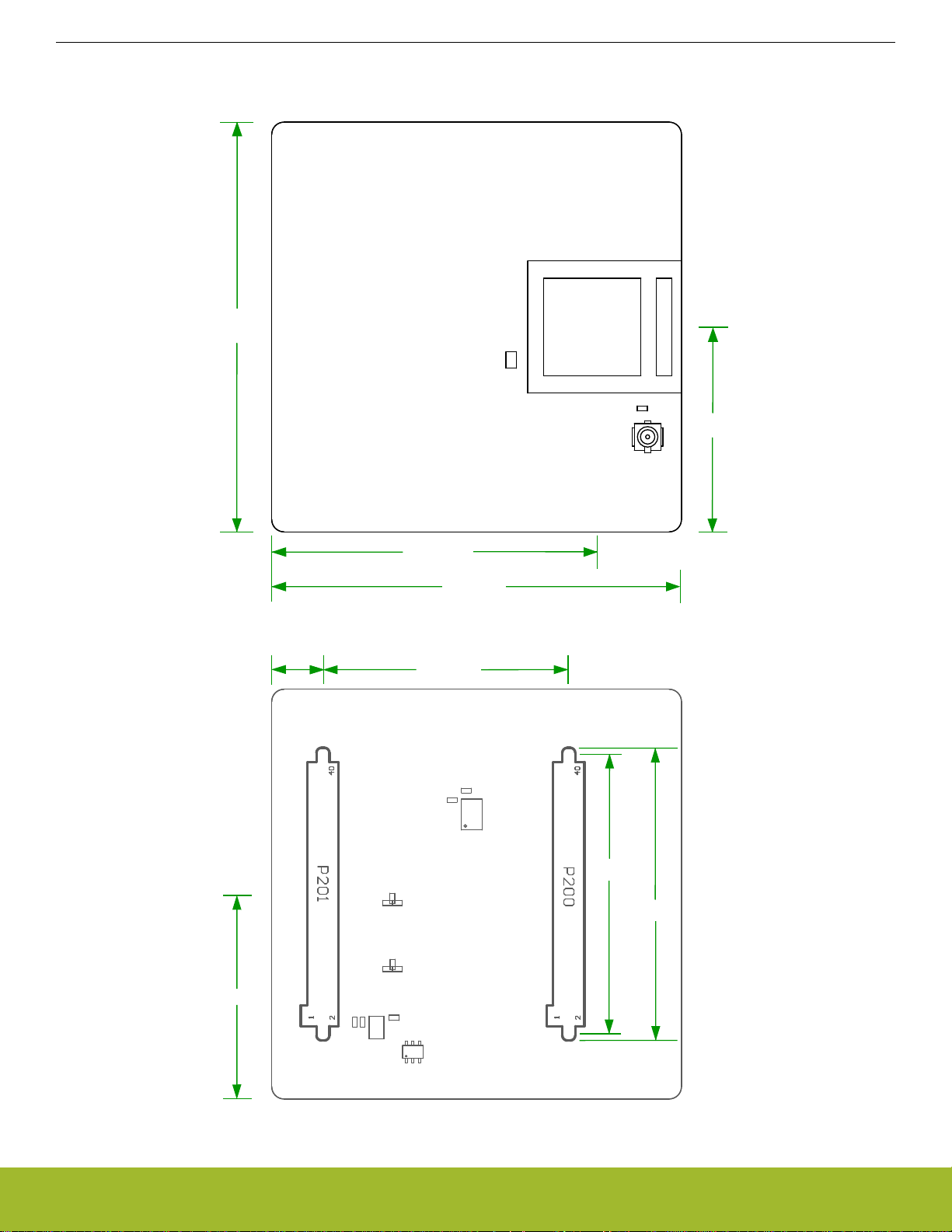
The BRD4308D Radio Board is illustrated in the figures below.
BRD4308D Reference Manual
Mechanical Details
Figure 4.1. BRD4308D Top View
silabs.com | Building a more connected world. Rev. 1.0 | 6
Figure 4.2. BRD4308D Bottom View
Page 7
BRD4308D Reference Manual
EMC Compliance
5. EMC Compliance
5.1 Introduction
Compliance of the fundamental and harmonic levels of the BRD4308D Radio Board is tested against the following standards:
• 2.4 GHz:
• ETSI EN 300-328
• FCC 15.247
5.2 EMC Regulations for 2.4 GHz
5.2.1 ETSI EN 300-328 Emission Limits for the 2400-2483.5 MHz Band
Based on ETSI EN 300-328, the allowed maximum fundamental power for the 2400-2483.5 MHz band is 20 dBm EIRP. For the unwanted emissions in the 1 GHz to 12.75 GHz domain, the specific limit is -30 dBm EIRP.
5.2.2 FCC15.247 Emission Limits for the 2400-2483.5 MHz Band
FCC 15.247 allows conducted output power up to 1 W (30 dBm) in the 2400-2483.5 MHz band. For spurious emissions, the limit is
-20 dBc based on either conducted or radiated measurement, if the emission is not in a restricted band. The restricted bands are specified in FCC 15.205. In these bands, the spurious emission levels must meet the levels set out in FCC 15.209. In the range from
960 MHz to the frequency of the 5th harmonic, it is defined as 0.5 mV/m at 3 m distance which equals to -41.2 dBm in EIRP.
If operating in the 2400-2483.5 MHz band, the 2nd, 3rd, and 5th harmonics can fall into restricted bands. As a result, for those harmonics the -41.2 dBm limit should be applied. For the 4th harmonic the -20 dBc limit should be applied.
5.2.3 Applied Emission Limits for the 2.4 GHz Band
The above ETSI limits are applied both for conducted and radiated measurements.
The FCC restricted band limits are radiated limits only. In addition, Silicon Labs applies the same restrictions to the conducted spectrum. By doing so, compliance with the radiated limits can be estimated based on the conducted measurement, by assuming the use of
an antenna with 0 dB gain at the fundamental and the harmonic frequencies.
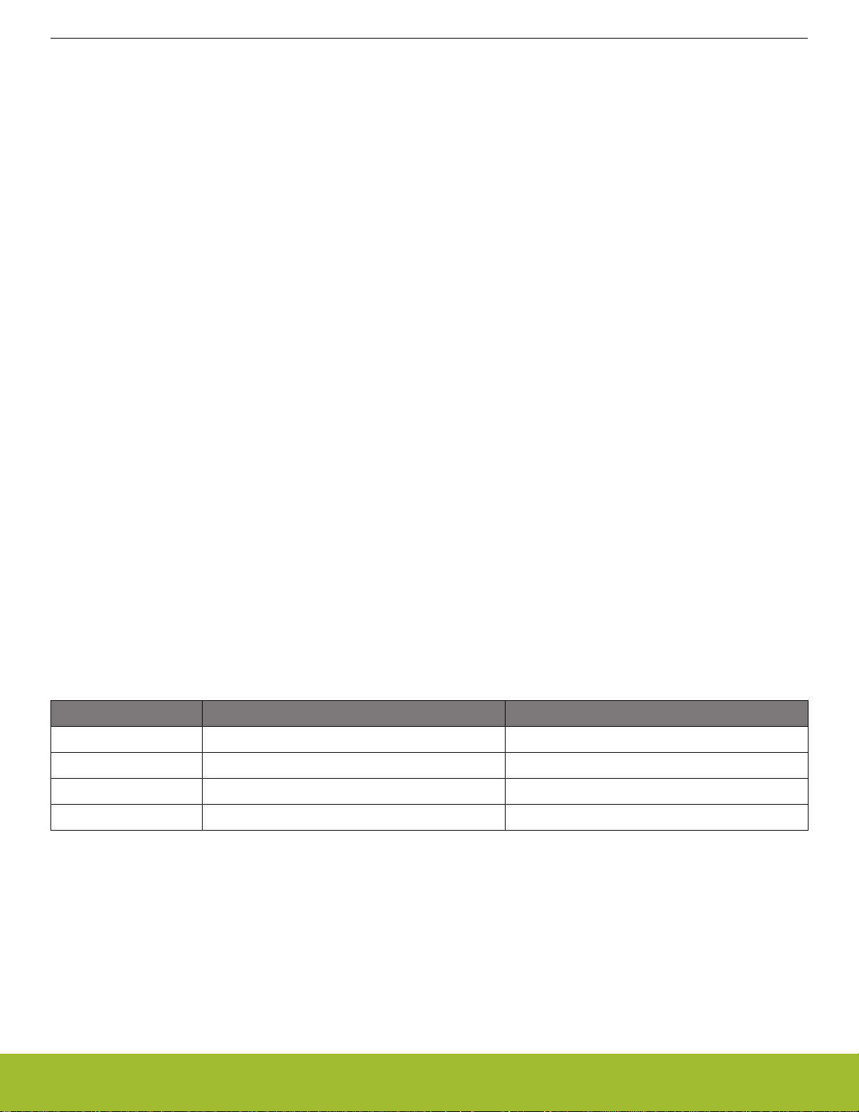
The overall applied limits are shown in the table below. For the harmonics that fall into the FCC restricted bands, the FCC 15.209 limit is
applied. ETSI EN 300-328 limit is applied for the rest.
Table 5.1. Applied Limits for Spurious Emissions for the 2.4 GHz Band
Harmonic Frequency Limit
2nd 4800~4967 MHz -41.2 dBm
3rd 7200~7450.5 MHz -41.2 dBm
4th 9600~9934 MHz -30.0 dBm
5th 12000~12417.5 MHz -41.2 dBm
silabs.com | Building a more connected world. Rev. 1.0 | 7
Page 8
BRD4308D Reference Manual
RF Performance
6. RF Performance
6.1 Conducted Power Measurements
During measurements, the BRD4308D Radio Board was attached to a Wireless Starter Kit Mainboard which was supplied by USB. The
voltage supply for the Radio Board was 3.3 V.
6.1.1 Conducted Measurements in the 2.4 GHz Band
The BRD4308D Radio Board was connected directly to a Spectrum Analyzer through the on-board UFL connector. The RF output of
the module was set to the RF2G4_IO2 pin instead of the built-in antenna.
The supply for the module (VDD) was 3.3 V provided by the mainboard; for details, see the BRD4308D schematic. The transceiver was
operated in continuous carrier transmission mode. The output power of the radio was set to 10 dBm.
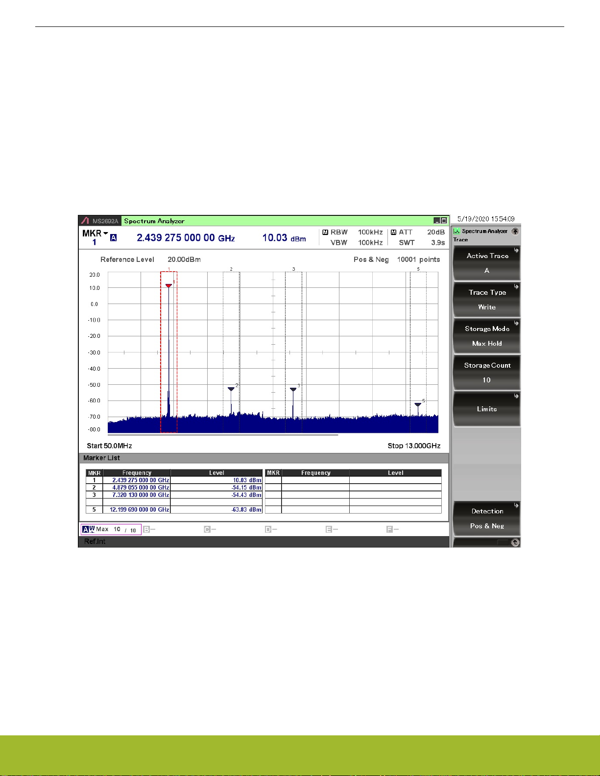
The typical output spectrum is shown in the following figure.
Figure 6.1. Typical Output Spectrum of the BRD4308D
As shown in the figure above, the fundamental is 10 dBm and all of the unwanted emissions are under the applied limits.
Note: The UFL connector introduces approximately 0.3 dB insertion loss.
silabs.com | Building a more connected world. Rev. 1.0 | 8
Page 9
xGM210PB22
X
Z
Y
BRD4308D Reference Manual
RF Performance
6.2 Radiated Power Measurements
During measurements, the BRD4308D Radio Board was attached to a Wireless Starter Kit Mainboard which was supplied by USB. The
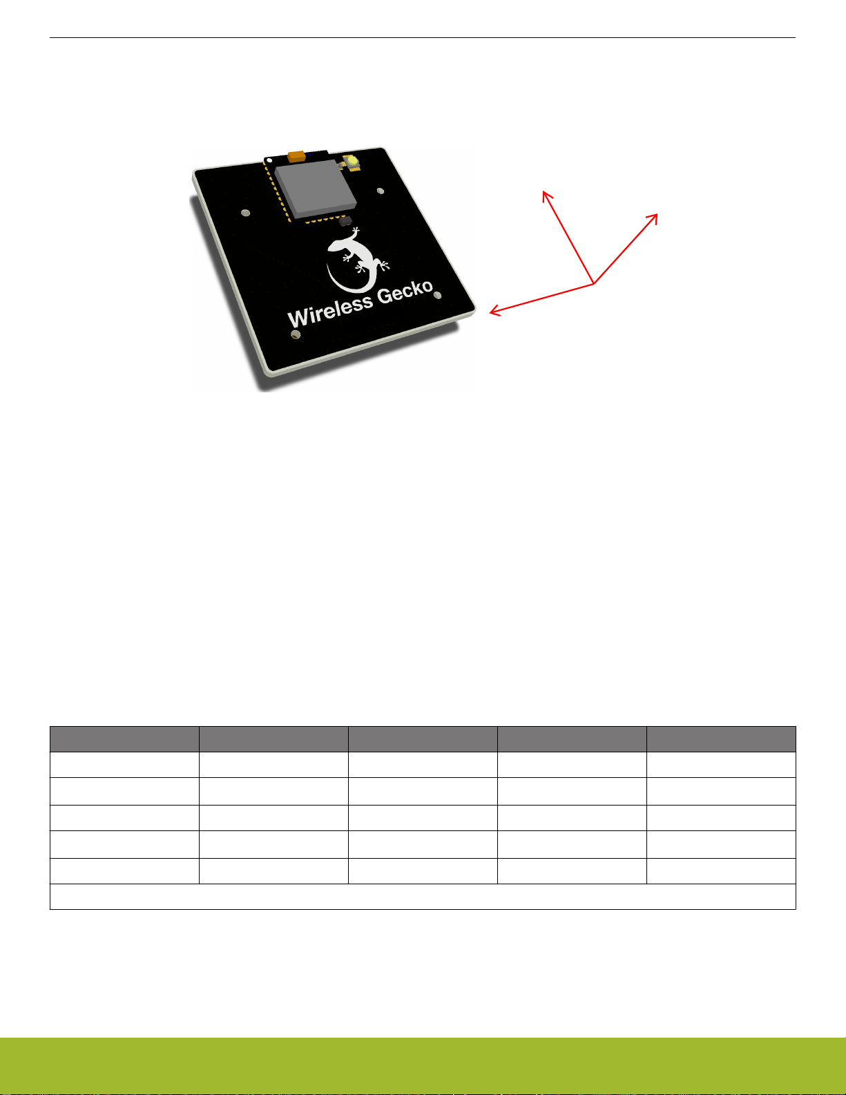
voltage supply for the Radio Board was 3.3 V. The radiated power was measured in an antenna chamber by rotating the board 360 degrees with horizontal and vertical reference antenna polarizations in the XY, XZ, and YZ cuts. The measurement planes are illustrated
in the figure below.
Figure 6.2. Illustration of Reference Planes with a Radio Board Plugged into the Wireless Starter Kit Mainboard
Note: The radiated measurement results presented in this document were recorded in an unlicensed antenna chamber. Also, the radi-
ated power levels may change depending on the actual application (PCB size, used antenna, and so on). Therefore, the absolute levels
and margins of the final application are recommended to be verified in a licensed EMC testhouse.
6.2.1 Radiated Measurements in the 2.4 GHz Band
The supply for the module (VDD) was 3.3 V provided by the mainboard; for details, see the BRD4308D schematic. The RF output of the
module was set to the built-in antenna. The transceiver was operated in continuous carrier transmission mode. The output power of the
radio was set to 10 dBm based on the conducted measurement.
The fundamental was set to the frequency where the maximum antenna gain was measured. The results are shown in the table below.
Note: The frequency in which the antenna gain has its maximum value can vary between modules due to the technological spreading
of the passive RF components and the antenna.
Table 6.1. Maximums of the Measured Radiated Powers in EIRP [dBm]
Frequency (2440 MHz) EIRP [dBm] Orientation Margin [dB] Limit in EIRP [dBm]
Fund 11.6 XY/H 18.4 30.0
2nd
3rd -44.4 XZ/H 3.3 -41.2
4th
<-50
<-50
*
*
-/- >10 -41.2
-/- >20 -30.0
5th -42.7 XY/V 1.5 -41.2
* Signal level is below the Spectrum Analyzer noise floor.
As shown in the table above, due to the antenna gain, the fundamental is slightly higher than the output power based the conducted
measurement. The harmonics are below the applied limits.
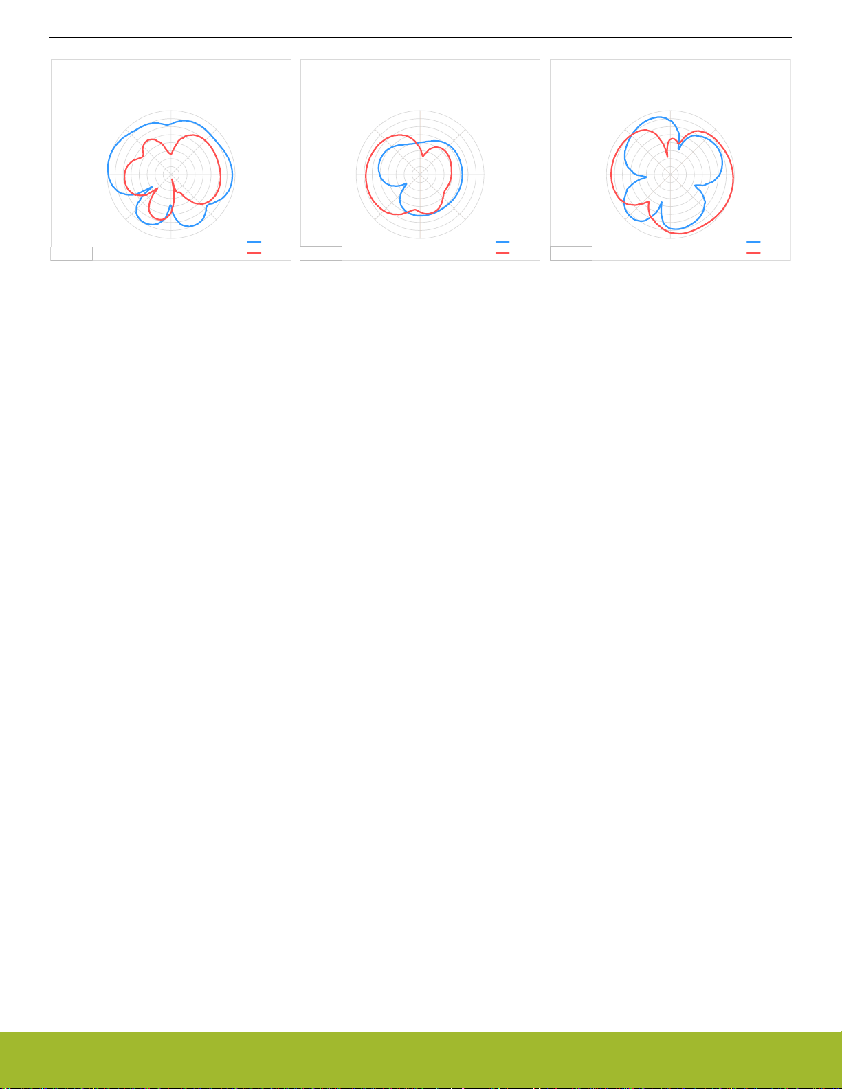
6.2.2 Antenna Pattern Measurements
The measured normalized antenna patterns are shown in the following figures.
silabs.com | Building a more connected world. Rev. 1.0 | 9
Page 10
0°
45°
90°
135°
180°
225°
270°
315°
-40
-35
-30
-25
-20
-15
-10
-5
0
Normalized Radiation Pattern [dB], BRD4308D
with WSTK, YZ cut
Horizontal
Vertical
0°= Z axis
0°
45°
90°
135°
180°
225°
270°
315°
-40
-35
-30
-25
-20
-15
-10
-5
0
Normalized Radiation Pattern [dB], BRD4308D
with WSTK, XZ cut
Horizontal
Vertical
0°= Z axis
0°
45°
90°
135°
180°
225°
270°
315°
-40
-35
-30
-25
-20
-15
-10
-5
0
Normalized Radiation Pattern [dB], BRD4308D
with WSTK, XY cut
Horizontal
Vertical
0°= X axis
BRD4308D Reference Manual
RF Performance
Figure 6.3. Normalized Antenna Pattern of the BRD4308D with the Wireless Starter Kit Mainboard
silabs.com | Building a more connected world. Rev. 1.0 | 10
Page 11

BRD4308D Reference Manual
EMC Compliance Recommendations
7. EMC Compliance Recommendations
7.1 Recommendations for 2.4 GHz ETSI EN 300-328 Compliance
As shown in section 6.2 Radiated Power Measurements, the power of the fundamental frequency of the BRD4308D Wireless Gecko
Radio Board with 10 dBm output is compliant with the 20 dBm limit of the ETSI EN 300-328 regulation in both the conducted and radiated measurements. The harmonic emissions are under the -30 dBm limit with large margin.
7.2 Recommendations for 2.4 GHz FCC 15.247 Compliance
As shown in section 6.2 Radiated Power Measurements, the power of the fundamental frequency of the BRD4308D Wireless Gecko
Radio Board with 10 dBm output is compliant with the 30 dBm limit of the FCC 15.247 regulation. The harmonic emissions are under
the applied limits.
silabs.com | Building a more connected world. Rev. 1.0 | 11
Page 12
Board
Revision
PCB
Revision
BRD4308D Rev. A00
PCB4308D Rev. A01
123456789
BRD4308D Reference Manual
Board Revision History
8. Board Revision History
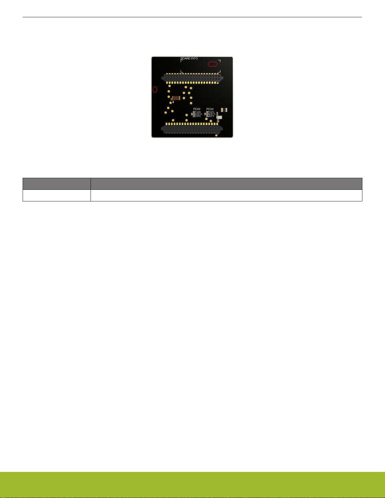
The board revision is laser engraved in the Board Info field on the bottom side of the PCB, as outlined in the figure below. The revision
printed on the silkscreen is the PCB revision.
Figure 8.1. Revision Info
Table 8.1. BRD4308D Radio Board Revision History
Board Revision Description
A00 Initial production release based on BRD4308B Rev. A02. New module OPN.
silabs.com | Building a more connected world. Rev. 1.0 | 12
Page 13

9. Errata
There are no known errata at present.
BRD4308D Reference Manual
Errata
silabs.com | Building a more connected world. Rev. 1.0 | 13
Page 14

10. Document Revision History
Revision 1.0
Aug, 2020
• Initial document release.
BRD4308D Reference Manual
Document Revision History
silabs.com | Building a more connected world. Rev. 1.0 | 14
Page 15

Simplicity Studio
One-click access to MCU and wireless
tools, documentation, software, source
code libraries & more. Available for
Windows, Mac and Linux!
IoT Portfolio
www.silabs.com/IoT
Disclaimer
Silicon Labs intends to provide customers with the latest, accurate, and in-depth documentation of all peripherals and modules available for system and software implementers using or
intending to use the Silicon Labs products. Characterization data, available modules and peripherals, memory sizes and memory addresses refer to each specific device, and “Typical”
parameters provided can and do vary in different applications. Application examples described herein are for illustrative purposes only. Silicon Labs reserves the right to make changes
without further notice to the product information, specifications, and descriptions herein, and does not give warranties as to the accuracy or completeness of the included information.
Without prior notification, Silicon Labs may update product firmware during the manufacturing process for security or reliability reasons. Such changes will not alter the specifications or
the performance of the product. Silicon Labs shall have no liability for the consequences of use of the information supplied in this document. This document does not imply or expressly
grant any license to design or fabricate any integrated circuits. The products are not designed or authorized to be used within any FDA Class III devices, applications for which FDA
premarket approval is required, or Life Support Systems without the specific written consent of Silicon Labs. A “Life Support System” is any product or system intended to support or
sustain life and/or health, which, if it fails, can be reasonably expected to result in significant personal injury or death. Silicon Labs products are not designed or authorized for military
applications. Silicon Labs products shall under no circumstances be used in weapons of mass destruction including (but not limited to) nuclear, biological or chemical weapons, or
missiles capable of delivering such weapons. Silicon Labs disclaims all express and implied warranties and shall not be responsible or liable for any injuries or damages related to use of
a Silicon Labs product in such unauthorized applications.
Trademark Information
Silicon Laboratories Inc.®, Silicon Laboratories®, Silicon Labs®, SiLabs® and the Silicon Labs logo®, Bluegiga®, Bluegiga Logo®, ClockBuilder®, CMEMS®, DSPLL®, EFM®,
EFM32®, EFR, Ember®, Energy Micro, Energy Micro logo and combinations thereof, “the world’s most energy friendly microcontrollers”, Ember®, EZLink®, EZRadio®, EZRadioPRO®,
Gecko®, Gecko OS, Gecko OS Studio, ISOmodem®, Precision32®, ProSLIC®, Simplicity Studio®, SiPHY®, Telegesis, the Telegesis Logo®, USBXpress®, Zentri, the Zentri logo and
Zentri DMS, Z-Wave®, and others are trademarks or registered trademarks of Silicon Labs. ARM, CORTEX, Cortex-M3 and THUMB are trademarks or registered trademarks of ARM
Holdings. Keil is a registered trademark of ARM Limited. Wi-Fi is a registered trademark of the Wi-Fi Alliance. All other products or brand names mentioned herein are trademarks of
their respective holders.
Silicon Laboratories Inc.
400 West Cesar Chavez
Austin, TX 78701
USA
http: //www.silabs.com
www.silabs.com/simplicit y
SW/HW
Quality
www.silabs.com/quality
Support & Community
www.silabs.com/community
 Loading...