

Page 1

SGI® ICE™ X System
Hardware User Guide
Document Number 007-5806-004
Page 2

COPYRIGHT
© 2013-2015 Silicon Graphics International Corporation. All rights reserved; provided portions may be copyright in third parties, as indicated elsewhere herein.
No permission is granted to copy, distribute, or create derivative works from the contents of this electronic documentation in any manner, in whole or in part,
without the prior written permission of SGI.
LIMITED RIGHTS LEGEND
The software described in this document is "commercial computer software" provided with restricted rights (except as to included open/free source) as specified
in the FAR 52.227-19 and/or the DFAR 227.7202, or successive sections. Use beyond license provisions is a violation of worldwide intellectual property laws,
treaties and conventions. This document is provided with limited rights as defined in 52.227-14.
The electronic (software) version of this document was developed at private expense; if acquired under an agreement with the USA government or any
contractor thereto, it is acquired as “commercial computer software” subject to the provisions of its applicable license agreement, as specified in (a) 48 CFR
12.212 of the FAR; or, if acquired for Department of Defense units, (b) 48 CFR 227-7202 of the DoD FAR Supplement; or sections succeeding thereto.
Contractor/manufacturer is SGI, 900 North McCarthy Blvd. Milpitas, CA 95035.
TRADEMARKS AND ATTRIBUTIONS
SGI, and the SGI logo are registered trademarks and Rackable, SGI Lustre and SGI ICE are trademarks of, Silicon Graphics International, in the United States
and/or other countries worldwide.
Intel, Intel QuickPath Interconnect (QPI), Itanium and Xeon are trademarks or registered trademarks of Intel Corporation or its subsidiaries in the United States
and other countries.
UNIX is a registered trademark in the United States and other countries, licensed exclusively through X/Open Company, Ltd.
Infiniband is a trademark of the InfiniBand Trade Association.
Red Hat and all Red Hat-based trademarks are trademarks or registered trademarks of Red Hat, Inc. in the United States and other countries.
Linux is a registered trademark of Linus Torvalds.
All other trademarks mentioned herein are the property of their respective owners.
Page 3

Record of Revision
Version Description
-001 March, 2012
First release
-002 February, 2013
Blade and rack design updates
-003 June, 2014
Blade updates
-004 November, 2015
cpower command and service reference updates
007-5806-004 iii
Page 4

Page 5

Contents
List of Figures . . . . . . . . . . . . . . . . . . . . . . . . xi
List of Tables . . . . . . . . . . . . . . . . . . . . . . . . xiii
Audience. . . . . . . . . . . . . . . . . . . . . . . . . . xv
Important Information . . . . . . . . . . . . . . . . . . . . . . xv
Chapter Descriptions . . . . . . . . . . . . . . . . . . . . . . xvi
Related Publications . . . . . . . . . . . . . . . . . . . . . . .xvii
Obtaining SGI Publications. . . . . . . . . . . . . . . . . . . xviii
Conventions . . . . . . . . . . . . . . . . . . . . . . . . . xix
Product Support . . . . . . . . . . . . . . . . . . . . . . . . xix
Reader Comments . . . . . . . . . . . . . . . . . . . . . . . xx
1. Operation Procedures . . . . . . . . . . . . . . . . . . . . . . 1
Precautions . . . . . . . . . . . . . . . . . . . . . . . . . 1
ESD Precaution . . . . . . . . . . . . . . . . . . . . . . . 1
Safety Precautions . . . . . . . . . . . . . . . . . . . . . . 2
Console Connections . . . . . . . . . . . . . . . . . . . . . . 3
Powering the System On and Off . . . . . . . . . . . . . . . . . . . 4
Preparing to Power On . . . . . . . . . . . . . . . . . . . . . 5
Powering On and Off . . . . . . . . . . . . . . . . . . . . . 8
Console Management Power (cpower) Commands . . . . . . . . . . . . 8
Monitoring Your Server . . . . . . . . . . . . . . . . . . . . . . 12
Optional SGI Remote Services (SGI RS) . . . . . . . . . . . . . . . . . 13
SGI Remote Services Primary Capabilities . . . . . . . . . . . . . . . 14
SGI Remote Services Benefits . . . . . . . . . . . . . . . . . . . 14
SGI Remote Service Operations Overview. . . . . . . . . . . . . . . . 14
007-5806-004 v
Page 6

Contents
2. System Management . . . . . . . . . . . . . . . . . . . . . . 17
Using the 1U Console Option . . . . . . . . . . . . . . . . . . . . 19
Levels of System and Chassis Control . . . . . . . . . . . . . . . . . . 19
Chassis Controller Interaction . . . . . . . . . . . . . . . . . . . . 19
Chassis Manager Interconnects . . . . . . . . . . . . . . . . . . . 20
M-rack Chassis Manager Interconnection . . . . . . . . . . . . . . . 21
Chassis Management Control (CMC) Functions . . . . . . . . . . . . . . 22
CMC Connector Ports and Indicators . . . . . . . . . . . . . . . . . 23
System Power Status . . . . . . . . . . . . . . . . . . . . . . . 23
3. System Overview . . . . . . . . . . . . . . . . . . . . . . . 25
System Models . . . . . . . . . . . . . . . . . . . . . . . . 26
SGI ICE X System and Blade Architectures . . . . . . . . . . . . . . . . . 29
IP113 Blade Architecture Overview . . . . . . . . . . . . . . . . . 29
IP115 Blade Architecture Overview . . . . . . . . . . . . . . . . . 30
IP119 Blade Architecture Overview . . . . . . . . . . . . . . . . . 31
IP131 Blade Architecture Overview . . . . . . . . . . . . . . . . . 32
IP133 Blade Architecture Overview . . . . . . . . . . . . . . . . . 33
QuickPath Interconnect Features. . . . . . . . . . . . . . . . . . . . 34
IP113, IP115 and IP119 QPI Bandwidth . . . . . . . . . . . . . . . . 34
IP131 and IP133 QPI Bandwidth . . . . . . . . . . . . . . . . . . 34
Blade Memory Features . . . . . . . . . . . . . . . . . . . . . 35
Blade DIMM Memory Features . . . . . . . . . . . . . . . . . 35
Memory Channel Recommendation . . . . . . . . . . . . . . . . 35
Blade DIMM Bandwidth Factors . . . . . . . . . . . . . . . . . 35
System InfiniBand Switch Blades . . . . . . . . . . . . . . . . . . 36
Enclosure Switch Density Choices . . . . . . . . . . . . . . . . . 36
vi 007-5806-004
Page 7

Contents
System Features and Major Components . . . . . . . . . . . . . . . . . 38
Modularity and Scalability . . . . . . . . . . . . . . . . . . . . 38
System Administration Server . . . . . . . . . . . . . . . . . . 39
Rack Leader Controller . . . . . . . . . . . . . . . . . . . 40
Multiple Chassis Manager Connections . . . . . . . . . . . . . . . 40
The RLC as Fabric Manager . . . . . . . . . . . . . . . . . . 41
Service Nodes . . . . . . . . . . . . . . . . . . . . . . . 42
Login Server Function . . . . . . . . . . . . . . . . . . . . 42
Batch Server Node . . . . . . . . . . . . . . . . . . . . . 43
I/O Gateway Node . . . . . . . . . . . . . . . . . . . . . 43
Optional Lustre Nodes Overview . . . . . . . . . . . . . . . . . . 44
MDS Node . . . . . . . . . . . . . . . . . . . . . . . 44
OSS Node . . . . . . . . . . . . . . . . . . . . . . . 45
Reliability, Availability, and Serviceability (RAS) . . . . . . . . . . . . . 45
System Components . . . . . . . . . . . . . . . . . . . . . . . 47
D-Rack Unit Numbering . . . . . . . . . . . . . . . . . . . . 51
Rack Numbering . . . . . . . . . . . . . . . . . . . . . . 51
Optional System Components . . . . . . . . . . . . . . . . . . . 51
Optional SGI Remote Services (SGI RS) . . . . . . . . . . . . . . . . . 51
SGI Remote Services Primary Capabilities . . . . . . . . . . . . . . . 52
SGI Remote Services Benefits . . . . . . . . . . . . . . . . . . . 52
SGI Remote Service Operations Overview. . . . . . . . . . . . . . . . 53
SGI Warranty Levels . . . . . . . . . . . . . . . . . . . . . 54
4. Rack Information . . . . . . . . . . . . . . . . . . . . . . . 55
Overview . . . . . . . . . . . . . . . . . . . . . . . . . 55
SGI ICE X Series D-Rack (42U) . . . . . . . . . . . . . . . . . . . 56
ICE X D-Rack Technical Specifications . . . . . . . . . . . . . . . . . 61
SGI ICE X M-Cell Rack Assemblies . . . . . . . . . . . . . . . . . . 62
M-Cell Functional Overview . . . . . . . . . . . . . . . . . . . 63
007-5806-004 vii
Page 8

Contents
5. SGI ICE X Administration/Leader Servers . . . . . . . . . . . . . . . . 67
Overview . . . . . . . . . . . . . . . . . . . . . . . . . . 68
System Hierarchy . . . . . . . . . . . . . . . . . . . . . . 68
Communication Hierarchy . . . . . . . . . . . . . . . . . . . 69
1U Rack Leader Controller and Administration Server . . . . . . . . . . . . . . 71
1U Service Nodes . . . . . . . . . . . . . . . . . . . . . . . 72
C1104G-RP5 1U Service Node . . . . . . . . . . . . . . . . . . . 72
2U Service Nodes . . . . . . . . . . . . . . . . . . . . . . . 74
RP2 2U Service Nodes . . . . . . . . . . . . . . . . . . . . . 74
RP2 Service Node Front Controls . . . . . . . . . . . . . . . . . 74
RP2 Service Node Back Panel Components . . . . . . . . . . . . . . 76
C2110G-RP5-P 2U Service Node . . . . . . . . . . . . . . . . . . 77
SGI UV 20 2U Service Node . . . . . . . . . . . . . . . . . . . 79
6. Basic Troubleshooting . . . . . . . . . . . . . . . . . . . . . . 81
Troubleshooting Chart . . . . . . . . . . . . . . . . . . . . . . 82
LED Status Indicators . . . . . . . . . . . . . . . . . . . . . . 83
Blade Enclosure Pair Power Supply LEDs . . . . . . . . . . . . . . . . 83
IP113 Compute Blade LEDs . . . . . . . . . . . . . . . . . . . 84
IP115 Compute Blade Status LEDs . . . . . . . . . . . . . . . . . . 85
IP119 Compute Blade Status LEDs . . . . . . . . . . . . . . . . . . 87
IP131 Compute Blade Status LEDs . . . . . . . . . . . . . . . . . . 88
IP133 Compute Blade Status LEDs . . . . . . . . . . . . . . . . . . 89
Accessing Online Support Information and Services . . . . . . . . . . . . . . 90
SGI Customer Portal. . . . . . . . . . . . . . . . . . . . . . 90
Technical Assistance . . . . . . . . . . . . . . . . . . . . . 91
Other Resources . . . . . . . . . . . . . . . . . . . . . . . 91
SGI Warranty Levels . . . . . . . . . . . . . . . . . . . . . 91
Optional SGI Remote Services (SGI RS) . . . . . . . . . . . . . . . . 92
7. Maintenance Procedures . . . . . . . . . . . . . . . . . . . . . 93
Maintenance Precautions and Procedures . . . . . . . . . . . . . . . . . 93
Preparing the System for Maintenance or Upgrade . . . . . . . . . . . . . . 94
Installing or Removing Internal Parts . . . . . . . . . . . . . . . . . . 94
viii 007-5806-004
Page 9

Contents
Replacing ICE X System Components . . . . . . . . . . . . . . . . . . 95
Removing and Replacing a Blade Enclosure Power Supply . . . . . . . . . . . 95
Removing and Replacing Rear Fans (Blowers) . . . . . . . . . . . . . . 98
Removing or Replacing a Fan Enclosure Power Supply . . . . . . . . . . . .102
Removing a Fan Assembly Power Supply . . . . . . . . . . . . . . . .102
Replacing a Fan Power Supply . . . . . . . . . . . . . . . . . . .102
Overview of PCI Express Operation . . . . . . . . . . . . . . . . . .105
A. Technical Specifications and Pinouts . . . . . . . . . . . . . . . . . .107
System-level Specifications . . . . . . . . . . . . . . . . . . . . .107
D-Rack Physical and Power Specifications . . . . . . . . . . . . . . .108
D-Rack System Environmental Specifications . . . . . . . . . . . . . . .109
ICE X M-Rack Technical Specifications . . . . . . . . . . . . . . . .110
Ethernet Port Specification . . . . . . . . . . . . . . . . . . . .112
B. Safety Information and Regulatory Specifications . . . . . . . . . . . . . .113
Safety Information . . . . . . . . . . . . . . . . . . . . . . .113
Regulatory Specifications . . . . . . . . . . . . . . . . . . . . .115
CMN Number . . . . . . . . . . . . . . . . . . . . . . .115
CE Notice and Manufacturer’s Declaration of Conformity . . . . . . . . . . .115
Electromagnetic Emissions . . . . . . . . . . . . . . . . . . . .115
FCC Notice (USA Only) . . . . . . . . . . . . . . . . . . .116
Industry Canada Notice (Canada Only) . . . . . . . . . . . . . . .116
VCCI Notice (Japan Only). . . . . . . . . . . . . . . . . . .117
Chinese Class A Regulatory Notice . . . . . . . . . . . . . . . .117
Korean Class A Regulatory Notice . . . . . . . . . . . . . . . .117
Shielded Cables . . . . . . . . . . . . . . . . . . . . . . .118
Electrostatic Discharge and Laser Compliance. . . . . . . . . . . . . . .118
Lithium Battery Statements. . . . . . . . . . . . . . . . . . . .119
Index . . . . . . . . . . . . . . . . . . . . . . . . . .121
007-5806-004 ix
Page 10

Page 11

List of Figures
Figure 1-1 Flat Panel Rackmount Console Option . . . . . . . . . . 3
Figure 1-2 Administrative Controller Video Console Connection Points . . . . 4
Figure 1-3 Blade Enclosure Power Supply Cable Example . . . . . . . . 5
Figure 1-4 Eight-Outlet Single-Phase PDU Example . . . . . . . . . 6
Figure 1-5 Three-Phase PDU Examples . . . . . . . . . . . . . 7
Figure 1-6 Blade Enclosure Chassis Management Board Locations . . . . . 13
Figure 1-7 SGI Remote Services Process Overview. . . . . . . . . . 15
Figure 2-1 SGI ICE X System Network Access Example . . . . . . . . 18
Figure 2-2 Redundant Chassis Manager Interconnect Diagram Example . . . . 20
Figure 2-3 Non-redundant Chassis Manager Interconnection Diagram Example . . 21
Figure 2-4 M-rack System Chassis Manager Interconnect Example . . . . . 22
Figure 2-5 Chassis Management Controller Board Front Panel Ports and Indicators . 23
Figure 3-1 SGI ICE X Series System (Single Rack - Air Cooled Example) . . . 26
Figure 3-2 D-rack Blade Enclosure and Rack Components Example . . . . . 28
Figure 3-3 InfiniBand 48-port (Premium) FDR Switch Numbering in Blade Enclosures 37
Figure 3-4 SGI ICE X System and Network Components Overview . . . . . 39
Figure 3-5 D-Rack Administration and RLC Cabling to CMCs Example . . . . 41
Figure 3-6 Example Rear View of a 1U Service Node . . . . . . . . . 42
Figure 3-7 2U Service Node Front and Rear Panel Example . . . . . . . 43
Figure 3-8 SGI ICE X Series D-Rack Blade Enclosure Pair Components Example . 48
Figure 3-9 Single-node D-Rack Blade Enclosure Pair Component Front Diagram . . 49
Figure 3-10 M-Rack Blade Enclosure Pair Components Example . . . . . . 50
Figure 3-11 SGI Remote Services Process Overview. . . . . . . . . . 53
Figure 4-1 SGI ICE X Series D-Rack Example . . . . . . . . . . . 57
Figure 4-2 Front Lock on Tall (42U) D-Rack . . . . . . . . . . . 58
Figure 4-3 Optional Water-Chilled Door Panels on Rear of ICE X D-Rack . . . 59
Figure 4-4 Air-Cooled D-Rack Rear Door and Lock Example . . . . . . . 60
007-5806-004 xi
Page 12

List of Figures
Figure 4-5 M-Cell Rack Configuration Example (Top View) . . . . . . . 62
Figure 4-6 SGI ICE X Multi-Cell (M-Cell) Rack Array Example . . . . . . 64
Figure 4-7 Half M-Cell Rack Assembly (½-Cell) Example . . . . . . . . 65
Figure 5-1 SGI ICE X System Administration Hierarchy Example Diagram . . . 70
Figure 5-2 1U Rack Leader Controller (RLC) Server Front and Rear Panels . . . 71
Figure 5-3 SGI Rackable C1104G-RP5 1U Service Node Front and Rear Panels . . 73
Figure 5-4 SGI Rackable C1104G-RP5 System Control Panel and LEDs . . . . 73
Figure 5-5 8-HDD Configuration RP2 Service Node Front Panel Example . . . . 74
Figure 5-6 C2108-RP2 Service Node Front Control Panel—Horizontal Layout. . . 74
Figure 5-7 RP2 Service Node Back Panel Components Example . . . . . . 76
Figure 5-8 Front and Rear Views of the SGI C2110G-RP5-P 2U Service Node. . . 77
Figure 5-9 SGI Rackable C2110G-RP5-P 2U Service Node Control Panel Diagram . 78
Figure 5-10 SGI UV 20 Service Node Front Panel Example . . . . . . . . 79
Figure 5-11 SGI UV 20 Service Node Rear Panel and Component Descriptions . . . 79
Figure 5-12 SGI UV 20 Service Node Front Control Panel Description . . . . . 80
Figure 6-1 Power Supply Status LED Indicator Locations . . . . . . . . 83
Figure 6-2 IP113 Compute Blade Status LED Locations Example . . . . . . 84
Figure 6-3 IP115 Compute Blade Status LEDs Example. . . . . . . . . 85
Figure 6-4 IP119 Blade Status LEDs Example . . . . . . . . . . . 87
Figure 6-5 IP131 Compute Blade Status LED Locations Example . . . . . . 88
Figure 6-6 IP133 Blade Status LEDs Example . . . . . . . . . . . 89
Figure 7-1 Removing an Enclosure Power Supply . . . . . . . . . . 96
Figure 7-2 Replacing an Enclosure Power Supply . . . . . . . . . . 97
Figure 7-3 Enclosure-Pair Rear Fan Assembly (Blowers) . . . . . . . . 99
Figure 7-4 Removing a Fan From the Rear Assembly . . . . . . . . 100
Figure 7-5 Replacing an Enclosure Fan . . . . . . . . . . . . 101
Figure 7-6 Removing a Power Supply From the Fan Power Box . . . . . 103
Figure 7-7 Replacing a Power Supply in the Fan Power Box . . . . . . 104
Figure 7-8 Comparison of PCI/PCI-X Connector with PCI Express Connectors . 105
Figure A-1 Ethernet Port . . . . . . . . . . . . . . . . 112
Figure B-1 VCCI Notice (Japan Only) . . . . . . . . . . . . 117
Figure B-2 Chinese Class A Regulatory Notice . . . . . . . . . . 117
Figure B-3 Korean Class A Regulatory Notice . . . . . . . . . . 117
xii 007-5806-004
Page 13

List of Tables
Table 1-1 cpower option, action, target type and target list descriptions . . . . 8
Table 1-2 cpower example command strings . . . . . . . . . . . 11
Table 4-1 Tall SGI ICE X D-Rack Technical Specifications . . . . . . . 61
Table 4-2 SGI ICE X M-Rack Technical Specifications . . . . . . . . 63
Table 5-1 C2108-RP2 Control Panel Components . . . . . . . . . . 75
Table 5-2 RP2 Service Node Back Panel Components . . . . . . . . . 76
Table 5-3 C2110G-RP5-P 2U Server Control Panel Functions (listed top to bottom) . 78
Table 6-1 Troubleshooting Chart . . . . . . . . . . . . . . 82
Table 6-2 Power Supply LED States . . . . . . . . . . . . . 83
Table 7-1 Customer-replaceable Components and Maintenance Procedures . . . 94
Table 7-2 SGI Administrative Server PCIe Support Levels . . . . . . .106
Table A-1 SGI ICE X Series Configuration Ranges . . . . . . . . .107
Table A-2 ICE X System D-Rack Physical Specifications . . . . . . . .108
Table A-3 Environmental Specifications (Single D-Rack) . . . . . . . .109
Table A-4 SGI ICE X M-Rack Physical Specifications . . . . . . . . .110
Table A-5 Environmental Specifications (Single M-Rack) . . . . . . . .111
Table A-6 Ethernet Pinouts . . . . . . . . . . . . . . . . 112
007-5806-004 xiii
Page 14

Page 15
About This Guide
This guide provides an overview of the architecture, general operation and descriptions of the
major components that compose the SGI
enclosure systems. It also provides the standard procedures for powering on and powering off the
system, basic troubleshooting information, customer maintenance procedures and important
safety and regulatory specifications.
Audience
This guide is written for owners, system administrators, and users of SGI ICE X series computer
systems.
It is written with the assumption that the reader has a good working knowledge of computers and
computer s
Important Information
Warning: To avoid problems that could void your warranty, your SGI or other approved
service technician should perform al
and service of your SGI ICE X series system, with the exception of the following items that
you can perform yourself:
ystems.
®
Integrated Compute Environment (ICE™) X series blade
l the setup, addition, or replacement of parts, cabling,
• Using your system console or network access workstation to enter commands and perform
system functions such as powering on and powering off, as described in this guide.
• Removing and replacing power supplies and
• Adding and replacing disk drives in optional storage sy
on optional mass storage.
007-5806-004 xv
fans as detailed in this document.
stems and using the operator’s panel
Page 16

About This Guide
Chapter Descriptions
The following topics are covered in this guide:
• Chapter 1, “Operation Procedures,” provides instructions for powering on and powering off
• Chapter 2, “System Management,” describes the function of the chassis management
• Chapter 3, “System Overview,” provides environmental and technical information needed to
• Chapter 4, “Rack Information,” describes the system’s rack features.
• Chapter 5, “SGI ICE X Administration/Leader Servers” describes all the controls,
• Chapter 6, “Basic Troubleshooting,” provides recommended actions if problems occur on
• Chapter 7, “Maintenance Procedures,” covers end-user service procedures that do not
• Appendix A, “Technical Specifications and Pinouts‚" provides physical, environmental, and
• Appendix B, “Safety Information and Regulatory Specifications‚" lists regulatory
your system.
controllers (CMC) and provides overview instructions for operating the controllers.
properly set up and configure the blade systems.
connectors and LEDs located on the front of the stand-alone administrative, rack leader and
other support server nodes. An outline of the server functions is also provided.
your system.
require special skills or tools to perform. Procedures not covered in this chapter should be
referred to SGI customer support specialists or in-house trained service personnel.
power specifications for your system. Also included are the pinouts for the non-proprietary
connectors.
information related to use of the blade cluster system in the United States and other
countries. It also provides a list of safety instructions to follow when installing, operating, or
servicing the product.
xvi 007-5806-004
Page 17

Related Publications
The following documents are relevant to and can be used with the ICE X series of computer
systems:
• SuperServer 6017R-N3RF4+ User's Manual, (P/N 007-5849-00x)
This guide discuses the use, maintenance and operation of the 1U server primarily used as the
system’s rack leader controller (RLC) server node. This stand-alone 1U compute node is also used
as the default administrative server on the ICE X system. It may also be ordered configured as a
login, or batch server, or other type of support server used with the ICE X series of computer
systems.
• SGI Rackable C1104G-RP5 System User Guide (P/N 007-5839-00x)
This user guide covers an overview of the installation, architecture, general operation, and
descriptions of the major components in the SGI Rackable C1104G-RP5 server. It also provides
basic troubleshooting and maintenance information, and important safety and regulatory
specifications. This 1U server is used only as an optional service node for login, batch, MDS or
other service node purposes. This server is not used as a system RLC or administrative server.
• SGI Rackable C2110G-RP5-P System User Guide (P/N 007-6343-00x)
Related Publications
This guide covers general operation, installation, configuration, and servicing of the 2U Rackable
C2110G-RP5-P server node used in the SGI ICE X system. The 2U server can be used as a service
node for login, batch, I/O gateway, MDS, or other service node purposes.
• SGI Rackable RP2 Standard Depth Servers User Guide (P/N 007-5837-00x)
This guide covers general operation, configuration, and servicing of the 2U Rackable C2108-RP2
server node(s) used in the SGI ICE X system. The C2108-RP2 can be used as a service node for
login, batch, MDS, or other service node purposes.
• SGI UV 20 System User Guide, (P/N 007-5900-00x)
This user guide covers general operation, configuration, and troubleshooting. Also included is a
description of major components of the optional 2U-high SGI UV 20 four-socket server node unit
used in SGI ICE X systems. The UV 20 server cannot be used as an administrative server or rack
leader controller.
Uses for the UV 20 service node include configuration as an I/O gateway, a mass storage resource,
a general service node for login or batch services or some combination of the previous functions.
007-5806-004 xvii
Page 18

About This Guide
• SGI Management Center Installation and Configuration Guide for Clusters,
(P/N 007-6359-00x)
This guide discuses software installation and system configuration operations used with the SGI
ICE X series servers. The management center software is also used to provision other non-ICE
clusters or other SGI systems.
• SGI Management Center Administration Guide for Clusters, (P/N 007-6358-00x)
This document is intended for people who manage and administer the operation of SGI ICE X
systems. The management center software is also used to administer other non-ICE SGI clusters
or systems.
Obtaining SGI Publications
You can obtain SGI documentation as follows:
Use the SGI customer portal and support website at:
http://support.sgi.com
Click on the following:
Support by Product > productname > Documentation
If you do not find what you are looking for, you can search for a specific product name by selecting
Search Knowledgebase and using the category Documentation.
SGI systems shipped with Linux include a set of Linux man pages, formatted in the standard
UNIX “man page” style. You can view man pages by typing man title at a command line.
xviii 007-5806-004
Page 19

Conventions
Conventions
The following conventions are used throughout this document:
Convention Meaning
Product Support
Command This fixed-space font denotes literal items
routines, path names, signals, messages, and programming language
structures.
variable The italic typeface denotes variable entries and words or con
defined. Italic typeface is also used for book titles.
user input This bold fixed-space font denotes literal items
interactive sessions. Output is shown in nonbold, fixed-space font.
[ ] Brackets enclose optional portions of
... Ellipses indicate that a preceding element can be repeated.
man page(x) Man page section identifiers appear i
GUI element This font denotes the names of graphical
as windows, screens, dialog boxes, menus, toolbars, icons, buttons, boxes,
fields, and lists.
SGI provides a comprehensive product support and maintenance program for its products, as
follows:
• If you are in North America, contact
+1 800 800 4SGI or contact your authorized service provider.
the Technical Assistance Center at
such as commands, files,
cepts being
that the user enters in
a command or directive line.
n parentheses after man page names.
user interface (GUI) elements such
• If you are outside North America, contact the SGI subsidiary o
your country. International customers can visit http://www.sgi.com/support/
Click on the “Support Centers” link under the “Online Support” heading for information on
to contact your nearest SGI customer support center.
how
007-5806-004 xix
r authorized distributor in
Page 20

About This Guide
Reader Comments
If you have comments about the technical accuracy, content, or organization of this document,
contact SGI. Be sure to include the title and document number of the manual with your comments.
(Online, the document number is located in the front matter of the manual. In printed manuals, the
document number is located at the bottom of each page.)
You can contact SGI in the following ways:
• Send e-mail to the following address: [email protected]
• Contact your customer service representative and ask that an incident be filed in the SGI
incident tracking system.
SGI values your comments and will respond to them promptly.
xx 007-5806-004
Page 21

Precautions
Chapter 1
1. Operation Procedures
This chapter explains how to operate your new system in the following sections:
• “Precautions” on page 1
• “Console Connections” on page 3
• “Powering the System On and Off” on page 4
• “Monitoring Your Server” on page 12
Before operating your system, familiarize yourself with the safety information in the following
sections:
• “ESD Precaution” on page 1
• “Safety Precautions” on page 2
ESD Precaution
Caution: Observe all electro-static discharge (ESD) precautions. Failure to do so can result in
damage to the equipment.
Wear an approved ESD wrist strap when you handle any ESD-sensitive device to eliminate
possible damage to equipment. Connect the wrist strap cord directly to earth ground.
007-5806-004 1
Page 22
1: Operation Procedures
Safety Precautions
Warning: Before operating or servicing any part of this product, read the “Safety
Information” on page 113 .
Danger: Keep fingers and conductive tools away from high-voltage areas. Failure to
follow these precautions will result in
system are indicated with high-voltage warning labels.
Caution: !Power off the system only after the system software has been shut down in an orderly
manner. If you power off the system before you halt the operating system, data may be corrupted.
serious injury or death. The high-voltage areas of the
Warning: If a lithium battery is installed in your system as a soldered part, only qualified
SGI service personnel should rep
replace it only with the same type or an equivalent type recommended by the battery
manufacturer, or an explosion could occur. Discard used batteries according to the
manufacturer’s instructions.
lace this lithium battery. For a battery of another type,
2 007-5806-004
Page 23
Console Connections
1
2
3
4
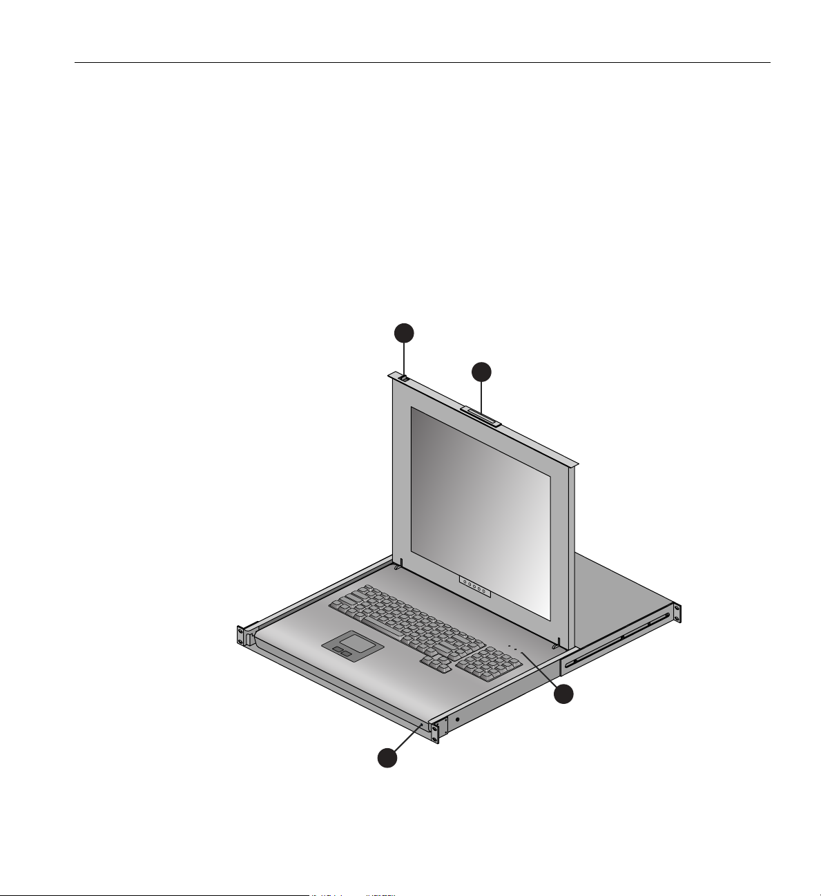
The flat panel console option (see Figure 1-1) has the following listed features:
1. Sl
when the console is not in use and prevents it from accidentally sliding open.
Console Connections
ide Release - Move this tab sideways to slide the console out. It locks the drawer closed
2. Ha
3. LCD
ndle - Used to push and pull the module in and out of the rack.
Display Controls - The LCD controls include On/Off buttons and buttons to control
the position and picture settings of the LCD display.
4. Power LED -
Illuminates blue when the unit is receiving power.
Figure 1-1 Flat Panel Rackmount Console Option
007-5806-004 3
Page 24
1: Operation Procedures
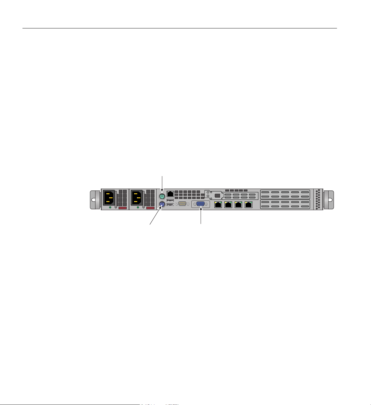
Mouse
Keyboard
VGA Port
A console is defined as a connection to the system (to the administrative server) that provides
administrative access to the cluster. SGI offers a rackmounted flat panel console option that
attaches to the administrative node’s video, keyboard and mouse connectors.
A console can also be a LAN-attached
personal computer, laptop or workstation (RJ45 Ethernet
connection). Serial-over-LAN is enabled by default on the administrative controller server and
normal output through the RS-232 port is disabled. In certain limited cases, a dumb (RS-232)
terminal could be used to communicate directly with the administrative server. This connection is
typically used for service purposes or for system console access in smaller systems, or where an
external ethernet connection is not used or available. Check with your service representative if use
of an RS-232 terminal is required for your system.
The flat panel rackmount or other optional VGA console connects to the administration
roller’s video and keyboard/mouse connectors as shown in Figure 1-2.
cont
Figure 1-2 Administrative Controller Video Console Connection Points
Powering the System On and Off
This section explains how to power on and power off individual rack units, or your entire
SGI ICE X system, as follows:
• “Preparing to Power On” on page 5
• “Powering On and Off” on page 8
Entering commands from a system console, you can power on and power off individual blade
sures, blade-based nodes, and stand-alone servers, or the entire system.
enclo
4 007-5806-004
Page 25
Preparing to Power On
Powering the System On and Off
When using the SGI cluster manager software, you can monitor and manage your server from a
remote location. See the SGI Management Center Administration Guide for Clusters,
(P/N 007-6358-00x) for more information.
To prepare to power on your system, follow these steps:
1. Check to ensure that the cabling between the rack’
s power distribution units (PDUs) and the
wall power-plug receptacle is secure.
2. For each individual blade enclosure pair
that you want to power on, make sure that the power
cables are plugged into all the blade enclosure power supplies correctly, see the example in
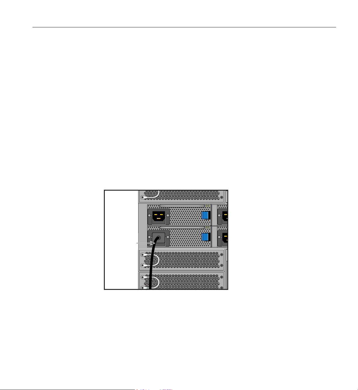
Figure 1-3. Setting the circuit breakers on the PDUs to t
the blade enclosure supplies and will
start each of the chassis managers in each enclosure.
he “On” position will apply power to
Note that the chassis managers in each blade enclosure stay powered on as long as there is
power coming into the unit. Turn off the PDU breaker switch that supplies voltage to the
enclosure pair if you want to remove all power from the unit.
Power cord
Figure 1-3 Blade Enclosure Power Supply Cable Example
3. If you plan to power on a server that includes optional mass storage enclosures, make sure
that the power switch on the rear of each PSU/cooling module (one or two per enclosure) is
1 (on) position.
in the
007-5806-004 5
Page 26
1: Operation Procedures
Power
distribution
unit (PDU)
Power
source
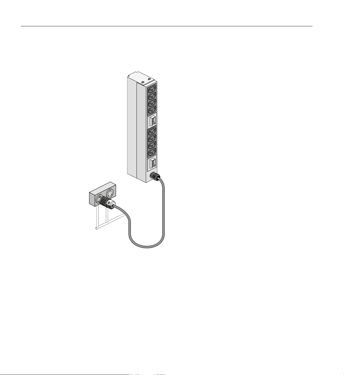
4. Make sure that all PDU circuit breaker switches (see the examples in Figure 1-4, and
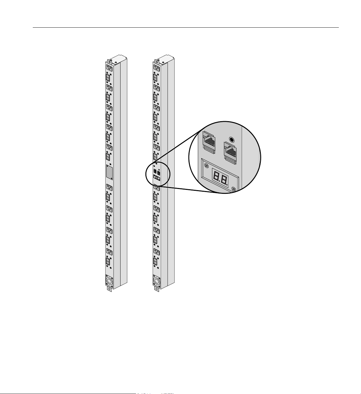
Figure 1-5 on page 7) are turned on to provide power when the system
is booted up.
Figure 1-4 Eight-Outlet Single-Phase PDU Example
Figure 1-5 on page 7 shows an example of the three-phase PDUs.
6 007-5806-004
Page 27
Powering the System On and Off
Figure 1-5 Three-Phase PDU Examples
007-5806-004 7
Page 28

1: Operation Procedures
Powering On and Off
The power-on and off procedure varies with your system setup. See the SGI Management Center
Administration Guide for Clusters, (P/N 007-6358-00x) for a more complete description of system
commands. The listed commands are supported with SMC 3.1 or later management software.
Note: The cpower commands are normally run through the administration node. If you have a
terminal connected to an administrative server with a serial interface, you should be able execute
these commands.
Console Management Power (cpower) Commands
This section provides an overview of the console management power (cpower) commands for
the SGI ICE X system.
The cpower commands allow you to power on, power off, reset, and show the power status of
multiple or single system components or individual racks.
The cpower command is, as follows:
cpower <option...> <target_type> <action> <target_list>
Example cpower command arguments are listed and described in Table 1-1. See Table 1-2 on
page 11 for examples of the cpower command strings.
Table 1-1 cpower option, action, target type and target list descriptions
Argument Description
Option
-h | --help Show this help message and then exit.
-w | --wait Wait for certain operations, (verification waiting timeout).
-i seconds |
--interval=seconds
-u | --no-umatched Unmatched target messages will be suppressed in the command output.
-v | --verbose Report command progress details and all errors.
8 007-5806-004
Specifies how long a target component’s LED will stay lit. This is valid with
the “identify” action (see the action descriptions). Specify a number of
seconds or use 0 to turn off the LED immediately. Also valid with reboot,
reset and on actions.
Page 29

Powering the System On and Off
Table 1-1 (continued) cpower option, action, target type and target list descriptions
Argument Description
Target_type
node Apply the action to a node or nodes. Nodes can be blade compute nodes
(inside a blade enclosure), administrative server nodes, rack leader controller
nodes or service nodes.
iru
Apply the action at the blade enclosure level. For the on and off
actions, the IRU’s switches and ICE compute blades are also targeted.
leader Applies the action to the rack leader nodes specified by target_list. Note that
accidental reset of an RLC could make a rack’s blade nodes unreachable.
system Apply the action to the entire system (with the exception of the admin node).
You must not specify a target with this type.
switch
Allows the target types to be InfiniBand switches and applies the action to
the blade switches specified by target_list.
Action
status Shows the power status of the target [default].
identify Turns on the identifying LED of the target for the period specified by the -i
seconds option (see the description in the Option portion of this table).
on
Powers on the target by sending an IPMI power-on command.Valid target
types are: switch, iru, leader, node and system.
If the target type is system, leaders and compute nodes are powered on
first; then, the ICE compute nodes are powered on.
off
Powers off the target by sending an IPMI power-off command.Valid target
types are: switch, iru, leader, node and system.
If the target type is system, ICE compute nodes are powered off first;
then, rack leaders are powered off. If the target type is iru, the associated
blade switches are also powered off. Initiates an automatic reboot of targets
upon completion of power-off sequence: use the halt action to stop this.
cycle
Power cycles the target by sending an IPMI cycle command.
Valid target types include leader, switch and node.
reboot Reboots the target via ssh reboot command, even if it is already booted.
Wait option (--wait) valid for leader and node targets to boot.
007-5806-004 9
Page 30

1: Operation Procedures
Table 1-1 (continued) cpower option, action, target type and target list descriptions
Argument Description
halt
reset
shutdown
Target_list
* Performs the listed action on all specified target types (such as "r1i*n*"
? Match exactly one character. Target list "r?i*n*" matches racks 1 through
[] The target list is any of the range of characters specified within brackets.
Halts and then powers-off the target(s). Halts the target by issuing a halt
command via ssh. Valid target types are: leader, node, system.
If the target type is system, ICE compute nodes are halted first; then, the
leaders are halted.
Performs a hard reset on the target by sending an IPMI reset
command. Valid target types are: leader and node.
The --wait option is available for this action.
Shuts down the target (but does not power it off) by sending a
shutdown -h now command via ssh. Waits for targets to shut down.
Valid target types are: node, leader and system.
which would affect all IRUs and nodes in rack one).
9 only.
A target list of "r1i2n[1-3]" would mean nodes 1 thru 3 in rack one,
IRU one.
The cpower target_list argument is required (except when the target_type is system). To ascertain
the names of targets, use the discover command and the cluster definition file as documented
in the SGI Management Center (SMC) Installation and Configuration Guide for Clusters (P/N
007-6359-00x).
10 007-5806-004
Page 31

Table 1-2 cpower example command strings
Command Status/result
Powering the System On and Off
# cpower system on
or
# cpower node on "r*i*n*"
# cpower node status "r1i*n*" Determines the power status of all nodes in rack
# cpower system status Provides status of every compute
# cpower node on "r1i*n*" Boots any nodes in rack 1 not already online.
# cpower system off
or
# cpower system halt
# cpower node halt "r*i*n*" Shuts down (halts) all the blade
# cpower system on Boots or reboots all rack leaders and nodes in a system.
# cpower node on r1i0n8 Command tries to specifically boot rack 1, IRU0, node 8.
# cpower leader status Determines the power status of all rack leaders.
# cpower node off "r
2i*n*" This command example issues an ipmi tool power-off
Powers on all nodes in the system.
1 (except
CMCs).
node in the system along
with all rack leaders.
Completely powers down ev
admin. If you are administering the system remotely through
the RLC it may become unreachable (see the next example).
the system, but not the administrative controller server, rack
leader controller or other service nodes.
command to all of the nodes in rack 2.
ery node in the system except the
enclosure compute nodes in
See the SGI Management Center Administration Guide for Clusters, (P/N 007-6358-00x) for more
information on cpower commands and related ipmi style commands.
See the section “System Power Status” on page 23 in this manual for additional related console
information.
007-5806-004 11
Page 32

1: Operation Procedures
Monitoring Your Server
You can monitor your SGI ICE X server from the following sources:
• An optional flat panel rackmounted monitor/keyboard can be connected to the
administration server node for basic monitoring and administration of the SGI ICE X
system. See the section
higher is required for this option.
• You can attach an optional LAN-connected console via secure shell (ssh) to an Ethernet port
adapter on the administration controller server. You will need to connect either a local or
remote workstation/PC to the IP address of the administration controller server to access and
monitor the system via IPMI.
See the SGI Management Center Administration Guide for Clusters, (P/N 007-6358-00x) for more
information on console management.
These console connections enable you to view the status and error messages generated by your
SGI ICE X system. You can also use these consoles to input commands to manage and monitor
your system. See the section
“Console Connections” on page 3 for more information. SLES 11 or
“System Power Status” on page 23, for additional information.
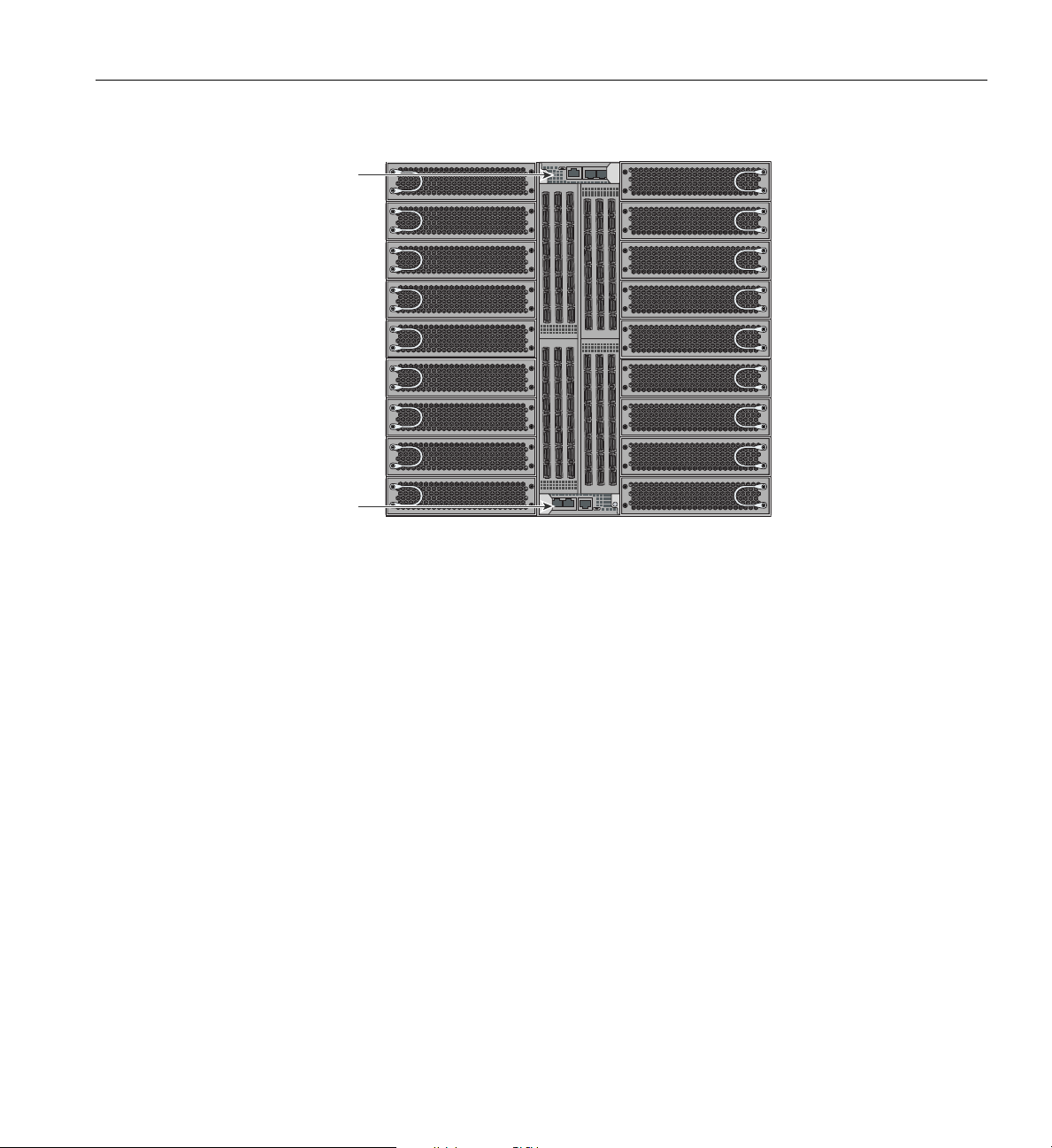
Figure 1-6 on page 13 shows an example of the CMC board front panel locations in a blade
enclosure. Note that a system using single-node ICE X blades will have one CMC board per blade
enclosure (installed in the lower position in the enclosure). An ICE X system using dual-node
blades must use two CMC boards.
See Figure 2-5 on page 23 for an example illustration of the connectors and indicators used on the
CMC board.
12 007-5806-004
Page 33
CMC-0 CMC-1 ACC
CNSL RES HB PG
CMC-0 CMC-1 ACC
CNSL RES HB PG
CMC 0
CMC 1
Optional SGI Remote Services (SGI RS)
Figure 1-6 Blade Enclosure Chassis Management Board Locations
The primary PCIe based I/O sub-systems are sited in the administrative controller server, rack
leader controller and service node systems used with the blade enclosures. These are the main
configurable I/O system interfaces for the SGI ICE X systems. See the particular server’s user
guide for detailed information on installing optional I/O cards or other components.
Note that each blade enclosure pair is configured with either
two or four InfiniBand switch blades.
Optional SGI Remote Services (SGI RS)
The optional SGI RS system automatically detects system conditions that indicate potential future
problems and then notifies the appropriate personnel. This enables you and SGI global support
teams to proactively support systems and resolve issues before they develop into actual failures.
SGI Remote Services provides a secure connection
can ensure business continuance with SGI systems management and optimization.
007-5806-004 13
to SGI Customer Support - on demand. This
Page 34

1: Operation Procedures
SGI Remote Services Primary Capabilities
• 24x7 remote monitoring and data gathering of SGI UV customer systems
• Alerts and notification on changes, failures and potential failures
• Log files immediately available
• Configuration fingerprint
• Secure file transfer
• Optional secure remote access to customer systems
SGI Remote Services Benefits
• Improved uptime and system availability
• Proactive identification of issues before they create an outage
• Increase system stability by monitoring hardware and software version compatibility
• Reduced time to resolve support cases
• Greater operational efficiency
• Less involvement of customer staff during troubleshooting
• Faster support case resolution
• Improved productivity
Proactive potential problem identification can result in higher system availability
Automated Alerts and, in some instances, Case Opening results in faster problem resolution time
and less direct involvement required by Customer Support Teams. SGI Remote Services are
available for all UV systems and also other specific SGI systems.
SGI Remote Service Operations Overview
An SGI Support Services Software Agent runs on each SGI system at your location, enabling
remote system monitoring and secure communication to SGI Support staff. Your basic hardware
and software configuration as well as system health information is captured and stored in the
Cloud.
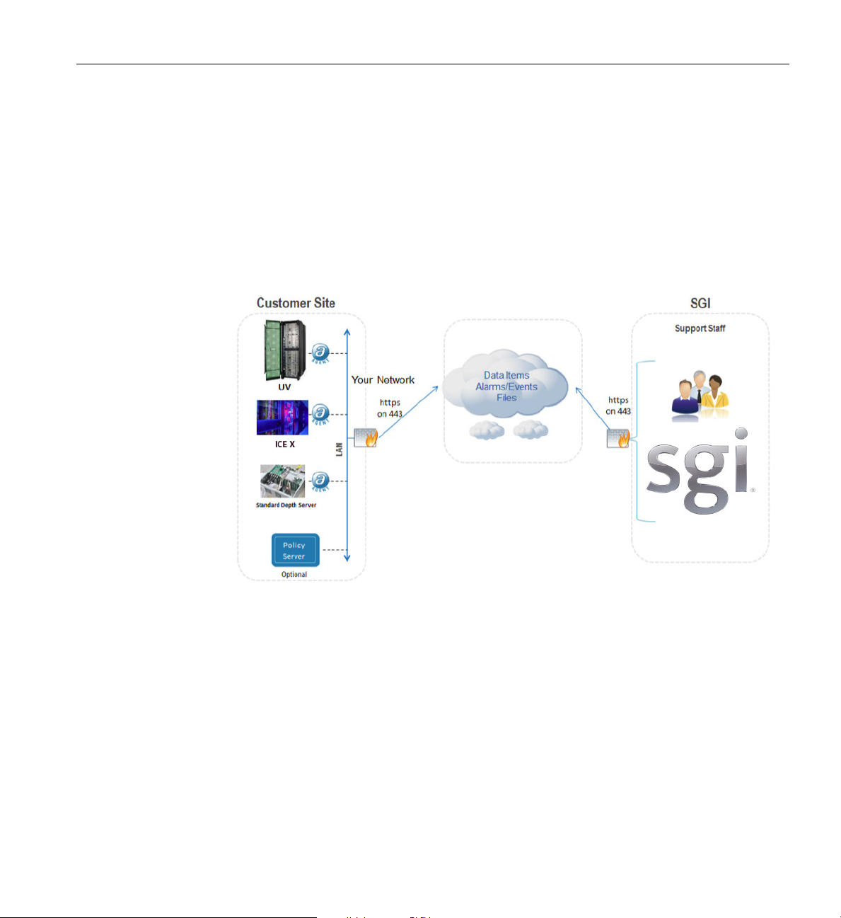
Figure 1-7 shows an example visual overview of the monitoring and response process.
14 007-5806-004
Page 35
Optional SGI Remote Services (SGI RS)
Cloud intelligence automatically reviews select Event Logs around the clock (every five minutes)
to identify potential failure information. If the Cloud intelligence detects a critical Event, it
notifies SGI support personnel.
This monitoring requires no changes to customer systems
or firewalls as long as the SGI Agent
can send HTTPS messages to highly secure Cloud and Global Access Servers. It will also have no
impact on customer network or system performance. All communication between SGI global
support and customer systems is kept secure using Secure Socket Layer (SSL) encryption. All
communication with SGI is initiated from the customer site using HTTPS protocol on port 443.
Figure 1-7 SGI Remote Services Process Overview
007-5806-004 15
Page 36

Page 37

Chapter 2
2. System Management
This chapter describes the interaction and functions of system controllers in the following
sections:
• “Levels of System and Chassis Control” on page 19
• “Chassis Manager Interconnects” on page 20
• “System Power Status” on page 23
One or two chassis management controllers (CMCs) are used in each blade enclosure. A single
CMC is used with single-node blades and two CMCs are needed when the enclosure uses
dual-node blades. The first CMC is located directly below the enclosure’s switch blade(s) and the
other directly above. The chassis manager supports power-up and power-down of the blade
enclosure’s compute node blades and environmental monitoring of all units within the enclosure.
Note that the stand-alone service nodes use IPMI to monitor system “health”.
Mass storage enclosures are not managed by the SGI ICE X system controller network.
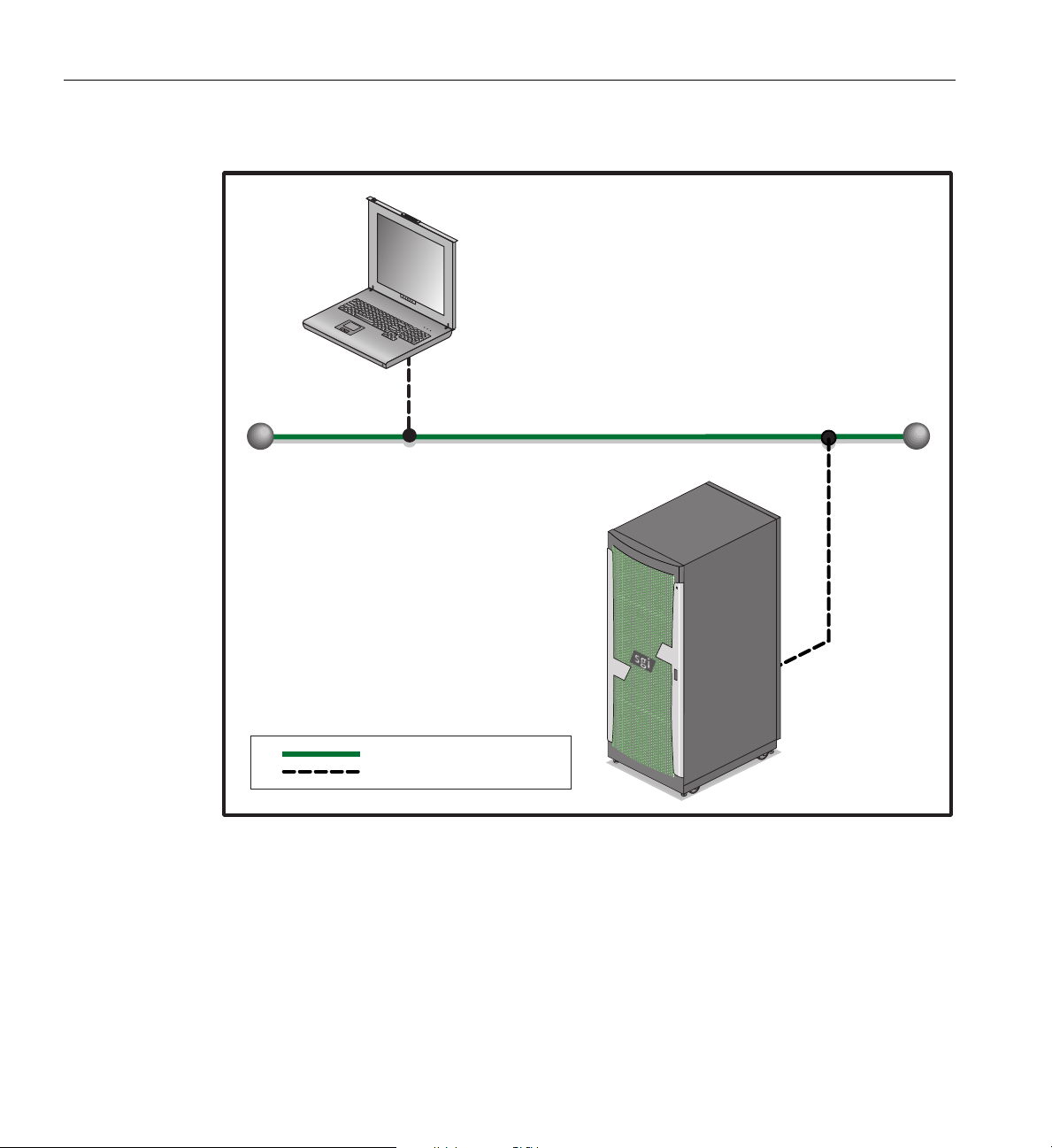
Figure 2-1 shows an example remote LAN-connected console used to monitor a single-rack
(D-rack) SGI ICE X series system.
007-5806-004 17
Page 38
2: System Management
Remote
workstation
monitor
Local Area Network (LAN)
SGI ICE X system
Local Area Network (LAN)
Cat-5 Ethernet
Figure 2-1 SGI ICE X System Network Access Example
18 007-5806-004
Page 39

Using the 1U Console Option
The SGI optional 1U console is a rack-mountable unit that includes a built-in keyboard/touch-pad,
and uses a 17-inch (43-cm) LCD flat panel display of up to 1280 x 1024 pixels. The 1U console
attaches to the administrative controller server connectors or to an optional KVM switch (not
provided standard by SGI). The 1U console is basically a “dumb” VGA terminal, it cannot be used
as a workstation or loaded with any system administration program.
Note: While the 1U console is normally plugged into the administrative controller server in the
SGI ICE X system, it can also be connected to a rack leader controller server in the system for
terminal access purposes.
The 27-pound (12.27-kg) console automatically goes into sleep mode when the cover is closed.
Levels of System and Chassis Control
The chassis management control network configuration of your ICE X series machine will depend
on the size of the system and the control options selected. Typically, any system with multiple
blade enclosures will be interconnected by the chassis managers in each blade enclosure.
Using the 1U Console Option
Note: Mass storage option enclosures are not monitored by the blade enclosure’s chassis manager.
Most optional mass storage enclosures have their own internal microcontrollers for monitoring
and controlling all elements of the disk array.
Chassis Controller Interaction
In all SGI ICE X series systems the system chassis management controllers communicate in the
following ways:
• All blade enclosures within a system are polled for and provide information to the
administrative node and RLC through their chassis management controllers (CMCs). Note
that the CMCs are enlarged for clarity in
• The CMC does the environmental management for each blade enclosure, as well as power
control, and provides an Ethernet network infrastructure for the management of the system.
007-5806-004 19
Figure 2-3.
Page 40
2: System Management
LAN1 LAN2 BMCLAN3 LAN4
LAN1 LAN2 BMCLAN3 LAN4
48-port
GigE switch
VLAN
VLAN
48-port
GigE switch
VLAN
VLAN
Stacking
cables
CMC-0
CMC-1
CMC-2
CMC-3
CMC-0
CMC-1
CMC-2
CMC-3
Rack 001 and 002 RLC
Customer
LAN
System admin node
Service node
LAN1 LAN2 BMC
Rack 001 Rack 002
= Link aggregation
Note: For an overview of how all the primary system components interact within the Ethernet
network infrastructure communicate, see the section “System Hierarchy” in Chapter 5.
Chassis Manager Interconnects
The chassis managers in each blade enclosure connect to the system administration, rack leader
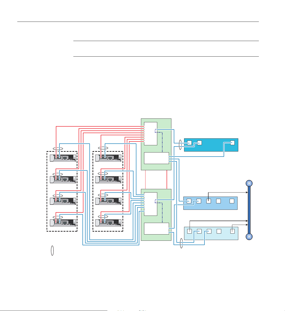
and service node servers via Gigabit Ethernet switches. See the redundant switch example in
Figure 2-2 and the non-redundant example in Figure 2-3 on page 21.
20 007-5806-004
Figure 2-2 Redundant Chassis Manager Interconnect Diagram Example
Page 41
Chassis Controller Interaction
LAN1 LAN2 BMC
LAN1 LAN2 BMC
CMC-0
CMC-1
CMC-2
CMC-3
CMC-0
CMC-1
CMC-2
CMC-3
48-port
GigE switch
Rack 001 and 002 RLC
VLAN
Customer
LAN
System admin node
Service node
LAN1 LAN2 BMC
Rack 001 Rack 002
VLAN
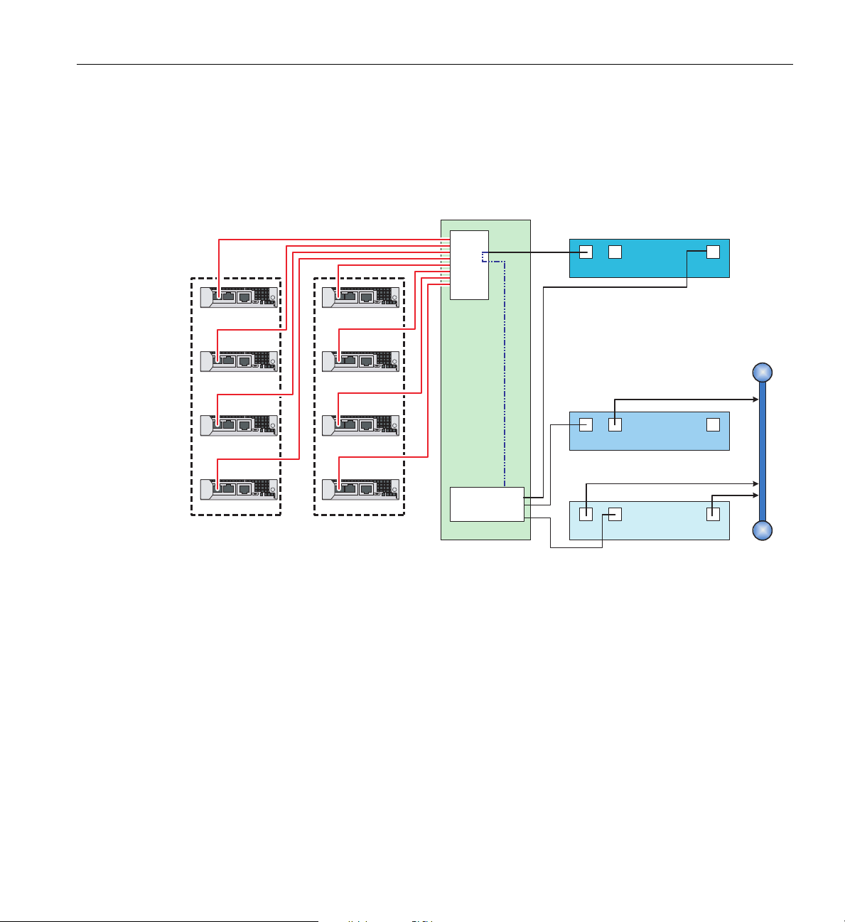
Note that the non-redundant example (shown in Figure 2-3) is a non-standard chassis management
configuration with only a single virtual
local area network (VLAN) connect line from each CMC
to the internal LAN switch. See also “Multiple Chassis Manager Connections” in Chapter 3.
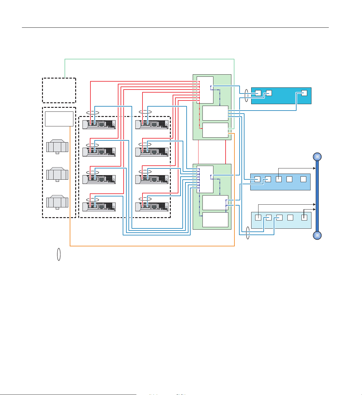
M-rack Chassis Manager Interconnection
007-5806-004 21
Figure 2-3 Non-redundant Chassis Manager Interconnection Diagram Example
The interconnection of an M-Cell’s rack environment is somewhat more complex than a D-rack
and requires the use of a third VLAN (VLAN3) within the Gigabit Ethernet switch network.
This VLAN3 interface allows the CM
Cs to monitor and adjust the activity of the cooling racks in
an M-cell as well as the external cooling distribution unit (CDU). The CDU rack supplies cooling
to the individual blades within the M-rack.
Figure 2-4 on page 22 shows a block diagram example of th
M-Cell rack.
e interconnection scheme for an
Page 42
48-port
GigE switch
48-port
GigE switch
Stacking
cables
VLAN
VLAN
VLAN
VLAN
VLAN
VLAN
LAN1 LAN2 BMCLAN3 LAN4
LAN1 LAN2 BMCLAN3 LAN4
CMC-0
CMC-1
CMC-2
CMC-3
CMC-4
CMC-5
CMC-6
CMC-7
M-rack RLC
Customer
LAN
System admin node
Service node
LAN1 LAN2 BMC
M-rack CMCs
= Link aggregation
M-Cell
cooling rack
Cooling
controller
Cooling
distribution
unit
2: System Management
Chassis Management Control (CMC) Functions
22 007-5806-004
Figure 2-4 M-rack System Chassis Manager Interconnect Example
The following list summarizes the control and monitoring functions that the CMCs perform. Most
functions are common across multiple blade enclosures:
• Controls and monitors blade enclosure fa
• Reads system identification (ID) PROMs
• Monitors voltage levels and reports failures
n speeds
Page 43
• Monitors the On/Off power sequence
CMC-0 CMC-1 ACC
CNSL RES HB PG
• Monitors system resets
• Applies a preset voltage to switch blades and fan control boards
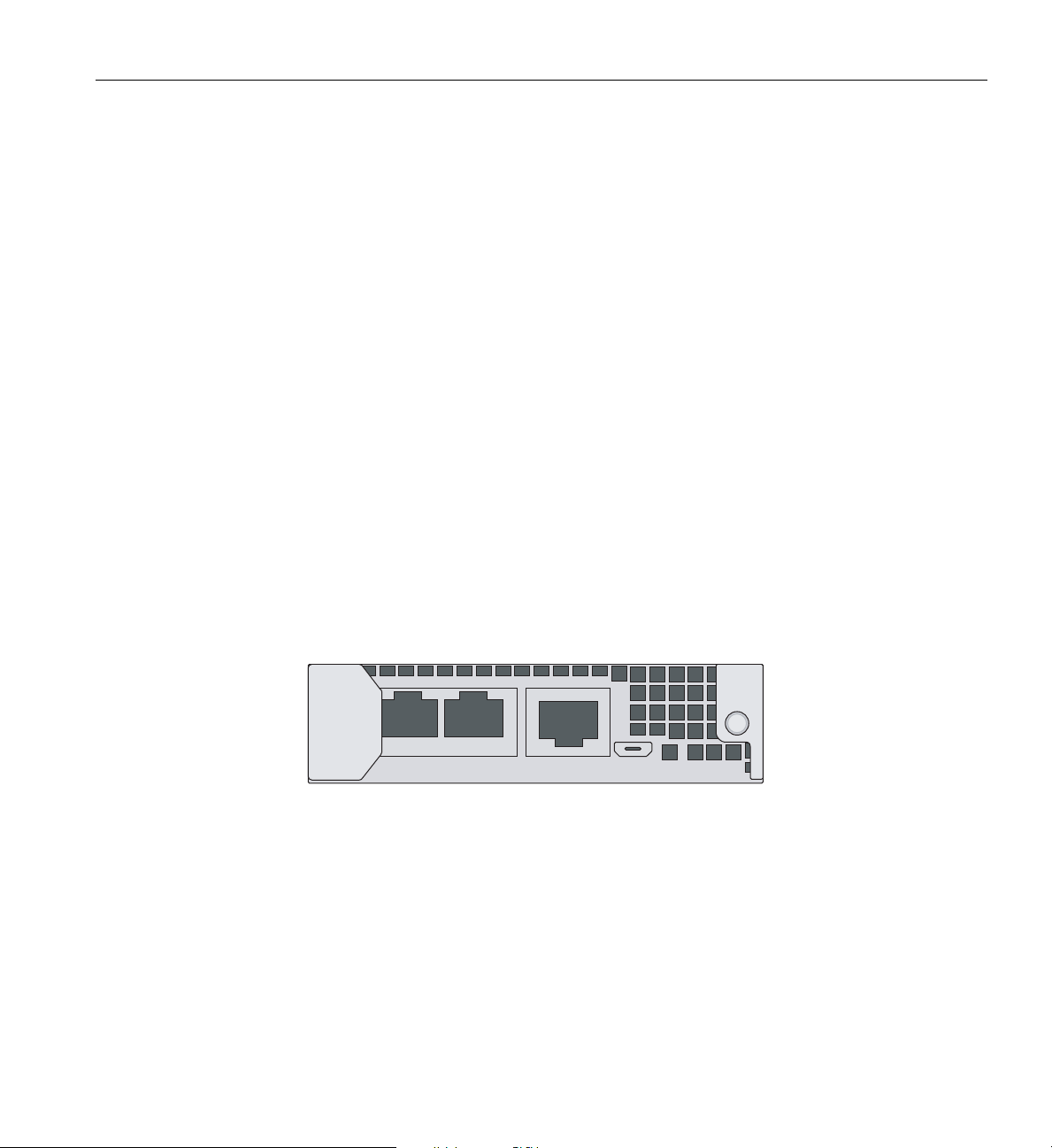
CMC Connector Ports and Indicators
The ports on the CMC board are used as follows:
System Power Status
• CMC-0 - Primary CMC connection, connects to th
e RLC via the 48-port management
switch
• CMC-1 - Secondary CMC connection to the RLC via the 48-port management switch (used
wit
h redundant VLAN switch configurations)
• ACC - Accessory port, used as a direct connection to the
microprocessor for service
• CNSL - Console connection - used primarily for service troubleshooting
• RES - RESET switch, depress this switch to reset the CMC microprocessor
• HB - Heartbeat LED, lighted green
LED indicates CMC is running
• PG - Power Good LED, this LED is illuminated green when power is present
Figure 2-5 shows the chassis management controller front panel in the blade enclosure.
Figure 2-5 Chassis Management Controller Board Front Panel Ports and Indicators
System Power Status
The cpower command is the main interface for all power management commands. You can
request power status and power-on or power-off the system with commands entered via the
administrative controller server or rack leader controller in the system rack. The cpower
007-5806-004 23
Page 44

2: System Management
commands are communicating with BMCs using the IPMI protocol. Note that the term “IRU”
represents a single blade enclosure within a blade enclosure pair.
The cpower command is the main interface for all power management commands. You can
request power status and power-on or power-off the system with commands entered via the
administrative controller server or rack leader controller in the system rack. The cpower
commands are communicating with BMCs using the IPMI protocol. Note that the term “IRU”
represents a single blade enclosure within a rack.
The system-level commands are applied first to service nodes, then to RLCs, then to blade
enclosures and compute blades.
The cpower commands may require several seconds to several minutes to complete, depending
on how many blade enclosures are being queried for status, powered-on, or turned off.
# cpower system status
This command gives the status of all compute nodes in the system.
To power on a specific blade enclosure, enter a command similar to the following:
# cpower iru on r1i0
In this example, the system should respond by powering on the IRU (blade enclosure) 0 nodes in
rack 1. Note that this command does not power-on the system administration (server) controller,
rack leader controller (RLC) server or other service nodes.
# cpower iru off r1i0
This command powers off all the nodes in IRU (blade enclosure) 0 in rack 1. Note that this
command does not power-off the system administration node (server), rack leader controller
server or other service nodes.
See “Console Management Power (cpower) Commands” on page 8 for additional information on
power-on, power-off and power status commands. The SGI Management Center Administration
Guide for Clusters, (P/N 007-6358-00x) has more extensive information on these topics.
24 007-5806-004
Page 45

Chapter 3
3. System Overview
This chapter provides an overview of the physical and architectural aspects of your SGI Integrated
Compute Environment (ICE) X series system. The major components of the SGI ICE X systems
are described and illustrated in the following sections:
• “System Models” on page 26
• “SGI ICE X System and Blade Architectures” on page 29
• “System Features and Major Components” on page 38
Because the system is modular, it combines the advantages of lower entry-level cost with global
scalability in processors, memory, InfiniBand connectivity and I/O. You can install and operate
the SGI ICE X series system in your lab or server room. Each 42U SGI rack holds one or two
21U-high (blade enclosure pairs). An enclosure pair is a sheetmetal assembly that consists of two
18-blade enclosures (upper and lower). The enclosures used in D-rack configurations are
separated by two “shelves.” In D-rack systems the shelves each hold three power supplies (shared
by the blade enclosures). In M-rack systems 1U shelves are used only to hold the blade enclosure
pairs and the power supplies are positioned on the sides of the blade enclosures. Each blade
enclosure also has an internal InfiniBand communication backplane. The 18 compute blades
supported in each enclosure can use one or two node boards, with ASICs, processors, memory
components and I/O chip sets mounted on them. The blades slide directly in and out of the
enclosures. Every compute node in a blade contains four or eight dual-inline memory module
(DIMM) memory units per processor socket. Optional hard disk or solid-state (SSD) drives and
MIC or GPU option boards are available. Each compute blade supports one or two individual node
boards. Note that a maximum system size of 72 compute blades per rack is supported at the time
this document was published. Optional chilled water cooling may be required for large
processor-count rack systems. Contact your SGI sales or service representative for the most
current information on these topics.
The SGI ICE X series systems can run parallel programs using a message passing tool like the
Message Passing Interface (MPI). The SGI ICE X blade system uses a distributed memory scheme
as opposed to a shared memory system like that used in the SGI UV series of high-performance
compute servers. Instead of passing pointers into a shared virtual address space, parallel processes
in an application pass messages and each process has its own dedicated processor and address
space.
007-5806-004 25
Page 46
3: System Overview
System Models
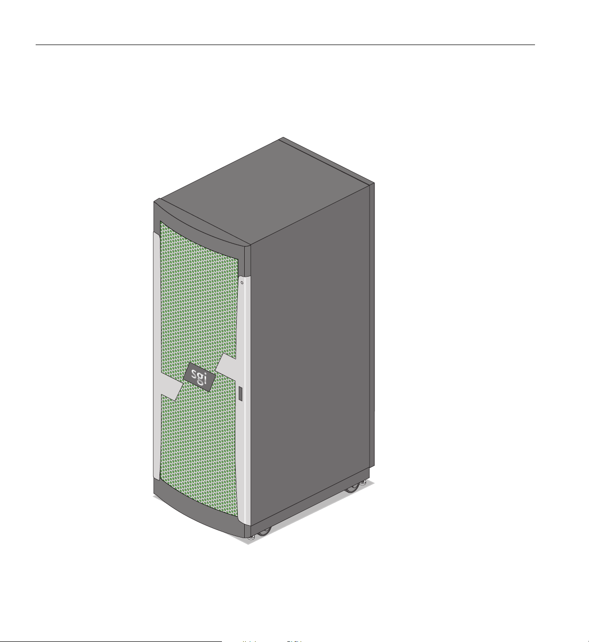
Figure 3-1 shows an example configuration of an air-cooled single-rack SGI ICE X server.
Figure 3-1 SGI ICE X Series System (Single Rack - Air Cooled Example)
26 007-5806-004
Page 47

System Models
The 42U rack for this server houses all blade enclosures, option modules, and other components;
up to 288 processors (4032 processor cores) in a single rack. The basic enclosure within the SGI
ICE X system is the 21U-high (36.75 inch or 93.35 cm) blade enclosure pair. The enclosure pair
supports a maximum of 36 compute blades, up to six power supplies, up to four chassis
management controllers (CMCs) and two or four InfiniBand based I/O fabric switch interface
blades. Note that two additional power supplies are used in an air-cooled enclosure pair and are
installed at the rear of the unit and dedicated to running the unit’s cooling fans (blowers).
Optional water chilled D-rack cooling is available. Note that systems with liquid-cooled blades
reside in M-Cell racks and always require water cooling systems to operate. See the section
Chapter 4, “Rack Information” for more information on water-cooled ICE X M-Cell systems.
The basic SGI ICE X system requires a minimum of one 42U tall rack with PDUs installed to
support each blade enclosure pair and any support servers or storage units. Each rack supports two
blade enclosure pairs.
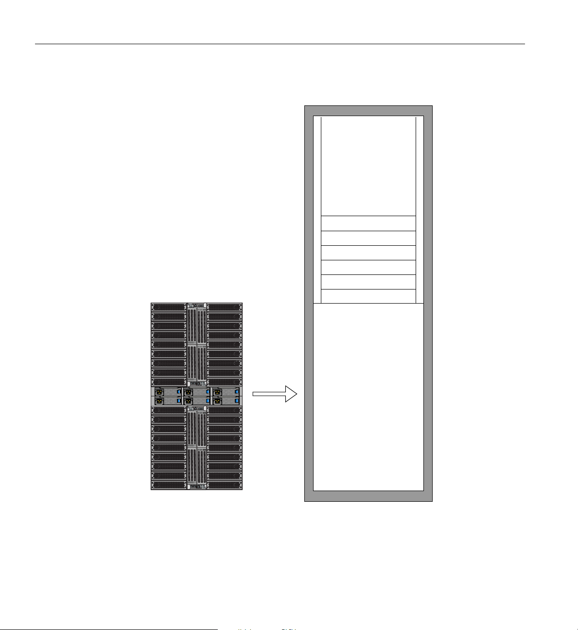
Figure 3-2 shows a blade enclosure pair and rack. The optional three-phase 208V PDU has nine
outlets and two PDUs are installed in each SGI ICE X compute rack. You can also add additional
RAID and non-RAID disk storage to your rack system and this should be factored into the number
of required outlets. An optional single-phase PDU has 8 outlets and can be used in an optional I/O
support rack.
007-5806-004 27
Page 48
42U High Rack
1U console
CMC-0 CMC-1 ACC CNSLRESHB PG
CMC-0 CMC-1 ACC CNSLRESHB PG
CMC-0 CMC-1 ACC CNSLRESHB PG
CMC-0 CMC-1 ACC CNSLRESHB PG
Blade enclosure pair
1U Gig-E switch
Blade enclosure
pair
1U Gig-E switch
Rack leader controller
Admin server
Service node
3: System Overview
Figure 3-2 D-rack Blade Enclosure and Rack Components Example
28 007-5806-004
Page 49

SGI ICE X System and Blade Architectures
The SGI ICE X series of computer systems are based on an FDR InfiniBand I/O fabric. This
concept is supported and enhanced by using the SGI ICE X blade-level technologies described in
the following subsections.
Depending on the configuration you ordered and your high-performance compute needs, your
system may be equipped with blades using a choice of one of three InfiniBand host-channel
adapter (HCA) cards, see
blade designs use only a specific host-channel adapter type.
IP113 Blade Architecture Overview
An enhanced and updated multi-core version of the SGI ICE compute blade is used in the ICE X
systems. The IP113 blade architecture is described in the following sections.
The compute blade contains the processors, memory, and one of the following fourteen-data rate
(FDR) InfiniBand imbedded HCA selections:
• One single-port IB HCA
“IP113 Blade Architecture Overview” for an example. Note that some
SGI ICE X System and Blade Architectures
• One dual-port IB HCA
• Two HCAs each with a single-port IB connector
The node board in an IP113 blade is configured with two multi-core Intel processors - a maximum
of 16 processor cores per compute blade were supported at the time this document was published.
A maximum of 16 DDR3 memory DIMMs are supported per compute blade.
The two processors on the IP113 maintain an interactive communication link using the Intel
QuickPath Interconnect (QPI) technology. This high-speed interconnect technology provides data
transfers between the on-board processors. See the section
page 34 for an overview of the link functionality and bandwidth capability. Note that the IP113
blade can optionally support one or two native “on-board” hard disk or SSD drive options for local
swap/scratch usage.
The IP113 compute blade cannot be plugged into and cannot be used in “previous generation” SGI
Altix ICE 8200 or 8400 series blade enclosures. Multi-generational system interconnects can be
made through the InfiniBand fabric level. Check with your SGI service or sales representative for
additional information on these topics.
007-5806-004 29
“QuickPath Interconnect Features” on
Page 50

3: System Overview
IP115 Blade Architecture Overview
An enhanced and updated multi-core version of the SGI ICE compute blade is used in specific
versions of the ICE X systems. The IP115 blade architecture is described in the following sections.
Two dual-socket node boards are installed in each blade. Each node board in the blade contains
the processors, memory, and the following fourteen-data rate (FDR) InfiniBand imbedded HCA:
• Two HCAs each with a single-port IB connector
Each of the two node boards inside the compute blade is configured with two multi-core Intel
processors - a maximum of 32 processor cores per compute blade at the time this document was
published. Note that the two node boards within the blade are logically independent. Each
processor assembly uses a liquid-cooled “cold-sink” to draw off heat from the CPU.
Note: In a blade enclosure-pair using IP115 nodes, all four switch blades must be present, as two
switch blades are required for each enclosure. This configuration supports a single-plane topology
in each of the blade enclosures.
A maximum of 16 DDR3 memory DIMMs are supported per compute blade (8 on each node
board). The DIMM slots support up to 1600 MT/s DIMMs.
Each node board in the IP115 blade assembly supports one optional 2.5-inch hard disk drive or
solid state drive (SSD).
The two processors on each node board in the IP115 blade maintain an interactive communication
link using the Intel QuickPath Interconnect (QPI) technology. This high-speed interconnect
technology provides data transfers between the on-board processors. See the section
“QuickPath
Interconnect Features” on page 34 for an overview of the link functionality and bandwidth
capability.
The IP115 compute blade cannot be plugged into and cannot be used in “previous generation” SGI
Altix ICE 8200 or 8400 series blade enclosures. Usage in third-party or non SGI ICE X racks may
be restricted due to thermal requirements.
Multi-generational system interconnects can be made through the InfiniBand fabric level. Check
with your SGI service or sales representative for additional information on these topics.
30 007-5806-004
Page 51

IP119 Blade Architecture Overview
An enhanced and updated multi-core version of the SGI ICE compute blade is used in specific
versions of the ICE X systems. The IP119 blade architecture is described in the following sections:
The compute blade contains the interleaved base and mezzanine node boards, processors,
co-processors, memory, optional HDD or SSD and one of the following fourteen-data rate (FDR)
InfiniBand embedded HCA selections:
• One single-port IB HCA
• One dual-port IB HCA
• Two HCAs each with a single-port IB connector
The dual-socket node inside the compute blade is made up of a base and mezzanine board and has
the following features:
• Each of the two boards within the blade supports one Xeon E5-2600 processor assembly and
one Intel Xeon Phi co-processor
• A PCIe link connects the base and mezzanine boards
• Processors and co-processors are cooled with liquid “Cold Sink” technology
SGI ICE X System and Blade Architectures
• Four RDDR3 memory DIMM slots per board support up to 1600 MT/s DIMMs (eight
memory DIMM slots total within the blade)
• One 2.5” HDD or 2.5” SSD per blade assembly
• Board management controller (BMC)
The IP119 compute blade cannot be plugged into and cannot be used in “previous generation” SGI
Altix ICE 8200 or 8400 series blade enclosures. Usage in third-party or non SGI ICE X racks may
be restricted due to thermal requirements.
Multi-generational system interconnects can be made through the InfiniBand fabric level. Check
with your SGI service or sales representative for additional information on these topics.
See the section “QuickPath Interconnect Features” on page 34 for an overview of that link
functionality and bandwidth capability.
007-5806-004 31
Page 52

3: System Overview
IP131 Blade Architecture Overview
An enhanced and updated version of the SGI ICE X compute blade is used in IP131-based ICE X
systems. One dual-socket node is accommodated on each IP131 blade assembly. The IP131 blade
architecture is described in the following paragraphs:
The compute blade contains the processors, memory, and one of the following fourteen-data rate
(FDR) InfiniBand embedded HCA selections:
• One single-port IB HCA
• One dual-port IB HCA
• Two HCAs each with a single-port IB connector
The node board in an IP131 blade is configured with two Intel E5 2600 v3 processors.
Processor core counts will differ on individual blades based on processing requirements. Check
with your SGI sales representative for processor core counts that meet your compute needs.
A maximum of 16 DDR4 memory DIMMs are supported per compute blade (8 DIMMs per
socket).
The two processors on the IP131 maintain an interactive communication link using the Intel
QuickPath Interconnect (QPI) technology. This high-speed interconnect technology provides data
transfers between the on-board processors. See the section
“QuickPath Interconnect Features” on
page 34 for an overview of the link functionality and bandwidth capability. Note that the IP131
blade can optionally support one or two native “on-board” 2.5-inch SATA hard disk or SSD drive
options for local swap/scratch usage.
The IP131 node board uses traditional air-cooled heat sinks and works in an air-cooled
environment. The IP131 compute blade cannot be plugged into and cannot be used in “previous
generation” SGI Altix ICE 8200 or 8400 series blade enclosures.
Multi-generational system interconnects can be made through the InfiniBand fabric level.
Note that usage in third-party or non SGI ICE X racks may be restricted due to thermal
requirements.
Check with your SGI service or sales representative for additional information on these topics.
32 007-5806-004
Page 53

IP133 Blade Architecture Overview
An enhanced and updated dual-node SGI ICE X (IP133) compute blade is used in specific
versions of the ICE X systems. The IP133 blade architecture is described in the following sections.
Two dual-socket node boards are installed in each IP 133 blade. Each node board in the blade
contains the processors, memory, and the following fourteen-data rate (FDR) InfiniBand
embedded HCA:
• Two HCAs each with a single-port IB connector
Each of the two node boards inside the compute blade is configured with two Intel processors - a
maximum of four processors per compute blade. Note that the two node boards within the blade
are logically independent. Each processor assembly uses a liquid-cooled “cold-sink” to draw off
heat from the CPU. Processor core counts will differ on individual blades based on processing
requirements. Check with your SGI sales representative for processor core counts that meet your
compute needs.
Note: In a blade enclosure-pair using IP133 nodes, all four switch blades must be present, as two
switch blades are required for each enclosure. This configuration supports a single-plane topology
in each of the blade enclosures.
SGI ICE X System and Blade Architectures
A maximum of 16 DDR4 memory DIMMs are supported per compute blade (8 on each node
board). The DIMM slots support up to 2133 MT/s DIMMs.
Each node board in the IP133 blade assembly supports one optional 2.5-inch hard disk drive or
one optional solid state drive (SSD).
The two processors on each node board in the IP133 blade maintain an interactive communication
link using the Intel QuickPath Interconnect (QPI) technology. This high-speed interconnect
technology provides data transfers between the on-board processors. See the section
“QuickPath
Interconnect Features” on page 34 for an overview of link functionality and bandwidth capability.
The IP133 compute blade assembly cannot be plugged into and cannot be used in “previous
generation” SGI Altix ICE 8200 or 8400 series blade enclosures. The IP133 is a custom
liquid-cooled blade and usage in third-party or non SGI ICE X racks is unsupported at the time
this document was published. Multi-generational system interconnects can be made through the
InfiniBand fabric level. Check with your SGI service or sales representative for additional
information on these topics.
007-5806-004 33
Page 54

3: System Overview
QuickPath Interconnect Features
Each processor socket on an ICE X system node board is interconnected using two QuickPath
Interconnect (QPI) links. Each QPI link consists of two point-to-point 20-bit channels - one send
channel and one receive channel. Each QPI channel is capable of sending and receiving at the
same time – on the same 20 bit channel. The QPI link has a theoretical maximum aggregate
bandwidth of 25.6 GB/s using a 3.2 GHz clock rate and 38.4 GB/s using a 4.8 GHz clock rate.
Each blade’s I/O chip set supports two processors.
IP113, IP115 and IP119 QPI Bandwidth
The maximum bandwidth of a single QPI link used in the IP113, IP115 or IP119 node board is
calculated as follows:
• The QPI channel uses a 3.2 GHz clock, but the effective clock rate is 6.4 GHz because two
bits are transmitted at each clock period - once on the rising edge of the clock and once on
the falling edge (DDR).
• Of the 20 bits in the channel, 16 bits are data and 4 bits are error correction.
• 6.4 GHz times 16 bits equals 102.4 Gbits per second.
• Convert to bytes: 102.4 divided by 8 equals 12.8 GB/s (max single direction bandwidth)
• The total aggregate bandwidth of the QPI channel is 25.6 GB/s: (12.8 GB/s x 2 channels)
IP131 and IP133 QPI Bandwidth
The maximum bandwidth of a single QPI link used in the IP131 or IP133 node board is calculated
as follows:
• The QPI channel uses a 4.8 GHz clock, but the effective clock rate is 9.6 GHz because two
bits are transmitted at each clock period - once on the rising edge of the clock and once on
the falling edge (DDR).
• Of the 20 bits in the channel, 16 bits are data and 4 bits are error correction.
• 9.6 GHz times 16 bits equals 153.6 Gbits per second.
• Convert to bytes: 153.6 divided by 8 equals 19.2 GB/s (max single direction bandwidth)
• The total aggregate bandwidth of the QPI channel is 38.4 GB/s: (19.2 GB/s x 2 channels)
34 007-5806-004
Page 55

Blade Memory Features
The memory control circuitry is integrated into the processors and provides greater memory
bandwidth and capacity than previous generations of ICE compute blades. Note that the IP131 and
IP133 blades use DDR4 DIMMs, while IP113, IP115 and IP119 use DDR3 DIMM technology.
Blade DIMM Memory Features
Note that each Intel processor on an ICE X IP113, IP115 or IP119 node board uses four DDR3
memory channels with one or more memory DIMMs on each channel (depending on the
configuration selected). Each of these blades can support up to 16 DIMMs. The DDR3 memory
channel supports a maximum memory bandwidth of up to 12.8 GBs per second. The combined
maximum bandwidth for all DDR3 memory channels on a single processor is 51.2 GBs per
second.
The IP131 compute blade supports a maximum of sixteen DDR4 RDIMMs. Memory increments
are in groups of 4 DIMMs. A maximum of sixteen DDR4 memory DIMMs are supported on each
IP131 blade. The IP133 compute blade uses two separate and independent node boards and each
node supports a maximum of eight DDR4 memory DIMMs.
QuickPath Interconnect Features
Each E5 2600 v3 processor used on IP131 and IP133 blades has four DDR4 memory channels for
a total of eight DIMMs per processor socket. Each memory channel supports a maximum of two
memory DIMMs for a total of eight DIMMs per processor. The peak transfer rates for one DDR4
channel is 17.06 GB/s (2133 x 8). The combined peak total of all four channels on a single
processor is 68.25 GB/s (17.06 x 4).
Memory Channel Recommendation
It is highly recommended (though not required) that each processor on a system node board be
configured with a minimum of one DIMM for each memory channel on a processor. This will help
to ensure the best DIMM data throughput.
Blade DIMM Bandwidth Factors
The memory bandwidth on node boards within SGI ICE X blades is generally determined by the
following key factors:
• The processor speed - different processor SKUs support different DIMM speeds.
• The processor’s support for DDR3 or DDR4 DIMM technology.
007-5806-004 35
Page 56

3: System Overview
• The number of DIMMs per channel.
• The DIMM speed - the DIMM itself has a maximum operating frequency or speed, such as
2133 MT/s or 1600 MT/s.
Note: A DIMM must be rated for the maximum speed to be able to run at the maximum
speed. For example: a single 1600 MT/s DIMM on a channel will only operate at speeds up
to 1600 MT/s - not 2133 MT/s.
Populating one 1600 MT/s DIMM on each channel of an ICE X system blade node board delivers
a maximum of 12.8 GB/s per channel or 51.2 GB/s total memory bandwidth.
A minimum of one dual-inline-memory module (DIMM) is required for each processor on a node
board; four DIMMs per processor are recommended. Each of the DIMMs on a blade’s node board
must be the same capacity and functional speed. When possible, it is generally recommended that
all blade node boards within an enclosure use the same number and capacity (size) DIMMs.
Each blade in the enclosure pair may have a different total DIMM capacity. For example, one
blade may have 16 DIMMs, and another may have only eight. Note that while this difference in
capacity is acceptable functionally, it may have an impact on compute “load balancing” within the
system.
System InfiniBand Switch Blades
Two or four fourteen-data-rate (FDR) InfiniBand switch blades can be used with each blade
enclosure pair configured in the SGI ICE X system. Single-node blade enclosure pairs use two
switch blades for single-plane InfiniBand topologies. Enclosure pairs with four switch blades
(using single-node blades) use a dual-plane topology that provides high-bandwidth
communication between compute blades inside the enclosure as well as blades in other enclosures.
Enclosure pairs using dual-node compute blades (such as the IP115 or IP133) must use four switch
blades to support a single-plane InfiniBand topology.
Enclosure Switch Density Choices
Each SGI ICE X system comes with a choice of two switch blade configurations.
• Single 36-port FDR IB ASIC (standard) with 18 external ports per switch
• Dual 36-port FDR IB ASIC (premium) with a total of 48 external ports per switch
36 007-5806-004
Page 57
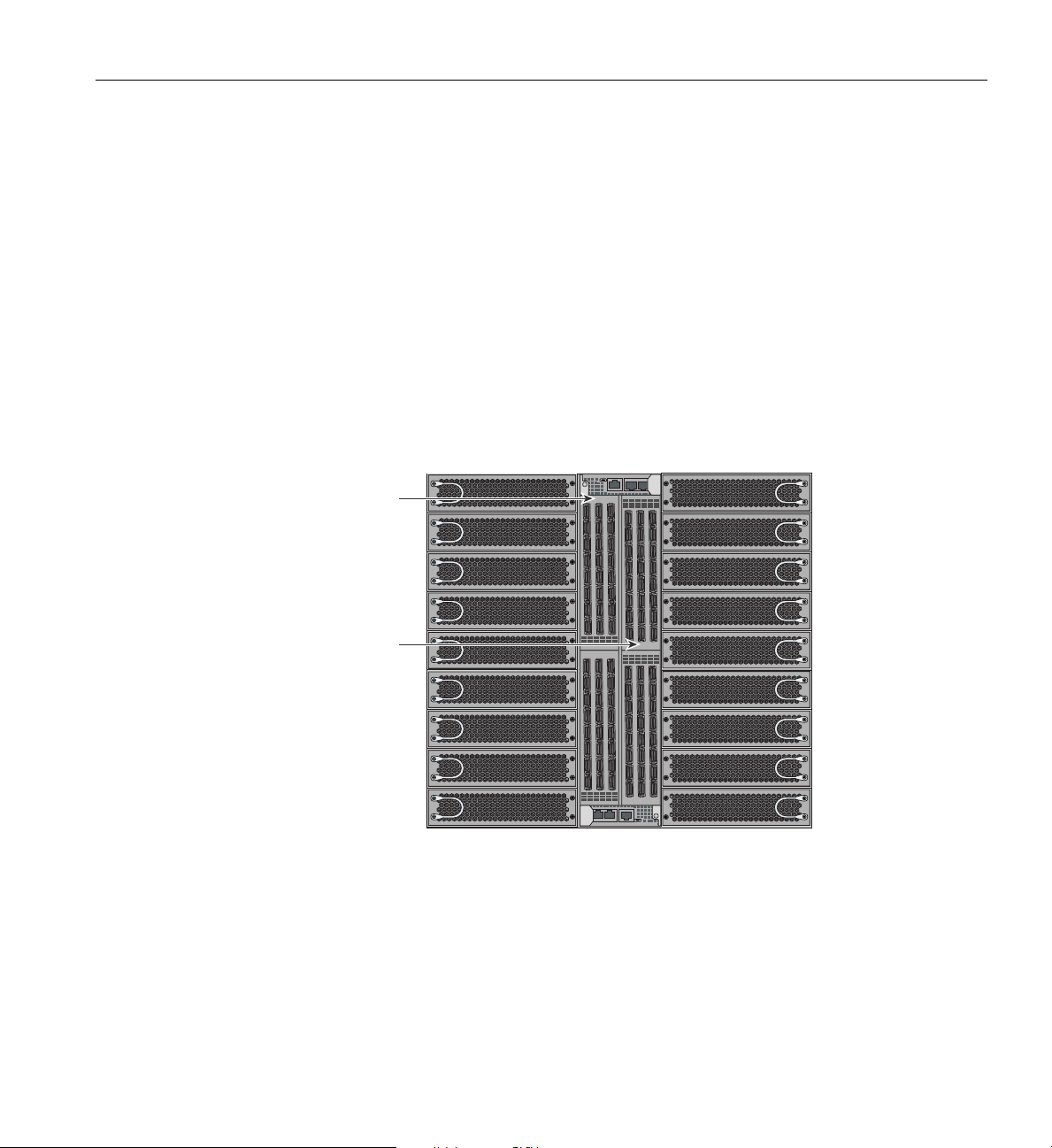
QuickPath Interconnect Features
CMC-0 CMC-1 ACC
CNSL RES HB PG
CMC-0 CMC-1 ACC
CNSL RES HB PG
Switch blade 1
Switch blade 0
The single-switch ASIC and dual-switch ASIC switch blades for each enclosure pair are not
interchangeable without re-configuration of the system. The outward appearance of the two types
is very similar, but differs in regards to the number and location of QSFP ports.
Enclosures using one or two FDR switch blades are
available in certain specific configurations. A
single-switch blade within a blade enclosure supports a single-plane FDR InfiniBand topology
only when configured with a single-node blade such as the IP113 or IP131. A blade-enclosure pair
using dual-node blades must use four switch blades to support a single-plane topology. Check with
your SGI sales or service representative for additional information on availability.
The SGI ICE X FDR switch blade locations example is
shown in Figure 3-3 on page 37. Any
external switch blade ports not used to support the IB system fabric may be connected to optional
ce nodes or InfiniBand mass storage. Check with your SGI sales or service representative for
servi
information on available options.
Figure 3-3 InfiniBand 48-port (Premium) FDR Switch Numbering in Blade Enclosures
007-5806-004 37
Page 58

3: System Overview
System Features and Major Components
The main features of the SGI ICE X series server systems are introduced in the following sections:
• “Modularity and Scalability” on page 38
• “Reliability, Availability, and Serviceability (RAS)” on page 45
Modularity and Scalability
The SGI ICE X series systems are modular, blade-based, scalable, high-density cluster systems.
The system rack components are primarily housed in building blocks referred to as blade
enclosure pairs. Each enclosure pair consists of a sheet-metal housing with internal IB backplanes
and six (shared) power supplies that serve two “blade enclosures”.
However, other “free-standing” SGI compute servers are used to administer, access and service
the SGI ICE X series systems. Additional optional mass storage may be added to the system along
with additional blade enclosures. You can add different types of stand-alone module options to a
system rack to achieve the desired system configuration. You can configure and scale blade
enclosures around processing capability, memory size or InfiniBand fabric I/O capability. The
air-cooled blade enclosure has redundant, hot-swap fans and redundant, hot-swap power supplies.
A water-chilled rack option expands an ICE X rack’s heat dissipation capability for the blade
enclosure components without requiring lower ambient temperatures in the lab or server room.
See
Figure 4-3 on page 59 for an example water-chilled D-rack.
A number of free-standing (non-blade) compute and I/O servers (also referred to as nodes) are
used with SGI ICE X series systems in addition to the standard two-socket blade-based compute
nodes. These free-standing units are:
• System administration controller
• System rack leader controller (RLC) server
• Service nodes with the following functions:
– Fabric management service node
– Login node
– Batch node
– I/O gateway node
– MDS or OSS nodes (used in optional Lustre configurations)
38 007-5806-004
Page 59
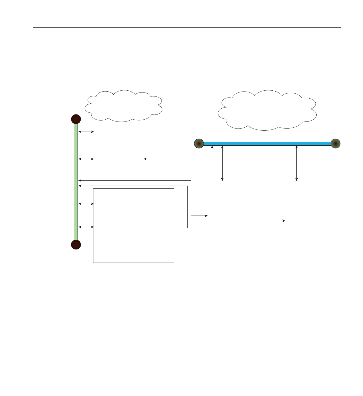
System Features and Major Components
ICE X
System Management
Network
ICE X
System Computation
Network
FDR InfiniBand Network
GigE Management Network
System Admin Node
One per system
Runs Linux OS
Runs SGI Management Center
Rack Leader Controllers
One per logical rack
Runs Linux OS
Runs IB Fabric Manager
Out-of-Band Software
CMC = Chassis Management Controller
Located in all blade enclosure chassis
Runs IPMI software (eRIC)
BMC = Board Management Controller
Located in:
All compute blades
Admin controller
All Rack Leader Controllers
All service nodes
Runs IPMI software
Compute Blades
Contains the following:
Processors
Memory
Optional PCIe slots and drives
Optional MIC/GPU cards
Each Blade has a BMC
Runs Linux OS
Service Nodes
Login
Batch
Gateway
Optional Lustre Nodes
Storage
Runs Linux OS
Each node has a BMC
In-Band Software
Each SGI ICE X system will have one system administration controller, at least one rack leader
controller (RLC) and at least one service node. All ICE X systems require one RLC for every eight
CMCs in the system. Figure 3-4 shows an overview of the SGI ICE X system management and
component network interaction.
System Administration Server
007-5806-004 39
Figure 3-4 SGI ICE X System and Network Components Overview
The administration server and the RLCs are integrated stand-alone 1U servers. The service nodes
are integrated stand-alone non-blade 1U or 2U servers. The following subsections further define
the free-standing server unit functions described in the previous list.
There is a minimum of one stand-alone administration controller server and I/O unit per system.
The system administration controller is a non-blade SGI 1U server system (node). Note that a
high-availability administration server configuration is available that doubles the number of
Page 60

3: System Overview
Rack Leader Controller
administrative servers used in a system. In high-availability (HA) administration server
configurations, two servers are paired together. The primary admin server is backed up by an
identical “backup” admin server. The second (backup) server runs the same system management
image as the primary server.
The server is used to install SGI ICE X system software, administer that software and monitor
information from all the compute blades in the system. Check with your SGI sales or service
representative for information on “cold spare” options that provide a standby administration
server on site for use in case of failure.
The administration server on ICE X systems is connected to the external network. All ICE X
systems are configured with dedicated “login” servers for multiple access accounts. You can
configure multiple “service nodes” and have all but one devoted to interactive logins as “login
nodes”, see the
“Login Server Function” on page 42 and the “I/O Gateway Node” on page 43.
A rack leader controller (RLC) server is generally used by administrators to provision and manage
the system using SGI’s cluster management (CM) software. One rack leader controller is required
for every eight CMC boards used in a system and it is a non-blade “stand-alone” 1U server. The
rack leader controllers are guided and monitored by the system administration server. Each RLC
in turn monitors, pulls and stores data from all the blade enclosures within the logical rack that it
monitors. The rack leader then consolidates and forwards data requests received from the blade
enclosures to the administration server. A rack leader controller also supplies boot and root file
sharing images to the compute nodes in the enclosures.
Note that a high-availability RLC configuration is available that doubles the number of RLCs used
in a system. In high-availability (HA) RLC configurations, two RLCs are paired together. The
primary RLC is backed up by an identical “backup” RLC server. The second (backup) RLC runs
the same fabric management image as the primary RLC. Check with your SGI sales or support
representative for configurations that use a “spare” RLC or administration server. This option can
provide rapid “fail-over” replacement for a failed RLC or administrative unit.
Multiple Chassis Manager Connections
In multiple-rack configurations the chassis managers (up to eight CMCs) may be interconnected
to the rack leader controller (RLC) server via one or two Ethernet switches.
Figure 3-5 shows an
example diagram of the CMC interconnects between two ICE X system racks using a virtual local
area network (VLAN). This example is not applicable to M-Cell closed-loop systems. For more
information on these and other topics related to the CMC, see the SGI Management Center
40 007-5806-004
Page 61
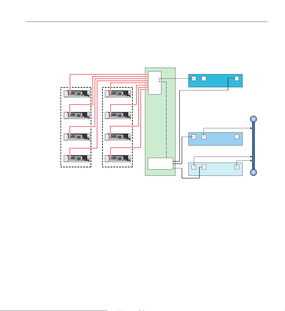
System Features and Major Components
LAN1 LAN2 BMC
LAN1 LAN2 BMC
CMC-0
CMC-1
CMC-2
CMC-3
CMC-0
CMC-1
CMC-2
CMC-3
48-port
GigE switch
Rack 001 and 002 RLC
VLAN
Customer
LAN
System admin node
Service node
LAN1 LAN2 BMC
Rack 001 Rack 002
VLAN
Administration Guide for Clusters, (P/N 007-6358-00x). Note also that the scale of the CMC
drawings in Figure 3-5 is adjusted to clarify the interconnect locations.
The RLC as Fabric Manager
007-5806-004 41
Figure 3-5 D-Rack Administration and RLC Cabling to CMCs Example
In some SGI ICE X configurations the fabric management function is handled by the rack leader
controller (RLC) node. The RLC is an independent server that is not part of the blade enclosure
pair.
See the “Rack Leader Controller” on page 40 subsection for more detail. The fabric management
software runs on one or two RLC nodes and monitors th
e function of and any changes in the
InfiniBand fabrics of the system. It is also possible to host the fabric management function on a
dedicated service node, thereby moving the fabric management function from the rack leader node
and hosting it on an additional server(s). A separate fabric management server would supply fabric
status information to the system’s administration server periodically or upon request.
Page 62
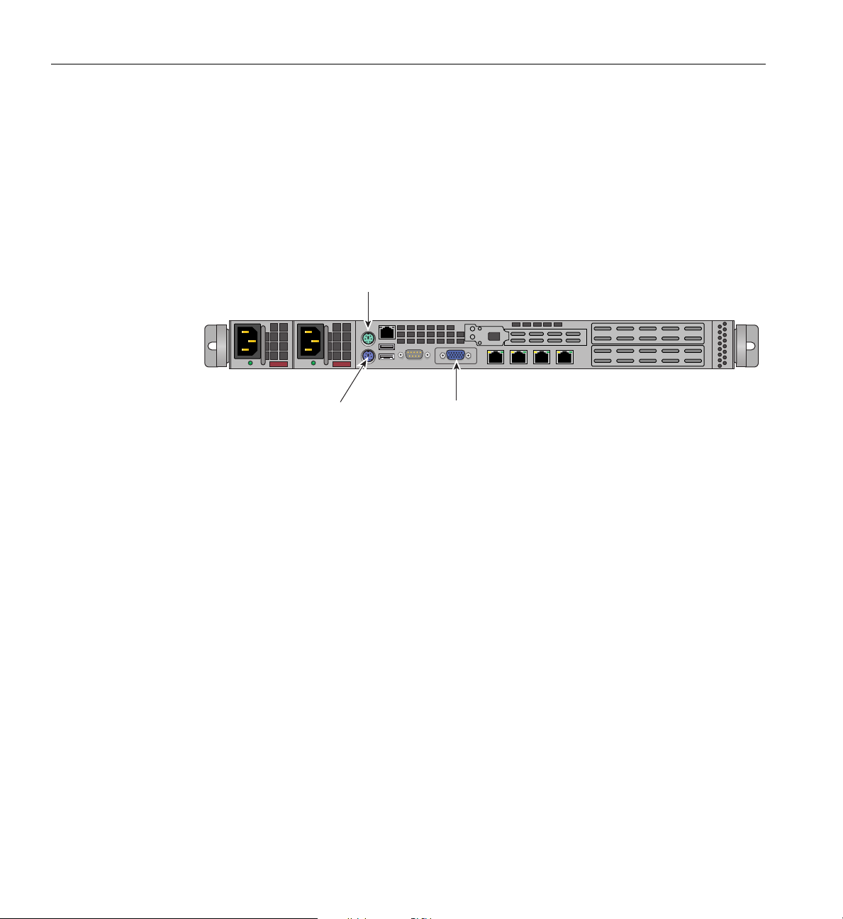
3: System Overview
Mouse
Keyboard
VGA Port
Service Nodes
The functionality of the service “nodes” listed in this subsection are all services that can
technically be shared on a single hardware server unit. System scale, configuration and number of
users generally determines when you add more servers (nodes) and dedicate them to these service
functions. However, you can also have a smaller system where several of the services are
combined on just a single service node. Figure 3-6 shows an example rear view of a 1U service
node. Note that dedicated fabric management nodes
Figure 3-6 Example Rear View of a 1U Service Node
are recommended on 8-rack or larger systems.
Login Server Function
The login server function within the ICE system can be functionally combined with the I/O
gateway server node function in some configurations. One or more per system are supported. Very
large systems with high levels of user logins may use multiple dedicated login server nodes. The
login node functionality is generally used to create and compile programs, and additional login
server nodes can be added as the total number of user logins increase. The login server is usually
the point of submittal for all message passing interface (MPI) applications run in the system. An
MPI job is started from the login node and the sub-processes are distributed to the ICE system’s
compute nodes. Another operating factor for a login server is the file system structure. If the node
is NFS-mounting a network storage system outside the ICE system, input data and output results
will need to pass through for each job. Multiple login servers can distribute this load.
Figure 3-7 shows the front and rear connectors and interface
42 007-5806-004
slots on a 2U service node.
Page 63
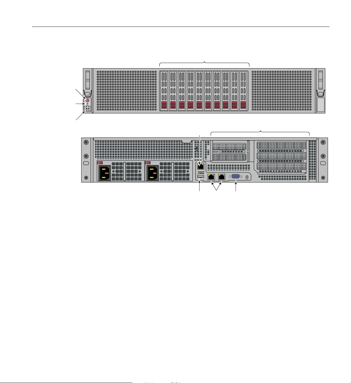
PCI expansion slots
!
2 1
System
reset
System
LEDs
Main
power
Ten disk drive bays
VGA
port
Ethernet
ports
USB
ports
IPMI
LAN
System Features and Major Components
Figure 3-7 2U Service Node Front and Rear Panel Example
Batch Server Node
The batch server function may be combined with login or other service nodes for many
configurations. Additional batch nodes can be added as the total number of user logins increase.
Users login to a batch server in order to run batch scheduler portable-batch system/load-sharing
facility (PBS/LSF) programs. Users login or connect to this node to submit these jobs to the
system compute nodes.
I/O Gateway Node
The I/O gateway server function may be combined with login or other service nodes for many
configurations. If required, the I/O gateway server function can be hosted on an optional 1U or 2U
stand-alone server within the ICE X system.
One or more I/O gateway nodes are supported per system, based on system size and functional
requirement. The node
007-5806-004 43
may be separated from login and/or batch nodes to scale to large
Page 64

3: System Overview
configurations. Users login or connect to submit jobs to the compute nodes. The node also acts as
a gateway from InfiniBand to various types of storage, such as direct-attach, Fibre Channel, or
NFS.
Optional Lustre Nodes Overview
The nodes in the following subsections are used when the SGI ICE X system is set up as a Lustre
file system configuration. In SGI ICE X installations the MDS and OSS functions are generally
on separate nodes within the ICE X system and communicating over a network.
Lustre clients access and use the data stored in the OSS node’s object storage targets (OSTs).
Clients may be compute nodes within the SGI ICE X system or Login, Batch or other service
nodes. Lustre presents all clients with a unified namespace for all of the files and data in the
filesystem, using standard portable operating system interface (POSIX) semantics. This allows
concurrent and coherent read and write access to the files in the OST filesystems. The Lustre MDS
server (see
the format imposed by these file systems. When a client accesses a file, it completes a filename
lookup on the MDS node. As a result, a file is created on behalf of the client or the layout of an
existing file is returned to the client. For read or write operations, the client then interprets the
layout in the logical object volume (LOV) layer, which maps the offset and size to one or more
objects, each residing on a separate OST within the OSS node.
“MDS Node”) and OSS server (see “OSS Node”), will read, write and modify data in
MDS Node
The metadata server (MDS node) uses a single metadata target (MDT) per Lustre filesystem. Two
MDS nodes can be configured as an active-passive failover pair to provide redundancy. The
metadata target stores namespace metadata, such as filenames, directories, access permissions and
file layout. The MDT data is usually stored in a single localized disk filesystem. The storage used
for the MDT (a function of the MDS node) and OST (located on the OSS node) backing
filesystems is partitioned and optionally organized with logical volume management (LVM)
and/or RAID. It is normally formatted as a fourth extended filesystem, (a journaling file system
for Linux). When a client opens a file, the file-open operation transfers a set of object pointers and
their layout from the MDS node to the client. This enables the client to directly interact with the
OSS node where the object is stored. The client can then perform I/O on the file without further
communication with the MDS node.
44 007-5806-004
Page 65

OSS Node
The object storage server (OSS node) is one of the elements of a Lustre File Storage system. The
OSS is managed by the SGI ICE X management network. The OSS stores file data on one or more
object storage targets (OSTs). Depending on the server’s hardware, an OSS node typically serves
between two and eight OSTs, with each OST managing a single local disk filesystem.
An OST is a dedicated filesystem that exports an interface to byte ranges of objects for read/write
operations. The capacity of each OST on the OSS node can range from a maximum of 24 to 128
TB depending on the SGI ICE X operating system and the Lustre release level. The data storage
capacity of a Lustre file system is the available storage total of the capacities provided by the
OSTs.
Reliability, Availability, and Serviceability (RAS)
The SGI ICE X server series components have the following features to increase the reliability,
availability, and serviceability (RAS) of the systems.
• Power and cooling:
– Power supplies within the blade enclosure pair chassis are redundant and can be
hot-swapped under most circumstances.
System Features and Major Components
– A rack-level water chilled cooling option is available for all D-rack configurations.
– Blade enclosures have overcurrent protection at the blade and power supply level.
– Fans (blowers) are redundant in D-rack configurations and can be hot-swapped.
– Fans can run at multiple speeds. Speed increases automatically when temperature
increases or when a single fan fails.
• System monitoring:
– Chassis managers monitor blade enclosure internal voltage, power and temperature.
– Redundant system management networking is available.
– Each blade/node installed has status LEDs that can indicate a malfunctioning or failed
part; LEDs are readable at the front of the system.
– Systems support remote console and maintenance activities.
007-5806-004 45
Page 66

3: System Overview
• Error detection and correction
– External memory transfers are protected by cyclic redundancy check (CRC) error
detection. If a memory packet does not checksum, it is retransmitted.
– Nodes within each blade enclosure exceed SECDED standards by detecting and
correcting 4-bit and 8-bit DRAM failures.
– Detection of all double-component 4-bit DRAM failures occur within a pair of DIMMs.
– 32-bits of error checking code (ECC) are used on each 256 bits of data.
– Automatic retry of uncorrected errors occurs to eliminate potential soft errors.
• Power-on and boot:
– Automatic testing (POST) occurs after you power on the system nodes.
– Processors and memory are automatically de-allocated when a self-test failure occurs.
– Boot times are minimized.
46 007-5806-004
Page 67

System Components
The SGI ICE X series system features the following major components:
• 42U D-rack. This is a custom rack used for both the compute and I/O rack in the SGI ICE X
• 42U M-rack. These multi-cell (M-Cell) rack assemblies use a dedicated cooling rack for
• Blade enclosure pair. This sheetmetal enclosure contains the two enclosures holding up to
• Fan (blower) enclosure (D-rack systems). This sheetmetal enclosure is installed
System Components
series. Up to two blade enclosure pairs can be installed in each rack. Note that multi-rack
systems will often have a dedicated I/O rack holding GigE switches, RLCs, Admin servers
and additional service nodes. Water-cooled D-racks are optionally available.
each two compute racks used. Water cooling of the individual nodes is accomplished by a
separate dedicated cooling-distribution rack (CDU). See
Assemblies” in Chapter 4 for additional information.
36 compute blades, up to four chassis manager boards, up to four InfiniBand fabric I/O
blades and front-access power supplies for the SGI ICE X series computers. The enclosure
pair is 21U high.
blade enclosure pair system front components. The blade enclosure pair used in M-Cell
configurations employs side-mounted power supplies, see
back-to-back with each blade enclosure pair in a D-rack system. The fan enclosure consists
of two 6-blower enclosures and two dedicated power supplies.
an example of the fan enclosure.
Figure 3-8 on page 48 shows the D-Rack version of the SGI ICE X series
“SGI ICE X M-Cell Rack
Figure 3-10 on page 50.
Figure 7-3 on page 99 shows
• Single-wide compute blade. Holds one or two node boards and up to 16 memory DIMMs.
See
Figure 3-9 on page 49 for an example of blade number assignments.
• 1U RLC (rack leader controller). One 1U rack leader server is required for each eight
CMCs in a system. High-availability configurations using redundant RLCs are supported.
• 1U Administrative server. This server node supports an optional console and
administrative software.
• 1U Service node. Additional 1U server(s) can be added to a system rack and used
specifically as an optional login, batch, MDS, OSS or other service node. Note that these
service functions cannot be incorporated as part of the system RLC or administration server.
• 2U Service node. An optional 2U service node may be used as a login, batch, MDS, OSS or
fabric node. In smaller systems, multiple functions may be combined on one server.
PCIe options available may vary, check with your SGI sales or support representative.
007-5806-004 47
Page 68
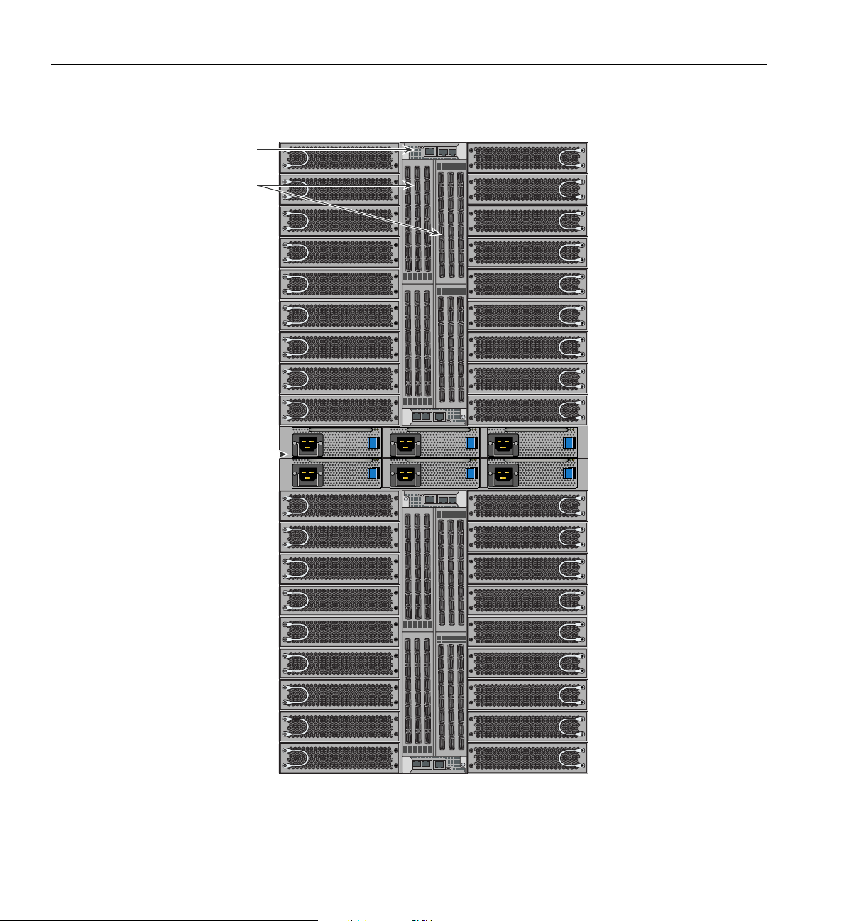
CMC-0 CMC-1 ACC
CNSL RES HB PG
CMC-0 CMC-1 ACC
CNSL RES HB PG
Chassis manager
CMC-0 CMC-1 ACC
CNSL RES HB PG
CMC-0 CMC-1 ACC
CNSL RES HB PG
Switch blades
Power supplies
3: System Overview
Figure 3-8 SGI ICE X Series D-Rack Blade Enclosure Pair Components Example
48 007-5806-004
Page 69
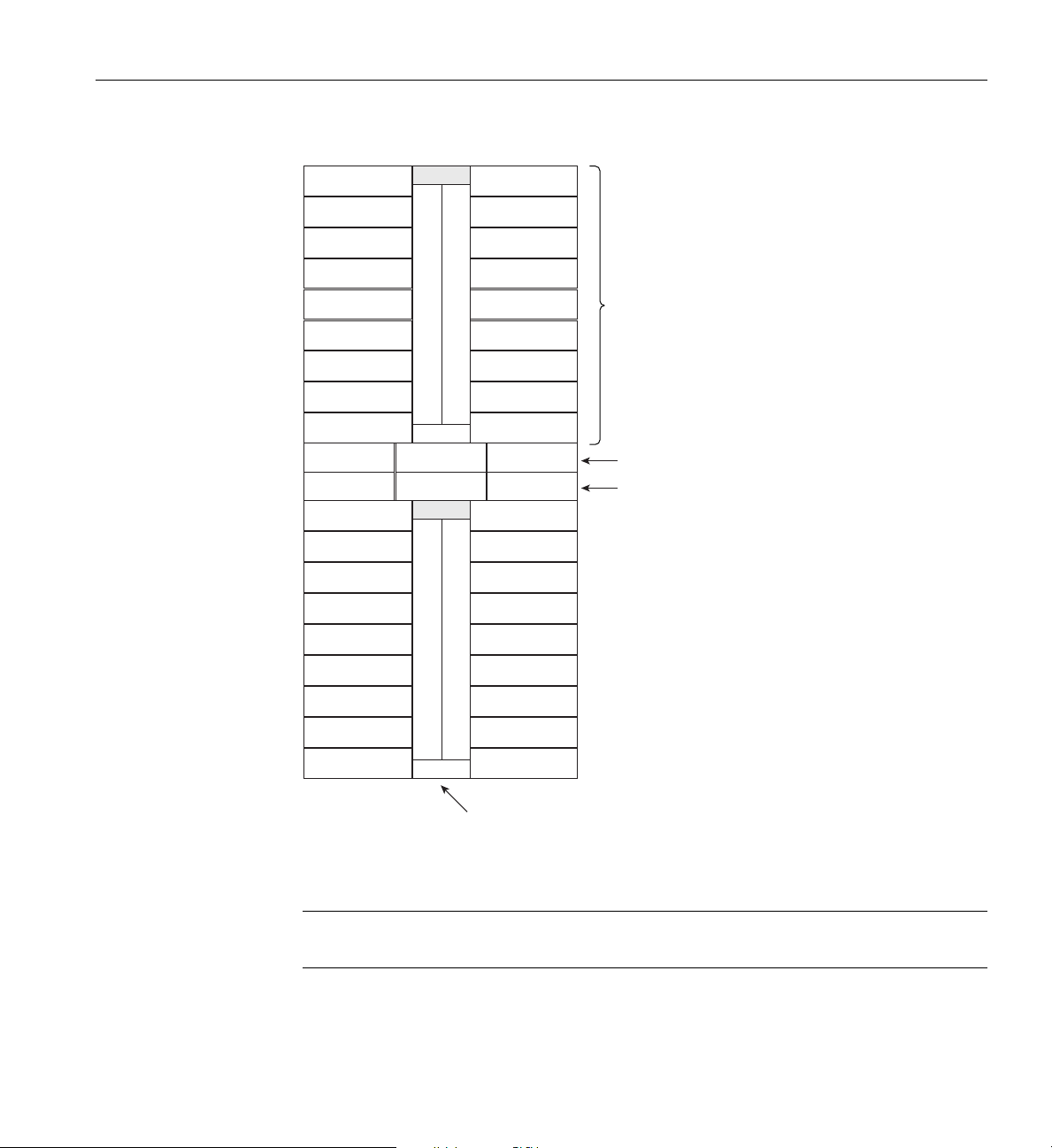
Blade slot 8
Blade slot 7
Blade slot 6
Blade slot 5
Blade slot 4
Blade slot 3
Blade slot 2
Blade slot 1
Blade slot 0
Blade slot 17
Blade slot 16
Blade slot 15
Blade slot 14
Blade slot 13
Blade slot 12
Blade slot 11
Blade slot 10
Blade slot 9
InfiniBand switch blade slot 1
InfiniBand switch blade slot 0
CMC 1
CMC 0
PS 0
PS 1 PS 2
PS 0 PS 1 PS 2
Blade slot 8
Blade slot 7
Blade slot 6
Blade slot 5
Blade slot 4
Blade slot 3
Blade slot 2
Blade slot 1
Blade slot 0
Blade slot 17
Blade slot 16
Blade slot 15
Blade slot 14
Blade slot 13
Blade slot 12
Blade slot 11
Blade slot 10
Blade slot 9
InfiniBand switch blade slot 1
InfiniBand switch blade slot 0
CMC 1
CMC 0
Chassis management
controller
9 Compute
blade slots
Power shelf 0
Power shelf 1
System Components
Figure 3-9 Single-node D-Rack Blade Enclosure Pair Component Front Diagram
Note: IRU enclosures using single-node blades use one CMC, enclosures using dual-node blades
must use two CMC boards.
007-5806-004 49
Page 70
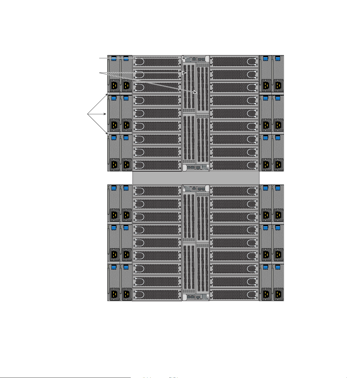
CMC-0 CMC-1 ACC CNSLRES HBPG
CMC-0 CMC-1 ACC CNSLRES HBPG
CMC-0 CMC-1 ACC CNSLRES HBPG
CMC-0 CMC-1 ACC CNSLRES HBPG
Power supplies
Rack mount shelf
Chassis manager
Switch blades
Figure 3-10 M-Rack Blade Enclosure Pair Components Example
Page 71

D-Rack Unit Numbering
Blade enclosures in the D-racks are not identified using standard units. A standard unit (SU) or
unit (U) is equal to 1.75 inches (4.445 cm). Enclosures within a rack are identified by the use of
module IDs 0, 1, 2, and 3, with enclosure 0 residing at the bottom of each rack. These module IDs
are incorporated into the host names of the CMC (i0c, i1c, etc.) and the compute blades (r1i0n0,
r1i1n0, etc.) in the rack.
Rack Numbering
Each rack in a multi-rack system is numbered with a single-digit number sequentially beginning
with (001). A rack contains blade enclosures, administrative and rack leader server nodes, service
specific nodes, optional mass storage enclosures and potentially other options.
Note: In a single compute rack system (D-rack), the rack number is always (001).
The number of the first blade enclosure will always be zero (0). These numbers are used to identify
components starting with the rack, including the individual blade enclosures and their internal
compute-node blades. Note that these single-digit ID numbers are incorporated into the host
names of the rack leader controller (RLC) as well as the compute blades that reside in that rack.
Optional SGI Remote Services (SGI RS)
Optional System Components
Availability of optional components for the SGI ICE X series of systems may vary based on new
product introductions or end-of-life components. Some options are listed in this manual, others
may be introduced after this document goes to production status. Check with your SGI sales or
support representative for the most current information on available product options not discussed
in this manual.
Optional SGI Remote Services (SGI RS)
The optional SGI RS system automatically detects system conditions that indicate potential future
problems and then notifies the appropriate personnel. This enables you and SGI global support
teams to pro-actively support systems and resolve issues before they develop into actual failures.
007-5806-004 51
Page 72

SGI Remote Services provides a secure connection to SGI Customer Support - on demand. This
can ensure business continuance with SGI systems management and optimization.
SGI Remote Services Primary Capabilities
• 24x7 remote monitoring and data gathering of SGI customer systems
• Alerts and notification on changes, failures and potential failures
• Log files immediately available
• Configuration fingerprint
• Secure file transfer
• Optional secure remote access to customer systems
SGI Remote Services Benefits
• Improved uptime and system availability
• Proactive identification of issues before they create an outage
• Increase system stability by monitoring hardware and software version compatibility
• Reduced time to resolve support cases
• Greater operational efficiency
• Less involvement of customer staff during troubleshooting
• Faster support case resolution
• Improved productivity
Proactive potential problem identification can result in higher system availability.
Automated Alerts and, in some instances, Case Opening results in faster problem resolution time
and less direct involvement required by Customer Support Teams. SGI Remote Services is
available for all currently shipping SGI ICE, UV and Rackable systems and also other specific
SGI systems. Check with your SGI sales or service representative for more details.
Page 73
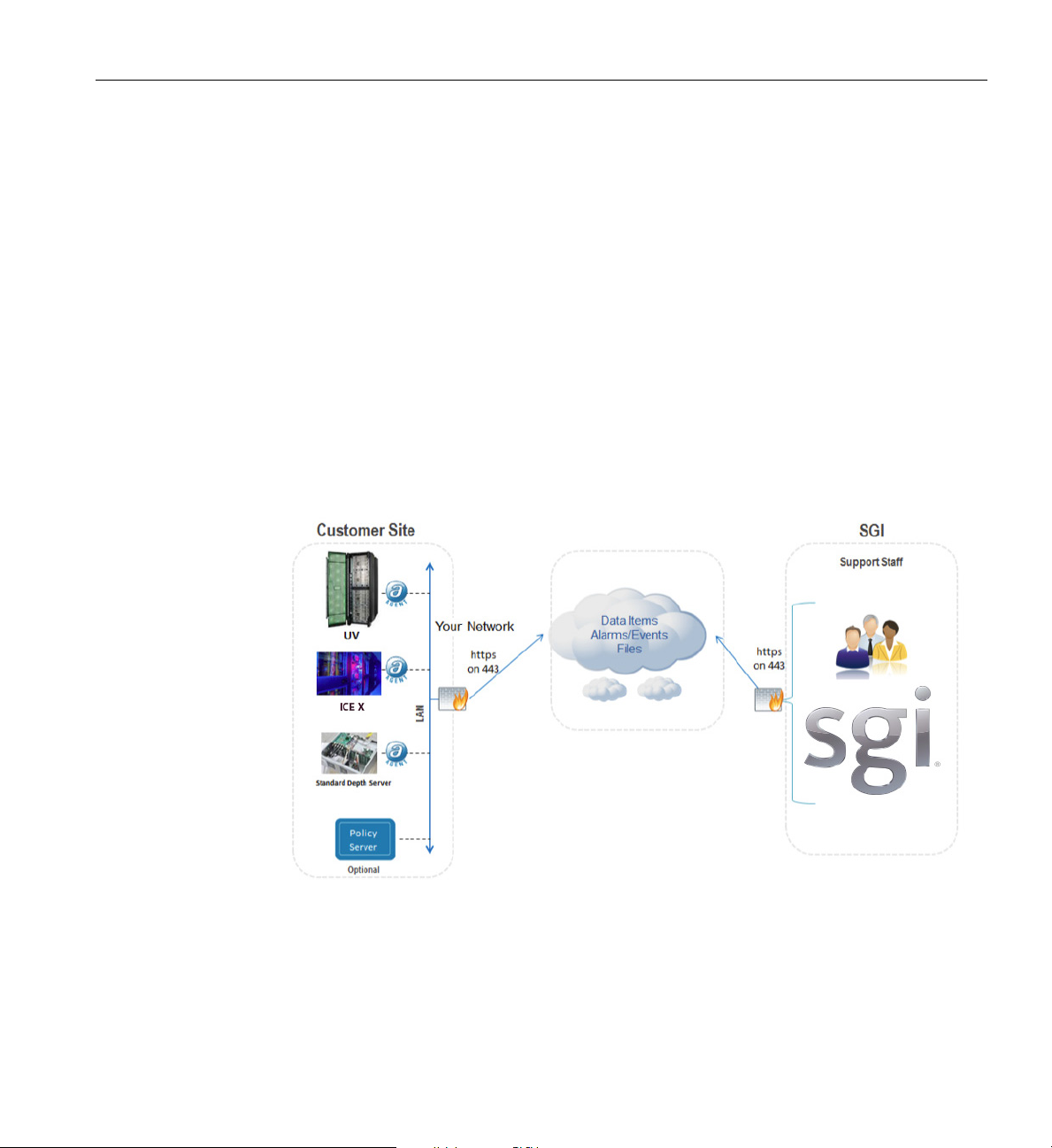
SGI Remote Service Operations Overview
An SGI Support Services Software Agent runs on each SGI system at your location, enabling
remote system monitoring and secure communication to SGI Support staff. Your basic hardware
and software configuration as well as system health information is captured and stored in the
Cloud. Figure 3-11 shows an example visual overview of the monitoring and response process.
Cloud intelligence automatically reviews select Event Logs around the clock (every five minutes)
entify potential failure information. If the Cloud intelligence detects a critical Event, it
to id
notifies SGI support personnel.
Optional SGI Remote Services (SGI RS)
This monitoring requires no changes to customer systems
or firewalls as long as the SGI Agent
can send HTTPS messages to highly secure Cloud and Global Access Servers. It will also have no
impact on customer network or system performance. All communication between SGI global
support and customer systems is kept secure using Secure Socket Layer (SSL) encryption. All
communication with SGI is initiated from the customer site using HTTPS protocol on port 443.
Figure 3-11 SGI Remote Services Process Overview
007-5806-004 53
Page 74

3: System Overview
SGI Warranty Levels
SGI Electronic Support services are available to customers who have a valid SGI Warranty or
optional support contract. Additional electronic services may become available after publication
of this document. To purchase a support contract that allows you to use all available SGI
Electronic Support services, contact your SGI sales representative. For more information about
the various support contracts, see the following Web pages:
http://www.sgi.com/support
http://www.sgi.com/services/support
54 007-5806-004
Page 75

Overview
Chapter 4
4. Rack Information
This chapter describes the physical characteristics of the tall (42U) ICE X racks in the following
sections:
• “Overview” on page 55
• “SGI ICE X Series D-Rack (42U)” on page 56
• “ICE X D-Rack Technical Specifications” on page 61
• “SGI ICE X M-Cell Rack Assemblies” on page 62
• “M-Cell Functional Overview” on page 63
At the time this document was published only specific SGI ICE X racks were approved for ICE X
systems shipped from the SGI factory. See
examples. Contact your SGI sales or support representative for more information on configuring
SGI ICE X systems in non-ICE X factory rack enclosures.
007-5806-004 55
Figure 4-1 on page 57 and Figure 4-5 on page 62 for
Page 76

4: Rack Information
SGI ICE X Series D-Rack (42U)
The SGI tall D-Rack (shown in Figure 4-1 on page 57) has the following features and
components:
• Front and rear door. The front door is opened by grasping the outer end of the
rectangular-shaped door piece and pulling outward. It uses a key lock for security purposes
that should open all the front doors in a multi-rack system (see
front door is required on every rack.
Note: The front door and rear door locks are keyed differently. The optional water-chilled
rear doors (see Figure 4-3 on page 59) do not use a lock.
Up to four optional 10.5 U-high (18.25-inch) water-cooled doors can be installed on the rear
of the SGI ICE X D-Rack.
Each air-cooled rack has a key lock to prevent unauthorized access to the system via the rear
door, see
have a master key that locks and unlocks all rear doors in a system. You cannot use the rear
door key to secure the front door lock.
Figure 4-4 on page 60. In a system made up of multiple air-cooled racks, rear doors
Figure 4-2 on page 58). A
• Cable entry/exit area. Cable access openings are located in the front floor and top of the
rack. Cables are only attached to the front of the IRUs; therefore, most cable management
occurs in the front and top of the rack. Stand-alone administrative, leader and login server
modules are the exception to this rule and have cables that attach at the rear of the rack. Rear
cable connections will also be required for optional storage modules installed in the same
rack with the enclosure(s). Optional inter-rack communication cables pass through the top of
the rack. I/O and power cables normally pass through the bottom of the rack.
• Rack structural features. The rack is mounted on four casters; the two rear casters swivel.
There are four leveling pads available at the base of the rack. The base of the rack also has
attachment points to support an optional ground strap, and/or seismic tie-downs.
• Power distribution units in the rack. Up to sixteen may be required for a single enclosure
pair system as follows:
– up to 8 outlets for an enclosure pair (including GigE switch configuration)
– two outlets for the rear fan (blower) enclosure power supplies
– 4 outlets for administration and RLC servers (in primary rack)
– 2 outlets for a service node (server)
– Allow eight or more outlets for an additional enclosure pair in the system
56 007-5806-004
Page 77
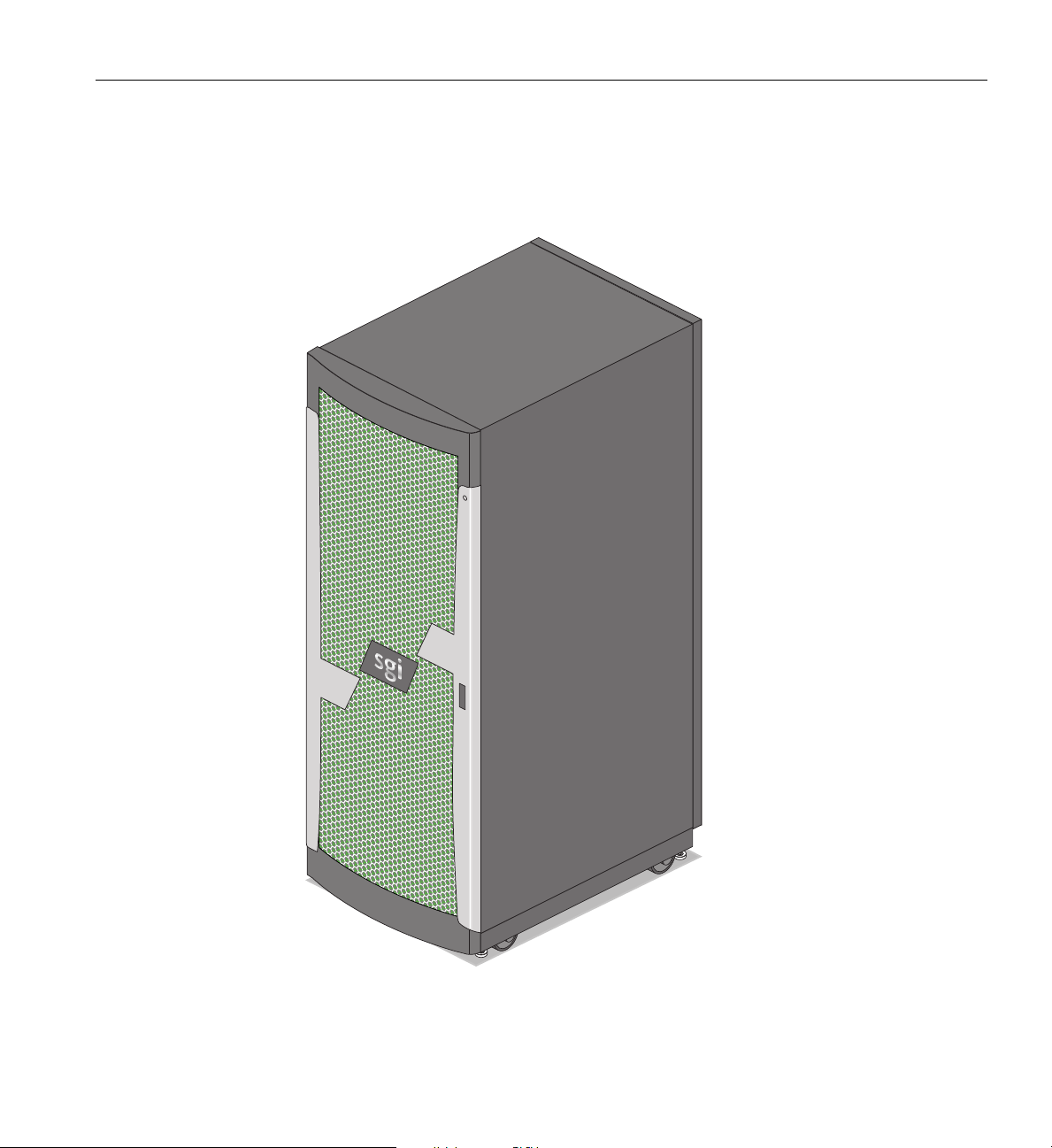
SGI ICE X Series D-Rack (42U)
Note that up to 16 power outlets may be needed to power a single blade enclosure pair and
supporting servers installed in a single rack. Optional single-phase PDUs can be used in SGI
ICE X racks dedicated to I/O functionality.
Figure 4-1 SGI ICE X Series D-Rack Example
007-5806-004 57
Page 78
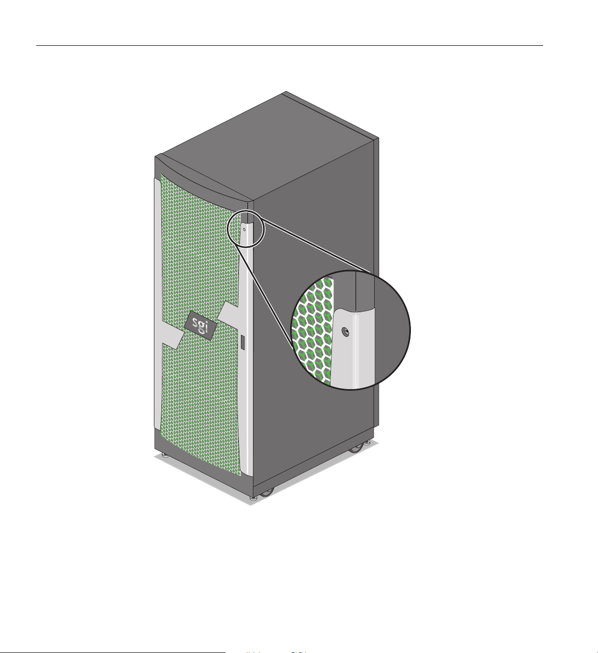
4: Rack Information
Figure 4-2 Front Lock on Tall (42U) D-Rack
58 007-5806-004
Page 79
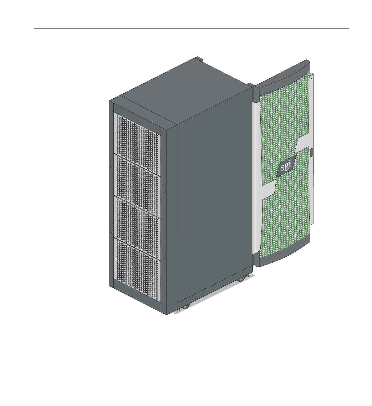
SGI ICE X Series D-Rack (42U)
Figure 4-3 Optional Water-Chilled Door Panels on Rear of ICE X D-Rack
007-5806-004 59
Page 80
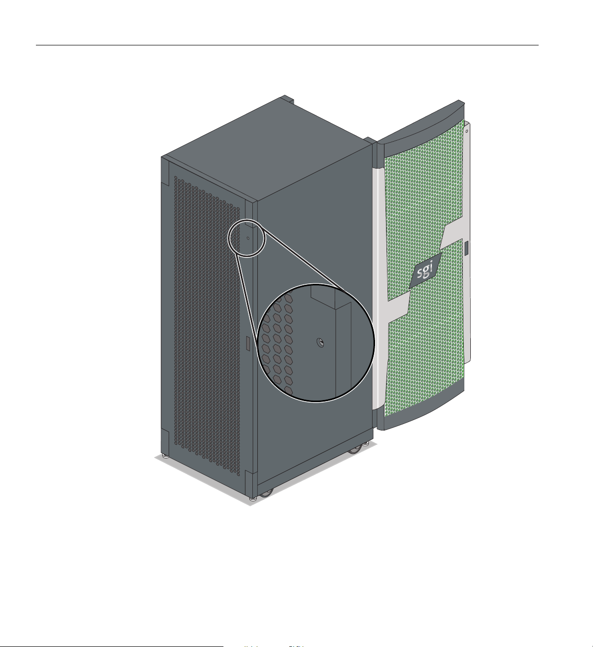
4: Rack Information
Figure 4-4 Air-Cooled D-Rack Rear Door and Lock Example
60 007-5806-004
Page 81

ICE X D-Rack Technical Specifications
Table 4-1 lists the technical specifications of the SGI ICE X series D-Rack.
Table 4-1 Tall SGI ICE X D-Rack Technical Specifications
Characteristic Specification
Height 79.5 in. (201.9 cm) 82.25 in (208.9 cm) with 2U top
Width 24 in. (61 cm) - optionally expandable
Depth 49.5 in. (125.7 cm) - air cooled; 50.75 in. (128.9 cm)
- water
cooled
Weight (full) ~2,500 lbs. (1,136 kg) approximate (water cooled)
Shipping weight (max) ~2,970 lbs. (1,350 kg) approximate maximum
ICE X D-Rack Technical Specifications
Voltage range
Nominal
Tolerance range
Frequency
Nominal
Tolerance range
Phase required 3-phase (optional single-phase ava
Power requirements (max) 34.58 kVA (33.89 kW)
Hold time 16 ms
Power cable 12 ft. (3.66 m) pluggable cords
North America/International
200-240 VAC /230 VAC
180-264 VAC
North America/International
60 Hz /50 Hz
47-63 Hz
ilable in I/O rack)
Important: The D-rack’s optional water-cooled door panels only provide cooling for the bottom
42U of the rack. If the top of the rack is “expanded” 2U, 4U, or 6U, to accommodate optional
system components, the space in the extended zone is not water cooled.
See “System-level Specifications” in Appendix A for a more complete listing of SGI ICE X
system operating specifications and env
ironmental requirements.
007-5806-004 61
Page 82
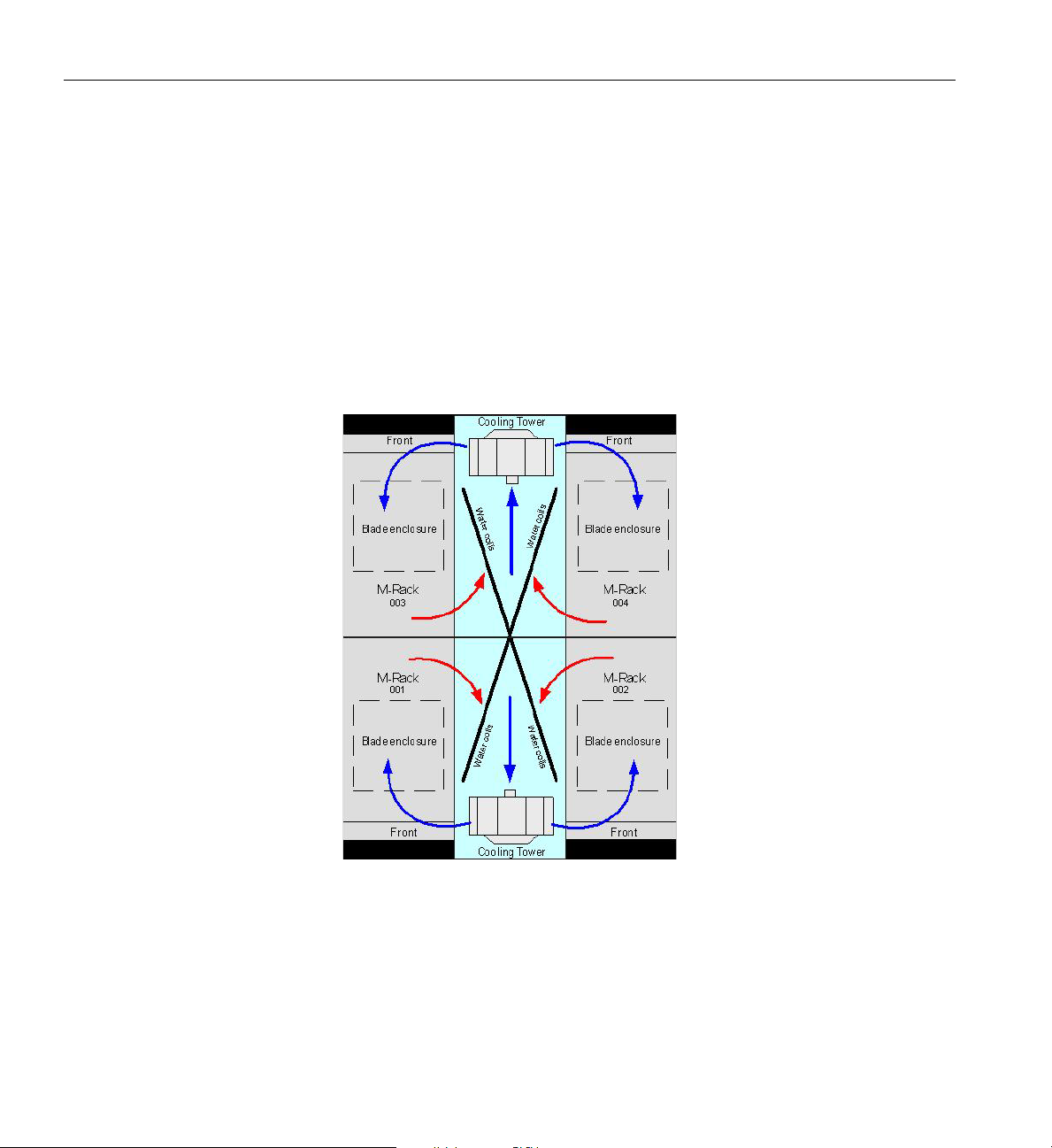
4: Rack Information
SGI ICE X M-Cell Rack Assemblies
Specific SGI ICE X system configurations require the use of enhanced “closed-loop” cooling and
the compute rack assemblies are generally referred to as an “M-Cell”. A complete M-Cell
assembly consists of four compute racks and two cooling racks, see Figure 4-5 for an example.
The racks are connected together to create a sealed
innovative difference in an M-Cell rack system is that it does not exhaust heated air into the
surrounding environment; this means an M-Cell does not add to the heat load of the computer
room. Multiple M-Cells can be interconnected and configured to create very large systems. Most
M-Cell configurations also require the use of a separate cooling distribution rack unit (CDU rack)
not shown in Figure 4-5.
unit to support closed-loop cooling. One
Figure 4-5 M-Cell Rack Configuration Example (Top View)
The smallest M-Cell assembly consists of two compute racks with a cooling rack in between. This
smaller unit is often referred to as a “½-Cell” rack assembly or simply a “half-cell”. See Figure 4-7
on page 65 for an example.
62 007-5806-004
Page 83

M-Cell Functional Overview
An M-Cell consists of M-racks and cooling racks and in most configurations a special cooling
distribution rack (CDU). When liquid-cooled blades are used in the system, the separate CDU
supplies water that dissipates heat off the system CPUs.
There is one 24-inch wide x 93-inch high cooling rack for every two M-racks in an M-Cell. The
ing rack circulates conditioned air through the M-racks to cool the components within the
cool
M-rack assembly. Figure 4-6 on page 64 shows the cooling rack at the center
SGI logo on the front. Note that the cooling rack does no
components and is used strictly for cooling the M-Cell assembly.
SGI ICE X M-Cell Rack Assemblies
of the array with the
t accommodate any compute or storage
The compute racks used in an M-Cell co
nfiguration are 33-inches (83.8 cm) wide; other size and
weight differences (compared to the D-Rack) are noted in Tab le 4-2. In the M-rack there are six
power shelves per blade enclosure pair.
Table 4-2 SGI ICE X M-Rack Technical Specifications
Characteristic Specification
Height 93 in. (236.2 cm)
Width 33 in. (83.8 cm)
Depth 48.4 in. (121.9 cm)
Weight (full) ~2,426 lbs. (1,103 kg) approximate
Shipping weight (max) ~2,850 lbs. (1,295 kg) approximate
Voltage range
Nominal
Tolerance range
Frequency
Nominal
Tolerance range
Phase required single-phase or optional 3-phase
North America/International
200-240 VAC /230 VAC
180-264 VAC /180-254 VAC
North America/International
60 Hz / 50 Hz
47-63 Hz / 47-63
Power requirements (max) 76 kVA (77.47 kW)
Hold time 20 ms
Power cable 10 ft. (3.0 m) pluggable cords
007-5806-004 63
Page 84
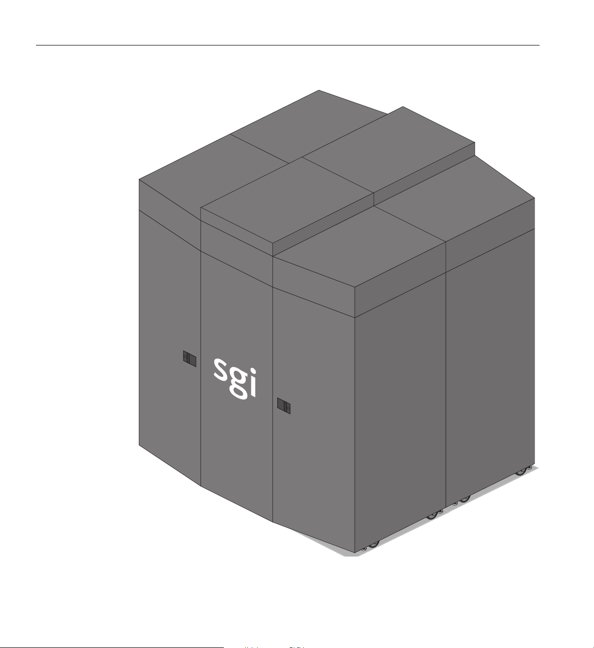
4: Rack Information
Figure 4-6 SGI ICE X Multi-Cell (M-Cell) Rack Array Example
64 007-5806-004
Page 85
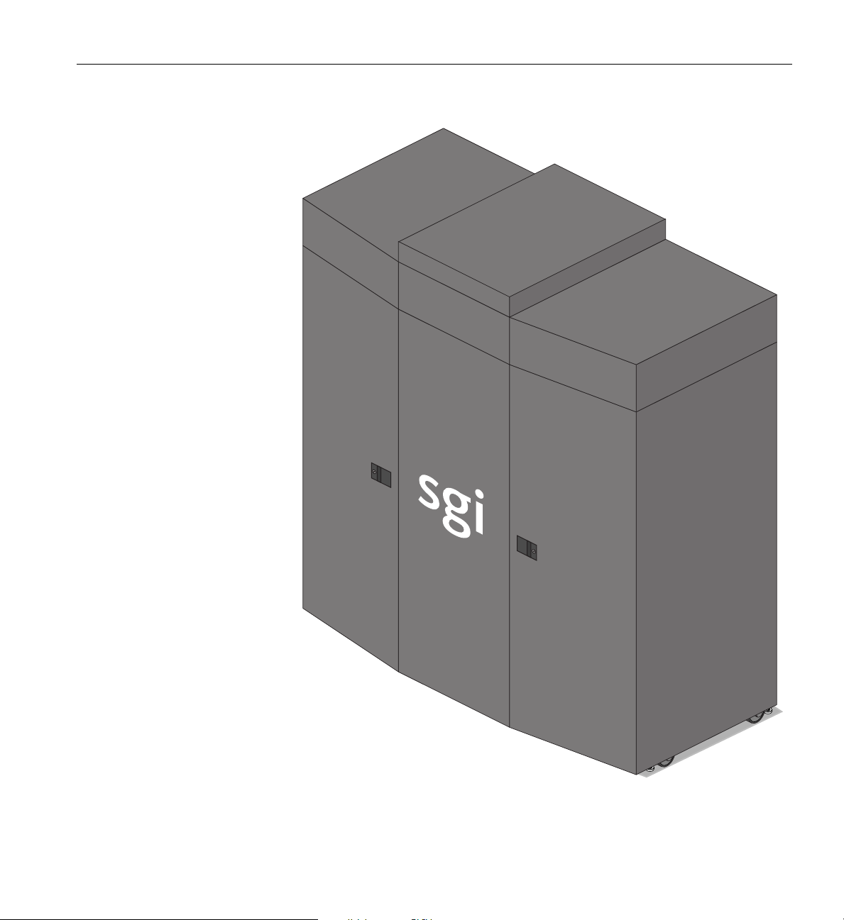
SGI ICE X M-Cell Rack Assemblies
Figure 4-7 Half M-Cell Rack Assembly (½-Cell) Example
007-5806-004 65
Page 86

Page 87

Chapter 5
5. SGI ICE X Administration/Leader Servers
This chapter describes the function and physical components of the administrative/rack leader
control servers (also referred to as nodes) in the following sections:
• “Overview” on page 68
• “System Hierarchy” on page 68
• “1U Rack Leader Controller and Administration Server” on page 71
For purposes of this chapter “administration/controller server” is used as a catch-all phrase to
describe the stand-alone servers that act as management infrastructure controllers. The specialized
functions these servers perform within the SGI ICE X system primarily include:
• Administration and management
• Rack leader controller (RLC) functions
Other servers described in this chapter can be configured to provide additional services, such as:
• Fabric management (usually used with larger systems)
• Login
• Batch
• I/O gateway (storage)
• MDS node (Lustre configurations)
• OSS node (Lustre configurations)
Note that these functions are performed by the system’s “service nodes” which are additional
individual servers set up for single or multiple service tasks.
007-5806-004 67
Page 88

5: SGI ICE X Administration/Leader Servers
Overview
User interfaces consist of the Compute Cluster Administrator, the Compute Cluster Job Manager,
and a Command Line Interface (CLI). Management services include job scheduling, job and
resource management, Remote Installation Services (RIS), and a remote command environment.
The administrative controller server is connected to the system via a Gigabit Ethernet link, (it is
not directly linked to the system’s InfiniBand communication fabric).
Note that the system management software runs on the administrative node, RLC and service
nodes as a distributed software function. The system management software performs all of its
tasks on the ICE X system through an Ethernet network.
The administrative controller server (also known as the system admin controller) is at the top of
the distributed management infrastructure within the SGI ICE X system. The overall SGI ICE X
series management is hierarchical (see the following subsection
Figure 5-1 on page 70), with the RLC(s) communicating with the compute nodes via CMC
interconnect.
System Hierarchy
“System Hierarchy” and also
The SGI ICE X system has a four-tier, hierarchical management framework. The ICE X systems
contain hardware and software components as follows:
• System Admin Controller (SAC) - one per system
• Rack Leader Controller (RLC) - one per 8 CMCs
• Chassis Management Controller (CMC) - one or two per blade enclosure
• 48-port Gigabit Ethernet switch (note that some system racks may contain more than one
48-port switch - reference
• Baseboard Management Controller (BMC) - one per each of the following:
– Compute node (note that some blades may contain more than one logical node)
–SAC
–RLC
– Service node
68 007-5806-004
Figure 2-2 on page 20 as an example)
Page 89

Communication Hierarchy
Overview
Communication within the overall management framework is as follows:
Admin Node
The Admin node communicates with the following:
• All rack leader controllers (RLCs)
• All cooling rack controllers (CRCs)
• All cooling distribution units (CDUs)
Rack Leader Controller (RLC)
The RLCs within a “logical rack” (see tip that follows) communicate with the following:
• All chassis management controllers (CMCs) within the same logical rack as the RLC.
Chassis Management Controllers
The CMCs within a logical rack communicate with the following:
• The rack leader controllers (RLCs) within the same logical rack
The following two components communicate with CMCs only in M-Cell rack systems:
• The cooling rack controller (CRC) assigned to the same logical rack as the CMC
• The cooling distribution unit (CDU) assigned to the same logical rack as the CMC
Tip: A logical rack can be one or two physical racks. The number of CMCs in a blade
enclosure pair determines the number of physical racks in a logical rack. If there are two
CMCs in a blade enclosure pair, then one logical rack equals two physical racks. If there are
four CMCs in a blade enclosure pair, then one logical rack equals one physical rack.
The logical rack is based on the RLC. There is one RLC in each logical rack. An RLC supports a
maximum of eight CMCs. Therefore, if there are eight CMCs in one rack then one logical rack
equals one physical rack.
007-5806-004 69
Page 90

System management hierarchy
Each RLC talks to a maximum of 8 CMCs
A maximum of 144 compute blades per rack leader controller
Compute blade
Compute blade
Compute blade
Compute blade
Compute blade
Compute blade
Compute blade
Compute blade
Compute blade
Compute blade
Rack leader
controller (RLC)
Rack Cooling
Tower (CRC)
M-Cell systems only
Chassis Management
Controllers (CMC)
Rack leader
controller (RLC)
Rack Cooling
Distribution Unit (CDU)
M-Cell systems only
Customer LAN
48-port GigE Switch
(System Control GigE Backbone)
VLAN1 and VLAN4
Board Management
Controllers (BMC)
Each CMC talks to a
maximum of 18 BMCs
One BMC per
compute node
VLAN3
VLAN3
VLAN3 and
VLAN4
Service
Nodes
VLAN1
VLAN1 and
VLAN4
System Admin
Node
VLAN1 and VLAN3
5: SGI ICE X Administration/Leader Servers
70 007-5806-004
Figure 5-1 SGI ICE X System Administration Hierarchy Example Diagram
Page 91
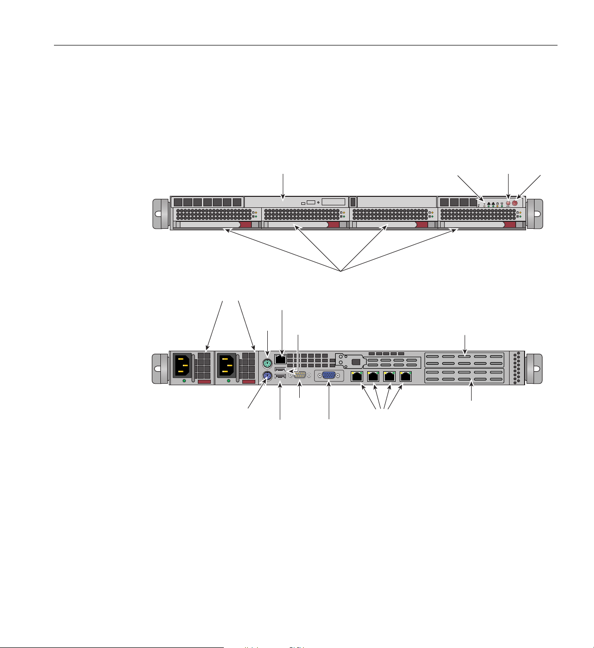
1U Rack Leader Controller and Administration Server
Slim DVD drive option
System
reset
System
LEDs
Main
power
Disk drive bays
Mouse
BMC Port
USB
Port 1
Power Supply Module
USB
Port 0
Keyboard
VGA Port
COM
Port1
LAN ports 1-4
Full-height (full-depth)
x16 PCIe slot
Full-height (half-depth)
x16 PCIe slot
1U Rack Leader Controller and Administration Server
Figure 5-2 shows the front and rear views of the 1U server used as a Rack Leader Controller
(RLC) and also used separately as an adm
inistration server for the ICE X system.
Figure 5-2 1U Rack Leader Controller (RLC) Server Front and Rear Panels
The system administrative controller unit acts as the SGI ICE X system’s primary interface to the
“outside world”, typically a local area network (LAN). The server is used by administrators to
provision and manage cluster functions using SGI’s cluster management software. Refer to the
SGI Management Center Administration Guide for Clusters, (P/N 007-6358-00x) if you need
more detailed information.
Batch or login functions most often run on individual
separate “service” nodes, especially when
the system is a large-scale multi-rack installation or has a large number of users. The 1U server
007-5806-004 71
Page 92

5: SGI ICE X Administration/Leader Servers
may also be used as a separate (non-RLC/admin) login, batch, I/O, MDS, OSS or fabric
management node. See the section
administration and support server types and additional functional descriptions.
1U Service Nodes
The 1U rack leader controller server (shown in Figure 5-2 on page 71) can be optionally used as
a non-RLC/admin service node. The following subsection (“C1104G-RP5 1U Service Node”)
describes an additional 1U service node that is never used as the system administrator or RLC
node in an ICE X system.
C1104G-RP5 1U Service Node
The Rackable C1104G-RP5 server is a 1U rackmount service node used as a login, batch, fabric
management, I/O, MDS, or OSS system. At the heart of the system is a dual-processor serverboard
based on the Intel C602 chipset. The serverboard (motherboard) supports two multi-core, Intel
Xeon E5-2600 series processors. Separate QPI link pairs connect the two processors and the I/O
hub in a network on the board.
“Modularity and Scalability” on page 38 for a list of
The serverboard has eight DIMM slots (four per processor) that support DDR3
1600/1333/1066/800 MHz RDIMMs.
The system supports four hard disk drives and up to three internal optional GPUs. An external
low-profile PCIe 3.0 x8 option card slot is also supported. Available GPU and PCIe option cards
may be limited, check with your SGI sales or service representative for additional information.
Figure 5-3 on page 73 shows the front and rear panel features of the C1104G-RP5 service node.
See the SGI Rackable C1104G-RP5 System User Guide (P/N 007-5839-00x) for more detailed
information on this 1U service node.
72 007-5806-004
Page 93
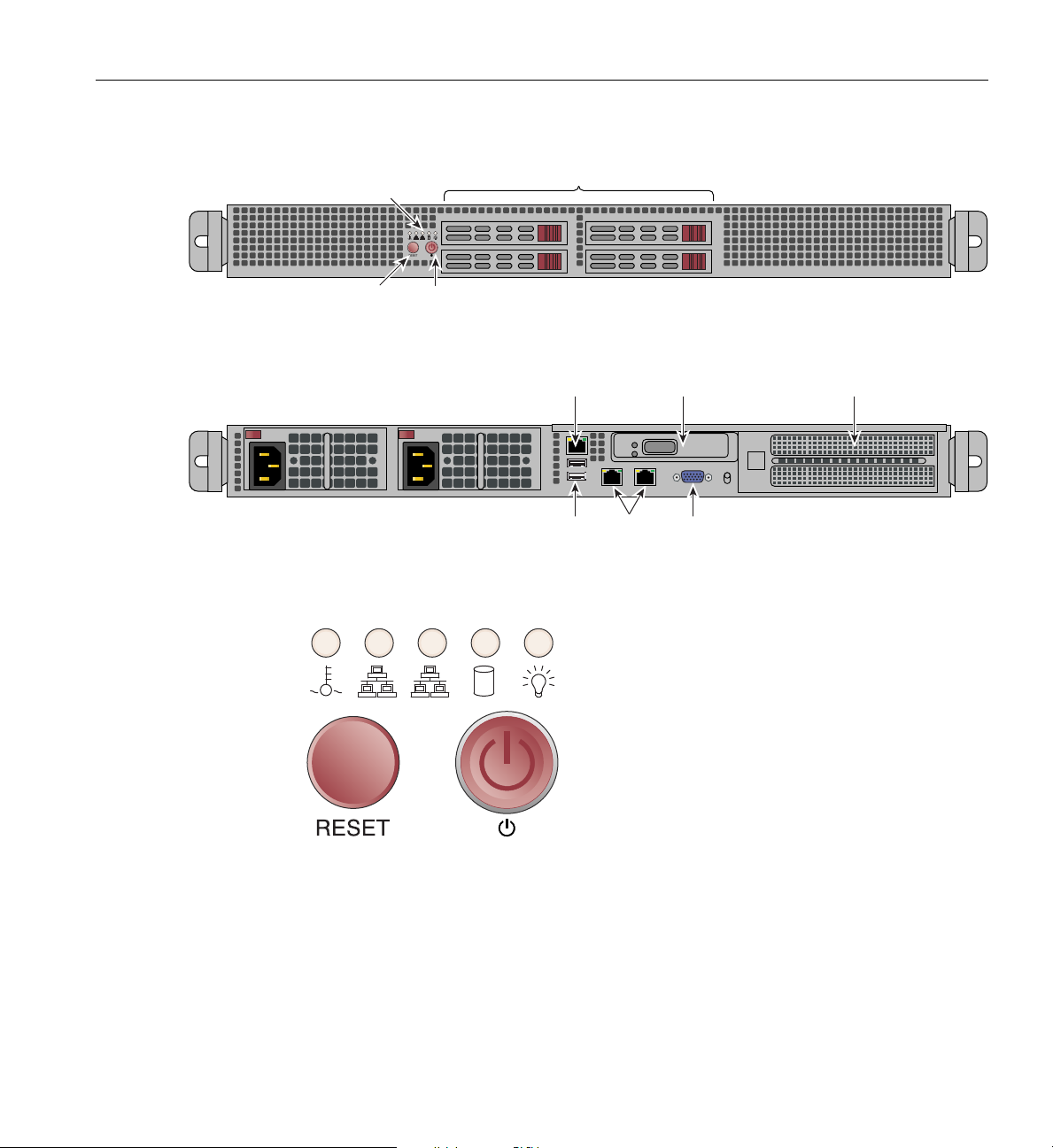
System
reset
Four disk drive bays
21
System
LEDs
Main
power
VGA
port
Ethernet
ports
USB
ports
IPMI
LAN
PCIe low-profile
expansion slot
Optional GPU or
x16 full-height PCIe slot
Figure 5-3 SGI Rackable C1104G-RP5 1U Service Node Front and Rear Panels
21
1U Service Nodes
Figure 5-4 SGI Rackable C1104G-RP5 System Control Panel and LEDs
From left to right the LED indicators are:
• Overheat/fan fail/UID
• LAN1 and LAN2 network indicators
• Hard drive activity and power good LEDs
007-5806-004 73
Page 94
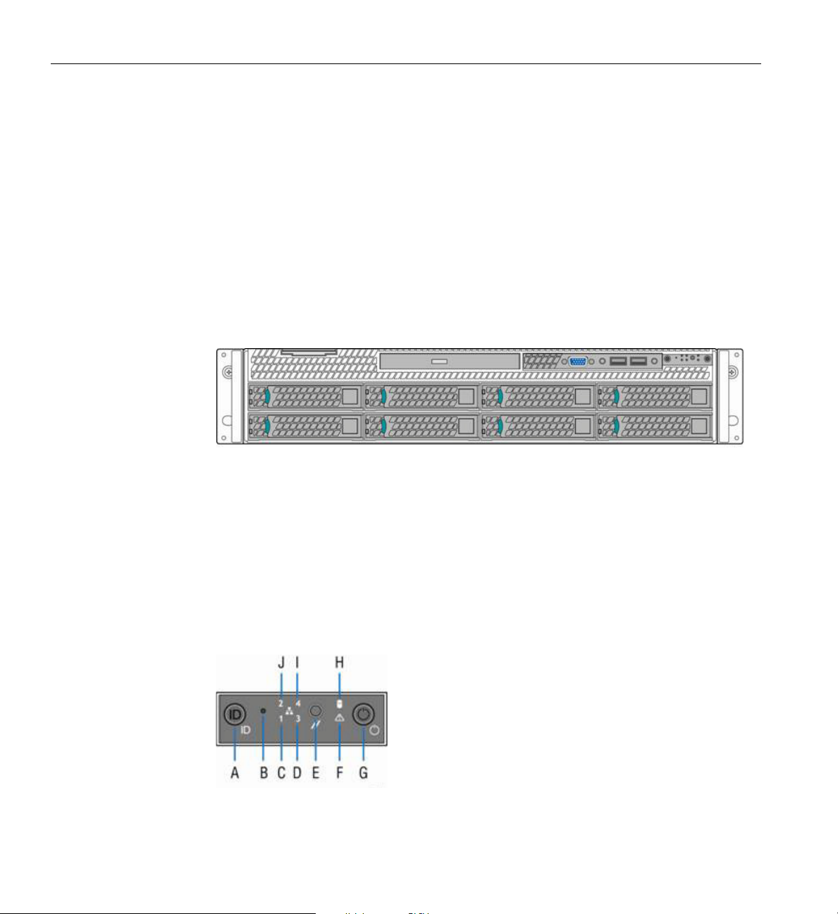
5: SGI ICE X Administration/Leader Servers
2U Service Nodes
For systems using a separate login, batch, I/O, fabric management, or Luster service node; the
following SGI 2U servers are also available as options.
RP2 2U Service Nodes
The SGI Rackable RP2 standard-depth servers are 2U rackmount sevice nodes. Each model of the
server has two main subsystems: the 2U server chassis and a dual-processor serverboard. The RP2
system offered is called SGI Rackable C2108-RP2 (and uses up to 8 hard disk drives). Figure 5-5
shows a front view example of the C2108-RP2 service node.
Figure 5-5 8-HDD Configuration RP2 Service Node Front Panel Example
See the SGI Rackable RP2 Standard-Depth Servers User Guide (P/N 007-5837-00x) for more
detailed information on the RP2 service nodes.
RP2 Service Node Front Controls
The control panel on the C2108-RP2 service node has a horizontal orientation. Figure 5-6 shows
an example of the control panel layout on the server. Table 5-1 on page 75 identifies the functions
of the individual buttons and LED indicators shown.
Figure 5-6 C2108-RP2 Service Node Front Control Panel—Horizontal Layout
74 007-5806-004
Page 95
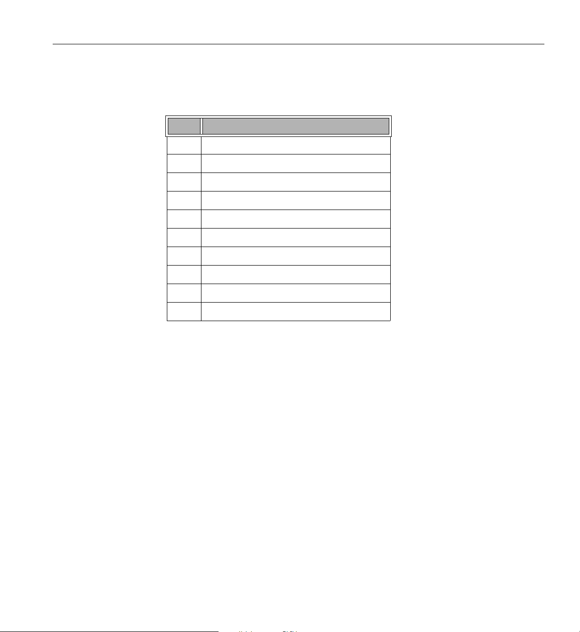
Table 5-1 C2108-RP2 Control Panel Components
Label Description
2U Service Nodes
A System ID button with inte
B NMI button (recessed, tool required for use)
C NIC-1 Activity LED
D NIC-3 Activity LED
E System Cold Reset button
F System Status LED
G Power button with i
H Hard Drive Activity LED
I NIC-4 Activity LED
J NIC-2 Activity LED
grated LED
ntegrated LED
007-5806-004 75
Page 96
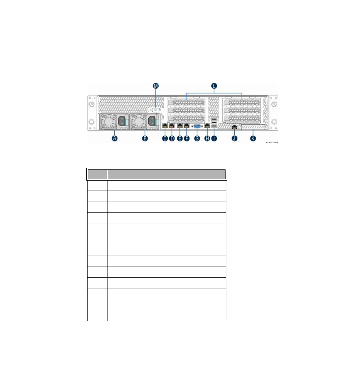
5: SGI ICE X Administration/Leader Servers
RP2 Service Node Back Panel Components
Figure 5-7 and Tab le 5-2 on page 76 identify the components on the back panel of the C2108-RP2
service node.
Figure 5-7 RP2 Service Node Back Panel Components Example
Table 5-2 RP2 Service Node Back Panel
Label Description
A Power Supply Module #1
B Power Supply Module #2
C NIC 1
D NIC 2
E NIC 3
F NIC 4
G Video connector
H RJ45 Serial-A port
I USB ports
J RMM4 NIC port
K I/O module ports/connectors (optional)
L Add-in adapter slots via Riser Card 1 and Riser Card 2
M Serial-B port (optional)
Components
76 007-5806-004
Page 97
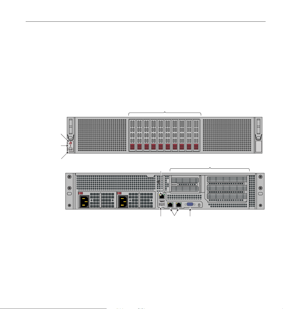
C2110G-RP5-P 2U Service Node
PCI expansion slots
!
2 1
System
reset
System
LEDs
Main
power
Ten disk drive bays
VGA
port
Ethernet
ports
USB
ports
IPMI
LAN
Figure 5-8 shows front and rear views of the SGI Rackable C2110G-RP5-P 2U service node. Note
that this server u ses up to eight DIMM memory cards, (four per pro
connect the two processors and the I/O hub in a network on the server’s motherboard. The server
has internal riser cards that support up to six optional GPU cards and also one external (non-GPU)
PCIe card at the rear of the chassis. Available numbers of GPU and PCIe option cards may be
limited by ambient temperature restrictions. Check with your SGI sales or service representative
for additional information on GPU configurations. See the SGI Rackable C2110G-RP5-P System
User Guide (P/N 007-6343-00x) for more detailed information on this 2U service node.
2U Service Nodes
cessor). Separate QPI link pairs
Figure 5-8 Front and Rear Views of the SGI C2110G-RP5-P 2U Service Node
The control panel on the C2110G-RP5-P service node provides you with system monitoring and
control. A main power button and a system reset button are located at the top of the panel. LEDs
that indicate system power is on, HDD activity, network activity, power supply status and a system
overheat/fan-fail/ UID LED are included. The C2110-RP5-P 2U server’s control panel features are
shown in Figure 5-9 and described in Table 5-3 on page 78.
007-5806-004 77
Page 98
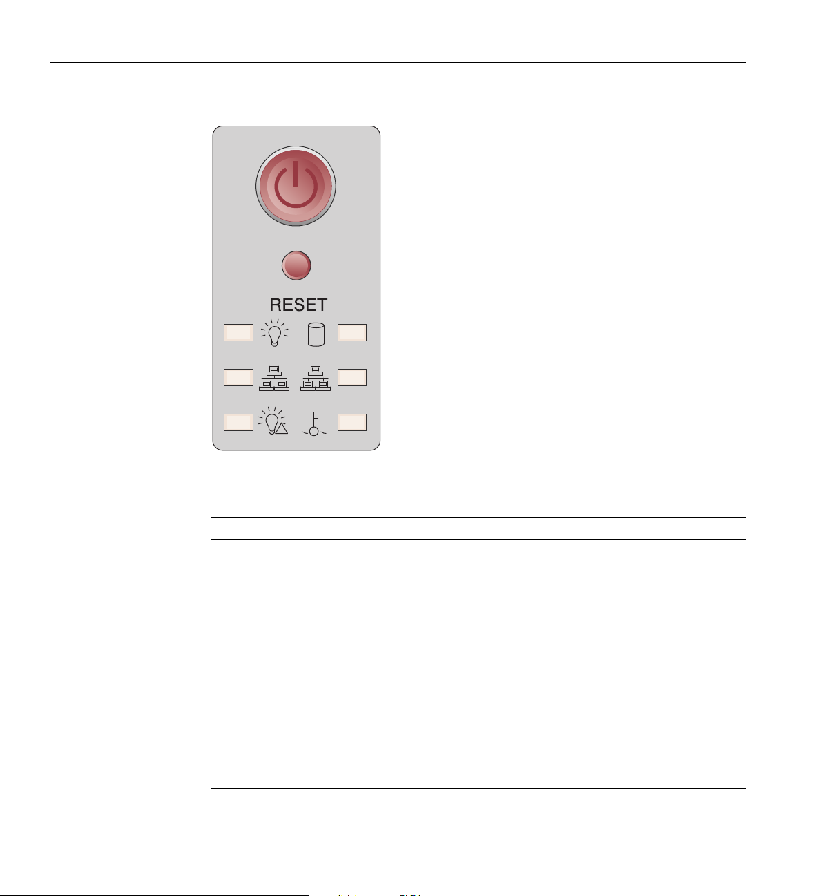
!
2 1
5: SGI ICE X Administration/Leader Servers
Figure 5-9 SGI Rackable C2110G-RP5-P 2U Service Node Control Panel Diagram
Table 5-3 C2110G-RP5-P 2U Server Control Panel Functions (listed top to bottom)
Functional feature Functional description
Power button Pressing the button applies/ removes power from the power supplies to
the server. Turning off power with this button removes main power
but keeps standby power supplied to the system.
Reset button Pressing this button reboots the server.
Power LED Indicates power is being supplied to the
Disk activity LED Indicates drive activity when f
lashing.
NIC 1 Activity LED Indicates network activity on LAN
NIC 2 Activity LED Indicates network activity on LAN
Power Fail LED
The power fail LED lights when a power supply module has failed.
Universal information LED This multi-color LED blinks red quickly to indicate a fan failure and slowly
for a power failure. A continuous solid red LED means an overheating CPU.
The LED glows/blinks solid blue when used for UID (Unit Identifier).
78 007-5806-004
server’s power supply units.
1 when flashing green.
2 when flashing green.
Page 99
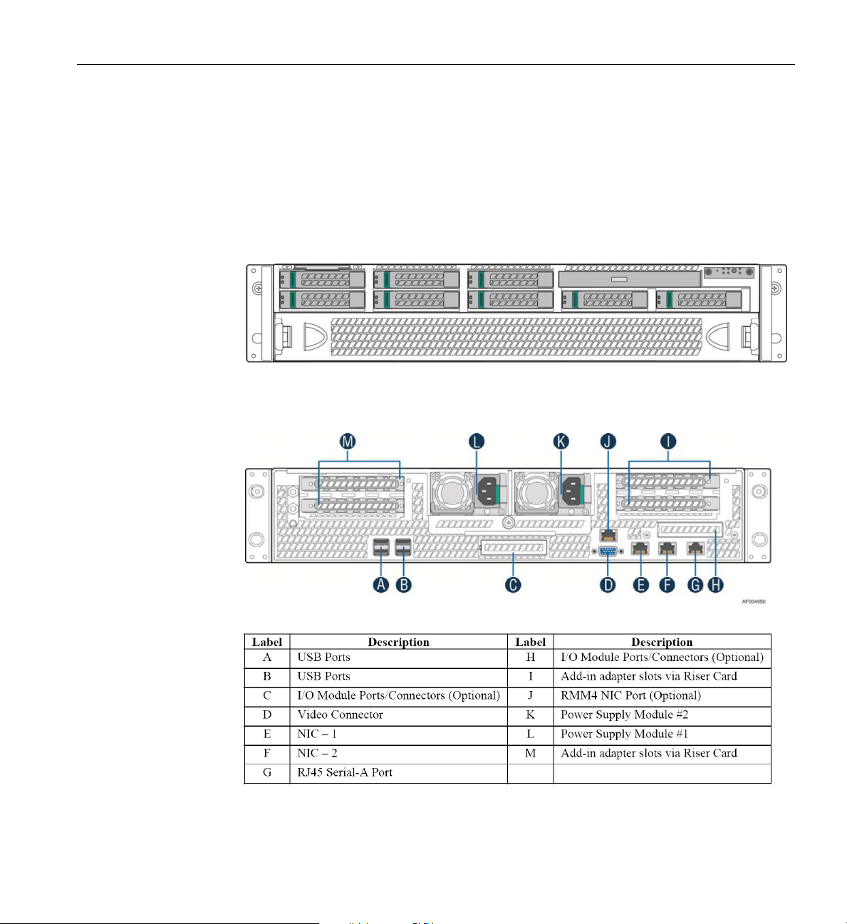
SGI UV 20 2U Service Node
The 2U-high SGI UV 20 server is available as a four-processor ICE X service node. This 2U
service node uses four Intel E5-4600 Xeon processors and supports up to 48 DIMM memory
modules plus multiple I/O modules and storage adapters. Figure 5-10 shows an example front
view of the SGI UV 20 service
components.
Figure 5-10 SGI UV 20 Service Node Front Panel Example
2U Service Nodes
node and Figure 5-11 shows and describes the unit’s rear panel
Figure 5-11 SGI UV 20 Service Node Rear Panel and Component Descriptions
007-5806-004 79
Page 100
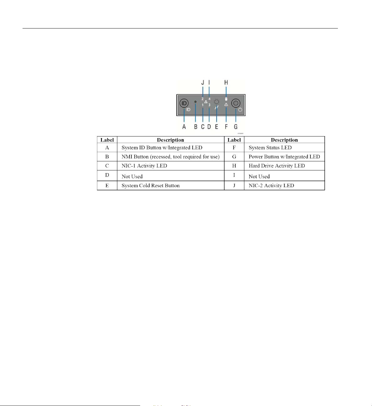
5: SGI ICE X Administration/Leader Servers
Figure 5-12 identifies and describes the functions of the SGI UV 20 service node’s front control
panel.
Figure 5-12 SGI UV 20 Service Node Front Control Panel Description
For more information on the SGI UV 20 server, see the SGI UV 20 System User Guide, (P/N
007-5900-00x).
80 007-5806-004
 Loading...