

Page 1

Silicon Graphics®550 Visual Workstation User’s Guide
007-4279-001
Page 2

CONTRIBUTORS
Written by Laraine MacKenzie, Cullen P. Vane, and Olivier Clarinval.
Edited by Connie Boltz.
Production editing by Rena Patel, Karen Jacobson.
Chapters 3 and 4 provided by Acer Incorporated
Illustrated by Dan Young
Contributions by Cullen P. Vane, Laura Cooper, Raj Mirpuri, Susan Austin, Vera Shinsky, Eileen Carter, Ellen Evlanova, Cheryl Archer, Angela
Lummel, M. Mantle, David Metzner, Patrick Heinz, Jim Pagura, Adolpho Gonzalez, Bob Sanders, Charles Alexander, Binh Dao, Paul
Davidson, D. J. Kim, Jennifer Han, Joe Hartley, J. Corchado, Tyler Vane, Zachary Vane, Craig Dunwoody, Jose Luis Serrato, Ujesh Desai, J.
Garcia.
© 2000, Silicon Graphics, Inc. All Rights Reserved.
LIMITED AND RESTRICTED RIGHTS LEGEND
Use, duplication, or disclosure by the Government is subject to restrictions as set forth in the Rights in Data clause at FAR 52.227-14 and/or in
similar orsuccessor clausesin theFAR,or inthe DOD,DOE orNASA FAR Supplements. Unpublishedrights reserved underthe CopyrightLaws
of the United States. Contractor/manufacturer is Silicon Graphics, Inc., 1600 Amphitheatre Pkwy., Mountain View, CA 94043-1351.
TRADEMARKS
Silicon Graphics is a registered trademark and SGI and the SGI logo are trademarks of Silicon Graphics, Inc. Acer is a registered trademark of
Acer Inc. Adaptec is a registered trademark of Adaptec, Inc. Linux is a registered trademark of Linus Torvalds. MS-DOS, Windows, and
Windows NT are registered trademarks of Microsoft Corporation. Novell and NetWare are registered trademarks of Novell, Inc. Sun is a
trademark of Sun Microsystems, Inc. Intel, Pentium, and Xeon are is a registered trademarks or trademarks of Intel Corporation.
The contentsof thisdocument maynot becopied orduplicated inany manner, in wholeor inpart, withoutthe priorwritten permissionof Silicon
Graphics, Inc.
This device has been tested and found to comply with the limits for a Class B digital device pursuant to Part 15 of the FCC Rules. These limits
are designed to provide reasonable protection against harmful interference in a residential installation. This device generates, uses, and can
radiate radio frequency energy and, if not installed and used in accordance with the instructions, may cause harmful interference to radio
communications.
For additional Regulatory Information, refer to the label attached to the back of the system.
Page 3

Record of Revision
Version Description
001 June 2000
Initial Rev
007-4279-001 iii
Page 4

Page 5

Contents
Figures . . . . . . . . . . . . . . . . . . . . . . . . . . ix
Tables . . . . . . . . . . . . . . . . . . . . . . . . . . xiii
About This Guide. . . . . . . . . . . . . . . . . . . . . . . xv
Obtaining Publications . . . . . . . . . . . . . . . . . . . . . xv
Reader Comments . . . . . . . . . . . . . . . . . . . . . . .xvi
1. System Setup . . . . . . . . . . . . . . . . . . . . . . . . 1
External Structure . . . . . . . . . . . . . . . . . . . . . . . 2
Internal Structure . . . . . . . . . . . . . . . . . . . . . . . 6
Pre-installation Instructions . . . . . . . . . . . . . . . . . . . . 9
Connecting External Devices. . . . . . . . . . . . . . . . . . . . 9
2. Installation of Customer Replaceable Components . . . . . . . . . . . . . 15
Pre-installation Instructions . . . . . . . . . . . . . . . . . . . . 16
Removing the Beam . . . . . . . . . . . . . . . . . . . . . 18
Replacing the Beam . . . . . . . . . . . . . . . . . . . . . 21
Removing and Installing Drives . . . . . . . . . . . . . . . . . . . 22
Removing and Installing a 5.25-inch Drive . . . . . . . . . . . . . . 22
Removing and Installing a 3.5-inch Drive in the Front-Access Drive Cage . . . . . 27
Removing and Installing a 3.5-inch Drive in the Internal Drive Cage . . . . . . . 33
Replacing the Power Supply . . . . . . . . . . . . . . . . . . . . 36
Replacing Fans . . . . . . . . . . . . . . . . . . . . . . . . 38
Replacing the Rear System Fan . . . . . . . . . . . . . . . . . . 38
Replacing the Internal Drive Cage . . . . . . . . . . . . . . . . . 40
Replacing the Front System Fan. . . . . . . . . . . . . . . . . . 42
Replacing Expansion Cards . . . . . . . . . . . . . . . . . . . . 47
Replacing the System Board . . . . . . . . . . . . . . . . . . . . 51
Replacing the I/O Panel Gasket . . . . . . . . . . . . . . . . . . . 58
007-4279-001 v
Page 6

Contents
Securing the System . . . . . . . . . . . . . . . . . . . . . . 60
Post-installation Instructions . . . . . . . . . . . . . . . . . . . . 64
3. System Board . . . . . . . . . . . . . . . . . . . . . . . . 67
Overview . . . . . . . . . . . . . . . . . . . . . . . . . 68
Processor . . . . . . . . . . . . . . . . . . . . . . . . 68
Memory. . . . . . . . . . . . . . . . . . . . . . . . . 69
System Chipsets . . . . . . . . . . . . . . . . . . . . . . 69
Expansion Slots . . . . . . . . . . . . . . . . . . . . . . 70
Hardware Management Support . . . . . . . . . . . . . . . . .70
Major Components. . . . . . . . . . . . . . . . . . . . . . . 70
System Component Installation . . . . . . . . . . . . . . . . . . . 76
ESD Precautions . . . . . . . . . . . . . . . . . . . . . . 76
Installing and Removing the Processor . . . . . . . . . . . . . . . .76
Installing and Removing Memory Modules . . . . . . . . . . . . . . 83
Installing Expansion Cards . . . . . . . . . . . . . . . . . . . 85
Error Messages . . . . . . . . . . . . . . . . . . . . . . . . 86
Software Error Messages . . . . . . . . . . . . . . . . . . . . 86
System Error Messages . . . . . . . . . . . . . . . . . . . . 87
4. Setup Utility . . . . . . . . . . . . . . . . . . . . . . . . 93
Introduction. . . . . . . . . . . . . . . . . . . . . . . . . 94
Entering Setup . . . . . . . . . . . . . . . . . . . . . . . . 94
System Information Screen . . . . . . . . . . . . . . . . . . . . 96
Product Information Screen . . . . . . . . . . . . . . . . . . . . 99
Disk Drives Screen . . . . . . . . . . . . . . . . . . . . . . 100
IDE Channel Type Screen. . . . . . . . . . . . . . . . . . . 101
Onboard Peripherals Screen . . . . . . . . . . . . . . . . . . . 104
Power Management Screen . . . . . . . . . . . . . . . . . . . 108
Boot Options Screen . . . . . . . . . . . . . . . . . . . . . 110
Date and Time Screen . . . . . . . . . . . . . . . . . . . . . 113
vi 007-4279-001
Page 7

Contents
System Security Screen . . . . . . . . . . . . . . . . . . . . .115
Supervisor Password . . . . . . . . . . . . . . . . . . . . .115
User Password . . . . . . . . . . . . . . . . . . . . . .118
Processor Serial Number. . . . . . . . . . . . . . . . . . . .119
Advanced Options Screen . . . . . . . . . . . . . . . . . . . .119
Memory/Cache Options . . . . . . . . . . . . . . . . . . . .120
PnP/PCI Options . . . . . . . . . . . . . . . . . . . . . .121
Load Default Settings Option . . . . . . . . . . . . . . . . . . .124
Abort Settings Change Option . . . . . . . . . . . . . . . . . . .125
Exit Setup . . . . . . . . . . . . . . . . . . . . . . . . .125
A. Connector Pinouts . . . . . . . . . . . . . . . . . . . . . .127
Keyboard Port . . . . . . . . . . . . . . . . . . . . . . . .128
Mouse Port . . . . . . . . . . . . . . . . . . . . . . . . .129
Video-Out Ports . . . . . . . . . . . . . . . . . . . . . . .130
DB15 HD Port . . . . . . . . . . . . . . . . . . . . . . .130
Serial Ports . . . . . . . . . . . . . . . . . . . . . . . . .131
Parallel Port . . . . . . . . . . . . . . . . . . . . . . . .132
USB Ports . . . . . . . . . . . . . . . . . . . . . . . . .133
Ethernet Port . . . . . . . . . . . . . . . . . . . . . . . .134
Audio Ports. . . . . . . . . . . . . . . . . . . . . . . . .135
Mic-In Port. . . . . . . . . . . . . . . . . . . . . . . .135
Line-In and Line-Out Ports . . . . . . . . . . . . . . . . . . .135
B. Physical Environment Specifications . . . . . . . . . . . . . . . . .137
C. Regulatory Information . . . . . . . . . . . . . . . . . . . . .139
FCC notice . . . . . . . . . . . . . . . . . . . . . . . . .139
Notice: Shield cables . . . . . . . . . . . . . . . . . . . . . .139
Notice: Peripheral devices . . . . . . . . . . . . . . . . . . . .140
Use conditions . . . . . . . . . . . . . . . . . . . . . . . .140
Notice: Canadian users . . . . . . . . . . . . . . . . . . . . .140
Remarque à l’intention des utilisateurs canadiens. . . . . . . . . . . . . .140
Important safety instructions. . . . . . . . . . . . . . . . . . . .140
007-4279-001 vii
Page 8

Contents
Laser compliance statement . . . . . . . . . . . . . . . . . . . 142
CLASS 1 LASER PRODUCT . . . . . . . . . . . . . . . . . . 142
APPAREIL A LASER DE CLASSE 1. . . . . . . . . . . . . . . . 142
LUOKAN 1 LASERLAITE LASER KLASSE 1 . . . . . . . . . . . . . 143
PRODUCTO LÁSER DE LA CLASE I . . . . . . . . . . . . . . . 143
VARO! LAVATTAESSA OLET ALTTINA LASERSÅTEILYLLE. . . . . . . . 143
Lithium battery statement . . . . . . . . . . . . . . . . . . . . 143
Index. . . . . . . . . . . . . . . . . . . . . . . . . . 145
viii 007-4279-001
Page 9

Figures
Figure 1-1 Front Bezel . . . . . . . . . . . . . . . . . 3
Figure 1-2 Rear Panel . . . . . . . . . . . . . . . . . 4
Figure 1-3 I/O Ports . . . . . . . . . . . . . . . . . 5
Figure 1-4 Internal Structure . . . . . . . . . . . . . . . 6
Figure 1-5 5.25-inch and 3.5-inch Drive Bays . . . . . . . . . . 8
Figure 1-6 Connecting AC Power Cable . . . . . . . . . . . . 10
Figure 1-7 Connecting Keyboard, Mouse, and Ethernet Cable . . . . . 11
Figure 1-8 Connecting DB15 HD Video Cable . . . . . . . . . . 12
Figure 1-9 Connecting Speakers . . . . . . . . . . . . . . 13
Figure 1-10 I/O Panel . . . . . . . . . . . . . . . . . 14
Figure 2-1 Removing Side Panel . . . . . . . . . . . . . . 17
Figure 2-2 Removing Bezel. . . . . . . . . . . . . . . . 18
Figure 2-3 Removing Beam Screw . . . . . . . . . . . . . 19
Figure 2-4 Swinging Beam from Chassis . . . . . . . . . . . . 19
Figure 2-5 Removing beam from Chassis . . . . . . . . . . . 20
Figure 2-6 Location of Beam Tab and Chassis Slot . . . . . . . . . 21
Figure 2-7 Replacing the Beam Screw. . . . . . . . . . . . . 22
Figure 2-8 Mounting Drive Rails to 5.25-inch Drives . . . . . . . . 24
Figure 2-9 Removing Bezel Blanking Plate . . . . . . . . . . . 25
Figure 2-10 Installing Bezel Blanking Plate . . . . . . . . . . . 26
Figure 2-11 Removing Drive from Drive Bay . . . . . . . . . . . 28
Figure 2-12 Detaching 3.5-inch Drive Filler Plate . . . . . . . . . . 30
Figure 2-13 Mounting Drive Rails to 3.5-inch drives . . . . . . . . . 32
Figure 2-14 Mounting Drives in the Internal Drive Cage . . . . . . . 35
Figure 2-15 Connecting Power Supply Cables . . . . . . . . . . 37
Figure 2-16 Disengaging Release Buttons and Removing Rear Fan . . . . 39
Figure 2-17 Connecting Rear Fan Cable . . . . . . . . . . . . 40
007-4279-001 ix
Page 10

Figures
Figure 2-18 . . . . . . . . . . . Location of Internal Cage Screw41
Figure 2-19 Removing the Drive Cage . . . . . . . . . . . . . 42
Figure 2-20 Removing Front Fan Screw and Releasing Clips . . . . . . 43
Figure 2-21 Removing Fan from Plastic Frame . . . . . . . . . . 44
Figure 2-22 Installing Fan into Plastic Frame . . . . . . . . . . . 45
Figure 2-23 Connecting Front Fan Cable . . . . . . . . . . . . 46
Figure 2-24 Removing Expansion Card. . . . . . . . . . . . . 48
Figure 2-25 Location of the Retaining Screw for the Expansion Slot Filler Plate . 49
Figure 2-26 Installing Expansion Card . . . . . . . . . . . . . 50
Figure 2-27 Location of System Board Screw . . . . . . . . . . . 52
Figure 2-28 Removing Retaining Bracket from System Board . . . . . . 53
Figure 2-29 Snapping Retaining Bracket onto System Board. . . . . . . 53
Figure 2-30 Positioning the System Board on Standoffs and Standoff Hooks . . 55
Figure 2-31 Location of System Board Connectors . . . . . . . . . 57
Figure 2-32 Removing I/O Panel Gasket . . . . . . . . . . . . 58
Figure 2-33 Installing I/O Panel Gasket . . . . . . . . . . . . 59
Figure 2-34 Location of Locking Loop . . . . . . . . . . . . . 61
Figure 2-35 Removing Locking Hook from its Storage Slot . . . . . . . 62
Figure 2-36 Installing Locking Loop in its Functional Slot . . . . . . . 63
Figure 2-37 Replacing Bezel . . . . . . . . . . . . . . . . 64
Figure 2-38 Placing Side Panel onto Lower Chassis Rail . . . . . . . . 65
Figure 2-39 Sliding Side Panel into Place . . . . . . . . . . . . 66
Figure 3-1 System Board Layout . . . . . . . . . . . . . . 72
Figure 3-2 Front Connector (CN29) . . . . . . . . . . . . . 75
Figure 3-3 Joint Bars . . . . . . . . . . . . . . . . . . 77
Figure 3-4 Metal Plate . . . . . . . . . . . . . . . . . 78
Figure 3-5 Fan/heatsink Module . . . . . . . . . . . . . . 79
Figure 3-6 Pentium III Xeon Processor . . . . . . . . . . . . 79
Figure 3-7 Retention Mechanism Cover . . . . . . . . . . . . 80
Figure 3-8 Unclipping Retention Mechanism Cover. . . . . . . . . 81
Figure 3-9 Plastic Ears . . . . . . . . . . . . . . . . . 82
Figure 3-10 Terminator Board . . . . . . . . . . . . . . . 83
Figure 3-11 Installing a RIMM . . . . . . . . . . . . . . . 84
x 007-4279-001
Page 11

Figures
Figure 3-12 Disengaging a RIMM . . . . . . . . . . . . . . 85
Figure 4-1 Basic Setup Utility Screen . . . . . . . . . . . . . 95
Figure 4-2 Advanced Setup Utility screen . . . . . . . . . . . 96
Figure 4-3 System Information Screen . . . . . . . . . . . . 97
Figure 4-4 Product Information Screen . . . . . . . . . . . . 99
Figure 4-5 Disk Drives Menu . . . . . . . . . . . . . . .100
Figure 4-6 IDE Drive Screen . . . . . . . . . . . . . . .102
Figure 4-7 Onboard Peripherals Screen . . . . . . . . . . . .105
Figure 4-8 Power Management Screen . . . . . . . . . . . .108
Figure 4-9 Boot Options Screen . . . . . . . . . . . . . .111
Figure 4-10 Date and Time Screen . . . . . . . . . . . . . .114
Figure 4-11 System Security Screen . . . . . . . . . . . . .115
Figure 4-12 Supervisor Password Screen . . . . . . . . . . . .116
Figure 4-13 User Password Screen . . . . . . . . . . . . . .119
Figure 4-14 Advanced Options Screen . . . . . . . . . . . . .120
Figure A-1 Keyboard Port Pinout . . . . . . . . . . . . . .128
Figure A-2 Mouse Port Pinout . . . . . . . . . . . . . . .129
Figure A-3 DB15 HD Port Pinout . . . . . . . . . . . . . .130
Figure A-4 Serial Port Pinout . . . . . . . . . . . . . . .131
Figure A-5 Parallel Port Pinout. . . . . . . . . . . . . . .132
Figure A-6 USB Port Pinout . . . . . . . . . . . . . . .133
Figure A-7 Ethernet Port Pinouts . . . . . . . . . . . . . .134
Figure A-8 Mic-In Port Pinout . . . . . . . . . . . . . . .135
Figure A-9 Line Level Port . . . . . . . . . . . . . . . .135
Figure B-1 System Dimensions . . . . . . . . . . . . . .138
007-4279-001 xi
Page 12

Page 13

Tables
Tables
Table 3-1 System Board Items . . . . . . . . . . . . . . 73
Table 3-2 System Error Messages . . . . . . . . . . . . . 87
Table 4-1 System Information Screen Parameters . . . . . . . . . 97
Table 4-2 Product Information Parameters . . . . . . . . . . .100
Table 4-3 Disk Drive Parameters . . . . . . . . . . . . . .101
Table 4-4 IDE Drive Parameters . . . . . . . . . . . . . .102
Table 4-5 Onboard Peripherals Parameters . . . . . . . . . . .105
Table 4-6 Power Management Parameters . . . . . . . . . . .109
Table 4-7 Boot Option Parameters . . . . . . . . . . . . .112
Table 4-8 Date and Time Parameters . . . . . . . . . . . .114
Table 4-9 Memory/Cache Option Parameters . . . . . . . . . .121
Table 4-10 PnP/PCI Option Parameters . . . . . . . . . . . .122
Table A-1 Keyboard Port Pinout . . . . . . . . . . . . . .128
Table A-2 Mouse Port Pinout . . . . . . . . . . . . . . .129
Table A-3 DB15 HD Port Pinout . . . . . . . . . . . . . .130
Table A-4 Serial Port Pinout . . . . . . . . . . . . . . .131
Table A-5 Parallel Port Pinout. . . . . . . . . . . . . . .132
Table A-6 USB Port Pinout . . . . . . . . . . . . . . .133
Table A-7 Ethernet Port Pinout . . . . . . . . . . . . . .134
Table A-8 Mic-in, Line-in, Line-Out Port Pinouts . . . . . . . . .135
Table B-1 Physical Environment Specifications. . . . . . . . . .137
007-4279-001 xiii
Page 14

Page 15

About This Guide
This guide provides information on using and administering a Silicon Graphics 550
Visual Workstation.
The following topics are covered in this manual:
• Chapter 1, “System Setup,” describes how to prepare the system forinstallation and
how to connect it to its peripheral devices.
• Chapter 2, “Installation of Customer Replaceable Components,” describes how to
install customer replaceable components. This includes the removal and
replacement of drives, the power supply, the fans, expansion cards, the system
board, and the I/O gasket.
• Chapter 3, “System Board,” describes the system board and all its major
components. It contains the system board layout, jumper settings, cache and
memory configurations, and information on other internal devices.
• Chapter 4, “Setup Utility,” gives information about the system BIOS and tells how
to configure the system by changing the settings of the BIOS parameters.
• Appendix A, “Connector Pinouts,” contains port pinout information for the rear
panel ports.
• Appendix B, “Physical Environment Specifications,” details the physical
environment specifications for the Silicon Graphics 550 Visual Workstation system.
• Appendix C, “Regulatory Information,” provides regulatory information.
For general information about SGI Visual Workstations, consult
http://www.sgi.com/workstations.
Obtaining Publications
To obtain SGI documentation, go to the SGI Technical Publications Library at
http://techpubs.sgi.com.
007-4279-001 xv
Page 16

About This Guide
Reader Comments
If you have comments about the technical accuracy, content, or organization of this
document, pleasetell us. Be sure to includethe title and document numberof the manual
with your comments. (Online, the document number is located in the front matter of the
manual. In printed manuals, the document number can be found on the back cover.)
You can contact us in any of the following ways:
• Send e-mail to the following address:
• Use the Feedback option on the Technical Publications Library World Wide Web
page:
http://techpubs.sgi.com
• Contact your customer service representative and ask that an incident be filed in the
SGI incident tracking system.
• Send mail to the following address:
Technical Publications
SGI
1600 Amphitheatre Pkwy., M/S 535
Mountain View, California 94043-1351
• Send a fax to the attention of “Technical Publications” at +1 650 932 0801.
We value your comments and will respond to them promptly.
xvi 007-4279-001
Page 17

Chapter 1
1. System Setup
This chapter details the steps required to install a Silicon Graphics 550 Visual
Workstation. It describes how to prepare the system for installation and how to connect
it to its peripheral devices. It also provides a general description of the external and
internal structure of the Silicon Graphics 550 Visual Workstation.
007-4279-001 1
Page 18

1: System Setup
External Structure
This sectiondescribes the external featuresof the system housing(the front bezel andthe
rear panel).
• Front Bezel
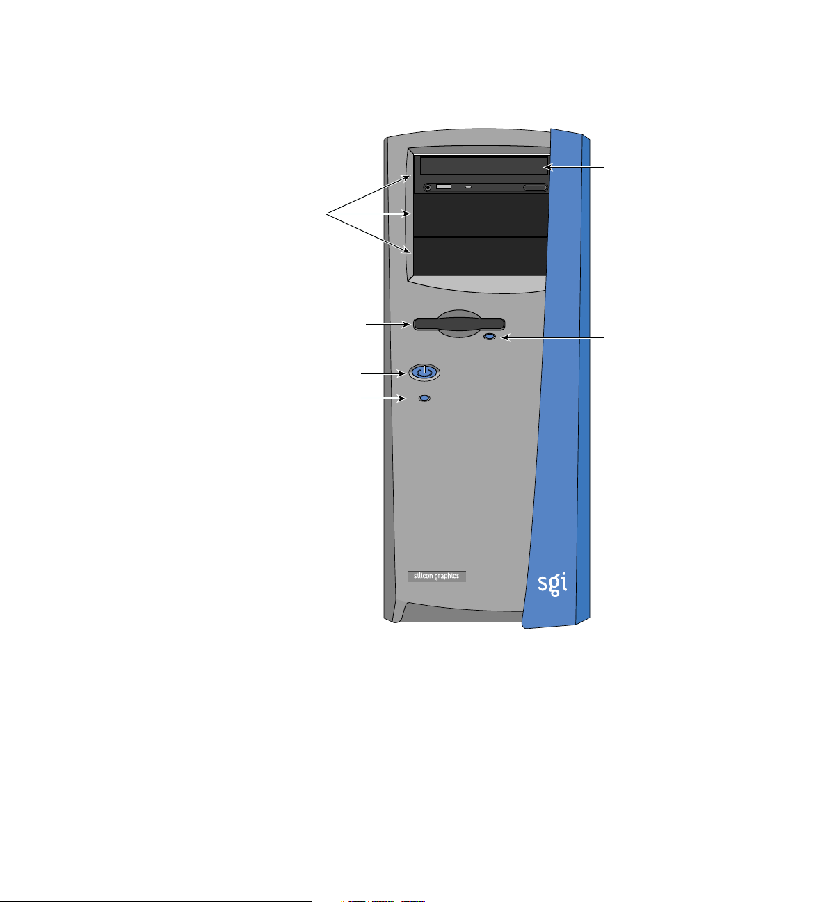
As illustrated in Figure 1-1, the floppy drive and up to three 5.25-inch devices are
accessible from the front panel. The top 5.25-inch drive bay is occupied by a
CD-ROM drive. The power switch, the reset button, and the floppy disk ejectbutton
are also located on the front bezel.
2 007-4279-001
Page 19
5.25" drive bays
External Structure
CD-ROM drive
Floppy drive
Power button
Reset button
Floppy disk
eject button
Figure 1-1 Front Bezel
• Rear Panel
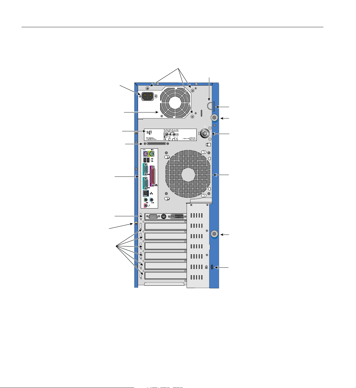
As shown in Figure 1-2, the rear panel includes the AC power input socket, the rear
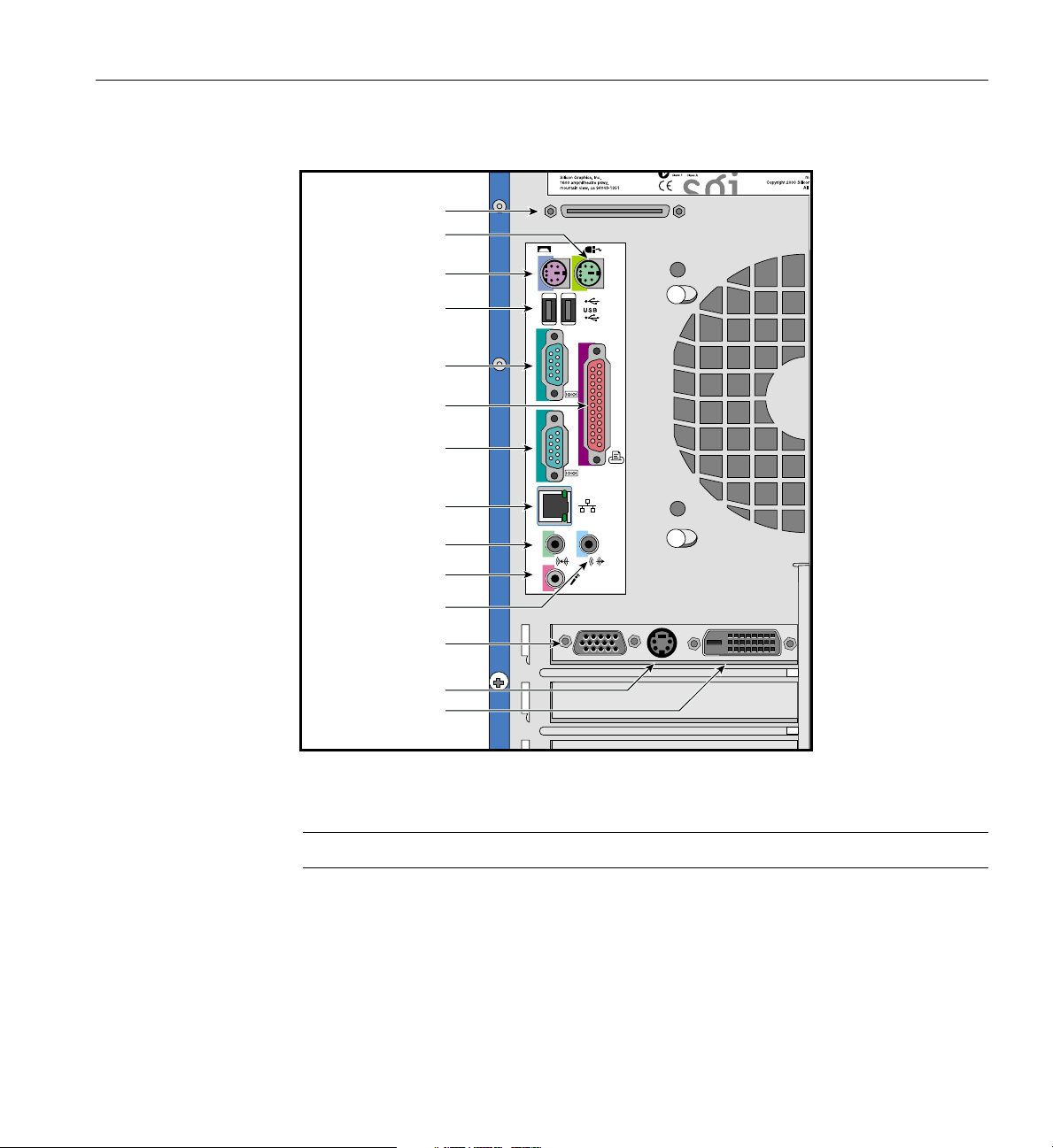
system fans, six expansion slots, and the I/O panel. Figure 1-3 shows a detailed
view of the I/O panel.
007-4279-001 3
Page 20
1: System Setup
Power supply
rear screws
Locking loop
AC power
input socket
Power supply
fan
System label
External SCSI
I/O panel
Video-Out
port
System
board screw
Expansion
slots
Locking loop slot
Side panel
retaining screw
Key lock
1
2
2
1
Rear fan
Side panel
retaining screw
Kensington
lock slot
Figure 1-2 Rear Panel
4 007-4279-001
Page 21
External SCSI
Mouse port
Keyboard port
USB ports
Serial port 1
Parallel port
Serial port 2
Ethernet port
Audio-In port
MIC In port
External Structure
1
2
2
1
Line-Out port
Monitor port
S-Video-Out port
DVI-D-port
Figure 1-3 I/O Ports
Note: The DVI-D port is optional, depending on your graphics card.
007-4279-001 5
Page 22
1: System Setup
Internal Structure
Power
supply
Lock
Tamper switch
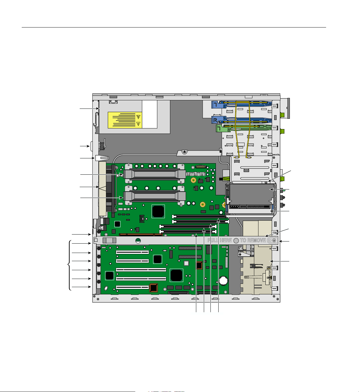
This section describes the location of the main components inside the Silicon Graphics
550 Visual Workstation chassis as illustrated in Figure 1-4.
Rear fan
AGP 4X slot
PCI slots
CPU
CPU
Internal
cage screw
Internal
drive cage
System
disk
Beam
Beam screw
Front fan
assembly
Memory sockets
Figure 1-4 Internal Structure
6 007-4279-001
Page 23

Internal Structure
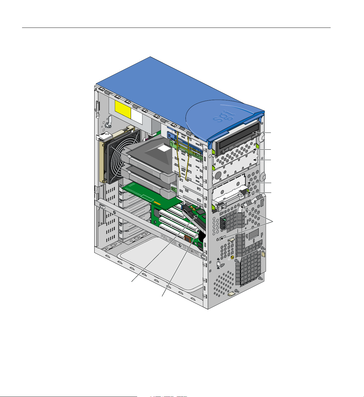
• The Silicon Graphics 550 Visual Workstation has three 5.25-inch and four 3.5-inch
drive bays, as shown in Figure 1-5. All three 5.25-inch drive bays are externally
accessible from the front panel. Two of the 3.25-inch drive bays are located on the
front panel (behind the bezel)—the other two are housed and accessible inside the
chassis.
• The Silicon Graphics 550 Visual Workstation is cooled by three fans—one front
system fan and two rear system fans (see Figure 1-4). The front fan pulls the cool air
into the chassis, while the two rear fans pull the warm air out of the chassis. One
rear fan is located on the rear panel; the other rear fan is located in the power
supply.
• The power supply is auto-switching for 110V or 220V AC power. The power supply
converts AC power to DC voltages which are used by the system board, the fans,
and the 3.5-inch and 5.25-inch drives. It is located above the system board on the
rear panel.
• The system board is mounted parallel to the right side panel. For an overview of the
system board and its components, see Chapter 3, “System Board”.
007-4279-001 7
Page 24
1: System Setup
5.25" drive bay
(CD-ROM drive installed)
5.25" drive bay
5.25" drive bay
3.5" drive bay
3.5" drive bay
(floppy disk drive
installed)
Drive sled
screws
Internal 3.5"
drive slot
Internal 3.5"
drive bay
(hard disk drive installed)
Figure 1-5 5.25-inch and 3.5-inch Drive Bays
8 007-4279-001
Page 25

Pre-installation Instructions
Before proceeding with theinstallation, select asuitable site that willallow for continued
maximum performance of the unit, and for easy access to its components.
Consider the following questions before selecting a site for the system:
• Will the intended location allow for convenient access to areas of routine
procedures, such as the power switch, the drive bays, and the rear panel
connectors?
• Is the intended location free of dust, spills, or any other condition inappropriate for
a high-performance computing system?
• Will the system be stable and free from vibration?
• Is the intended location well-ventilated and away from any source of heat? For the
cooling system to perform properly, it is essential that the system be located in an
area where airflow is unrestricted. Refer to Appendix B, “Physical Environment
Specifications” for physical environment specifications.
Pre-installation Instructions
Connecting External Devices
Follow the instructions in this section to connect the system to the power source and to
its external peripheral devices.
007-4279-001 9
Page 26
1: System Setup
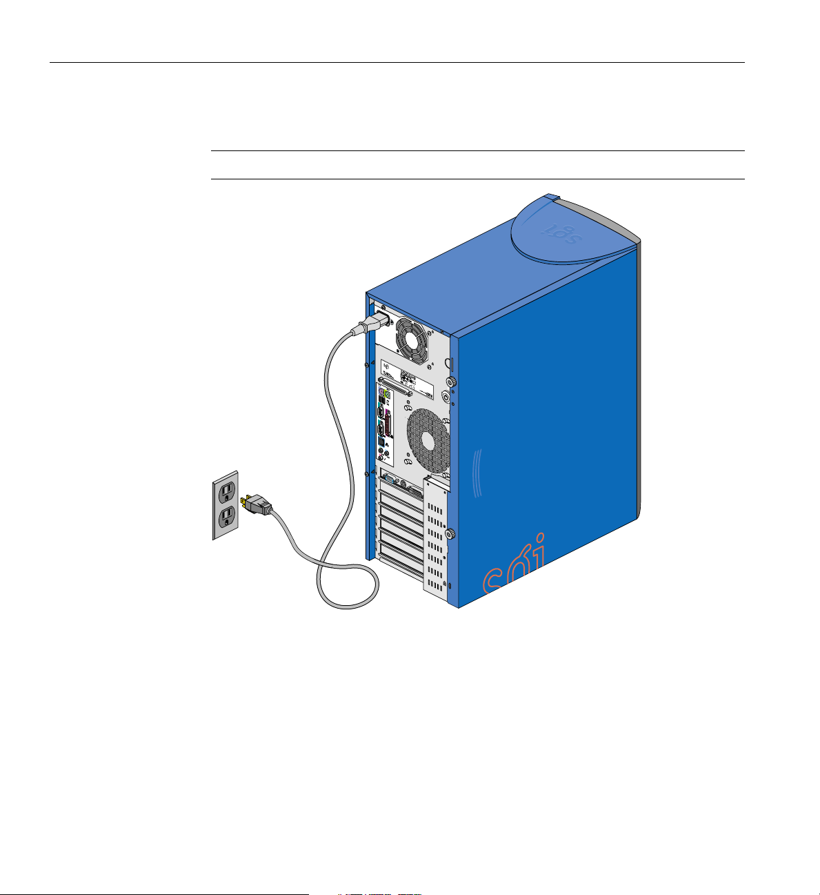
1. Connect the AC power cable to the system as shown in Figure 1-6.
Caution: Always use a grounded electrical outlet.
1
2
2
1
Figure 1-6 Connecting AC Power Cable
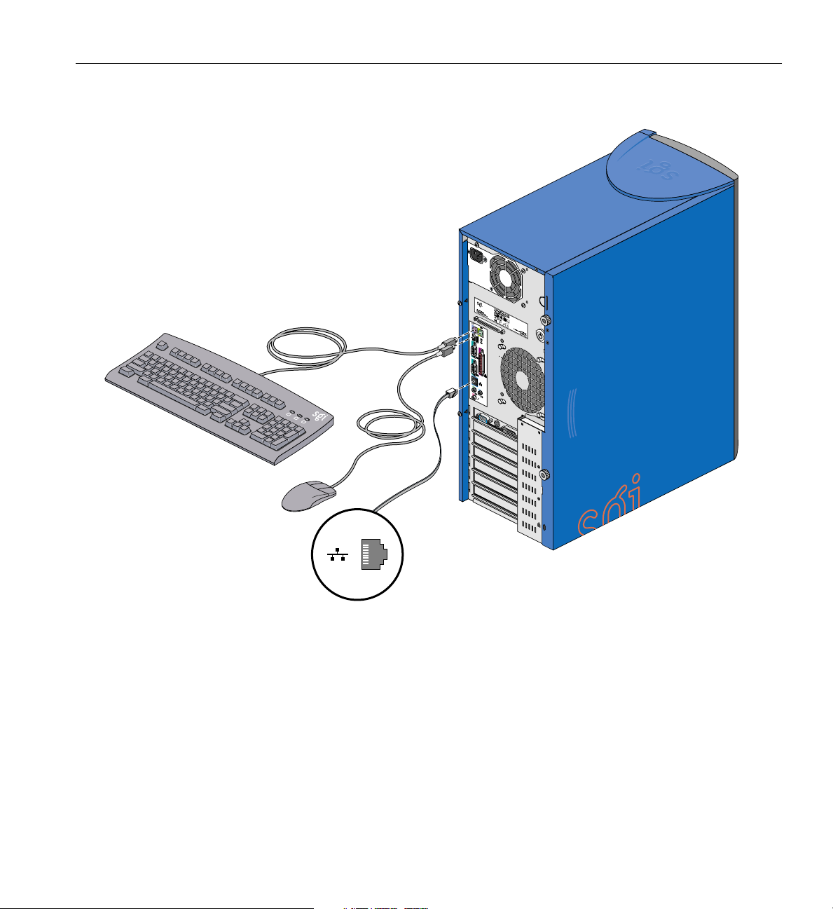
2. Connect the keyboard and mouse to the system as shown in Figure 1-7.
3. Connect the Ethernet cable to the system as shown in Figure 1-7. The built-in
Ethernet port is designed for use with 10-Base-T or 100-Base-TX Ethernet networks
and will automatically switch to the proper speed.
10 007-4279-001
Page 27
Connecting External Devices
1
2
2
1
Figure 1-7 Connecting Keyboard, Mouse, and Ethernet Cable
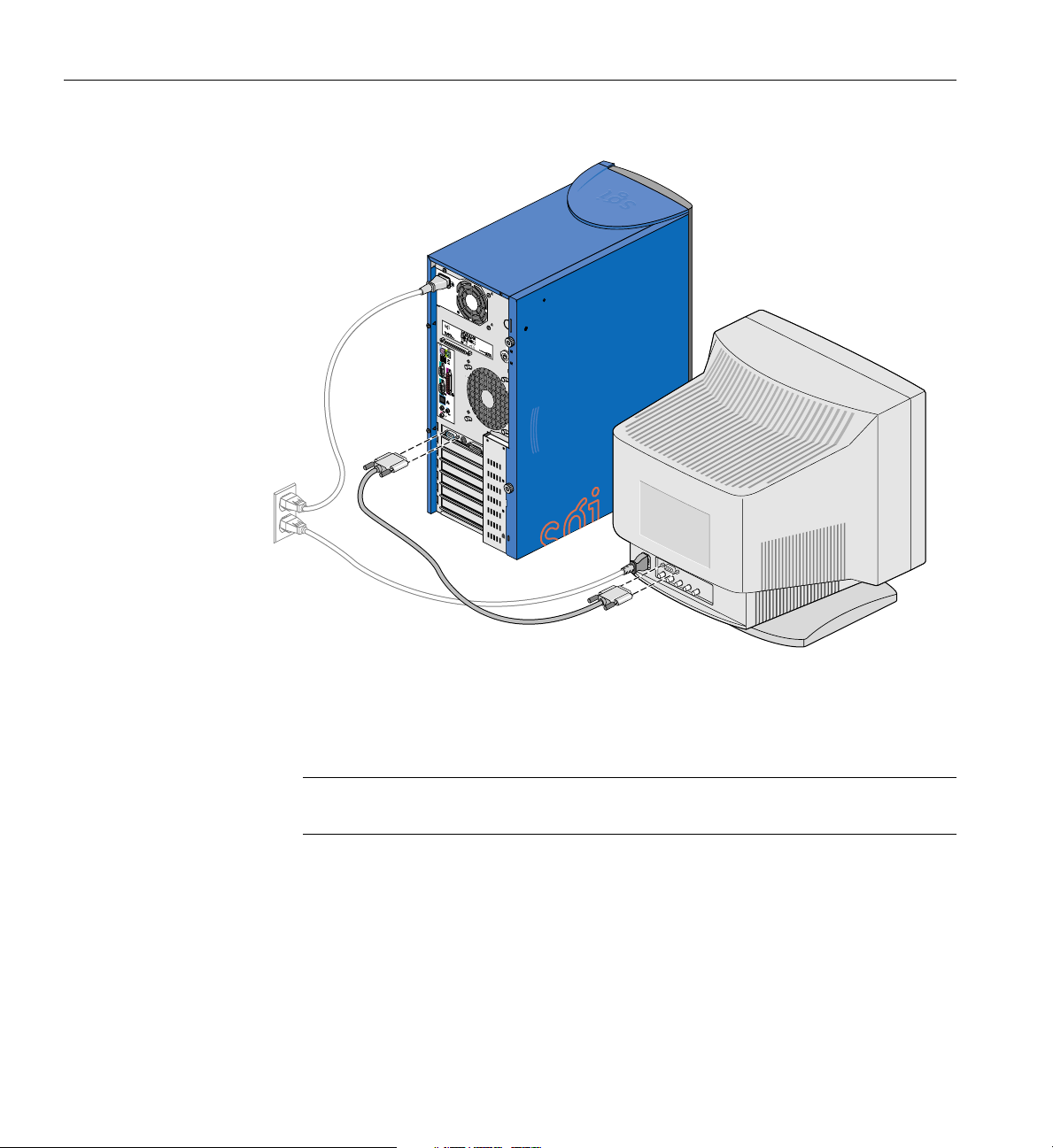
4. Connect a DB15 HD video cable to the system as shown in Figure 1-8.
5. Connect the monitor to the power source as shown in Figure 1-8.
007-4279-001 11
Page 28
1: System Setup
1
2
2
1
Figure 1-8 Connecting DB15 HD Video Cable
6. Follow these directions to connect speakers to the system. Figure 1-9 illustrates the
procedure:
Note: Speakers on your Silicon Graphics 550 Visual Workstation may be an optional
feature.
a. Connect the power cable to the right speaker (the speaker with control buttons
and four ports).
b. Connect the right speaker to the system by plugging the cable into the system
line-out port and the speaker input signal port. Refer to Figure 1-10 for the
location of the line-out port.
c. Connect the right speaker to the left speaker, as shown in Figure 1-9.
12 007-4279-001
Page 29
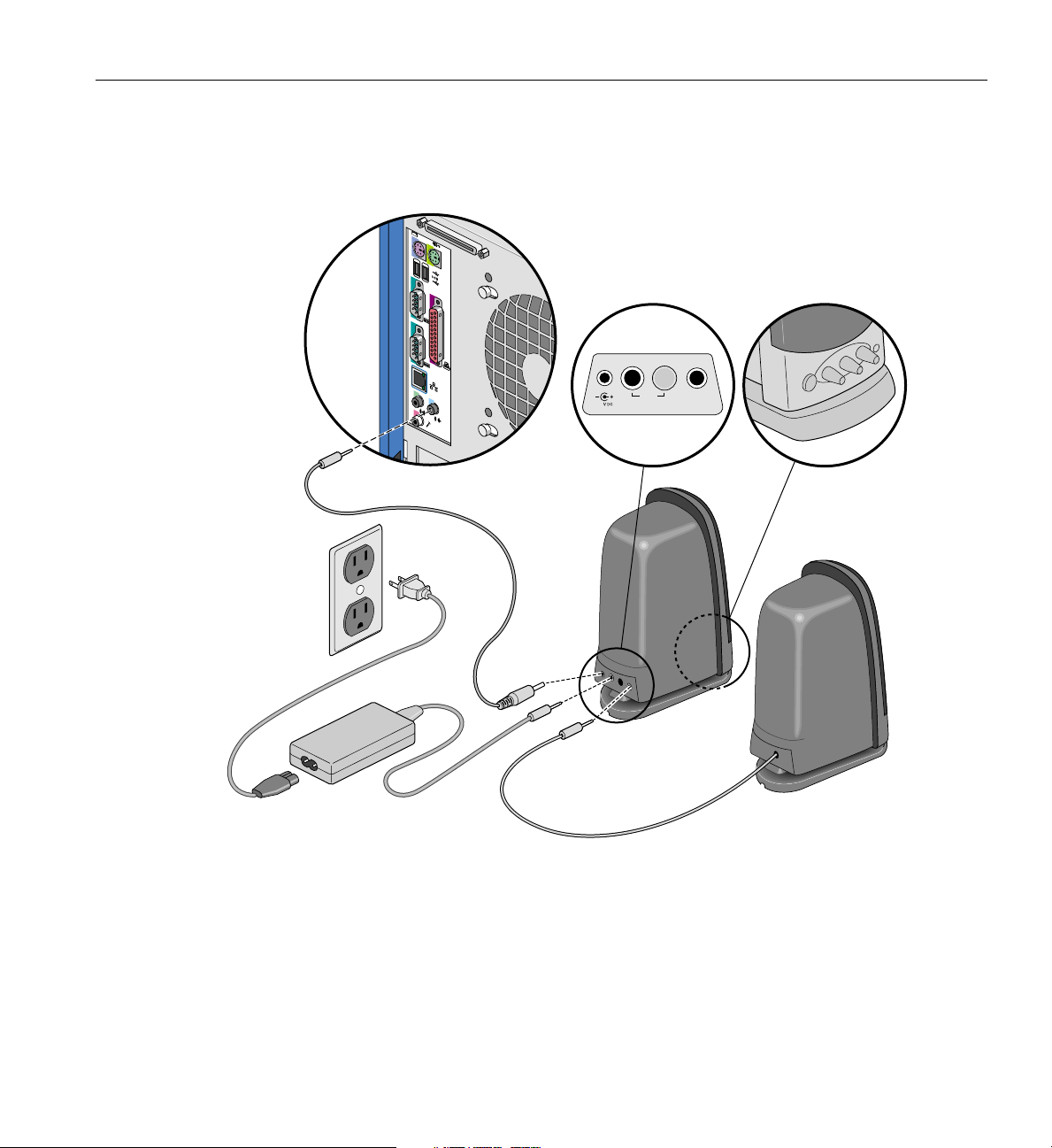
Connecting External Devices
d. Plug the speaker power supply into an AC power outlet.
1
2
2
1
Input Signal
Output
Left speaker
18.5
Subwoofer
Figure 1-9 Connecting Speakers
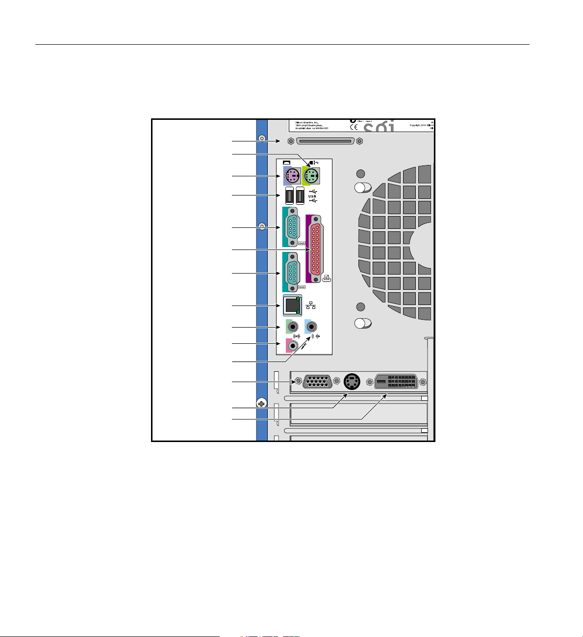
7. Connect other external devices to their respective ports. Refer to Figure 1-10 for a
detailed view of the I/O panel.
007-4279-001 13
Page 30
1: System Setup
External SCSI
Mouse port
Keyboard port
USB ports
Serial port 1
Parallel port
Serial port 2
Ethernet port
1
2
2
1
Audio-In port
MIC In port
Line-Out port
Monitor port
S-Video-Out port
DVI-D-port
Figure 1-10 I/O Panel
8. To turn on the system, press the power switch on the front panel (see Figure 1-1).
14 007-4279-001
Page 31

Chapter 2
2. Installation of Customer Replaceable Components
This chapter describes how to install customer replaceable components. This includes
the removal and replacement of the beam, 3.5-inch and 5.25-inch drives, the power
supply, the fans, expansion cards, thesystem board, andthe I/O gasket.A description of
the steps to be taken to prepare the system for installation is provided first. The
installation of memory modules and a CPU is described in Chapter 3.
007-4279-001 15
Page 32

2: Installation of Customer Replaceable Components
Pre-installation Instructions
The following steps describe how to prepare the system for the removal and installation
of customer replaceable components:
1. Turn off the system before opening the side panel. To turn off the system, hold
down the power button for four seconds.
2. Unplug the AC power cable from the wall socket and from the power supply.
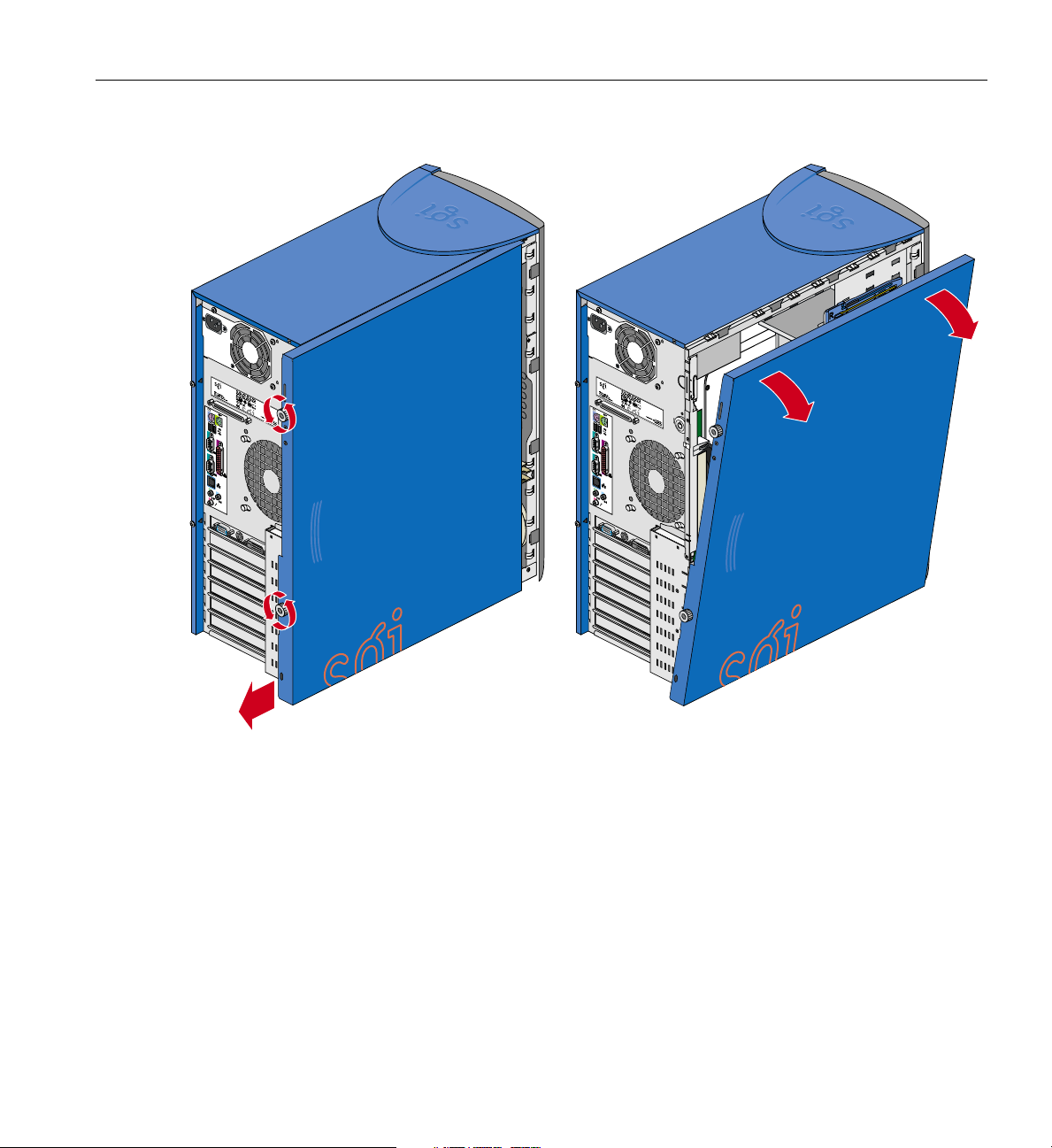
3. Follow these instructions to remove the side panel, as shown in Figure 2-1:
a. Unscrew the two thumbscrews on the back of the case.
b. Slide the panel toward the rear of the chassis.
c. Lift the panel up and away from the chassis.
16 007-4279-001
Page 33
Pre-installation Instructions
1
2
2
1
1
2
2
1
Figure 2-1 Removing Side Panel
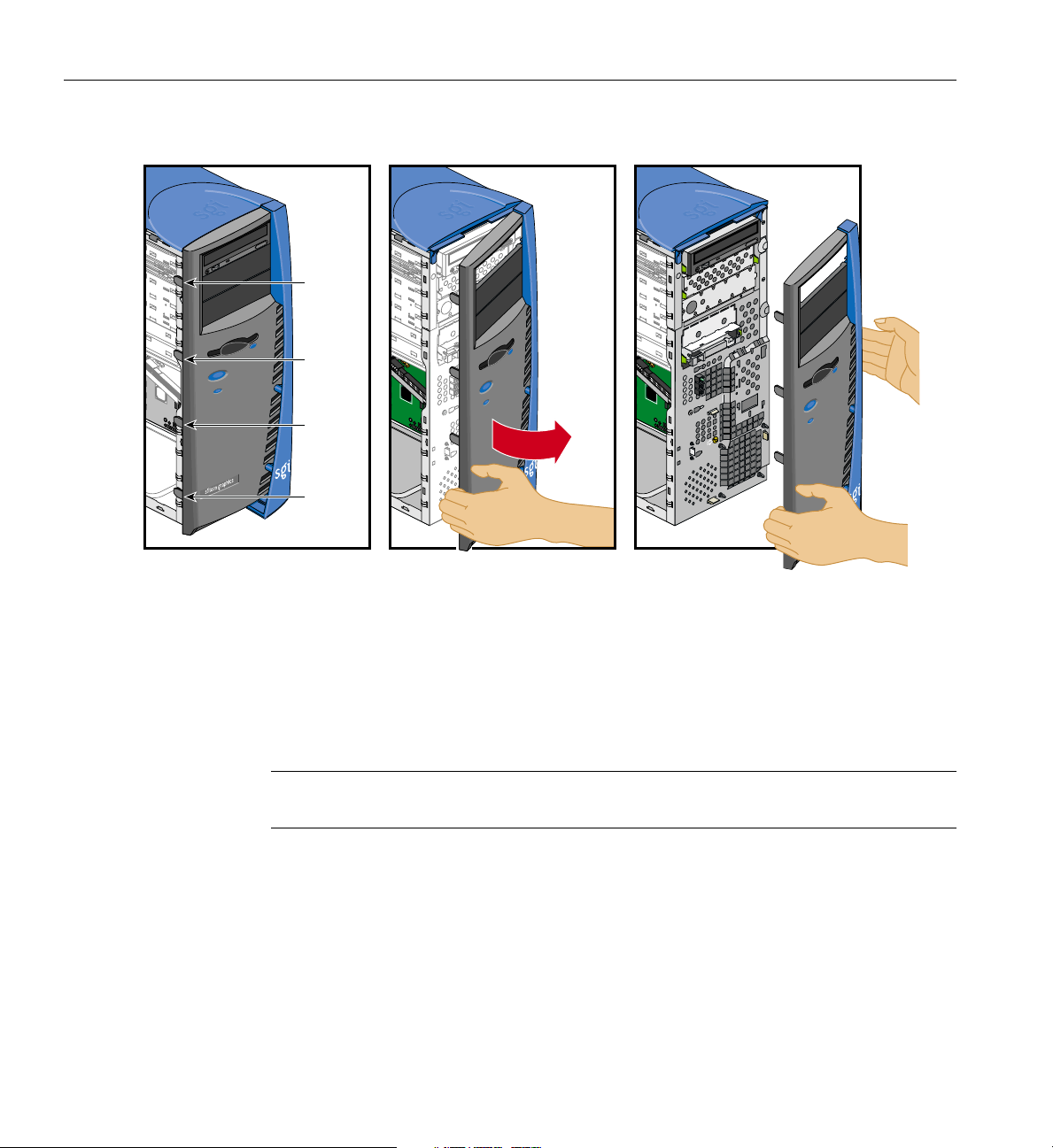
4. If you will need access to the front panel drives, you will have to remove the bezel.
Follow these instructions if you need to remove the bezel:
a. Remove the side panel as explained in Step 3.
b. Release the four tabs on the side of the bezel by gently lifting them out of the
chassis while at the same time pulling the bezel away from the system.
Figure 2-2 illustrates the procedure.
c. After the four tabs are released, rotate the bezel away from the chassis.
007-4279-001 17
Page 34
2: Installation of Customer Replaceable Components
Tab
Tab
Tab
Tab
Figure 2-2 Removing Bezel
Removing the Beam
The following steps describe how to remove the beam from the chassis. Removing the
beam will allow easier access to components within the chassis.
Note: You should never run your Silicon Graphics 550 Visual Workstation without the
beam installed.
1. Remove the side panel as described in “Pre-installation Instructions” on page 16.
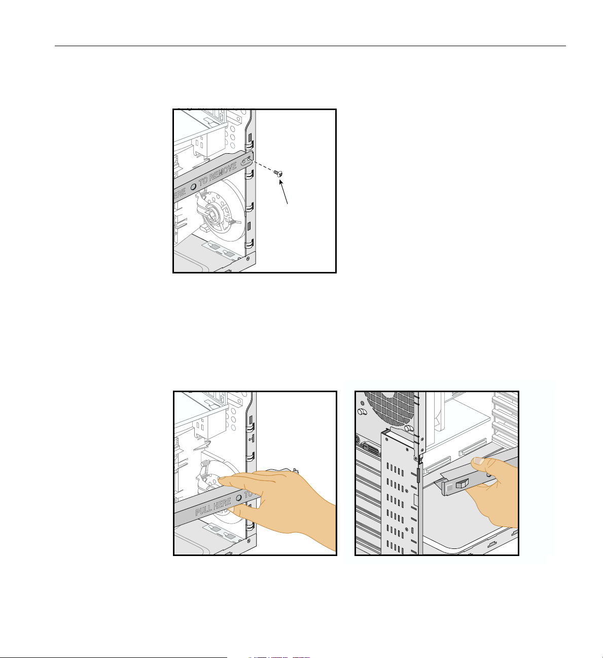
2. Remove the beam screw located on the right side of the beam. Figure 2-3 shows the
location of the screw.
18 007-4279-001
Page 35
Pre-installation Instructions
Beam screw
Figure 2-3 Removing Beam Screw
3. To remove the beam from the chassis, gently pull the right side of the beam from the
chassis (the beam is marked “Pull Here for Removal”). This will unlock the beam.
4. Swing the right side of the beam away from the chassis. Figure 2-4 shows how to
swing the beam from the chassis.
Figure 2-4 Swinging Beam from Chassis
007-4279-001 19
Page 36
2: Installation of Customer Replaceable Components
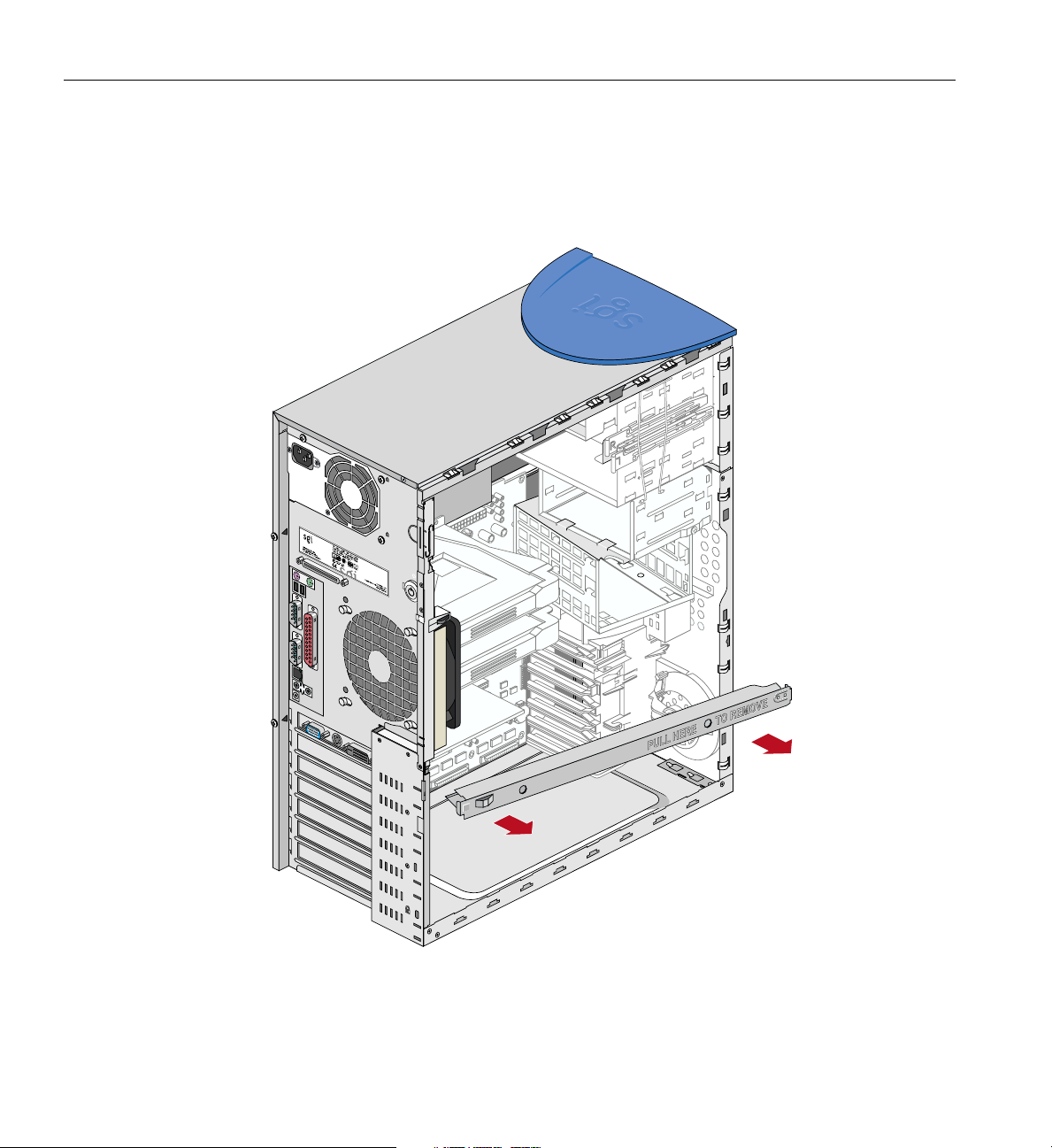
5. After the beam is clear of the chassis, pull the beam off of the slot located on the left
side of the chassis. Figure 2-5 shows how to completely remove the beam from the
chassis.
1
2
2
1
Figure 2-5 Removing beam from Chassis
20 007-4279-001
Page 37
Replacing the Beam
Chassis slot
Pre-installation Instructions
The following steps describe how to replace the beam in the chassis.
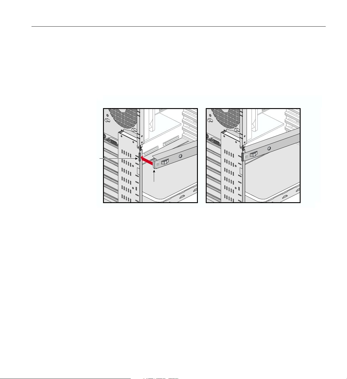
1. Hook the tab located on the left side of the beam into the slot in the chassis.
Figure 2-6 shows the location of the beam’s tab and the chassis’ slot.
Beam tab
Figure 2-6 Location of Beam Tab and Chassis Slot
2. Swing the beam towards the chassis until the tab on the right side of the beam fits
into the slot on the right side of the chassis. Figure 2-6 shows the location of these
tabs and slots.
3. Insert the right hand tab on the beam into the slot on the chassis and gently push the
tab into the slot until the tab locks into the chassis.
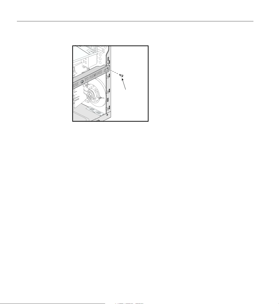
4. Replace the beam screw in the beam. Figure 2-7 shows the location of the screw.
007-4279-001 21
Page 38
2: Installation of Customer Replaceable Components
Figure 2-7 Replacing the Beam Screw
Removing and Installing Drives
Beam screw
This section covers the removal and installation of 5.25-inch and 3.5-inch drives in the
drive bays.
Removing and Installing a 5.25-inch Drive
The following instructions describe how to remove 5.25-inch drives:
1. Remove the side panel and the bezel as described in “Pre-installation Instructions”
on page 16.
2. Disconnect all cables from the rear of the drive to be removed.
3. To remove the drive from a drive bay, press the drive rail plastic release tabs on both
sides of the drive and pull the drive out of the chassis. Figure 2-11 on page 28
illustrates the procedure (Figure 2-11 illustrates removal of a 3.5-inch drive, but the
removal of 5.25-inch is similar).
4. To remove a driverail from the drive, pull therail away from the drive bylifting one
end of the rail.
22 007-4279-001
Page 39

Removing and Installing Drives
Any empty 5.25-inchdrive baysshould becovered witha drivefiller plate.The following
instructions describe how to remove and install 5.25-inch drive bay filler plates:
• To remove a drive filler plate, insert a finger into the hole on the filler plate and pull
it out of the chassis.
• To install a drive filler plate in an empty drive, insert and push the filler plate into
the drive bay until the drive filler plate snaps into place.
The following instructions describe how to install 5.25-inch drives:
1. All drives are mounted on snap-on drive rails. The Silicon Graphics 550 Visual
Workstation comes with two sets of spare 5.25-inch drive rails. The spare drive rails
are located inside the chassis on the side of the 5.25-inch drive bays.
2. The drive rails for the 5.25-inch drives are interchangeable—they do not have ‘R’ or
‘L’ markings that indicate which side they have to be mounted on. Any unmarked
drive rail can be mounted on either side of the drive.
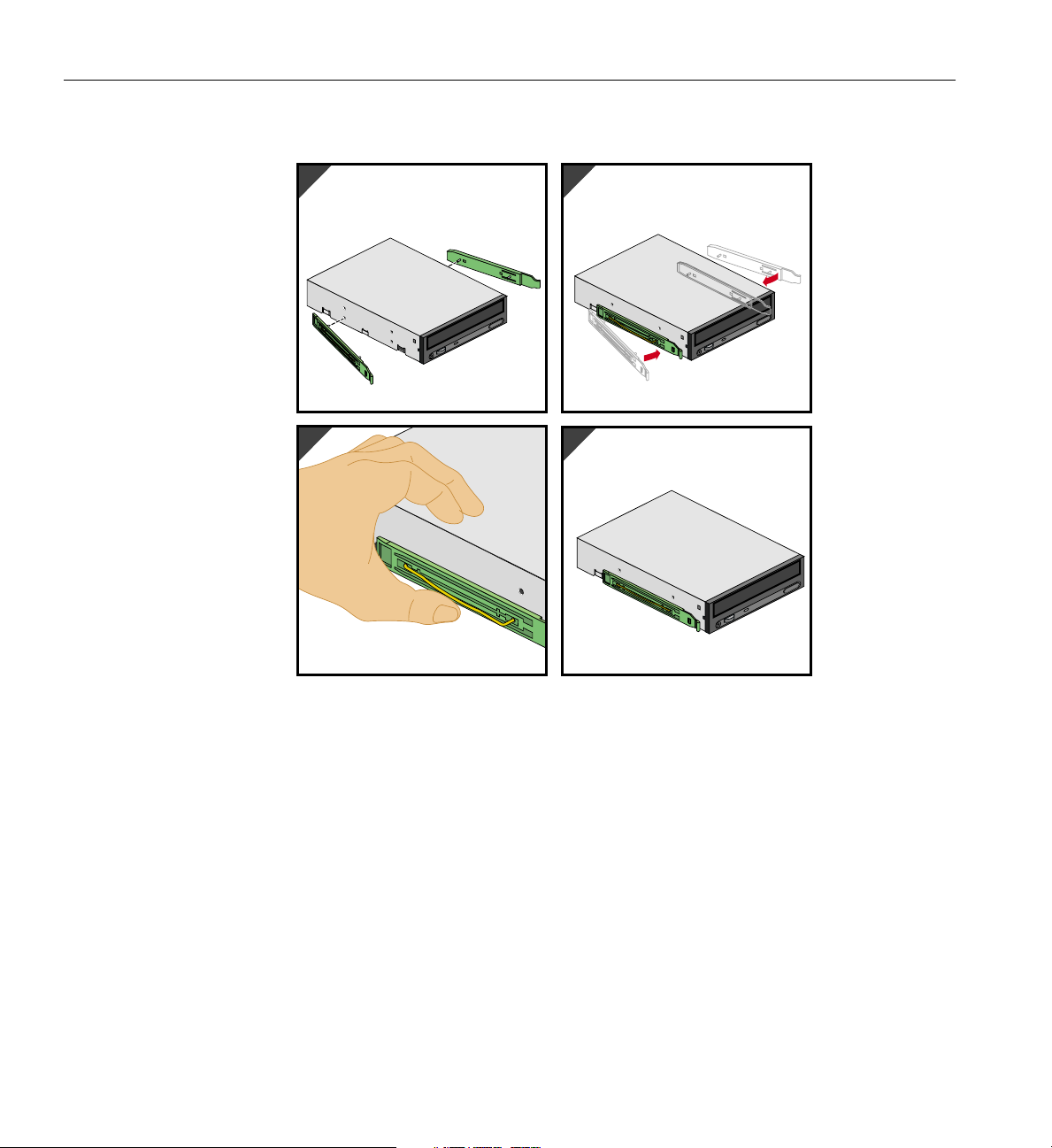
3. To mount a drive rail to the drive, place one end of the drive rail wire clip into its
drive screw hole. Gently push on the middle of the drive rail until the other end of
the wire clip snaps into its screw hole. Figure 2-8 illustrates the procedure.
007-4279-001 23
Page 40
2: Installation of Customer Replaceable Components
1
34
2
Figure 2-8 Mounting Drive Rails to 5.25-inch Drives
4. To mount a 5.25-inch drive in the drive cage, place the drive in the selected drive bay
and slide the drive into the bay until the rails snap into place.
5. Connect cables to the drive.
6. The Silicon Graphics 550 Visual Workstation comes with two plastic blanking plates
installed on the bezel. The following directions show how to remove and install the
bezel blanking plates:
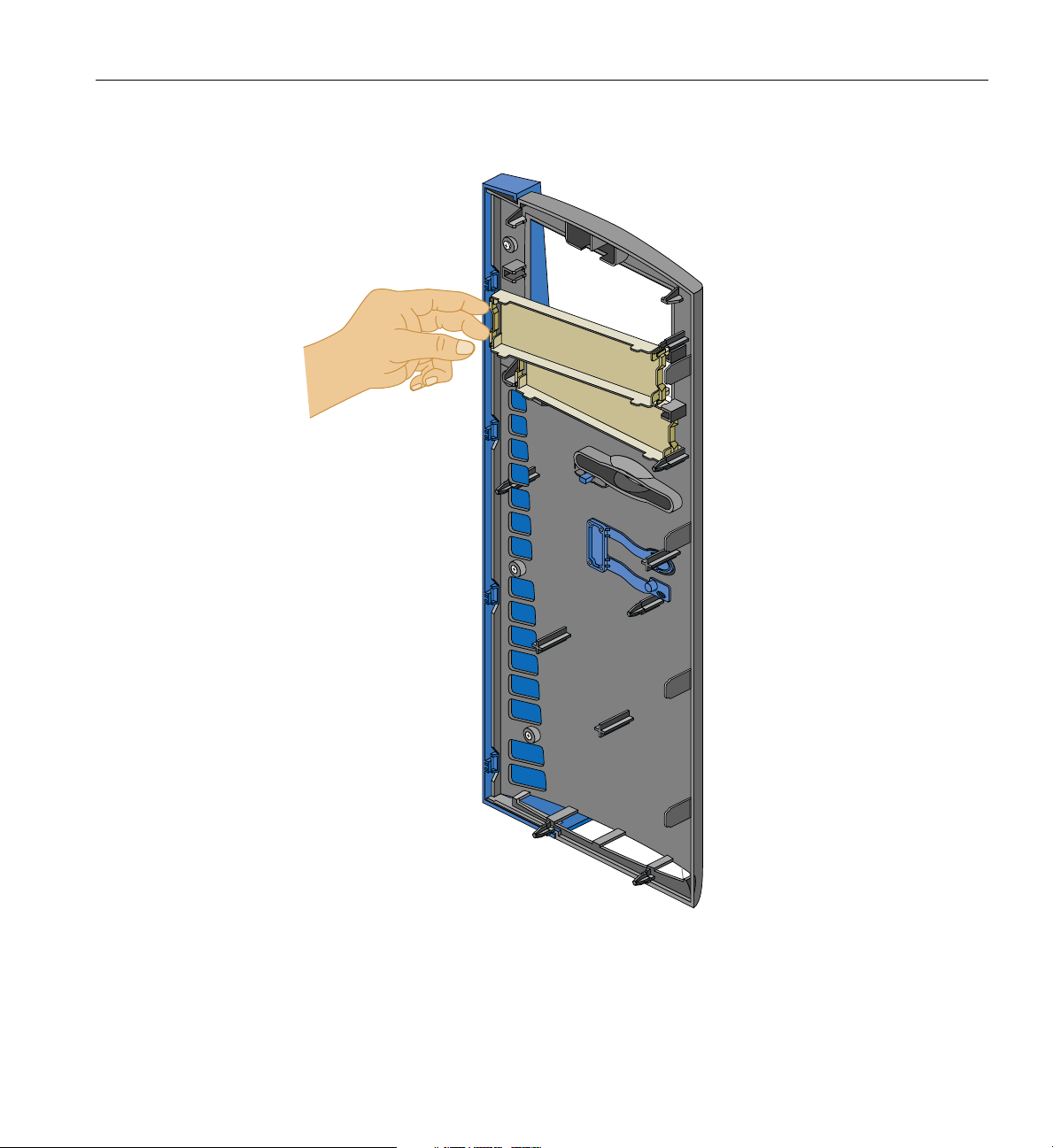
• To remove a blanking plate, push on the release mechanism at one end of the
blanking plate and pull the blanking plate out of the bezel. Figure 2-9 illustrates
the procedure.
24 007-4279-001
Page 41
Removing and Installing Drives
Figure 2-9 Removing Bezel Blanking Plate
007-4279-001 25
Page 42
2: Installation of Customer Replaceable Components
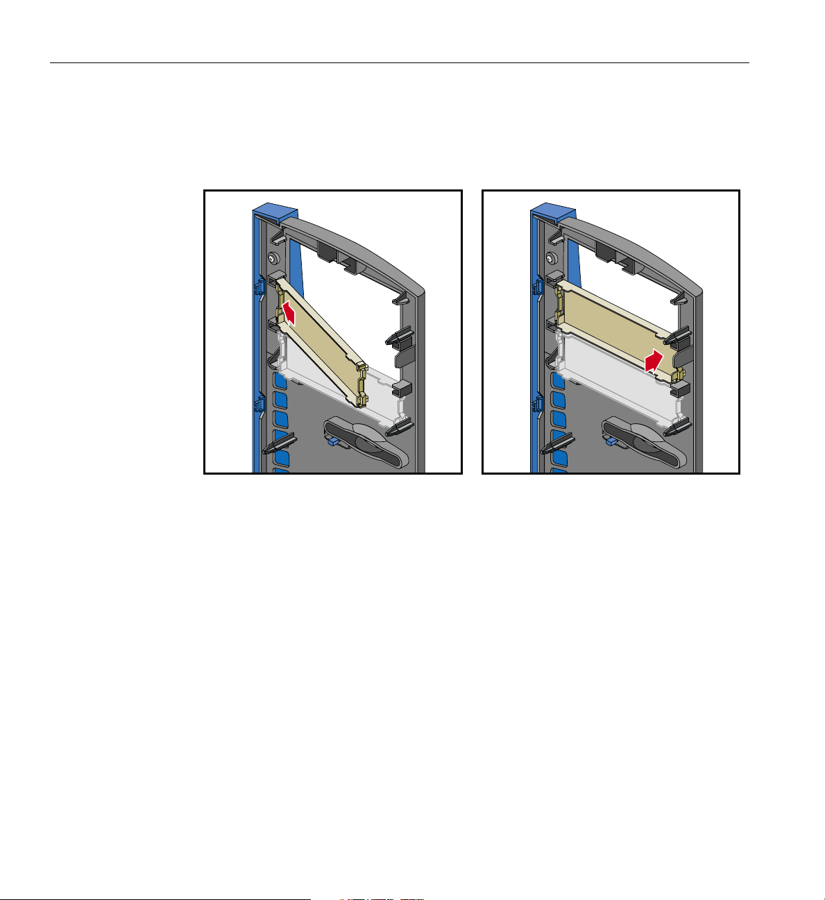
• To install a blanking plate, insert one end of the blanking plate into its retaining
notches, then push the other end until it snaps into place. See Figure 2-10 for an
illustration of the procedure.
Figure 2-10 Installing Bezel Blanking Plate
7. Replace the bezel and the side panel as described in “Post-installation Instructions”
on page 64.
26 007-4279-001
Page 43

Removing and Installing Drives
Removing and Installing a 3.5-inch Drive in the Front-Access Drive Cage
The following instructions describe how to remove 3.5-inch drives from the front-access
drive cage:
1. Remove the side panel and the bezel as described in “Pre-installation Instructions”
on page 16.
2. Disconnect all cables from the rear of the drive to be removed.
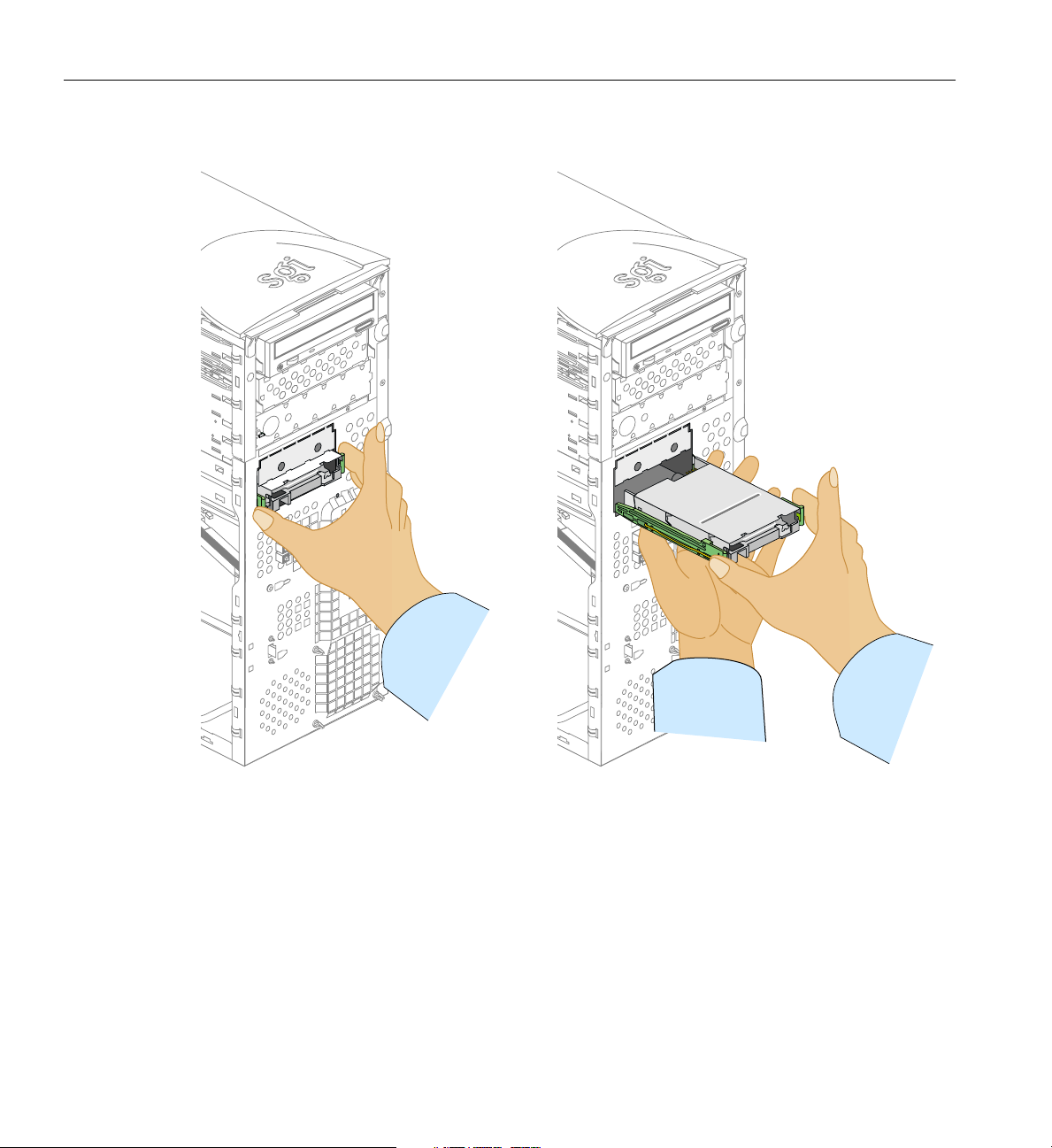
3. To remove the 3.5-inchdrive from a drive bay, press thedrive rail plastic release tabs
on both sides of the drive andpull the drive out of the chassis. Figure 2-11 illustrates
the procedure.
007-4279-001 27
Page 44
2: Installation of Customer Replaceable Components
Figure 2-11 Removing Drive from Drive Bay
4. To remove a driverail from the drive, pull therail away from the drive bylifting one
end of the rail.
28 007-4279-001
Page 45

Removing and Installing Drives
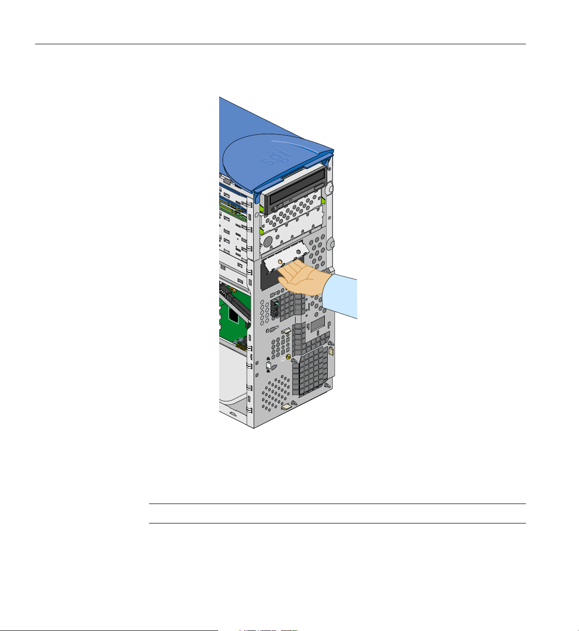
The upper3.5-inch front access drivebay is covered witha detachable fillerplate. Follow
these instructions to detach the filler plate:
Note: Once removed, the filler plate cannot be re-installed.
• The lower 3.5-inch drive bay needs to be empty to proceed with the removal of the
filler plate; refer to the above instructions to remove the 3.5-inch drive from the
front-access bay.
• Hold the filler plate by its lower side and pull it. The action of pulling the filler plate
will break its connections to the chassis. See Figure 2-12 for an illustration of the
procedure.
007-4279-001 29
Page 46
2: Installation of Customer Replaceable Components
Figure 2-12 Detaching 3.5-inch Drive Filler Plate
The following instructions describe how to install3.5-inch drivesin thefront-access drive
cage:
Note: Use of 10,000 RPM drives in the front-access drive cage is not recommended.
30 007-4279-001
Page 47

Removing and Installing Drives
1. All drives are mounted on snap-on drive rails. The Silicon Graphics 550 Visual
Workstation comes with two sets of spare 5.25-inch drive rails. One set of spare
5.25-inch drive rails is located inside the chassis on the side of the 5.25-inch drive
bays. The other set is located inside a plastic bag attached to the side panel.
2. There are two different sets of drive rails for 3.5-inch drives. The difference between
the two sets is the distance between the wire clips. To choose which drive rail fits on
your drive, place the drive rail wire clips next to the drive screw holes and verify
that the distance between the wire clips is the same as the distance between the two
screw holes. If the distance is the same, the drive rail is the correct one.
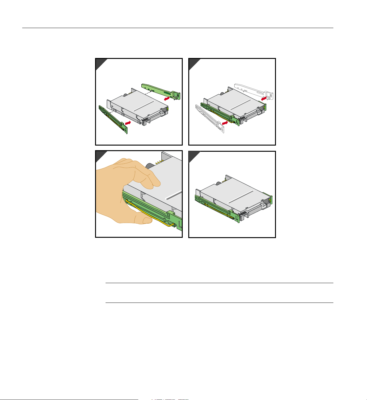
3. The drive rails for the 3.5-inch drives are not interchangeable. They have ‘R’ or ‘L’
markings that indicate which side they have to be mounted on. Before mounting the
rails to the drive, check to be sure the rail marked ‘L’ is on the left side of the drive
and the rail marked ‘R’ is on the right side of the drive, as shown in Figure 2-13.
4. To mount a drive rail to the drive, place one end of the drive rail wire clip into its
drive screw hole. Gently push on the middle of the drive rail until the other end of
the wire clip snaps into its screw hole. Figure 2-13 illustrates the procedure.
5. A 5.25-inch to 3.5-inch drive bay conversion bracket is included in your system. This
bracket can be used in any available 5.25-inch drive bay.
007-4279-001 31
Page 48
2: Installation of Customer Replaceable Components
1
3
2
4
Figure 2-13 Mounting Drive Rails to 3.5-inch drives
6. To mount a 3.5-inch drive in the front-access drive cage, place the drive in the
selected drive bay and slide the drive into the bay until the rails snap into place.
Note: For a drive to be correctly mounted in the front-access drive cage, it must be
installed right side up.
7. Connect cables to the drive.
8. Replace the bezel and the side panel as described in “Post-installation Instructions”
on page 64.
32 007-4279-001
Page 49

Removing and Installing a 3.5-inch Drive in the Internal Drive Cage
The following instructions describe how to remove 3.5-inch drives from the internal
drive cage:
1. Remove the side panel as described in “Pre-installation Instructions” on page 16.
2. Disconnect all cables from the drive to be removed.
3. To remove the drive from a drive bay, press the drive rail plastic release tabs on both
sides of the drive and pull the drive out of the chassis. If the drive is hard to pull
out, you can facilitate the removal by gently pushing the drive from behind.
4. To remove a driverail from the drive, pull therail away from the drive bylifting one
end of the rail.
The following instructions describe how to install 3.5-inch drives in the internal drive
cage:
Note: Only low-profile (i.e., one-inch) drives can be mounted in the internal drive cage.
Removing and Installing Drives
1. All drives are mounted on snap-on drive rails. The Silicon Graphics 550 Visual
Workstation comes with two sets of spare 3.5-inch drive rails. One set of spare
3.5-inch drive rails is located inside the chassis on the side of the 5.25-inch drive
bays. The other set is located inside a plastic bag attached to the side panel.
2. There are two different sets of drive rails for 3.5-inch drives. The difference between
the two sets is the distance between the wire clips. To choose which drive rail fits
your drive, place the drive rail wire clips next to the drive screw holes and verify
that the distance between the wire clips is the same as the distance between the two
screw holes. If the distance is the same, the drive rail is the correct one.
3. The drive rails for the 3.5-inch drives are not interchangeable. They have ‘R’ or ‘L’
markings that indicate which side they have to be mounted on. Before mounting the
rails to the drive, check to be sure the rail marked ‘L’ is on the left side of the drive
and the rail marked ‘R’ is on the right side of the drive, as shown in Figure 2-13.
4. To mount a drive rail to the drive, place one end of the drive rail wire clip into its
drive screw hole. Gently push on the middle of the drive rail until the other end of
the wire clip snaps into its screw hole. Make sure that the connectors face out.
Figure 2-13 illustrates the procedure.
007-4279-001 33
Page 50

2: Installation of Customer Replaceable Components
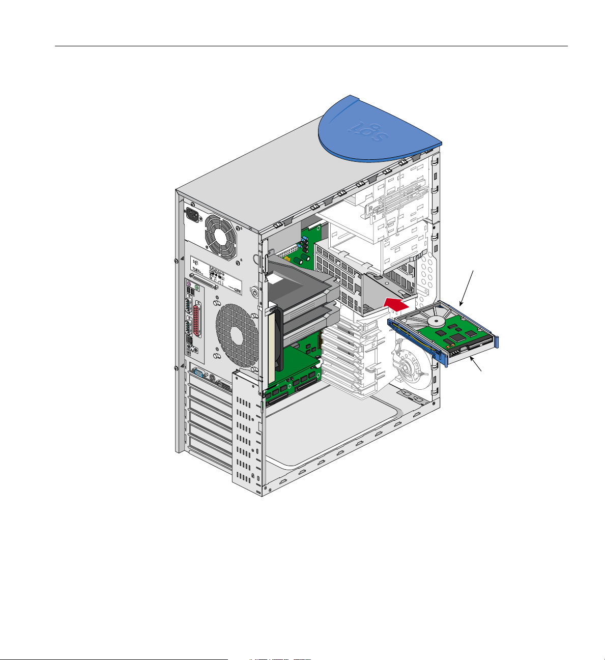
5. To mount a 3.5-inch drive in the internal drive cage, place the drive upside down in
the selected drive bay and slide the drive into the bay until the rails snap into place.
Figure 2-14 shows how to install the drive correctly.
Caution: For a drive to be correctly mounted in the internal drive cage, it must be
installed upside down.
34 007-4279-001
Page 51
Removing and Installing Drives
NOTE
Internal 3.5"
drives install
upside down
1
2
2
1
Connectors
face out
Figure 2-14 Mounting Drives in the Internal Drive Cage
6. Connect cables to the drive.
7. Replace the side panel as described in “Post-installation Instructions” on page 64.
007-4279-001 35
Page 52

2: Installation of Customer Replaceable Components
Replacing the Power Supply
Follow the instructions in this section to remove and replace the power supply.
Warning: Do not open the power supply. Even when unplugged, it may contain
dangerous voltages. There are no user-serviceable parts inside.
1. Unplug the AC power cable from the wall socket and from the power supply.
2. See “Pre-installation Instructions” on page 16 to remove the side panel.
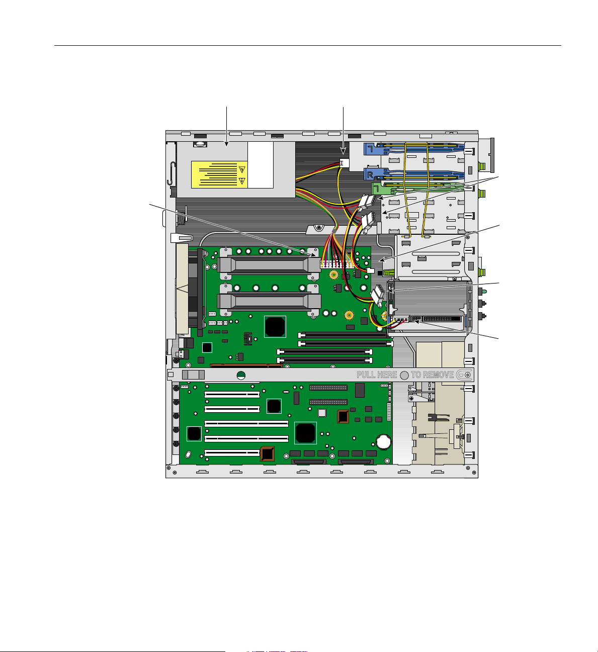
3. Disconnect all the power supply cables from the system board, the 3.5-inch drives
and the 5.25-inch drives. See Figure 2-15 on page 37 for the location of the cable
connections.
4. In order to gain easier access to the power supply, place the system on its right side
on a padded surface so as not to scratch the system.
5. Remove the three power supply screws located on the rear panel. Figure 1-2 on
page 4 shows the location of the screws.
6. Pull the power supply out of the system, avoiding any physical contact between the
power supply and any system component.
7. To install the power supply, continue to rest the system on its right side.
8. Carefully place the power supply into its housing, and push it into place.
9. Replace the three rear screws shown in Figure 1-2 on page 4.
10. Connect the power supply cables to the system board, the hard drive(s), the
CD-ROM drive, and to the floppy disk drive. Refer to Figure 2-15 for the location of
the power supply cable connections.
36 007-4279-001
Page 53
System
board power
Replacing the Power Supply
CD-ROM powerPower supply
Power for
additional
5.25" drives
Floppy
disk drive
power
Additional 3.5"
disk drive
power
System disk
power
Figure 2-15 Connecting Power Supply Cables
11. Replace the side panel as shown in “Post-installation Instructions” on page 64.
12. Reconnect the AC cable to the power supply and to the wall socket.
007-4279-001 37
Page 54

2: Installation of Customer Replaceable Components
Replacing Fans
This section covers the removal and installation of the rear and front system fans.
Replacing the Rear System Fan
Follow the instructions in this section to remove and replace the rear system fan:
1. Remove the side panel as shown in “Pre-installation Instructions” on page 16.
2. Rest the system on its right side on a padded surface so as not to scratch the system.
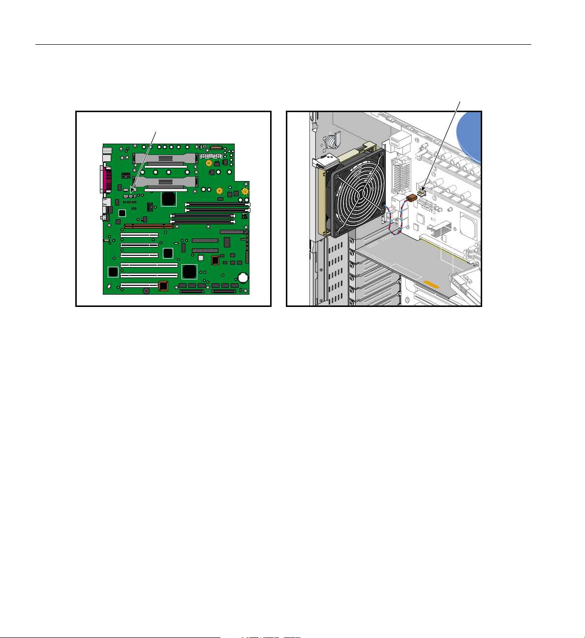
3. Disconnect the fan cable from the system board. See Figure 2-17 on page 40 for the
location of the fan cable connection.
4. Remove the system board as described in “Replacing the System Board” on page 51.
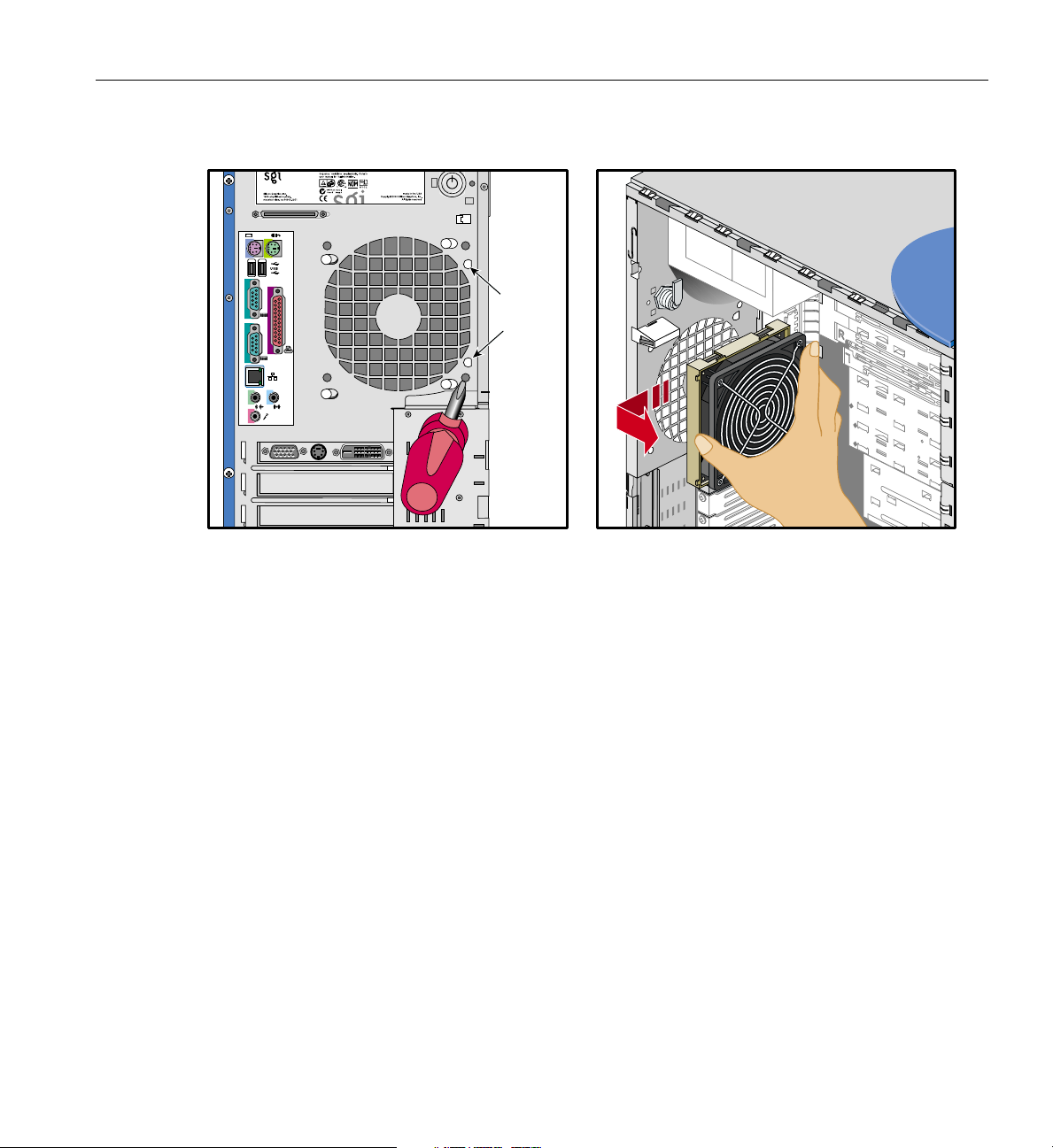
5. Locate the two fan release buttons on the back side of the rear panel, as shown in
Figure 2-16.
6. Using a pointed tool (such as a Phillips-head screwdriver), push on one of the
release buttons while at the same time pulling the fan upward until the release
button comes out of its notch. Keep upward pressure on the fan while pushing on
the second release button until the fan is released from the chassis. Figure 2-16
illustrates the procedure.
38 007-4279-001
Page 55
Replacing Fans
1
2
2
1
Release
buttons
Figure 2-16 Disengaging Release Buttons and Removing Rear Fan
7. Carefully remove the fan from the system without touching any system component.
8. To install the rear fan, keep the system resting on its right side.
9. Insert the fan’s four retaining pins into their respective holes. Make sure that the fan
is positioned so as to have the two release buttons on the upper side of the fan.
10. Push the fan down until the two release buttons click into place.
11. Connect the fan cable. For the location of the rear fan cable connection, see
Figure 2-17.
007-4279-001 39
Page 56
2: Installation of Customer Replaceable Components
Rear fan connection
Rear fan connection
Figure 2-17 Connecting Rear Fan Cable
Replacing the Internal Drive Cage
The following instructions describe how to remove and replace the internal drive cage
from the chassis.
1. Remove the side panel as described in “Pre-installation Instructions” on page 16.
2. Remove the beam as described in “Removing the Beam” on page 18.
3. Remove all drives as described in “Removing and Installing a 3.5-inch Drive in the
Internal Drive Cage” on page 33.
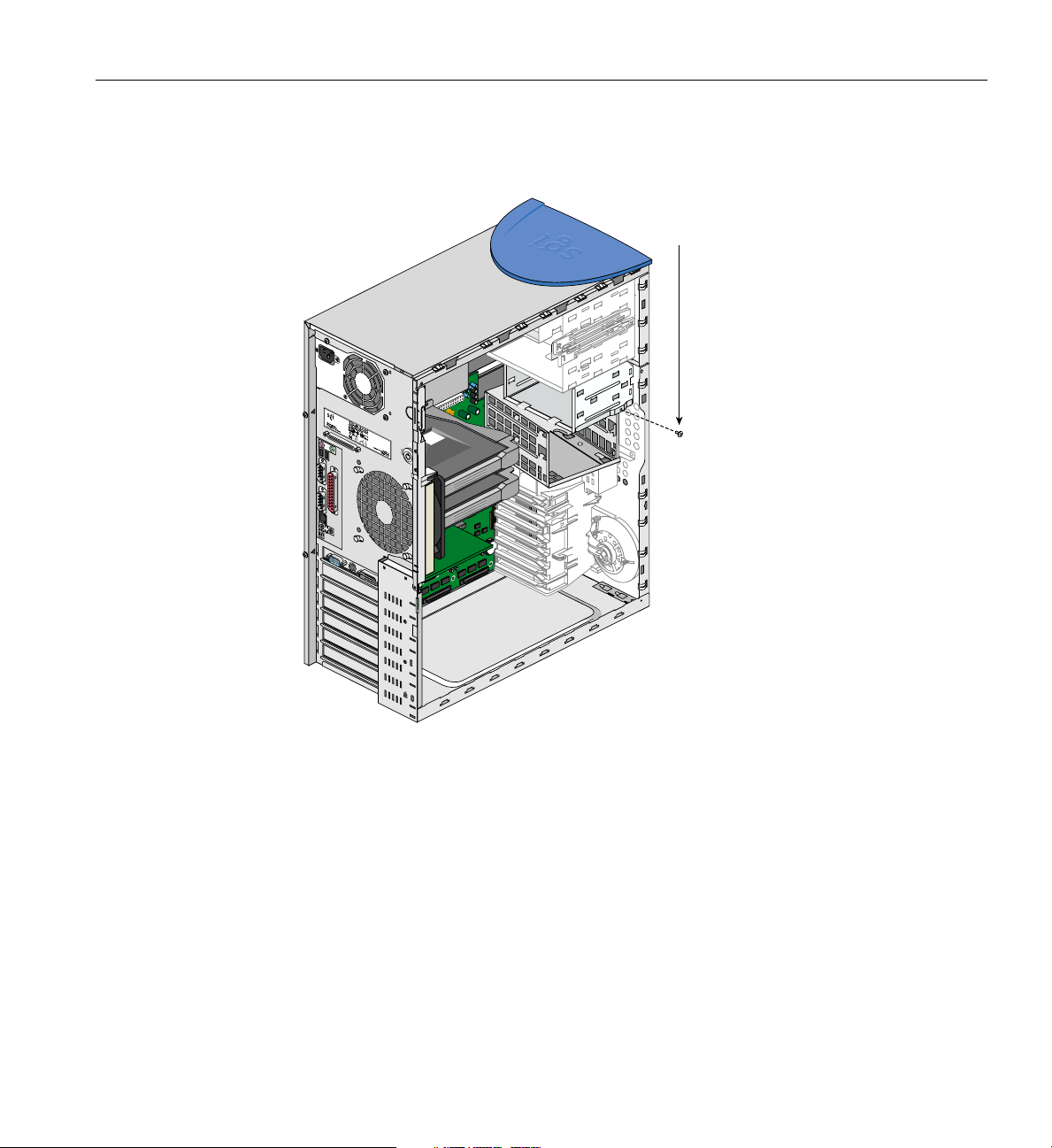
4. Remove the internal cage screw located above the internal drive cage. Figure 2-18
shows the location of the screw.
40 007-4279-001
Page 57
Internal cage screw
Replacing Fans
1
2
2
1
1
2
2
1
Figure 2-18 Location of Internal Cage Screw
5. Remove the two drive sled screws located on the front of the chassis. Figure 1-5 on
page 8 shows the location of these screws.
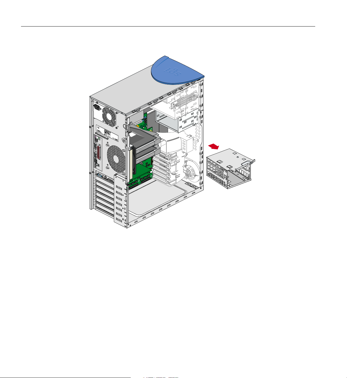
6. After all the screws are removed, the internal drive bracket can be easily removed
by gently pulling the bracket forward.Figure 2-19 shows the bracket being removed
from the system.
007-4279-001 41
Page 58
2: Installation of Customer Replaceable Components
1
2
2
1
Figure 2-19 Removing the Drive Cage
Replacing the Front System Fan
Follow these instructions to remove the front system fan:
1. Remove the side panel and the bezel as shown in “Pre-installation Instructions” on
page 16.
2. Remove the beam as described in “Removing the Beam” on page 18.
3. Disconnect the front fan cable from the system board.
42 007-4279-001
Page 59
Replacing Fans
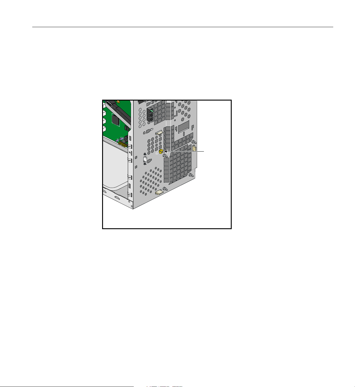
4. Remove the front fan screw located on the front panel. Figure 2-20 shows the
location of the screw.
5. Release the three retaining clips shown in Figure 2-21 by pushing on one clip at a
time while holding the fan plastic frame inside the chassis.
Front fan
screw
Figure 2-20 Removing Front Fan Screw and Releasing Clips
6. Once the three clips are released, the fan plastic frame can be removed from the
system.
7. The fan is held in its plastic frame by four fan retaining clips. To remove the fan
from its plastic frame, place the frame on a flat surface, with the frame facing down,
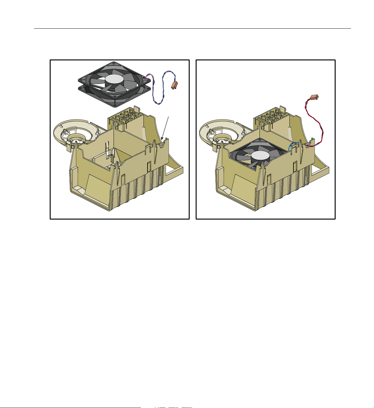
as shown in Figure 2-22.
8. Using a flat screwdriver, gently push on the center of the fan. While pushing on the
fan, release one fan retaining clip at a time by pulling it away from the fan. The
procedure is illustrated in Figure 2-22.
9. Once all four clips have been released, the fan can be removed from the plastic
frame.
007-4279-001 43
Page 60
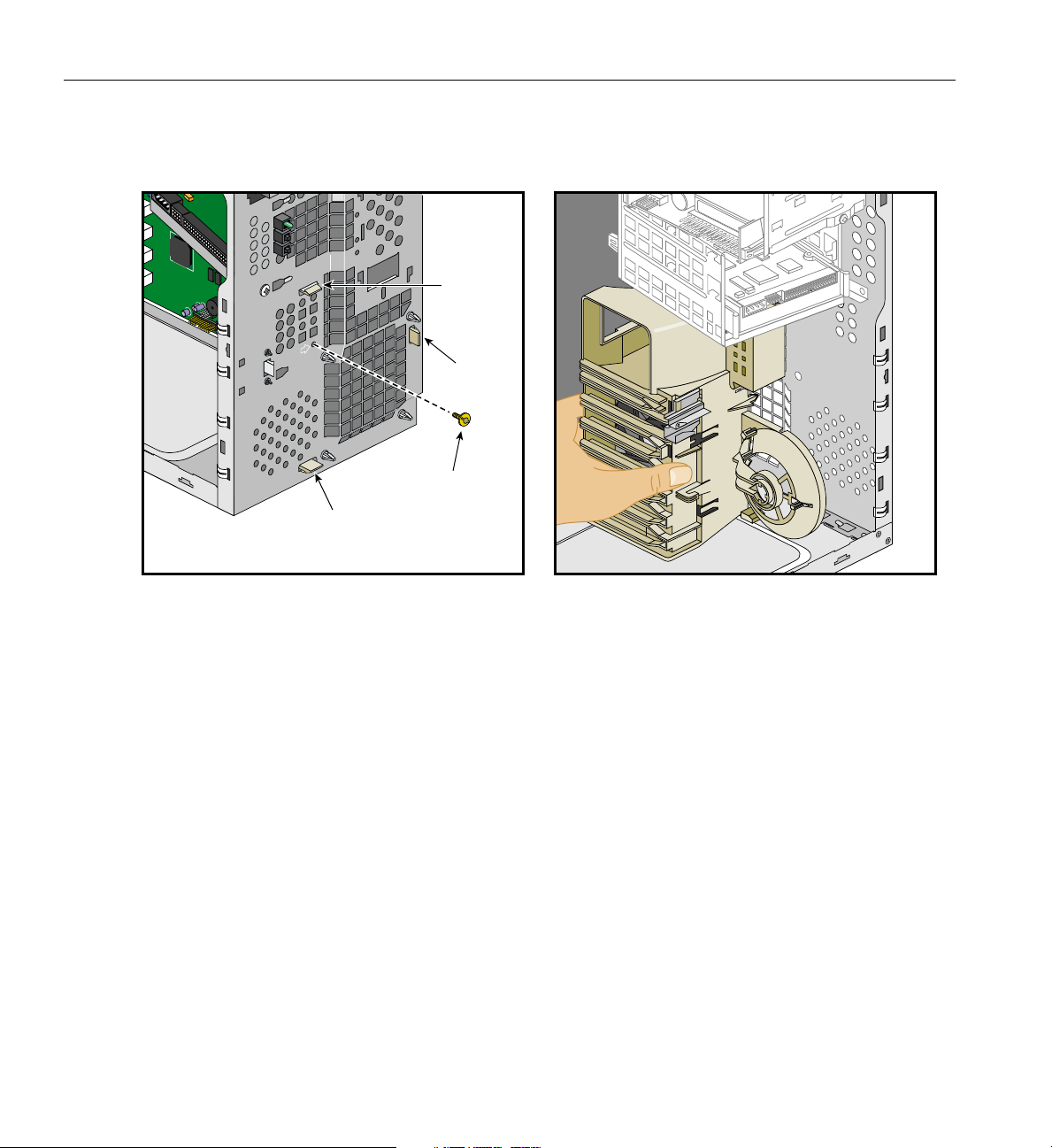
2: Installation of Customer Replaceable Components
Front fan screw
Clip
Clip
Clip
Figure 2-21 Removing Fan from Plastic Frame
Follow these instructions to install the front system fan:
1. To install the front fan, place the plastic frame on a flat surface with its retaining
clips facing up.
2. Insert the fan in its housing. Make sure that the fan cable comes out next to the slot
in the plastic frame, as shown in Figure 2-22.
3. Insert the fan cable into the slot.
4. Pass the cable connector and pull the cable through the hole located next to the cable
slot, as shown in Figure 2-22.
44 007-4279-001
Page 61
Cable hole
Replacing Fans
Figure 2-22 Installing Fan into Plastic Frame
5. Place the fan plastic frame in the chassis and insert the frame guiding pins into their
corresponding holes on the front panel. Push the fan frame until its retaining clips
snap into place.
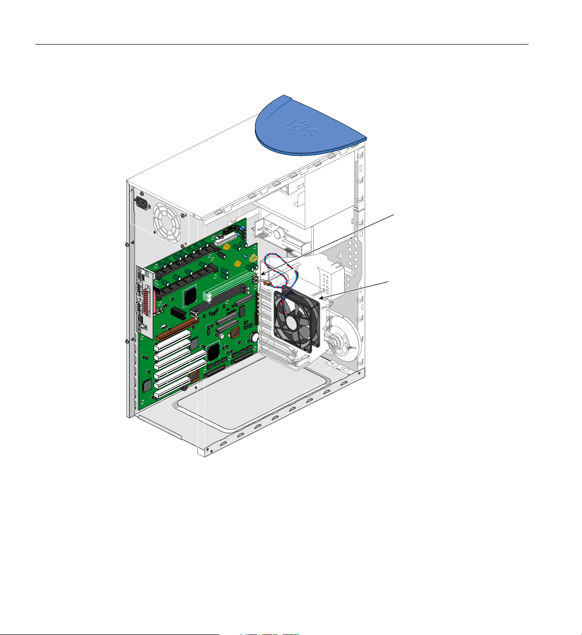
6. Connect the front fan cable. For the location of the front fan cable connection, refer
to Figure 2-23.
007-4279-001 45
Page 62
2: Installation of Customer Replaceable Components
AUDIO OUT
IDE INTERFACE
DC INPUT
FG
Fan power
connection
Front fan
Figure 2-23 Connecting Front Fan Cable
46 007-4279-001
Page 63

Replacing Expansion Cards
This section describes how to remove and install PCI (Peripheral Component
Interconnect) andAGP (Accelerated Graphics Port) cards.Refer to Figure 3-1on page 72
for the location of the expansion card slots.
Follow electrostatic discharge (ESD) precautions. Electronic equipment can be
irreparably damaged by ESD. Always follow these preventative measures when
handling a system component:
• Remove a component from its antistatic bag only when you are ready to install it.
• If you have to handle a component before installation, do not place it on surfaces
that produce ESD (carpeting, for example), or near devices that create static
electricity.
• Attach a static wrist strap to a grounded connection on your system when installing
or removing a component.
The following instructions describe how to remove expansion cards:
1. Remove the side panel as described in “Pre-installation Instructions” on page 16.
Replacing Expansion Cards
2. Remove the beam as described in “Removing the Beam” on page 18.
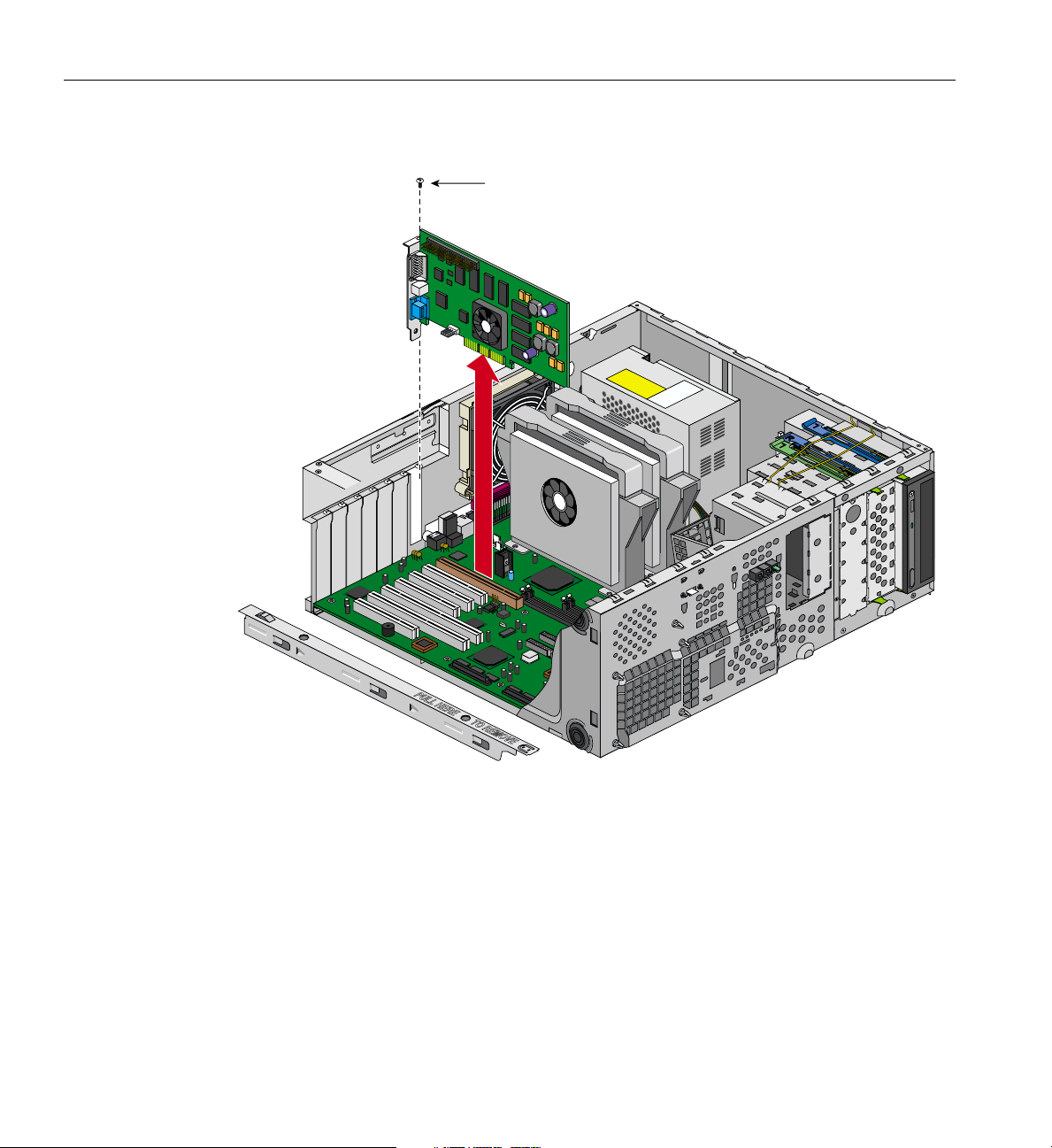
3. Remove the retaining screw for that expansion card, as shown in Figure 2-24.
4. Gently pull the card straight up out of the slot (away from the system board).
007-4279-001 47
Page 64
2: Installation of Customer Replaceable Components
Retaining screw
Figure 2-24 Removing Expansion Card
5. If no other card will be installed in the empty slot, a filler plate needs to be installed
in the expansion slot opening. Follow these instructions to install a filler plate in an
expansion slot opening:
• Place the filler plate on the slot opening
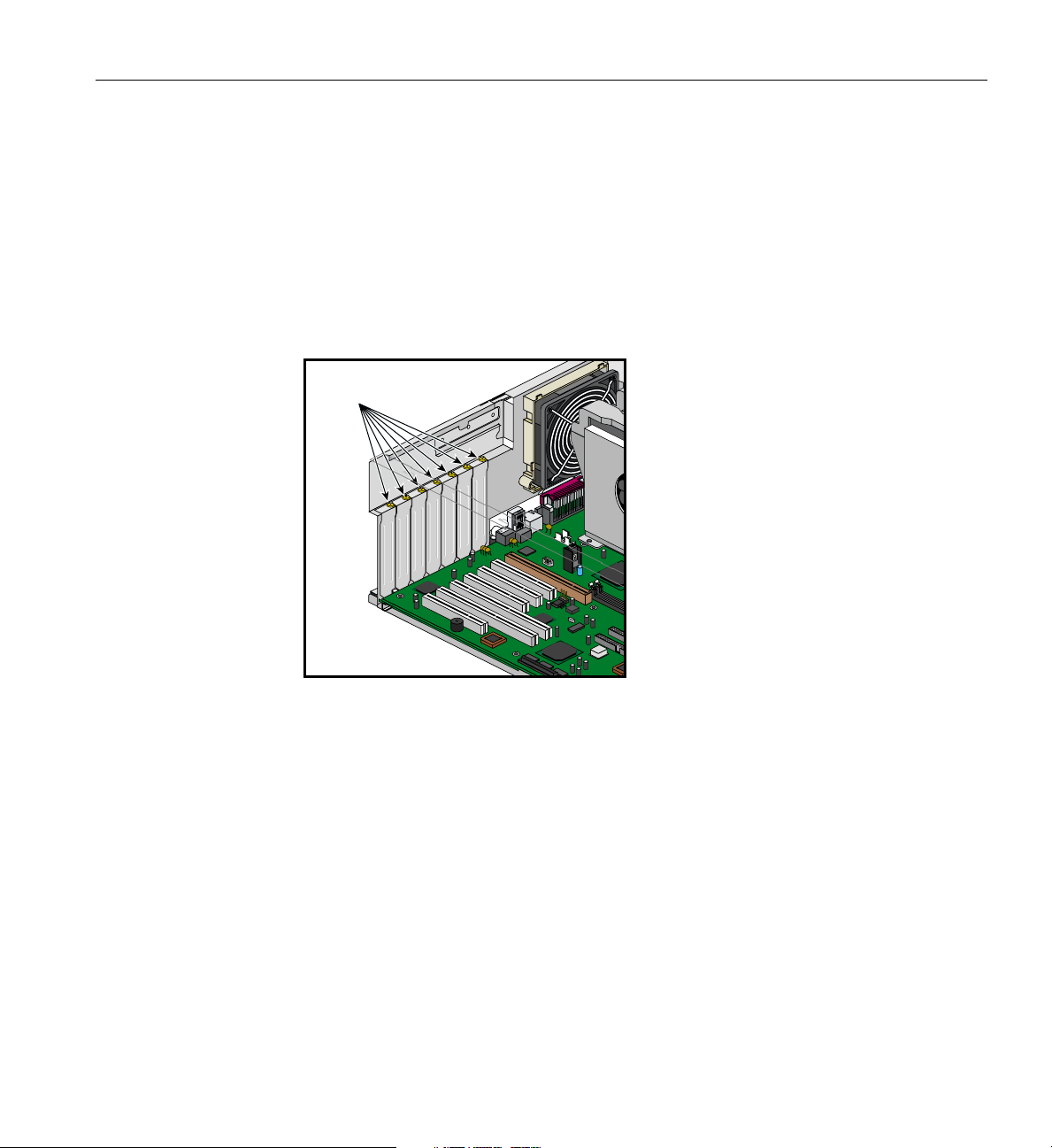
• Tighten the retaining screw shown in Figure 2-25.
The following instructions describe how to install expansion cards:
48 007-4279-001
Page 65
Replacing Expansion Cards
1. Remove the side panel as described in “Pre-installation Instructions” on page 16, if
not already done.
2. If a filler plate covers the slot opening selected for installation, follow these
instructions to remove it:
• Remove the retaining screw shown in Figure 2-25.
• Remove the filler plate from the chassis.
Filler plate
retaining screws
Figure 2-25 Location of the Retaining Screw for the Expansion Slot Filler Plate
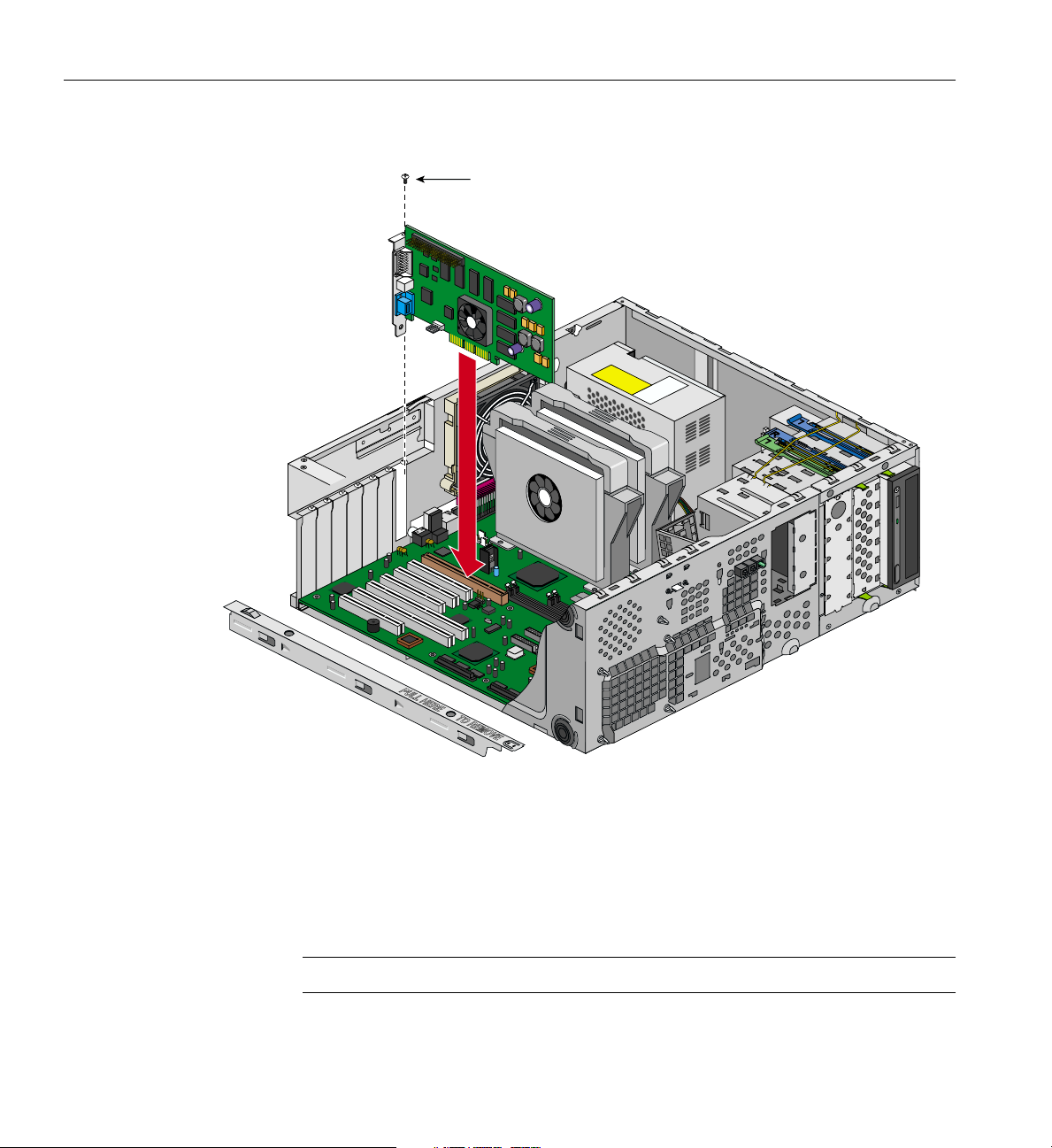
3. Insert the expansion card into its slot by pushing the card into the connector until it
is properly seated. Figure 2-26 illustrates the procedure.
4. Tighten the retaining screw, as shown in Figure 2-26.
007-4279-001 49
Page 66
2: Installation of Customer Replaceable Components
Retaining screw
Figure 2-26 Installing Expansion Card
5. Replace the beam as described in “Replacing the Beam” on page 21.
6. Replace the side panel as shown in “Post-installation Instructions” on page 64.
7. When the system is turned on, the BIOS automatically detects and assigns resources
to the new device.
Note: The BIOS detects and configures only Plug and Play expansion cards.
50 007-4279-001
Page 67

Replacing the System Board
This section describes how to remove and replace the Silicon Graphics 550 Visual
Workstation system board.
Follow electrostatic discharge (ESD) precautions. Electronic equipment can be
irreparably damaged by ESD. Always follow these preventative measures when
handling a system component:
• Remove a component from its antistatic bag only when you are ready to install it.
• If you have to handle a component before installation, do not place it on surfaces
that produce ESD (carpeting, for example), or near devices that create static
electricity.
• Attach a static wrist strap to a grounded connection on your system when installing
or removing a component.
The following instructions describe how to remove the Silicon Graphics 550 Visual
Workstation system board:
Replacing the System Board
Note: Refer to Figure 1-4 on page 6 to review the internal structure of the system.
1. To facilitate the removal of system components, rest the chassis on its right side on a
padded surface so as not to scratch the system.
2. Remove the side panel as described in “Pre-installation Instructions” on page 16.
3. Remove the beam as described in “Removing the Beam” on page 18.
4. Remove all expansion boards. Refer to “Replacing Expansion Cards” on page 47 for
the removal of expansion boards.
5. Disconnect all cables from the system board.
6. Remove the internal drive cage as described in “Replacing the Internal Drive Cage”
on page 40.
7. Remove the front system fan assembly as described in “Replacing the Front System
Fan” on page 42.
8. Remove the two screws at the standoffs at the top of the system board. Refer to
Figure 2-30 on page 55 to see the placement of these screws.
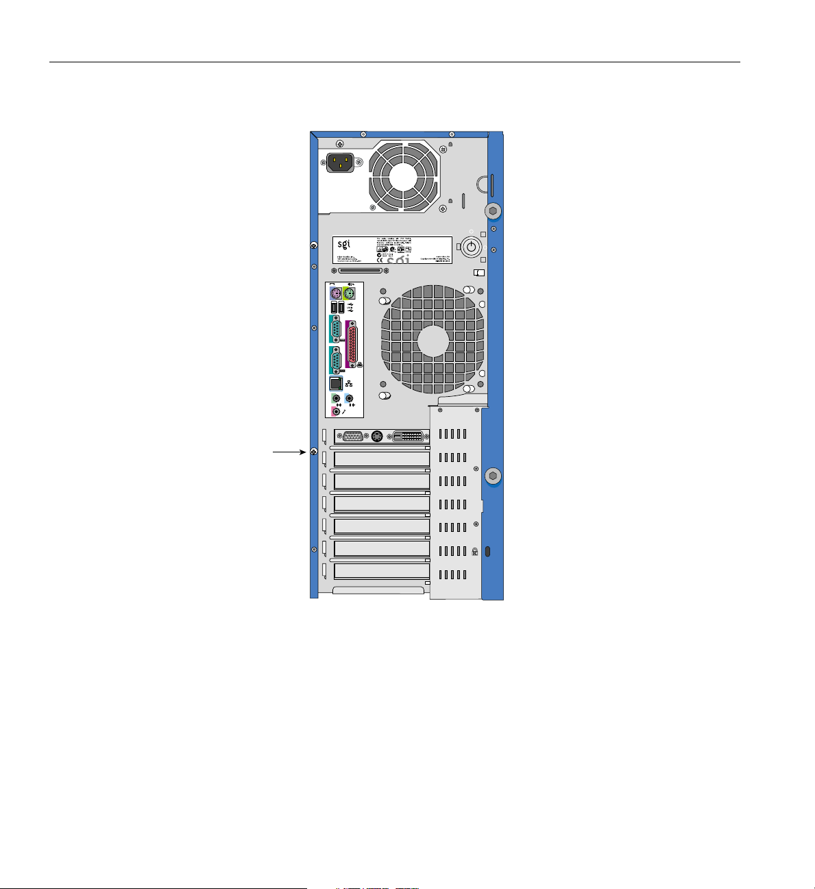
9. Loosen the system board screw. Figure 2-27 shows the location of the screw.
007-4279-001 51
Page 68
2: Installation of Customer Replaceable Components
System
board screw
1
2
2
1
Figure 2-27 Location of System Board Screw
10. Pull the system board away from the I/O gasket and lift the board away from the
chassis.
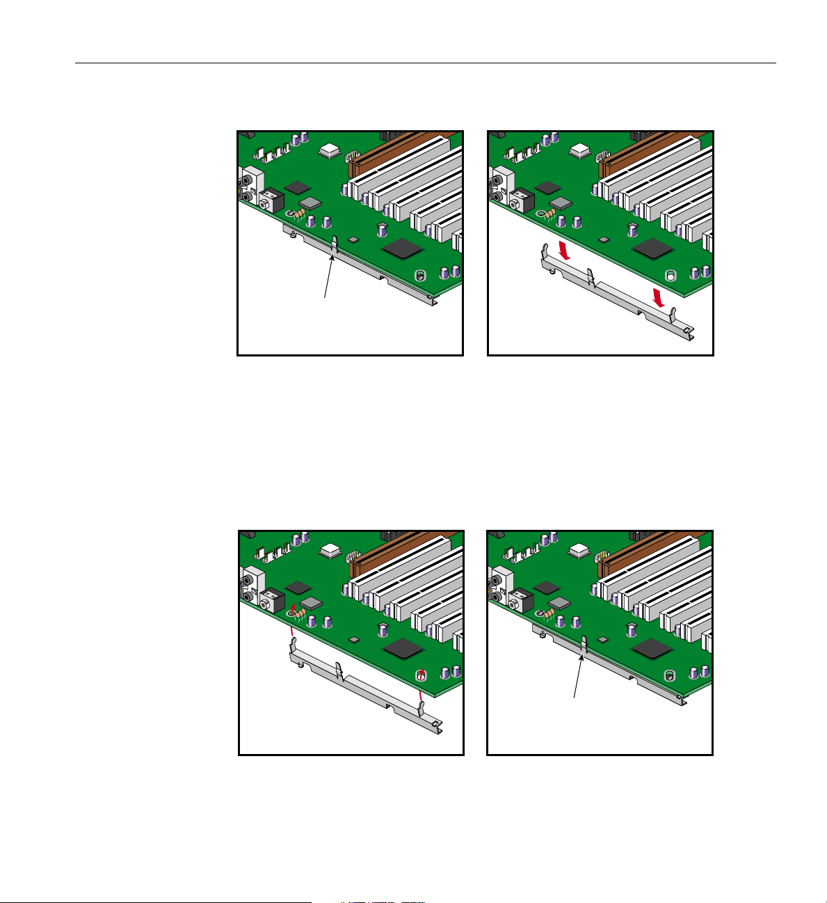
11. To detach the retaining bracket from the system board, unsnap the release clip and
remove the bracket retaining hooks from the system board. Figure 2-28 shows the
procedure.
52 007-4279-001
Page 69
Replacing the System Board
Clip
Figure 2-28 Removing Retaining Bracket from System Board
The following instructions describe how to install the Silicon Graphics 550 Visual
Workstation system board:
1. To mount the retaining bracket onto the system board, place the retaining hooks
into their system board holes and snap the release clip onto the board. Figure 2-29
illustrates the procedure.
Clip
Figure 2-29 Snapping Retaining Bracket onto System Board
007-4279-001 53
Page 70

2: Installation of Customer Replaceable Components
2. The system should still be resting on its right side to facilitate the installation.
3. Place the system board into the chassis so as to align the I/O ports with their
respective holes in the I/O gasket.
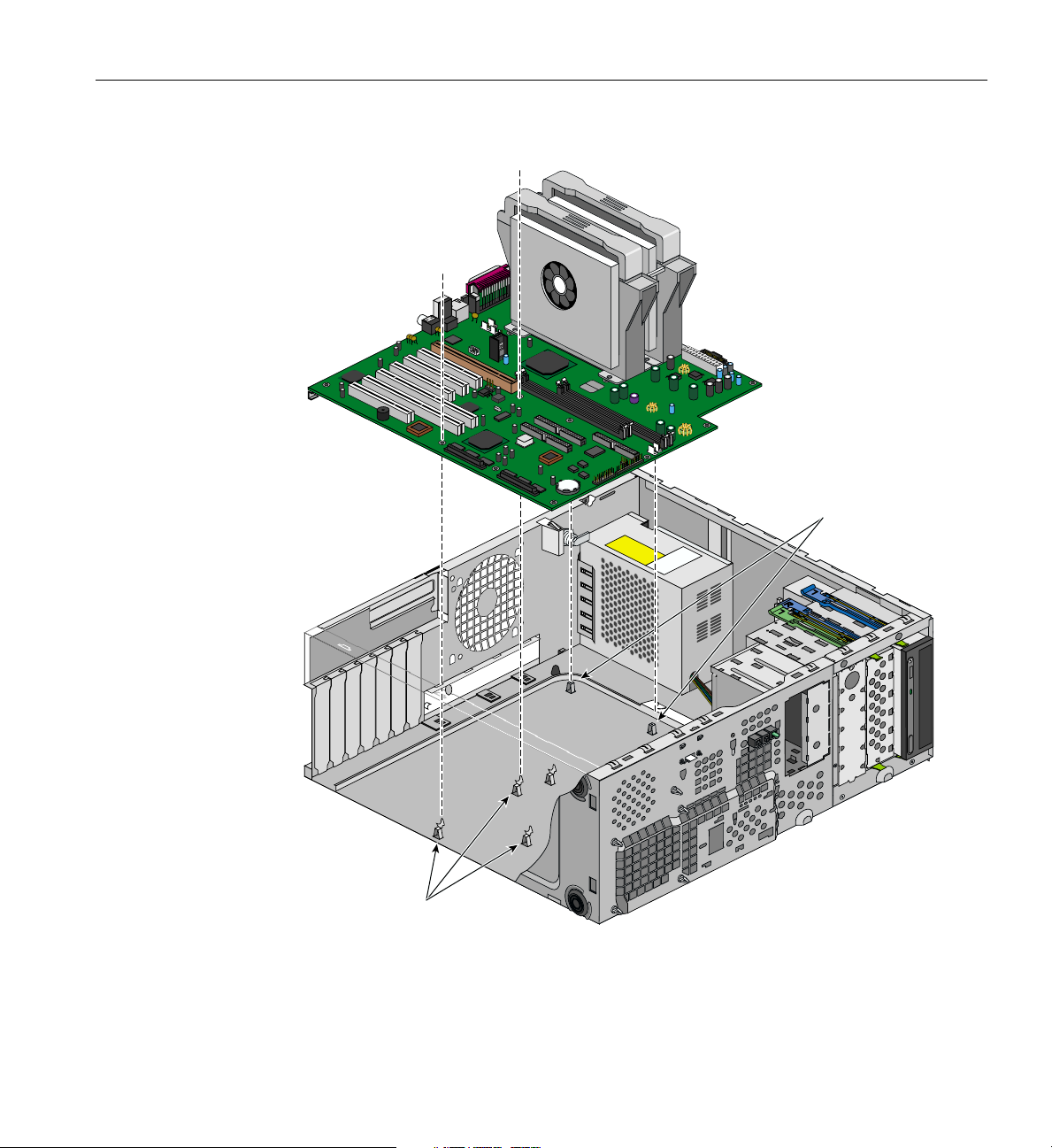
4. Position the system board so as to have the standoff hooks inserted into their
corresponding holes in the system board. See Figure 2-30 for an illustration of the
procedure.
54 007-4279-001
Page 71
Replacing the System Board
Standoffs
Standoff hooks
Figure 2-30 Positioning the System Board on Standoffs and Standoff Hooks
007-4279-001 55
Page 72

2: Installation of Customer Replaceable Components
5. Secure the system board screw onto the retaining bracket. See Figure 2-27 on
page 52 for the location of the system board screw.
6. Replace the front system fan assembly as described in “Replacing the Front System
Fan” on page 42.
7. Replace the internal drive cage as described in “Replacing the Internal Drive Cage”
on page 40.
8. Replace all drives in the internal drive cage as described in “Removing and
Installing a 3.5-inch Drive in the Internal Drive Cage” on page 33.
9. Replace the expansion boards. Refer to “Replacing Expansion Cards” on page 47 for
the installation of expansion boards.
10. Connect all system board cables to their connectors. Refer to Figure 2-31 on page 57
and Figure 3-1 on page 72 for location of system board connectors
56 007-4279-001
Page 73
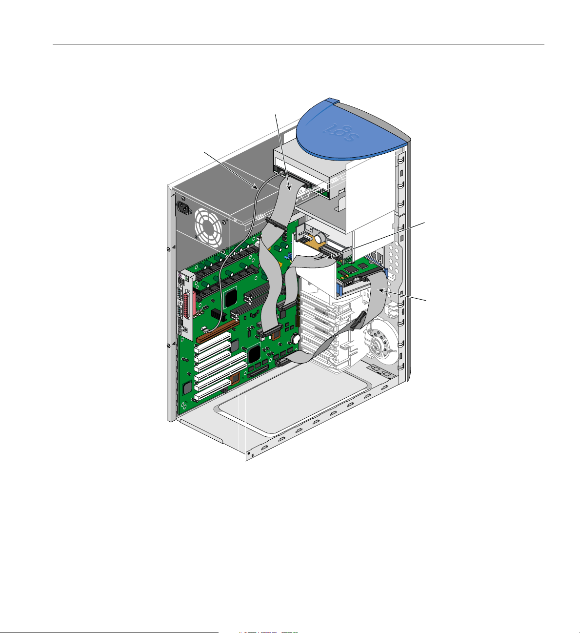
CD-ROM
sound cable
CD-ROM
signal cable
AUDIO OUT
IDE INTERFACE
DC INPUT
Replacing the System Board
FG
Floppy disk
drive cable
System disk
cable
Figure 2-31 Location of System Board Connectors
11. Replace the beam as described in “Replacing the Beam” on page 21.
12. Replace the side panel as shown in “Post-installation Instructions” on page 64.
007-4279-001 57
Page 74
2: Installation of Customer Replaceable Components
Replacing the I/O Panel Gasket
The following instructions describe how to remove the I/O panel gasket. To avoid
scratching and other possible cosmetic problems and to ease in disassembly, the system
should still be resting on its side on a padded surface.
1. Remove the system board as described in “Replacing the System Board” on page 51.
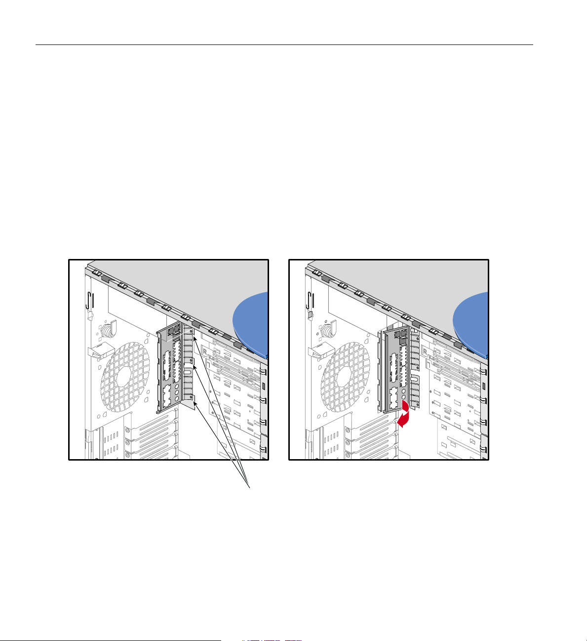
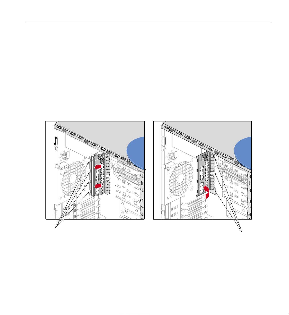
2. Locate the three notched fingers at the bottom of the I/O panel gasket, as shown in
Figure 2-32.
3. To remove the I/O panel gasket, lift one notched finger at a time out of its slot.
4. Once all three notched fingers have been lifted out of their slots, the I/O panel
gasket slides out of its housing and can be removed from the chassis.
Notched fingers
Figure 2-32 Removing I/O Panel Gasket
58 007-4279-001
Page 75
Replacing the I/O Panel Gasket
The following instructions describe how to install the I/O panel gasket:
1. Locate the four retaining slots on the system’s I/O panel opening. See Figure 2-33
for the location of the retaining slots.
2. Insert the I/O gasket’s four indentations into their corresponding retaining slots on
the I/O panel opening. See Figure 2-33 for an illustration of the procedure.
3. In order to secure the I/O gasket on the chassis, each notched finger needs to be
inserted into its slot. To do so, push on the I/O gasket where each notched finger
meets with the I/O gasket until the notched finger snaps into its slot. Repeat the
procedure for the remaining notched fingers.
4. Install the system board as described in “Replacing the System Board” on page 51.
Retaining slots
Notched fingers
Figure 2-33 Installing I/O Panel Gasket
007-4279-001 59
Page 76

2: Installation of Customer Replaceable Components
Securing the System
The Silicon Graphics 550 Visual Workstation’s side panel can be locked into place on the
system using a locking loop and a padlock, thus preventing access to the internal
components of the system. The locking loop is stored in a slot on the chassis and needs
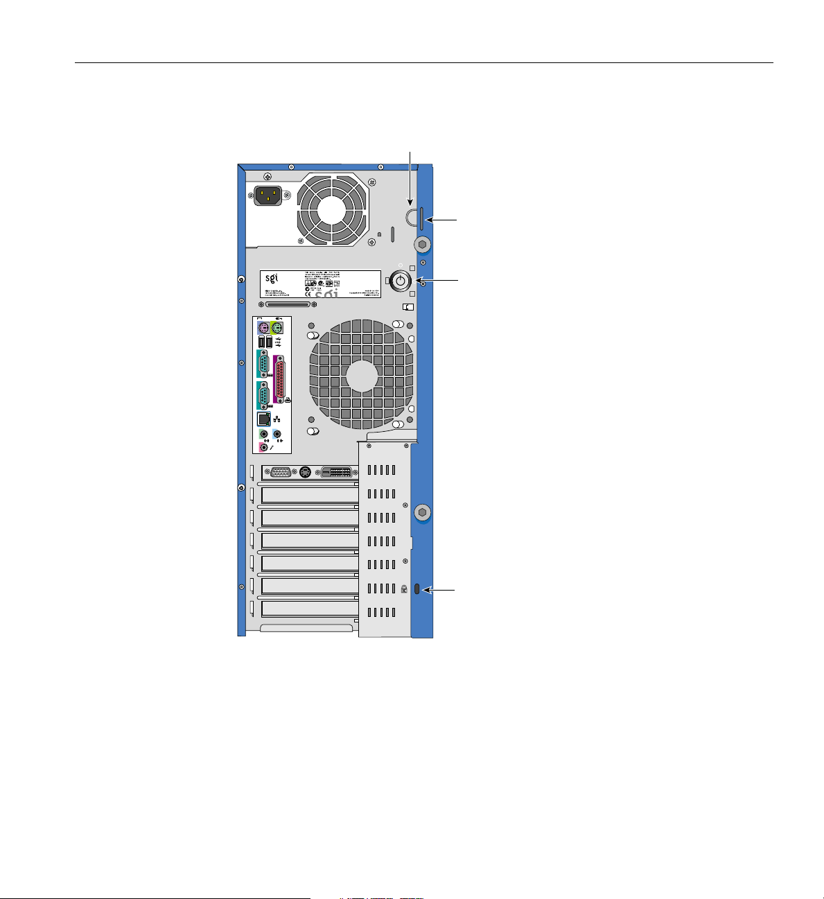
to be moved to another slot to be used. Follow these steps to install the locking loop:
1. Remove the side panel if not already done. For removal of the side panel, refer to
“Pre-installation Instructions” on page 16.
2. Locate the locking loop. See Figure 2-34 for the location of the locking loop.
60 007-4279-001
Page 77
Securing the System
Locking loop
Locking loop slot
Key lock
1
2
2
1
Slot for
Kensington lock
Figure 2-34 Location of Locking Loop
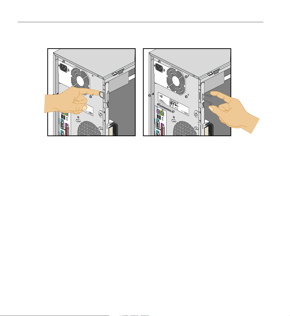
3. Remove the locking loop from its storage slot by pressing the two hooks towards
each other and pushing the loop out of the chassis. Figure 2-35 illustrates the
procedure.
007-4279-001 61
Page 78
2: Installation of Customer Replaceable Components
1
2
2
1
2
2
Figure 2-35 Removing Locking Hook from its Storage Slot
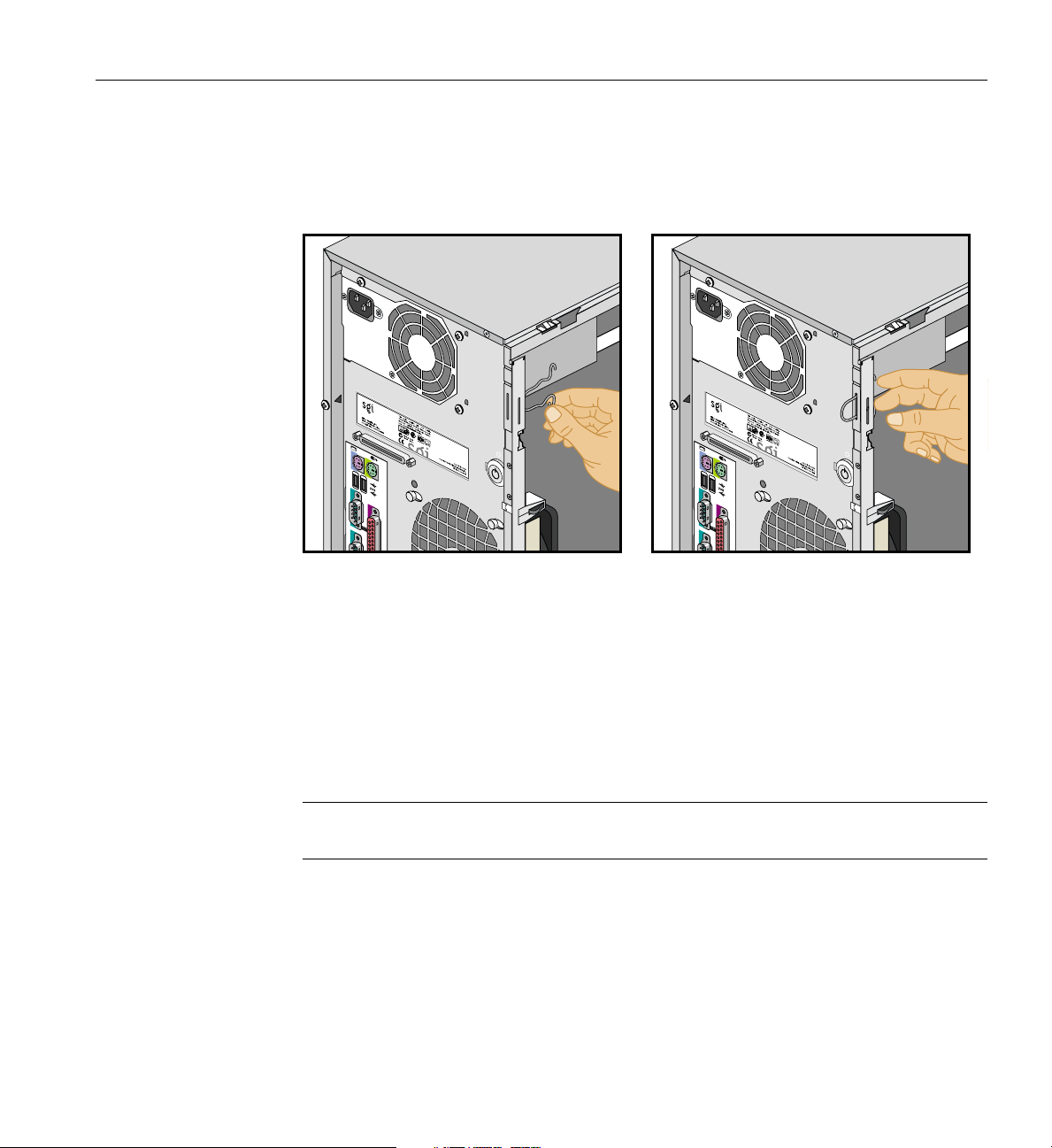
4. Locate the slot facing the rear of the chassis. See Figure 2-34 for the location of the
slot.
62 007-4279-001
Page 79
Securing the System
5. Insert the loop part of the locking loop into the slot inside the chassis and push the
locking loop until it snaps into place. Figure 2-36 illustrates the procedure.
1
2
2
1
2
2
Figure 2-36 Installing Locking Loop in its Functional Slot
6. Replace the side panel as described in “Post-installation Instructions” on page 64.
7. To lock the side panel on the system (see “Post-installation Instructions” on page 64
for side panel installation), insert a padlock into the locking loop.
The system itself can be secured in a particular location by using a Kensington locking
device. See Figure 1-2 on page 4 for the location of the Kensington lock slot.
Note: A Kensington locking device is not included with the Silicon Graphics 550 Visual
Workstation.
007-4279-001 63
Page 80
2: Installation of Customer Replaceable Components
Post-installation Instructions
After completing the installation of customer replaceable components, follow these
instructions to ready the system for operation:
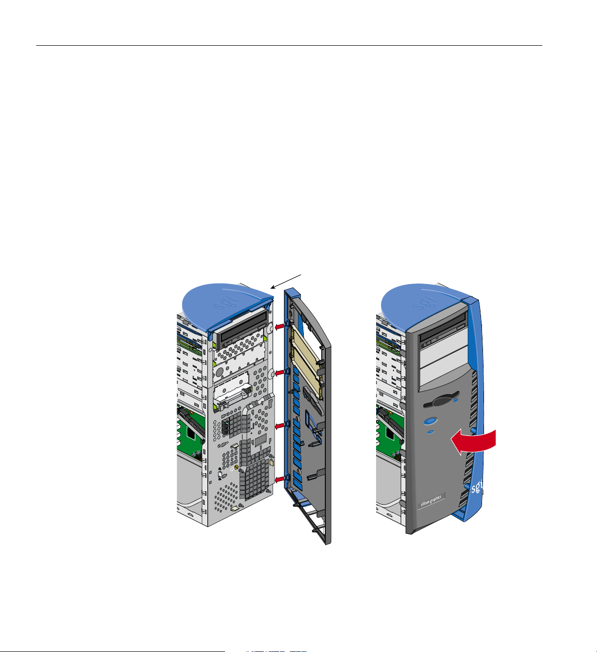
1. If your installation involved the removal of the bezel, follow these steps to replace
the bezel:
• Locate the four tabs on the right side of the bezel, as shown in Figure 2-37.
• Place the right side of the bezel on the chassis so asto insert the four tabs in their
respective slots, as shown in Figure 2-37.
• Push the left side of the bezel towards the chassis until all four tabs on the left
side of the bezel are securely snapped onto the chassis.
Right side
Figure 2-37 Replacing Bezel
64 007-4279-001
Page 81
Post-installation Instructions
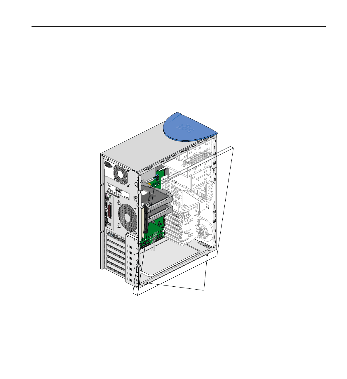
2. Follow these steps to replace the side panel:
• Locate the two tabs on the lower side of the side panel.
• Place the two tabs onto the lower chassis rail.
• Slide the side panel toward the rear of the system, until the rear tab hits the rear
of the chassis and the side panel cannot be moved any farther. Figure 2-38
illustrates the procedure.
1
2
2
1
Side panel tabs
Figure 2-38 Placing Side Panel onto Lower Chassis Rail
• Push the upper side of the side panel toward the chassis.
007-4279-001 65
Page 82
2: Installation of Customer Replaceable Components
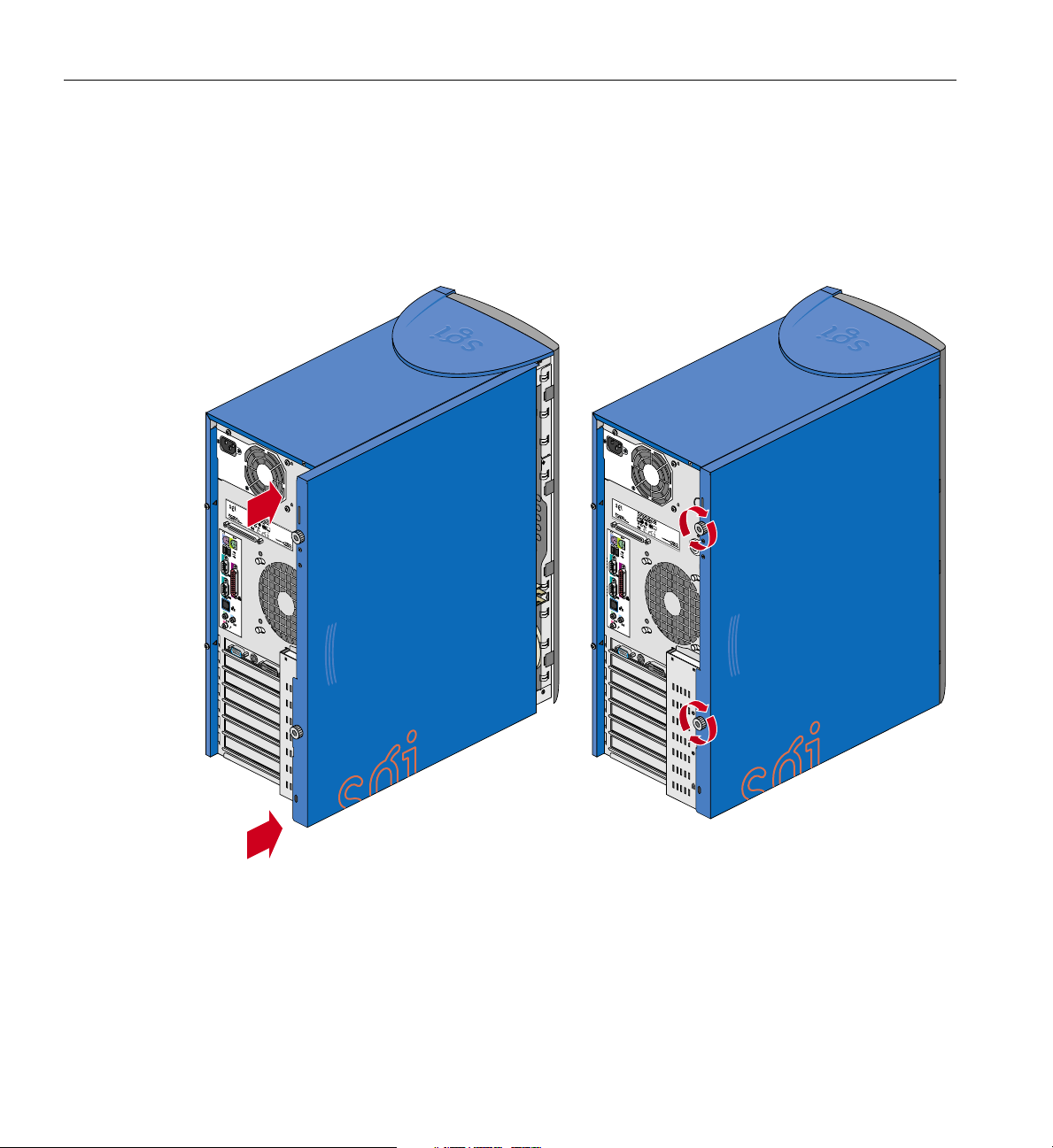
• Gently lift the side panel and push it against the chassis.
• Slide the side panel towards the front of the chassis until it fits into place. The
procedure is illustrated in Figure 2-39.
• Tighten the two thumbscrews on the back of the case.
1
2
2
1
1
2
2
1
Figure 2-39 Sliding Side Panel into Place
3. To connect your system to external devices, refer to “Connecting External Devices”
on page 9.
4. To turn on the system, press the power button on the front panel. See Figure 1-1 on
page 3 for the location of the power button.
66 007-4279-001
Page 83

Chapter 3
3. System Board
The Silicon Graphics 550 Visual Workstation contains an M29A system board. This
chapter describes the M29A system board and all its major components. It contains the
system board layout, jumper settings, cache and memory configurations, and
information on other internal devices.
007-4279-001 67
Page 84

3: System Board
Overview
Processor
The M29A system board is a PCI bus-based, dual-processor system board built on an
extended ATX baseboard. It comes with dual Slot 2 processor sockets using Pentium III
Xeon processors integrated with the Intel i840 chipset. The system board also integrates
the Intel 82559 10/100 Mbps PCI Ethernet chipset that supports WOL (Wake on LAN)
and AOL (Alert on LAN) for better remote site management.
For expandability, the system includes one AGP Pro (Accelerated Graphics Port) slot,
four 32-bit PCI-bus slots, two 64-bit PCI-bus slots, and four RIMM sockets. It also
includes integrated SCSI via an Adaptec 7899 dual channel Ultra160/M controller.
For connectivity, the system board supports two USB (Universal Serial Bus) connectors,
a speaker-out/line-out, audio-in, and microphone-in port, and other standard features
such as two UART NS16C550 serial ports, one enhanced parallel port with Enhanced
Parallel Port (EPP)/Extended Capabilities Port (ECP) support, a diskette drive interface,
and two embedded hard disk interfaces.
The Pentium III Xeon processor implements a Dynamic Execution micro-architecture, a
unique combination of multiple branch prediction, data flow analysis, and speculative
execution. The Pentium III Xeon processor improves upon previous generations of Intel
processors by adding Streaming SIMD (Single Instruction Multiple Data) extensions. The
SIMD extensions significantly accelerate performance of 3D graphics. Besides 3D
graphics improvements, the extensions also include additional integer and cacheability
instructions that improve other aspects of performance.
In addition, the Pentium III Xeon processor uses a variation of the S.E.C (Single Edge
Contact) package technology first introduced on the Pentium II processor. The SEC
packaging technology allows the Pentium III Xeon processor to implement Dual
Independent Bus Architecture and has 256KB of level2 cache. Level 2 cache is integrated
in the processing unit and communication occurs at the full speed of the processor core.
The Pentium III Xeon processor supports both uniprocessor and multiprocessor
implementations with support for two processing units on each local processor bus, or
system bus.
68 007-4279-001
Page 85

Memory
System Chipsets
Intel i840 Chipset
Overview
The four RIMM sockets on the board allow a maximum of 2GB of memory using four
512-MB RDRAM (Rambus DRAM) RIMMs. RDRAM is a new high-performance
memory technology that increases overall system throughput when running
workstation applications.
Intel Scalable Bandwidth Technology provides the Intel 840 chipset with the ability to
meet the needs of high performance multi-processor systems utilizing the Intel Pentium
III Xeon processor. In addition, the 840 chipset provides up to 3.2 GB/s of memory
bandwidth and supports the new high-performance RDRAM memory technology.
The 840 chipset has three core components:
• The 82840 Memory Controller Hub (MCH) differentiates the Intel 840 chipset from
other Intel 800 series chipsets. The MCH provides graphicssupport for AGP 2X/4X,
dual RDRAM memory channels, and multiple PCI segments for high performance
I/O.
• The 82801 I/O Controller Hub (ICH) utilizes Intel Hub Architecture to make a
direct connection to the MCH. The ICH supports 32-bit PCI, IDE controllers and
dual USB ports.
• The 82802 Firmware Hub (FWH) stores system BIOS and video BIOS, as well as an
Intel Random Number Generator (RNG). The Intel RNG provides truly random
numbers to enable stronger encryption, digital signing and security protocols.
In addition to providing high performance, the Intel 840 chipset was designed for
scalability. The 82806 64-bit PCI Controller Hub (P64H) supports 64-bit PCI slots at
speeds of either 33 or 66 MHz. The P64H connects directly to the MCH using Intel Hub
Architecture, providing a dedicated path for high performance I/O.
LAN Subsystem
Intel’s 82559 10/100 Mbps Fast Ethernet controller supports Advanced Configuration
and Power Interface (ACPI) 1.20A based power management, wake on Magic Packet,
wake on interesting packet, advanced System Management Bus (SMB) based
007-4279-001 69
Page 86

3: System Board
Expansion Slots
AGP Pro Bus
PCI Bus
manageability, Wired for Management (WfM) 2.0 compliance, IP checksum assist, PCI
2.2 compliance, and PC 98, PC 99, and Server 99 compliance.
The AGP Pro specifies an extension of the existing AGP bus. It delivers four times the
electrical power of the current AGP specification supported by both 2X and 4X AGP
modes. MCH provides an AGP interface as an independent graphics controller which
makes it ideal for users of simulation, mechanical CAD, financial modeling and digital
content creation applications.
The system board has four PCI buses that support 32-bit/33 MHz PCI devices and two
PCI buses that support 64-bit/66 MHz PCI devices.
Hardware Management Support
The system board supports the power-management function that conforms to the
power-saving standards ofthe U.S. Environmental Protection Agency(EPA) Energy Star
program. It also offers the Plug-and-Play feature. This feature saves the user from
configuration troubles, thus making the system more user-friendly.
Major Components
The system board has the following major components:
• Slot 2 processor socket that supports Pentium III Xeon processors and future
generation Pentium CPUs
• Intel i840 chipset
• Onboard 10/100 Mb/s Intel 82559 LAN chip that supports WOL and AOL
• Four RIMM sockets that accept 64-, 128-, 256, and 512-MB RDRAMs with a
maximum memory capacity of 2GB
70 007-4279-001
Page 87

Major Components
• One AGP Pro slot, four 32-bit PCI bus slots, and two 64-bit PCI bus slots
• Integrated Adaptec 7899 with dual channel Ultra160/M controller
• System clock/calendar with battery backup
• IDE hard disk and diskette drive interfaces
• External ports:
USB connector Serial port 1 and 2
PS/2-compatible keyboard port Speaker-out/Line-out port
PS/2-compatible mouse port Audio-in port
10/100 MBps Ethernet port Microphone-in port
Parallel port
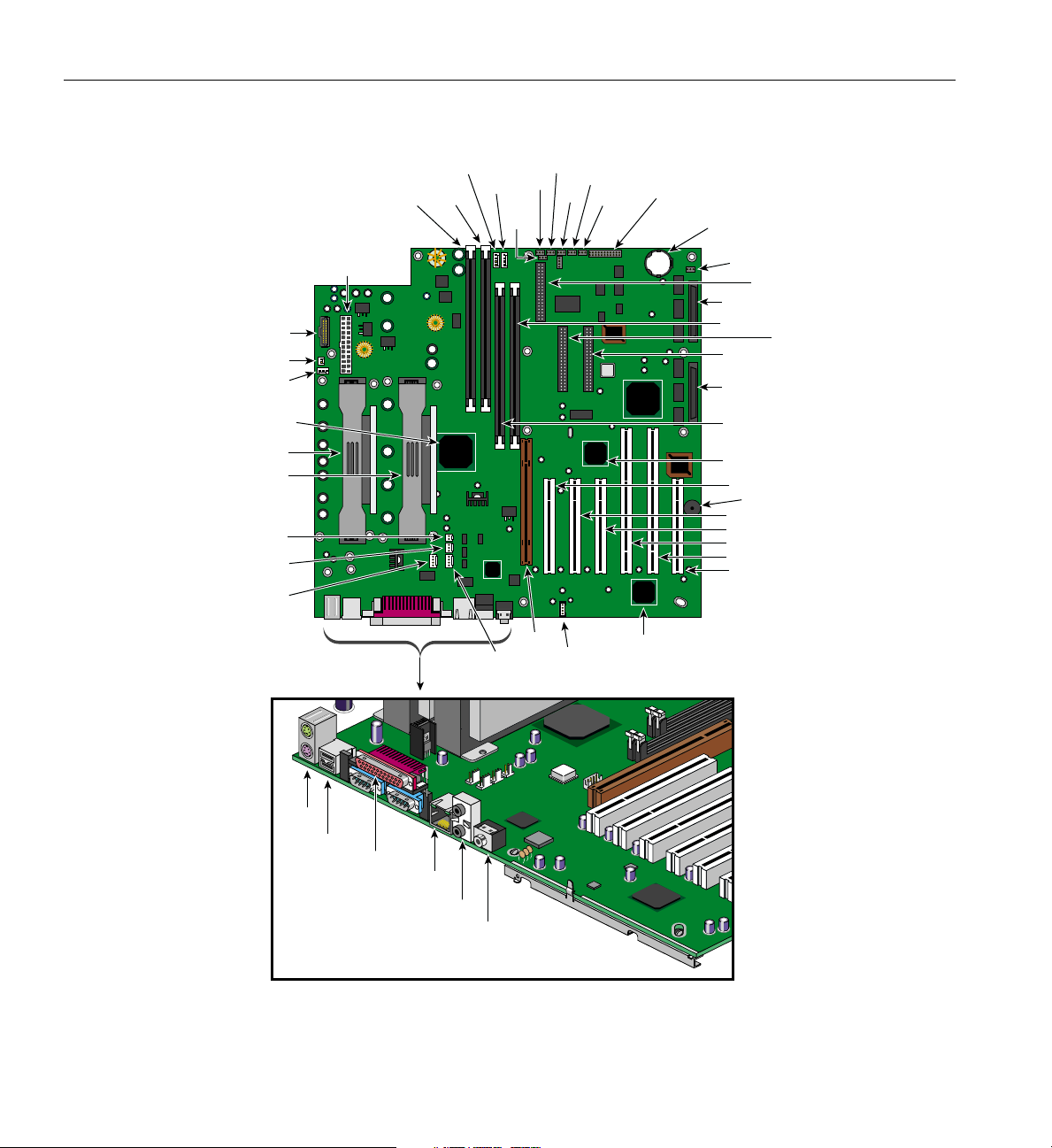
Figure 3-1 shows the layout of the system board.
007-4279-001 71
Page 88
3: System Board
CN3
CN1
CN2
CPU1
CPU2
CN11
CN10
Rear
fan
U9
CN5
RM1
Front fan
RM2
Fan 4
Fan 1
JP1
JP2
A1
JP4
CN14
JP5
JP6
JP7
U64
CN29
BT1
JP8
CN17
CN33
RM4
CN28
CN32
System drive
RM3
U4
PCI 1
BU1
PCI 2
PCI 3
PCI 4
PCI 5
PCI 6
CN23
CN4
CN7
CN8
CN12
CN13
CN15
Figure 3-1 System Board Layout
72 007-4279-001
Page 89

Table 3-1 describes the system board items in Figure 3-1.
Table 3-1 System Board Items
Item Description
A1 AGP slot
BT1 Battery
BU1 Buzzer
CN1 CPU 1 thermal sensor connector
CN2 CPU 1 fan connector
CN3 Power assist
CN4 Upper: PS/2 mouse connector
Lower: PS/2 keyboard connector
CN5 Power connector
CN7 USB connectors
Major Components
CN8 Upper: Parallel port
Lower left: Serial 1 port
Lower right: Serial 2 port
CN10 CPU 2 thermal sensor connector
CN11 CPU 2 fan connector
CN12 LAN jack (RJ45)
CN13 Upper: Line-out port
Lower: Audio-in port
CN14 CD-ROM connector
CN15 Mic-in port
CN17 FDD connector
CN22 Reserved
CN23 IDE2 connector
CN28 IDE1 connector
007-4279-001 73
Page 90

3: System Board
Table 3-1 (continued) System Board Items
Item Description
CN29 Front connector
CN30 Wake on LAN connector
CN32 Ultra 160/m SCSI channel A connector
CN33 Ultra 160/m SCSI channel B connector
CPU1-2 Two CPU Slot-2 slots
Fan1-4 Housing fan connectors
RM1-4 RIMM slots
JP1 Password settings
1-2: Check password
2-3: Bypass password
JP2 BIOS settings
1-2: OEM BIOS
2-3: BIOS
JP4 Flashed BIOS safety boot
1-2: FWH top lock
2-3: FWH top unlock
JP5 System reboot when POST timed out
1-2: Timeout reboot
2-3: Don’t reboot
JP6 Onboard buzzer/external speaker
1-2: Onboard Buzzer
2-3: External speaker
JP7 Force CPU to run at2 x 133 MHz or 2 x 100
MHz
1-2: Set by ICH1111
2-3: CPU strap
JP8 SCSI terminator for Channel A
1-2: SCSI terminator off
2-3: SCSI terminator on
JP8X SCSI terminator for Channel B
74 007-4279-001
Page 91
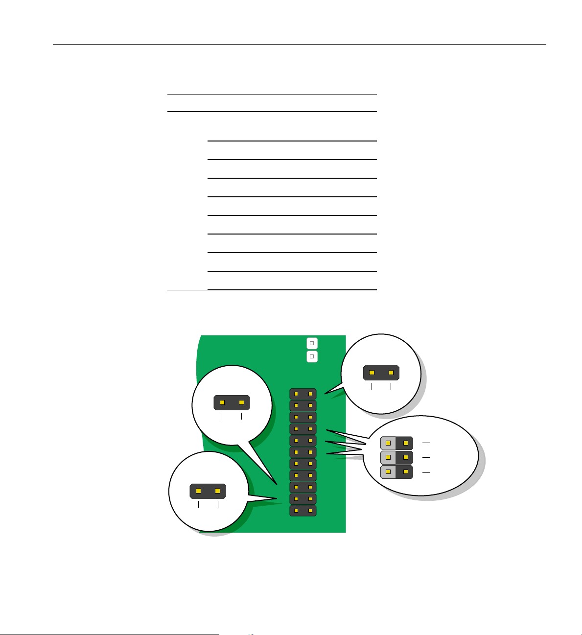
Table 3-1 (continued) System Board Items
Item Description
Major Components
P1,2,3,
32-bit/33-MHz PCI slots
and 6
P4 and 5 64-bit/66-MHz PCI slots
U4 Intel 82801 chipset (ICH)
U9 Intel82840 chipset (MCH)
U16 Intel 82559 LAN chipset
U37 SMC 47B277 super I/O chipset
U48 AD1881 audio chipset
U63 Adaptec AIC-7899 chipset
U64 Intel 82806 chipset (P64H)
Figure 3-2 shows the parts of the front connector (CN29).
Power button
12
Power LED
Reset switch
18 17
Black Blue
Intrusion switch
Black Red
CN29
11
13
15
17
19
21
1
3
5
7
9
Black Red
2
4
6
8
10
12
14
16
1920
18
20
22
11
White
7
9
Orange
Green
Figure 3-2 Front Connector (CN29)
007-4279-001 75
Page 92

3: System Board
System Component Installation
The following sections show you how to install system components like the CPU,
memory modules, and expansion cards.
ESD Precautions
Always observe the following electrostatic discharge (ESD) precautions before installing
a system component:
1. Do not remove a component from its antistatic packaging until you are ready to
install it.
2. Wear a wrist grounding strap before handling electronic components. Wrist
grounding straps are available at most electronic component stores.
Installing and Removing the Processor
Note: Observe the ESD precautions when installing or removing a system component.
See “ESD Precautions” on page 76.
Each PentiumIII Xeon comes in a drop-in SC330 (330-pin slot connector) SECC (Single
Edge Contact Connector) package.
The system board supports dual Pentium III Xeon processors running at 733 MHz, 800
MHz, 866 MHz, and 933 MHz with on-die 256 KB L2 cache on a 133-MHz system bus
Installing the Retention Mechanism
The retention mechanism needs to be installed to support and hold the processor in
place. To install the retention mechanism, complete the following steps:
76 007-4279-001
Page 93
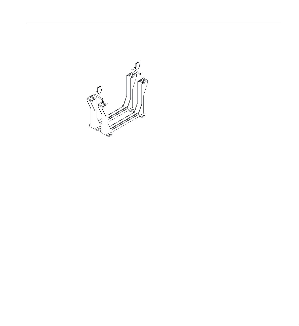
System Component Installation
1. Attach both of the retention mechanisms with joint bars. Snap in the joint bars on
both sides of the retention mechanisms, as shown in Figure 3-3.
Figure 3-3 Joint Bars
2. Align and insert the metal plate beneath the system board along the Slot 2 retention
holes, as shown in Figure 3-4.
007-4279-001 77
Page 94
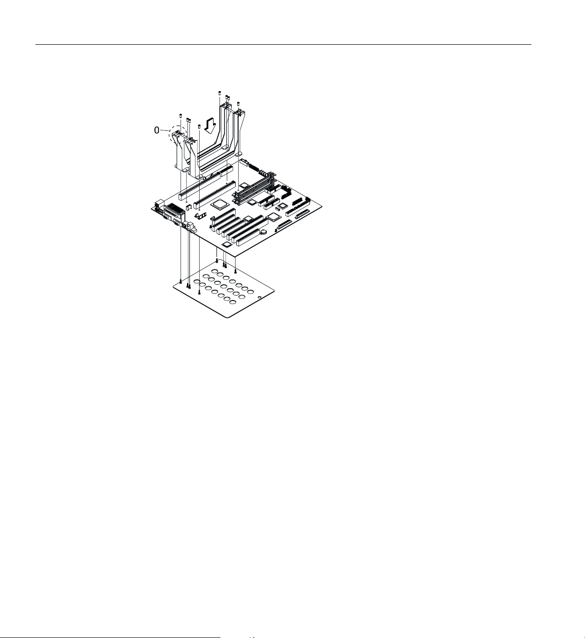
3: System Board
Figure 3-4 Metal Plate
3. Insert both of the retention mechanisms into the Slot 2 sockets. Make sure that the
shafts of the retention mechanism with O signs are facing the external ports of the
system board.
4. Secure the retention mechanisms with six screw nuts, three for each retention
mechanism.
Installing the Processor
Complete the following steps to install a processor:
78 007-4279-001
Page 95
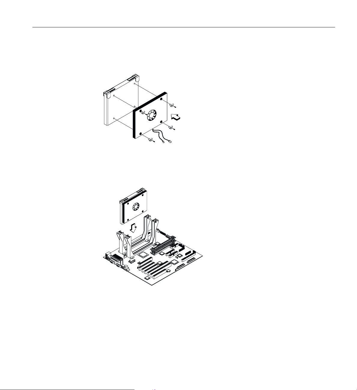
System Component Installation
1. Attach the fan/heatsink module to the Pentium III Xeon processor and secure it
with four screws, as shown in Figure 3-5.
Figure 3-5 Fan/heatsink Module
2. Insert the Pentium III Xeon processor into an empty Slot 2 socket, as shown in
Figure 3-6.
Figure 3-6 Pentium III Xeon Processor
3. Carefully press down the Pentium III Xeon processor until it is properly inserted
into the socket.
007-4279-001 79
Page 96
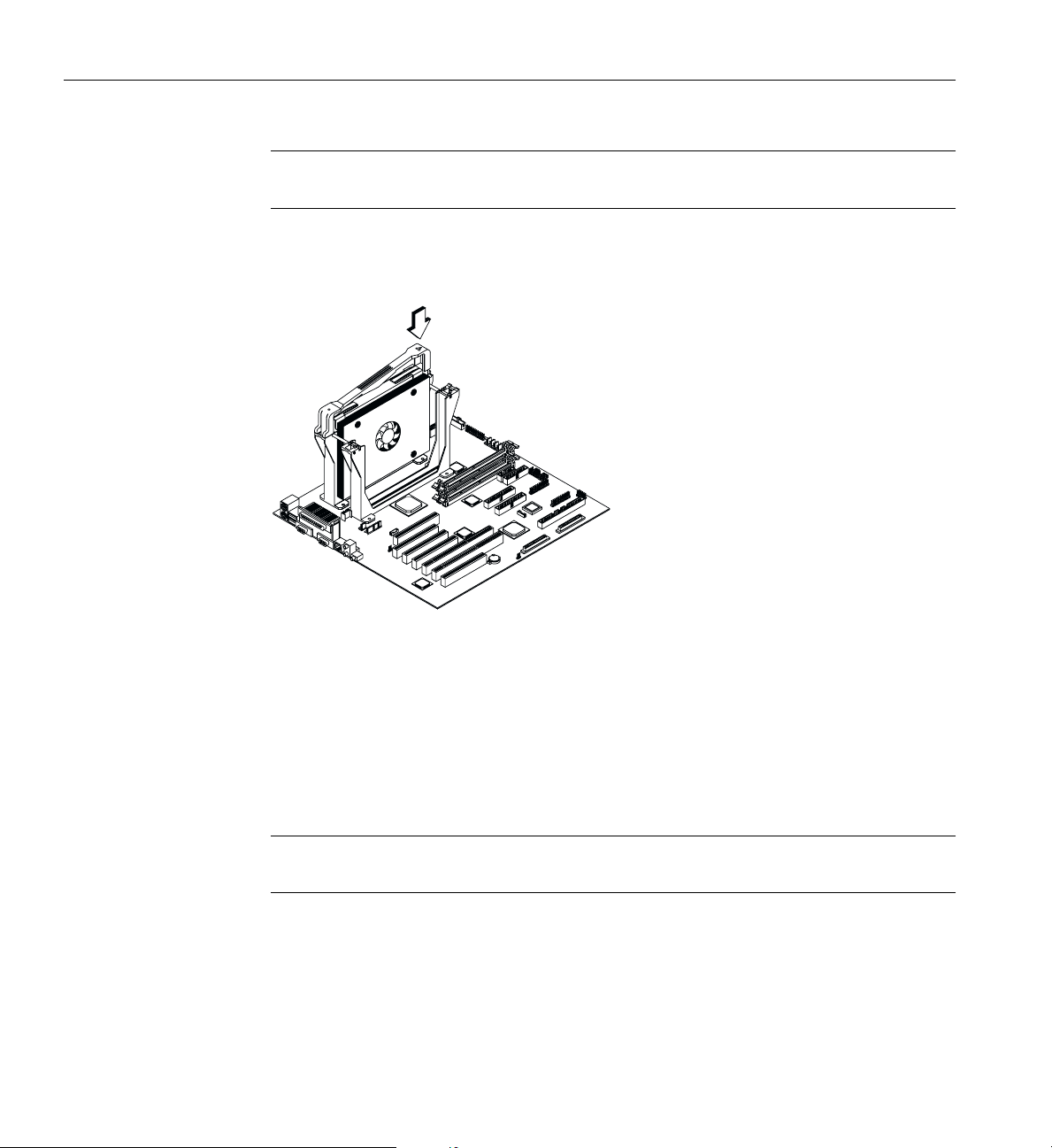
3: System Board
Note: If it is difficult to insert the processor card into the slot, do not force it. The
orientation of the fan/heatsink may be incorrect.
4. Use the retention mechanism cover to secure the processor by pressing it down until
it locks with the retention mechanism, as shown in Figure 3-7.
Figure 3-7 Retention Mechanism Cover
The retention mechanism cover only fits one way. Both shafts of the retention
mechanism and the retention mechanism cover have O and OO signs. Match the O
on the cover with the O on the retention mechanism first, hook them together, insert
the OO side to the retention mechanism, and make sure they are clipped.
5. Connect the 3-pin and 2-pin fan/heatsink cables to the system board. See Figure 3-1
on page 72 for the location of the fan/heatsink connectors.
Caution: The heatsink becomes very hot when the system is on. NEVER touch the
heatsink with any metal or with your hands.
Removing a Processor
Complete the following steps to remove a processor:
80 007-4279-001
Page 97
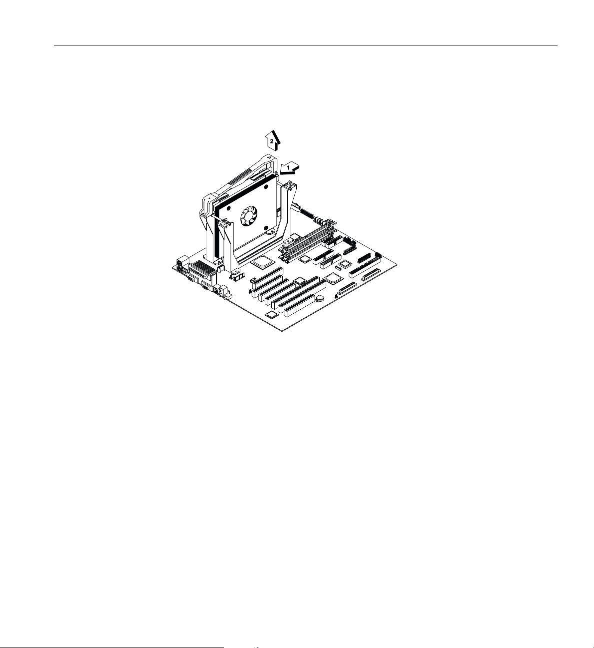
System Component Installation
1. Disconnect the 3-pin and 2-pin fan/heatsink cables from the system board.
2. Unclip the retention mechanism cover, as shown in Figure 3-8.
Figure 3-8 Unclipping Retention Mechanism Cover
3. Flip up both plastic ears of the Pentium III Xeon processor, as shown in Figure 3-9.
This procedure detaches the processor from the socket.
007-4279-001 81
Page 98
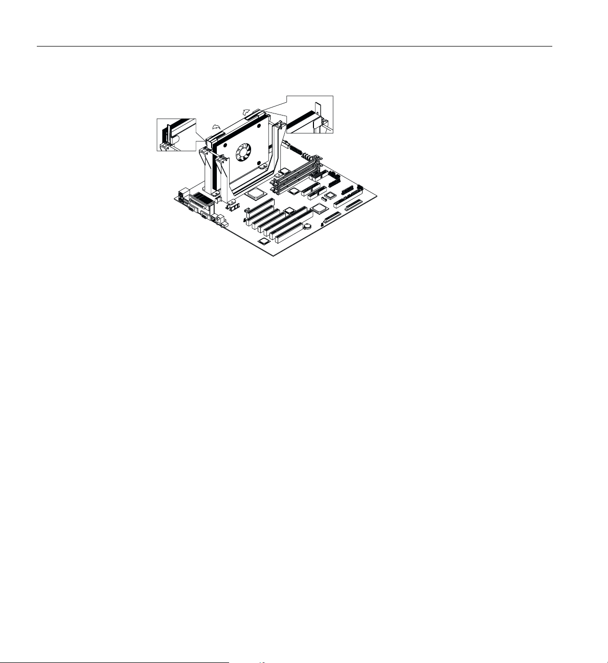
3: System Board
Figure 3-9 Plastic Ears
4. Carefully lift up and remove the Pentium III Xeon processor.
Installing and Removing the Terminator Board
When you are not using a Slot 2 socket, you must install a terminator board into the
empty slot.
Complete the following step to install the terminator board:
1. Position the terminator board over the empty slot, as shown in Figure 3-10.
2. Carefully insert the golden fingers of the terminator board into the slot until the
board fits completely.
82 007-4279-001
Page 99
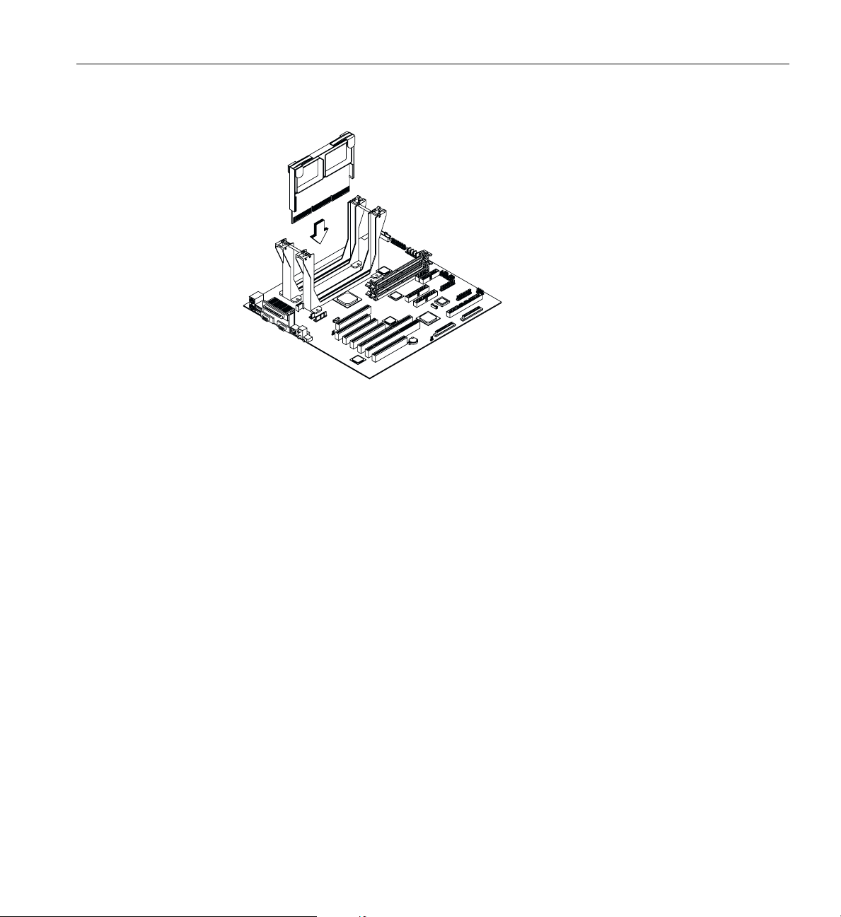
System Component Installation
Figure 3-10 Terminator Board
3. Use the retention mechanism cover to secure the processor by pressing it down until
it locks with the retention mechanism.
4. The retention mechanism cover only fits one way. Both shafts of the retention
mechanism and the retention mechanism cover have O and OO indicators. Match
the O on the cover with the O on the retention mechanism, hook them together,
insert the OO side to the retention mechanism, and make sure they are clipped.
Complete the following steps to remove the terminator board:
1. Unclip the retention mechanism cover.
2. Flip up both plastic ears of the terminator board. This procedure detaches the
terminator board from the socket.
3. Lift up and remove the terminator board.
Installing and Removing Memory Modules
Each of the sockets represents one independent bank. This allows you to install RIMMs
with different capacities to form a configuration.
007-4279-001 83
Page 100
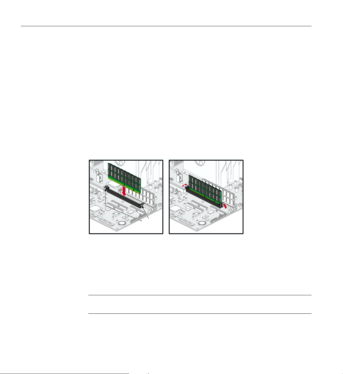
3: System Board
Installing a RIMM
To install a RIMM,align itwith the socket and press it down untilthe holdingclips secure
the RIMM in place.
Note the following important points about installing RIMMs:
• The RIMM socket is slotted to ensure proper installation. If you slip in a RIMM but
it does not completely fit, you may have inserted it the wrong way. Reverse the
orientation of the RIMM.
• RIMMs must be installed in pairs.
• The RIMMs shipped with your system are PC800. When adding additional RIMM
modules, be sure that they are PC800 as mixing RIMMs will cause your system to
default to the slower speed.
Holding
clips
Figure 3-11 Installing a RIMM
Removing a RIMM
To remove aRIMM, press the holdingclips on bothsides of thesocket outward to release
the RIMM.
Note: Place your forefingers on the top of the RIMM before you press the holding clips
to gently disengage the RIMM from the socket.
84 007-4279-001
 Loading...