

Page 1
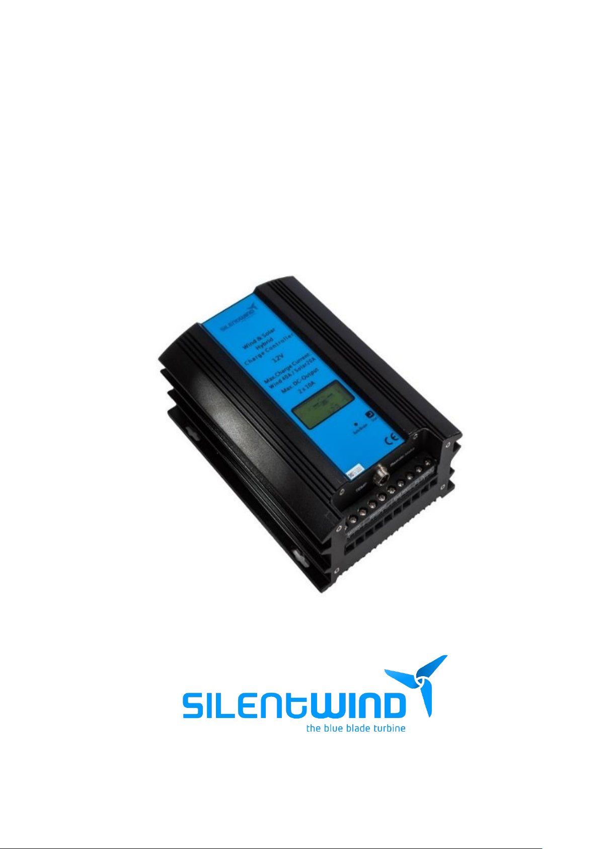
MPPT HYBRID BOOST CHARGE CONTROLLER Rev.1
USER MANUAL
INSTALLATION – OPERATION
February 2019
Page 2

MPPT Charge Controller User Manual - Feb. 2019 2
Page 3

MPPT Charge Controller User Manual - Feb. 2019 3
HYBRID BOOST CHARGE CONTROLLER Rev.1 - MPPT
Congratulation! You have bought a high-quality hybrid charge regulator.
The Hybrid Boost Charge Controller is specially developed for the Silentwind generator.
The Warranty Terms are described in a chapter of this manual. For traceability under the warranty,
please register the Hybrid Boost Charge Controller on our website: www.silentwindgenerator.com
Registering your Hybrid Boost Charge Controller has the following benefits:
- Confirmation of your ownership and safety notifications: by keeping a record of your
registration, we will be able to trace your product and contact you quickly if necessary;
- Product information news: choose to be among the first to hear about our latest product,
helpful advice or product developments
If you have any questions or comments, do not hesitate contact us:
Rulis Eléctrica, Unip. Lda
Loteamento Industrial de Linhares, Lote 19
PT-4805-486 Santo Estevão de Briteiros / Guimarães
Portugal
Phone: 00351-253-572763
Fax: 00351-253-572764
E-mail: [email protected]
Business Hours:
Monday to Friday: 8h00 to 17h00 GMT + 0:00
Welcome to Silentwind family!
The CE marking is a mandatory compliance requirement in EMEA and the UK and although it is self-certified,
testing and evidence to support that testing is preferred from an independent test house.
Machinery Directive 2006/42/EC, Low Voltage Directive 2004/95/EC, Electromagnetic Combability Directive
2004/108/EC. The report and the declaration of conformity are available for inspection on request.
Page 4

MPPT Charge Controller User Manual - Feb. 2019 4
Page 5

MPPT Charge Controller User Manual - Feb. 2019 5
Index
1. IMPORTANT SAFETY WARNINGS AND PRECAUTIONS .................................................................... 6
2. PRESENTATION ............................................................................................................................... 7
3. TECHNICAL DATA ............................................................................................................................ 8
3.1 HYBRID BOOST CHARGE CONTROLLER– ELECTRICAL DATA ................................................... 8
3.2 HYBRID BOOST CHARGE CONTROLLER - MECHANICAL DATA ................................................ 8
3.3 INSTALATION NOTES .............................................................................................................. 8
3.4 PRODUCT STRUCTURE ............................................................................................................ 9
3.5 LCD INFORMATION .............................................................................................................. 10
3.6 LCD DISPLAY ......................................................................................................................... 12
3.7 LOAD OUTPUT MODES ......................................................................................................... 13
4. SAFETY PRECAUTIONS ................................................................................................................... 13
5. INSTALLATIONS ............................................................................................................................. 14
5.1 PACKAGE .............................................................................................................................. 14
5.2 RECOMMENDATIONS ........................................................................................................... 14
5.3 REQUIRED TOOLS AND EQUIPMENT .................................................................................... 14
5.4 CABLES AND FUSES .............................................................................................................. 15
5.5 PHYSICAL INSTALLATION ...................................................................................................... 16
5.6 ELECTRICAL INSTALLATION .................................................................................................. 17
5.6.1 SOLAR PANELS .................................................................................................................. 18
5.6.2 SILENTWIND GENERATOR ................................................................................................ 21
5.7 SETTINGS .............................................................................................................................. 21
5.7.1 SCAN BUTTON .................................................................................................................. 22
5.7.2 SILENTWIND CONTROLLER APP ....................................................................................... 24
5.8 CHECK LIST ....................................................................................................................... 26
6. OPERATION ................................................................................................................................... 26
7. RESET............................................................................................................................................. 27
8. TROUBLESHOTTING ...................................................................................................................... 28
8.1 No display on LCD ................................................................................................................. 28
8.2 No output ............................................................................................................................. 28
8.3 No charging .......................................................................................................................... 29
9. WARRANTY ................................................................................................................................... 30
Page 6

MPPT Charge Controller User Manual - Feb. 2019 6
1. IMPORTANT SAFETY WARNINGS AND PRECAUTIONS
Before using the controller, please read all instructions and cautionary markings on
the unit and this manual. Print or save the manual where it can easily be accessed.
➢ Please study the information thoroughly before starting to install the Hybrid Boost
Charge Controller.
➢ This manual should always be kept near the Hybrid Boost Charge Controller.
➢ Silentwind cannot be held liable for any direct or indirect loss or damage, due to
an incorrect operation or improper device handling.
➢ To avoid a risk of fire and electric shock, make sure the existing wiring is in good
conditions and that the wires are connected tightly
➢ Do not disassemble the Hybrid Boost Charge Controller. Warranty will void.
➢ Never attempt to repair or disassemble the Hybrid Boost Charge Controller or its
parts as there is a danger of fire, electrical shock and possibly death.
➢ Do not change the electrical components and parts by yourself, only Silentwind’s
authorized technicians are able to repair the Hybrid Boost Charge Controller.
➢ Wrong settings can permanently damage your batteries, your charge controller
and your wind generator.
Page 7

MPPT Charge Controller User Manual - Feb. 2019 7
2. PRESENTATION
The Hybrid Boost Charge Controller is a combined wind and solar charge regulator with an inbuilt
micro-controller. The Hybrid Boost Charge Controller enables you to install the Silentwind generator
and solar panels to a maximum power of 300 Watt (peak), that are connected to the deep cycle output
can be automatically switched OFF or ON by a deep cycle protection function.
All operation parameters can be seen on an LCD-display or on a tablet or smartphone over the wireless
connection (Bluetooth). You can set all operating parameters directly on the Hybrid Boost Charge
Controller or over the Silentwind APP available for Android and iOS devices.
The Silentwind generator is a 3 phase AC voltage and in the Hybrid Boost Charge Controller AC is
transformed to DC voltage. The voltage of the Silentwind generator and the Hybrid Boost Charge
Controller must be chosen in accordance with the system voltage.
All types of batteries (Gel, AGM, Acid an Lithium) can be charged.
The Hybrid Boost Charge Controller features:
Solar and Wind - Hybrid charge controller.
Full MPPT point adjustable.
Integrated electronic brake – charge limitation and storm brake.
LCD-display of all relevant working data: W, A, V, Ah.
Seven models of load output settings (not available on 48V version).
Cable connections - screw terminals.
Wireless communication
External wireless antenna for a wider wireless range
Page 8

MPPT Charge Controller User Manual - Feb. 2019 8
3. TECHNICAL DATA
3.1 MPPT HYBRID BOOST CHARGE CONTROLLER– ELECTRICAL DATA
System voltage
12 VDC / 24 VDC / 48 VDC
Max. power input wind generator
600 Watt
Max. current input of the wind generator
40 A / 30 A / 15 A
Max. power input solar
300 Watt
Max. current input solar
20 A / 10 A / 5 A
Max. open circuit voltage input of the solar panel
48 VDC / 48 VDC / 96 VDC
Max. total charge current
60 A
Max. switch off current at LOAD-output (Load)
2 x 10 A
Max. voltage adjustable for the battery types
Acid, Gel, AGM and Lithium
LCD + LED displays
W, A, V, Ah
3.2 MPPT HYBRID BOOST CHARGE CONTROLLER - MECHANICAL DATA
Weight
2.30 kg
Package dimensions
220 x 150 x 83 mm
Cover protection class
IP52
3.3 INSTALATION NOTES
The machine should be kept indoors and well ventilated
Environment temperature
-20 ˚C - +40 ˚C
Altitude
< 1000 m
The space around the device has no other items within
30cm
Can only charge batteries in the same rated voltage range
The charge controller can only be connected to the wind turbine and the PV in the
same rated voltage range
Page 9
MPPT Charge Controller User Manual - Feb. 2019 9
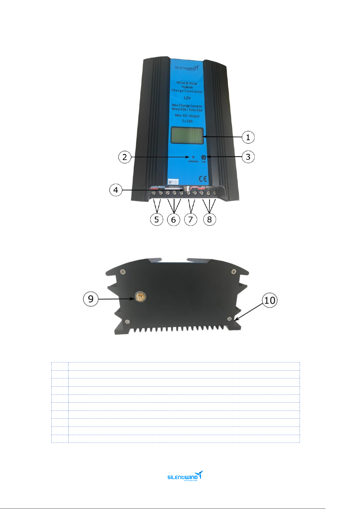
3.4 PRODUCT STRUCTURE
1
LCD Display
2
Brake light
3
Button
4
Temperature compensation sensor connector
5
Battery terminals
6
Silentwind terminals
7
Solar Panel terminals
8
Load terminals
9
External Antenna connector
10
M4 screw install hole
Page 10
MPPT Charge Controller User Manual - Feb. 2019 10
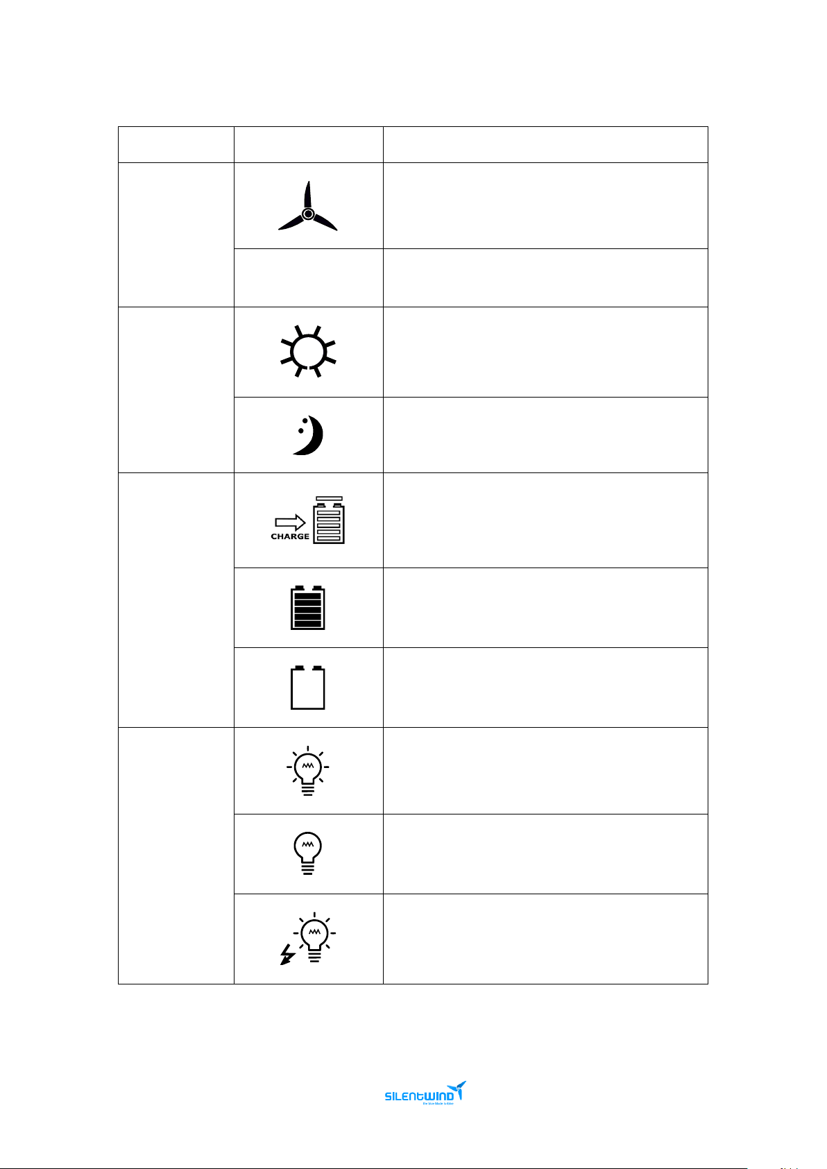
3.5 LCD INFORMATION
Name
Icon
Status
Rotate means wind turbine works normally.
Wind turbine
BRAKE
Brake by hand.
Day.
Solar
Night or Panel Solar is not connected.
Charging.
Battery
Fully charged.
Flickering for over voltage.
Stop flickering when it recovers from over voltage.
Flickering means over-discharge.
Output normally.
Load
No output. Flickering for overload.
Flickering means short circuit.
Page 11
MPPT Charge Controller User Manual - Feb. 2019 11
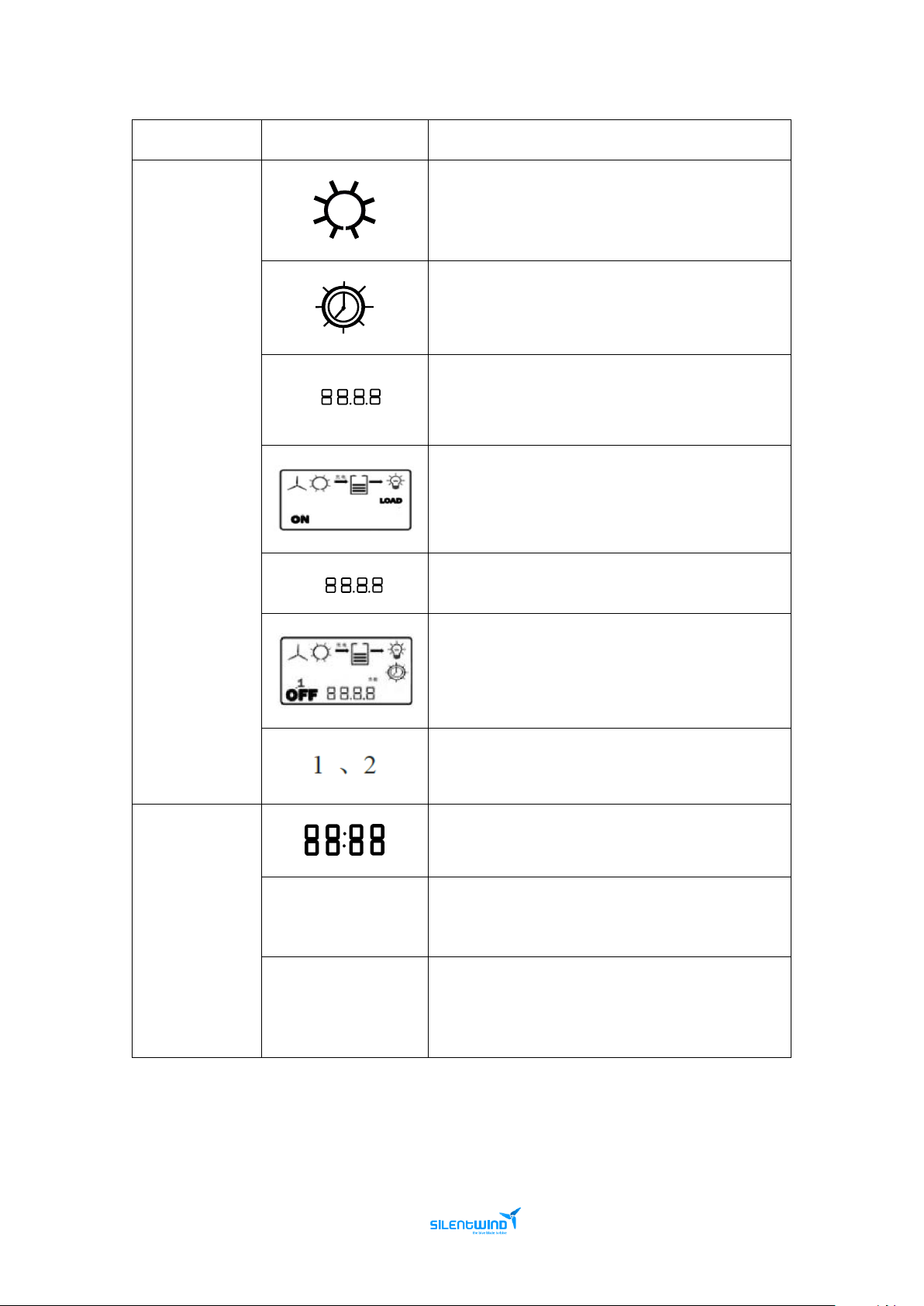
Name
Icon
Status
Light control on/off.
Light control on, time control off.
Light control on voltage.
Load output
When “ON” & “LOAD “appeared, load is
always on.
Control mode
Light control off voltage.
Show “OFF” and time. The time is the control off
time.
Show 2 loops relatively.
Parameters display.
Others
“SET”
Set icon. When it appears, you can set related
parameters by press the browse button.
Unload indicator light
When the machine is in unload or brake status, the
indicator light is red. The light is off when it operates
normally.
Page 12
MPPT Charge Controller User Manual - Feb. 2019 12
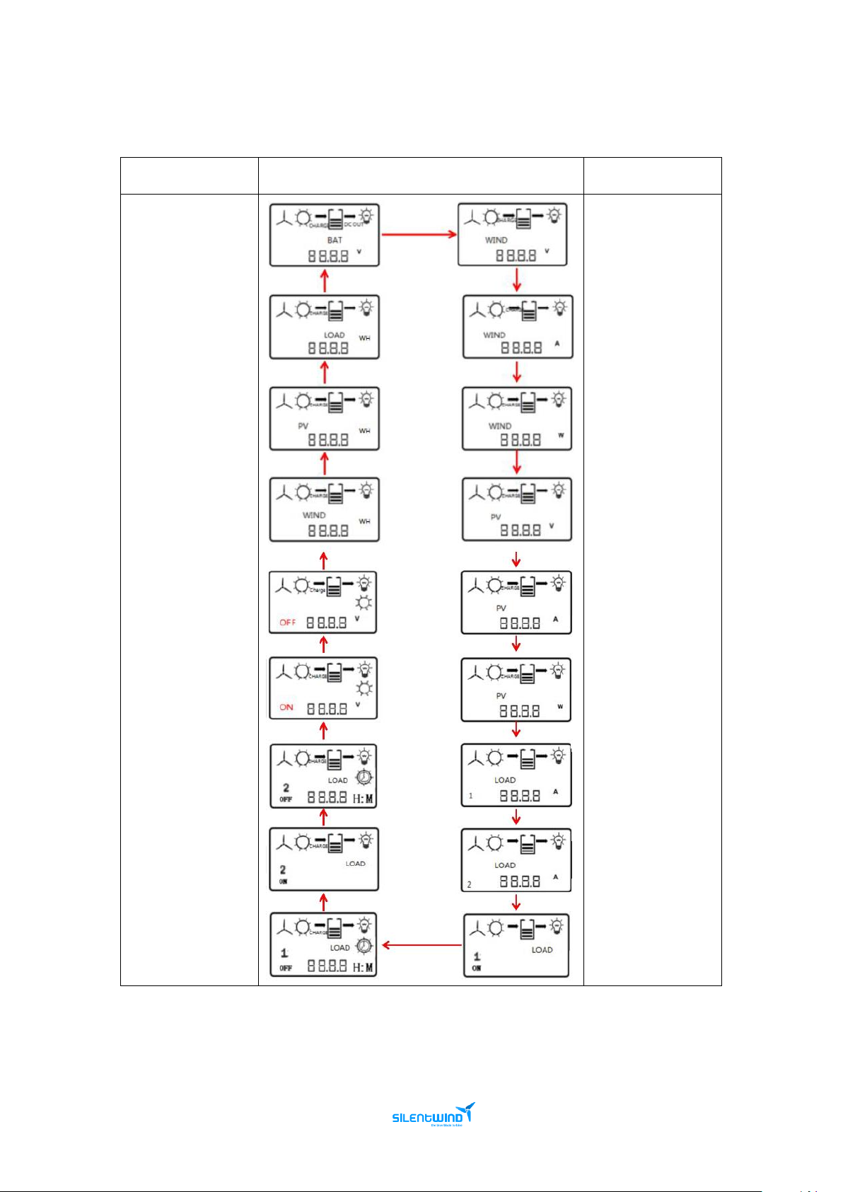
3.6 LCD DISPLAY
Interface
Introduction
Display Interface
Interface
Introduction
Battery Voltage
Accumulative total
electricity
consumption
Accumulative total
Solar generation
capacity
Accumulative total
wind turbine
generation
capacity
Wind turbine
Voltage
Wind turbine
Current
Wind turbine
Power
Solar Panel voltage
Light control off
voltage
Light control on
voltage
*Load 2 Control off
Time
Load 2 output mode
*Load 1 off time
Solar Panel current
Solar Panel power
Load 1 current
Load 2 current
Load 1 output
mode
* It will only be displayed if the setting is turned On.
Page 13
MPPT Charge Controller User Manual - Feb. 2019 13
3.7 LOAD OUTPUT MODES
Load output modes optional that can be set on the LCD display or software
V1
Light control on / off
V2
Light control on, time control off
V3
Light control on/off, time half power
V4
Light control on, time half power, time
control off
V5
Constant On
V6
Constant Off
V7
Constant half power
4. SAFETY PRECAUTIONS
Our primary concern when we developed the Hybrid Boost Charge Controller was your safety. The
information provided is to ensure your safety during installation, operation, and in case of trouble.
Avoid using the Hybrid Boost Charge Controller in direct sunlight, sun exposure, rain, humidity,
acid fog and dust.
Do not use the Hybrid Boost Charge Controller in a place where has flammability and explosive
gas/articles. Beware of flames and sparks.
If you have any additional questions please contact us.
Please keep in mind that liquid acid batteries can emit dangerous explosive gas. If the
place where the Hybrid Boost Charge Controller is installed is close to this kind of
batteries, unsure that has efficient ventilation.
WHEN WORKING IN THE SYSTEM:
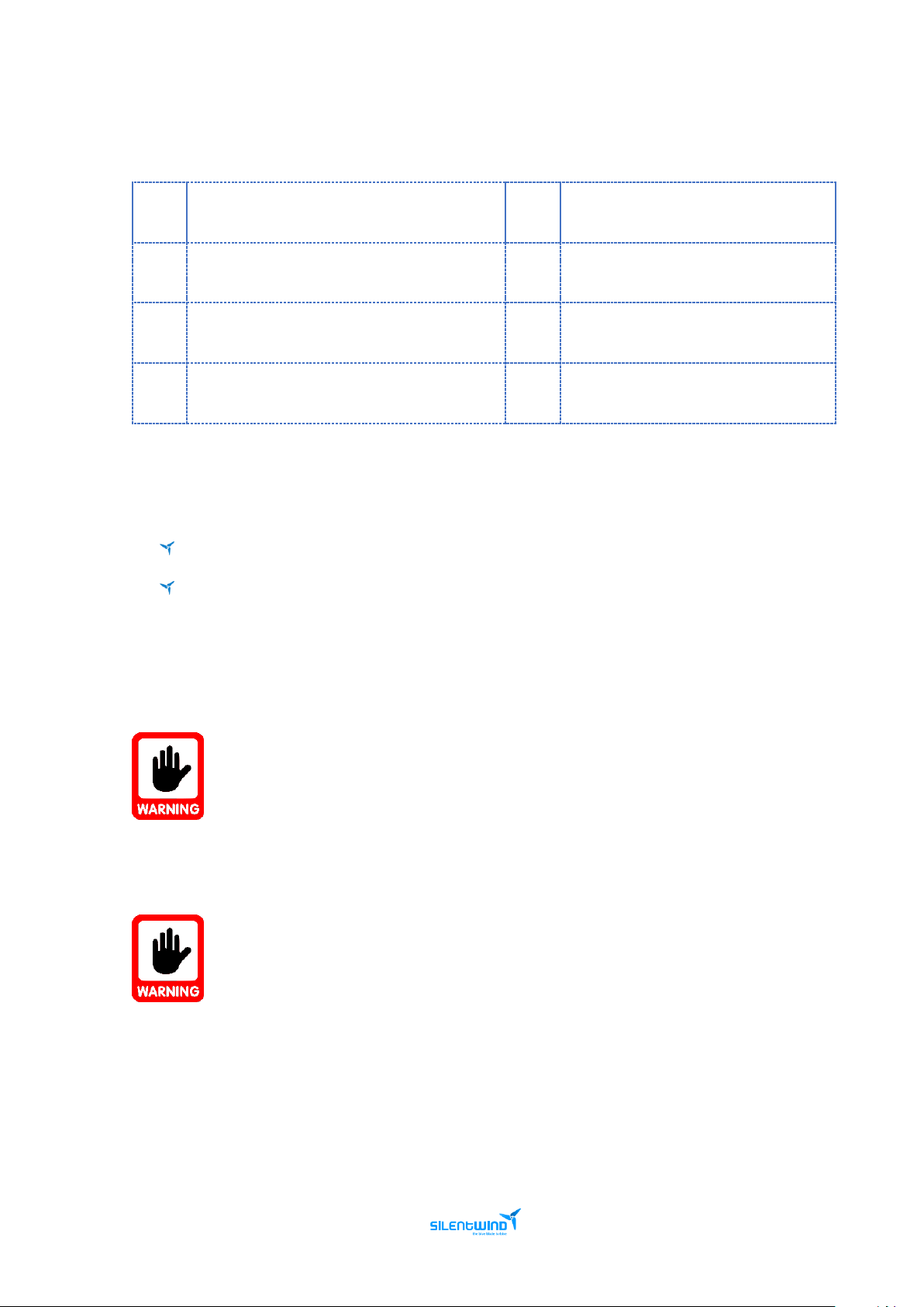
1st Disconnect the Silentwind generator (to avoid risks, once you remove the 3 wires
from the generator, please put at least 2 wires from the generator together to cause
a short circuit and slow down the rotation of the blades).
2nd Disconnect the solar panels if available.
3rd Disconnect Battery. This is very important. Otherwise the Hybrid Boost Charge
Controller will be damaged.
Page 14
MPPT Charge Controller User Manual - Feb. 2019 14
5. INSTALLATIONS
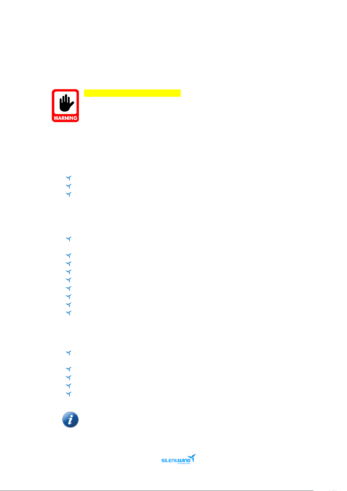
Before installation the Hybrid Boost Charge Controller, find a suitable position indoor to avoid water
entering the controller. The Hybrid Boost Charge Controller must be installed in a place with good
ventilation and heat dissipation.
Plan your installation carefully.
Follow the correct assembly sequence:
1st Charge controller to battery connections
2nd Solar Panels to the charge controller
3rd Wind generator to the charge controller
5.1 PACKAGE
The package includes:
1 unit - Charge controller
1 unit - External Sensor cable
1 unit – External antenna
5.2 RECOMMENDATIONS
Make sure all wires are placed in the correct position or it will damage the charge
controller.
The three AC cables need to have the same cross section and the correct mm²/AWG.
A damaged cable is a severe safety risk. Wires with inadequate cross section can cause fire.
Make sure the electrical connections (crimping) are done 100%.
Any voltage drops can influence the control of brake functions.
Use tinned copper cables for marine installations.
When connecting the Hybrid Boost Charge Controller to the battery, sparks can occur.
A short circuit is to be avoided.
Always ensure enough ventilation in battery location.
5.3 REQUIRED TOOLS AND EQUIPMENT
Cable with the required length and diameter to connect the three AC phases from the
Silentwind generator to the Hybrid Boost Charge Controller.
Connectors for the three-phase cables to connect to the wind generator.
Red and black cable to connect the Hybrid Boost Charge Controller to the battery.
Joint connector for battery cable.
Fuse.
The proper cable sections are listed in the following chapter.
Page 15

MPPT Charge Controller User Manual - Feb. 2019 15
5.4 CABLES AND FUSES
The required cross section of the wires depends on their length and the rated voltage of your system.
Select the location of the mast and measure the distance from the mast top to the battery. Select the
minimum cross section required in the basis of the following tables. The three AC cables need to have
the same cross section.
System voltage 12 Volt
Distance from wind generator to the charge controller (m)
0 - 9
10 - 19
20 - 29
30 - 44
45 - 69
70 - 110
Cable cross section mm2 - AWG
6 – 10
10 – 8
16 – 6
25 – 4
35 – 2
50 – 1
Distance from the charge controller to the battery (m)
0 – 9
10 – 19
20 - 29
30 – 44
45 - 69
70 - 110
Cable cross section mm2 - AWG
16 - 6
24 - 4
35 - 2 - -
-
System voltage 24 Volt
Distance from wind generator to the charge controller (m)
0 - 9
10 - 19
20 - 29
30 - 44
45 - 69
70 - 110
Cable cross section mm2 - AWG
2.5 - 14
4 - 12
6 - 10
10 - 8
16 - 6
25 - 4
Distance from the charge controller to the battery (m)
0 – 9
10 – 19
20 - 29
30 – 44
45 - 69
70 - 110
Cable cross section mm2 - AWG
16 - 6
25 - 4
35 - 2 - -
-
System voltage 48 Volt
Distance from wind generator to the charge controller (m)
0 - 29
30 - 79
80 - 99
100 - 150
Cable cross section mm2 - AWG
2.5 - 14
4 - 12
6 - 10
10 - 8
Distance from the charge controller to the battery (m)
0 – 29
30 – 69
70 - 99
100 - 150
Cable cross section mm2 - AWG
4 - 12
4 - 12
10 - 8
16 - 6-
For protection against high voltage spikes and/or an accidental short-circuit event, fuses must be
installed in the positive (red) wires to the battery. The required value of the fuse depends on the rated
current of the Silentwind generator and solar panels connected to the Hybrid Boost Charge Controller.
We recommend:
Silentwind generator
Max Current (A)
(Silentwind generator + Solar Panel)
Fuse (A)
12V
40 + 20
50 + 25
24V
20 + 10
30 + 15
48V
10 + 5
20 + 10
Page 16
MPPT Charge Controller User Manual - Feb. 2019 16
5.5 PHYSICAL INSTALLATION
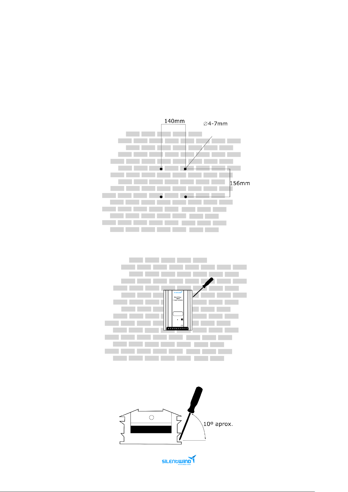
The Hybrid Boost Charge Controller should be installed in a wall using four screws with the panel
upright (if you can read the front panel text horizontally then this is correct).
The side panels and back are a heat sink to dissipate heat, which is why the orientation is important.
To guarantee the lifespan, it is suggested that the space around the device has no other items within
30cm.
1st Drill Size
2nd Fix the controller on the wall with M4 screw
3rd When fix the screw, try to shift the screw driver about 10 angle
Page 17
MPPT Charge Controller User Manual - Feb. 2019 17
5.6 ELECTRICAL INSTALLATION
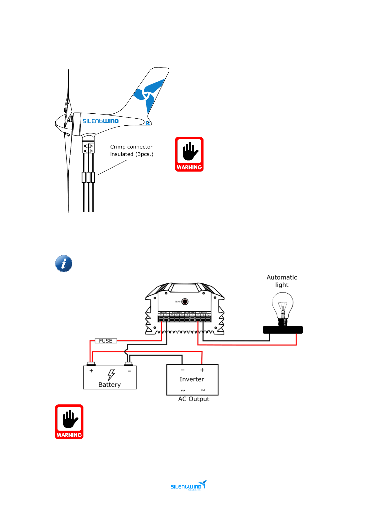
Making an extension of the 3 cables AC, using a crimp
connector insulated will be necessary since the
Silentwind generator will be fixed in the mast and the
Hybrid Boost Charge Controller will not be fixed in the
same place.
If there is enough wind speed when
connecting Silentwind generator, this will
immediately generate electric power at
the end of the 3 AC-wires without being
connected to the Hybrid Boost Charge
Controller. Therefore, we recommend blocking the
Silentwind generator blades with a rope before
connecting the wires to the Hybrid Boost Charge
Controller
Install a fuse between the Hybrid Boost Charge Controller and the battery positive pole as
close as possible to the battery.
It is most important that you first connect the Hybrid Boost Charge Controller to the
battery with the right polarity. The confusion of plus (red) and minus (black) will
definitely destroy your Hybrid Boost Charge Controller.
After the connection of the battery you can connect the solar panel, the Silentwind generator and if
required, a Load Output with 10A maximum on Output 1 and 10A on Output2 with 10A maximum.
Page 18
MPPT Charge Controller User Manual - Feb. 2019 18
5.6.1 SOLAR PANELS
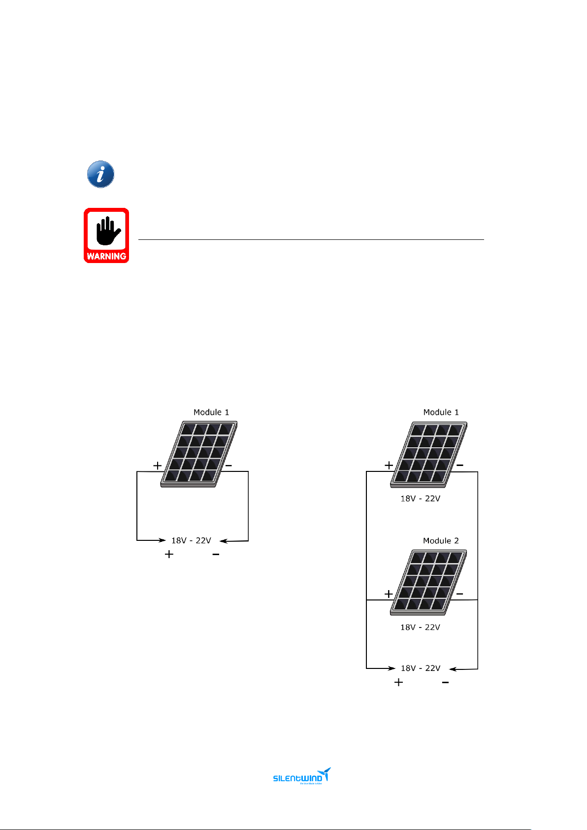
Connect the terminals of solar panels to “SOLAR INPUT” terminals “+” and “-“ on the Hybrid Boost
Charge Controller.
All Solar panels rated voltages on this chapter are open circuit voltages (Voc).
Check your solar panels datasheets for detailed information.
Do not exceed your charge controller’s maximum wattage, voltage and amperage.
12 Volt System
SINGLE PANEL
PARALLEL CONNECTION
Page 19
MPPT Charge Controller User Manual - Feb. 2019 19
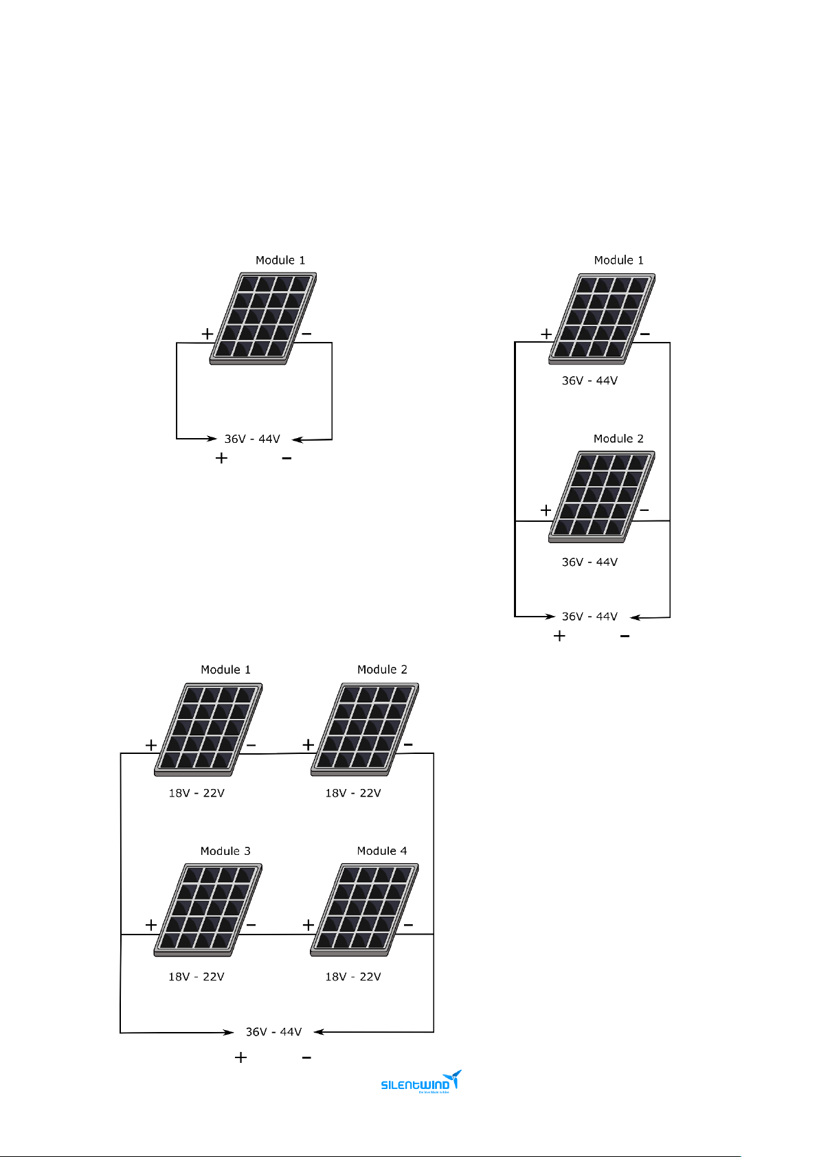
24 Volt System
SINGLE PANEL
PARALLEL CONNECTION
12V PANELS – SERIAL AND PARALLEL CONNECTION
Page 20
MPPT Charge Controller User Manual - Feb. 2019 20
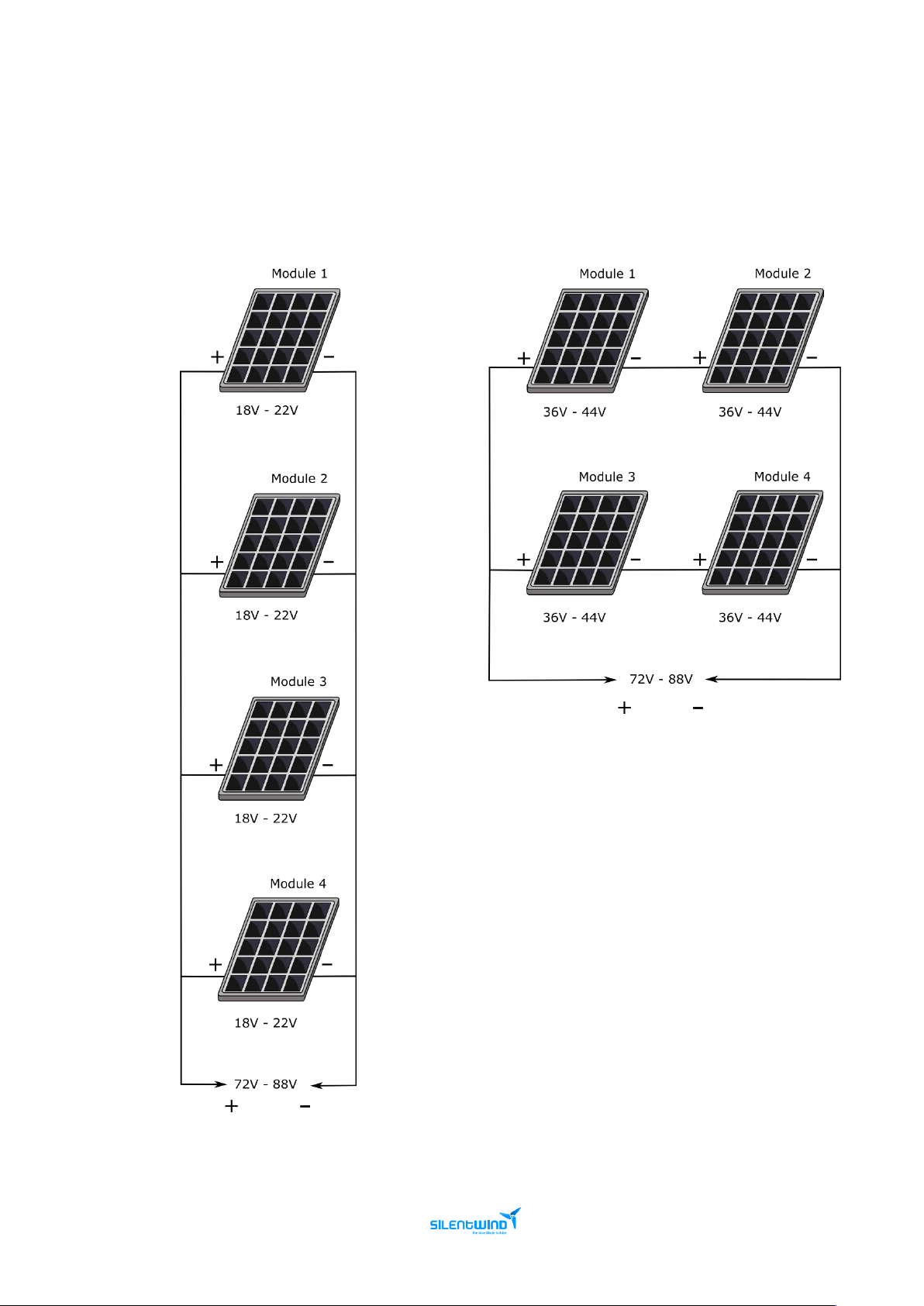
48 Volt System
24V PANELS - SERIAL AND
PARALLEL CONNECTION
12V PANELS – SERIAL AND
PARALLEL CONNECTION
Page 21
MPPT Charge Controller User Manual - Feb. 2019 21
5.6.2 SILENTWIND GENERATOR
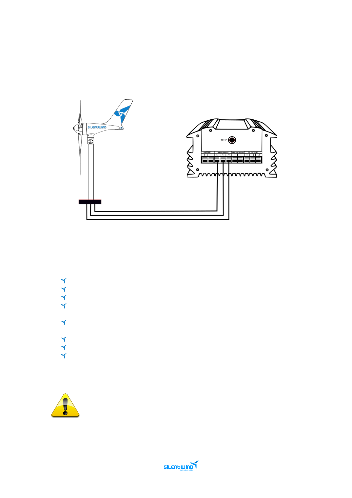
The 3 AC output wires must be connected to the 3-screw terminal on the back of the Hybrid Boost
Charge Controller. In a 3 phase AC system the connection order/polarity does not matter.
5.7 SETTINGS
The Hybrid Boost Charge Controller must be adjusted according the type of battery and according to
your individual requirements.
End of charge Voltage – Batteries maximum voltage.
Overvoltage – Load Output 1 and 2 Voltage protection.
Low Wind Boost – set the boost to achieve an earlier start of charging in to the batteries.
Storm Brake – Maximum amperage allowed. It will limit the maximum rpm speed and
prevents overheating.
Under Voltage Switch Off – To avoid fast discharging, below this value the Outputs are turned
Off.
Under Voltage Recovery On – Above this value, the Outputs are turned On.
Solar Switch Off – Above this value, it will turn the Outputs Off.
Solar Switch On – Below this value, it will turn the Outputs On.
The Break Adjustment of the Hybrid Boost Charge Controller generates internal rising
temperatures that are thermically detected. Therefore, the break time of the Silentwind
Generator will be increased in high wind speeds until the internal temperature is
reduced by dissipation. For this reason, the Hybrid Boost Charge Controller should be
installed on a place as cool as possible. Never install the controller at direct solar
radiation or sunlight.
Page 22
MPPT Charge Controller User Manual - Feb. 2019 22
Values
12V
24V
48V
End of charge voltage
14,4V
28,8V
57,6V
Overvoltage
16V
32V
64V
Low Wind Boost
3V
4V
10V
Storm Brake
32A
16A
9A
Under Voltage Switch Off
10,8V
21,6V
43,2V
Under Voltage Recovery On
12V
24V
48V
Solar Switch Off
1,5V
3V
6V
Solar Switch On
1V
2V
3V
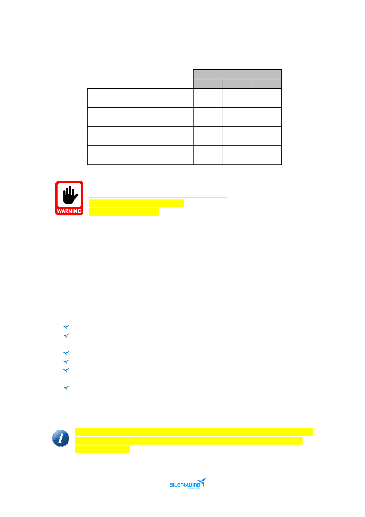
The above table is for standard GEL and AGM batteries. Costumers must always check
the battery manufacturer settings recommendations.
The End of Charge Voltage is critical.
The Storm Brake is critical.
Silentwind cannot be held responsible for bad parameter settings that might permanently damage
your batteries, your charge controller and your wind generator.
If you need to change the parameters, it can be done directly on the Hybrid Boost Charge Controller
or through APP.
5.7.1 SCAN BUTTON
How the SCAN button works:
Press momentarily to change between screens
Press for 2s to enter SET mode (LCD shows “SET”, settings will vary according to the screen),
pressing again for 2s will exit and save the SET mode
Pressing the scan button on SET mode will adjust the parameters
Press de button for 5s to turn the Brake On
Press the button for 8s to fix the voltage degree, and then you can enter the setting
interface after it shows “24” or “12”. (Not recommended, leave it as it is)
Press the button for 10s to reset to factory defaults and the 8888 number will be displayed
on the LCD. Stop pressing the button and then click it momentarily to turn the charge
controller to normal operation.
The value is looped through several parameters. So, if the value you want to set is less than
the one it showed on the LCD at present, you just need increase it and let it back to the
small value you need.
Page 23
MPPT Charge Controller User Manual - Feb. 2019 23
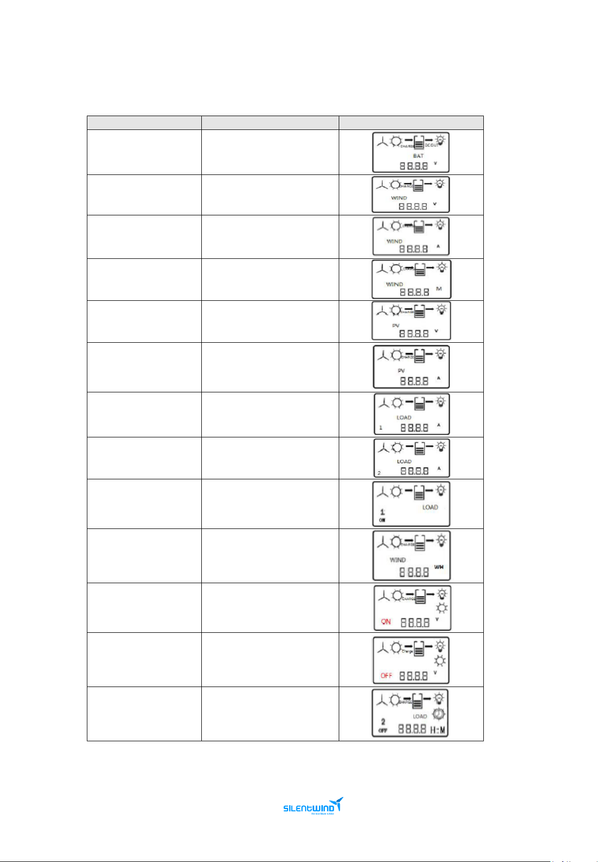
See the following table for specific parameter setting.
Scroll down to the display you want and press for 2s to go to the desired settings.
After setting the parameters, press for 2s to leave the SET mode.
Settings
Interface Introduction
Display Interface
End of charge voltage
Battery Voltage
Over-voltage
Wind turbine Voltage
Storm Brake
Wind turbine current
Do not change !!!
Wind turbine power
Low-wind boost
Solar panel voltage
Not enabled
Solar panel current
Under voltage switch-off
Load 1 current
Under voltage recovery
Load 2 current
8 output control modes
Load 1 output mode
Do not change !!!
Wind turbine power
Night voltage point
Light control on voltage
Day voltage point
Light control off voltage
Time control duration
Load 2 control off time
Page 24
MPPT Charge Controller User Manual - Feb. 2019 24
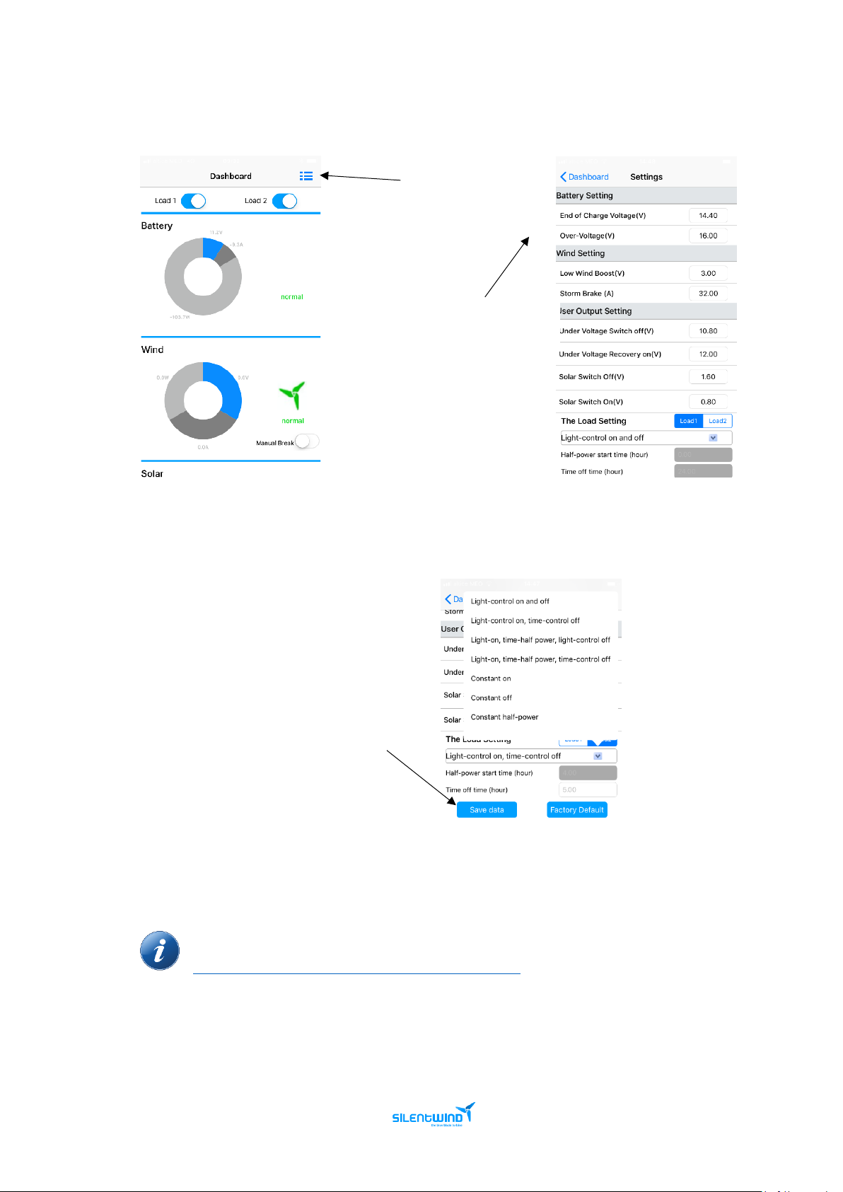
5.7.2 SILENTWIND CONTROLLER APP
The Silentind Controller APP is available on the Google Play for Android devices and Apple Store for
iOS devices. Go to your app store, according the operating system of your phone, and search for:
SILENTWIND.
Download the app and install it as any other APP. Compatibility information is displayed at the
download section.
Please read the APP Terms and Conditions carefully.
After installing the APP make sure Bluetooth is enable in your phone and the controller is ON and near
your phone.
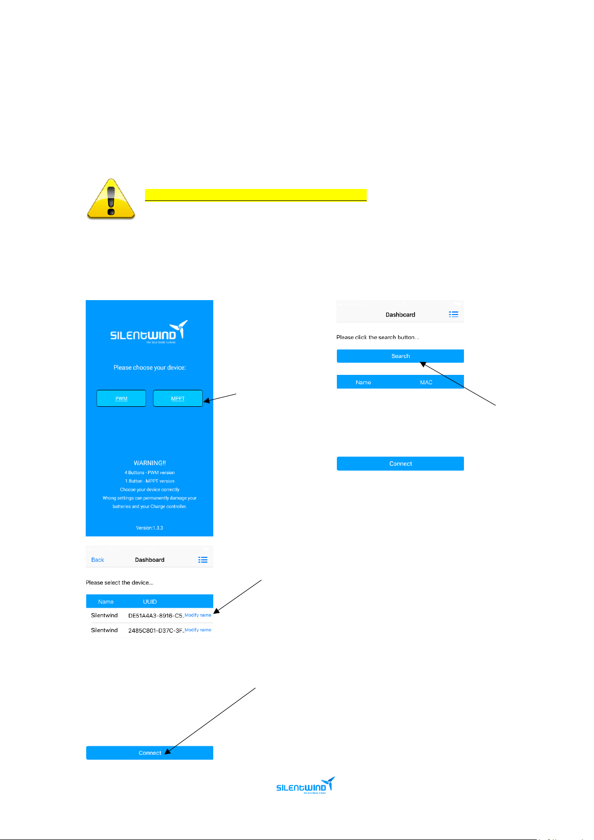
Execute the program and follow the instructions:
1. Choose MPPT
2. Click on Search
3. Choose your device
4. Click on Connect and wait until the
dashboard is displayed
Page 25
MPPT Charge Controller User Manual - Feb. 2019 25
The above pictures were taken from the v1.3.3 version and can differ from the present
versions. For further information please visit our download section at:
https://www.silentwindgenerator.com/en/download/
6. Click on settings
5. Set the parameters
accordingly
7. Click on Save Data
Page 26
MPPT Charge Controller User Manual - Feb. 2019 26
5.8 CHECK LIST
Before getting the Hybrid Boost Charge Controller started, check the correct mounting and installation
according to the following check list:
Electric Installation
Enough ventilation is provided?
The electrical connections (crimping) were done correctly?
All wires are correctly placed?
The wires have the correct cross section: Silentwind generator and battery?
The fuse was installed between the Hybrid Boost Charge Controller and the battery?
Hybrid Boost Charge Controller
Fastened securely to the mounting location?
All screw terminals firmly tightened?
6. OPERATION
If windspeed is enough, the Silentwind generator should start charging. You can control this on the
LCD display of the Hybrid Boost Charge Controller or from your smartphone or tablet using Silentwind
generator APP available on Android and iOS devices.
To brake the Hybrid Boost Charge Controller manually, press the button for 5s to activate the brake
status.
If the End of charge voltage and/or the Brake Storm Voltage values is/are reached, the
Silentwind generator will stop for approximately 10 minutes. After that period, the charge
controller will check if it’s safe to turn the Brake to Off.
If the capacity of the batteries is less than 150 Ah, or old batteries that have lost their
original capacity, the point of max. voltage can be reached very fast although the battery
is not fully charged yet. In this case it can be useful to connect an electric consumer to
the Load-output, as this will reduce the voltage and thus prevent that the break mode is
activated too early.
Page 27

MPPT Charge Controller User Manual - Feb. 2019 27
7. RESET
Reset the Hybrid Boost Charge Controller: Please press the reset button for 10s.
Total reset of The Hybrid Boost Charge Controller:
Follow the correct assembly/disassembly order.
o How to disconnect the charge controller (wind, solar, battery):
1st Disconnect the Silentwind generator (to avoid risks, once you remove the 3 wires from the
generator, please put at least 2 wires from the generator together to cause a short circuit and slow
down the rotation of the blades).
2nd Disconnect the solar panels if available.
3rd Disconnect Battery.
Following this order sequence is very important, otherwise the Hybrid Boost Charge Controller
will be damaged.
o Leave the Hybrid Boost Charge Controller for at least 10 min. to rest to dissipate all
energy.
o After 10 minutes connect the cables on the inverse order:
1st Connect the Hybrid Boost Charge Controller to the battery;
2nd Connect solar panels;
3rd Connect the Silentwind generator and insert the parameters again.
Page 28
MPPT Charge Controller User Manual - Feb. 2019 28
8. TROUBLESHOTTING
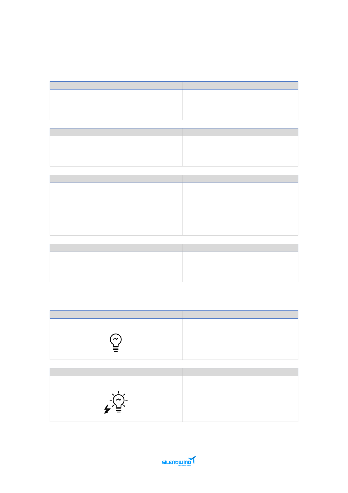
8.1 No display on LCD
Description
Possible reasons and solutions
The connection between the battery and the
controller is not tight.
Check the wiring and reconnect it.
Description
Possible reasons and solutions
DC breaker is not on between battery and
controller.
Turn on the breaker.
Description
Possible reasons and solutions
Low battery voltage.
- The system parameters are not matched
correctly. Recheck the label and
parameters on the machine.
- The battery does not work. Change for a
new one.
Description
Possible reasons and solutions
The battery is connected negatively to the
controller.
Need change the internal fuse in controller
and reconnect to the battery.
8.2 No output
Description
Possible reasons and solutions
Flicker means overload.
Check if the load connection is normal.
Remove the over load, press the set button
on the load interface to recover output.
Description
Possible reasons and solutions
Load short circuit.
Check the load and press the set button on
the load interface to recover output.
Page 29

MPPT Charge Controller User Manual - Feb. 2019 29
8.3 No charging
Description
Possible reasons and solutions
The connection cable between wind turbine and
controller is loose.
Reconnect the cable tightly.
Description
Possible reasons and solutions
Wind turbine output voltage do not reach the
charging voltage.
Check if the system voltage is correct.
Description
Possible reasons and solutions
The connection cable between solar panel and
controller is loose.
Reconnect the cable tightly.
Description
Possible reasons and solutions
Wind turbine is in “Brake” status.
- If it breaks automatically, wait the wind
turbine recover.
- if it breaks manually, press the button for
5s to release the brake status.
Description
Possible reasons and solutions
The solar panel is connected wrongly to the
controller.
Reconnect the cables.
Description
Possible reasons and solutions
Solar Panel output voltage is not in accordance
with the system voltage.
Check the Solar Panel output and the
system parameters.
Description
Possible reasons and solutions
Battery is already fully charged.
See if the battery has reached its over
voltage point.
Page 30

MPPT Charge Controller User Manual - Feb. 2019 30
9. WARRANTY
The Hybrid Boost Charge Controller is designed to be in good working order, but if it is found to be
defective within the warranty period, repair service will be provided free of charge by Rulis Electrica,
Unip. Lda.
Hybrid Boost Charge Controller
Period of warranty
24 months
The limited warranty begins on the purchase date.
Free repair service may only be obtained by providing the warranty card and original purchase invoice
issued to the customer by the retailer. The warranty card must state the purchaser s name and
address, the retailer s name and address, the serial number and the date of purchase of the product.
If you experience any problem with your Hybrid Boost Charge Controller, please contact:
- Rulis Electrica – [email protected]
- Authorized service dealers – https://www.silentwindgenerator.com/en/silentwind-in-the-
world/
After Rulis Electrica is notified, the technical department will make all reasonable efforts via phone
and email to ascertain the natures of the problem to determine whether any part is defective for
purpose of coverage under this Limited Warranty. There is no charge for such diagnosis. Any repair
or replacement will be provided only after Rulis Electrica´s diagnosis and its agreement to the
defective condition.
Rulis Electrica, Unip. Lda, reserves the right to repair free of charge the defective part or exchange
free of charge the defective part with a new or refurbished part or Hybrid Boost Charge Controller
that is new or equivalent to new in performance and reliability and is at least functionally
equivalent to the original Hybrid Boost Charge Controller part.
Any costs of secure transportation of the product to Rulis Electrica, Unip. Lda authorized service
partners will be borne by the customer. Repaired or replaced Hybrid Boost Charge Controller and
replacement part will be delivered to the customer at Rulis Electrica, Unip. Lda expense.
If a warranty claim is invalid for any reason, the customer will be informed of the repair and return
freight charges for prior approval. If the customer refuses to approve repair charges, return freight
charges may apply.
When a Hybrid Boost Charge Controller part is replaced for a new or remanufactures part, such
new or remanufactures part becomes customer´s property and replaced part becomes Rulis
Electrica, Unip. Lda property. Customer property remaining at Rulis Electrica Lda repairs facilities
for more than ninety (90) days without required customer approval of return freight charges,
becomes the property of Rulis Electrica Unip, Lda
Page 31

MPPT Charge Controller User Manual - Feb. 2019 31
Rulis Electrica Lda does not warrant the following:
- Defects caused by modifications carried out without approval.
- Damage caused by improper use, handling or operation, in particular defects caused by improper
installation and installation on inadequate masts or support structures.
- Accidents or disasters or any cause, including but not limited to lightning, flooding, fire etc.
- Costs for disassembly and reassembly of the product to enable shipment for warranty reasons
Disclaimer of Warranty
This Limited Warranty gives you specific legal rights, and you may also have other rights which vary from
country to country and state to state. TO THE EXTENT PERMITTED BY LAW, THIS EXPRESS LIMITED
WARRANTY AND THE REMEDIES SET FORTH ABOVE ARE EXCLUSIVE AND IN LIEU OF ALL OTHER
WARRANTIES, REMEDIES AND CONDITIONS, WHETHER ORAL, WRITTEN, STATUTORY, EXPRESS
OR IMPLIED. AS PERMITTED BY APPLICABLE LAW, Rulis Electrica, Unip. Lda. DISCLAIMS ANY AND ALL
STATUTORY OR IMPLIED WARRANTIES, INCLUDING, WITHOUT LIMITATION, THE IMPLIED
WARRANTIES OF FITNESS FOR A PARTICULAR PURPOSE, MERCHANTABILITY, NONINFRINGEMENT AND WARRANTIES AGAINST HIDDEN OR LATENT DEFECTS. IF Rulis Electrica, Lda.
CANNOT LAWFULLY DISCLAIM STATUTORY OR IMPLIED WARRANTIES THEN, TO THE EXTENT
PERMITTED BY LAW, ALL SUCH WARRANTIES SHALL BE LIMITED IN DURATION TO THE DURATION
OF THIS EXPRESS LIMITED WARRANTY. Rulis Electrica, Lda. does not grant to any person or entity
(including its field representatives, dealers or distributors) the authority to create for it any obligation or liability
in connection with your Hybrid Boost Charge Controller. Limitation of Liability EXCEPT AS PROVIDED IN
THIS EXPRESS LIMITED WARRANTY AND TO THE MAXIMUM EXTENT PERMITTED BY LAW, UNDER
NO CIRCUMSTANCES WILL Rulis Electrica, Unip. Lda., OR ITS AFFILIATES, SUPPLIERS, DEALERS,
DIRECTORS, OFFICERS, EMPLOYEES, OR AGENTS (THE “RELEASED PARTIES”) BE LIABLE OR
RESPONSIBLE FOR, EVEN IF SUCH RELEASED PARTY HAS BEEN ADVISED OF THE POSSIBILITY OF
SUCH DAMAGE, ANY DIRECT, SPECIAL, INCIDENTAL OR CONSEQUENTIAL DAMAGES RESULTING
FROM ANY BREACH OF WARRANTY OR CONDITION, OR UNDER ANY OTHER LEGAL THEORY OR
FORM OF ACTION (WHETHER IN CONTRACT, TORT (INCLUDING NEGLIGENCE), STRICT LIABILITY
OR OTHERWISE), INCLUDING, BUT NOT LIMITED TO, ANY LOSS OF USE, INTERRUPTION OF OR
LOSS OF BUSINESS, LOST OF ACTUAL OR ANTICIPATED PROFITS (INCLUDING LOSS OF PROFITS
ON CONTRACTS), LOSS OF REVENUE, LOSS OF THE USE OF MONEY, LOSS OF ANTICIPATED
SAVINGS, LOSS OF OPPORTUNITY, LOSS OF GOODWILL, LOSS OF REPUTATION, LOSS OF, DAMAGE
TO OR CORRUPTION OF DATA, OR ANY INDIRECT ORCONSEQUENTIAL DAMAGES HOWEVER
CAUSED, INCLUDING THE REPLACEMENT OF EQUIPMENT AND PROPERTY, BODILY INJURY OR
DEATH.
(Note: some states do not allow the exclusion or limitation of incidental or consequential damages, so these
limitations may not apply to you.) The total cumulative liability to Customer, from all causes of action and all
theories of liability, will be limited to and will not exceed the purchase price of the Hybrid Boost Charge
Controller paid by Customer.
Page 32

MPPT Charge Controller User Manual - Feb. 2019 32
9.1 WARRANTY CARD
Owners Name
Purchaser Address
Purchase Date
Hybrid Boost Charge Controller serial
number
Retailer Name
Retailer Address
9. AFTER-SALES SERVICE (*)
Before requesting after-sales support, please read the user manuals carefully. Check also for our
troubleshooting documents at our download section.
Check regularly for updates.
The requests must be done were you bought the SILENTWIND Pro.
If for some reason the request is done directly to SILENTWIND, it will be first submitted for approval.
The requests can be done through our online Helpdesk platform at: https://silentwind.vhdeu.com
or sending an email to: [email protected] or for sales: [email protected] .
To avoid any delays, please fill all necessary information to track the problem and validate the
warranty if needed.
9.3 ONLINE SUPPORT
Use our online ticket support for a faster response!
Please always provide the above information requests to speed up your claim.
You can access directly to our support portal at https://silentwind.vhdeu.com/index.php or you
can send an email to [email protected].
For sales, you can use our support portal and choose the sales department, or you can send an
email to [email protected].
 Loading...