

SILENT KNIGHT 9500 Installation Manual

SILENT KNIGHT
Desktop Digital
MODEL 9500
Alarm Receiver
Installation Manual
Part Number 151059F, 01/03

Content
Section 1
System Overview .............................................................................................................................. 1-1
1.1 Features .................................................................................................................................................... 1-1
Hardwa re: ....... ............ ......... ............. ............ ............ .......... ............ ............ ............ ....................... 1-1
Software: ....................................................................................................................................... 1-2
1.2 Optional Accessories ................................................................................................................................ 1-2
1.3 Formats Compatible with the 9500 .......................................................................................................... 1-3
1.4 9500 Supported SIA Digital I-III Levels ................................................... ............................. ................. 1-4
1.5 How to Us e th i s Manual ... .. ..................................... .. ... ............................................................................ 1-5
1.6 Terminology ............................................................................................................................................. 1-5
1.7 What’s in the Box .................................................................................................................................... 1-6
1.8 How to Contact Silent Knight .................................................................................................................. 1-6
Section 2
Agency Requirements ............................................................................................................... 2-1
2.1 Telephone Requirements .............................. .............. ..................................... .............. ........................... 2-1
2.2 FCC Warning ........................................................................................................................................... 2-1
2.3 UL Requirements ..................................................................................................................................... 2-2
2.3.1 Hard w ar e R eq u irements ..... .. ............................................................................................................ 2-2
2.3.2 Operational Requirements ................................................................................................................ 2-2
2.3.3 Progr amming R eq u ir e m en t s . ............................................................................................................ 2-2
Section 3
Installation ................................................................................................................................................. 3-1
3.1 Environmental specifications ................................................................................................................... 3-1
3.2 Electrical Specifications ........................................................................................................................... 3-1
3.3 Over view ......... .......... ............ ............ ............ .......... ............ ............ ............ .......... ................................... 3-2
3.4 Line Card Installation ............................................................................................................................... 3-4
3.5 Removing Line Cards .............................................................................................................................. 3-5
3.6 Telephone Line Connection .......... ......................... .............. .............. ......................... ............................. 3-6
3.7 Parallel Printer Connection ...................................................................................................................... 3-7
3.7.1 Printer Cable Pin-Outs ...................................................................................................................... 3-8
3.7.2 Com Po r ts 1 & 2 ......... ...................................................................................................................... 3-8
3.7.3 Remote Alert Output ......................................................................................................................... 3-9
3.8 AC Power Cord Connection .................................................................................................................. 3-10
3.8.1 Using Standard Power Cord ........................................................................................................... 3-10
3.8.2 Using UL Listed AC Power Connection ........................................................................................ 3-10
3.8.3 Switching to a 230 VAC Power Supply ..................... ........................... ......................................... 3-12
3.8.4 How to Verify Earth Ground .......................................................................................................... 3-13
3.9 Bat tery Connection ...................................... .............. ..................................... .............. ......................... 3-14
3.10 Automation Computer Connection ........................................................................................................ 3-16
3.10.1 Computer Port Baud Rate Selection ............................................................................................... 3-16
151059 i

Model 9500 Central Station R eceiver In stallation/Operation Manual
Section 4
Operation ..................................................................................................................................................... 4-1
4.1 Touchpad Function Buttons ..................................................................................................................... 4-1
4.2 Displ ays . ... .... ..... ..... ... .... ..... ..... ... .... ..... ..... ... .... ..... ..... ... .... ..... ..... ... .... ..... ..... ... .... ..... ................................. 4-3
4.2.1 LED Disp l ay s ..... ................. ....................................................................................... ....................... 4-3
4.2.2 LCD Status Display .......................................................................................................................... 4-3
4.2.2.1 Adjusting LCD Contrast ........................................................................................................ 4-4
4.2.2.2 LCD Abbreviations ................................................................................................................ 4-5
4.3 Initial System Power Up .......................................................................................................................... 4-6
4.4 Log On / Log Off ..................................................................................................................................... 4-7
4.4.1 Installer Profile ................................................................................................................................. 4-7
4.4.2 Oper at or Pr o fi l e ..... ... ........................................................................................................................ 4-7
4.4.3 Defau l t U ser Co d e s .......... ... .. ............................................................................................................ 4-8
4.4.4 How to log on the system. ................................................................................................................ 4-8
4.4.5 How to log off the system. ................................................................................................................ 4-9
4.5 Modes of Operation ............................................................................................................................... 4-10
4.5.1 Norma l M o d e ......... ... .. ................................................................................................ .................... 4-10
4.5.1.1 Manual Operation ................................................................................................................ 4-10
How to Manually Acknowledge Calls: ....................................................................................... 4-10
4.5.1.2 Automatic Operation ............................................................................................................ 4-10
4.5.1.3 Log Only .............................................................................................................................. 4-10
4.5.2 Program Mode ................................................................................................................................ 4-10
4.6 Main M en u ........ ..................................................................................................................................... 4-11
4.6.1 How to display the Main Menu ...................................................................................................... 4-11
4.6.2 How to Ma n eu v er Th ro ug h M ai n M en u .. .......................................................................................4-12
4.6.3 Call History ..................................................................................................................................... 4-13
4.6.4 System History ................................................................................................................................ 4-13
4.6.5 System Info ..................................................................................................................................... 4-14
4.6.6 Set Time & D at e ........ .................................................................................................................... 4-15
4.6.7 System Restart ................................................................................................................................ 4-16
4.6.8 Printer Menu ................................................................................................................................... 4-17
4.6.8.1 Print Report .......................................................................................................................... 4-18
How to Print Call History ............................................................................................................4-18
How to Print System History ...................................................................................................... 4-19
How to Print System Configuration ............................................................................................ 4-20
How to Print a Test Page .............................................................................................................4-21
4.6.8.2 Edit Ev en t Fo rm a t .... .. ................................................................................................ .......... 4-21
4.6.8.3 Configure Printer .................................................................................................................. 4-23
4.6.9 Program Menu ................................................................................................................................ 4-24
4.6.10Diagnosti cs Menu .... .............. ............. .............. .............. ............. .............. ..................................... 4-24
4.6.10.1 Phantom Menu ..................................................................................................................... 4-25
4.6.10 .2 M essage Qu e ....... .. ............................................................................................................... 4-26
4.6.10.3 Event Log ............................................................................................................................. 4-26
4.6.10.4 Format .................................................................................................................................. 4-27
4.6.10 .5 LC De b u g M o d e .. ................................................................................................................. 4-27
4.6.10.6 LC Statistics ......................................................................................................................... 4-28
4.6.10 .7 Po r t S ta tu s ............................................................................................................................ 4-29
4.7 Liste n- I n an d Han g U p ..... ...................................................................................................................... 4-30
4.7.1 Extend ( Co mmon) Li st en - I n Oper a ti o n ........ ... ......... ...................................................................... 4-30
4.7.2 PBX Op er at i on ..... ....................................................................................................... .................... 4-31
4.8 Testi ng th e Sys t em ................................................................................................................................. 4-31
ii 151059

Content
Section 5
Programming ......................................................................................................................................... 5-1
5.1 How to Enter Program Mode ................................................................................................................... 5-1
5.1.1 Progr amming F ie l ds .......................................................................................................................... 5-1
5.1.2 How to Maneuver Around in Program Mode ........ ............................. .. ............................. ...............5-2
5.2 Progr amming C ho i ce s . ............................................................................................................................. 5-2
5.3 General Options ....................................................................................................................................... 5-3
5.3.1 Operation Mode ................................................................................................................................ 5-7
5.3.1.1 How to change the operation mode ........................................................................................5-8
5.3.2 Display Options ................................................................................................................................ 5-9
5.3.2.1 How to Change Language Display ...................................................................................... 5-10
5.3.2.2 How to Change Time Format Display ................................................................................. 5-11
5.3.2.3 How to Change Date Format Display .................................................................................. 5-11
5.3.2.4 How to Turn “On” or “Off” Daylight Savings. ................................................................... 5-11
5.3.2.5 How to Edit ITI Options ...................................................................................................... 5-12
5.3.2.6 How to Edit Format (FMT) Options .................................................................................... 5-13
5.3.2.7 How to Set Hold Last Event ................................................................................................ 5-13
5.3.3 Communications ............................................................................................................................. 5-14
5.3.3.1 How to Se t U p Po r t F u n ct io n . ... ........................................................................................ ... 5-18
5.3.3.2 How to set Com Port 1 Parameters ...................................................................................... 5-18
5.3.3.3 How to Set Com Port 2 Parameters ..................................................................................... 5-19
5.3.3.4 How to Edit Init String (Par Port) ........................................................................................ 5-20
To clear an in it str i n g: ......... ... .......................................................................................... ........... 5-21
5.3.3.5 How to Set Automation Communication ............................................................................. 5-21
How to Set the Format ................................................................................................................ 5-21
How Enable or Disable Hex Mode ............................................................................................. 5-22
How Enable or Disable Heartbeat ............................................................................................... 5-22
Time (Period of Heartbeat) ......................................................................................................... 5-23
Ack Time (Acknowledge Time) .................................................................................................5-24
ITI Options (Only Visible if ITI Gen or ITIComp Formats are Chosen) ................................... 5-25
Log Recs ( F or I TI F ormats): .... ............................................................................................... .... 5-26
XID (Extended ID for ITI Panels): ............................................................................................. 5-26
SupCh (Super vis o r y Char acter): ...... ...........................................................................................5-26
NoDat a ( No D at a Charac te r for Log Record) : ...... ... ................................................................... 5-26
5.3.3.6 How to Configure the On-board Annunciator Outputs ......... ............................................... 5-27
5.3.3.7 How to Configure the Auxiliary Relay Outputs .................................................................. 5-28
5.3.4 System Options ............................................................................................................................... 5-29
5.3.4.1 How to Change Backup Battery Settin g ........................... .............. ......................... ............5-30
To Exit: ........................................................................................................................................ 5-30
5.3.4.2 How to Set the Receiver ID Number ................................................................................... 5-30
To Exit: ........................................................................................................................................ 5-30
5.3.4.3 How to Configure Output for Bad Data Blocks ................................................................... 5-31
To Exit: ........................................................................................................................................ 5-31
5.3.4.4 How to Set th e N o r mal State of th e A u xi l ia ry Re l ay Co n tact ..... ........................................ 5- 3 2
5.3.4.5 Select the Receivers Clock Source .......................................................................................5-32
5.3.5 Message Queue Options ................................................................................................................. 5-33
5.3.5.1 Set the Message Queue Warning On level ........................................................................... 5-33
5.3.5.2 Set the Message Queue Warning Off Level ......................................................................... 5-34
5.3.5.3 Set the maximum Buffer Limit ............................................................................................5-34
5.4 Line Card Menu ..................................................................................................................................... 5-35
5.4.1 Add Line Card ................................................................................................................................ 5-40
151059 iii

Model 9500 Central Station R eceiver In stallation/Operation Manual
5.4.2 Edit Line Card ................................................................................................................................. 5-40
5.4.2.1 Handshake Sequence ............................................................................................................5-42
To Change the Handshake Sequence Number: ........................................................................... 5-43
To Change the Format Group: ........ ................ ............................. .......................................... .....5-43
To Change the Handshake Delay Time: ..................................................................................... 5-44
To Change the Handshake Duration Time: ................................................................................. 5-44
To Change the Maximum Handshake Wait Time: ...................................................................... 5-45
To Change the Acknowledgment Tone Duration Time: ............................................................. 5-45
5.4.2.2 Pulse Format ........................................................................................................................ 5-45
To Selec t W h ic h For m a t a 5 -di g it Pu l se F o r mat will be re ce iv ed as: ....................... .. .. .............. 5-4 5
To Selec t W h ic h For m a t a 6 -di g it Pu l se F o r mat will be re ce iv ed as: ....................... .. .. .............. 5-4 6
To Select the Inter-Digit: ............................................................................................................. 5-46
Set for 2300 and 1400 formats th at require Acknowledges on Even Rounds: ............ ...............5-46
Set for 3/1 and 4/1 Partially Extended Formats: ......................................................................... 5-47
5.4.2.3 Line O pt i on s ..... ...................................................................................................... .............. 5-47
How to Set the Line Card for a Direct Line (Dedicated Line): ................................................... 5-47
To Change the Number of Rings Follow These Steps: ............................................................... 5-49
To Change the Ring On Time: ....................................................................................................5-49
To Change the Ring Off Time: ...................................................................................................5-50
To Select the dB Level: ............................................................................................................... 5-50
To Change the Ring Threshold Voltage: ..................................................................................... 5-50
To Change the Phone Line Sample Rate: .................................................................................... 5-51
5.4.2.4 List en-In ......... .............. ............... ............... ............ .............. ............... ............... .................. 5-52
To Change the Listen Mode: ....................................................................................................... 5-52
To Change the PBX String: ......................................................................................................... 5-53
To Change the Listen-In Timeout: .............................................................................................. 5-54
To Edit the Listen-In accounts Lists: ..........................................................................................5-54
To Add a Listen In Account ..................................................... .. ............... .. ............... ................. 5-55
To Edit a Listen In Account ........................................................................................................ 5-55
To Clear a Listen In Account ...................................................................................................... 5-55
5.4.2.5 Trap Li st ........................................... ................................................................... ................. 5-56
To Add a Trap Account ............................................................................................................... 5-56
To Edit a Trap Account ....................... .. ............... ............... ............... .. ............... ........................5-56
To Clear a Trap Account ........................ ............................................ ......................................... 5-57
5.4.2.6 Mis c. Li n e O p t. .......... .......................................................................................................... 5-58
To Change the Echo Suppress Setting: ....................................................................................... 5-58
How to Set Caller ID ................................................................................................................... 5-59
To Change the Billing Delay Setting: ......................................................................................... 5-59
To Change the Hunt Group: ....... ............................ ............. ........................... ............................. 5-60
5.4.2.7 Ademco Auto Opt ................................................................................................................ 5-60
5.4.2.8 ITI Opt io n s M en u ................................................................................................. ................ 5-61
ITI SCode Menu: ......................................................................................................................... 5-63
To Set Date/Time Flag: ...............................................................................................................5-65
To Enabl e or Dis a b le IT I 3 00 Baud Nego t ia ti o n : . ... ............................................................. ...... 5-65
Set the Typ e o f Li sten-In U se d f o r ITI Co n tr o l s: .. ...................................................................... 5-6 5
5.4.3 Copy Devices .......... ........................................................ ............. .. ................................................. 5-66
5.4.3.1 To Program the Default Settings Into a Line Card .............................................................. 5-66
5.4.3.2 Copy the Programming of an Existing Line Card to Another ............................................. 5-66
5.4.4 Clea r Dev i ce ........ ........................................................................................................................... 5-67
To Clear or Delete a Line Card Form the Receiver Follow These Steps: ................................... 5-68
5.4.5 View D ev i ce ... ................................................................................................................................ 5-68
5.4.6 Rolli ns ........ ............ .......... ............ ............ ............. ......... ............ ............. ............ ............................ 5-69
5.5 User List .................................................................................................................................................5-70
5.5.1 Addi ng a U s er .... .. .. ......................................................................................................................... 5-71
iv 151059

Content
5.5.2 Editing a User ................................................................................................................................. 5-72
5.5.3 Clearing a User Out of the Receiver ............................................................................................... 5-74
Section 6
Compatible Repor t ing Formats ..................................................................................... 6-1
6.1 Formats By Communication Group. ........................................................................................................ 6-1
6.2 Format Numbers Used In Printer Output ................................................................................................. 6-3
Section 7
Troubleshooting ................................................................................................................................7-1
7.1 Error Messag es ......................................................................................................................................... 7-1
7.2 Tro ubleshooting Process ........... ......................................................... ............. ......................................... 7-5
7.3 Safe M o de .. .. ... ......................................................................................................................................... 7-5
7.4 Updating the Receiver Software .............................................................................................................. 7-6
Section 8
Automati on Com mu nic a tion Formats .................................................................. 8-1
8.1 Introduction .............................................................................................................................................. 8-1
8.1.1 Conventions Observed In This Section .................................... ............. .. ......................................... 8-1
8.2 Silen t Kn ig h t 9000 Pro to co l ..................................................................................................................... 8-2
8.2.1 Data String Description And Special Characters .............................................................................. 8-2
8.2.2 Calls From Panels ............................................................................................................................. 8-4
8.2.3 Long Calls ..................................................... ... .. ............................................................................... 8-5
8.2.4 Bad Dat a .... ....................................................................................................................................... 8-5
8.2.5 Good Data with Bad Data ........... ............... ................ ............... ............... ............... .......................... 8-5
8.2.6 Valid at io n By t e (V-Byt e) . ... .............................................................................................................. 8-6
8.2.7 System Messages .............................................................................................................................. 8-6
8.2.8 Communication from a Computer to the 9500 ........ ............. ............................ ............. ...................8-7
8.2.8.1 ACKing And NACKing Data ................................................................................................ 8-7
8.2.8.2 Link Te s t . .. .. ......................................................................................................... .................. 8-8
8.3 SIA CIS (Comp ut e r In terface Stan d ard) ................................................................. ... .. ............................ 8-9
8.3.1 Data String Description And Special Characters .............................................................................. 8-9
8.3.2 Basic Message Format .................................................................................................................... 8-11
8.3.3 Modi fi er Codes .. .. ........................................................................................................................... 8-12
8.3.4 Long Calls ..................................................... ... .. ............................................................................. 8-13
8.3.5 System Status Messages ................................................................................................................. 8-14
8.3.6 Heart Beat ....................................................................................................................................... 8-15
8.3.7 Communication from a Computer to the 9500 ........ ............. ............................ ............. ................. 8-16
8.3.7.1 ACKing and NACKing Data ............................................................................................... 8-16
8.3.7.2 Link Te s t . .. .. ......................................................................................................... ................ 8-17
8.4 ITI Generic Computer Format ............................................................................................................... 8-18
8.4.1 Convention Used In This Section .................................... ......................................... ...................... 8-18
8.4.2 Report Record ................................................................................................................................. 8-18
8.4.2.1 Control Panel Type and Zone Attribution Byte ................................................................... 8-19
8.4.2.2 Extended Panel ID Codes .................................................................................................... 8-20
8.4.2.3 Alar m Co d es ......... ... ............................................................................................................ 8-21
8.4.3 Log Record ..................................................................................................................................... 8-22
151059 v

Model 9500 Central Station R eceiver In stallation/Operation Manual
8.4.4 Test Record ..................................................................................................................................... 8-22
8.4.5 OKAY Record .................. ............................................... ............................................................... 8-23
8.4.6 ACKing and NACKing Data .......................................................................................................... 8-23
8.5 ITI Com p u ter Interf a ce Fo rm a t .............................................................................................................. 8-24
8.5.1 Convention Used In This Section .................................... ......................................... ...................... 8-24
8.5.2 General Record Structure ................................................................................................................ 8-24
8.5.3 Report Record ................................................................................................................................. 8-25
8.5.3.1 Information Field Identifiers ................................................................................................ 8-27
8.5.3.2 Pane l Ty p e Ch a r ac ters ......... ................................................................................................ 8-28
8.5.3.3 Cond i ti o n C od e s ................................. ... .. ............................................................................. 8-29
8.5.4 Test Record ..................................................................................................................................... 8-29
8.5.5 Supervisory Record ......................................................................................................................... 8-30
8.5.6 Log Records ......... .. ... ...................................................................................................................... 8-30
8.5.7 Checksum/Control Field ................................................................................................................. 8-31
8.6 SIA 200 0 .. .. .. .......................................................................................................................................... 8-31
8.7 SK EXP (Silent Knight Expanded) ........................................................................................................ 8-32
8.7.1 SKE Header Block .......................................................................................................................... 8-32
Examp le : . ... .................................................................... .............................................................. 8-32
8.7.2 Call Message Block ........................................................................................................................ 8-33
Examp le : . ... .................................................................... .............................................................. 8-33
8.7.2.1 Dialer Format ....................................................................................................................... 8-34
8.7.2.2 Pane l D at a ........ ... ................................................................................................................. 8-35
Examp le : . ... .................................................................... .............................................................. 8-36
8.7.2.3 List en - in Ind i cator .... .. .......................................................................................................... 8-37
Examp le : . ... .................................................................... .............................................................. 8-37
8.7.2.4 Trap A cc o u nt In d ic at o r ..... ... .. ..............................................................................................8-38
Examp le : . ... ..................................................... ............................................................................. 8-38
8.7.2.5 Long Call Indicator ............................. ....................................... .......................................... 8-38
8.7.2.6 Bad Data Field Indicator ......................................................................................................8-39
Examp le : . ... ..................................................... ............................................................................. 8-39
8.7.3 System Message Block ................................................................................................................... 8-39
Examp le : . ... ..................................................... ............................................................................. 8-39
8.7.3.1 Syst em M es s ag e s ......... ... .. .......................................................................................... ......... 8-41
8.7.4 Heart Beat Message Block .............................................................................................................. 8-42
Examp le : . ... ..................................................... ............................................................................. 8-42
8.7.5 Valid at io n By t e (V-Byt e) . ... ............................................................................................................ 8-42
8.7.6 ACKing and NACKing Data .......................................................................................................... 8-43
8.7.7 Commands Initiated by the Automation Computer ........................................................................ 8-44
8.7.7.1 Remote Log-o n/ Lo g - o f f ....................................................................................................... 8-45
To Log-in: ................................................................................................................................... 8-45
To Log-off: .................................................................................................................................. 8-46
8.7.7.2 Force Hang-up Request ........................................................................................................ 8-46
To Force Hang-up: ...................................................................................................................... 8-46
8.7.7.3 Add or Delete a Listen-in Account ...................................................................................... 8-47
To Add a Listen-in Account: ................................... ................ ............. ........................... ............ 8-47
To Delete a Listen-in Account: .................. ..................................... .............. .............................. 8-47
8.7.7.4 Common Listen-in Extend/End Request .............................................................................. 8-48
To Exten d Li s t en - in: .................................................................................................................... 8-48
To End a Listen-in Session: ........................................................................................................ 8-48
8.7.7.5 PBX Listen-in String ............................................................................................................ 8-49
To Creat e or Ed it PBX Str in g : ......... .. ........................ ................................................................. 8-49
8.7.7.6 Add or Delete a Trap Account ........................................................... ............... ................... 8-50
To Add a Trap A ccount: ........................................................................................................ ...... 8-50
To Delete a Trap Account: .......................................................................................................... 8-50
vi 151059

Content
8.7.7.7 Link Te s t Req u es t ........ ........................................................................................................ 8-50
8.8 ADEMCO 685 Automa tion Protocol ............. ...................................................... .................................. 8-51
8.8.1 Low Speed 3x1, 4x1, and 4x1 Express Protocols ............................ ............. .................................. 8-51
8.8.2 Low Speed 4x2 and 4x2 Express Protocols ............. ....................................................................... 8-51
8.8.3 Adem c o H igh S pe ed A u to m a ti o n Pro to c o ls ......... .. .. ........ .. ... ......................................................... 8-52
8.8.4 685 Contact ID ..................................................... .............. ........................... .................................. 8-52
8.9 FBII CP -220 Automation Protocol ...... ............. ........................... ......................................... ................. 8-53
8.9.1 3x1, 4x1, and 4x2 Automation Protocol ......................................................................................... 8-53
8.9.2 Acro n 1 1 Dig i t w it h Zer o or Spa ce ....................................................................... ... .. ..................... 8-53
8.9.3 FBII Superfast ................................................................................................................................. 8-54
8.9.4 CP-220 Contact ID® ....... ........................... ........................... .............. ........................... ................. 8-54
8.9.5 CP-220 Silent Knight FSK Formats . .............................................................................................. 8-55
8.9.5.1 Form a t 0 .... .. ......................................................................................................................... 8-55
8.9.5.2 Form a t 1 ( FS K 1) ..... ............................................................................................................ 8-55
8.9.5.3 Form a t 6 ( FS K 2) ..... ............................................................................................................ 8-55
8.10 US ASCII Character Code ..................................................................................................................... 8-56
151059 vii

Model 9500 Central Station R eceiver In stallation/Operation Manual
viii 151059

Section 1
System Overview
This manual describes installation, operation, and programming of the Model 9500 Central
Station Receiver . The 9500 is a dual line desk-top receiver. This section will list features,
optional accessories, compatible formats, and SIA options supported. This section also
contains conventions held throughout the manual, terminology relevant to this product, and
other information.
1.1 Features
Hardware:
• Supports both 120 and 240 VAC installations at 60 and 50Hz operation.
• External annunciation with auxiliary Form C dry contact relay. (Programmable)
• On-board PZT alert. (Programmable.)
• 1 parallel port.
• 2 serial ports.
• 2 rear SBUS connectors.
• Modular configuration for easy replacement and repair.
• 4 line LCD Display with 20 characters for each line.
• On-board touchpad for manual operation and programming.
• LEDs to indicate system operations.
• One line card will communicate with all supported formats.
• Supports up to 2 line cards which operate independent of each other.
• Line card parameters are stored on the MCPU for faster removal and replacement.
• Line cards support Caller ID and Caller Name Delivery.
• Line cards are individually programmable for format priority and ring parameters.
• Line cards support direct connect phone line monitoring.
151059 1-1

Model 9500 Central Station R eceiver In stallation/Operation Manual
Software:
• Programmable display options for time and date information.
• View or print the history information by priority or by call or by event.
• Two user profiles to control user access to the receiver.
• Supports up to 40 users.
• Listen-in and trap accounts support wild card variables. Up to 20 accounts available per
line card. (20 for listen-in and 20 for trap accounts.)
• Listen-in selectable for direct, hook flash, or PBX phone system.
• Programmable port configuration for automation, printer and backup support.
• 500 event history buffer.
• English or Spanish language display.
1.2 Optional Accessories
The following accessories for the Model 9500 receiver are available from Silent Knight Sales
Department unless otherwise indicated. You can contact Silent Knight Sales Department by
phone or by mail. The Sales Department’s toll free and local numbers are 800-446-6444 and
612-493-6435. Our mailing address is 7550 Meridian Circle, Maple Grove, MN 55369-4927.
Table 1-1: Optional Accessories for the 9500 receiver
Silent Knight
Item
Line card 9810 The line card monitors the phone line, detects ring and processes
Backup battery 6712 (See Section 3.9
Printer cable Not availa ble from
UL Conduit
Connector Kit
Model N u m b e r (i f
applicable)
the message from the communicating panel.
A 12VDC 7ah battery which will provide a minimum 4 hours of
for installation. )
Silent Knight
9512 (See Sec tion
3.8.2 for installation.)
9540 Dispatcher, alarm monitoring software with report generation
backup powe r d uring an AC p ow er lo ss . (See Sec tion 2.3 .2 for UL
backup power requirements.)
A standard 25-pin cable used to connect the 9500 receiver to an
external parallel printer.
Required to meet UL requirements for NFPA 72 Central Station
Service.
(250 accounts Maximum).
Description/Comments
Automation Software
1-2 151059
9541 Dispatcher Plus, alarm monitoring software with report
9542 Reporter, unmonitored event capture, storage and report
genera ti on (n o ac c ou n t limit).
generation software.

System Overview
1.3 Formats Compatible with the 9500
The 9500 receiver is compatible with all Silent Knight UL listed communicators.
Table 1-2 shows the formats that the 9500 receiver can decode and the handshake frequency
groups which accommodate that format (see Section 5.4 for line card programming). Each
line card can decode every format listed below. Setting the handshake order only prioritizes
the type of communication done by each line card. Section 6 of this manual describes the
formats in greater detail.
Table 1-2: Formats compatible with the 9500
Format Name Handshake
BFSK 1400 or 2300 Hz
SK FSK, FSK 0, FSK 80 1400 or 2300 Hz
SK FSK 1, FSK 1, FSK 81 1400 or 2300 Hz
FSK II, FSK 86 1400 Hz
SK 4+2 1400 Hz
SK 3+1/3+1 Extended 1400 or 2300 Hz
Sescoa 3+1/Franklin 3+1 2300 Hz
Radionics 3+ 1 Checksum 1400 or 2300 Hz
4+1 Extended 1400 or 2300 Hz
FBI 4+3+1 1400 or 2300 Hz
SX-III, SX-IVA 2225 Hz
SX-IVB 2225 Hz
ITI SX-V 2225 Hz
ITI Commander 2225 Hz
ITI RF Commander, Harbor Gard 2225 Hz
ITI Commander 2000, LifeGard 2225 Hz
ITI CareTaker+, SecurityPro 4000 2225 Hz
ITI Ultr aG ard 2225 Hz
SIA DCS 2 225 Hz
SIA 2000 (pen ding approval) 2225 Hz
Ademco Contact ID 1400 and 2300 Hz
Ademco Super Fast 1400 and 2300 Hz
Acron Touch Tone 1400 and 2300 Hz
Ademco Express 1400 and 2300 Hz
DTMF 4+2 1400 and 2300 Hz
Westec Westec
Modem II Modem II
Modem IIe Modem IIe
151059 1-3

Model 9500 Central Station R eceiver In stallation/Operation Manual
I
II
II
1.4 9500 Supported SIA Digital I-III Levels
Table 1-3 compares the 9500 receiver to SIA Digital Compatibility Levels I, II, and III and
indicates which of them we comply with.
Table 1-3: 9500 and SIA Levels I-III comparison
9500 Function/Capability Transmitter Receiver
4 Support Tonal Acknowledgments required required
4 Support N bloc ks w ith Zone Numbers Only required required
4 Support single Account Block per Call required required
Level
Level
4 Support O Blocks (optional) required
4 Support X Blocks (optional) required
4 Support 300 Bau d (Fast) (optional) required
Support Configuration Block required required
Support Dat a Acknowledgments required required
4 Support Modif ier codes id, da and ti. (optional) required
4 Support Multiple Account Blocks per Call (optional) required
4 Support E Blocks (optional) required
4 Support Dat a Codes with Units Numbers (optional) required
Level I
Support RECEIVER call out and Access Passcode required required
Support Reverse Channel C Blocks req uired required
Support Reverse Channel P Blocks required (optional)
Support Reve rse Channel A Blocks (optional) required
Support Dynamic block and Group Sizes (optional) requ ired
4 Support Listen-in (optional) requir ed
4 Support A Blocks to RECEIVER (optional) required
Support V-Channel communication (optional) (optional)
1-4 151059

System Overview
1.5 How to Use this Manual
This manual contains information on how to install, operate and program the 9500 receiver.
Silent Knight strongly suggests that the manual be reviewed in its entirety to become familiar
with procedures and parameters of the product. Once you are familiar with the product, the
manual can be used as a reference document.
The manual uses the following conventions:
• A small graphic of each touchpad button is used to represent which touchpad key is to be
pressed for a given operation. For example, an up-arrow would be shown as:
• LCD display This typeface represents messages that appear on the LCD.
• 2225Hz This typeface represents an editable field that appears on the LCD.
• Pages of the manual are numbered by section. For example, a page numbered as “5-1” is
Page 1 of Section 5.
• When this manual refers to default settings, it means programmable options set at the factory. Any programming after the receiver is powered up will change these setting.
1.6 Terminology
This section lists terminology that is specific to this product and their meaning.
Term Meaning
Communication Group Si lent Knight has separated the different types of communication by
handshake type. The se ha nds hake type s c an b e ass ign ed in a nu mber ed ord er.
(See Section 6 for more details .)
Listen-in Listen-in is the ability to listen in to what is happening real-time from the
central station to a remote location. This can help the c entral stat ion operator
determine if he or she should dispatch for a particular alarm situation.
PZT PZT is an abbreviation for a piezo alert sounder.
PIN An abbreviation for Personal Ident ification Number. PINs are used to log in
and out of the receiver.
SBUS Serial Bus interface to connect a 9500 receiver to 9510 Line cards and the
LCD display.
MCPU Master Central Processing Unit.
Main Menu The main menu will be displayed as either <Installer Menu> or <Operator
Menu> . However, this manual will refer to them as the main menu.
ACK Stands for acknowledgment.
NACK Stands for no acknow ledgment.
151059 1-5

Model 9500 Central Station R eceiver In stallation/Operation Manual
1.7 What’s in the Box
This section contains a list of the parts that are shipped with the 9500 receiver and a brief
description of their intended use.
Item Quantity P/N Description
Alert Relay Wiring Harness
1 130393
9500 Inst allation &
Operation Manual
Central Station Receiver 1 9500 The central station receiver assem bly.
Line Card 1 9810 Line card for land lines.
Strain Relief Tie Wrap
Telephone Cord 1 130071 A 7 foot long telephone cable with RJ-11 connectors.
Power Cable
1 151059
1 120101
1 119229
Wiri ng harness used to con nec t the 9500 re cei ve r to a
backup battery. It also provid es a normally open or
normally closed output for an alert sounder.
A manual covering installation and operation
information related to the 9500 receiver.
Tie wrap used as a str ain r eli ef on t he p hone cord. See
Figure 3-3 for location of strain relief tabs .
AC power cable used to connect the 9500 receiver to
an AC wall plug.
1.8 How to Contact Silent Knight
If you have a question or encounter a problem not covered in this manual, contact Silent
Knight Technical Support at 800-328-0103 (or 763-493-6455). T o order parts, contact Silent
Knight Sales at 800-446-6444 (or 763-493-6435).
1-6 151059

Section 2
Agency Requirements
2.1 Telephone Requirements
If requested by the telephone company, the following information must be provided before
connecting this device to the phone lines:
A. Manufacturer: Silent Knight
B. Model Number: 9500
C. FCC Registration Number: AC6USA-31519-AL-E
D. Type of jack (to be installed by the tele-
phone company):
Ringer equivalence: 0.1B
This device may not be connected directly to coin telephones or party line services.
This device cannot be adjusted or repaired in the field. In case of trouble with the device,
notify the installing company or Silent Knight for an RMA and then return it to:
Silent Knight Security Systems
7550 Meridian Circle
Maple Grove, MN 55369-4927
800-328-0103 or 763-493-6455
The telephone company may make changes in its facilities, equipment, or procedures that
could affect the operation of the equipment. If this happens, the telephone company will
provide advance notice to allow you to make the necessary modifications to maintain
uninterrupted service.
RJ31X
2.2 FCC Warning
This device complies with FCC Rules Part 68.
This device has been verified to comply with FCC Rules Part 15. Operation is subject to the
two following conditions: (1) This device may not cause radio interference, and (2) This
device must accept any interference received including interference that may cause undesired
operation.
151059 2-1

Model 9500 Central Station R eceiver In stallation/Operation Manual
2.3 UL Requirements
Follow the procedures outlined in t he sections below for listing a s an NFPA 72 Central Station
Service installation. The 9500 is also suitable for household and commercial burglary service.
Note: Installation regulations are subject to the jurisdiction of the local authority.
2.3.1 Hardware Requirements
1. A second 9500 must be installed as a backup in case the primary 9500 fails. The backup
system must be able to take over within 30 seconds. (Note: This requirement does not
apply to burglary-only installations.)
2. AC power must run in conduit and be attached to the 9512 conduit connector kit. See
Section 3.8.2.
2.3.2 Operational Requirements
1. The transmitters reporting to the 9500 m ust be UL Lis ted DACTs (digital alarm communicator transmitters).
2. The central station must provide a minimum of 24 hours of backup power within 30
seconds of a AC power loss. The backup must either be in the form of a UL listed UPS or
electrical generator .
3. If the 9500 is not automated, the central station operator must check for the 24 hour test
signals from the communicators. (Note: This requirement does not apply to burglary-only
installations.)
4. The connection between the 9500 and the UL listed computer should be according to the
pin configuration for Com port 1 as shown in Section 3.10, Figure 3-14 and Figure 3-15,
of this manual.
5. If a computer is used, the computer and its accessories must be installed in the same room
as the receiver.
6. The listen-in feature is intended for burglary applications only and may not be used if the
receiver will be accepting commercial fire signals.
2.3.3 Programming Requirements
In a UL listed installation, the Model 9500 receiver must be programmed according to the
following procedure:
• Do NOT use the alarm output relay in UL installations.
• Each log-on code must have at least four digits.
2-2 151059

Section 3
Installation
This section contains information necessary to install a 9500 Central Station Receiver.
IMPORTANT!
Do not connect power to the system until you have read these instructions carefully.
3.1 Environmental specifications
• Temperature range is 32º to 120º F.
• Indoor use only.
• 85 percent non-condensing humidity.
• Non-corrosive environment.
3.2 Electrical Specifications
Line Voltage:
Fuse: 2.5A Slow Blow
Backup Battery Connection:
Note: A 12 VDC battery
does not provide standby
time requi red by UL and
NFPA standards. A UPS
(listed for Protec tive
Signaling Use) must be
utilized whe n standby pow er
is required. See 5.3.4 for
details on backup battery
configuration.
Auxiliary Relay:
Input 12 VDC Nominal 3 Amp Max.
Output 13.65 VDC 1 Amp charging current
120VAC ± 10% 60Hz, 100VA
240VAC ± 10% 50Hz, 100VA
2.5 Amp @ 48VDC Resistive Power Limited
2.5 Amp @ 48VAC Resist ive Power Limited
151059 3-1
Model 9500 Central Station R eceiver In stallation/Operation Manual
d
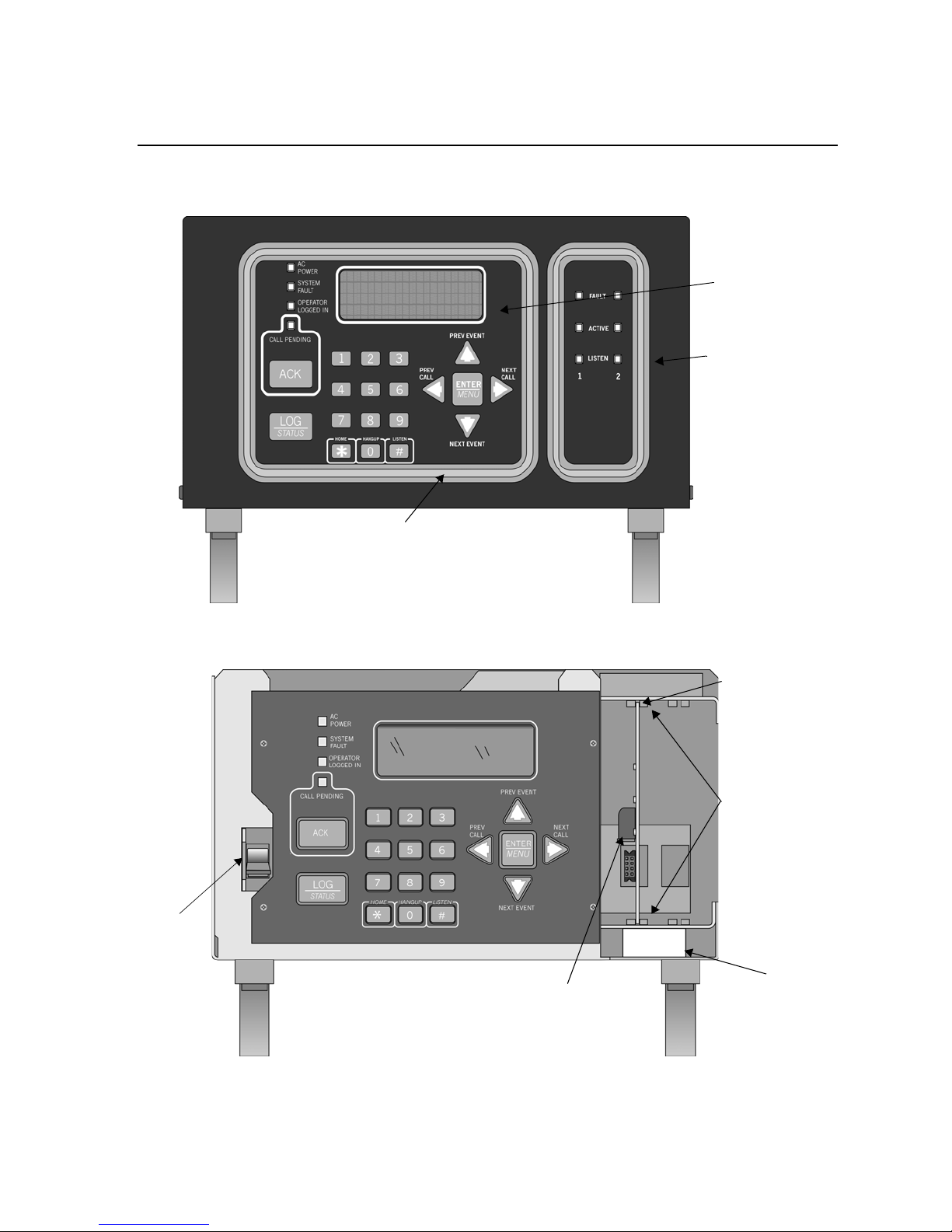
3.3 Overview
The 9500 is assembled at the factory . One line card is shipped with the 9500 receiver. Follow
the procedures described in Section 3.4 to install additional line cards.
LCD
Display
LED
Display
Main
Power Switch
Touchpad
Figure 3-1 Model 9500 Front View
Insert ed Line Car
Line Card Guides
Figure 3-2 Model 9500 Front View Without the Cover On
3-2 151059
Phone Line
Connector
Phone Lin e Slots
Installation
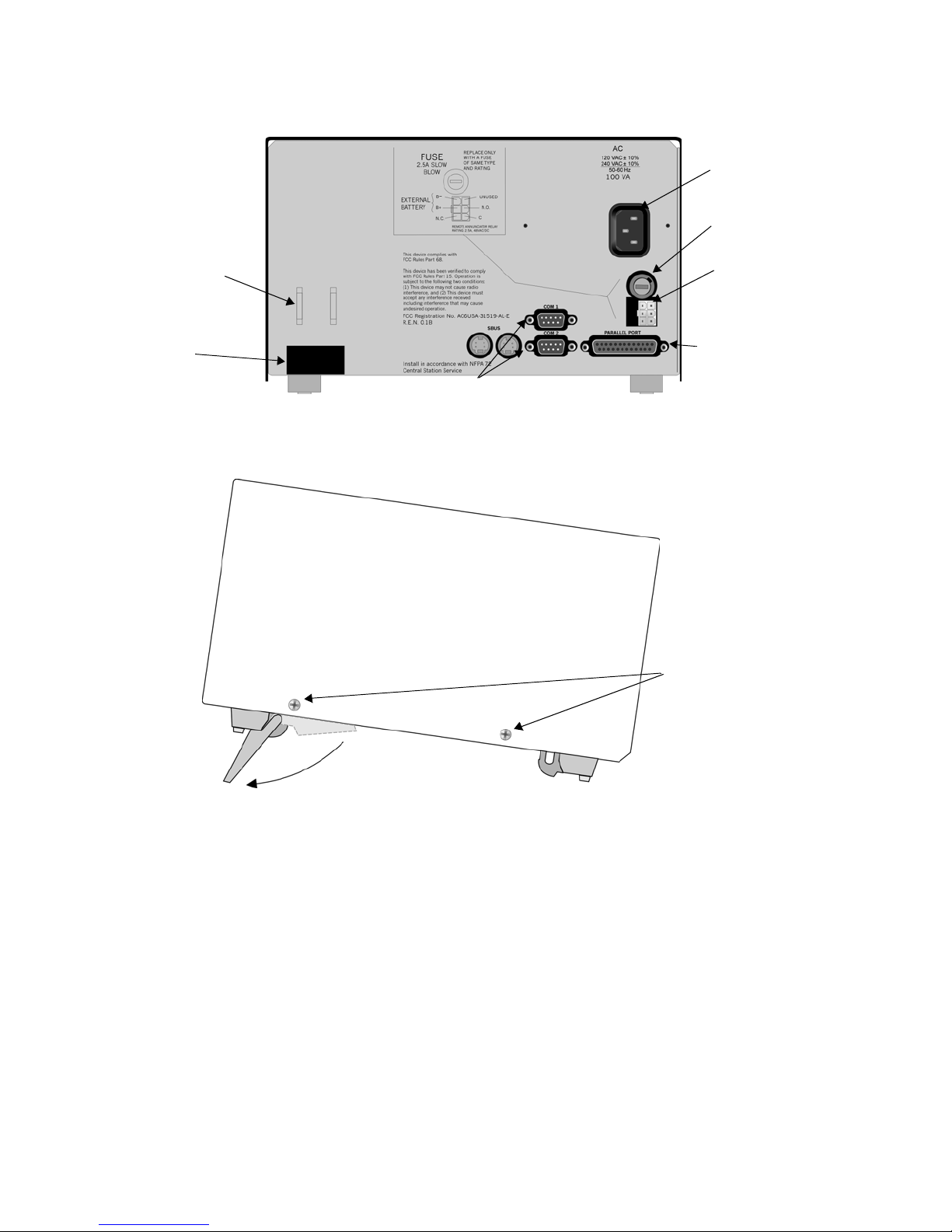
r
s
AC Power
Cord Connecto
Fuse
Phone Line
Strain Relief
Tie Wr ap Holders
Phone Line
Slot
Serial
Ports
Figure 3-3 Model 9500 Rear View
Remote Relay
Connector
Parallel
Printer Port
Cover Screw
(Two on each
side)
Flip Leg Down to
Raise Up Front
Figure 3-4 Side View
151059 3-3
Model 9500 Central Station R eceiver In stallation/Operation Manual
s
s
3.4 Line Card Installation
Caution:
To reduce the risk of electrical shock and damage to the receiver, follow these steps
in the order they are listed here.
1. Remove the 9500’s cover by unscrewing the four cover screws located on both sides of the
receiver. (See Figure 3-4 for the cover screw locations.)
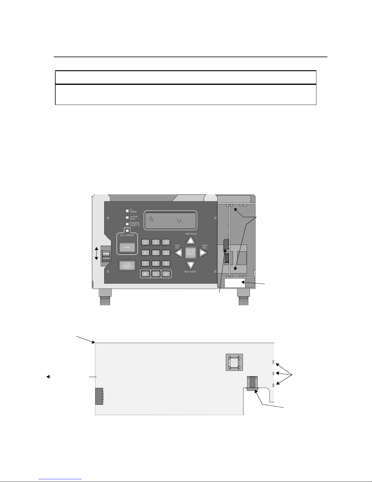
2. Tur n of f the 9500’s power switch (see Figure 3-5 for power switch location).
3. When the cover is removed, you will see that there are 2 slots for line cards. The receiver
recognizes each slot by number 1 and 2 (slot one is closest to the keypad and display). It is
not necessary to put line cards in numbered order because the receiver continually polls
each slot to see if existing line cards are functioning and if it is still in its slot. The receiver
also looks to see if a new line card has been added. Figure 3-5 shows where each line card
should be placed.
On
Power
Switch
Off
Figure 3-5 Line Card Locations
4. Position the line card as shown in Figure 3-6.
Top of Linecard
Insert From
Front of Receiver
In This Direction
Line Card
Guides
Phon e Line Slot
Phone Line
Connector
Line Card
Display LED
Figure 3-6 Line Card Position and Components
3-4 151059
Phon e Line
Connector

Installation
5. Carefully slide the card into its guides (both top and bottom) until it fits into its connector
at the back of the receiver. Gently push the card as far into the connector as you can. The
card is now in place. See Figure 3-5.
6. Connect telephone line. (See Section 3.6 for telephone line installation.)
Note: Use the tie wrap (P/N 120101 provided with each line card) on the tie wrap holder to add strain relief to
the telephone lines. See Figure 3-3.
7. Power up the 9500. See Section 3.8 and 3.9 for AC and battery connections.
8. Replace the 9500’s cover and screw in the cover screws to hold the cover in place. If you
are simply replacing a line card with another card of the same type and are using the same
format settings, your installation is now complete. If not continue to the next step.
9. Enter programming mode to select the appropriate handshake configuration. (Go to
Section 5.4 for programming procedure.)
3.5 Removing Line Cards
If you need to remove a card:
1. Remove the 9500’s cover by unscrewing the four cover screws located on both the sides of
the receiver. (See Figure 3-4 for front plate retaining screw locations.)
2. Tur n of f the 9500’s AC power switch (see Figure 3-2 for power switch location).
With the cover removed you will see that there are 2 slots for line cards.
3. Locate the Line Card that you wish to remove.
4. Unplug the telephone line. (See Figure 3-5 and Figure 3-6.)
5. From the front side of the receiver pull the line card straight back. This will pull the card
free from the connector at the rear of the receiver.
6. When the card is free, slide it carefully out of the receiver.
Note: If replacing a line card with a new one see Section 3.4 to install the new line card.
7. Power up the 9500.
8. Replace the 9500's cover and replace the cover screws.
9. Enter programming mode to clear the linecard from the system. (See Section 5.4 for
programming procedure.)
151059 3-5

Model 9500 Central Station R eceiver In stallation/Operation Manual
3.6 Telephone Line Connection
See Figure 3-3 for the location of the phone line inputs. Connections to the 9810 phone jacks
are made with a standard 7-foot phone cord (provided with each line card).
Use the following procedure to connect phone lines to the 9810 line cards:
1. Remove the cover of the 9500 receiver by loosening cover screws. (See Figure 3-4 for
cover screws locations.)
2. From the back side of the receiver insert the telephone line through the corresponding slot
for the desired line card. (See Figure 3-5 and Figure 3-6 for phone line slot locations.)
3. Gently push it all the way through to the front side of the receiver.
4. Plug the RJ-11 phone connector into the connector on the 9810 line card. (See Figure 3-5
and Figure 3-6.)
Note: Use the tie wrap (P/N 120101 provided with each line card) on the tie wrap holder to add strain relief to
the telephone lines. See Figure 3-3.
5. Replace the cover of the 9500 receiver. (See Figure 3-4 for cover screws locations.)
3-6 151059
Installation
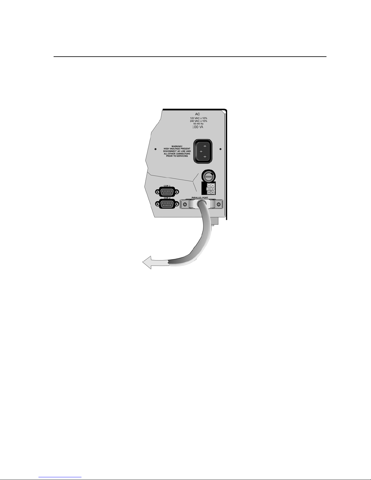
3.7 Parallel Printer Connection
The 9500 Receiver connects to model SK320 printer for UL applications. To connect the
SK320 to the 9500 receiver follow these steps:
1. Connect the standard parallel printer cable to the parallel printer port on the back of the
9500 receiver. (See Figure 3-7.)
To Printer
Figure 3-7 Parallel Printer Cable Connection to 9500
2. Connect the other end to the SK320 parallel printer port.
Note: Make sure that printer power is turned off.
3. Turn the printer power “on”.
151059 3-7

Model 9500 Central Station R eceiver In stallation/Operation Manual
3.7.1 Printer Cable Pin-Outs
25 pin printer cables are a standard items at most electronic stores, however, if you create your
own cable, use the pin description in Table 3-1.
Table 3-1: External Printer Cable Pin Description
9500 Pin # Signal Direction Description
1 Data Strobe (Low) Out A low strobe pulse to read data in the
pulse width is greater than 0.5
microseconds.
2 Data Bit 1 Out These signals rep resent information
3 Data Bit 2 Out
4 Data Bit 3 Out
5 Data Bit 4 Out
6 Data Bit 5 Out
7 Data Bit 6 Out
of the first to eighth bits of par allel
data. Each signal is at high level
when the data is logic 1 and low
when it is logic 0.
8 Data Bit 7 Out
9 Data Bit 8 Out
10 /AckNlg In A low pulse from the printer signals
the contro l tha t the pri nter is ready fo r
addi tiona l data.
11 Busy In A high level indicates that the printer
is busy.
12 Paper Empty In A high level indicates that the printer
is out of paper.
13 Select In A low level indicates the printer is
offline or in an error condition.
14 Not used - 15 Not used - 16 Logic ground - Logic ground for printer
17 Not used - 18 to 25 Logic Ground - Ground return for data lines.
3.7.2 Com Ports 1 & 2
Com ports one and two are serial communication ports that (through a null modem cable) can
be used to communicate to other serial communication devices. Com port one is the only
serial communications port that can be us ed with the automation computer (see Section 3.10).
A standard null modem cable can be used to connect com port 1 or 2 to another serial device
such as a printer or a PC. Figure 3-14 and Figure 3-15 shown the pin-outs for a null modem
cable. See Section 5.3.3 to configure the Com Port 1 and Com Port 2.
3-8 151059
Installation
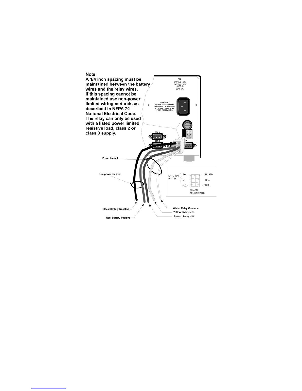
3.7.3 Remote Alert Output
1. Plug the Relay wiring harness onto the connector on the back of the 9500 receiver. (See
Figure 3-8.)
Note: The remote alert output is a form C relay with a nor mally open or a normally closed wire.
Figure 3-8 9500 Remote Alert Output/External Backup Battery Connection
2. Connect the white wire to common.
3. Use the Yellow wire for a normally closed circuit
Or
Use the Brown wire for a normally open circuit.
151059 3-9

Model 9500 Central Station R eceiver In stallation/Operation Manual
3.8 AC Power Cord Connection
3.8.1 Using Standard Power Cord
1. Before the AC power cord is connected, make sure that the power switch is in the OFF
(down) position. See Figure 3-2 and Figure 3-10.
2. Connect the appropriate end of the power cord into its receptacle on the back of the 9500.
3. Plug the three-pronged end of the power cord into a 120 VAC 60 Hz outlet (three-prong
type only). The outlet should be unswitched, so that power remains on 24 hours a day. The
outlet must also be earth grounded. Follow the directions in Section 3.8.4 if you need to
measure for proper earth grounding.
3.8.2 Using UL Listed AC Power Connectio n
To meet UL requirements for Central Station Service, the AC power must be run in conduit
into a single gang junction box. Use UL listed Model 9512 Conduit Connector Kit to attach
conduit to the receiver.
Table 3-2 lists the items contained in the 9512 Conduit Connector Kit.
Table 3-2: 9512 Conduit Connector Kit
Item Quantity
Single Gan g Electrical Box 1
Receiver Chassis Mounting Screw s 2
AC Pigtailed Power Cable 1
Follow these steps to properly connect the AC and the 9512 connector kit:
Note: It may be necessary to have a licensed el ectrician make the AC connect ions.
1. Run AC wire in conduit to the receiver.
Warning! To avoid electr ical shock, make sure that AC power on the this circuit is turne d off.
2. Feed AC wire through the conduit opening in the back (or the opening that best fits your
conduit configuration) of the single gang electrical box.
3-10 151059
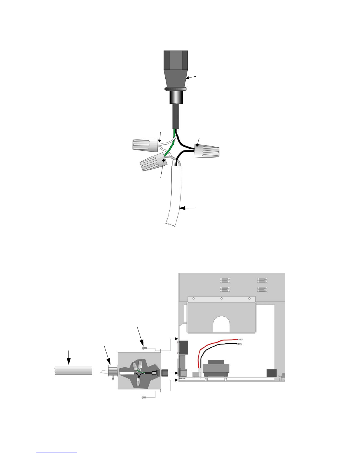
3. Connect the AC wire to the Receiver AC pigtailed power cable. See Figure 3-9.
le
Pigtailed
Power Cab
Return
(Neutral)
Wires
Ground
Wires
Line (Hot)
Wires
Installation
AC Wire
Figure 3-9 AC Wire Connection To Receiver Pigtail
4. Plug the wired pigtail into the AC receptacle on the back of the rece iver. See Figure 3-3.
5. Secure the electrical box to the back of the receiver with the two receiver chassis
mounting screws.
Conduit
Coupler
Conduit
Receiver
Chassis
Mounting
Screw
6. Connect the conduit to the electrical box using the appropriate conduit coupler.
7. Tur n on AC power to this circuit.
151059 3-11
Model 9500 Central Station R eceiver In stallation/Operation Manual
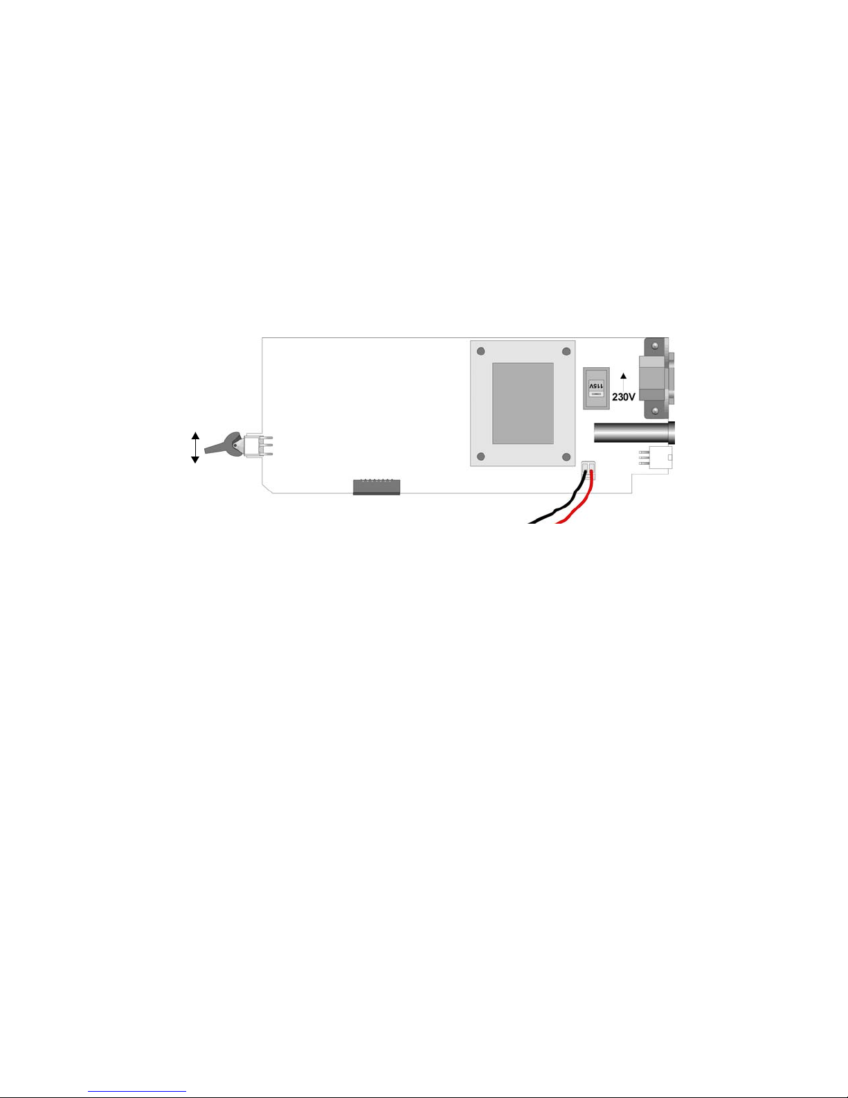
3.8.3 Switching to a 230 VAC Power Supply
1. Remove the cover by unscrewing the four cover screws. (See Figure 3-4 for locations of
cover sc re w s.)
2. Turn the main power switch to the “off” position. (See Figure 3-10.)
3. Disconnect AC power cable. See Sections 3.8.1 or 3.8.2 depending on the type of AC
connection used in this installation.
4. Disconnect the backup battery. (See Figure 3-13.)
5. Switch the power supply select switch to the up position. The switch will show 230VAC.
(See Figure 3-10 and Figure 3-12.)
On
Off
Figure 3-10 Side View of Power Supply Assembly
6. Reconnect the AC power cable.
Note: Make sure to plug the AC power cable into a grounded 240VAC outlet.
7. Reconnect the back-up battery. (See Figure 3-13.)
8. Tur n the main power switch to the “on” position. (See Figure 3-10.)
9. Replace the cover by screwing in the four cover screws. (See Figure 3-4.)
3-12 151059
Installation
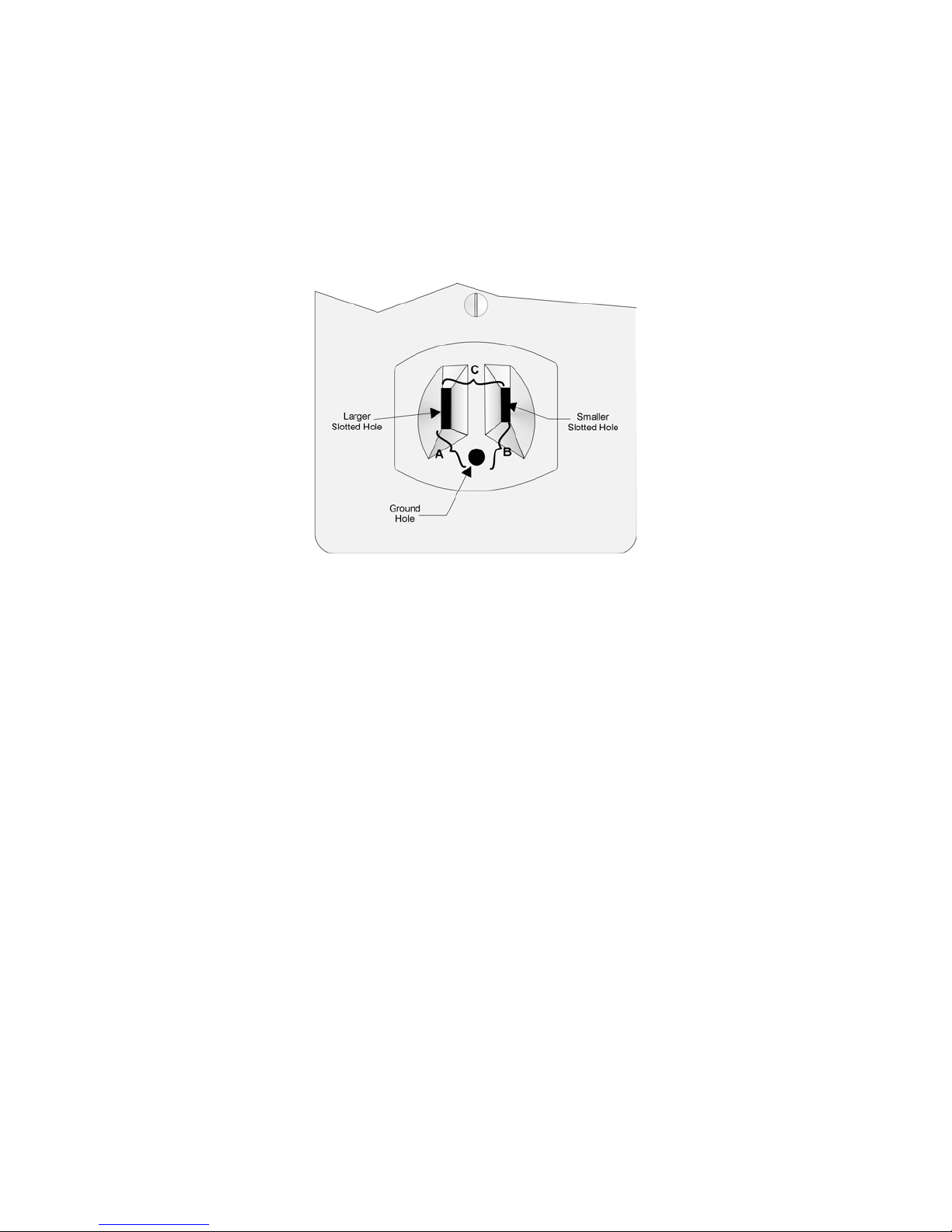
3.8.4 How to Verify Ea rth Ground
To verify earth ground at the AC outlet the 9500 receiver is powered from, use the following
steps:
1. Measure the AC voltage between the center ground post and each side of the outlet (see A
& B in Figure 3-11). You should read approximately 120 VAC (or 240VAC for 240VAC
circuits) at measurement point B and nominal VAC at measurement point A.
Figure 3-11 Outlet Voltage Measurement Points
2. Measure the voltage between the two slotted holes. It should be equal to the voltage
reading at measurement point B. (See Figure 3-11.)
If these voltages are not equal, the outlet does not have a proper earth ground.
3. Ground the outlet by running a wire (18 gauge or higher) to a good earth ground.
The wire should be of equal or greater diameter to the wires used to feed the outlet. It may be
necessary to have a licensed electrician ground the outlet.
151059 3-13
 Loading...