

Page 1

MODEL
5895XL
Intelligent Power Module
for the 5820XL System
Installation and
Operations Manual
ECN: 11-0317
Document 151142-L8
Rev:
151142-L8:J 15-0644
J
Page 2

Page 3

Content
Section 1
Overview ......................................................................................................................................................1-1
1.1 5895XL Description ..................................................................................................................1-1
1.1.1 Maximum Number of SBUS Modules ................................................................................1-2
1.2 Agency Requirements ..............................................................................................................1-5
1.3 About This Manual ...................................................................................................................1-5
1.4 How to Contact Silent Knight ....................................................................................................1-5
Section 2
Before You Begin Installing ......................................................................................2-1
2.1 What’s in the Box? ...................................................................................................................2-1
2.2 Environmental Specifications ............. ... ... .... ... .......................................... ...............................2-1
2.3 Preventing Water Damage .......................................................................................................2-1
2.4 5895XL Board and Terminal Strip Description .........................................................................2-2
2.5 Earth Fault Resistance .............................................................................................................2-4
2.6 Calculating Current Draw and Standby Battery ........................................................................2-5
2.6.1 Worksheet Requirements ..................................................................................................2-5
Filling in the Current Draw Worksheet, Table 2-4 (Section 2.6.2) ..................................2-5
2.6.1.1 Maximum Battery Standby Load .............................................................................. 2-5
2.6.2 Current Draw Worksheet ....................................... ... ... .... ... ... ... ... .... ... ...............................2-6
2.7 Wiring Specifications ................................................................................................................2-7
2.7.1 Length Limitations . .... ... ... ... ....................................... ... .... ... ... ... ... ......................................2-7
2.7.2 Calculating Wiring distance for SBUS modules .................. ............................................... 2-7
Wiring Distance calculation example: .............................................................................2-9
2.7.3 Wire Routing ....................................................................................................................2-10
Section 3
Hardware Installation .................................................................................................................. 3-1
3.1 AC Power ..................................................... ... ... ... ....................................... ... .... ... ... ...............3-1
3.2 Battery Connection ...................................................................................................................3-2
3.3 Connecting the 5895XL to the FACP .......................................................................................3-3
3.3.1 Setting the Device ID ......................... .... ... ... ....................................... ... ... .... .....................3-5
3.4 Connecting SBUS Modules to the 5895XL ..............................................................................3-6
3.5 Flexputs™ I/O Circuits .............................................................................................................3-7
3.5.1 Conventional Notification Appliance ..................................................................................3-7
3.5.2 Releasing Operations ......................................... ... ... ... .... ... ... ... ... .... ... ...............................3-7
3.5.2.1 Class B Notification Wiring .......................................................................................3-7
3.5.2.2 Class A Notification Wiring .......................................................................................3-8
3.5.3 Conventional Initiation Circuits ...........................................................................................3-9
3.5.3.1 ................................................................................................................................. 3-9
3.5.3.2 Class A Inputs ........................................... ... ... ... .... ... ... ... ... ......................................3-9
151142 i
Page 4

Model 5895XL Intelligent Power Module Installation and Operation Manual
3.5.4 Installing 2-Wire Smoke Detectors ............................ ....... ...... ...... ....... ...... ....... ...... ....... ...3-10
Class B Installation .......................................................................... ... ... .... ... ... ... ... .... ...3-10
2-Wire Class A Smoke Detector Installation .................................................................3-11
3.5.5 Installing 4-Wire Smoke Detectors ............................ ....... ...... ...... ....... ...... ....... ...... ....... ...3-12
Installing a Class B 4-Wire Smoke Detector .................................................................3-12
Installing 4-Wire Class A Smoke Detectors ..................................................................3-13
3.5.6 Auxiliary Power Configuration ..........................................................................................3-13
3.5.6.1 Door Holder Power .................................................................................................3-14
3.5.6.2 Constant Power ......................................................................................................3-14
3.5.6.3 Resettable Power ...................................................................................................3-14
3.6 Conventional Relay Installation ..............................................................................................3-14
Appendix A
Compatible Devices
A.1 Notification Appliances ............................................................................................................ A-1
A.2 Door Holder Device ............................................................................................................... A-12
A.3 Two-Wire Smoke Detectors ............................................................ ... .... ... ... ... .... ... ... ... ... ...... A-12
A.4 Four-Wire Smoke Detectors ..................................................................................................A-15
..................................................................................................................... A-1
Silent Knight Fire Product Warranty and Return Policy
Manufacturer Warranties and Limitation of Liability
ii 151142
Page 5

Section 1
Overview
1.1 5895XL Description
The Model 5895XL Intelligent Power Module provides additional power and circuits to
the IntelliKnight 5820XL F A CPs. The 5895XL can power all IntelliKnight compatible
modules, including SLC devices (via a Model 5815XL SLC Expander), remote
annunciators (Model 5860); notification appliances, auxiliary power modules, and all
other compatible modules.
Note: The 5808 does not use 5815XL SLC expanders.
The 5895XL has six Flexputs™ and two programmable relays. Outputs are rated 3.0
A (6.0 A total for each 5895XL). Relays are Form C rated at 2.5 A @ 24 VDC.
Outputs and relays are fully programmable.
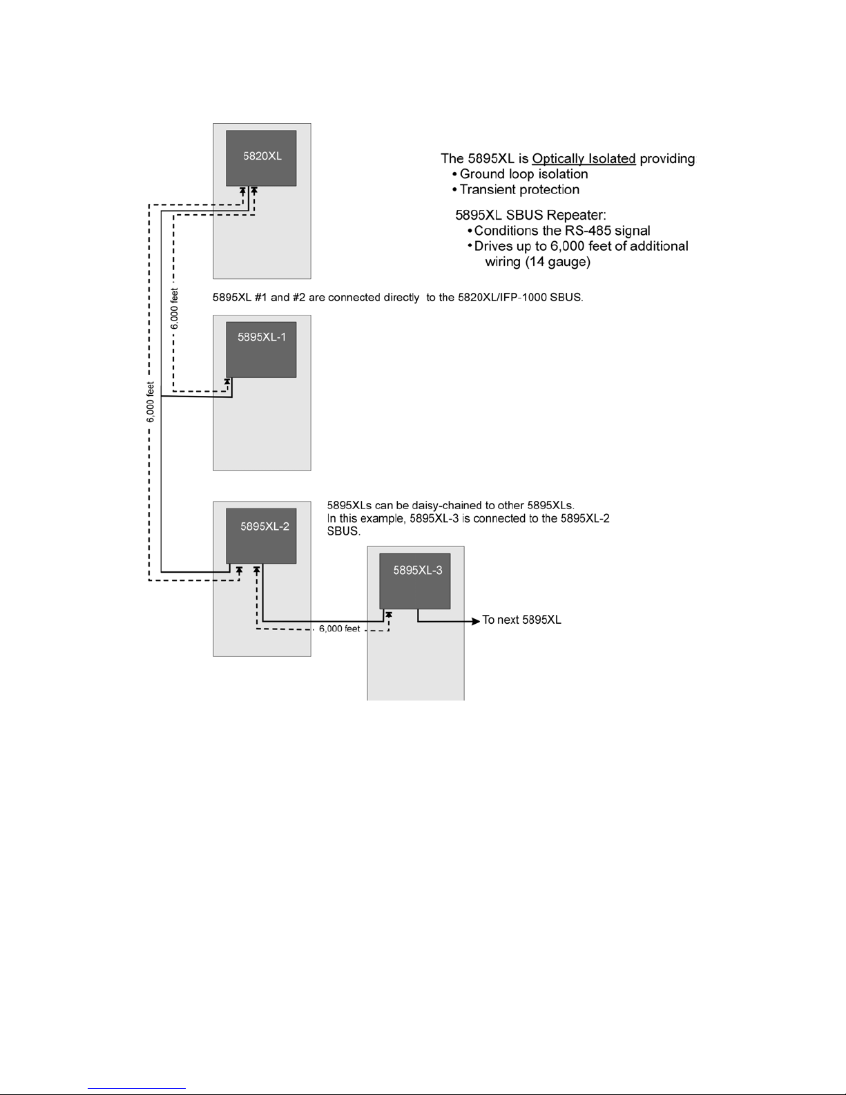
The 5895XL is optically isolated, providing ground loop isolation and transient
protection. It functions as an SBUS repeater which conditions the RS-485 signal and
allows the module to drive up to 6,000 feet of additional SBUS wiring.
The 5895XL is housed in a metal cabinet that is identical in size to the IntelliKnight
5820XL FACP cabinet. This cabinet is large enough to house two 17 AH batteries.
Like the 5820XL cabinets, the 5895XL cabinet provides mounting studs for two Model
5815XL SLC Expander modules.
The 5895XL communicates to the main IntelliKnight FACP via the SBUS. Each
5895XL provides an additional 6,000 feet of SBUS wiring length to the main panel. As
the drawings on the next pages illustrate, this allows you to distribute modules, SLC
devices, and outputs throughout an extremely large facility.
As well as expanding the wiring length capabilities of IntelliKnight, the 5895XL also
expands IntelliKnight’s power capabilities by an additional 6.0 A of current.
151142 1-1
Page 6

Model 5895XL Intelligent Power Module Installation and Operation Manual
1.1.1 Maximum Number of SBUS Modules
The chart below shows the maximum number of compatible modules that can be
used in an IntelliKnight installation. Modules can be distributed among the main panel
SBUS and each additional 5895XL SBUS in virtually any combination.
Module or Device Maximum Number
5895XL Intelligent Power Module 8 per IntelliKnight installation
5860 Remote Annunciator 8 per IntelliKnight installation
5815XL SLC Expander 2 per IntelliKnight installation
5824 Serial/Parallel Modules 8 per IntelliKnight installation
Outputs 6 per 5820XL / 5895XL
Conventional Relays 2 per 5820XL / 5895XL
1-2 151142
Page 7
Overview
Figure 1-1 Example 5895XL Installation Overview
151142 1-3
Page 8
Model 5895XL Intelligent Power Module Installation and Operation Manual
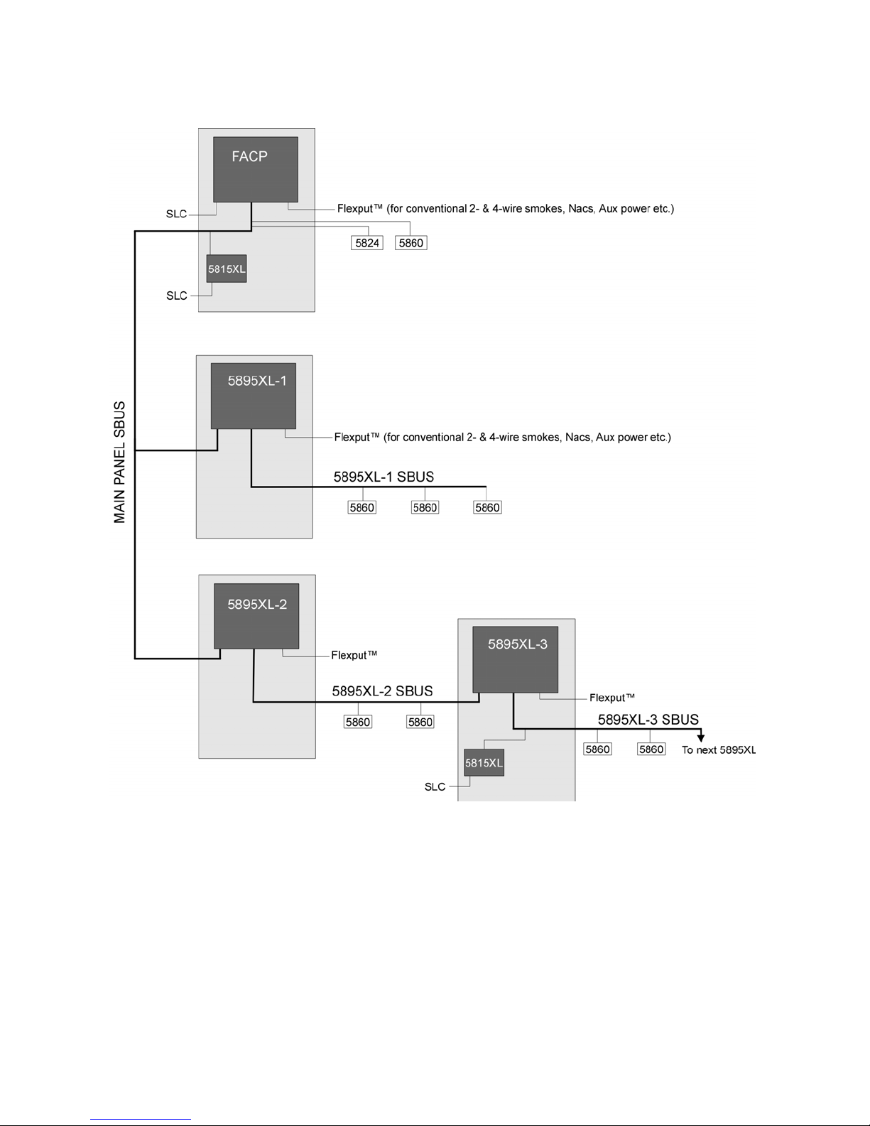
Figure 1-2 Example 5895XL Installation Overview (Details Added)
1-4 151142
Page 9

Overview
1.2 Agency Requirements
The 5895XL has the same requirements as the main control panel. These
requirements are listed in the IntelliKnight 5820XL Installation Manual (P/N 151209).
1.3 About This Manual
This manual covers installation of 5895XL hardware. Software configuration
information is contained in the IntelliKnight 5820XL Installation Manual (P/N 151209).
1.4 How to Contact Silent Knight
If you have a question or encounter a problem not covered in this manual, contact
Silent Knight Technical Support at 800-446-6444.
To order parts, contact Silent Knight Sales at 800-328-0103 (or 203-484-7161).
151142 1-5
Page 10

Section 2
Before You Begin Installing
2.1 What’s in the Box?
The Model 5895XL ships with the following hardware:
• A cabinet with all hardware assembled
• Two keys for the front door
• Ten 4.7K ohm end-of-line resistors
Note: For UL installations Model 7628 4.7k end-of-line resistor (ordered separately) must be used.
• A battery cable for batteries wired in series
2.2 Environmental Specifications
It is important to protect the 5895XL control panel from water. To prevent water
damage, the following precautions should be FOLLOWED when installing the units:
• Do not mount directly on exterior walls, especially masonry walls (condensation)
• Do not mount directly on exterior walls below grade (condensation)
• Protect from plumbing leaks
• Protect from splash caused by sprinkler system inspection ports
• Do not mount in areas with humidity-generating equipment (such as dryers, production machinery)
When selecting a location to mount the 5895XL, the unit should be mounted where it
will NOT be exposed to temperatures outside the range of 0°C-49°C (32°F-120°F) or
humidity outside the range of 10%-93% at 30°C (86°F) non-condensing.
2.3 Preventing Water Damage
Water damage to the fire system can be caused by moisture entering the cabinet
through the conduits. Conduits that are installed to enter the top of the cabinet are
most likely to cause water problems. Installers should take reasonable precautions to
prevent water from entering the cabinet. Water damage is not covered under
warranty.
151142 2-1
Page 11
Model 5895XL Intelligent Power Module Installation and Operation Manual
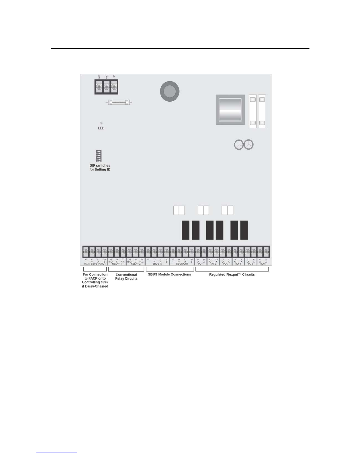
2.4 5895XL Board and Terminal Strip Description
Figure 2-1 shows the 5895XL circuit board including location of terminals, the DIP
switch for setting module ID, and the LED.
2-2 151142
Figure 2-1 The 5895XL Board Layout
Page 12

Before You Begin Installing
Table 2-1: Terminal Strip Description and Electrical Ratings
Terminal # and Label
1 L AC input (hot)
2 G Earth ground N/A N/A
3 N AC input (neutral)
4X
5 O 100 mA Initiation Circuits
6 X
7 O 100 mA Initiation Circuits
8X
9O
10 X
11 O 100 mA Initiation Circuits
12 X
13 O 100 mA Initiation Circuits
14 X
15 O 100 mA Initiation Circuits
16 B
17 A
18 +
19 20 B
21 A
22 +
23 24 N.C.
26 N.O.
27 N.C.
29 N.O.
30 B
31 A
32 +
33 -
I/O 6* Flexput™ Circuit 24 VDC
I/O 5* Flexput™ Circuit 24 VDC
I/O 4* Flexput™ Circuit 24 VDC
I/O 3* Flexput™ Circuit 24 VDC
I/O 2* Flexput™ Circuit 24 VDC
I/O 1* Flexput™ Circuit 24 VDC
SBUS communication 5 VDC 100 mA
SBUS OUT
SBUS power 24 VDC 1.0 A
SBUS IN Used for Class A installations
RELAY 2 G eneral Purpose Relay 2 24 VDC 2.5 A25 C
RELAY 1 General Purpose Relay 1 24 VDC 2.5 A28 C
SBUS IN/
OUT
MAIN
5895XL communication with
main panel or to controlling
5895XL if daisy-chained
5895XL SBUS power (from
5820XL)
Description
Voltage Current
120/240 VAC,
50/60 Hz
120/240 VAC,
50/60 Hz
5 VDC 100 mA
24 VDC 10 mA
Rating
2.7 A
1.4 A
2.7 A
1.4 A
3.0 A Notification Circuits
3.0 A Notification Circuits
3.0 A Notification Circuits
100 mA
Initiation Circuits
3.0 A Notification Circuits
3.0 A Notification Circuits
3.0 A Notification Circuits
* Regulated/special application when used for releasing.
151142 2-3
Page 13

Model 5895XL Intelligent Power Module Installation and Operation Manual
2.5 Earth Fault Resistance
Table 2-2 lists the earth fault resistance detection for each applicable terminal on the
FACP .
Table 2-2: Earth Fault Resistance Values by Terminal
Terminal Label Low Biased High Biased
Function
Terminal
Number
(Values in kohms)
High
Trip
High
Restore
Low
Trip
Low
Restore
Flexput™
Notification
Circuits
SBUS
Communication
SBUS Power
4X
5O 00-6X
7O 00-8X
9O 00-10 X
11 O 0 0 - 12 X
13 O 0 0 - 14 X
15 O 0 0 - 16 B
17 A - - 0 0
18 + 0 0 - 19 - - - 0 0
I/O 6
I/O 5
I/O 4
I/O 3
I/O 2
I/O 1
SBUS
OUT
--00
--00
--00
--00
--00
--00
--00
20 B
Used for Class
A Installations
21 A - - 0 0
22 + 0 0 - 23 - - - 0 0
2-4 151142
--00
SBUS IN
Page 14

Before You Begin Installing
2.6 Calculating Current Draw and Standby Battery
This section is for helping you determine the current draw and standby battery needs
for your installation.
2.6.1 Worksheet Requirements
The following steps must be taken when determining 5895XL current draw and
standby battery requirements.
Filling in the Current Draw Worksheet, Table 2-4 (Section 2.6.2)
1. For the 5895XL, the worst case current draw is listed for the panel, addressable
devices, and SLC expanders. Fill in the number of addressable devices and
expanders that will be used in the system and compute the current draw requirements for alarm and standby. Record this information in Table 2-4 at Line A.
2. Add up the current draw for all auxiliary devices and record in the table at Line B.
3. Add up all notification appliance loads and record in the table at Line C.
4. For notification appliances and auxiliary devices not mentioned in the manual,
refer to the device manual for the current ratings.
5. Make sure that the total alarm current you calculated, including current for the
panel itself, does not exceed 6.0 A. This is the maximum alarm current allowable.
6. Complete the remaining instructions in Table 2-4 for determining battery size
requirements.
2.6.1.1 Maximum Battery Standby Load
Table 2-3 shows the maximum battery standby load for the 5895XL based on 24 and
60 hours of standby. The standby load calculations of line G in the Current Draw
Calculation Worksheet (Table 2-4) must be less than the number shown in Table 2-3
for the battery size used and standby hours required.
Table 2-3: Maximum Battery Standby Load
Rechargeable
Battery Size
7 AH 270 mA 105 mA
12 AH 475 mA 190 mA
17 AH 685 mA 270 mA
33 AH 1370 mA 540 mA
* Required for NFP A 72 Auxiliary Protected Fire Alarm systems for Fire Alarm Service (City Box)
and Remote Station Protected Fire Alarm systems (Polarity Reversal) and Digital Alarm Communicator/Transmitter (DACT).
Max. Load for 24 hrs. Standby ,
5 mins. Alarm
*Max. Load for 60 hrs. Standby , 5
mins. Alarm
Note:33AH max battery size for FM (Factory Mutual) installations
151142 2-5
Page 15

Model 5895XL Intelligent Power Module Installation and Operation Manual
2.6.2 Current Draw Worksheet
For *each 5895XL in the installation, use this worksheet to determine current
requirements during alarm/battery standby operation. (Copy this page if additional
space is required.)
Table 2-4: Current Draw Calculations
Device
For each device use this formula: This column X This column = Current per number of
devices.
5895XL Intelligent Power Module
(Current draw from battery)
Additional 5895XL
(Daisy-chained to this module)
Addressable Devices (381 max.)
5815XL SLC Expander (2 max.)
5860 Remote Fire Alarm Annunciator (8 max.)
5824 Serial / Parallel Module (2 max.)
5865-4 LED Annunciator
(with reset and silence switches)
5865-3 LED Annunciator
5880 Generic LED Driver Module
A Total System Current
**Auxiliary Devices Refer to devices manual for current rating.
B Auxiliary Devices Current
C Notification Appliances Current mA
D Total current ratings of all devices in system (line A + line B + C) mA mA
E Total current ratings converted to amperes (line D x .001): A A
F Number of standby hours (24 or 60 for NFPA 72, chapter 1, 1-5.2.5 ) : H
G Multiply lines E and F. Total standby AH AH
H Alarm sounding period in hours. (For example, 5 minutes = .0833 hours) H
I Multiply lines E and H. Total alarm AH
J ***Add lines G and I. Total ampere hours required AH
Number of
Devices
1*
(7 max.)
(8 max.)
Current per Device
Standby: 40 mA
Alarm: 160 mA
Standby: 10 mA
Alarm: 10 mA
Standby: 0.55 mA
Alarm: 0.55 mA
Standby: 55 mA mA
Alarm: 55 mA mA
Standby: 20 mA mA
Alarm: 25 mA mA
Standby: 45 mA mA
Alarm: 45 mA mA
Standby: 35 mA mA
Alarm: 145 mA mA
Standby: 35 mA mA
Alarm: 145 mA mA
Standby: 35 mA mA
Alarm: 200 mA mA
Alarm/Standby: mA mA mA
Alarm/Standby: mA mA mA
Alarm/Standby: mA mA mA
Alarm/Standby: mA mA mA
Alarm: mA
Alarm: mA mA
Alarm: mA
Alarm: mA
Standby
Current
40
mA
Alarm Current
160
mA
mA
mA
mA
AH
2-6 151142
Page 16

Before You Begin Installing
* Use a separate worksheet for each 5895XL.
** If you are using door holders, you do not need to consider door holder current for alarm/battery standby, because
*** Use next size battery with capacity greater than required.
power is removed during that time. However, during normal operation, door holders draw current and must be
included in the 6.0 A total current that can be drawn from the panel.
2.7 Wiring Specifications
2.7.1 Length Limitations
This section contains information on calculating SBUS wire distances and the types
of wiring configurations (Class A and B).
2.7.2 Calculating Wiring distance for SBUS modules
The following instructions will guide you in determining the type of wire and the
maximum wiring distance that can be used with SBUS accessory modules.
To calculate the wire gauge that must be used to connect SBUS modules to the
panel, it is necessary to calculate the total worst case current draw for all modules on
a single 4-conductor bus. The total worst case current draw is calculated by adding
the individual worst case currents for each module. The individual worst case values
are shown in the table below.
Note: Total worst case current draw on a single SBUS cannot exceed 1 amp. If a large number of
accessory modules are required, and the worst case current draw will exceed the 1 amp limit,
then the current draw must be distributed using 5895XL Powe r Expanders. Each 5895XL Power
Expander provides an additional SBUS, with an additional 1 amp of SBUS current. Wiring
distance calculations are done separately for each 5895XL, and separately for the panel itself.
Model Number Worst Case Current Draw
5860 Fire Annunciator .100 amps
5824 Parallel/Serial Interface .040 amps
5880 LED IO Expander .250 amps
5865 LED Fire Annunciator .200 amps
5895XL Intelligent Power Supply .010 amps
5496 Intelligent Power Module .010 amps
After calculating the total worst case current draw, Table 2-5 specifies the maximum
distance the modules can be located from the panel on a single wire run. The table
insures 6.0 volts of line drop maximum. In general, the wire length is limited by
resistance, but for heavier wire gauges, capacitance is the limiting factor.
151142 2-7
Page 17

Model 5895XL Intelligent Power Module Installation and Operation Manual
These cases are marked in the chart with an asterisk (*). Maximum length can never
be more than 6,000 feet, regardless of gauge used. (The formula used to generate
this chart is shown in the note below).
Table 2-5: Wire Distances Per Wire Gauge
Wiring Distance: SBUS Modules to Panel
Total Worst Case
Current Draw (amps)
0.100 1852 ft. 4688 ft. * 6000 ft. * 6000 ft.
0.200 926 ft. 2344 ft. 3731 ft. 5906 ft.
0.300 617 ft. 1563 ft. 2488 ft. 3937 ft.
0.400 463 ft. 1172 ft. 1866 ft. 2953 ft.
0.500 370 ft. 938 ft. 1493 ft. 2362 ft.
0.600 309 ft. 781 ft. 1244 ft. 1969 ft.
0.700 265 ft. 670 ft. 1066 ft. 1687 ft.
0.800 231 ft. 586 ft. 933 ft. 1476 ft.
0.900 206 ft. 521 ft. 829 ft. 1312 ft.
1.000 (Max) 185 ft. 469 ft. 746 ft. 1181 ft.
22 Gauge 18 Gauge 16 Gauge 14 Gauge
Note: The following formulas were used to generate the wire distance chart:
Maximum Resistance (Ohms) =
Maximum Wire Length (Feet) =
(6000 feet maximum)
where: Rpu = Ohms per 1000 feet for various Wire Gauges (see table below)
Total Worst Case Current Draw (amps)
Maximum Resistance (Ohms)
6.0 Volts
Rpu
* 500
Table 2-6: Typical Wire Resistance Per 1000 ft.
Wire Gauge Ohms per 1000 feet (Rpu)
22 16.2
18 6.4
16 4.02
14 2.54
2-8 151142
Page 18

Before You Begin Installing
Wiring Distance calculation example:
Suppose a system is configured with the following SBUS modules:
2 - Module 5860 Fire Annunciator
1 - 5895XL Intelligent Power Expander
1 - 5865 LED Fire Annunciator
1 - 5824 Parallel/Serial Interface
The total worst case current is calculated as follows:
5860 Current Draw = 2 x .100 amps = .200 amps
5895XL Current Draw = 1 x .010 amps = .010 amps
5865 Current Draw = 1 x .200 amps = .200 amps
5824 Current Draw = 1 x .040 amps = .040 amps
Total Worst Case Current Draw = .450 amps
Using this value, and referring to the Wiring Distance table, it can be found that the
available options are:
370 feet maximum using 22 Gauge wire
938 feet maximum using 18 Gauge wire
1493 feet maximum using 16 Gauge wire
2362 feet maximum using 14 Gauge wire
151142 2-9
Page 19

Model 5895XL Intelligent Power Module Installation and Operation Manual
5895XL Board
2.7.3 Wire Routing
You must follow power-limited wiring techniques, which includes maintaining
one-quarter inch spacing between power-limited and nonpower-limited circuits and
separating high and low voltage circuits.
Figure 2-2 Wire Routing Example
2-10 151142
Page 20

Section 3
To 120 VAC
Power Source
Green
White
Black
Hardware Installation
5895XL installation involves the following steps:
• AC power (Section 3.1) and backup battery connection (Section 3.2).
• Physical connection to the IntelliKnight 5820XL FA CP or to the controlling 5895XL
(see Section 3.3).
• Setting an ID for the 5895XL (Section 3.3.1).
• Physical connection of SBUS modules t hat will be powered by this 5895XL
(Section 3.4).
• Physical connection of any outputs (conventional relays, notification appliances,
auxiliary power modules, and so on) that will be powered by this 5895XL. See
Section 3.5.1 for notification appliance wiring information. Refer to the IntelliKnight
5820XL Installation Manual (P/N 151209), for software configuration information
and other information about installing outputs.
3.1 AC Power
At installation, connect the AC terminals to 120 VAC source as shown in Figure 3-1. It
may be necessary for a professional electrician to make this connection.
The AC terminals are rated as 120 VAC, 50 or 60 Hz, 2.7 A.
Figure 3-1 AC Power Connection
151142 3-1
Page 21

Model 5895XL Intelligent Power Module Installation and Operation Manual
Red
To Panel
Black
UL Listed 12V Battery
UL Listed 12V Battery
Battery Jumper
(P/N 140694)
Shipped With 5895XL
Replace batteries every 5 years.
Gell Cell
Gell Cell
3.2 Battery Connection
The 5895XL battery charge capacity is 7.0 to 33.0 AH. Use 12V batteries of the same
AH rating. Determine the correct AH rating as per your current load calculation (see
Section Table 2-4).
Note: When your backup batteries requirements use backup batteries that are to large to fit into the
5895XL cabinet. The AB-33 cabinet holds batteries up to the 33 AH size. (Refer to Installation
Manual P/N 151209 for AB-33 installation instructions.
* 33AH max battery size for FM (Factory Mutual) installations
Wire batteries in series to produce a 24-volt equivalent. Do not parallel batteries to
increase the AH rating.
3-2 151142
Figure 3-2 Battery Connection
Page 22

Hardware Installation
(FACP SBUS)
5895XL Terminals 30-33 are used only for
connection 5895XL to the FACP or to the
controlling 5895XL. Use 5895XL Terminals 16-19
to connect other SBUS modules (5815XL, 5860,
5824) and to daisy-chain 5895XL’s
5895XL Board
(5895XL-1)
5895XL Board
(5895XL-2)
To next 5895XL
and other SBUS
modules.
3.3 Connecting the 5895XL to the FACP
1. Connect the 5895XL to the appropriate SBUS. The 5895XL can be connected
directly to the IntelliKnight 5820XL FACP or can be daisy-chained to another
5895XL. Figure 3-3 and Figure 3-4 show both connections.
2. Use on-board DIP switch to assign an ID#. (See Section 3.3.1) Figure 2-1 shows
the location of the DIP switches on the 5895XL board.
3. Configure the 5895XL module by adding it to the system (through JumpStart or
manually). You can also assign a name to the module. These procedures are
described in the IntelliKnight 5820XL Installation Manuals (P/N 151209).
Figure 3-3 Class B 5895XL Connection to FACP
151142 3-3
Page 23

Model 5895XL Intelligent Power Module Installation and Operation Manual
See Figure 3-6 for SBUS Module Connections
See Figure 3-6 for
SBUS Module
Connections
Figure 3-4 Class A 5895XL Connection to FACP
3-4 151142
Page 24

Hardware Installation
3.3.1 Setting the Device ID
board to set the module ID#. Figure 2-1 shows the location of the DIP switch on the
board.
151142 3-5
Figure 3-5 Possible Module Addresses
Page 25

Model 5895XL Intelligent Power Module Installation and Operation Manual
3.4 Connecting SBUS Modules to the 5895XL
1. Connect SBUS modules to the 5895XL as shown in Figure 3-6 or Figure 3-7.
2. All SBUS modules must have an ID. Use the DIP switches on the module board to
assign an ID number (1-31) to the module. This number identifies the module to
the 5895XL and must be unique.
3. Software configuration steps vary for each SBUS module. For more information,
refer to the Installation Manual (P/N 151209) in the section that discusses the type
of module you are installing.
Figure 3-6 SBUS Class A Connection to 5895XL
3-6 151142
Page 26

Hardware Installation
Figure 3-7 SBUS Class B Wiring to 5895XL
3.5 Flexputs
The six Flexput™ circuits are an innovative and versatile feature of the 5895XL panel.
They can be used as: Class A or B notification circuits, Class A or B initiation circuits
(either 2 or 4 wire detectors), or as auxiliary power (resettable, continuous, or door
holder).
This section of the manual explains how to install conventional notification appliances
and initiating devices to be used with the 5895XL.
™
I/O Circuits
3.5.1 Conventional Notification Appliance
This sub-section of the manual explains how to install conventional notification
appliances for Class A (Style Z) and Class B (Style Y) configurations.
3.5.2 Releasing Operations
Approved releasing solenoids are list in Table 3-1. Do not mix cross alarming zones
with smoke verification zones. There must be at least two automatic detection
devices in each protected space. Spacing must be reduced to 0.7 times the linear
151142 3-7
Page 27

Model 5895XL Intelligent Power Module Installation and Operation Manual
Alarm
Polarity
UL Listed EOL
Model 7628
4.7 k
Supervised
Power Limited
Notification Wiring
Regulated
spacing in accordance with NFPA 72.
Table 3-1: Approved Releasing Solenoids
Manufacturer Part Number Rating Current Freq
Asco T8210A107 24 VDC 3A max 0 Hz
8210G207 24 VDC 3A max 0 Hz
3.5.2.1 Class B Notification Wiring
You must use an appliance from the list of compatible appliances in the Appendix A.
To install a Class B notification appliance circuit:
1. Wire Class B Notification appliances as shown in Figure 3-8.
2. Configure the circuit through programming.
Figure 3-8 Class B Notification Appliance Circuit Wiring
3-8 151142
Page 28

Hardware Installation
Regulated
3.5.2.2 Class A Notification Wiring
Y ou must use an appliance from the list of comp atible appliances in the Appendix A at
the back of this manual.
To install a Class A notification appliance circuit:
1. Wire the Class A notification appliances as shown in Figure 3-9.
2. Configure the circuit for Class A in programming (see Section 7.4 of the
Installation Manual P/N 151209).
Figure 3-9 Class A Notification Appliance Circuit Configuration
Note: In programming any point that uses multiple I/O circuits are always referred to as the lowest I/O
circuit number used. For example, Figure 3-9 uses both I/O circuit 5 and 6, so in programming it
would be referred to as point 5.
151142 3-9
Page 29

Model 5895XL Intelligent Power Module Installation and Operation Manual
UL Listed EOL
Model 7628
4.7 k
3.5.3 Conventional Initiation Circuits
This section of the manual explains how to install conventional initiating devices for
Class A (Style D) or Class B (Style B) configurations.
3.5.3.1 Class B Inputs
You can connect conventional Class B switches, such as waterflow switches and pull
stations, directly to the I/O circuits of the 5895XL panel.
To install a Class B switch:
1. Wire the Class B switch as shown in Figure 3-10.
2. Configure the circuit through programming (see Section 7.4 of the Installation
Manual P/N 151209).
Figure 3-10 Class B Input Switches
3.5.3.2 Class A Inputs
You can connect conventional Class A switches, such as waterflow switches and pull
stations, directly to the I/O circuits of the 5895XL panel.
To install a Class A switch:
1. Wire the Class A switch as shown in Figure 3-11.
3-10 151142
Page 30

Hardware Installation
Note:
I/O circuit 5 and 6
used as an example.
Any I/O point pairing
could be used.
2. Configure the circuit through programming (see Section 7.4 of the Installation
Manual
151209).
Figure 3-11 Class A initiating Switches
Note: In programming any point that uses multiple I/O circuits are always referred to as the lowest I/O
circuit number used. For example, Figure 3-11 uses both I/O circuit 5 and 6, so in programming
it would be referred to as point 5.
3.5.4 Installing 2-Wire Smoke Detectors
Any compatible U.L. listed two-wire smoke detector can be used with the 5895XL
panel (see Appendix A for list of compatible smoke detectors). Figure 3-12 and Figure
3-13 illustrate how to connect a UL listed 2-wire detector to the control panel.
151142 3-11
Page 31

Model 5895XL Intelligent Power Module Installation and Operation Manual
Note:
I/O circuit 5
used as an example.
Any I/O circuit
could be used.
UL Listed EOL
Model 7628
4.7 k
Note:
I/O circuit 5 and 6
used as an example.
Any I/O point pairing
could be used.
Class B Installation
To install a Class B two-wire smoke detector, wire as shown in Figure 3-12.
Figure 3-12 Two-Wire Class B Smoke Detector
2-Wire Class A Smoke Detector Installation
To install a Class A two-wire smoke detector, wire as shown in Figure 3-13.
Figure 3-13 Two-Wire Class A Smoke Detector Connections
Note: In programming any point that uses multiple I/O circuits are always referred to as the lowest I/O
circuit number used. For example, Figure 3-13 uses both I/O circuit 5 and 6, so in programming
it would be referred to as point 5.
3-12 151142
Page 32

Hardware Installation
Air Products
PAM-2
Model 160150
Supervision
Module
UL Listed
EOL Resistor
Model 7628
ESL 449CT
Note:
I/O circuit 5 and 6
used as an example.
Any I/O point pairing
could be used.
3.5.5 Installing 4-Wire Smoke Detectors
Any compatible U.L. listed four-wire smoke detector can be used with the 5895XL
panel (see Appendix A for list of compatible smoke detectors). Figure 3-12 and Figure
3-13 illustrate how to connect a UL listed four-wire detector to the control panel.
Installing a Class B 4-Wire Smoke Detector
Figure 3-14 illustrates how to install a 4-wire Class B smoke detector.
Conventions used for wiring 4-wire Class B loops:
1. Up to three Class B 4-wire smoke detector loops can be connected to the control
panel at once.
2. Each Class B loop input is paired with a unique power source as shown in Figure
3-14.
3. Each loop gets smoke power from the even numbered I/O circuit and the contact
input is connected to the odd numbered I/O circuit.
Figure 3-14 Class B 4-Wire Smoke Detector Connections
Note: In programming any point that uses multiple I/O circuits are always referred to as the lowest I/O
circuit number used. For example, Figure 3-14 uses both I/O circuit 5 and 6, so in programming
it would be referred to as point 5.
151142 3-13
Page 33

Model 5895XL Intelligent Power Module Installation and Operation Manual
Air Products
PAM-2
Model 160150
Supervision
Module
Air Products
PAM-2
Model 160150
Supervision
Module
Installing 4-Wire Class A Smoke Detectors
Figure 3-15 illustrates how to install 4-wire Class A detectors.
Conventions used for wiring 4-wire Class A loops:
1. Up to two Class A 4-wire loops can be connected to the control panel at once.
2. Smoke power is supplied to each Class A loop as shown in Figure 3-15.
Figure 3-15 Class A 4-Wire Smoke Detector Connections
Note: In programming any point that uses multiple I/O circuits are always referred to as the lowest I/O
circuit number used. For example, Figure 3-15 uses I/O circuits 1, 2, 3 together and 4, 5, 6
together. In programming (1, 2, 3) would be referred to as point 1, and (4, 5, 6) would be referred
to as point 4.
3.5.6 Auxiliary Power Configuration
Flexput circuits 1-6 on the control panel can be used as auxiliary power circuits. The
three types of auxiliary power available are:
• Door Holder (see Section 3.5.6.1 for description)
• Constant (see Section 3.5.6.2 for description)
• Resettable (see Section 3.5.6.3 for description)
Auxiliary power circuits are power limited. Each circuit can source up to 3A (total
current for all Flexput circuits must not exceed 5A).
To configure a Flexput circuit as auxiliary power:
1. Wire the Flexput circuit(s) that will be used for auxiliary power. See Figure 3-16 for
location or Flexput circuits.
3-14 151142
Page 34

Hardware Installation
2. Configure the auxiliary power output through programming fo r Door Holder,
Constant or Resettable power.
Figure 3-16 Flexput Circuits Used as Auxiliary Power
3.5.6.1 Door Holder Power
Door holder is intended for fire door applications. When there are no alarms in the
system and the panel has AC power , door holder circuits have 24-volt power present
at their terminals. Any alarm will cause power to discontinue. Power will be re-applied
when the system is reset. If AC power is off for more than 15 seconds the auxiliary
door holder power will be discontinued to conserve the battery backup power. When
AC power is restored, power is immediately restored to the door holder circuits.
3.5.6.2 Constant Power
Use constant power for applications that require a constant auxiliary power source.
Power is always present at Constant circuits.
3.5.6.3 Resettable Power
Resettable power is typically used to power beam detectors, flame detectors, and
conventional 4-wire smoke detectors. For circuits selected as Resettable, 24-volt
power is always present at the terminals unless a system reset occurs. If a system
reset occurs, power is removed from the terminals for 30 seconds, then re-applied.
3.6 Conventional Relay Installation
5895XL relay circuits are installed in exactly the same way as 5820XL main panel
relay circuits. For ease of installation, the 5895XL output terminals use the same
numbering scheme as 5820XL terminals. Refer to the Installation Manual P/N
151209 for information on installing conventional relays.
151142 3-15
Page 35

Appendix A
Compatible Devices
A.1 Notification Appliances
For proper operation, you must use polarized devices with a Model 7628 4.7k ohm EOL resistor on
each loop. All supervised notification appliances used with the 5895XL must be polarized.
Note: Not all devices can use the Sync feature, be sure to check Table A-1 to ensure the device you
have chosen will work with this feature. This control is UL listed for panel wide Synchronization.
A.1 below lists notification appliances compatible with the fire alarm control panel. Appliances which
can be synchronized indicate the type of sync available in the columns marked Audio and/or Visual
Table A-1: Compatible Notification Appliances
Manufacturer Model Audio Visual Type
Horn/Strobe
Strobe
Strobe
Strobe
Strobe
Strobe
Strobe
Strobe
Horn/Strobe
Horn/Strobe
Horn/Strobe
Chimes/Strobe
Chimes/Strobe
Chimes/Strobe
Chimes/Strobe
Horn
Horn
AMSECO
SH24W-153075
SAD24-153075
SAD24-75110
SL24W-75110
SL24C-3075110
SLB24-75
RSD24-153075
RSD24-75110
SH24W-75110
SH24W-3075110
SHB24-75
SCM24W-153075
SCM24W-75110
SCM24C-3075110
SCM24C-177
H24W
H24R
xx
x
x
x
x
x
x
x
xx
xx
xx
x
x
x
x
x
x
.
151142 A-1
Page 36

Model 5895XL Intelligent Power Module Installation and Operation Manual
Table A-1: Compatible Notification Appliances
Manufacturer Model Audio Visual Type
446 x Vibrating Bell
476 x Vibrating Bell
477 x Single Stroke Bell
2700 -M. -R, -T, -Y, -Z x Strobe
2701 Series x Strobe
2705 Series x Strobe
2820 x x Snyc Temporal Horn/Strobe
2821 x x Snyc Temporal Horn/Strobe
2824 x x Horn Strobe
5333 x Multi-Tone Horn)
5336 x x Multi-Tone Horn/Strobe
Faraday
5337 x x Multi-Tone Horn/Strobe
5338 x x Multi-Tone Horn/Strobe
5343 x x Single Tone Horn/Strobe
5346 x x Electronic Horn with Strobe
5347 x x Electronic Horn with Strobe
5348 x x Single Tone Horn/Strobe
5373 x x 8- Tone Horn/Strobe
6321 x x Sync Mini Horn/Strobe
6322 x x Mini Horn/Sync Strobe
6380 x 8-Tone Electronic Signal/Strobe
5376 x x 8- Tone Horn/Strobe
5377 x x 8- Tone Horn/Strobe
A-2 151142
Page 37

Table A-1: Compatible Notification Appliances
Manufacturer Model Audio Visual Type
5378 x x 8- Tone Horn/Strobe
5383 x x 8-Tone Horn/Strobe with Sync Strobe
5386 x x 8-Tone Horn/Strobe with Sync Strobe
5387 x 8-Tone Horn/Strobe with Sync Strobe
5388 x 8-Tone Horn/Strobe with Sync Strobe
5508 x Single Gang Sync Strobe
5509 x Strobe
5510 x Strobe
5511 x Strobe
5512 x Strobe
5516 x Strobe
5517 x Strobe
5518 x Strobe
5519 x Strobe
5521 x 4” Square Sync Strobe
5522 x 4” Square Sync Strobe
6120 x Horn
Faraday
(cont.)
FCI
6140 x Horn
6223 x Horn
6226 x x Horn/Strobe
6227 x x Horn/Strobe
6228 x x Horn/Strobe
6243 x Electron-Mechanical Horn
6244 x Electron-Mechanical Horn
6245 x Electron-Mechanical Horn
6246 x x Electron-Mechanical Horn/Strobe
6247 x x Electron-Mechanical Horn/Strobe
6248 x x Electron-Mechanical Horn/Strobe
6300 x Mini-Horn
6301 x Mini-Horn
6302 x Mini-Horn
6310 x
6311 x
6312 x
6314 Series -M, -R, -T, -Y, -Z x Strobe
6320 x x Sync Mini Horn/Strobe
S2415-FC x Strobe
S241575-FC x Strobe
S2430-FC x Strobe
130-3117C
130-3147C
BLV-6
BLV-10
x
x
x
x
x
x
x
Mini-Horn/Strobe
Mini-Horn/Strobe
Mini-Horn/Strobe
Mini Horn
Mini Horn
Vibrating Bell
Vibrating Bell
Compatible Devices
151142 A-3
Page 38

Model 5895XL Intelligent Power Module Installation and Operation Manual
Table A-1: Compatible Notification Appliances
Manufacturer Model Audio Visual Type
Vibrating Chime
Horn
Horn
Horn
Horn/Strobe
Horn/Strobe
Horn/Strobe
Horn/Strobe
Horn/Strobe
Horn/Strobe
MiniHorn Steady Tone
MiniHorn Temporal Tone
FCI
(cont.)
Federal
Signal
Gentex
BLVCH
H12/24-FC
H12/24W-FC
H12/24K-FC
HC12/24-FC x Horn
HC12/24W-FC x Horn
HC12/24K-FC x Horn
P2415-FC x x Horn/Strobe
P2415W-FC x x Horn/Strobe
P2415K-FC x x Horn/Strobe
P241575-FC x x Horn/Strobe
P241575W-FC x x Horn/Strobe
P241575F-FC x x Horn/Strobe
P241575K-FC x x Horn/Strobe
P2430-FC x x Horn/Strobe
P2430W-FC x x Horn/Strobe
P2430K-FC x x Horn/Strobe
P2475-FC x x Horn/Strobe
P2475W-FC x x Horn/Strobe
P2475K-FC x x Horn/Strobe
P24110-FC x x Horn/Strobe
P24110W-FC x x Horn/Strobe
P24110K-FC x x Horn/Strobe
S2430W-FC x Strobe
S2430K-FC x Strobe
S2475-FC x Strobe
S2475W-FC x Strobe
S2475K-FC x Strobe
S24110-FC x Strobe
S24110W-FC x Strobe
S24110K-FC x Strobe
450 x Horn
VALS x x Horn/Strobe
GEC-24-15
GEC-24-30
GEC-24-60
GEC-24-75
GEC-24-177
GEC-24-110
GEC-24-15/75 x x Horn/Strobe
GX91
GX93
x
x
x
x
xx
xx
xx
xx
xx
xx
x
x
A-4 151142
Page 39

Table A-1: Compatible Notification Appliances
Manufacturer Model Audio Visual Type
HG124 x Horn
Horn/Strobe
Horn/Strobe
Horn/Strobe
Horn/Strobe
Horn/Strobe
Horn/Strobe
Multi Candella Horn/Strobe Ceiling Mount
Multi Candella Horn/Strobe Ceiling Mount
Multi Candella Strobe Ceiling Mount
Multi Candella Strobe Ceiling Mount
Multi Candella Horn/Strobe
Strobe
Strobe
Strobe
Strobe
Strobe
Strobe
Strobe
Multi Candella Strobe
Multi Candella Strobe
Horn
Strobe
Strobe
Strobe
Strobe
Strobe
Weatherproof Horn/Strobe
Weatherproof Strobe
Gentex
(cont.)
HS24-15
HS24-30
HS24-60
HS24-75
HS24-110
HS24-1575
GCC24
GCCR24
GCS24
GCSR24
GECR-24
GES24-15
GES24-30
GES24-60
GES24-75
GES24-110
GES24-15/75
GES24-177
GES3-24
GESR-24
GEH-24
ST24-30
ST24-60
ST24-75
ST24-110
ST24-1575
WGEC24-75W
WGES24-75W
WGMS-24-X x x Horn/Strobe
xx
xx
xx
xx
xx
xx
xx
x
x
x
xx
x
x
x
x
x
x
x
x
x
x
x
x
x
x
x
xx
x
Compatible Devices
151142 A-5
Page 40

Model 5895XL Intelligent Power Module Installation and Operation Manual
Table A-1: Compatible Notification Appliances
Manufacturer Model Audio Visual Type
Chime
Chime
2-Wire Chime/Strobe
2-Wire Chime/Strobe
Horn
Horn
Horn
Chime/Strobe Red Wall 4x4
Chime/Strobe WHT Wall 4x4
Chime/Strobe Red Ceil 4x4
Chime/Strobe WHT Ceil 4x4
2-Wire Horn/Strobe
2-Wire Horn/Strobe
2-Wire Horn/Strobe
2-Wire Horn/Strobe
2-Wire Horn/Strobe High Candela
2-Wire Horn/Strobe High Candela
2-Wire Horn/Strobe High Candela
2-Wire Horn/Strobe High Candela
2-Wire Horn/Strobe
2-Wire Horn/Strobe
2-Wire Horn/Strobe
2-Wire Horn/Strobe
2-Wire Horn/Strobe High Candela
System
Sensor
CHR
CHW
CHSR
CHSW
HR
HW
HRK
HWL x Horn WHT Wall 4x4
HRL x Horn Red Wall 4x4
HGRL x Horn Red Wall 2x4
HGWL x Horn WHT Wall 2x4
CHWL x Chime WHT Wall 4x4
CHRL x Chime Red Wall 4x4
CHSRL
CHSWL
CHSCRL
CHSCWL
P2R
P2R-P
PC2R
PC2R-P
P2RH
P2RH-P
PC2RH
PC2RH-P
P2W
P2W-P
PC2W
PC2W-P
P2WH
x
x
xx
xx
xx
x
x
xx
xx
xx
xx
xx
xx
xx
xx
xx
xx
xx
xx
xx
xx
xx
xx
xx
A-6 151142
Page 41

Table A-1: Compatible Notification Appliances
Manufacturer Model Audio Visual Type
System
Sensor
(cont.)
P2WH-P
PC2WH
PC2WH-P
P2RK
PC2RK
P2RHK
PC2RHK
P4R
PC4R
P4RH
P4W
PC4W
P4WH
PC4WH
P4RK
PC4RK
P4RHK
PC4RHK
PC4RH
P2RL, P2RL-P, P2RL-SP* x x Horn/Strobe 2W Red Wall 4x4
P2WL, P2WL-P, P2WL-SP* x x Horn/Strobe 2W WHT Wall 4x4
PC2RL x x Horn/Strobe 2W Red Ceil 4x4
PC2WL x x Horn/Strobe 2W WHT Ceil 4x4
P2GRL x x Horn/Strobe 2W Red Wall 2x4
P2GWL x x Horn/Strobe 2W WHT Wall 2x4
SR
SR-P
SCR
SCR-P
SRH
SRH-P
SCRH
SCRH-P
SW
SW-P
SCW
SCW-P
SWH
SWH-P
SCWH
xx
xx
xx
xx
xx
xx
xx
xx
xx
xx
xx
xx
xx
xx
xx
xx
xx
xx
xx
x
x
x
x
x
x
x
x
x
x
x
x
x
x
x
2-Wire Horn/Strobe High Candela
2-Wire Horn/Strobe High Candela
2-Wire Horn/Strobe High Candela
2-Wire Horn/Strobe
2-Wire Horn/Strobe
2-Wire Horn/Strobe High Candela
2-Wire Horn/Strobe High Candela
4-Wire Horn/Strobe
4-Wire Horn/Strobe
4-Wire Horn/Strobe High Candela
4-Wire Horn/Strobe
4-Wire Horn/Strobe
4-Wire Horn/Strobe High Candela
4-Wire Horn/Strobe High Candela
4-Wire Horn/Strobe
4-Wire Horn/Strobe
4-Wire Horn/Strobe High Candela
4-Wire Horn/Strobe High Candela
4-Wire Horn/Strobe High Candela
Strobe
Strobe
Strobe
Strobe
Strobe High Candela
Strobe High Candela
Strobe High Candela
Strobe High Candela
Strobe
Strobe
Strobe
Strobe
Strobe High Candela
Strobe High Candela
Strobe High Candela
Compatible Devices
151142 A-7
Page 42

Model 5895XL Intelligent Power Module Installation and Operation Manual
Table A-1: Compatible Notification Appliances
Manufacturer Model Audio Visual Type
System
Sensor
(cont.)
SCWH-P
SRK
SCRK
SRHK
SCRHK
SRL, SRL-P, SRL-SP*
SWL, SWL-P, SWL-ALERT
SWL-CLR-ALERT*
SCRL
SCWL
SCWL-CLR-ALERT
SGRL
SGWL
P2RH-LF
P2WH-LF
HR-LF x Low Frequency Sounder
HW-LF x Low Frequency Sounder
xx
xx
x
x
x
x
x
x
x
x
x
x
x
x
Strobe High Candela
Strobe
Strobe
Strobe High Candela
Strobe High Candela
Strobe Red Wall 4x4
Strobe White Wall 4x4
Strobe Red Ceil 4x4
Strobe White Ceil 4x4
Strobe WHT Ceil CLR Lens 4x4
Strobe Red Wall 2x4
Strobe White Wall 2x4
2-Wire Low Frequency Sounder Strobe
2-Wire Low Frequency Sounder Strobe
* P=Plain, ALERT=Pad Printing ALERT, SP=Fuego
Wheelock
AH-12
AH-24
AH-12WP
AH-24WP
AMT-241575W
AMT-24MCW
AMT-241575W-NYC
AMT-12/24
AMT-12/24 NYC
AS-121575W
NH-12/24
AS-241575W
AS-24MCC
AS-24MCCH
AS-24MCW
AS-24MCWH
ASWP-2475W
ASWP-2475C
x
x
x
x
xx
x
xx
x
x
x
xx
xx
xx
xx
xx
xx
xx
xx
Horn
Horn
Horn Weatherproof
Horn Weatherproof
Multi-Tone Horn Strobe
Mutli-Tone Horn Strobe
Multi-Tone Horn Strobe
Multi-tone Horn
Multi-tone Horn
Horn/Strobe
Horn
Horn/Strobe
Horn/Strobe
Horn/Strobe
Horn/Strobe
Horn/Strobe
Horn/Strobe Weatherproof
Horn/Strobe Weatherproof
A-8 151142
Page 43

Table A-1: Compatible Notification Appliances
Manufacturer Model Audio Visual Type
Horn/Strobe
Horn/Strobe
Chime
Chime
Chime/Strobe
Chime/Strobe
Chime/Strobe
Chime/Strobe
Chime/Strobe
Horn
Horn/Strobe
Horn/Strobe
Horn/Strobe
Horn/Strobe
Mini Horn Strobe
MultitoneHorn Strobe
Multitone Horn Strobe
Multitone Horn Strobe
Multitone Horn Strobe
Multitone Horn Strobe
Multitone Horn Strobe
Multitone Horn Strobe
Multitone Horn Strobe
Multitone Horn Strobe
Multitone Horn Strobe
Multitone Horn Strobe
Multitone Horn Strobe
Horn
Horn/Strobe
Horn/Strobe
Horn/Strobe
Horn/Strobe
Horn/Strobe
Horn/Strobe
Horn/Strobe
Horn/Strobe
Wheelock
(cont.)
ASWP-24MCWH
ASWP-24MCCH
CH-70
CH-90
CH70-241575W
CH70-24MCW
CH70-24MCWH
CH90-24MCC
CH90-24MCCH
HS-24
HS4-241575W
HS4-24MCW
HS4-24MCWH
HS4-24MCC
MIZ-24S
MT-121575W
MT-241575W x
MT-24MCW
MTWP-2475W
MTWP-2475C
MTG-121575W
MTR-121575W
MTWPA-2475W
MTWPB-2475W
MTWPG-2475W
MTWPR-2475W
MTWPA-24MCCH
ZNH
NS-121575W
NS-241575W
NS-24MCW
NS-24MCC
NS-24MCCH
ZNS-MCW
ZNS-MCWH
ZNS-24MCC
xx
xx
x
x
x
x
x
x
x
x
xx
xx
xx
xx
xx
x
x
x
x
x
xx
xx
xx
xx
xx
xx
xx
x
xx
xx
xx
xx
xx
xx
xx
xx
Compatible Devices
151142 A-9
Page 44

Model 5895XL Intelligent Power Module Installation and Operation Manual
Table A-1: Compatible Notification Appliances
Manufacturer Model Audio Visual Type
Horn/Strobe
Strobe
Strobe
Strobe
Strobe
Strobe
Strobe
Strobe
Strobe
Strobe
Strobe
Strobe
Strobe
Strobe
Strobe
Strobe
Strobe
Strobe
Strobe
Strobe
Multi-Cd Strobe
Multi-Cd Strobe
Multi-Cd Strobe
Multi-Cd Strobe
Strobe Weatherproof
Strobe Weatherproof
Strobe Weatherproof
Strobe Weatherproof
Strobe Weatherproof
Strobe Weatherproof
Strobe Weatherproof
Wheelock
(cont.)
ZNS-24MCCH
RSS-121575W
RSS-241575W
RSS-24MCC
RSS-24MCCR
RSS-24MCCH
RSS-24MCCHR
RSS-24MCW
RSS-24MCWH
RSSP-121575W
RSSP-241575W
RSSR-2415W
RSSR-2415C
RSSR-2475W
RSSR-2475C
RSSR-24110C
RSSA-24110W
RSSB-24110W
RSSG-24110W
RSSR-24110W
RSSA-24MCC
RSSB-24MCC
RSSG-24MCC
RSSR-24MCC
RSSWPA-2475W
RSSWPA-24MCCH
RSSWPG-24MCCH
RSSWPR-24MCCH
RSSWP-2475W
RSSWP-2475C
RSSWP-24MCWH
xx
x
x
x
x
x
x
x
x
x
x
x
x
x
x
x
x
x
x
x
x
x
x
x
x
x
x
x
x
x
x
A-10 151142
Page 45

Table A-1: Compatible Notification Appliances
Manufacturer Model Audio Visual Type
Strobe
Strobe
Strobe
Multitone Horn
Multitone Horn
Strobe
Multitone Horn Strobe
Horn/Strobe
Horn/Strobe
Strobe
Strobe
Horn
Horn
Wheelock
(cont.)
ZRS-MCWH
ZRS-24MCC
ZRS-24MCCH
MB-G6-24 x Motor Bell
MB-G10-24 x Motor Bell
MB-G6-12 x Motor Bell
MB-G10-12 x Motor Bell
MIZ-24-R x Mini-Horn
MT-12/24-R x
MT4-12/2z x
ZRS-MCW
MTWPR-24MCCH x
NH-12/24R x Horn
HSR
HSW
STR
STW
HNR
HNW
x
x
x
x
x
x
x
x
x
x
x
x
x
Compatible Devices
A.2 Two-Wire Smoke Detectors
Table A-2 lists two-wire smoke detectors that are compatible with the panel. The table is organized by
manufacturer. The columns show the number of detectors per loop that can be used.
5895XL
Identifier
Operating Voltage Range
The maximum number of smoke detectors per zone is determined by both the current draw and the
impedance of the smoke detector . If too many smoke detectors are used on any zone, false alarms
could occur.
Do not mix different models of detectors on any zone; false alarms could occur.
Do not mix detectors of different models unless the system is specifically intended to be installed in
that configuration.
Control unit Smoke Reset Time must be pr ogrammed for a number greater than or equal to the
maximum reset time of the smoke detector.
Table A-2 lists two-wire smoke detectors that are compatible with the 5895XL panel. The table is
24H
18.5–27.4 VDC
151142 A-11
Page 46

Model 5895XL Intelligent Power Module Installation and Operation Manual
organized by manufacturer. The columns show the number of detectors per loop that can be used.
Table A-2: Compatible Two-Wire Smoke Detectors
Manufacturer
Apollo
Detection Systems
ESL
Model Name or Number
(Base model name or number in
parentheses.)
55000-350 (45681-200) 55000-350 45681-200 24 / loop
55000-250 (45681-200) 55000-250 45681-200 24 / loop
DS200 (MB200-2W) A A 30 / loop
DS200HD (MB200-2W) A A 30 / loop
DS230 N/A N/A 30 / loop
DS250 (MB2W or MB2WL) B A 30 / loop
DS250HD (MB2W or MB2WL) B A 30 / loop
DS250TH (MB2W or MB2WL) B A 30 / loop
DS282 B N/A 30 / loop
DS283 (MB2W or MB2WL) N/A N/A 30 / loop
DS283TH (MB2W or MB2WL) N/A N/A 30 / loop
425 (S10) 30 / loop
425C (S11) 30 / loop
425CR (S11) 30 / loop
425CRT (S11) 30 / loop
425CT (S11) S10 N/A 30 / loop
429C (S10A) N/A S10A 30 / loop
429CRT (S11A) N/A S11A 30 / loop
429CST (S11A) N/A S11A 30 / loop
429CT (S10A) N/A S10A 30 / loop
521BXT N/A S11A 30 / loop
521B N/A S11A 30 / loop
609U01-11 S10 S00 40 / loop
609U02-11 S10 S00/S03 40 / loop
611U (601U or 602U) S10 S00/S03 40 / loop
611UD (601U or 602U) S10 S00/S03 40 / loop
611UT (601U or 602U) S10 S00/S03 40 / loop
612U (601U or 602U) S10 S00/S03 40 / loop
612UD (601U or 602U) S10 S00/S03 40 / loop
711U (701E or 701U) N/A S10A 25 / loop
712U (701E or 701U) N/A S10A 25 / loop
713-5U (702E or 701U) N/A S10A 25 / loop
713-6U (702E or 701U) N/A S10A 25 / loop
721-U (S10A) N/A S10A 30 / loop
721-UT (S10A) N/A S10A 30 / loop
Compatibility ID
# per Loop
Head Base
A-12 151142
Page 47

Table A-2: Compatible Two-Wire Smoke Detectors
Compatible Devices
Manufacturer
Kidde-Fenwall
Falcon
Faraday
Hochiki
Model Name or Number
(Base model name or number in
parentheses.)
PSD 7156 (FE01A) (P56FE1) P56FE1 FE01A 30 / loop
PSD 7156 (FE51A) (P56FE1) P56FE1 FE51A 30 / loop
PSD 7155 (FE01A) (P55FE1) P55FE1 FE1A 30 / loop
PSD 7155 (FE51A) (P55FE1) P56FE1 FE1A 30 / loop
CPD 7051 (FE01A) (I51FE1) CPD 7051 FE51A 30 / loop
CPD 7051 (FE01A) CPD 7051 FE01A 30 / loop
CPD 7051 (FE51A) CPD 7051 FE51A 30 / loop
525 FDT1 N/A 17 / loop
525T FDT1 N/A 17 / loop
9374 30 / loop
9375 30 / loop
9376 30 / loop
SIH-24F (HS-224D OR HSD-224) HD-3 HB-5 30 / loop
SLK-12 30 / loop
SLK-24F (HS-224D) HD-3 HB-5 30 / loop
SLK-24FH (HS-224D) HD-3 HB-5 30 / loop
SLR-24 V 30 / loop
SLR-835B-2 (HD-6) 30 / loop
Compatibility ID
# per Loop
Head Base
151142 A-13
Page 48

Model 5895XL Intelligent Power Module Installation and Operation Manual
Table A-2: Compatible Two-Wire Smoke Detectors
Manufacturer
System Sensor
System Sensor
(cont.)
Model Name or Number
(Base model name or number in
parentheses.)
Compatibility ID
# per Loop
Head Base
1100T A N/A 30 / loop
1100TB A N/A 30 / loop
1151 (110LP) A A 30 / loop
1400 A N/A 20 / loop
1451 (B401B) A A 20 / loop
1800 A N/A 30 / loop
1851B (B101B) A A 30 / loop
1851DH (DH1851DC) A A 30 / loop
2100 A N/A 30 / loop
2100D A N/A 30 / loop
2100S A N/A 30 / loop
2100T A N/A 30 / loop
2100TB A N/A 30 / loop
2100TS A N/A 30 / loop
2151 (B110LP) A N/A 30 / loop
2300T A N/A 30 / loop
2300 A N/A 30 / loop
2300TB A N/A 30 / loop
2400 A N/A 30 / loop
2400 (DH400) A N/A 30 / loop
2400AIT A N/A 30 / loop
2400AT A N/A 30 / loop
2400TH A N/A 30 / loop
2451 (B401B) A N/A 30 / loop
2451DH (DH 400) A N/A 30 / loop
2451TH (B401B) A N/A 30 / loop
2800 A N/A 30 / loop
2800TH A N/A 30 / loop
2851B (B101B) A A 30 / loop
2851BTH (B101B) A A 30 / loop
2851DH A A 30 / loop
2851TH (B101B) A A 30 / loop
3
2W-B
i
3
i
2WT-B
A N/A 30 / loop
A N/A 30 / loop
A-14 151142
Page 49

A.3 Four-Wire Smoke Detectors
Table 3-2: Compatible Four-Wire Smoke Detectors
Manufacturer Model
Compatible Devices
Silent Knight
Detection Systems
ESL
Gentex
Hochiki
System Sensor
SD-P24F with SD-B4 base
DS200/DS200HD
MB200 Base
445 Series
449 Series
624
824
2040-24 Power Supervision Unit
SIH-24F HS-224D or SHB-224 Base
SLK-24F HS-224D Base
SLK-23FH HS-224D Base
1851B
2851/2851BTH
DH200ADCD
A.3.1 Door Holder Device
The following UL listed door holder can be used with the 5895XL: ESL DHS-1224
151142 A-15
Page 50

Silent Knight Fire Product Warranty and Return Policy
General Terms and Conditions
• All new fire products manufactured by Honeywell have a limited warranty period of 36 months from the
date of manufacture against defects in materials and workmanship. See limited warranty statement for
details.
• This limited warranty does not apply to tho se produ cts that are damaged due to misuse, abuse, negligen ce,
exposure to adverse environmental conditions, or have been modified in any manner whatsoever.
Repair and RMA Procedure
• All products that are returned by Honeywell for credit or repair require a RMA (Return Authorization)
number. Call Customer Service at 800-328-0103 or 203-484-7161 between 8:00 A.M. and 5:00 P.M. EST,
Monday through Friday to obtain a return authorization number.
• Honeywell Technical Support is available at 800-446-6444 between 8:00 A.M. and 5:00 P .M. CST, Monday
through Friday.
• All returns for credit are subject to inspection and testing at the factory before actual determination is made
to allow credit.
• RMA number must be prominently displayed on the outside of the shipping box. See return address example
under Advanced Replacement Policy.
• Included with each return should be: a packing slip that has the RMA number, a content list, and a detailed
description of the problem.
• All products returned by Honeywell must be sent freight pre-paid. After product is processed by Honeywell
will pay for shipping product back to customer via UPS ground.
• Return the Silent Knight product circuit board only. Products that are returned in cabinets will be charged an
additional $50 to cover the extra shipping and handling costs over board only returns. Do not return
batteries to Honeywell has the authority to determine if a product is repairable. Products that are deemed
un-repairable will be returned to the customer.
• Product that is returned that has a board date code more than 36 months from date of manufacture will be
repaired and the customer will be assessed the standard Honeywell repair charge for that model.
Advanced Replacement Policy
• Honeywell offers an option of advance replacement for fire product printed circuit boards that fail during
the first 6 months of the warranty period. These items must be returned with transportation charges prepaid
and must be accompanied by a return authorization.
• For advance replacement of a defective board, contact your local Honeywell distributor or call Honeywell
at 800-328-0103 to obtain a RMA (Return Authorization) number and request advanced replacement.
• A new or refurbished board will be shipped to the customer. The customer will initially be billed for the
replacement board but a credit will be issued after the repairable board is received at Honeywell. All
returned products must comply with the guidelines described under “General Terms and Conditions” and
“Repair and RMA Procedure”.
• The defective board must be returned within 30 days of shipment of replacement board for customer to
receive credit. No credit will be issued if the returned board was damaged due to misuse or abuse.
Page 51

• Repairs and returns should be sent to:
Honeywell Fire Systems
Attn: Repair Department / RA Number_______________________
12 Clintonville Road
Northford, CT 06472 USA
Manufacturer Warranties and Limitation of Liability
Manufacturer Warranties. Subject to the limitations set forth herein, Manufacturer warrants that the Products
manufactured by it in its Northford, Connecticut facility and sold by it to its authorized Distributors shall be free,
under normal use and service, from defects in material and workmanship for a period of thirty six months (36)
months from the date of manufacture (effective Jan. 1, 2009). The Products manufactured and sold by
Manufacturer are date stamped at the time of production. Manufacturer does not warrant Products that are not
manufactured by it in its Northford, Connecticut facility but assigns to its Distributor, to extent possible, any
warranty offered by the manufacturer of such product. This warranty shall be void if a Product is altered, service
repaired by anyone other than Manufacturer or its authorized Distributors. This warranty shall also be void if
there is a failure to maintain the Products and the systems in which they operate in proper working conditions.
MANUFACTURER MAKES NO FURTHER WARRANTIES, AND DISCLAIMS ANY AND ALL OTHER
WARRANTIES, EITHER EXPRESSED OR IMPLIED, WITH RESPECT TO THE
PRODUCTS,TRADEMARKS, PROGRAMS AND SERVICES RENDERED BY MANUFACTURER
INCLUDING WITHOUT LIMITATION, INFRINGEMENT, TITLE, MERCHANTABILITY, OR FITNESS
FOR ANY P AR TICULAR PURPOSE. MANUFACTURER SHALL NOT BE LIABLE FOR ANY PERSONAL
INJURY OR DEATH WHICH MAY ARISE IN THE COURSE OF, OR AS A RESULT OF, PERSONAL,
COMMERCIAL OR INDUSTRIAL USES OF ITS PRODUCTS.
This document constitutes the only warranty made by Manufacturer with respect to its products and replaces all
previous warranties and is the only warranty made by Manufacturer. No increase or alteration, written or verbal,
of the obligation of this warranty is authorized. Manufacturer does not represent that its products will prevent any
loss by fire or otherwise.
Warranty Claims. Manufacturer shall replace or repair, at Manufacturer's discretion, each part returned by its
authorized Distributor and acknowledged by Manufacturer to be defective, provided that such part shall have
been returned to Manufacturer with all charges prepaid and the authorized Distributor has completed
Manufacturer's Return Material Authorization form. The replacement part shall come from Manufacturer's stock
and may be new or refurbished. THE FOREGOING IS DISTRIBUTOR'S SOLE AND EXCLUSIVE REMEDY
IN THE EVENT OF A WARRANTY CLAIM.
Warn-HL-08-2009.fm
Page 52

Page 53

Page 54

12 Clintonville Road
Northford, CT 06472-1610
Fax: 203-484-7118
www.silentknight.com
Silent Knight
203-484-7161
 Loading...