

Page 1
P/N 151088
SILENT
KNIGHT
®
5865-3 and 5865-4
Installation Instructions
The following instruction are a quick reference
Wiring the 5865-3 or 5865-4
Note:
Specifications
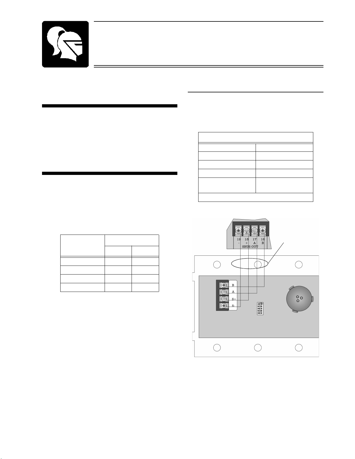
Figure 1: 5865-3 or 5864-4 Connection to the 5820
Table 1: Wire Connections
5865-3 & 5865-4
Terminals
5820 Terminals
Number
Label
Table 2: 5865-3 and 5865-4 Specifications
Specifications
Supervised
Power Limited
guide, refer to the control panel installation
manual IntelliKnight 5820 Analog/Addressable
Fire System P/N 150972 for detail system
information.
Installation and wiring of these devices must be
done in accordance with NFPA 72 and local
ordinances.
Terminate the wiring as shown in Figure 1. See
also Table 1.
B16B
A17A
S+ 18 +
S- 19 -
Table 2 lists the operating specifications for the
5865-3 and 5865-4.
Max. Line Resistance 50
Max. Alarm Current 145 mA
Standby Current 35 mA
Max. Voltage 24 VDC
Operating Temperature 0° to 49° C
Indoor Use Only
Ω
(32° to 120° F)
Page 2
Models 5865-3 and 5865-4 Installation Instructions
P/N 151088
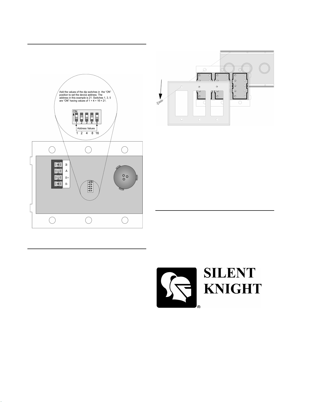
Setting the Device Address
The range of valid addresses is 1 -31 (0 is an
Figure 2: Setting the Device Address
Mounting the 5865-3
Figure 3: 5865-3 Mounting
Mounting the 5865-4
Note:
Cover Plate
5865-3
3-gang
Electrical Box
Cover
Plate
Screw
invalid address). Refer to Figure 2 to set the dip
switches to the desired address.
2. Place the 5865-3 into the 3-gang electrical
box. See Figure 3.
3. Place cover plate over the top of the 5865-3
and align the holes. See Figure 3.
4. Insert the six cover plate screws into six
screw holes on the 3-gang electrical box.
5. Screw the six cover plate screws all the way
in until the cover plate fits firmly against the
5865-3 and the electrical box. Do Not over
tighten.
The 5865-3 mounts into a standard 3-gang
electrical box.
Follow these steps to mount the 5864-3:
1. Make sure that the 5865-3 is properly wired
to the control panel. See Figure 1.
The 5865-4 mounts into a standard 4-gang
electrical box.
Use the same procedure as used for mounting
the 5865-3.
The 5865-4 uses 8 cover plate screws.
7550 Meridian Circle
Maple Grove, MN 55369-4927
612-493-6455
800-328-0103
Fax: 612-493-6475
© 1997 Silent Knight
P/N 151088, Rev A, 11/97
 Loading...