

Page 1
SILENT
KNIGHT
By Honeywell
®
5824 Serial/Parallel Interface
Gateway Module
Installation Instructions
The 5824 Serial/Parallel Interface Gateway
Module (5824) connects a Silent Knight fire
alarm control panel (FACP) directly to a printer
to print event history. You can also print system
event logs in real time and detector status from
SK addressable FACPs.
Note: Installation and wiring of this device must be done
in accordance with NFPA 72 and local ordinances.
Specifications
Operating Voltage: 24VDC
Current (Alarm and Standby): 45 mA
Max Per FACP
Addressable FACPs: 8; 5208 FACP: 1
Ambient Temperature: 32°F to 120°F (0°C to 49°C)
Max Wiring Distance from FACP: 6000 ft. (1829 m)
Mounting: Surface
Dimensions: 6”W x 7-3/4”H x 1-7/16”D
(15.2 cm W x 19.7 cm H x 3.7 cm D)
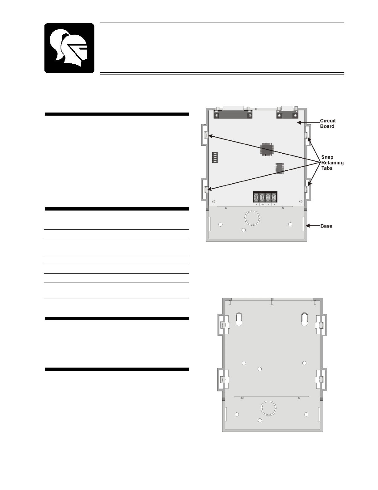
orientated in Figure 1) and lifting the circuit
board out.
Figure 15824 Circuit Board And Enclosure Base
3. Remove knockout if running wires through
the back of the base, and mount the base
using any of the mounting holes provided
(Figure 2). Mounting hardware not included.
Compatibility
The 5824 is compatible with all Silent Knight
addressable FACPs and with the 5208
conventional FACP.
Mounting
The 5824 has a plastic enclosure that is surface
mounted.
To mount the 5824 enclosure:
1. Remove the 5824 cover. Use a small screw
driver if necessary.
2. Remove the 5824 circuit board from the
enclosure base by pushing outward on one of
the snap retaining tabs at the bottom (as
Figure 2: Enclosure Base
P/N 151392
Page 2
5824 Serial/Parallel Interface Gateway Module Installation Instructions
4. Snap the circuit board back in the base so the
snap retaining tabs hold it in place.
Note: It may be necessary to wire to the circuit board
before placing it back in the base. See Wiring to a
FA C P .
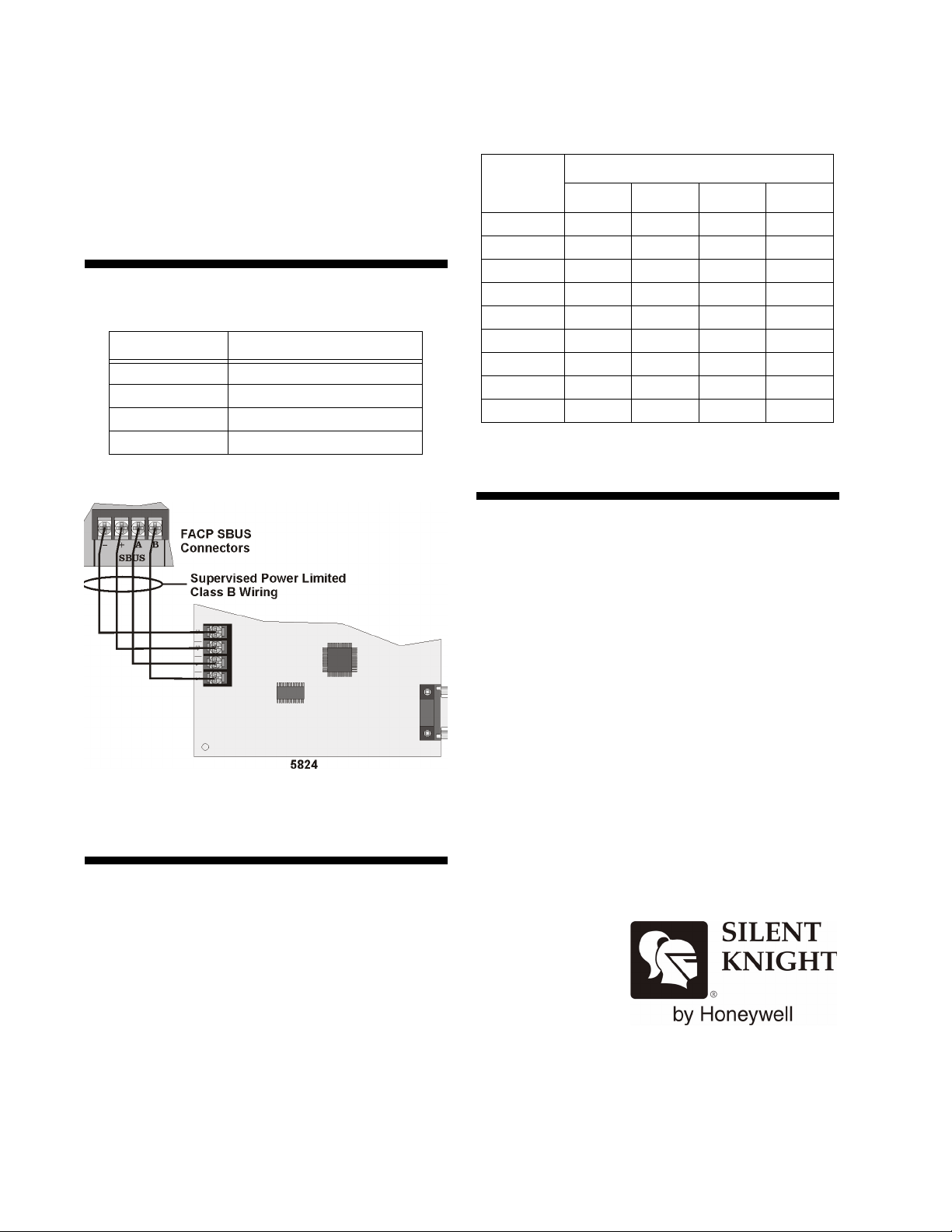
Wiring to a FACP
See Table 1 and Figure 3 to terminate the wiring.
Table 1: 5824 to FACP Connections
5824 Terminals FACP SBUS Terminals
BB
AA
S+ +
S- - (or GND)
ID Number
0 * Down Down Down Down
1 Up Down Down Down
2 Down Up Down Down
3 UpUpDownDown
4 Down Down Up Down
5 UpDownUpDown
6 DownUpUpDown
7 UpUpUpDown
8 Down Down Down Up
* Zero is not used. Up = On Down = Off
Connecting to a Printer
Table 2: ID Dip Switch Settings
Switches
1234
Figure 3: Wiring the 5824 to the FACP
Setting DIP Switches
Each module on a Silent Knight FACP requires
an ID number which is set using the DIP
switches on the 5824 circuit board. Refer to
Table 2 to see how to position the DIP switches
for the desired ID number. See the FACP
installation manual for specific information on
device ID assignments.
Connect the printer cable to the serial or parallel
on the 5824 and then connect it to the printer.
Printer cable not included.
Maple Grove, MN 55369-4927
763-493-6455 or 800-328-0103
© 2005 Silent Knight PN 151392A
7550 Meridian Circle
Fax: 763-493-6475
http://www.silentknight.com
2 P/N 151392
 Loading...