

Page 1

Contents
Section 1
Introduction
1.1 Overview of System Features .....................................................................................1-1
1.1.1 Compatible Modules ........................................................................................1-2
1.1.2 Accessory Enclosure ........................................................................................ 1-5
1.2 How to Use this Manual .............................................................................................. 1-5
1.3 How to Contact Silent Knight ...................................................................................... 1-5
1.4 Agency Requirements .................................................................................................. 1-6
1.4.1 Telephone Requirements ................................................................................. 1-6
1.4.2 FCC Warning ................................................................................................... 1-6
1.4.3 UL Requirements ............................................................................................. 1-7
1.4.3.1 Household Burglary Warning System ................................................... 1-8
1.4.3.2 Grade A Mercantile ...............................................................................1-8
1.4.3.3 Commercial & Residential Fire Di gital Alarm Communicator Transmitter
Hardware: ............................................................................................................ 1-9
Programming: ......................................................................................................1-9
1.4.3.4 Access Control UL-294 .........................................................................1-9
.................................................................................................................1-1
(DACT) UL 864, NFPA 72 (Chapter 4) 1-9
Section 2
Quick Start
2.1 Setting System Time and Date ..................................................................................... 2-2
To set the time: .................................................................................................... 2-2
To set the date: ...................................................................................................2-2
2.2 Sending Data to the Panel ............................................................................................ 2-3
2.3 Identifying Serial Numbers and Revision Levels ........................................................2-4
2.3.1 Operating System Revision Level ................................................................... 2-4
2.3.2 Hardware Revision Levels and Serial Numbers ..............................................2-4
2.4 Installation Records ..................................................................................................... 2-4
2.4.1 Serial Number Quick Reference ......................................................................2-5
2.4.1.1 Zone Record .......................................................................................... 2-6
150961 i
....................................................................................................................2-1
Page 2

Model 4821/4820 Control/Communicator Installation Manual
Section 3
Access Control Installation and Operation
3.1 Model 4421 Installation ............................................................................................... 3-1
3.1.1 Model 4421 Connection to the 4821 ................................................................ 3-3
3.1.2 4205 Touchpad Connection to 4421 ................................................................ 3-4
3.2 Card/Proximity Reader Installation .............................................................................3-5
3.2.1 Card Reader Specifications .............................................................................. 3-5
3.2.2 Mounting ..........................................................................................................3-5
3.2.3 Wiring the 4300 Swipe Card Reader ...............................................................3-7
3.2.4 Wiring the 4330, 4340 and 4350 ProximityReaders ........................................ 3-8
3.3 Wiring the 4860C Touchpad for Door Access ............................................................ 3-9
3.4 Access Control Operation .......................................................................................... 3-10
3.4.1 Access Control Touchpad Menus ..................................................................3-10
3.4.2 End-User Operation .......................................................................................3-11
3.4.3 Manually Changing Door Schedules .............................................................3-12
3.4.4 Viewing Door Status ...................................................................................... 3-12
............................ 3-1
3.4.5 Anti-Passback Feature ................................................................................... 3-13
3.4.6 Anti-Passback Operations .............................................................................. 3-14
3.4.7 Bulk Loading Access Cards ........................................................................... 3-14
3.5 Egress Fail-safe Override Application .......................................................................3-15
Section 4
Control Panel Description and Installation
4.1 Environmental Specifications ......................................................................................4-1
4.2 Electrical Specifications ..............................................................................................4-1
4.3 Board Layout ............................................................................................................... 4-2
4.4 Terminal Strip Description .......................................................................................... 4-3
4.5 Power Limiting Circuits ............................................................................................... 4-4
4.6 Power Switch ...............................................................................................................4-5
4.7 Mounting the Model 4821/4820 Panel ........................................................................ 4-5
4.8 Wire Routing ................................................................................................................4-6
4.9 Current Draw Worksheets ........................................................................................... 4-7
............................ 4-1
4.9.1 Sample Worksheets ........................................................................................ 4-7
ii 150961
Page 3

Contents
4.9.2 Worksheet for Silent Knight Modules ............................................................ 4-9
4.9.3 Worksheet for Auxiliary Devices (not Silent Knight) ...................................4-10
4.9.4 Battery Calculation Worksheet ...................................................................... 4-11
4.9.5 Standby Current For DACT Compliant Installations .................................... 4-11
4.10 AC Power Transformer ..............................................................................................4-12
4.11 Backup Battery Connection .......................................................................................4-13
4.12 4195 Auxiliary Power Supply Installation ................................................................. 4-14
4.13 SBUS .........................................................................................................................4-15
4.13.1 SBUS Modules ..............................................................................................4-15
4.13.2 Distribution of Modules Between SBUS1 and SBUS2 ................................. 4-16
4.13.3 Number of SBUS Devices .............................................................................4-17
4.14 Touchpad Installation ................................................................................................4-18
4.14.1 Touchpad Specifications ................................................................................ 4-18
4.14.2 Mounting Touchpads .....................................................................................4-18
4.14.3 Wiring Touchpads .......................................................................................... 4-19
4.15 Zone Installation ........................................................................................................ 4-20
4.15.1 Zone Hardware Specifications ....................................................................... 4-20
4.15.2 Maximum Number of Zones per System ....................................................... 4-20
4.15.3 Zone Configuration ........................................................................................ 4-21
4.15.4 Zone Configuration Examples .......................................................................4-22
4.15.5 Wiring a 4860C as an Input Zone .................................................................. 4-24
4.15.6 Zone Response (Debounce) Speed ................................................................ 4-25
4.16 Smoke Detector Wiring and Operation ..................................................................... 4-26
4.16.1 Smoke Detector Compatibility ...................................................................... 4-26
4.16.1.1Smoke Reset Cycle .............................................................................. 4-26
4.16.1.2Smoke Verification Cycle ................................................................... 4-26
4.16.2 Four-Wire Smoke Detector Wiring ...............................................................4-27
4.17 Speaker Wiring .......................................................................................................... 4-28
4.17.1 Internal Speaker Wiring ................................................................................. 4-28
4.17.2 External Speaker Wiring ................................................................................4-28
4.18 Bell Wiring ................................................................................................................4-29
4.18.1 Residential Type Bell Wiring ........................................................................ 4-29
4.18.2 Commercial Bell Wiring ................................................................................ 4-30
4.19 4884 Bell Module wiring ........................................................................................... 4-31
150961 iii
Page 4

Model 4821/4820 Control/Communicator Installation Manual
4.20 Telephone Line Connection ....................................................................................... 4-32
4.20.1 Second Phone Line Monitor Connection (Model 4875) ................................ 4-33
4.20.2 Ground Start Relay Connection (Model 5211) .............................................. 4-34
4.21 Built-in Relay .............................................................................................................4-34
4.22 DACT Compliant Wiring .......................................................................................... 4-35
4.22.1 Trouble Output Relay .................................................................................... 4-35
4.22.2 Monitoring an Existing Fire Alarm Control ..................................................4-36
4.22.3 Monitoring A Sprinkler System ..................................................................... 4-37
Section 5
System Operation
5.1 Partitions and Areas .....................................................................................................5-1
5.2 Touchpad Models ........................................................................................................5-4
5.3 Display Messages ........................................................................................................ 5-5
5.3.1 Power Up Messages ......................................................................................... 5-5
5.3.2 Normal Display Messages ............................................................................... 5-6
5.3.3 System Status Messages .................................................................................. 5-6
5.4 Touchpad Buttons ........................................................................................................ 5-7
5.5 Toggle and Interactive Menu Operations .................................................................... 5-8
5.6 Interactive Menu Overview ......................................................................................... 5-9
5.7 System Operation Summary ......................................................................................5-10
5.8 System Maintenance Operations Summary ............................................................... 5-14
5.9 System Test Descriptions ........................................................................................... 5-16
5.9.1 Walk Test ....................................................................................................... 5-16
5.9.2 Dialer Test ...................................................................................................... 5-16
................................................................................................5-1
5.9.3 Dialer Reset .................................................................................................... 5-16
5.10 Communicating with the Computer ........................................................................... 5-17
5.10.1 Sending Data To and From the Panel ............................................................5-18
5.11 Audible Signals Description and How to Reset ......................................................... 5-19
iv 150961
Page 5

Section 6
Contents
Programming
6.1 Downloading ................................................................................................................6-1
6.2 Touchpad Programming ..............................................................................................6-1
6.2.1 General Operation ............................................................................................ 6-1
6.2.2 The Main Menu ............................................................................................... 6-2
6.2.2.1 1-Install Device ..................................................................................... 6-3
6.2.2.2 2-Edit System Options ........................................................................... 6-3
6.2.2.3 3-Edit Partition ......................................................................................6-4
6.2.2.4 4-Edit Ph. Lines ..................................................................................... 6-4
6.2.2.5 5-Reprt Accounts ................................................................................... 6-5
6.2.2.6 6-Print Accounts ....................................................................................6-5
6.2.2.7 7-Edit Profiles ........................................................................................ 6-6
6.2.2.8 Selecting Characters for Profile Names ................................................ 6-7
Using the LCD Prompts ...................................................................................... 6-7
Using the Chart (Table 6-3) ................................................................................ 6-8
6.2.2.9 8-Edit Schedules ....................................................................................6-9
.............................................................................................................6-1
6.2.2.109-Delete Options .................................................................................. 6-10
Activating Safe Mode ....................................................................................... 6-10
Quitting Safe Mode ........................................................................................... 6-10
6.3 Programmable Options .............................................................................................. 6-11
6.3.1 System Devices List ....................................................................................... 6-11
6.3.1.1 General System Options Screen .......................................................... 6-11
6.3.1.2 Dialer Screen .......................................................................................6-14
6.3.1.3 Devices Screen .................................................................................... 6-15
6.3.2 Partition List and Menus ................................................................................6-16
6.3.2.1 Partition Options Screen ...................................................................... 6-16
6.3.2.2 Touchpads / Card Readers Screen ....................................................... 6-20
6.3.2.3 Zones Screen ....................................................................................... 6-23
6.3.2.4 Reporting Accounts Screen .................................................................6-27
6.3.2.5 Areas Screen ........................................................................................ 6-30
6.3.3 Time Schedules Screen .................................................................................. 6-31
Time Ranges .....................................................................................................6-31
6.3.4 Universal Schedules ....................................................................................... 6-32
6.3.5 User Profiles Screen .......................................................................................6-33
6.3.6 Users Screen .................................................................................................. 6-34
150961 v
Page 6

Model 4821/4820 Control/Communicator Installation Manual
Section 7
Reporting
7.1 Compatible UL Listed Receivers ................................................................................. 7-1
7.2 SIA Event Codes .......................................................................................................... 7-2
7.3 Ademco Contact ID Event Codes ................................................................................ 7-6
7.4 ASCII Event Descriptions .........................................................................................7-10
.......................................................................................................................7-1
Section 8
Troubleshooting
8.1 Error Messages ............................................................................................................ 8-1
8.2 Before You Call Technical Support ............................................................................. 8-2
....................................................................................................8-1
vi 150961
Page 7

Section 1
Introduction
The Model 4821/4820 is a control/communicator for use in residential and commercial
security applications, commercial and residential fire applications. The Model 4821 includes a
sophisticated access control system, through which you can monitor and control user access to
specific areas of a building (see Section 3 for detailed information on access control).
1.1 Overview of System Features
4820 4821 System Feature
3
3
3
3
3
3
3
3
3
3
3
3 Can use the Model 4421 Door Access Module as an expansion device.
3 8 partitions, 8 areas within each partition
3 32 reporting accounts
3 24 touchpads / card readers
3
3 100 User Profiles
3 1800 User Codes
3 50 Time Schedules (with 20 time ranges each)
3 8 Universal Schedules (with 20 time ranges each)
3
400 zones, 16 on 4821/4820 board, additional available with expansion devices
(Model 4815 zone expander, Model 4825 zone expander, Model 4860C touchpad)
8 reporting accounts
One monitored phone line on 4821/4820 board, expandable to two lines with Model
4875 Second Phone Line Expander
20 User Profiles
500 Users Codes
25 Time Schedules (with 20 time ranges each)
2.5 amps power available, expandable to 5.0 amps with 4195 Auxiliary Power
Module
The 4821 and 4820 are shipped with a Model 9227 transformer and 16 Model 7628EOL
resistors (each 4.7 k ohm).
150961 1-1
Page 8

Model 4821/4820 Control/Communicator Installation Manual
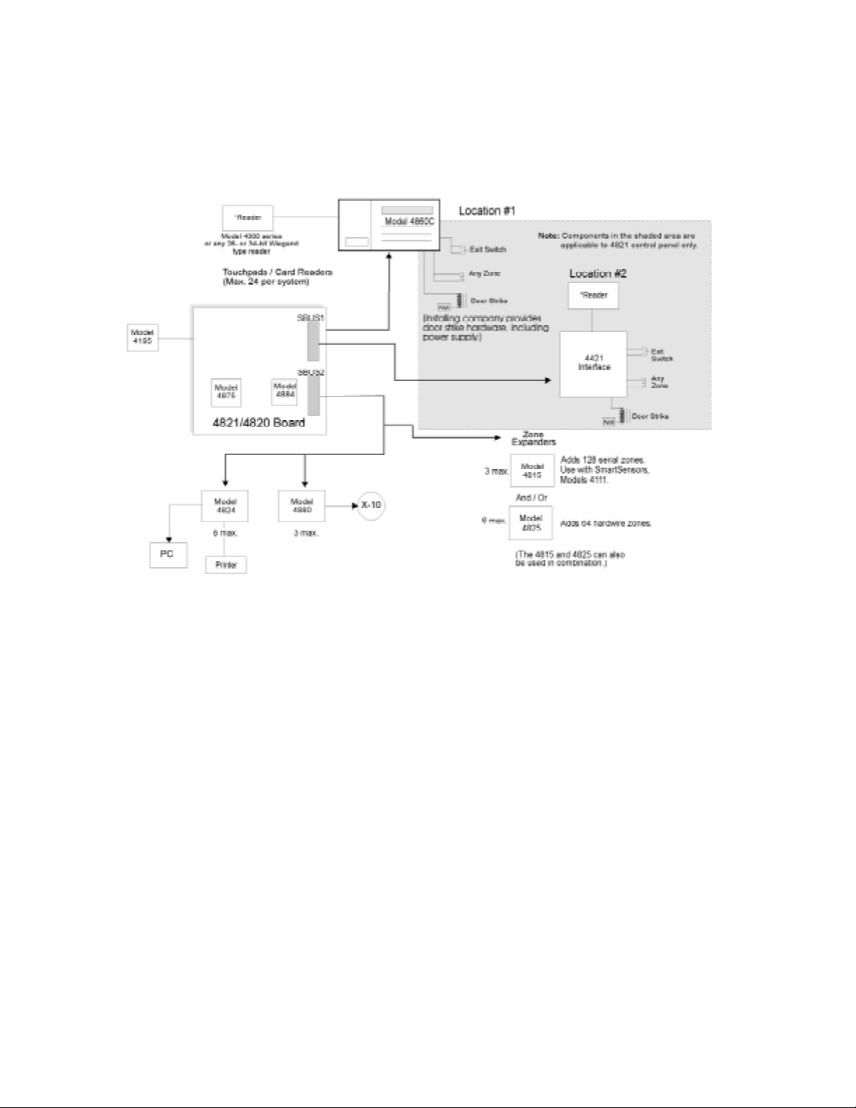
1.1.1 Compatible Modules
Table 1-1 shows the modules available for use with the 4821/4820. The third column of the
chart shows where to find installation instructions for the module. (See Figure 1-1 for a block
diagram or compatible units.)
Table 1-1: Modules Compatible with the Model 4821/4820
Model Description
4195 Auxiliary Power Supply Provides an additional 2.5 amps of power and allows
for a second 12-volt, 7.0 AH battery to be added to the
system.
4815 Serial Zone Expander 128-Zone Serial Expander. Used with SmartSensors.
4111 SmartSensors Serial sensors for use with the 4815.
4114 End-of-Line Resistor 1.43K ohm EOL resistor for use with Model 4111
SmartSensor. The 4114 is required for UL installations.
4181X10 Powerline Interface For connecting X10 modules to the 4880.
(Note: X10 modules are not UL listed for fire and
burglary applications.)
1 2
4205 Slimline Touchpad
For access control installations. Requires the 4421 Door
Access Module (see note 1 below). Cannot be us ed with
the 4820 control panel.
1
4300 Classic Wiegand Swipe
Card Reader
26-bit Wiegand type swipe card reader for indoor or
outdoor use. Has fully encapsulated head to withstand
tampering and environmental damage. Compatible with
4301 swipe cards.
1 3
4301 Wiegand Acces Card
1
4305 Proxima Clip-on Badge
1
Proximity Card,
4306 Proxima
For use with Model 4300 Card Swipe Reader.
For use with Model 4330/4340/4350 readers.
Laminated Vinyl Proximity
1
4308 Proxima Proximity
Card,
Key tag
1
4330 Proxima Mullion Mount
Mullion mount type reader, 26- or 34-bit selectable. Section 3.2.4 of this manual
Proximity Card Reader
1
4340 Proxima Standard Range
Standard range reader, 26- or 34-bit selectable. Section 3.2.4 of this manual
Proximity Card Reader
1
4350 Proxima Medium Range
Medium range reader, 26- or 34-bit selectable. Section 3.2.4 of this manual
Proximity Card Reader
1 3
4421 Door Access Module
Hardware interface for 26-bit or 34-bit Wiegand type
card readers and for the 4205 Slimline Touchpad.
See Section (for more
information)
Section 4.12 of this manual.
4815 Installation
section of
this binder (P/N 150909 ).
4815 Installation
section of
this binder (P/N 150909 ).
4815 Installation
section of
this binder (P/N 150909 ).
4880 Installation
section of
this binder (P/N 150912 ).
Section 3.1 of this manu al
Section 3.2.3 of this manual
Section 3.1 of this manu al
1-2 150961
Page 9

Table 1-1: Modules Compatible with the Model 4821/4820
Introduction
Model Description
4824 Serial/Printer Interface Provides one RS-232 serial por t and one par allel prin ter
port, which can be programmed to output events in
See Section (for more
information)
4824 Installation section of
this binder (P/N 150911).
English text or in either of the reporti ng formats (SIA or
Ademco Contact ID).
Can be used to send data to the panel for on-site
programming or for connection to a PC running
4850ACAS software.
4825 Hardwire Zone Expander 64-Zone Hardwire Expander. 4825 Installation section of
this binder (P/N 150910 ).
4880 Status Output Module Provides 16 outputs and 4 relays that are fully
programmable. Also provides an X10 interface.
4880 Installation section of
this binder (P/N 150912 ).
(Note: X10 modules are not UL listed for fire and
burglary applications.)
4860C Touchpad Fully featured commercial touchpad using an LCD to
annunciate alarms, troubles and other system messages.
Has 2 zone inputs that can be used for hardwiring any
type of zone input, or for door access. Has a built-in
card reader interface.
In this manual, refer to Section
4.14 for installation as a
system touchpad.
Section 3 and 5 for operation
of system touchpad.
Section 4.15.5 for installation
as a system zone.
4860R (gray) and 4860Rx
(bright white) Touchpad
Fully featured residential touchpad using an LCD to
annunciate alarms, troubles and other system messages.
Section 4.14 of this manual for
installat i on instructio ns .
4875 Second Ph one Line
Monitor
Only difference between these two models is color of
plastic. 4860R is gray; 4860Rx is bright white.
Provides termination for second phone line. Required if
two phone lines are used.
Section 4 of this manual for
operation instructions.
Section 4.20.1 of this manual.
4884 Bell Module Provides termination for a supervised bell Section 4.19 of this manual.
4890 Accessory Enclosure Secured cabinet to mount additional modules such as
Section 1.1.2 of this manual.
4815, 4421, 4880 etc. (Required for UL installations.)
5211 Ground Start Relay Required for applications usi ng a ground start telepho ne
Section 4.20.2 of this manual.
network. (Not UL listed.)
6712 Battery 12 VDC 7 amp hour Gell Cell battery for use with the
Section 4.11 of this manual.
4821/4820.
7628 End-of-Line Resistor 4.7 k ohms EOL resistor used for all input zones
Section 4.15 of this manual.
(except 4815 SmartSensor zones).
16 EOLs are shipped with the 4821/4820.
7860 Telephone Cord RJ31X cord for connecting phone line to the 4821/
Section 4.20 of this manual.
4820.
9000 Receiver For use with the SIA-20 format. Section 7 of this manual.
(Section 7 also lists other
receivers compatible with the
4821/4820.)
150961 1-3
Page 10
Model 4821/4820 Control/Communicator Installation Manual
1. Not UL listed with 4820 control panel.
2. Not UL listed for access control.
3. Can not be used with the 4820 control panel.
Figure 1-1 Model 4821/4820 and Compatible Modules
1-4 150961
Page 11
Introduction
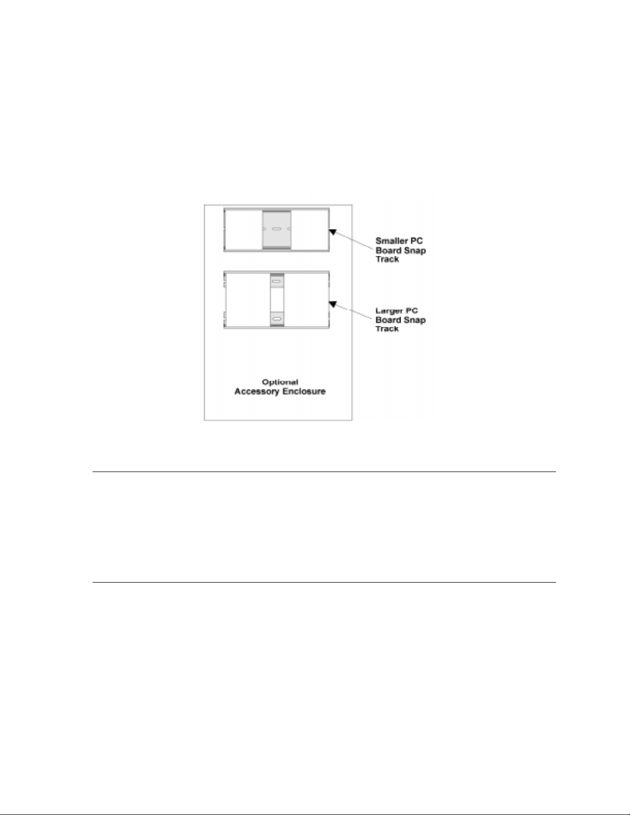
1.1.2 Accessory Enclosure
In applications where more than two additional 4815 modules are to be used in the control
panel “snap tracks”, a model 4890 alarm accessory enclosure is required. (See Section 1.4.3
for UL requirements.) The Model 4890 has the same dimensions as the 4821/4820 control
panel enclosure and contains two additional snap tracks. One snap track is designed for
smaller width boards such as the 4815 control module. The other snap track is sized to
accommodate the larger PC boards such as the 4824, 4880, and 4421 modules.
Figure 1-1 4890 Accessory Enclosure
1.2 How to Use this Manual
The manual uses the following conventions:
• A clear rectangle represents a touchpad button.
• Pages of the manual are numbered by section. For example, a page numbered as “5-1” is
Page 1 of Section 5.
1.3 How to Contact Silent Knight
If you have a question or encounter a problem not covered in this manual, contact: Silent
Knight Technical Support at 800-328-0103 (or 612-493-6455). To order parts, contact Silent
Knight Sales at 800-446-6444 (or 612-493-6435).
150961 1-5
Page 12

Model 4821/4820 Control/Communicator Installation Manual
1.4 Agency Requirements
1.4.1 Telephone Requirements
If requested by the telephone company, the following information must be provided before
connecting this device to the phone lines:
A. Manufacturer: Silent Knight Security Systems
B. Model Number: 4821/4820
C. FCC Registration Num be r: AC6USA-2275 5-AL-E
D. Type of jack (to be installed by the
telephone company):
Ringer equivalence: 0.9B
RJ31X
This device may not be connected directly to coin telephones or party line services.
This device cannot be adjusted or repaired in the field. In case of trouble with the device,
notify the installing company or return the device to the manufacturer:
Silent Knight Security Systems
7550 Meridian Circle
Maple Grove, MN 55369-4927
800-328-0103 or 612-493-6455
The telephone company may make changes in its facilities, equipment, or procedures that
could affect the operation of the equipment. If this happens, the telephone company will
provide advance notice to allow you to make the necessary modifications to maintain
uninterrupted service.
1.4.2 FCC Warning
This device has been verified to comply with FCC Rules Part 15. Operation is subject to the
two following conditions: (1) This device may not cause radio interference, and (2) This
device must accept any interference received including interference that may cause undesired
operation.
1-6 150961
Page 13

Introduction
1.4.3 UL Requirements
If installed in accordance with these requirements, the Model 4821/4820 is UL listed for
Grade A Mercantile, Local Police Station Connect with Basic Line Security, and Grade B and
C Central Station Service.
Follow the requirements below if you are installing a UL listed application. See Section
1.4.3.1 for Household Fire and Burglary Warning System installation requirements. See
Section 1.4.3.2 for Grade A Mercantile installation requirements.
1. The Model 4860C (commercial) or 4860R (residential) touchpad must be used. Each
SBUS must have at least one touchpad connected (minimum of two touchpads per installation).
2. Entry delays must not be longer than 45 seconds. An exit delay must not be longer than 60
seconds.
3. All panic zones (including touchpad panic zones) must be programmed as silent and invisible.
Note: Silent and invisible reports can be seen by pressing status or reviewing the event history.
4. The Audible Trouble Alert When Armed option (programmed in Area Menu) must be
selected.
5. Do NOT select the following optional features:
Automatic closing or opening (programmed in the Area Menu)
Swinger Bypass Timeout (programmed in Area Menu)
6. Partitions are allowed in UL burglary installations only if the protected premises falls
under one ownership and the operation of a single authority. An example of an acceptable
installation is a common building operated by one company which may need to subdivide
the system to allow independent entry and exit. A strip mall is an example of an application that would
zones. (See Item 9. below for additional information about partitioning.)
7. If the cross-alarm feature is used, it must be used only by detectors that share a common
field of view.
8. A complete functional checkout of the system must be performed any time the system is
programmed or reprogrammed. (Zone bypassing or other temporary changes necessary for
troubleshooting are an exception to this requirement.)
9. Bells must be the primary source of alarm annunciation. Speakers can be used as an additional source. Grade C Central Station installations are an exception; bells are not required
in these installations. In a multi-partition system, bells must be protected by a
24-hour circuit.
not
be allowed in a UL installation. Partitioning cannot be used for fire
10. Opening and closing signals must be enabled in a Central Station installation.
150961 1-7
Page 14

Model 4821/4820 Control/Communicator Installation Manual
11. In applications requiring more than two modules 4815 to be located in the control panel
snap track, a model 4890 alarm accessory enclosure is required. (See Section 1.1.2.)
12. Do not eliminate the default I/O programming script. Doing so could cause the bell sounds
to be deleted from the system.
Note: The script can be modified to include add itional functions, but the default statements must remain intact.
1.4.3.1 Household Burglary Warning System
If you are installing the 4821/4820 in a UL listed residential installation, follow the
requirement below in addition to those listed in Section 1.4.3.
The Audio Shutdown Delay option must be programmed as 4 minutes.
1.4.3.2 Grade A Mercantile
For a Grade A Mercantile listing, follow the requirements below in addition to those listed in
Section 1.4.3.
1. You must program a time schedule for auto testing to occur (programmed in Time
Schedules Menu).
2. The Audio Shutdown Delay option must be programmed to 15 minutes.
3. A listed tamper switch must protect the inside front door of the enclosure. This switch
must be connected to an intrusion input zone of the control unit which is programmed as a
perimeter zone.
4. All unused knockout holes on the cabinet must be plugged using bolts and washers.
(Model 7600 is a kit available from Silent Knight for this purpose.) See Section 4.7 for
installation instructions.
5. Four pan head screws #8x3”, type AB (thread forming tapping screws) must be placed in
the 4821/4820 cabinet cover to increase the panel’s attack resistance.
6. A separately listed Ademco AB-12 Bell in Box must be used with the control unit.
7. The tamper switches of the alarm bell must be connected to a 24-hour zone. No other initiating devices may be connected to this loop. The outer housing of the bell box must be
grounded. The bell circuit should be installed in accordance with UL requirements.
8. All bell wiring must be run in its own conduit and must be connected to the control unit
using its own knockout hole.
1-8 150961
Page 15

Introduction
1.4.3.3 Commercial & Residential Fi re Digital Alarm Communicator
Transmitter (DACT) UL 864, NFPA 72 (Chapter 4)
The DACT listing allows the 4821/4820 to be used to monitor an existing local fire alarm
control and/or a sprinkler system. For the 4821/4820 to be used as a DACT, the following
requirements must be complied with:
Hardware:
• A minimum of one 4860C Commercial Touchpad.
• Two 4165 Transformer Covers.
• A 4195 Auxiliary Power Supply.
• A 4875 Dual Phone Line Module.
• A 4884 Bell Module.
• Two 6712 12 VDC 7AH Standby Battery or Equivalent.
• Power switch bypass jumpers must not be cut.
Programming:
The following options must be selected when programming the control panel. (See Section 6
Programming for programming information.):
1. In the Low AC Report Time (Section 6.3.1.1) must be set between 6 and 12 hours.
2. In the Phone Line Enabled (Section 6.3.1.2) 2 Phone Lines option must be must be
selected.
3. In the Ground Start Telephone Network Used option (Section 6.3.1.2) must remain disabled.
4. In the Phone Line Monitor Enabled option (Section 6.3.1.2) the Line Monitor option must
be selected.
1.4.3.4 Access Control UL-294
All 4860C touchpads must be located within the protected premises. The 4820 is not li sted for
access control.(See Section 3 for access control installation information.)
150961 1-9
Page 16

Model 4821/4820 Control/Communicator Installation Manual
1-10 150961
Page 17

Section 2
Quick Start
This section is intended to help you determine if any problems exist with the system you are
about to install. Perform the steps below in the order shown here.
1. Wire a touchpad to one of the four-wire serial buses (SBUS). See Section 4.14 for more
information. (See Note below.)
2. Plug in the transformer and apply AC.
3. Hook up the battery.
4. The touchpad will initialize. Several messages, including the touchpad seria l number, will
display for approximately one second. When the message “482x Engaged” (x indicates
that the display would read 1 for a 4821, or 0 for a 4820) is displayed, it means the system
has booted up successfully. The default date and time is displayed.
5. Set system date and time. You may use the default code to test the system. See the instructions on the next page for more information.
If you are able to set the date and time successfully , it means the sy stem is up and running.
6. From here you can send your programmable options to the panel, if you have programmed
them through the Model 5580 Upload-Download Software. (See Section 2.2.)
Note: To at tach a t emporar y touchp ad to th e system, you do not need to kn ow its se rial n umber. To per manentl y
attach any SBUS device, including a touchpad, you must enter its serial number into the system.
150962 2-1
Page 18

Model 4821/4820 Control/Communicator Installation Manual
2.1 Setting System Time and Date
To set the time:
1. Press
2. At the menu prompt, enter to select “Time”.
3. Enter digit(s) for hour in 24-hour military format, then press .
4. Enter digit(s) for minute, then .
1 ENTER
[Code]. (Installer Code is factory-programmed as 1234.)
1
ENTER
ENTER
Note that if the “Auto DST Adjustment” feature has been enabled, a message will display
when you set the time.
Example:
To change the system time to 3:45 p.m., the keystrokes are:
1 ENTER 1
1 5 ENTER
4 5 ENTER
[Code]
To set the date:
1 ENTER
1. [Code]
2. At the menu prompt, enter to select “Date”.
3. Enter digit(s) for month, then press .
4. Enter digit(s) for date, then press .
5. Enter four digits for year, then press .
2
ENTER
ENTER
ENTER
Example:
To change the system date to July 15, 1996, the keystrokes are:
1 ENTER 2
[Code]
7 ENTER
1 5 ENTER
1 9 9 6 ENTER
2-2 150962
Page 19

2.2 Sending Data to the Panel
See Section 5.10 of this manual for complete information about communication.
Quick Start
1. Press
4 ENTER
[Installer or Maintenance Code]
2. At the menu, select:
1
for Internal Phone. This option is for downloading via the phone lines.
2
for 4824 Modem. With this type of communication, a Hayes compatible modem is con-
nected to both the 4824 and the PC, allowing for faster data transmission.
3
for 4824 Direct. This option is for directly connecting the 4824 to the computer using a
null modem cable (both the computer and the 4821/4820 are on-site).
3. If you select either 4824 option (2 or 3), you will be prompted to select the 4824 from the
list of 4824s installed in the system.
4. If the phone number that displays is not correct, enter the correct digits and press . (If
the phone number is correct, press to bypass this step.) If you have selected the 4824
ENTER
ENTER
Direct option, this step will not appear.
5. If the Account number that displays is not correct, enter the correct digits and press .
(If the account number is correct, press to bypass this step.)
ENTER
ENTER
6. The system will attempt to communicate. If the communication attempt was successful,
the panel will re-initialize. Do not power the system down during the re-initialization
period.
Note: If the 5580 has no task in its queue, the panel will always send an upload. The 5580 must have a download
in its queue for this account in order for the download to occur.
150962 2-3
Page 20
Model 4821/4820 Control/Communicator Installation Manual
S/N000006034821H.
1
2.3 Identifying Serial Numbers and R evis io n Leve ls
This section describes how to determine the levels of hardware and 4821/4820 software that
are used with your panel.
2.3.1 Operating System Revision Level
Press to see a display of the revision date.
4 STAT
16:51:03
Oct 19 1995
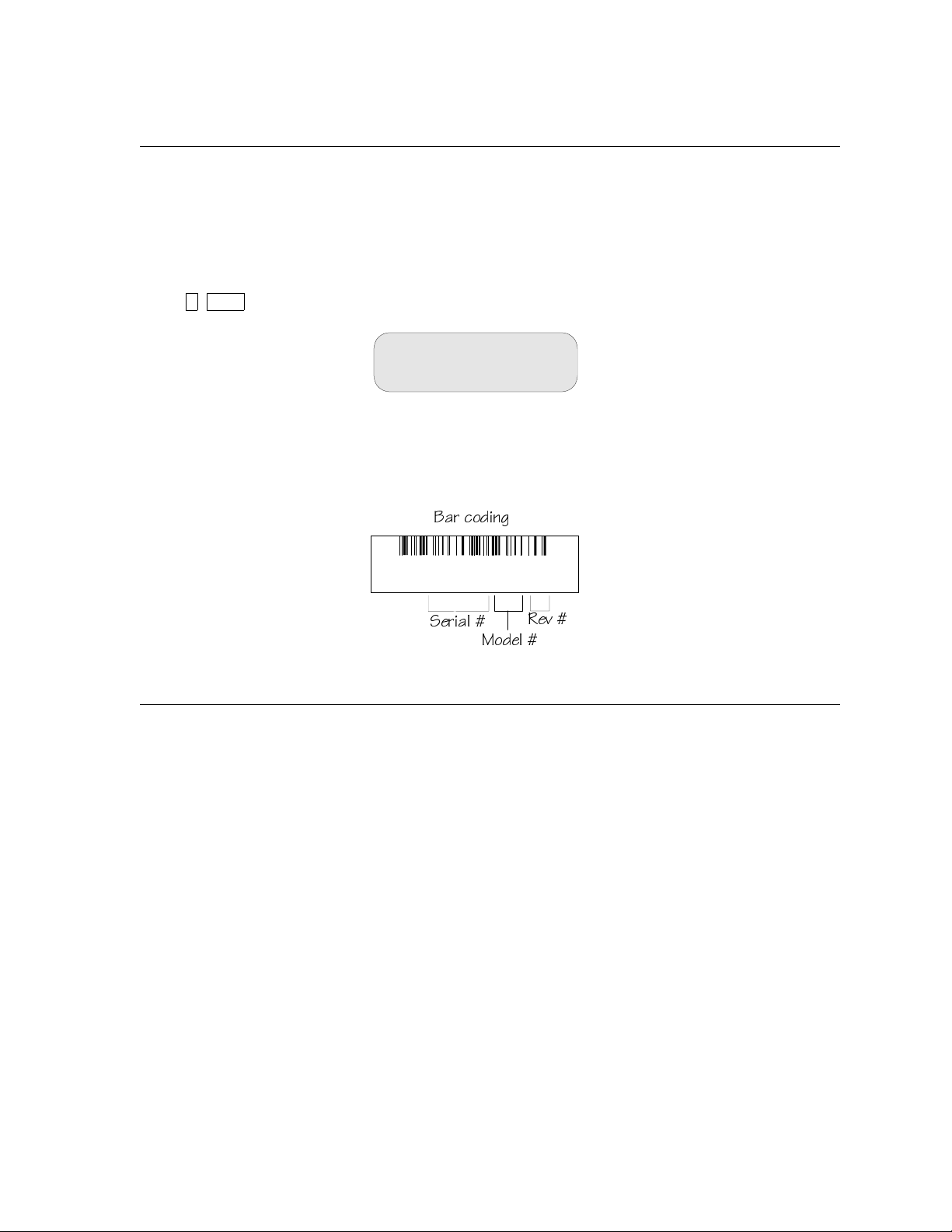
2.3.2 Hardware Revision Levels and Serial Numbers
Hardware revision levels and serial numbers are printed on labels on the circuit board. Look
for “S/N” followed by an 8-digit number.
2Qb S_TY^W
CUbYQ\
=_TU\
BUf
2.4 Installation Records
You can use the following pages to keep a record of options programmed for an installation.
You may want to use the charts for up-front planning of your installations. Copy the pages as
needed for all installations.
2-4 150962
Page 21
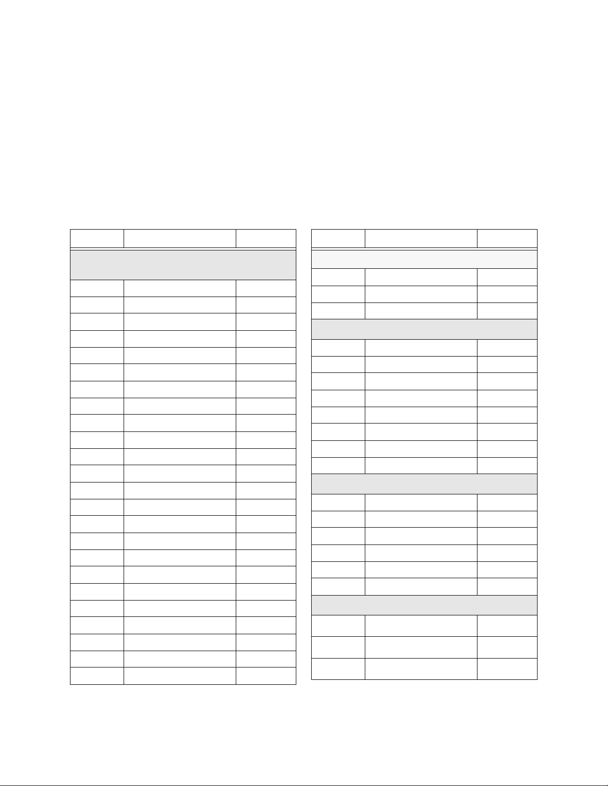
2.4.1 Serial Number Quick Reference
Use the chart below to keep track of hardware device serial numbers.
Customer Name __________________________________
Location ________________________________________
Account Number _________________________________
Installation Code _________________________________
Quick Start
Device # Description Serial #
4421 Door Access Module /
4860 Touchpads
1
2
3
4
5
6
7
8
9
10
11
12
13
14
15
16
17
18
19
20
21
22
23
24
Device # Description Serial #
4880 Status Output Module
1
2
3
4824 Serial/Parallel Module
1
2
3
4
5
6
7
8
4825Hardwire Zone Expander
1
2
3
4
5
6
4815Serial Zone Expander
1
2
3
150962 2-5
Page 22

Model 4821/4820 Control/Communicator Installation Manual
2.4.1.1 Zone Record
Use the charts in this section to record zone identification information.
Table 2-1: Internal Zones
Zone #
Hardware
Point
1 1 2 3 4 5 6 7 8
2 1 2 3 4 5 6 7 8
3 1 2 3 4 5 6 7 8
4 1 2 3 4 5 6 7 8
5 1 2 3 4 5 6 7 8
6 1 2 3 4 5 6 7 8
7 1 2 3 4 5 6 7 8
8 1 2 3 4 5 6 7 8
9 1 2 3 4 5 6 7 8
10 1 2 3 4 5 6 7 8
11 1 2 3 4 5 6 7 8
12 1 2 3 4 5 6 7 8
13 1 2 3 4 5 6 7 8
14 1 2 3 4 5 6 7 8
15 1 2 3 4 5 6 7 8
16 1 2 3 4 5 6 7 8
Location Partition # Areas
2-6 150962
Page 23

4825 Hardwire Zone Expander______Serial Number____________Device Number_____
Zone H/W Pt Location Partition Areas Zone H/W Pt Location Partition Areas
1 1 2 3 4 5 6 7 8 33 1 2 3 4 5 6 7 8
2 1 2 3 4 5 6 7 8 34 1 2 3 4 5 6 7 8
3 1 2 3 4 5 6 7 8 35 1 2 3 4 5 6 7 8
4 1 2 3 4 5 6 7 8 36 1 2 3 4 5 6 7 8
5 1 2 3 4 5 6 7 8 37 1 2 3 4 5 6 7 8
6 1 2 3 4 5 6 7 8 38 1 2 3 4 5 6 7 8
7 1 2 3 4 5 6 7 8 39 1 2 3 4 5 6 7 8
8 1 2 3 4 5 6 7 8 40 1 2 3 4 5 6 7 8
9 1 2 3 4 5 6 7 8 41 1 2 3 4 5 6 7 8
10 1 2 3 4 5 6 7 8 42 1 2 3 4 5 6 7 8
11 1 2 3 4 5 6 7 8 43 1 2 3 4 5 6 7 8
12 1 2 3 4 5 6 7 8 44 1 2 3 4 5 6 7 8
13 1 2 3 4 5 6 7 8 45 1 2 3 4 5 6 7 8
14 1 2 3 4 5 6 7 8 46 1 2 3 4 5 6 7 8
15 1 2 3 4 5 6 7 8 47 1 2 3 4 5 6 7 8
16 1 2 3 4 5 6 7 8 48 1 2 3 4 5 6 7 8
17 1 2 3 4 5 6 7 8 49 1 2 3 4 5 6 7 8
18 1 2 3 4 5 6 7 8 50 1 2 3 4 5 6 7 8
19 1 2 3 4 5 6 7 8 51 1 2 3 4 5 6 7 8
20 1 2 3 4 5 6 7 8 52 1 2 3 4 5 6 7 8
21 1 2 3 4 5 6 7 8 53 1 2 3 4 5 6 7 8
22 1 2 3 4 5 6 7 8 54 1 2 3 4 5 6 7 8
23 1 2 3 4 5 6 7 8 55 1 2 3 4 5 6 7 8
24 1 2 3 4 5 6 7 8 56 1 2 3 4 5 6 7 8
25 1 2 3 4 5 6 7 8 57 1 2 3 4 5 6 7 8
26 1 2 3 4 5 6 7 8 58 1 2 3 4 5 6 7 8
27 1 2 3 4 5 6 7 8 59 1 2 3 4 5 6 7 8
28 1 2 3 4 5 6 7 8 60 1 2 3 4 5 6 7 8
29 1 2 3 4 5 6 7 8 61 1 2 3 4 5 6 7 8
30 1 2 3 4 5 6 7 8 62 1 2 3 4 5 6 7 8
31 1 2 3 4 5 6 7 8 63 1 2 3 4 5 6 7 8
32 1 2 3 4 5 6 7 8 64 1 2 3 4 5 6 7 8
Page 24

4815 Expander Loop1 Addresses Serial Number ________Device Number____
Zone H/W Pt Location Partition Areas Zone H/W Pt Location Partition Areas
Loop1, Addr 1 1 2 3 4 5 6 7 8 Loop1, Addr 33 1 2 3 4 5 6 7 8
Loop1, Addr 2 1 2 3 4 5 6 7 8 Loop1, Addr 34 1 2 3 4 5 6 7 8
Loop1, Addr 3 1 2 3 4 5 6 7 8 Loop1, Addr 35 1 2 3 4 5 6 7 8
Loop1, Addr 4 1 2 3 4 5 6 7 8 Loop1, Addr 36 1 2 3 4 5 6 7 8
Loop1, Addr 5 1 2 3 4 5 6 7 8 Loop1, Addr 37 1 2 3 4 5 6 7 8
Loop1, Addr 6 1 2 3 4 5 6 7 8 Loop1, Addr 38 1 2 3 4 5 6 7 8
Loop1, Addr 7 1 2 3 4 5 6 7 8 Loop1, Addr 39 1 2 3 4 5 6 7 8
Loop1, Addr 8 1 2 3 4 5 6 7 8 Loop1, Addr 40 1 2 3 4 5 6 7 8
Loop1, Addr 9 1 2 3 4 5 6 7 8 Loop1, Addr 41 1 2 3 4 5 6 7 8
Loop1, Addr 10 1 2 3 4 5 6 7 8 Loop1, Addr 42 1 2 3 4 5 6 7 8
Loop1, Addr 11 1 2 3 4 5 6 7 8 Loop1, Addr 43 1 2 3 4 5 6 7 8
Loop1, Addr 12 1 2 3 4 5 6 7 8 Loop1, Addr 44 1 2 3 4 5 6 7 8
Loop1, Addr 13 1 2 3 4 5 6 7 8 Loop1, Addr 45 1 2 3 4 5 6 7 8
Loop1, Addr 14 1 2 3 4 5 6 7 8 Loop1, Addr 46 1 2 3 4 5 6 7 8
Loop1, Addr 15 1 2 3 4 5 6 7 8 Loop1, Addr 47 1 2 3 4 5 6 7 8
Loop1, Addr 16 1 2 3 4 5 6 7 8 Loop1, Addr 48 1 2 3 4 5 6 7 8
Loop1, Addr 17 1 2 3 4 5 6 7 8 Loop1, Addr 49 1 2 3 4 5 6 7 8
Loop1, Addr 18 1 2 3 4 5 6 7 8 Loop1, Addr 50 1 2 3 4 5 6 7 8
Loop1, Addr 19 1 2 3 4 5 6 7 8 Loop1, Addr 51 1 2 3 4 5 6 7 8
Loop1, Addr 20 1 2 3 4 5 6 7 8 Loop1, Addr 52 1 2 3 4 5 6 7 8
Loop1, Addr 21 1 2 3 4 5 6 7 8 Loop1, Addr 53 1 2 3 4 5 6 7 8
Loop1, Addr 22 1 2 3 4 5 6 7 8 Loop1, Addr 54 1 2 3 4 5 6 7 8
Loop1, Addr 23 1 2 3 4 5 6 7 8 Loop1, Addr 55 1 2 3 4 5 6 7 8
Loop1, Addr 24 1 2 3 4 5 6 7 8 Loop1, Addr 56 1 2 3 4 5 6 7 8
Loop1, Addr 25 1 2 3 4 5 6 7 8 Loop1, Addr 57 1 2 3 4 5 6 7 8
Loop1, Addr 26 1 2 3 4 5 6 7 8 Loop1, Addr 58 1 2 3 4 5 6 7 8
Loop1, Addr 27 1 2 3 4 5 6 7 8 Loop1, Addr 59 1 2 3 4 5 6 7 8
Loop1, Addr 28 1 2 3 4 5 6 7 8 Loop1, Addr 60 1 2 3 4 5 6 7 8
Loop1, Addr 29 1 2 3 4 5 6 7 8 Loop1, Addr 61 1 2 3 4 5 6 7 8
Loop1, Addr 30 1 2 3 4 5 6 7 8 Loop1, Addr 62 1 2 3 4 5 6 7 8
Loop1, Addr 31 1 2 3 4 5 6 7 8 Loop1, Addr 63 1 2 3 4 5 6 7 8
Loop1, Addr 32 1 2 3 4 5 6 7 8 Loop1, Addr 64 1 2 3 4 5 6 7 8
Page 25

4815 Expander Loop2
Zone H/W Pt Location Partition Areas Zone H/W Pt Location Partition Areas
Loop2, Addr 1 1 2 3 4 5 6 7 8 Loop2, Addr 33 1 2 3 4 5 6 7 8
Loop2, Addr 2 1 2 3 4 5 6 7 8 Loop2, Addr 34 1 2 3 4 5 6 7 8
Loop2, Addr 3 1 2 3 4 5 6 7 8 Loop2, Addr 35 1 2 3 4 5 6 7 8
Loop2, Addr 4 1 2 3 4 5 6 7 8 Loop2, Addr 36 1 2 3 4 5 6 7 8
Loop2, Addr 5 1 2 3 4 5 6 7 8 Loop2, Addr 37 1 2 3 4 5 6 7 8
Loop2, Addr 6 1 2 3 4 5 6 7 8 Loop2, Addr 38 1 2 3 4 5 6 7 8
Loop2, Addr 7 1 2 3 4 5 6 7 8 Loop2, Addr 39 1 2 3 4 5 6 7 8
Loop2, Addr 8 1 2 3 4 5 6 7 8 Loop2, Addr 40 1 2 3 4 5 6 7 8
Loop2, Addr 9 1 2 3 4 5 6 7 8 Loop2, Addr 41 1 2 3 4 5 6 7 8
Loop2, Addr 10 1 2 3 4 5 6 7 8 Loop2, Addr 42 1 2 3 4 5 6 7 8
Loop2, Addr 11 1 2 3 4 5 6 7 8 Loop2, Addr 43 1 2 3 4 5 6 7 8
Loop2, Addr 12 1 2 3 4 5 6 7 8 Loop2, Addr 44 1 2 3 4 5 6 7 8
Loop2, Addr 13 1 2 3 4 5 6 7 8 Loop2, Addr 45 1 2 3 4 5 6 7 8
Loop2, Addr 14 1 2 3 4 5 6 7 8 Loop2, Addr 46 1 2 3 4 5 6 7 8
Loop2, Addr 15 1 2 3 4 5 6 7 8 Loop2, Addr 47 1 2 3 4 5 6 7 8
Loop2, Addr 16 1 2 3 4 5 6 7 8 Loop2, Addr 48 1 2 3 4 5 6 7 8
Loop2, Addr 17 1 2 3 4 5 6 7 8 Loop2, Addr 49 1 2 3 4 5 6 7 8
Loop2, Addr 18 1 2 3 4 5 6 7 8 Loop2, Addr 50 1 2 3 4 5 6 7 8
Loop2, Addr 19 1 2 3 4 5 6 7 8 Loop2, Addr 51 1 2 3 4 5 6 7 8
Loop2, Addr 20 1 2 3 4 5 6 7 8 Loop2, Addr 52 1 2 3 4 5 6 7 8
Loop2, Addr 21 1 2 3 4 5 6 7 8 Loop2, Addr 53 1 2 3 4 5 6 7 8
Loop2, Addr 22 1 2 3 4 5 6 7 8 Loop2, Addr 54 1 2 3 4 5 6 7 8
Loop2, Addr 23 1 2 3 4 5 6 7 8 Loop2, Addr 55 1 2 3 4 5 6 7 8
Loop2, Addr 24 1 2 3 4 5 6 7 8 Loop2, Addr 56 1 2 3 4 5 6 7 8
Loop2, Addr 25 1 2 3 4 5 6 7 8 Loop2, Addr 57 1 2 3 4 5 6 7 8
Loop2, Addr 26 1 2 3 4 5 6 7 8 Loop2, Addr 58 1 2 3 4 5 6 7 8
Loop2, Addr 27 1 2 3 4 5 6 7 8 Loop2, Addr 59 1 2 3 4 5 6 7 8
Loop2, Addr 28 1 2 3 4 5 6 7 8 Loop2, Addr 60 1 2 3 4 5 6 7 8
Loop2, Addr 29 1 2 3 4 5 6 7 8 Loop2, Addr 61 1 2 3 4 5 6 7 8
Loop2, Addr 30 1 2 3 4 5 6 7 8 Loop2, Addr 62 1 2 3 4 5 6 7 8
Loop2, Addr 31 1 2 3 4 5 6 7 8 Loop2, Addr 63 1 2 3 4 5 6 7 8
Loop2, Addr 32 1 2 3 4 5 6 7 8 Loop2, Addr 64 1 2 3 4 5 6 7 8
Page 26

Model 4821 Control/Communicator Installation Manual
2-10 150962
Page 27
Section 3
Access Control Installation and Operation
This section of the manual describes the installation of access control hardware manufactured
by Silent Knight and applies to the 4821 control panel only. Section 4 of this m anual describes
installation of other required or optional hardware devices.
IMPORTANT!
All circuits are power limited, Class II.
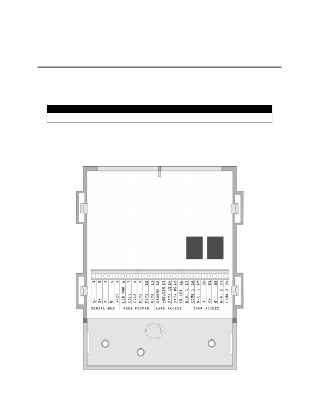
3.1 Model 4421 Installation
Figure 3-1 shows the layout of the 4421 board. Table 3-1 (next page) is a terminal strip
description.
Figure 3-1 Model 4421 Board Layout
150963 3-1
Page 28

Model 4821/4820 Control/Communicator Installation Manual
Table 3-1: Model 4421 Terminal Description
Name
Wire
Color
Terminal Description Electrical Rating
1 S- Expansion Bus (-) 0 VDC (circuit ground)
2 S+ Expansion Bus (+) 12 VDC, 1 Amp max.
3 A Expansion Bus (data) 5 VDC
4 B Expansion Bus (data) 5 VDC
5 +PZT PZT power output 4 VDC, 10 mA
6 LED PWR Brown 4205 LED output 8.3 VDC, 10 mA
7 COL1 Red 4205 column 1 output
8 COL0 Orange 4205 column 0 output
9 KEY2 Yellow 4205 row 4 input
10 KEY1 Green 4205 row 1 input
11 KEY0 Blue 4205 row 0 input
12 GROUND Black &
Circuit Ground
Shield
13
Red Card reader power output 5 VDC, 75 mA
+READER
14 DATA 1s White Card reader data 1’s input
15 DATA 0s Green Card reader data 0’s input
16 CR LED Brown Card reader LED output 3.75 VDC, 25 mA
17 N.O. 1 Relay Contact (Normally Open) #1 2.5 Amps max. @ 24 VDC
18 COMN 1 Relay Contact (Common) #1
19 N.C. 1 Relay Contact (Normally Closed) #1
20 1 Zone Input 1 14 VDC, 1.5 mA
21 C+ Zone power 12 VDC, 3.0 mA
22 2 Zone Input 2 14 VDC, 1.5 mA
23 N.O. 2 Relay Contact (Normally Open) #2 2.5 Amps max. @ 24 VDC
24 COMN 2 Relay Contact (Common) #2
3-2 150963
Page 29
Access Control Installation and Operat ion
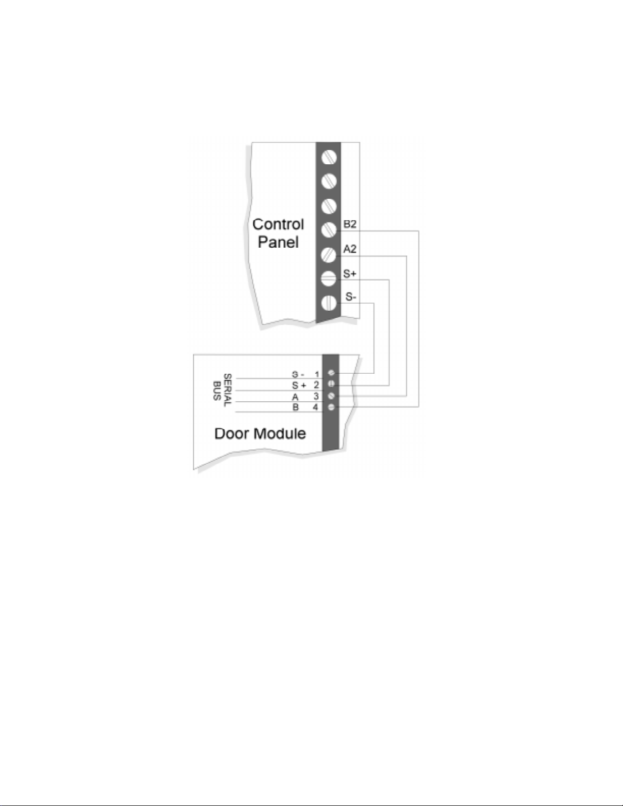
3.1.1 Model 4421 Connection to the 4821
The 4421 Interface connects to the 4821 panel via the SBUS. Connect the 4421 to the panel as
shown in Figure 3-2. See Section 4 for complete information about SBUS device connections.
Figure 3-2 Wiring Diagram 4421of N to the Control Panel
150963 3-3
Page 30
Model 4821/4820 Control/Communicator Installation Manual
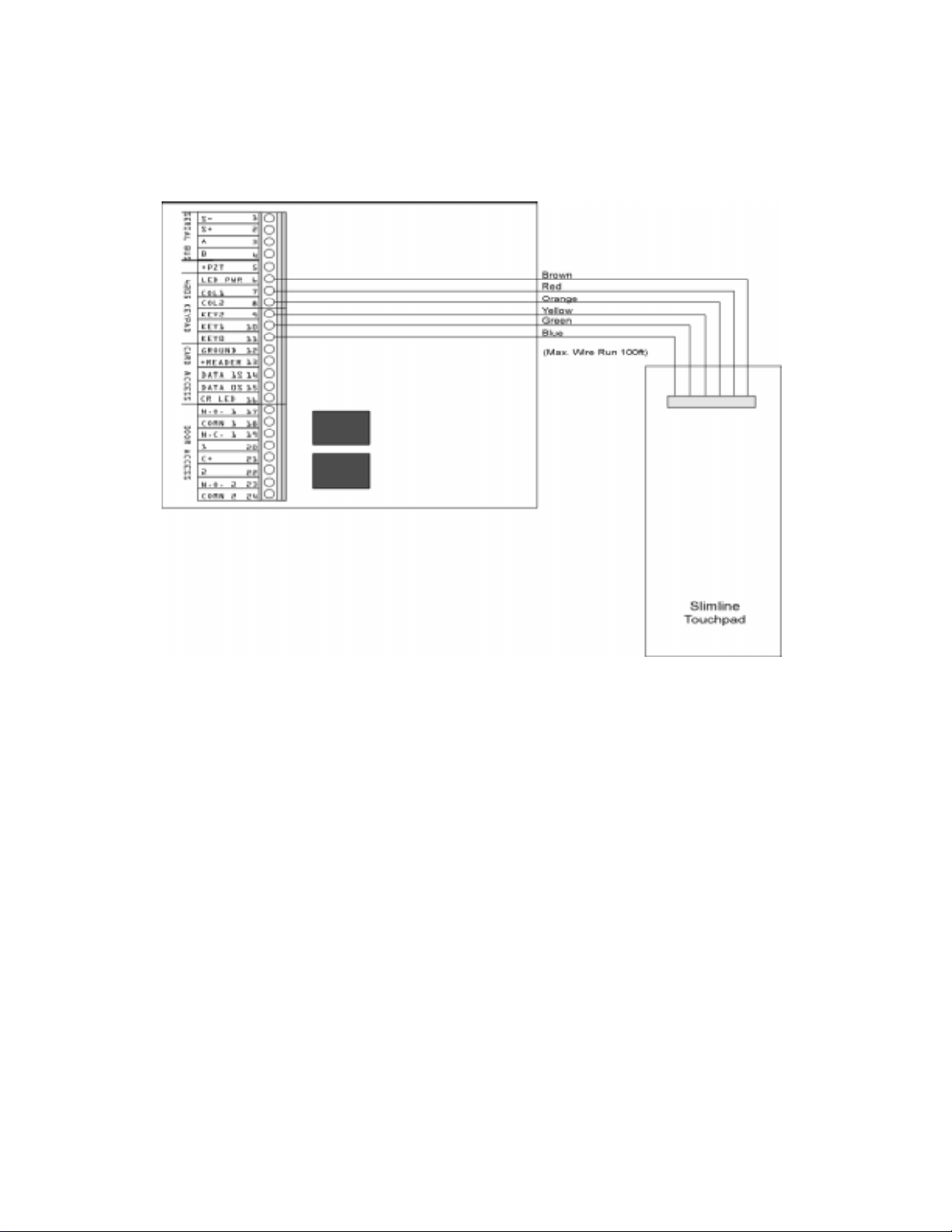
3.1.2 4205 Touchpad Connection to 4421
The 4205 Access Control Touchpad is connected to the 4421 as shown in Figure 3-3.
Figure 3-3 Model 4421 to 4205 Connection
Note: The Model 4205 is not UL listed for access control.
3-4 150963
Page 31

Access Control Installation and Operat ion
3.2 Card/Proximity Reader Installation
The Model 4421 Access Control Interface is compatible with 26-bit (plus a leading and trailing parity bits), 24-bit (plus a start-bit and a trailing parity bit), 32-bit, 34-bit (32 data plus a
start-bit and a trailing parity bit), and 34-bit (32 data plus a leading and trailing parity bit)
Wiegand-format readers. (See Figure Figure 3-4.) The following sections describe how to
install the 4300 series readers. Refer to device manual for other manufacturers’ products.
32 Bit
26 or 34 Bit
Figure 3-4 Block Diagram of Wiegand Formats
3.2.1 Card Reader Specifications
The 4300 Swipe Card Reader, and the 4330, 4340, and 4350 Proximity Readers require
shielded cable. The chart below shows the specifications.
Max. Reader to Receiver
Distance
Gauge Distance
24 AWG
18 AWG
24 AWG
18 AWG
24 AWG
18 AWG
24 AWG
18 AWG
85 m (270’)
137 m (450’)
85 m (270’)
137 m (450’)
85 m (270’)
137 m (450’)
85 m (270’)
137 m (450’)
Model
4300 5 VDC
4330 12 VDC
4340 12 VDC
4350 12 VDC
Supply
Voltage
(+ or -5%)
(+ or -5%)
(+ or -5%)
(+ or -5%)
Max.
Supply
Current
25 mA 48 mA 5 mA
80 mA 48 mA 5 mA
80 mA 48 mA 5 mA
150 mA 48 mA 5 mA
Output
Sink
Output
Source
Current
Output
Pulse
Width
20 µs typ.
20 µs typ.
20µs typ.
20µs typ.
Operating
Temp.
°
-40
to 130° F
-22° to 149° F
°
-22
to 149° F
°
-22
to 149° F
3.2.2 Mounting
Mount the 4300 series readers on any flat vertical surface.
Use two #10 bolts to mount the reader. Once the reader is mounted, cover the reader front by
applying the pressure-sensitive dress panel or label.
When mounting the proximity readers, use flat-head screws. Drill a one-quarter inch (0.6 cm)
or larger hole for the cable. Refer to the mounting template included with the reader for location of screw holes.
150963 3-5
Page 32

Model 4821/4820 Control/Communicator Installation Manual
If the card readers will be in a location where they will be exposed to snow, mount in a vertical position to prevent accumulated snow from clogging the card slot.
3-6 150963
Page 33

Access Control Installation and Operat ion
3.2.3 Wiring the 4300 Swipe Card Reader
Wire the swipe card reader to the 4421 Door Access Module as shown in Figure 3-5. The card
reader LED is on when the door relay is activated. The LED is off when the relay is deactivated or when there is no power. (The 4421 LED has the same meaning.)
Figure 3-5 Model 4421 to 4300 Connection
150963 3-7
Page 34

Model 4821/4820 Control/Communicator Installation Manual
3.2.4 Wiring the 4330, 4340 and 4350 ProximityReaders
Wire the Proximity Reader to the 4421 Door Access Module as shown in Figure 3-6. The card
reader LED is on when the door relay is activated. The LED is off when the relay is deactivated or there is no power. (The 4421 LED has the same meaning.)
Figure 3-6 Model 4330, 4340 and 4350 Connection
3-8 150963
Page 35

Access Control Installation and Operat ion
3.3 Wiring the 4860C Touchpad for Door Access
The 4860C commercial touchpad can be used as a door access station. The zone inputs on the
back of the touchpad can be wired to a door contact or could be used for any other purpose.
*Use Cable Assembly
130375
P/N
*Use Cable Assembly
130378
P/N
Figure 3-7 Wiring the 4860C Touchpad for Door Access
Connecting wires are included with the card readers.
N-750-
150963 3-9
Page 36

Model 4821/4820 Control/Communicator Installation Manual
ENTR
Table 3-2: Connector Descriptions
P2 (Card Reader) P4 (Door Access)
Pin
Number
1 Circuit Ground Black 1 C+ is +12V Brown
2 LED Brown 2 Zone Input 1 Red
3 Data 0’s Green 3 Relay Contact
4 Data 1’s White 4 Relay Contact
5 +5 VDC Red 5 Relay Contact
Description
(P/N 130375)
Wire Color
Pin
Number
6 Not used Blue
7 Zone Input 2 Violet
8 C+ is +12V Gray
Description
(Common)
(Normally Open)
(Normally Closed)
(P/N 130378)
Wire Color
Orange
Yellow
Green
3.4 Access Control Operation
This section of the manual describes operation of access control features. An overview of
these operations is included in the Operations Summary in Section 5 of this manual.
3.4.1 Access Control Touchpad Menus
DOOR BYPS DOOR ENTR
The
The
DOOR BYPS
Section 3.4.3 for more information). The
passback status (see Section 3.4.6). A brief summary of end-user operations are in section
3.4.2.
and
menu is for controlling door lock/unlock schedules from the touchpad (see
menus are for maintenance level access control operations.
DOOR
menu is for controlling users’ anti-
3-10 150963
Page 37

Access Control Installation and Operat ion
3.4.2 End-User Operation
Normal end-user door access operation (accessing a door, opening an outside door from
within, and so on) are described in the Census 4821 Owner’s Manual (P/N 150952). They are
summarized below:
Opening an access controlled door Present your card to the card reader. You will hear a c lick and the red
LED will turn green indicating that the door can be opened.
OR
DOOR
Press plus your PIN.
Opening an access controlled door for
another person (granting access)
Opening a high security door High security doors are used to secure areas within an installation
This operation would apply at a door station where a receptionist,
security guard, or other person “buzzes in” another person after
identification.
DOOR
Enter the device ID number of the door, then press
PIN. You may hear a click or buzzing sound indicating that the door
can be opened.
that not all employees are allowed to access. Both a card
are required to gain access.
Present your card. The touchpad will display
your PIN.
ENTER CODE
and your
and
a PIN
. Enter
150963 3-11
Page 38

Model 4821/4820 Control/Communicator Installation Manual
3.4.3 Manually Changing Door Schedules
DOOR BYPS
The menu is for changing door access schedules from the touchpad. You can use
this feature to temporarily override door schedules. Any operations made using the touchpad
will be overridden the next time the schedule for the door takes effect.
• From the touchpad assigned to the current door, press, [Maintenance or
DOOR BYPS
Installer’s Code]. The status of the door will display for a few seconds then a menu with
the options shown in the chart below will begin scrolling.
•From any touchpad, enter the device number of the door,
Installer’s Code]. For example, to access Door #4, press [Maintenance or
DOOR BYPS
4 DOOR BYPS
[Maintenance or
Installer’s Code].
The status of the door will display for a few seconds then a menu with the options shown in
the chart below will begin scrolling.
0 - Unlock Door Unlocks the door until the next scheduled lock time. Use this option to unlock a door
that is currently scheduled to be locked. All users will be able to access the door.
9 - Lock Door Locks the door until the next scheduled unlock time. Use this option to lock a door
that is currently scheduled to be unlocked. No users will be able to access the door
without a card or a code.
1 - To Sched Restores the selected door to its scheduled setting.
2 - All Sched Restore all door s to their scheduled settings.
3 - All Locked Lock all doors. Overrides all door schedules.
4 - Select Door Select another door to lock or unlock.
5 - Access Door Open a door to allow individual access (not the same as unlocking).
STAT - STATUS View the status of the door.
3.4.4 Viewing Door Status
Press to view the door status. A list of doors and their locked/unlocked status
displays.
3-12 150963
DOOR STAT
Page 39

Access Control Installation and Operat ion
3.4.5 Anti-Passback Feature
The anti-passback feature prevents users from giving access to others by “passing back” their
access cards. In a typical anti-passback installation, users must “register” themselves by
accessing a door programmed as Entry when they enter the building. They will only be
allowed to leave from a door programmed as Exit. A user cannot access an Entry door twice
consecutively. The menu allows users to be “forgiven” (allowed access even if
they have not exited properly) and provides other anti-passback options. See Section 3.4.6.
Figure 3-8 below shows an example of anti-passback application. In this example, employees
enter through an anti-passback doors (must enter and exit through separate doors). The manager’s entrance is not an anti-passback door, allowing employees to come and go freely.
Note: The anti-passback feature must be enabled through programming. See Section 6.
DOOR ENTR
Figure 3-8 Sample Anti-Passback Application
150963 3-13
Page 40

Model 4821/4820 Control/Communicator Installation Manual
3.4.6 Anti-Passback Operations
DOOR ENTR
The menu is for controlling the anti-passback feature. It allows you to change
users’ anti-passback status so that they can access or be prevented from accessing the system.
When you press [Maintenance or Installer’s Code], the following menu options
DOOR ENTR
display.
1 - User Status Use to check the user’s current status (for example, In or Out).
2 - Forgive Forgive means allow the user to enter or exit a door even though the system has
detected a problem with the users’ anti-passback status.
3 - Lockout User Change the user’s status so he or she will be unable to enter the building.
4 - Num User In Use this option to see how many users have “In” status.
5 - Forgive All Reset anti-passback status and allow all users to enter the next time they attempt.
MUTE - Exit Press to exit the menu.
3.4.7 Bulk Loading Access Cards
Bulk loading of access card allows you to enter multiple successive access cards in one procedure. Follow these steps to bulk load access cards:
1. This can be done by pressing .
7 ENTR
The display on the touchpad will read:
(OUFS 6FMFDUJPO (OUFS 6FMFDUJPO
&IBOHF VTFST
2. Press then enter the user ID you wish to start with followed by .
2 ENTR
(then)
%VML MPBE
The display on the touchpad will read:
3SPGJMF
3. When prompted, enter a profile number followed by the key.
ENTR
The display on the touchpad will read:
&BSE GPS ,E ;;;;
Note: XXXX equals the number entered in step 2.
4. Present a valid access card to the card reader.
The access card will be added to the syste m imm ediate ly followed by a success be ep. The
user ID will increase by one.
Note: If the card is already in the system, a failure beep sounds and you are taken back to step 2.
5. Repeat step 4 until all access cards are presented.
3-14 150963
Page 41

Access Control Installation and Operat ion
3.5 Egress Fail-safe Override Application
An egress fail-safe override is an optional configuration that can be used to give the installation an additional means of exit through access controlled doors in the case of power loss or a
system failure.
Use the following diagrams to configure your system for egress fail-safe override.
Note: In each of the diagrams the egress device can be a motion detector, a crash bar, a button, a beam, etc.
Figure 3-9 Fail-safe Override N.C. Configuration to a Door Access Module
150963 3-15
Page 42

Model 4821/4820 Control/Communicator Installation Manual
Note: Input 1 must be programmed for “Not re ady” on short.
Figure 3-10 Fail-safe Override N.O. Configuration to a Door Access Module
3-16 150963
Page 43

Access Control Installation and Operat ion
Figure 3-11 Fail-safe Override N.C. Configuration to a Touchpad
Figure 3-12 Fail-safe Override N.O. Configuration to a Touchpad
150963 3-17
Page 44

Model 4821/4820 Control/Communicator Installation Manual
3-18 150963
Page 45

Section 4
Control Panel Description and Installation
Warning:
To avoid the risk of electrical shock, do not apply power to the Model 4821/4820 until
you have read these instructions carefully.
This section describes how to install the control panel and some accessories, including compatible add-on modules, such as smoke detectors and signaling devices. In all cases, refer to
the compatible module’s installation manual for complete information. (Some Silent Knight
compatible modules have separate installation manuals. See Section 1.1.1 for location of
installation instructions for Silent Knight products.)
4.1 Environmental Specifications
• Temperature range is 32° to 120° F (0° to 49° C).
• Indoor use only.
• 85 percent non-condensing humidity.
• Non-corrosive environment.
4.2 Electrical Specifications
Line voltage: 110-120 VAC, 60 Hz
Transformer output:
(Model 9227)
Current requirements: 3.0A
Total alarm current: 2.25A
IMPORTANT!
All circuits are power limited, Class II, except for the battery leads.
18 VAC, 50 VA
150964 4-1
Page 46

Model 4821/4820 Control/Communicator Installation Manual
4.3 Board Layout
Figure 4-1 shows the Model 4821/4820 printed circuit board.
Figure 4-1 Model 4821/4820 Printed Circuit Board
4-2 150964
Page 47

Control Panel Description an d Installation
4.4 Terminal Strip Description
Table 4-1: Control Panel Terminal Descriptions
Name Terminal Description Electrical Ratings
AC AC Input 18 VAC, 60 Hz, 50VA
AC AC Input 18 VAC, 60 Hz, 50VA
EARTH Earth Ground 0 VDC
N.O. Relay Contact (Normally Open) 2.5 Amps max. @ 24VDC
COM Relay Contact (Common)
+12V Accessory Power (+) 12 VDC, 1 Amp max.
+SMK Smoke Detector Power (+) 12 VDC, 1 Amp max.
GND Circuit Ground 0 VDC
EXT SPK External Speaker (+) 8 ohm, 15 watt min. rating speaker output
INT1 SPK- Internal Speaker #1 (-)
INT+ Internal Speaker (+) (1) 8 ohm, 5 watt, or (3) 45 ohm, 1 watt
INT2 SPK- Internal Speaker #2 (-)
Must be connected to power limited sources only
S2- SBUS #2 (-) 0 VDC
S2+ SBUS #2 (+) 12 VDC, 1 Amp max.
A2 SBUS #2 (data) 5 VDC
B2 SBUS #2 (data) 5 VDC
S1- SBUS #1 (-) 0 VDC
S1+ SBUS #1 (+) 12 VDC, 1 Amp max.
A1 SBUS #1 (data) 5 VDC
B1 SBUS #1 (data) 5 VDC
1 Zone 1 Input 12 VDC, 50mA max.
.079 VDC Nominal
(Note that this zone is rated differently from other
inputs.)
C+ Zones 1 and 2 Power Output All zone power outputs: 12 VDC
Use ESL Model 449CT 4-wire smoke detector.
150964 4-3
Page 48

Model 4821/4820 Control/Communicator Installation Manual
Table 4-1: Control Panel Terminal Descriptions
Name Terminal Description Electrical Ratings
2 Zone 2 Input For zone 2-16 inputs:
3 Zone 3 Input
C+ Zones 3 and 4 Power Output
4 Zone 4 Input
5 Zone 5 Input
C+ Zones 5 and 6 Power Output
6 Zone 6 Input
7 Zone 7 Input
C+ Zones 7 and 8 Power Output
8 Zone 8 Input
9 Zone 9 Input
C+ Zones 9 and 10 Power Output
10 Zone 10 Input
12 VDC max. at 1.4 mA
11 Zone 1 1 Inp ut
C+ Zones 11 and 12 Power Output
12 Zone 12 Input
13 Zone 13 Input
C+ Zones 13 and 14 Power Output
14 Zone 14 Input
15 Zone 15 Input
C+ Zones 15 and 16 Power Output
16 Zone 16 Input
T-RING Telco Ring
T-TIP Telco Tip
P-RING Premises Ring
P-TIP Premises Tip
4.5 Power Limitin g Ci rcuits
The Model 4821/4820 is power-limited for over-current protection. When you remove the
short, circuits self-restore.
4-4 150964
Page 49

Control Panel Description an d Installation
4.6 Power Switch
The power switch is disabled by the power switch bypass jumpers, to enable the power switch
cut both jumpers. Make sure the power switch is off when you are installing the system. See
Figure 4-1 for location of the power switch and power switch bypass jumpers.
Note: The power switch bypass jumpers can not be cut for UL 864 and NFPA (Chapter 4) fire installations. (See
Section 1.4.3.5.)
4.7 Mounting the Model 4821/4820 Panel
When selecting a location to mount the Model 4821/4820, consider the following:
• Panel must be accessible to main drop wiring runs.
• Panel must be located well within the secured area, but must be accessible for testing and
service.
• See environmental specifications described in Section 4.1.
If you are installing a UL Grade A Mercantile installation, all unused knockout holes must be
plugged using bolts and washers. (Model 7600 is a kit available from Silent Knight for this
purpose. 6 sets per package.) Use the following steps to plug the knockout holes:
1. Remove all unused knockouts.
2. Install the carriage bolt and washers as shown in the diagram below. The smallest washer
should be placed
inside
the hole in the cabinet.
3. Firmly tighten the wing nut.
CABINET
CARRIAGE
BOLT
LARGE
WASHER
SMALL
WASHER
KNOCKOUT HOLE
Figure 4-2 Knockout Plug Installation
LARGE
WASHER
WING
NUT
150964 4-5
Page 50

Model 4821/4820 Control/Communicator Installation Manual
4.8 Wire Routing
Figure 4-3 is an example of how Model 4821/4820 wires should be routed through the cabinet
in order to maintain one-quarter inch spacing between power limited and non-power limited
circuits.
Figure 4-3 Sample Wire Routing
4-6 150964
Page 51

Control Panel Description an d Installation
4.9 Current Draw Worksheets
The current draw worksheets in this section are provided to help you calculate the number and
size of devices that will be used in an installation. Copy these sheets as needed.
Figure 4-4 and Figure 4-5 are sample worksheets. (They have already been filled out to serve
as examples.) Blank worksheets for your installations are in Sections 4.9.2 and 4.9.3.
4.9.1 Sample Worksheets
Figure 4-4 Sample Silent Knight Module Current Worksheet
150964 4-7
Page 52

Model 4821/4820 Control/Communicator Installation Manual
Figure 4-5 Sample Compatible Module Current Worksheet
4-8 150964
Page 53

Control Panel Description an d Installation
4.9.2 Worksheet for Silent Knight Modules
Table 4-2: Current Draw Worksheet for Optional Modules
Device
Model 4821/4820 Control/
Communicator
4421 Door Access Module
4860 Series Touchpad
4205 Touchpad (used with
the 4421)
4880 Status Output Module
4824 Serial/Parallel Interface
4815 Zone Expander
4825 Zone Expander
4875 Dual Phone Line
Monitor
4884 Bell Module
4300 Swipe Card Reader
4330 Proximity Reader
4340 Proximity Reader
4350 Proximity Reader
5211 Ground Start Relay
Number of
Devices
1 Standby: 100 mA 100 mA
(1 max.) Alarm: 120 mA 120 mA
(24 max.) Alarm 40 mA mA
(24 max.) Alarm: 90 mA mA
(24 max.) Alarm: 10 mA mA
(3 max.) Alarm: 140 mA mA
(8 max.) Alarm: 40 mA mA
(3 max.) Alarm: 80 mA mA
(6 max.) Alarm: 80 mA mA
1 Standby: 0 mA mA
(1 max.) Alarm: 18 mA mA
1 Standby: 5 mA mA
(1 max.) Alarm: 60 mA mA
(24 max.) Alarm: 25 mA mA
(24 max.) Active: 80 mA mA
(24 max.) Active: 80 mA mA
(24 max.) Active: 150 mA mA
1 Standby: 0 mA mA
(1 max.) Alarm: 18 mA mA
Current per Device
Standby 25 mA mA
Standby: 48 mA mA
Standby: 10 mA mA
Standby: 20 mA mA
Standby: 40 mA mA
Standby: 80 mA mA
Standby: 80 mA mA
Standby: 25 mA mA
Standby: 45 mA mA
Standby: 45 mA mA
Standby: 100 mA mA
Subtotal of current rati ngs for Silent Knight devices
Total
Standby
Current
mA
Standby
Total Alarm
Current
mA
Alarm
Note: Total of all 4421s and 4860s combined.
Note: The 4884 shares its power wi th the auxiliary output. The auxiliary output is rated at 1A total current for
all devices.
150964 4-9
Page 54

Model 4821/4820 Control/Communicator Installation Manual
4.9.3 Worksheet for Auxiliary Devices (not Silent Knight)
Use Table 4-3 for recording current draw for other devices compatible with the 4821/4820
that are not manufactured by Silent Knight (for example, signaling devices and smoke detectors). Copy this page if you need additional lines to list devices.
Table 4-3: Current Draw Worksheet for Other Devices
Row B
Number of
Device
Smoke Detectors
Signaling Dev i ces
Other Devices
Devices Current per Device
Refer to device manual for current ratings.
Standby: mA mA
Alarm: mA mA
Standby: mA mA
Alarm: mA mA
Standby: mA mA
Alarm: mA mA
Standby: mA mA
Alarm: mA mA
Standby: mA mA
Alarm: mA mA
Refer to device manual for alarm current ratings. Standby current is always 0 mA.
Alarm: mA
Alarm: mA mA
Alarm: mA mA
Alarm: mA mA
Refer to device manual for current ratings.
Standby: mA mA
Alarm: mA mA
Standby: mA mA
Alarm: mA mA
Standby: mA mA
Alarm: mA mA
Subtotal current ratings of all devices in Table 4-3.
Total
Standby
Current
mA
Standby
Total Alarm
Current
mA
mA
Alarm
Row A
Row C
Subtotal current ratings of SK devices from Table 4-2.
Total current ratings of all devices in system (Row A + Row B)
mA
Standby
mA
Standby
Alarm
Alarm
4-10 150964
mA
mA
Page 55

Control Panel Description an d Installation
4.9.4 Battery Calculation Worksheet
To ensure 24-hour standby, the total standby current must not exceed:
285 mA if a battery only is used.
450 mA if the Model 4195 Auxiliary Power Supply is used.
Total alarm current must not exceed 2.25 Amps.
Table 4-4: Battery Calculation Worksheet
Device
A
B
C Number of standby hours (for example, 24) H
D Multiply lines B and C AH
E
F Multiply lines B and E AH
G Add lines D and F AH
H
Total current used by 4821/4820
(from Table 4-3, Row C)
Total current ratings converted to amperes
(Line A x .001)
Alarm sounding period in hours
(For example, 5 minutes = .084 hours)
Multiply line G by 1.2
(T o tal ampere hou rs requ ired)
Standby
Current
mA mA
AA
AH
Alarm
Current
H
4.9.5 Standby Current For DACT Compliant Installations
In order to meet the 24-hour standby requirement the total standby current Must Not exceed
475mA for the system using both the 4821/4820 Control Panel and the 4195 Auxiliary Power
Supply. The combination of these supplies provides 14 amp hours of standby power.
If your system configuration exceeds 475 mA of standby current you must provide additional
power from an external power supply. Silent Knight has tested the following power supplies
for compatibility with the 4821/4820 Control Panel:
• Alarm Saf Model PS5-BFS-12-UL
• Altronix Model AL400ULX
150964 4-11
Page 56

Model 4821/4820 Control/Communicator Installation Manual
4.10 AC Power Transformer
The Model 9227 is an external transformer that is included with the 4821/4820. The transformer output is 18 VAC, 50VA and provides power and battery charging for the system. The
transformer plugs directly into a conventional 120 VAC unswitched outlet.
The earth terminal on the 4821/4820 main circuit board provides a convenient method for
connecting the 4821/4820 metal cabinet to an earth ground. (See Figure 4-6.)The earth connection is also used for increased transient protection on the telephone interface. All circuitry
in the Model 4821/4820 system is electrically isolated from this earth terminal on the 4821/
4820 main circuit board. There should be no connections to this terminal other than the earth
connection for grounding the metal cabinet.
Figure 4-6 Model 9227 Connection to Model 4821/4820
4-12 150964
Page 57

Control Panel Description an d Installation
4.11 Backup Battery Connection
The Model 6712 is a 12 VDC 7AH gell cell battery available from Silent Knight for use with
the 4821/4820. (Note that the battery does not charge when system power is off.)
A low battery trouble condition exists if the battery voltage drops below 10.2 VDC.
The nominal charging voltage is 13.65 VDC (range is 13.5 to 14.0).
This manual contains a worksheet for determining battery size. See Section 4.9.4 for more
information.
Note: If you are installing a battery in a system that has a tamper switch, an alarm may occur when you install
the battery (because the door must be open when power is applied).
Figure 4-7 Model 6712 Battery Connection
150964 4-13
Page 58

Model 4821/4820 Control/Communicator Installation Manual
4.12 4195 Auxiliary Power Supply Installation
Through its two 1.25A 12 VDC terminals, the 4195 provides an additional 2.5A of current for
accessory items. The 4195 also allows you to use two standby batteries to double t he time that
the system can function on battery standby.
Figure 4-8 shows the location of LEDs for battery reversal and output overload. It also shows
how to wire the 4195. If you are using the 4195 to power smoke detectors, connect the 4195
CONTROL terminal to the 4821/4820 +SMK terminal. For powering other types of devices,
connect CONTROL to +12V.
Figure 4-8 Model 4195 Auxiliary Power Supply Connection
4-14 150964
Page 59

Control Panel Description an d Installation
4.13 SBUS
Most modules available for use with the 4821/4820 connect via a four-wire serial bus (SBUS).
There are two SBUS connections that are referred to in this manual as “SBUS1” and
“SBUS2”.
Each SBUS is a four-wire serial bus containing two power and two data conductors. The
power conductors are identified as S- (system ground) and S+ (+10 to +14 volts). The data
conductors are identified as A and B. Lines A and B are a differential RS485 pair.
All modules connected on the SBUS can be located as far as 4,000 feet from the control panel,
if sufficiently large wire gauges are used for the power and ground connections. The voltage
drop on the wire run must not be more than 2.0 volts. (See Section 4.13.3 for specifics.)
Figure 4-9 is a general picture of SBUS connection points. Wiring for each SBUS module is
shown in the appropriate section of this manual or in the separate manual for the device.
Figure 4-9 SBUS Connection Points
4.13.1 SBUS Modules
The following modules connect to the 4821/4820 via the SBUS:
• Touchpads (Models 4421, 4860C, 4860R, and 4860Rx)
Note: 4421 cannot be used with the 4820 control panel
• Zone Expanders (Models 4815 and 4825)
• Status Output Module (Model 4880N-750-SDB)
• Serial/Parallel Module (Model 4824)
Figure 4-10 shows an installation making use of all SBUS modules available with the Model
4821/4820 system. (For simplicity, the diagram shows all modules connected to a single
SBUS, though in a real application you would typically divide modules as evenly as possible
between SBUS1 and SBUS2.)
150964 4-15
Page 60

Model 4821/4820 Control/Communicator Installation Manual
4.13.2 Distribution of Modules Between SBUS1 and SBUS2
SBUS modules can be distributed between the two serial buses in any combination.
Note: In a UL installation, each SBUS must have at least one touchpad.
Figure 4-10 Sample SBUS Connections
4-16 150964
Page 61

Control Panel Description an d Installation
4.13.3 Number of SBUS Devices
The table below shows the maximum number of devices and maximum distance from the
4821/4820 for SBUS devices, assuming a maximum of 2 volts of line drop and 100 mA of
current per device. Following these guidelines guarantees that there will be sufficient voltage
in the worst case (when the battery voltage is 10V or greater and when all devices are located
at the end of the wiring). (The formula used to generate this table is shown in the note below.)
Table 4-5: Number of SBUS Devices
Model 4821/4820 to SBUS Devices
Maximum wiring distance with 14 - 22 gauge wire (AWG)
Num. of Devices
per 4-Conductor Wire 22 Gauge 18 Gauge 16 Gauge 14 Gauge
1 617 ft. 1562 ft. 2487 ft. 3937 ft.
Max. distance for all
home-run devices.
2 308 ft. 781 ft. 1243 ft. 1968 ft.
Max. distance for 2 T-
tapped or daisy-chained
devices.
3 205 ft. 520 ft. 829 ft. 1312 ft.
Max. distance for 3 T-
tapped or daisy-chained
devices.
4 154 ft. 390 ft. 621 ft. 904 ft.
Max. distance for 4 T-
tapped or daisy-chained
devices.
Note: The following formula was used to calculate the maximum wire distances:
Max. Distance = 500V
NIRpu
where: V = 2 volts (Maximum allowed voltage drop under low battery condition of 10.0
volts.)
N = Number of devices
I = .1 amps (Worst case current draw for all devices.)
Rpu = Ohms per 1,000 feet for various wire gauges, see below.
Wire gauge
22
18
16
14
Ohms per 1,000 feet
16.2
Ω
6.4
Ω
4.02
Ω
2.54
Ω
150964 4-17
Page 62

Model 4821/4820 Control/Communicator Installation Manual
4.14 Touchpad Installation
This section describes installation of a touchpad for basic system operation. For information
about how to install 4860C touchpads as input zones, see Section 4.15.5.
4.14.1 Touchpad Specifications
• When installed for use as an access control system the touchpad must be located inside the
protected premises.
• 24 touchpads/card readers maximum per system.
• All touchpads require four wires to operate.
• Maximum distance from the control panel depends on the number of devices attached to
the SBUS. See Section 4.13.3 for complete information.
• Maximum current draw: 90 mA
• Standby current draw: 48 mA
• Maximum allowed voltage drop for a touchpad wire run: 2V
• For best system performance, connect most touchpads to the same SBUS, either SBUS1
or SBUS2. (Connect all other SBUS devices to the SBUS that is not used by touchpads.)
4.14.2 Mounting Touchpads
1. Separate the top section from the rear mounting plate. Do this by inserting a small flatblade screwdriver into the slot located on the bottom edge of the frame. (See Figure 4-11.)
Push in, then lift up the top section.
Figure 4-11 Mounting Plate Slot location.
2. Secure the mounting plate to the wall using the screw (#6 or #8) appropriate for the type of
wall material.
3. The mounting plate should be oriented so that the protruding tab and the three posts are
towards the bottom. Pull the wires through the hole in the rear mounting plate.
4-18 150964
Page 63

Control Panel Description an d Installation
4. Wire the touchpad as described in Section 4.14.3.
5. After all the wires are connected to the touchpad terminal strip, set the top of the touchpad
frame over the tabs at the top of the mounting plate, then press on the bottom until you
hear it snap into position.
4.14.3 Wiring Touchpads
Figure 4-12 shows how to connect a Model 4860 touchpad to the 4821/4820.
Figure 4-12 Touchpad Wiring
150964 4-19
Page 64

Model 4821/4820 Control/Communicator Installation Manual
4.15 Zone Installation
4.15.1 Zone Hardware Specifications
The chart below lists all input zone hardware types available with the 4821/4820 modules.
Hardware Module Description
4821/4820 16 internal zones are built into the 4821/4820 main system board.
4825 Hardwire Zone Expander Each 4825 adds up to 64 hardwire zones. These zones have all the same
features as 4821/4820 internal zones.
4815 Serial Zone Expander Each 4815 adds up to 128 serial SmartSensor zones. The differences
between the SmartSensor zones and all other zones used in the 4821 /4820
system are described in detail in the 4815 tabbed section of this binder
(part number 150909).
4860C Touchpad Zones Two input zones are built into the 4860C touchpads. These zones have all
the same features as 4821/4820 internal zones (except that the fastest
response speed, 10 milliseconds) is not available. The installation is the
same as the 4821/4820 internal zones. See Sections 4.15.5 and 4.15.6.
Note: 4421 cannot be used wi th
the 4820 control panel.
4421 Door Access Module
Two input zones are built into the 4421. These zones have all the same
features as 4821/4820 internal zones (except that the fastest response
speed, 10 milliseconds) is not available. The installation is the same as the
4821/4820 internal zones.
4.15.2 Maximum Number of Zones per System
The maximum number of zones that can be connected to the 4821/4820 is 400.
These zones can be a combination of internal zones, 4815, 4825, 4421, and 4860C touchpad
zones.
4-20 150964
Page 65

Control Panel Description an d Installation
4.15.3 Zone Configuration
At any moment an input zone can be in one (and only one) of three states, depending on the
state of the hardware circuit connected to the zone input. The possible states are Open Circuit,
EOL Circuit, and Short Circuit. The value of the EOL resistor used on all input zones in the
4821/4820 system is 4.7k ohms (Silent Knight part number 7628). 4815 SmartSensor zones
are an exception because they require a 1.43k ohm resistor (Silent Knight model 4114).
Note: UL zones must be end-of-line supervised.
Figure 4-13 Zone States
Through programming, you determine how the zone will respond to the three possible states
when it is armed and disarmed. The possible system responses for all three states are Ready,
Not Ready, Trouble, or Alarm. See Section 4.15.4 for examples of typical zone wiring.
150964 4-21
Page 66

Model 4821/4820 Control/Communicator Installation Manual
4.15.4 Zone Configuration Examples
The chart below shows some commonly used zone hardware configurations and provides
examples of how you might want to program the zone for the disarmed and armed responses.
UL zones must be end-of-line supervised.
State of Zone
Open Circuit
Contact open or open hardware fault.
EOL Circuit
(This state is not possible
for this example, but you
still must program a system response for this configuration.)
Short Circuit
Contact closed or shorted
hardwar e fault.
Open Circuit
Contact open or open hardware fault.
EOL Circuit
(This state is not possible
for this example, but you
still must program a system response for this configuration.)
Short Circuit
Contact closed or shorted
hardwar e fault.
Programmed
Disarmed Response
Ready Ready
Not Ready Alarm
Not Ready Alarm
Not Ready Alarm
Not Ready Alarm
Ready Ready
Programmed
Armed Response
4-22 150964
Page 67

Control Panel Description an d Installation
State of Zone
Open Circuit
Open circuit hardware
fault.
EOL Circuit
The contact is open and supervised.
Short Circuit
The contact is closed or
there is a short circuit hardware fault.
Open Circuit
The contact is open or
there is an open circuit
hardwar e fault.
EOL Circuit
The contact is closed and
supervised.
Short Circuit
Short circuit hardware
fault.
Programmed
Disarmed Response
Trouble Trouble
Ready Ready
Alarm Alarm
Not Ready Alarm
Ready Ready
Trouble Alarm
Programmed
Armed Response
150964 4-23
Page 68

Model 4821/4820 Control/Communicator Installation Manual
State of Zone
Open Circuit
Open hardware fault or the
N.C. contact is open.
EOL Circuit
The N.C. contact is closed
and the N.O. contact is
open.
Short Circuit
Both contacts are closed or
there is a shorted hardware
fault.
Programmed
Disarmed Response
Not Ready Alarm
Ready Ready
Trouble Alarm
Programmed
Armed Response
4.15.5 Wiring a 4860C as an Input Zone
Figure 4-14 is a back view of the 4860C touchpad showing the location of its two input zones.
These zones are wired and programmed the same as hardwire zones. See Section 4.15.6 for
available zone response speeds.
*Use Cable Assembly
P/N 130378N-750-INPT-
Figure 4-14 Location of 4860C Input Zones
4-24 150964
Page 69

Control Panel Description an d Installation
4.15.6 Zone Response (Debounce) Speed
Through programming, you select the zone response speed for the type of hardware you are
installing. The chart below shows the response (debounce) speeds available. The very fast rate
of 10 milliseconds (needed for devices such as audio glass break detectors) is available only
for internal or 4825 type zones. See Section 6 of this manual for details about how to make
selections for zone options.
Response Speed Available with:
Internal
(Built into
4821/4820
board)
10 milliseconds
(9-18 msec)
100 milliseconds
(55 - 100 msec)
250 milliseconds
(220 - 330 msec)
1 second
(0.5 - 1.0 seconds)
10 seconds
(5 - 10 seconds)
Do not use with smoke
verification zones. See
Section 6.3.2.3.
Note: In the Response Speed column above, the range of numbers in parentheses shows the duration (millisec-
onds or seconds) that the zo ne response spee d represents. Th e larger number is the minimum duration that
the zone must remain in a changed state in order for the change to always be recognized by the system. The
smaller number is the maximum dura t ion t hat the zo ne can be i n a cha nged state in order to
nized by the system.
Yes Yes No No
Yes Yes No Yes
No No Yes No
Yes Yes Yes Yes
Yes Yes Yes Yes
4825
(Hardwire
Expansion
Zones)
4815
(Serial
Expansion
Zones)
4860C & 4421
(Touchpad
Zones)
be recog-
not
Example: 10 msec Response Speed
If the zone change of state lasts: The zone state change is:
longer than 18 msec ALWAYS recognized
shorter than 9 msec NEVER recognized
between 9-18 msec might be recognized, but NOT GUARANTEED
150964 4-25
Page 70

Model 4821/4820 Control/Communicator Installation Manual
4.16 Smoke Detector Wiring and Operation
Note: The Model 4821/4820 is not compatible with 2-wire smoke detectors.
4.16.1 Smoke Detector Compatibility
This section describes the 4821/4820 reset and smoke verification cycles. Any smoke detectors attached to the 4821/4820 must be compatible with the reset cycle. If you are using the
smoke verification feature, smoke detectors must also be compatible with the smoke verification cycle. See Section 4.16.1.1 for information about reset operation. See Section 6.3.2.3 for
information about programming the smoke verification option.
4.16.1.1 Smoke Reset Cycle
When you reset a smoke detector, power is off for 6 seconds. The system then applies a restart
time of 36 seconds. During the restart time, smoke power is reapplied and the zones are
allowed to stabilize. The system will not respond to fire zones during the reset period (but will
respond to other types of zones, including fire contact zones).
4.16.1.2 Smoke Verification Cycle
Smoke verification is a four-period cycle:
• Retard Period 18 second delay after a zone is tripped before smoke detector power
turns off.
• Reset Period Smoke detector power is off for 6 seconds.
• Restart Period 36 seconds for the smoke detectors to stabilize. The system will not
respond to fire zones during this time (but will respond to other
types of zones, including fire contact zones).
• Confirmation Period 60 second period during which all zones will be considered instant.
If the zone trips a second time during this period, the zone will go
into alarm immediately.
Smoke verification will not occur if any fire zones are currently in alarm anywhere in the
same partition.
Note: Smoke verification is not compatible with the 10 second zone response (debounce) speed. See Section
6.3.2.3 for more informat ion.
4-26 150964
Page 71

Control Panel Description an d Installation
4.16.2 Four-Wire Smoke Detector Wiring
Figure 4-15 shows how to wire one 4-wire smoke detector to the system. Figure 4-16 shows
how to wire multiple 4-wire smoke detectors.
Model 7628
Silent Knight
Model 160150
Relay Supervision
Module
EOL Resistor
Figure 4-15 Four-wire smoke detector wiring
Model 7628
EOL Resistor
Silent Knight
Model 160150
Relay Supervision
Module
Figure 4-16 Four-wire smoke detectors
150964 4-27
Page 72

Model 4821/4820 Control/Communicator Installation Manual
4.17 Speaker Wiring
The 4821/4820 can be used with one external and two internal speaker outputs. In UL installations, a bell must be the primary source for alarm annunciation in UL burglary installations. In
UL burglary installations speakers can be used as an supplementary source only and are not
intended to be used for evacuation purposes.
4.17.1 Internal Speaker Wiring
Each internal speaker output can accept one 8 ohm, 5 watt speaker or three 45-ohm, 1 watt
speakers in parallel.
Figure 4-17 Internal Speaker Wiring
4.17.2 External Speaker Wiring
The external speaker output can accept one 8 ohm, 15 watt minimum speaker.
Figure 4-18 External Speaker Wiring
4-28 150964
Page 73

Control Panel Description an d Installation
4.18 Bell Wiring
A bell can be attached to the built-in relay on the 4821/4820 and is factory-programmed for
this purpose. A programmable I/O script drives the relay. The script must not be deleted. See
the Model 5580 Download Software Installation and Operation Manual (P/N 150925) for
information about how to select the script.
4.18.1 Residential Type Bell Wiring
The configuration shown in Figure 4-19 is for residential use.
Figure 4-19 Bell Wiring for Residential Use
150964 4-29
Page 74

Model 4821/4820 Control/Communicator Installation Manual
4.18.2 Commercial Bell Wiring
A bell can be attached to the built-in relay on the 4821/4820 and is factory-programmed for
this purpose. If you are installing a UL commercial burglary system, you must use an Ademco
AB12 Bell and Box bell and enclosure. Wire as shown in Figure 4-20.
Figure 4-20 Commercial Bell Wiring
4-30 150964
Page 75

Control Panel Description an d Installation
4.19 4884 Bell Module wiring
The 4884 is plugged directly onto the P2 connector on the 4821/4820 Control Panel. (Refer to
Figure 4-21 for placement of 4884 Bell Module on P2 connector.)
Figure 4-21 Generic Bell Wiring to 4884 Bell Module and Placement on P2
When using the 4884 with the 4821/4820 Control Panel the Bell Cadence option is set to
ANSI. (See Section 6.3.1.1 for information on how to set bell cadence.)
150964 4-31
Page 76

Model 4821/4820 Control/Communicator Installation Manual
4.20 Telephone Line Connection
Connect the 4821/4820 to the telephone line using an RJ31X cord. Silent Knight’s Model
7860 is available for this purpose. Connect as shown in Figure 4-22.
Figure 4-22 Telephone Line Connection
Note: To comply with industry standards, this product is equipped with line seizure. Any time the system’s dialer
needs to communicate with the central station, it will not be possible to use any telephones that are on the
same line(s) as the system. Normally this condition will last approximately one minute, but under adverse
telephone conditions, could last for as long as 15 minutes.
4-32 150964
Page 77

Control Panel Description an d Installation
4.20.1 Second Phone Line Monitor Connection (Model
4875)
The 4875 provides a second phone line connection. It includes the line monitor and ring detector for the second line.
Figure 4-23 Location of Dual Phone Line Monitor (Model 4875) on Model 4821/4820 Board
Table 4-6: Second Phone Line Monitor Terminal Description
Pin Number Description
1 Circuit Ground
2 +12 VDC
3 Monitor 2
4Report Relay
5 Power Phone Line 2 Relay
6 Phone Power
7 Circuit Ground
8 Earth Ground
9Line 2 Tip
10 Line 2 Ring
150964 4-33
Page 78

Model 4821/4820 Control/Communicator Installation Manual
4.20.2 Ground Start Relay Connection (Model 5211)
Figure 4-24 shows the position of the relay that is required if the ground start telephone network is used.
Note: Ground start cannot be used in UL installations.
Figure 4-24 Location of Ground Start Relay (Model 5211) on Model 4821/4820 Board
4.21 Built-in Relay
The 4821/4820 board provides contacts for one Normally Open relay rated at 2.5A at 24
VDC.
This relay can be used to activate a variety of devices and can be used in combination with
programmable I/O statements. See the I/O Application Programming section of this binder
(P/N 150913) for more information.
This relay is factory-programmed as the bell circuit.
Figure 4-25 Location of Model 4821/4820 On-Board Relay
4-34 150964
Page 79

Control Panel Description an d Installation
4.22 DACT Compliant Wiring
The following sections contain diagrams and information necessary for installations to comply with UL 864 and NFPA 72 (Chapter 4) fire alarm systems for central station services.
4.22.1 Trou ble Ou tpu t Relay
A trouble output relay for each power supply, must be connected to a zone input on the 4821/
4820 Control Panel (see Figure 4-26). The “Zone Type” should be selected as T amper and the
response characteristics as follows:
Table 4-7: Trouble Output Relay Response Characteristics
Disarmed Response Armed Response
Short
EOL
Open
Figure 4-26 Wiring Diagram For a Power Supply Trouble Fault Relay
Trouble Trouble
Ready Ready
Trouble Trouble
Model 7628
EOL Resistor
150964 4-35
Page 80

Model 4821/4820 Control/Communicator Installation Manual
4.22.2 Monitoring an Existing Fire Alarm Control
Separate zone connections must be made to both the alarm relay and trouble relay when using
the 4821/4820 Control Panel to monitor an existing fire alarm control. Zone inputs on the
4821/4820 Control Panel are considered Class B (Style A). Refer to Figure 4-27 and Table 48 for wiring configuration and zone programming requirements.
Model 7628
EOL Resistor
Figure 4-27 Wiring configuration for Alarm Relay and Trouble Relay
Table 4-8: Alarm and Trouble Relay Zone Programming Requirements
Alarm Relay Trouble Relay
Disarmed Response Armed Response Disarmed Response Armed Response
Short Alarm Alarm Trouble Trouble
EOL Ready Ready Ready Ready
Open Trouble Trouble Trouble Trouble
Zone Type Fire Fire
4-36 150964
Page 81

Control Panel Description an d Installation
4.22.3 Monitoring A Sprinkler System
Separate zone connections must be made to both the waterflow switch and water shut off
valve when using the 4821/4820 to monitor a sprinkler system. Zone inputs on the 4821/ 4820
Control Panel are considered Class B (Style A). Refer to Figure 4-28 and Table 4-9 for wiring
configuration and zone programming requirements.
Model 7628
EOL Resistor
Figure 4-28 Wiring Necessary for Monitoring a Sprinkler System
Table 4-9: Waterflow Switch and Water Shut Off Valve Zone Programming Requirements
Waterflow Switch Water Shut Off Valve
Disarmed Response Armed Response Disarmed Response Armed Response
Short Alarm Alarm Alarm Alarm
EOL Ready Ready Ready Ready
Open Trouble Trouble Trouble Trouble
Zone Type Sprinkler Sprinkler Supervisory
Note: The Sprinkler Supervisory zone type will display “supervisory”, and the Sprinkler zone type will display
“fire” on the 4860 touchpad display, when in the alarm state.
150964 4-37
Page 82

Model 4821/4820 Control/Communicator Installation Manual
4-38 150964
Page 83

Section 5
System Operation
5.1 Partitions and Areas
Software partitions and areas are optional features that allow you to configure the system for a
high degree of flexibility.
The 4821/4820 can be sub-divided into multiple partitions, each of which can operate as independent systems. Each 4821/4820 system can have as many as 8 partitions, and each can
report to the central station as separate accounts. Touchpads and zones can be assigned to only
one partition.
Note: If you are installing a UL listed application, see Section 1.4.3 for UL requirements regarding partitions.
End-users and the central station may use their partition without being aware that other partitions exist (see). Partitioned systems do, however, share the following system resources:
T elephone lines Telephone lines and programmable options that affect general
operation of telephones.
Sirens (or bells) By default, sirens (or bells) are global features of the 4821/
4820. This means that a siren occurring in one partition would
output in all partitions. Siren/bell output can be controlled
individually through use of the optional 4880N-750-SDB Status OutputDisplay Module and programmable I/O. See the
4880N-750-SDB Installation Manual, P/N 150912TD1082
for more information.
General system operation Other operational features that affect the general operation of
the system, such as system power-up mode, are considered
system-level.
These options are described in greater detail in Section 6.3.1.1.
For controlling access within a system, partitions can be further sub-divided into as many as 8
areas. End-users may be aware that other areas exist within the partition, but they may not
have access to those areas. While partitions report as separate accounts to the central station;
areas do not. Areas, however, can share touchpads and zones.
Figure 5-1 (next page) illustrates the concept of partitions and areas.
150965 5-1
Page 84

Model 4821/4820 Control/Communicator Installation Manual
Figure 5-1 Partitioning
The sample applications shown in Figure 5-2 and Figure 5-3 are not acceptable UL applications. See Section 1.4.3 for UL requirements regarding partitions.
Figure 5-2 Sample Commercial Application Using Partitioning
5-2 150965
Page 85

System Operation
Figure 5-3 Sample Residential Application Using Partitioning
150965 5-3
Page 86

Model 4821/4820 Control/Communicator Installation Manual
5.2 Touchpad Models
The touchpads shown in Figure 5-4 can be used with the 4821/4820.
Figure 5-4 Model 4860C Commercial LCD Touchpad, Model 4205 Slimline Door Access Touchpad
and Model 4860R (for Residential burglary. and Fire Installations)
Note: The M odel 4205 Slim eline Door Access Touchpad can not be used with t he 4820 control Panel. The Mode l
4205 is not UL listed for access control.
5-4 150965
Page 87

System Operation
5.3 Display Messages
This section of the manual shows the types of system messages that display on the touchpad.
See Troubleshooting (Section 8) for system trouble messages.
5.3.1 Power Up Messages
The panel initializes itself when power is turned on and when downloading occurs. Figure 5-1
shows the types of messages that display on a touchpad during the panel’s initialization routine.
&
6LOHQW.QLJKW
%XV
Figure 5-1 System Initialization Messages (Example)
150965 5-5
Page 88

Model 4821/4820 Control/Communicator Installation Manual
5.3.2 Normal Display Messages
Two 2-line messages alternate on the LCD when the system is inactive. These messages display on all touchpads. Through programming, you can customize the messages for each partition (see Section 6.3.2.1).
Figure 5-1 Example Normal Display Messages
5.3.3 System Status Messages
Figure 5-1 and Figure 5-2 are examples of messages the system will display when active.
Figure 5-1 Example Status Display Message (Single-Area Menu System)
Figure 5-2 Example Status Display Message (Multi-Area Menu System)
5-6 150965
Page 89

System Operation
5.4 Touchpad Buttons
Table 5-1 describes the functions of the touchpad buttons. The operation of the feature
depends on the type of menu system (toggle or interactive) that is being used and whether the
system is single- or multi-area. See Section 5.5 for more information.
Table 5-1: Touchpad Function Buttons
Key Normal Mode Function
DLY
INT
0 9 0
- Enter data. Used primarily for entering access codes. is used to turn the system OFF and
STAT
BYPS
MEM
CODE 2
MUTE
CHM
CLR
Toggles zone status between delayed and instant. If the system is armed and the No Delay
LED is on, zones programmed for entry and exit delay will be instant.
Activates/deactivates interior zones.
9
is used to turn the system ON.
View system status. Displays active alarms and trouble conditions. Also displays not ready
zones.
This key is used to bypass individual zones and to check which zones have been bypassed.
Displays event history.
Allows Code 2 users to arm or disarm the system.
Silences alarm and trouble audio at speakers and touchpads.
Controls whether or not a chime tone will be generated when someone trips a chime zone
while the system is disarmed.
Erases a mistake made while entering a code or command.
ENTR
POL
FIRE
Conducts a variety of tests (see Section 5.9 for descriptions of the tests). In programming
mode, accepts programming changes. Also used to exit interactive menus.
Police emergency key. If enabled through programming, transmits an alarm to the central
station personnel who then dispatch the police. This key must be held for one full second.
Fire emergency key. If enabled through programming, transmits an alarm to the central
station personnel who then dispatch the fire department. This key must be held for one full
second.
AUX
Auxiliary emergency key. If enabled through programming, transmits a special alarm to the
central station personnel who then dispatch the proper authorities. This key must be held for
one full second.
DOOR
ICOM
TEL
For door access (appears on 4860C and 4205 touchpads only).
This non-functioning key is reserved for future use.
This non-functioning key is reserved for future use.
150965 5-7
Page 90

Model 4821/4820 Control/Communicator Installation Manual
5.5 Toggle and Interactive Menu Operations
The 4821/4820 has two operational modes available to all users:
• Interactive Menus: Menu prompts guide users through operation.
• T oggle Operation: Pressing the appropriate key on the touchpad turns the feature on/off in
all areas that the user has access to. (There are exceptions to this. See Section 5.7 for more
information.)
• Toggle operation is not the same in single- and multi-areas. In a single-area system, you
can toggle a feature on or off with one button. In a multi-area system, you must first select
areas.
End-user operation is fully described in the 4821 Owner’s Manual (P/N 150952) or the Cen-
sus 4820 Owner’s Manual (P/N 150842 for residential P/N 150843 for commercial).
5-8 150965
Page 91

System Operation
5.6 Interactive Menu Overview
The general structure of the interactive menu system is shown below. Available options will
vary depending on whether optional features have been enabled through programming for the
area. The chart below shows all available options.
Main Menu
To Press
Enter/exit the menu.
Enter a code to enter; press to exit.
Select an area. Enter area number (1-8). Options available for that area display.
(See sub-menu section below.)
Arm all areas.
Disarm/reset all areas.
Mute all trouble conditions.
View status of system.
Interactive Sub-Menu (displays when you select an area)
9
Press Turns the system ON.
0
Press Turns the system OFF.
MUTE
Press .
STAT
Press .
ENTR
To: Press From here you can press:
Disarm/Reset this Area
Arm this Area
Set Arm Time
Set Delay
Set Interior
Set Chime
See Current Stat us of
System
Bypass Menu
DLY
INT
CHM
STAT
BYPS
0
9
1
9
- Make Instant
0
- Use Delays
1. Select the interior you wish to control (if both interiors used ).
2. Press to turn Interior On or to turn Interior Off
9
- Chime On
0
- Chime Off
- Bypass Status
0
9 0
1
- Bypass a Zone
2
- Unbypass a Zone Select the zone # then press
ENTR
150965 5-9
Page 92

Model 4821/4820 Control/Communicator Installation Manual
5.7 System Operation Summary
Note: If you are using a profile that has not been restricted to a single partition, you will be promp ted to select
the partition after you enter your access code.
Table 5-2: System Operation Summary
To
Arm/disarm entire system
or specific areas
Set Arm Delay Time/
Cancel Next Arming
Bypass a zone
Interactive Menu Method Toggle Method
1. Enter a code to activate the menu.
2. Select the option that you want to perform. The
available options will vary depending on the
options enabled for the profile.
1. Enter a code to activate the menu.
2. Press .
1
3. To set the time: Enter the number of minutes
then press .
4. To cancel the next arming: Press
5. Press to exit.
ENTR
ENTR
CLR
0
.
1. Enter a code to activate the menu.
Steps
Single area system:
Enter a code.
Multi-area system:
1. Enter a code to activate the menu.
2. Select the option that you want to perform. The
available options will vary depending on the
options enabled for the profile.
Not available.
1. Press # of zone to bypass.
(Zones must be
programmed as
bypassable.)
5-10 150965
2. Enter the area number of the area where the
zone you want to bypass is located.
3. Press to enter the Bypass Menu.
4. Press to bypass a zone.
5. Enter the zone number and press .
6. Press to exit the Bypass Menu.
BYPS
1
ENTR
ENTR
2. Press .
BYPS
3. Enter your code if prompted.
Example:
2
To bypass Zone 2, press
BYPS
.
Page 93

To
System Operation
Table 5-2: System Operation Summary
Steps
Interactive Menu Method Toggle Method
Reinstate (or unbypass) a
bypassed zone
A zone cannot be
reinstated if reinstating
will cause an alarm.
Activate/Deactivate Chime
Feature
Activate/Deactivate Code
2 Feature
1. Enter a code to activate the menu and, if
prompted, select the partition.
2. Enter the number of the area where the zone you
want to reinstate is located.
BYPS
3. Press
4. Press to reinstate a zone.
5. Enter zone number and press .
6. Press to exit the Bypass Menu.
1. Enter a code to activate the menu and, if
2. Press .
3. Press to turn on the chime feature or press
4. Press to exit.
1. Enter a code to activate the menu and, if
prompted, select the area.
to turn off.
prompted, select the area.
to enter the Bypass Menu.
2
ENTR
ENTR
CHM
9 0
ENTR
1. Press # of zone to r e instate.
CHM
BYPS
CODE 2
.
2. Press
3. Enter your code if prompted.
Press .
1. Press + code.
Manually Enable/Disable
Interior Feature
(if not programmed for
automatic interior)
2. Press [Code].
3. Press to enable or to disable.
4. Press to exit.
1. Enter a code to activate the menu and, if
2. Press
3. Press to enable or to disable.
4. Press to exit.
CODE 2
9 0
MUTE
prompted, select the area.
INT
9 0
ENTR
2. Press to enable or to disable.
3. Press to exit.
Press
9 0
MUTE
INT
.
150965 5-11
Page 94

Model 4821/4820 Control/Communicator Installation Manual
Table 5-2: System Operation Summary
Steps
To
Interactive Menu Method Toggle Method
Set System Time
Set system date
1
1. + Maintenance or Installer Code.
2. At the menu prompt, enter to select “Time”.
3. Enter digit(s) for hour in 24-hour military format, then press .
4. Enter digit(s) for minute, then .
ENTR
1
ENTR
ENTR
Note that if the “Auto DST Adjustment” feature has been enabled, the user will see a message when
setting the time.
EXAMPLE:
To change the system time to 3:45 p.m., the keystrokes are:
1
ENTR
1 5
4 5
1.
1
ENTR
ENTR
ENTR
+ code +
1
+ Maintenance or Installer Code.
2. At the menu prompt, enter to select “Date”.
3. Enter digit(s) for month, then press .
4. Enter digit(s) for date, then press .
5. Enter four digits for year, then press .
2
ENTR
ENTR
ENTR
EXAMPLE:
To change the system date to June 21, 1996, the keystrokes are:
1
ENTR
6
2 1
1 9 9 6
[Code]
ENTR
ENTR
2
ENTR
Note: Val i d r ang e f or th e year is 19 00 - 2155. If you enter a nu mber outside the range, you w i ll r e -
ceive an error message. The day of the week is set automatically.
5-12 150965
Page 95

Table 5-2: System Operation Summary
System Operation
To
Select Aux Menu item
View status of system
View all zones touchpad
has access to
View event history
Steps
Interactive Menu Method Toggle Method
2
1. + Normal user code (or higher).
2. Select item from menu (0-9).
ENTR
Note: Additional information about Aux Menu Items can be fo und in “5580 Installation and Oper-
ation Manual” P/N 150925, Section 3.
From the main menu, press .
1
Press .
Press [Installer Code]. A sc rolling menu displa ys.
Press to see Alarm Events.
STAT
MEM
1
STAT
The system will scroll through a list of alarms that have occurred since the last time events were cleared.
2
Press to Clear Alarm Events.
Clears alarm events (does not clear all events in event history). (In a multi-partition system, clears only
alarm events that have occurred in partitions you have access to.)
View revision level of the
4821/4820 operating
system
Activate a Duress
(Holdup) Alarm
Activate Emergency Keys
3
Press to see History Even ts. History events include all events that occurred in partitions to whi c h
you have access and any system events. The system will prompt you to enter a starting date. Enter the
date in mm/dd/yy format.
• Press to see all events in history.
• Press to move through the list of events.
• Press to view additional information about the event (for example, user number or zone
MUTE
ENTR
STAT
number, if applicable).
MUTE
Press to exit.
Note: You cannot manually clear all events in history. All events clear automatically when the panel
is powered down.
4
Press .
STAT
Displays the revision date and time.
Press 2 digits assigned as duress digits, then enter your access code.
FIRE POL AUX
Press , or as needed. Hold for one full second.
Conduct a System Test
150965 5-13
3
1. Press + Maintenance code or Installer code.
2. Select the test you want to conduct from the menu t hat displays. (See Section 5. 9 for descriptions of the tests.
ENTR
Page 96

Model 4821/4820 Control/Communicator Installation Manual
5.8 System Maintenance Opera t ions Summary
The operations described in the chart below are intended to be performed by the person(s)
responsible for installing and maintaining the system. Access privilege rights needed to operate the function are indicated in the chart. See Section 6.3.5 for an explanation of the various
types of access rights.
To Press From Here You Can Press
Test System
See Section 5.9 for
descriptions of the tests.
Send Data to/from the Panel
3
ENTR
4
ENTR
[Maintenance or Installer Code] - Wlk Tst no Rprt
[Maintenance or Installer Code] - Internal Phone
0
1
- Wlk Tst w/Rprt
2
- End Walk Test
3
- Do Dialer Test
4
- Dialer Reset
MUTE
1
2
3
MUTE
- Exit Menu
- 4824 Modem
- 4824 Direct
- Exit Menu
See Section 5.10 for explanations
of these options.
Show Devices
Devices display in the order
they were added to the
system.
5
ENTR
[Maintenance or Installer Code] - Touchpads
1
2
- 4824s)
3
- 4815s)
4
- 4825s)
5
- 4880
6
- All types.
MUTE
- Exit Menu
5-14 150965
Page 97

System Operation
To Press From Here You Can Press
Diagnostics
For Model 4815 Serial Zone
Expander.
Add or delete users from the
touchpad
Program System
Program Sensor
This menu is for
programming SmartSensors
used with the 4815 Serial
Zone Expander.
6
ENTR
7
ENTR
8
ENTR
9
ENTR
[Maintenance or Installer Code]
[Maintenance or Installer Code]
[Installer Code]
[Installer Code]
See the 4815 Installation Manual,
P/N 150909, for information about
these options.
1. Enter the ID at the prompt. (This
is the number of the user, not the
access code.)
2. Enter the number of the p rofile to
be used with this user. (Range
from 1-9999.)
3. Enter the access code for this
user.
4. At the
5. Press to exit.
Swipe / Type Card
display, enter the encoded card
PIN or present the card to the
reader and press .
MUTE
ENTR
Brings up a menu for programming
system options. See Section 6.2.2.2
for more information.
The recommended method of
programming is through the 5580
Upload-Download Software.
See the 4815 Installation Manual,
P/N 150909, for information about
these options.
150965 5-15
Page 98

Model 4821/4820 Control/Communicator Installation Manual
5.9 System Test Descriptions
This section describes the walk and dialer tests and dialer reset operation in detail. See Section
5.8 for instructions about how to run the tests.
5.9.1 Walk Test
The 4821/4820 can perform two types of walk tests, 1) walk test with report and 2) walk test
without report.
• When a Walk Test without Report is executed, central station reporting is disabled. The
system reports a “T est Start” event, but no alarms or other events will be reported until the
end of the walk test.
• When a Walk Test with Report is executed, central station reporting continues to operate
normally according to the individual account set up.
During a walk test, the audio alarm shutdown is defaulted to two seconds. This allows the
installer to arm the panel and then trip each zone in turn. As each zone is tripped, the speaker
output will sound for two seconds and then shut down. This is true for all zones, including
those that have been programmed not to allow bell shutdown. All zones will be allowed to
restore two seconds after they go into alarm.
The Walk Test times out after 15 minutes. When the test is being conducted, the message
WALK TEST ACTIVE
___ sec to go
displays on the LCD. The second line indicates the number of seconds before timeout occurs.
You can end the walk test manually by selecting option 2 “End Walk Test” from the Walk
Test menu.
5.9.2 Dialer Test
When the dialer test executes, a single test report is sent to each account that has been programmed as Must Report for test events.
5.9.3 Dialer Reset
When a dialer reset is conducted, all reporting is immediately aborted. All events (including
those that have not yet been reported) are cleared. The dialer remains enabled and will report
any events that occur after the reset.
5-16 150965
Page 99

System Operation
5.10 Communicating with the Computer
This section of the manual describes communication initiated by the panel. See the 5580
Upload-Download Installation and Operation Manual (P/N 150925) for information about
communication initiated by the computer.
If you are using the 4824 or phone lines to communicate, communication may be initiated
from either the panel or the computer.
• If a Requested Download or Requested Upload task is on the 5580 queue, you can process
the task from the panel. Follow the steps in Section 5.10.1.
• If more than one task for the same account is on the queue, all tasks will be processed
starting with the task at the top of the queue (the “oldest” task). The 5580 processes tasks
in the order first in, first out.
• If no task for the account is on the 5580 queue, you can send an Unsolicited Upload. Follow the steps in Section 5.10.1. An “Unsolicited Upload” task will appear on the 5580
queue.
• If the computer running the 5580 software has been set up to not accept unsolicited
uploads, the upload will occur, but the uploaded information is not retained. Instead, a
“Called” task will appear on the queue, notifying the 5580 operator that the panel
attempted to upload.
150965 5-17
Page 100

Model 4821/4820 Control/Communicator Installation Manual
ENTR
5.10.1 Sending Data To and From the Panel
4
1. Press
2. At the menu, select:
1
- Internal Phone.This option is for downloading via the phone lines.
2
- 4824 Modem. With this type of communication, a Hayes compatible modem
3
- 4824 Direct. This option is for directly connecting the 4824 to the computer
3. If you select either 4824 option (2 or 3), you will be prompted to select the 4824 from the
list of 4824s installed in the system.
ENTR
[Maintenance or Installer Access Code].
is connected to both the 4824 and the PC, allowing for faster
data transmission.
using a null modem cable (both the computer and the 4821/
4820 are on-site).
4. If the phone number that displays is not correct, enter the correct digits and press .
(If the phone number is correct, press to bypass this step.) If you have selected the
ENTR
ENTR
4824 Direct option, this step will not appear.
5. If the Account number that displays is not correct, enter the correct digits and press
ENTR
. (If the account number is correct, press to bypass this step.)
6. The system will attempt to communicate. A series of messages indicati ng that the panel is
re-initializing will display. Do not attempt to power down the panel during re-initialization. When re-initialization is completed, the touchpad will display the current date and
time. (See Section 5.3.1 if you need more information about the mess ages that display during initialization.)
If the communication attempt was successful, the message “Ending Remote Communication”
displays on the LCD.
If your transfer attempt was unsuccessful, see Troubleshooting (Section 8) of this manual for
help in diagnosing the problem. See also the manual for the 5580 upload-download software
(P/N 150925) for information about communication problems.
Note: When the panel has b een programmed to report System Ev ents, the messages “Remote P rogram Success”
or “Remote Program Fail” are sent to the receiver.
5-18 150965
 Loading...