

Page 1

Operating manual
D425337XA
vers.
6.0
®
Page 2

(c) 2002 SILCA S.p.A. - Vittorio Veneto
This manual has been drawn up by SILCA S.p.A.
All rights reserved. No part of this publication may be reproduced or used in any form or by any means
(photocopying, microfilm or other) without the written permission of SILCA S.p.A.
Edition: december 2002
Printed in Vittorio Veneto
by SILCA S.p.A.
via Podgora, 20 (Z.I.)
31029 VITTORIO VENETO (TV) - Italy
Page 3

INDEX
REFERENCE GUIDE ............................................................................................ 1
GENERAL ..............................................................................................................2
1 MACHINE DESCRIPTION ..................................................................................... 3
1.1 M
1.2 S
1.3 M
1.4 T
1.5 A
2 TRANSPORT ......................................................................................................... 8
2.1 P
2.2 U
2.3 M
3 MACHINE INSTALLATION AND PREPARATION ............................................. 10
3.1 C
3.2 E
3.3 P
3.4 D
3.5 G
4 “SET UP” AND USE OF THE MACHINE ............................................................ 12
4.1 K
4.2 U
4.3 C
4.4 F
4.5 C
4.6 C
4.7 I
5 OPERATING GUIDE ............................................................................................ 18
5.1 I
5.2 [1] C
5.3 [2] LIST OF CODES ..................................................................................... 24
5.4 U
5.5 [4] CALIBRATIONS ...................................................................................... 26
5.6 [5] MAINTENANCE ..................................................................................... 31
5.7 OPTIONS [6] ............................................................................................... 36
5.8 E
6 CLEANING ........................................................................................................... 42
7 MAINTENANCE ................................................................................................... 43
7.1 T
7.2 M
7.3 C
7.4 B
7.5 C
7.6 E
7.7 K
7.8 A
AIN CHARACTERISTICS ................................................................................ 3
AFETY ........................................................................................................ 4
AIN WORKING PARTS .................................................................................. 5
ECHNICAL DATA .......................................................................................... 6
CCESSORIES PROVIDED .............................................................................. 7
ACKING ...................................................................................................... 8
NPACKING .................................................................................................. 9
ACHINE HANDLING ...................................................................................... 9
HECKING FOR DAMAGE ............................................................................. 10
NVIRONMENTAL CONDITIONS ..................................................................... 10
OSITIONING AND INSTALLATION ..................................................................10
ESCRIPTION OF WORK STATION ................................................................. 11
RAPHICS .................................................................................................. 11
EYBOARD AND FUNCTIONS ........................................................................ 12
SE OF THE CLAMP .................................................................................... 13
UTTING BY ELECTRIC CONTACT ................................................................. 15
ITTING THE CLAMP TO THE MACHINE .......................................................... 16
UTTER ..................................................................................................... 16
HANGING THE CUTTER .............................................................................. 16
NVERTING THE PULLEYS ............................................................................. 17
NITIAL OPERATIONS .................................................................................... 18
OPY BY CODE .................................................................................... 19
5.2.1 SPECIAL CASES ......................................................................................20
5.2.2 LIMITED ACCESS TO DATA (PROTECTED SYSTEMS) ...................................24
SE OF THE MACHINE WITH A PERSONAL COMPUTER ................................... 25
5.4.1 [3] QUEUE FROM PC .............................................................................25
5.5.1 CALIBRATING THE V100 CLAMP ..............................................................26
5.5.2 CALIBRATING CUTTERS ...........................................................................29
5.5.3 MANUAL ADJUSTMENTS ..........................................................................30
5.6.1 TESTS ...................................................................................................31
5.6.2 MACHINE ZERO POINTS ..........................................................................33
RROR MESSAGES ...................................................................................... 40
ROUBLE SHOOTING ................................................................................... 43
AINTENANCE OPERATIONS ........................................................................ 45
UTTER REPLACEMENT ............................................................................... 45
ELT REPLACEMENT AND TENSION ADJUSTMENT .......................................... 46
HECKING AND/OR REPLACING FUSES ......................................................... 47
LECTRONIC CIRCUIT BOARD REPLACEMENT ................................................ 48
EYBOARD/DISPLAY REPLACEMENT ............................................................. 49
CCESS TO BACK COMPARTMENT ................................................................ 50
Page 4

7.9 ACCESS TO BOTTOM COMPARTMENT ........................................................... 50
7.10 S
7.11 B
7.12 WIN-TRANSFER P
ENSOR REPLACEMENT .............................................................................. 51
RUSH REPLACEMENT ................................................................................ 53
ROGRAM ..................................................................... 54
8 DISPOSING OF MACHINE.................................................................................. 55
9 ASSISTANCE ...................................................................................................... 56
9.1 H
OW TO REQUEST SERVICE ........................................................................ 56
Appendix 1 - ELECTRICAL DIAGRAMS .........................................................I - VI
Page 5
Operating manual - English UNOCODE 299
REFERENCE GUIDE
This manual hasbeen produced toserve as a guide for users of the UNOCODE 299electronic key-cutting
machine. Read it carefully; it is essential if you wish to operate your machine safely and efficiently.
C
ONSULTATION
The contents of the manual are divided into sections relating to:
• Machine description ..................................................................................... Chapter 1
• Transport and installation ............................................................................ Chapters 2-3
• Regulation and use ...................................................................................... Chapters 4-5-6
• Maintenance ................................................................................................ Chapters 7-8-9
T
ECHNICAL TERMS
Common technical terms are used in this manual.
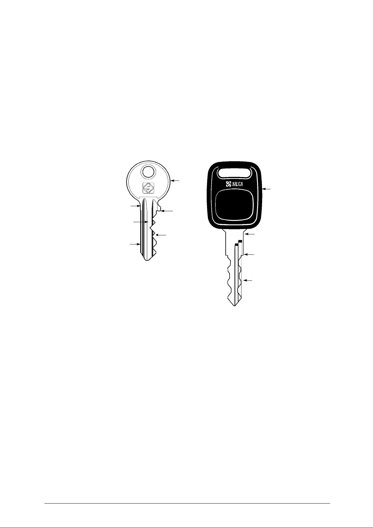
To assist those with little experience of keys and key-cutting, below is an illustration of the terms most
frequently used.
1
1
Fig. 1
1) Head
2) Rim
3) Stop
4) Stem
5) Tip
6) Back
7) Cuts
2
4
6
5
3
7
5
2
3
7
Copyright Silca 2002 1
Page 6
UNOCODE 299 Operating manual - English
GENERAL
UNOCODE 299 has been designed in compliance to the European Community normative (CE).
From the design stage risksforthe operator have been eliminatedinall areas: transport, regulation,cutting
and maintenance.
Further risks have been eliminated by means of protective devices.
The materials used to manufacture this machine and all its components are not hazardous.
U
SE
UNOCODE 299 is designed for cutting keys of ferrous materials: brass, silvernickel, etc.
It must be installed and used according to the instructions indicated by the manufacturer.
If the key-cutting machine is used differentlyor for purposes different from those describedin this manual,
the customer will forego any rights he may have over Silca S.p.A. Furthermore, unforeseen danger to the
operator or any third parties may arise from incorrect use of the machine.
I
NCORRECT USE
Operator negligence resulting in improper use of this machine or failure of the operator to observe the
instructions written in this manual. The manufacturer may decline all guarantees and responsibilities.
It is therefore essential to carefully read this operating manual.
I
MPROPER USE OF ELECTRIC CONTACT
CAUTION:
• it is not permitted to cut ultralite anodized aluminium keys, plastic keys or any keys with materials
that do not have electrical conductivity by means of electric contact.
• cuts cannot be repeated on the same side of the key when electric contact cutting is used.
F
URTHER RISKS
No further risks will arise when properly using the UNOCODE 299.
P
ROTECTION AND SAFETY PRECAUTIONS FOR THE OPERATOR
UNOCODE 299 is entirely built in compliance to the Machine Directives. The operations for which it has
been designed are easily carried out with no risk to the operator.
The adoption of general safety precautions and observation of the instructions provided by the
manufacturer in this manual eliminate all human error, unless deliberate.
UNOCODE 299 is designed with features which make it completely safe.
• Power supply
UNOCODE 299 is supplied with electricity by means of a grounded plug and differential switch.
• Start-up
Themachine is turned on by means of a master switch that is locatedon the Unocode’slower left backside.
• Maintenance
The operations toregulate, service, repair and clean the machine are structured in thesimplest and safest
way possible. Parts that the operator can dismount cannot be incorrectly replaced therefore avoiding any
risks.
• Machine identification
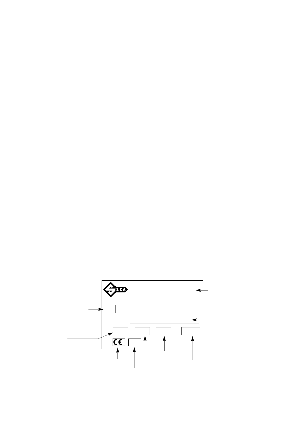
The machine is provided with an identification label which includes the machine’s serial number (fig. 2).
SILCA SpA - Via Podgora 20 (Z.I.)
®
31029 VITTORIO VENETO (TV) ITALY
(0438) 9136
☎
Telefax (0438) 913800
Telex 410579 SILCA I
Fig. 2
type of
machine
working
voltage
CE mark
TIPO
TYPE
N˚ MATRICOLA
SERIAL No.
VOLT
year of
manufacture
Hz. WATT
A.
absorbed
current
working
frequency
2 Copyright Silca 2002
manufacturer’s
address
serial No.
absorbed power
Page 7
Operating manual - English UNOCODE 299
1 MACHINE DESCRIPTION
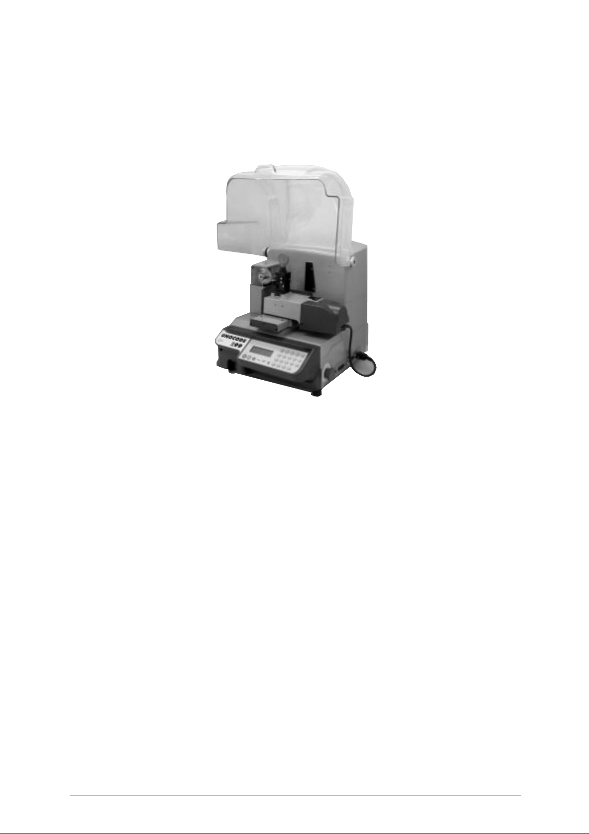
UNOCODE 299 is an electronic machine operating on two axes with controlled movement. Accurately
studied, it adds a high degree of cutting precision to operating speed and ease of use.
UNOCODE can be used in 2 different ways:
• entering the key code directly by means of the machine keyboard
• linking to a PC and Silca software
Fig. 3
1.1 MAIN CHARACTERISTICS
• Movements
Movement of the two axes (X-Y) operates on ball screws activated by step motors, on rectified roller
guides.
• Clamp
Standard four-sided clamp, specially designed to grip most flat keys.
• Working tool
Consists of a cutter in HSS (high speed steel), that is easily replaced.
Suitable to the type of work and speed rotation needed. Optional hard metal carbide cutter.
• Display
Rear-illuminated and placed on the front of the machine.
Display with 4 rows of 20 characters each.
Its technical features and positioning make it highly practical in use.
Copyright Silca 2002 3
Page 8

UNOCODE 299 Operating manual - English
1.2 SAFETY
• Protective shield
The transparent protective shield is designed to cover the working parts as completely as possible,
ensuring operator safety.
The shield (U) (fig. 4, page 5) must be raised in order to fit keys for cutting or carry out other operations.
Raising of the shield is controlledbyamicroswitch and disactivates the operating and movementfunctions,
including the cutter. A special message appears on the display to warn that the shield is not closed.
To re-start the work cycle, place the shield in its original position and press START on the machine’s
keyboard.
• Emergency stops
The red emergency button (N)(fig. 4, page 5) placed on the right-hand side of the machine isused to stop
it immediately in the event of faulty operation or danger for the operator.
When the cause of the emergency has been eliminated, turn the button 45˚ clockwise to disactivate it.
NOTE: the operator is responsiblefor keeping the area around thebutton clear so that it canbereached
• Cutter motor protection
The cutter motor is protected against overheating by a cut-out switch (located inside the motor) that will
automatically stop the motor if it reaches a certain temperature. Should the switch activate:
1) turn the machine off and disconnect the power supply cable.
2) contact Silca’s Technical Assistance Dept.
as quickly as possible.
4 Copyright Silca 2002
Page 9
Operating manual - English UNOCODE 299
1.3 MAIN WORKING PARTS
U
E
I
H
D
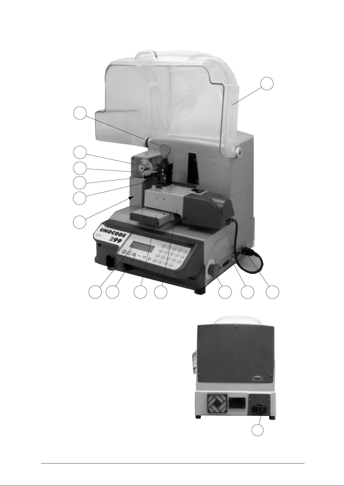
Fig. 4
F
V
A - master switch
B - keyboard
C - display
D - clamp
E - clamp knob
F - key gauge
H - cutter
I - cutter shield
N - emergency button
O - serial port
R - Y axis connector
S - X axis carriage
T - Y axis carriage
U - protective shield
V - swarf tray
BC
S T
N
Q R
A
Copyright Silca 2002 5
Page 10

UNOCODE 299 Operating manual - English
1.4 TECHNICAL DATA
Electricity supply:
230V-50Hz (110V-60Hz) (100V - 50/60Hz)
Maximum absorbed power:
230V: 2 Amp. 250 Watt - 110V: 3,6 Amp. 250 Watt
cutter motor:
single phase and speed
cutter:
HSS (high speed steel) - optional hard metal carbide cutter
Tool speed:
• 50Hz: 1150 rpm (+/- 10%) - 60Hz: 1100 rpm (+/- 10%)
with pulleys inverted:
• 50Hz: 1830 rpm (+/- 10%) - 60Hz: 2700 rpm (+/- 10%)
Movement:
on 2 axes with ball screws activated by step motors, on rectified roller guides.
Clamp:
universal 4 sided clamp to grip flat, car and cruciform keys
Runs:
X axis: 57 mm Y axis: 32 mm
Dimensions:
width: 500 mm depth: 500 mm height: 420 mm (with raised shield 650 mm)
Mass:
34,5 kg
Noise level:
sound pressure Lp(A) = 85 dB(A) (cutting steel keys)
6 Copyright Silca 2002
Page 11
Operating manual - English UNOCODE 299
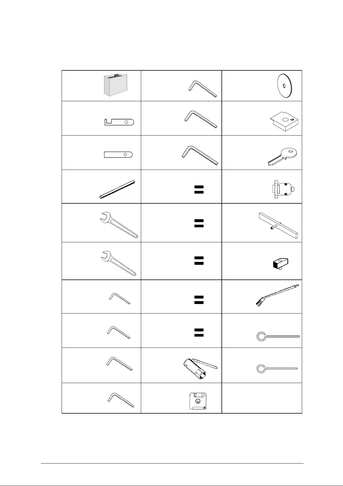
1.5 ACCESSORIES PROVIDED
UNOCODE 299 comes with a set of accessories for its operation and maintenance (tools, hex wrenches,
fuses) supplied in a special tool kit comprising:
tool kit
Tip stop with notch
D402301BA
Tip stop
D402302BA
Cutter release rod
D400754BA
13 mm spanner
D302788ZZ
4 mm allen key
D300224ZZ
5 mm allen key
D300225ZZ
6 mm allen key
D300226ZZ
2 Amp fuse – delayed
D312423ZZ
4 Amp fuse – rapid
D301185ZZ
Z1 template
(regulating disk)
D416657BA
Z2 template
(regulating block)
D416660BA
Z3 template
(regulating key)
D416658LR
Z4 serial test connector
D416661ZZ
Belt tension plate
D416552BA
D202443ZZ
10 mm spanner
D300308ZZ
1,5 mm allen key
D302434ZZ
2 mm allen key
D300221ZZ
2,5 mm allen key
D300222ZZ
3 mm allen key
D300223ZZ
10 Amp fuse - delayed
D316568ZZ
4 Amp fuse - delayed
D308726ZZ
6,3 Amp fuse - delayed
D310652ZZ
19 mm socket wrench
D306963ZZ
WIN-TRANSFER program disk
Anti-tilting device
D508699ZZ
Slanted
brush
D306935ZZ
ø 1,7 mm steel pin
D401225ZZ
ø 1,2 mm steel pin
D401224ZZ
Copyright Silca 2002 7
Page 12

UNOCODE 299 Operating manual - English
2 TRANSPORT
The key-cutting machine is easily transported and is not dangerous to handle.
The packed machine should be carried by at least two people.
2.1 PACKING
The packing for UNOCODE 299 is designed to ensure safe transportation and to protect the machine and
all its parts.
It comprises a pallet base (b) to which the machine is attached, and a cardboard box as a cover (a).
The machine is fixed to the base of the pallet with screwed down brackets that hold it firm into place. This
prevents the machine and its protective shield from any damage.
The closed packing is held in place by two straps which hold the cardboard box firmly on the pallet.
Symbols are printed on the outside of the cardboard box to give instructions and warnings for
transportation.
a
Fig. 5
b
Keep dry
To prevent any damage to the machine it is advisable to save and use the brackets provided for future
transportation.
Handle with care
This side up
Use no hooks
8 Copyright Silca 2002
Page 13
Operating manual - English UNOCODE 299
2.2 UNPACKING
To remove the machine from the packing box:
1) cut the straps with scissors and remove
2) raise the top part of the cardboard box
3) loosen the screws, both on the front and back brackets that hold the machine to the pallet.
4) use the special spanner (provided in the tool kit), to loosen the nuts on the machine’s feet.
5) remove the metal brackets and re-tighten the nuts on the feet.
6) check the contents in the box, that should comprise with the following:
1 UNOCODE 299 key-cutting machine
1 set of documents, including: an operating manual, a spare parts list and a guarantee
1 power supply cable
1 tool kit
NOTE: we strongly recommend you keep the packing intact for future transportation.
2.3 MACHINE HANDLING
When the UNOCODE 299 hasbeen unpacked, place it directlyon its workbench; this operationshould be
carried out by at least two people.
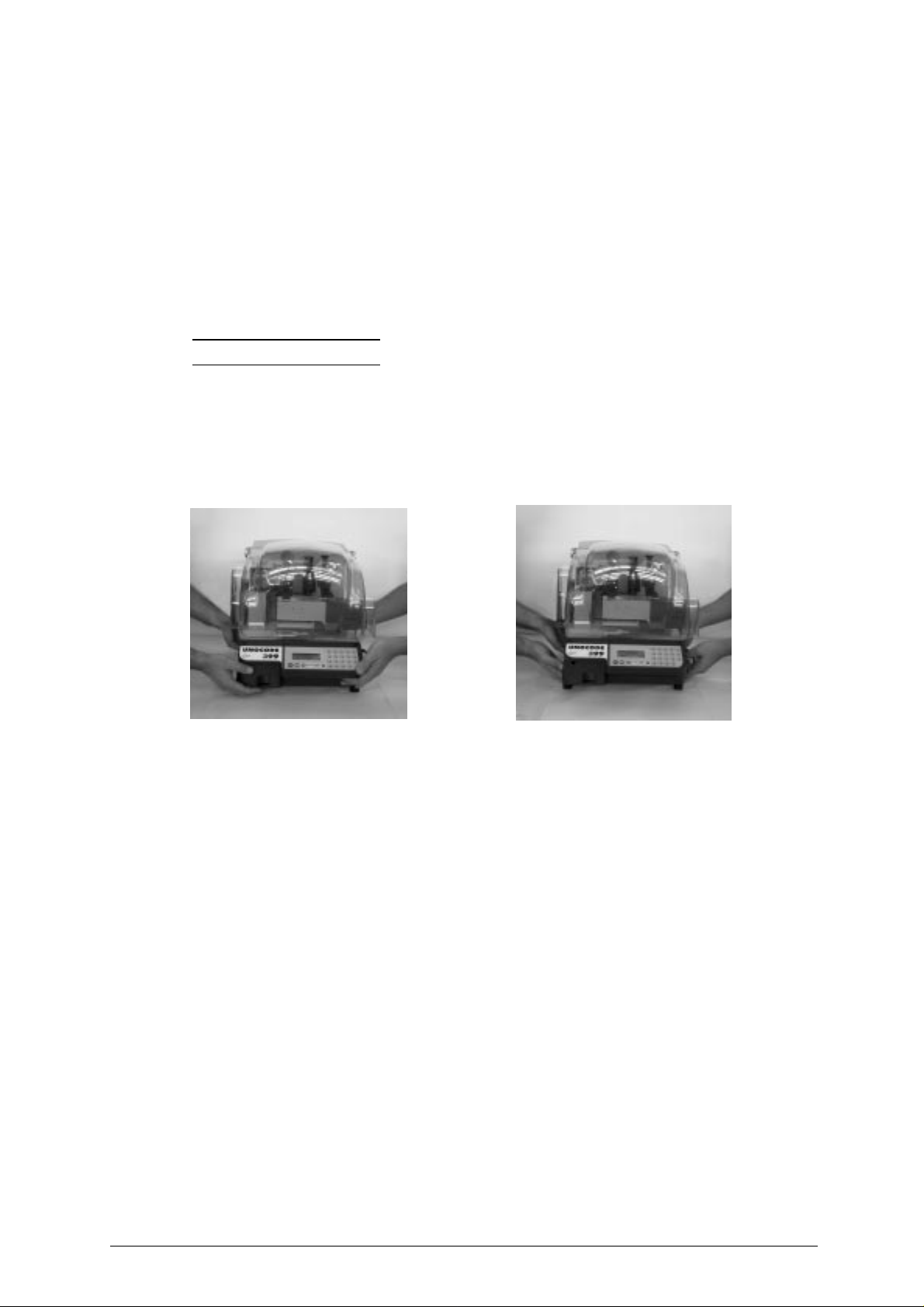
Take care to lift the machine firmly holding the base, and no other part.
ATTENTION: never lift the machine by holding the keyboard stand (fig. 6).
Fig. 6
INCORRECT! CORRECT!
Copyright Silca 2002 9
Page 14

UNOCODE 299 Operating manual - English
3 MACHINE INSTALLATION AND PREPARATION
The key-cutting machine can be installed by the purchaser and does not require any special skills.
It is supplied ready for use and does not need any special set up. However, the operator may have to
control a few things before operating the machine.
3.1 CHECKING FOR DAMAGE
UNOCODE 299 is solid and compact and will not normally damage iftransport, unpacking and installation
have all been carried out according to the instructions in this manual. However, it is always advisable to
check that the machine has not suffered any damage.
3.2 ENVIRONMENTAL CONDITIONS
To ensure that the best use is made of the key-cutting machine, it is important to place it in a well-aired
area which is not too damp.
The ideal conditions for the machine are:
temperature between 10˚C and 40˚C; relative humidity: approx. 60%.
3.3 POSITIONING AND INSTALLATION
1) Place the machine on a horizontal surface, solid enough to support the weight of 34,5 Kg.
- toworkwithease,wesuggestthat the workbench be approximately the height of the operator’s
hip.
- it is important toleave clearance ofat least 30cm behind themachine and on each side to ensure proper ventilation.
2) Ensure that the machines voltage is the same as that of the mains power supply, which must be
properly earthed and provided with a differential switch.
- connect the power supply cable to the power supply socket.
Fig. 7
30 cm
30 cm
30 cm
100 cm
10 Copyright Silca 2002
Page 15

Operating manual - English UNOCODE 299
3.4 DESCRIPTION OF WORK STATION
The machine needs only one operator, who has the following controls at his/her disposal (fig. 4, page 5):
• master switch placed on the back of the machine
• key-positioning clamp
• keyboard
• display
• emergency button
3.5 GRAPHICS
• The plexiglas protective shield carries an adhesive warning label (fig. 8). This label must never be
removed.
Do not use compressed air
Fig. 8
for cleaning
Copyright Silca 2002 11
Page 16
UNOCODE 299 Operating manual - English
4 “SET UP” AND USE OF THE MACHINE
4.1 KEYBOARD AND FUNCTIONS
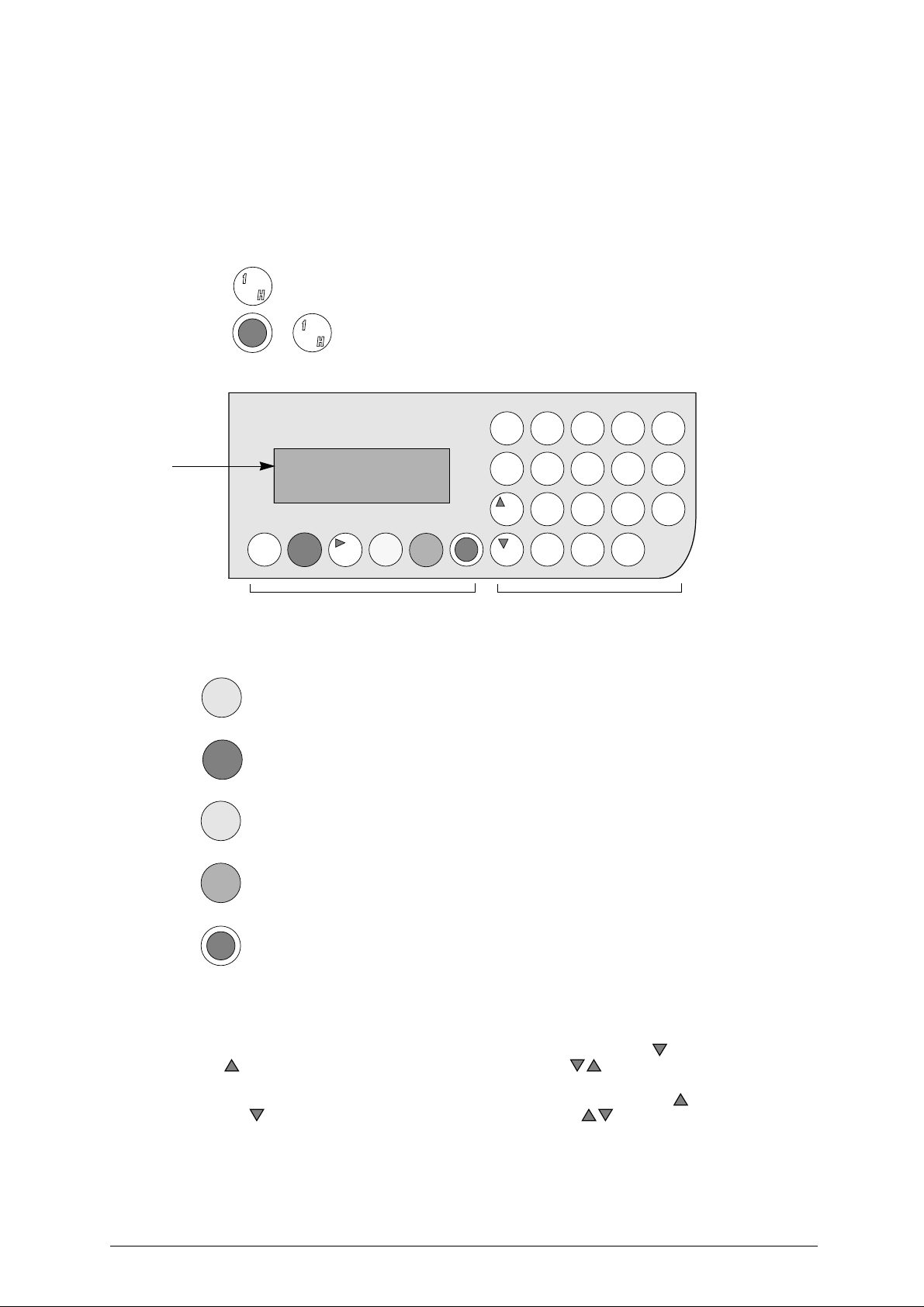
The machine’s keyboard has 19 alphanumeric and 6 function keys.
The alphanumeric keys are used for entering the data card number and the cutting data (numbers and/or
letters) according to the code on the card in use.
Each of the 19 alphanumeric keys contains two characters: the main character (white) which is directly
active, and an alternate character (red), whichcan beactivatedbysimultaneouslypressing the SHIFT key.
E.g.: pressed directly produces: 1
Fig. 9
display
F
UNCTION KEYS
STOP
START
SHIFT
+
Pressed simultaneously produce: H
12345
HI JKL
67890
MNOPQ
ABCD
RSTUV
F
STOP
START
?
ENTER
CLEAR
COPY
SHIFT
E
WXYZ
G
function keys alphanumeric keys
Stop button, particularly when the machine is in motion.
Stops the function in progress at any time in the operation.
Starts the machines operations (only with the shield in its closed position).
ENTER
CLEAR
COPY
Activation of various functions in the menu.
CLEAR: deletes numerical characters.
Pressed in combination with all the keys of the same colour to enter the number or letter
SHIFT
available.
• regulating the display
it is possible to modify the angle of vision on the machine’s display by following the instructions described
below:
• to incline the angle of the display towards the bottom you must press the key and then press the
key, simultaneously keeping them both pressed up until you reach the desired
visualization.
• to incline the visualization of the display towards the top you must press the key and then press
the key, simultaneously keeping them both pressed up until you reach the desired
visualization.
12 Copyright Silca 2002
Page 17
Operating manual - English UNOCODE 299
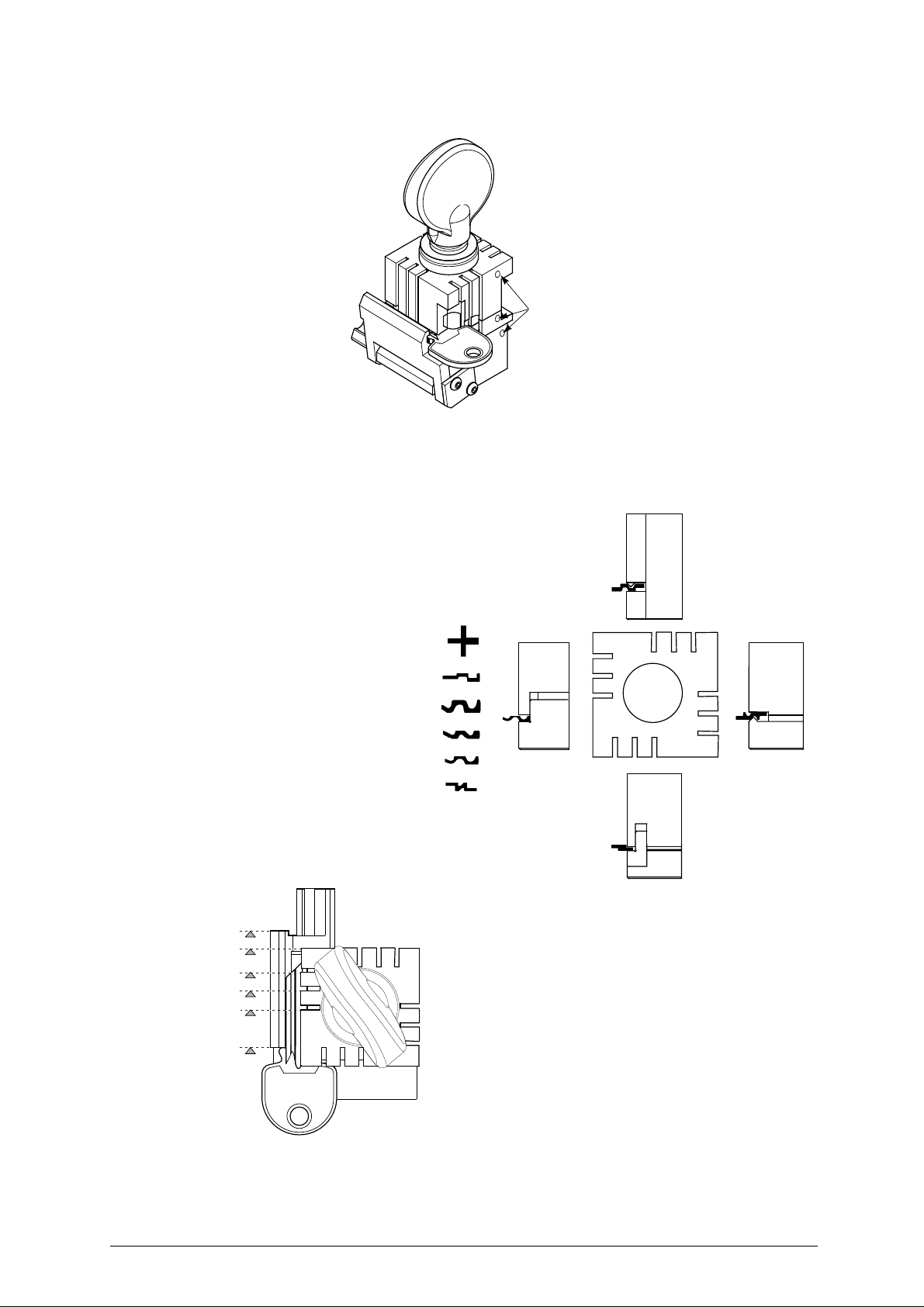
4.2 USE OF THE CLAMP
white
V100 Clamp
Fig. 10
The four-sided clamp ensures excellent grip on the keys placed on their back or profile sides (fig. 11).
• Keys with 1 or 2 cuts to reproduceby code shouldbe fitted mainly on the A and/or Bside of the clamp.
- For keys to be cut by code the
side of the clamp on which to
place the key is shown on the
machines display.
- To fit keys with tip stops, place
D side
the tip stop barprovidedinto the
special grooves (fig. 12).
1
2
3
4
C
1
2
3
B
4
C side
1
Fig. 11
A side
D
4
3
2
1
A
2
3
4
B side
6
1
2
3
4
3
2
1
0
4
4
3
3
2
2
1
1
A
2
4
3
4
C
1
2
3
4
1
Fig. 12 - key stops
Copyright Silca 2002 13
Page 18

UNOCODE 299 Operating manual - English
ATTENTION: when closing the clamp, do not apply excessive pressure
to the knob. Turning the knob approximately 70˚ (equal to
a force of 3NxM) is sufficient to secure the key (fig. 13).
Fig. 13
NOTE: before starting the cutting process the V100 clamps key gauge will automatically tilt itself to its
rest position.
U
SING THE PINS
Copying with the optical reader
Forkeys with narrow stems the pins must be placed between
the bottom of the clamp and the back of the key so that the
key protrudes sufficiently out of the clamp and therefore can
be properly read and cut.
Ifthe key has a narrow stem and is also very thin, 2 pins must
be used (see fig. 14).
2
3
4
3
2
1
A
3
2
4
4
C
1
2
3
4
Fig. 14
14 Copyright Silca 2002
Page 19
Operating manual - English UNOCODE 299
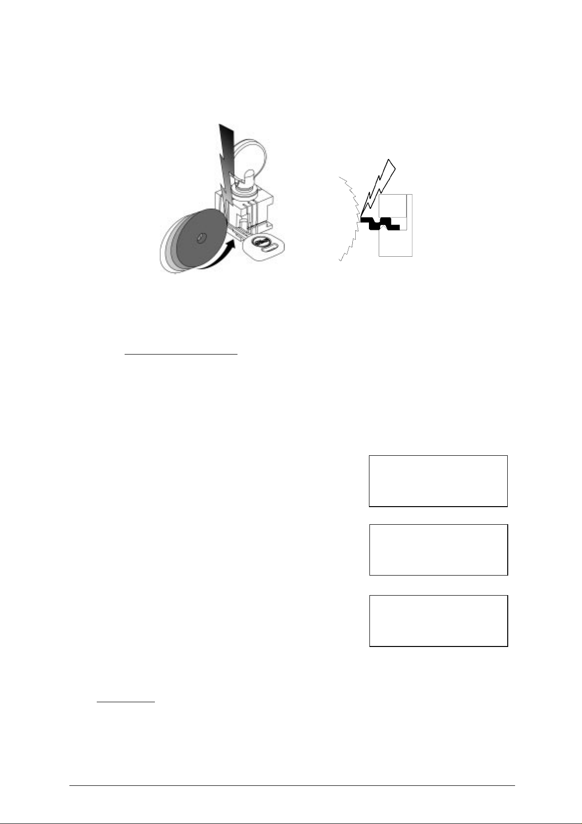
4.3 CUTTING BY ELECTRIC CONTACT
The UNOCODE 299 key-cutting machine is equipped with a low voltage electrical contact device which
permits the cutter to individualize the key blank as it approaches the cutter during the cutting phase (fig.
15).
Fig. 15
This technical solution permits the operator to secure the key to the more appropriate side of the 4 faced
clamp (A, B, C or D) therefore improving the grip on the key, eliminating theneed of pins and/or adaptors.
With the electrical contact card enabled, depth calibration is automatically calculated when the cutter
touches the keys profile during the cutting process.
Electrical contact is guaranteed for keys in steel, brass, silver nickel, Zamakor iron (with or withoutnickelplating).
Improper use of electric contact
• it is not permitted to cut ultralite anodized aluminium keys, plastic keys or any keys with materials
that do not have electrical conductivity by means of electric contact.
Attention: for these types of materials, insert standard cutting.
• cuts cannot be repeated on the same side of the key when electric contact cutting is used.
All data cards provided by Silca are in the machine’s memory. The cards are enabled or disabled for code
cutting by electric contact at Silca’s discretion.
The data cards are divided into 3 types which are distinguished by special symbols shown on the display
(asterisk “*” and “+” ).
1) Clamp: 100/A START
• data card with standard cutting (press START)
Side - 1
Clamp: 100/A Pos.: 0
Cutter: U01 Adapt.: 0
Pieces = 3 [START]
2) Clamp: 100/B START+
• data card with standard cutting (press START)
• alternative: electric contact cutting press SHIFT+START
Side - 1
Clamp: 100/B Pos.: 0
Cutter: U01 Adapt.: 0
Pieces = 3 [START] +
3) Clamp: 100/* START+
• data card with electric contact cutting (press START)
• alternative: standard cutting press SHIFT+START
Side - 1
Clamp : 100/* Pos.: 0
Cutter: U01 Adapt.: 0
Pieces = 3 [START] +
A - B: indicate the side of the clamp
+ : indicates the alternative activated with the SHIFT+START keys
* : indicates that the key can be clamped to any side of the clamp when the data card is enabled for electric contact.
Operating keys:
SHIFT+START: changes the cutting procedure (‘standard’ or ‘by electric contact’) and starts cutting.
START: begins the cutting process.
ATTENTION: the alternative selected with the SHIFT+STARTkeys (‘standard’ or ‘by electric contact’) ismaintained
as long as the chosen data card is in use. When the procedure has been selected, simply press
START for successive cutting operations.
Copyright Silca 2002 15
Page 20
UNOCODE 299 Operating manual - English
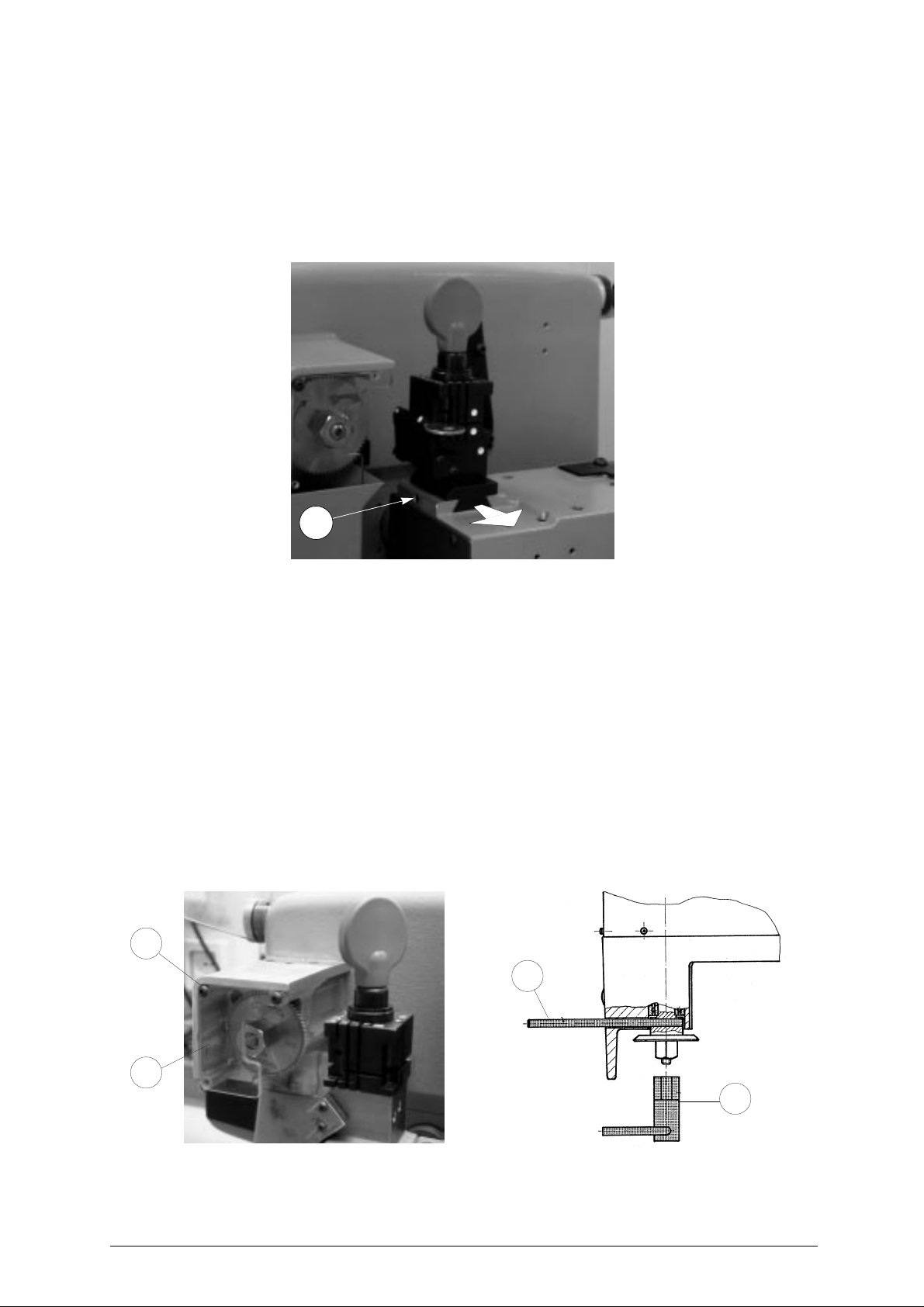
4.4 FITTING THE CLAMP TO THE MACHINE
To remove the clamp unit:
- loosen the grub screw (D2) (fig. 16) and slide the clamp out of the dovetail guide.
To install the clamp unit on the machine:
- slide the clamp into the dovetail guide, pushing it all the way in, then secure it by tightening the grub
screw (D2).
These instructions refer exclusively to the standard clamp (V100). For the use of optional clamps please
refer to the instructions provided along with them.
D2
Fig. 16
4.5 CUTTER
The majority of keys utilize the standard cutter (U01) for code cutting. Only in certain cases some special
keys with particular type cuts require different cutters.
To change the cutter see chapter 4.6.
4.6 CHANGING THE CUTTER
1) raise the protective shield.
2) remove the cutter protective shield (i) by loosening the screw (i2).
3) slide thecutter release rod (X)into the hole locatedonthe left side ofthe machines cutter shaftchassis
(fig. 17).
4) loosen the cutter locking nut (turning it clockwise) with the19 mm socket wrench (X1) provided with the
machine.
ATTENTION: the thread is left-handed.
5) replace the cutter, then tighten the nut (turning it counter-clockwise) and remove the rod from its hole.
6) place the cutters protective shield (i) back into position securing it with the screw (i2).
i2
X
i
X1
Fig. 17
WARNING: when replacing a worn cutter with a new one or with a re-sharpened cutter consult Ch.5.5 "[4]
16 Copyright Silca 2002
Calibrations", page 26.
Page 21
Operating manual - English UNOCODE 299
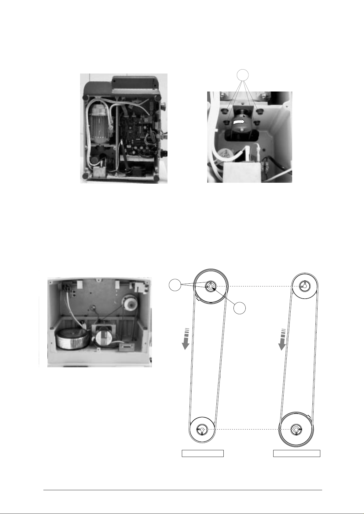
4.7 INVERTING THE PULLEYS
This operation must be carried out when the operator intends to use a hard metal carbide cutter
(optional), in order to adapt the cutter speed to the new characteristics of the cutter’s material.
W
Fig. 18
1) turn the machine off and disconnect the power supply cable.
2) remove the back and bottom metal panel (ch.7.8 and ch.7.9, page 50).
3) loosen the 4 motor locking screws (W) (fig. 18) and remove the belt.
4) loosen the 2 grub screws securing the pulley and remove it from the motor shaft.
5) fit the cutter shaft locking rod and use the allen key provided toloosen the screw(A1) and grubscrews
(A2) on the pulley (fig. 19).
6) invert thepulleysand secure them by tighteningthegrub screws, fit the screwandwasher on the cutter
shaft.
7) remount the belt and adjust its tension (ch. 7.4, page 46).
8) remount the back and bottom metal panel.
9)
enter the ‘cutter material’ function in
Ch.5.7 "Options [6]", page 36,
and alter the speed
.
Fig. 19
A2
for HSS cutter
cutter shaft
A1
motor shaft
for carbide cutter
Copyright Silca 2002 17
Page 22
UNOCODE 299 Operating manual - English
5 OPERATING GUIDE
Introduction
The Operating Guide below explains how to use the UNOCODE 299 without a Personal Computer
All operations to manually use the key-cutting machine are explained step by step
The programs available for Personal Computers connected to the key-cutting machine are able to
transmit data for cutting
ProgramsforPersonalComputer eliminatemanual proceduresof certainfunctions,once the data has
been transmitted to the machine it bypasses some of the operating guides screens
When the UNOCODE 299 is used with a Personal Computer, the operating guide does not change
its displays logic, with the exception of all the screens that are rendered unnecessary
.
5.1 INITIAL OPERATIONS
.
.
.
.
When the key-cutting machine has beenplaced on its workbench and connected to themains
page 10),
1)
2)
3)
When the machine is turned on, for a few
seconds the display shows the internal
software version and the machine model
proceed as follows
make sure that the emergency button is not turned on
turn the machine on by means of the main switch that is located on the back of the machine
to check or alter the parameters for use of the machine, consult the
page 36).
:
.
"Options [6]"
:
UNOCODE 299
version 1.0.023
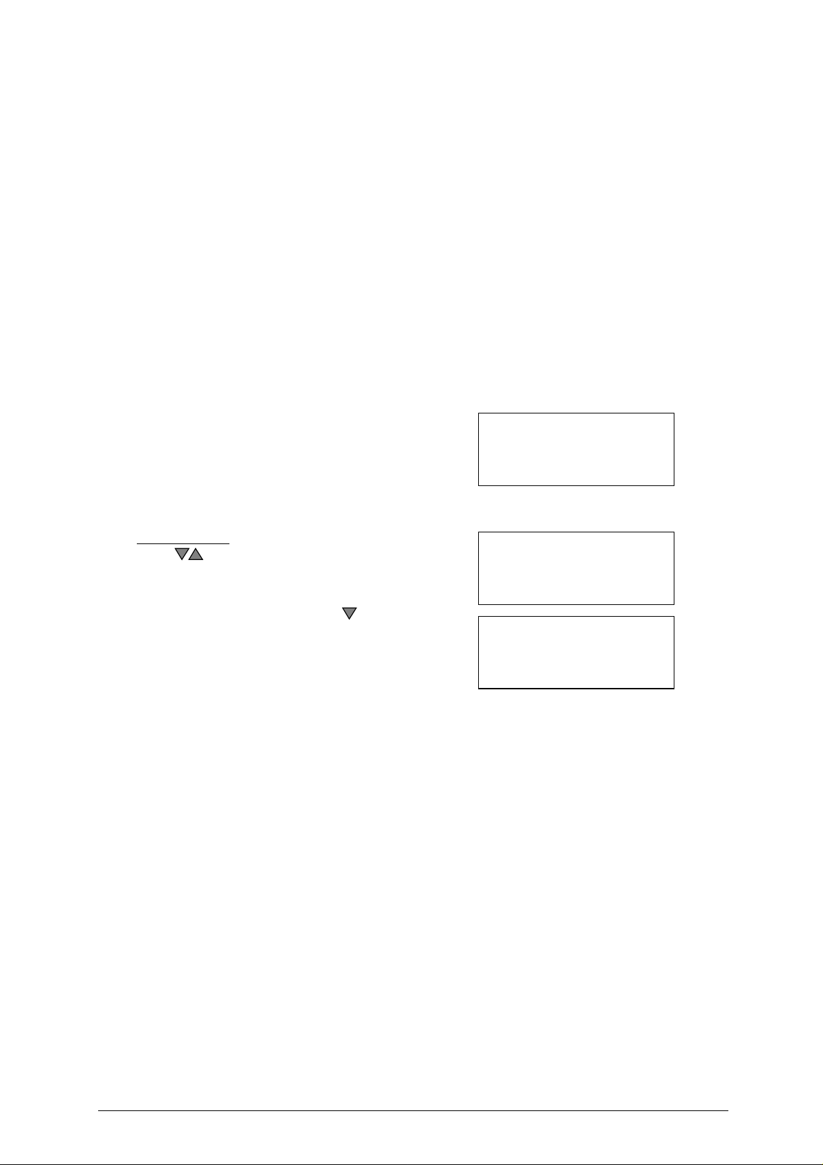
M
AINMENU
Operational keys:
use the keys to move the cursor to the option required
and press ENTER or directly press the numbered key
corresponding to the option number.
The>>symbol indicates that themenu contains other items
which can be reached with the arrow key
.
1 - Copy by code
2 - List of codes
3 - Queue from PC
4 - Calibrations >>
5 - Maintenance
6 - Options
menu
(ch.3.3,
.
(ch.5.7,
18 Copyright Silca 2002
Page 23
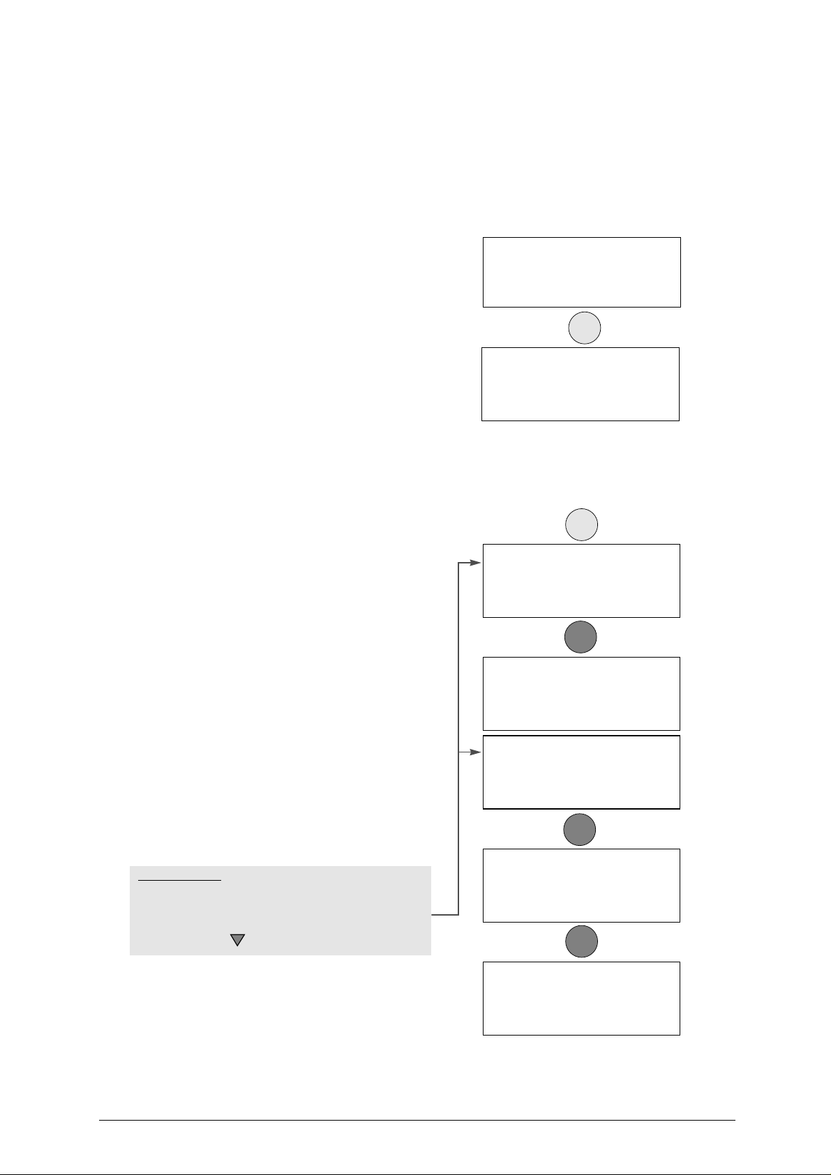
Operating manual - English UNOCODE 299
5.2 [1] COPY BY CODE
One part of the machine’s memory is used for the data cards.
A data card is a database of cutting‘spaces’, ‘depths’andanglesforallthe keys in the machines data base.
The number of data cards is increased periodically when the ‘Silca Code Program’ is updated. The
updates can be bought separately and easily installed to a P.C. then transmitted over to the
machine.
As the memory can be rewritten, the Personal Computer updates the data cards automatically.
STANDARD data card (S.):
comprises the ‘spacesand depths’ database as described in the introduction to
GUIDE", page 18).
The source of this information can be the SILCA Car
Book, ‘Silca Code Program’, catalogues and other
documents available from Silca
USER data card
personalizeddatacardscanbecreated by means of
a function available in the ‘Silca Code Program’.
Cards can be stored from the P.C. to the machine’s
memory and the operator may recall them at any
time
.
1) enter the data card No. (e.g.: STANDARD =
50).
2) enter the cutting data.
(ver. DB : 1)
gives the number of the Silca board database version installed on the machine.
. . . . . . . :
the dots on the display represent the maximum
number of cuts that are permitted. The same data
card can be used for anumberofkeys with different
numbers of cuts. If a key is used with fewer cuts
than the dots shown on the display, simply enter a
partial combination.
3) Press ENTER.
Clamp
: V100/*
The special symbol (asterisk) means that the cuts
will be made by electric contact (ch.4.3, page 15)
therefore it isunnecessary to select theclamp side.
Pos.: 0
Place the key to be cut into the V100 clamp using
the stop that is shown.
Cutter: U01
Recommended cutter
Pieces:
enter the quantity of keys to be cut (max.255).
4) proceed withcuttingthe first side by pressing
the START key.
5) turn the key over and cut the second side.
Operating keys:
SHIFT+START: changes the cutting procedure (‘standard’ or
‘by electric contact’) and starts cutting.
START: begins the cutting operation.
SHIFT+ arrow key selects the side of the key to be cut.
(U.):
.
Ch.5 "OPERATING
.
Enter card number:
STANDARD = 50
USER = 0
(ver. DB : 1)
ENTER
Side 1 x 2 S. 50
. . . . . . .
Possible depths:
1234
2213442
ENTER
Side: 1
Clamp.: 100/* Pos. : 0
Cutter: U01
Pcs = 1/2 [START]+
START
CUTTING IN PROGRESS
Copy: 1 of: 2
Side 1
Side: 2
Clamp: 100/* Pos. : 0
Cutter: U01
[START]+
START
CUTTING IN PROGRESS
Copy: 1 of: 2
Side 2
START
-
when the last side of the last key has
been cut, the screen shows
:
Copyright Silca 2002 19
Copy: 2 of: 2
finished.
More copies?
No = STOP Yes = ENTER
Page 24
UNOCODE 299 Operating manual - English
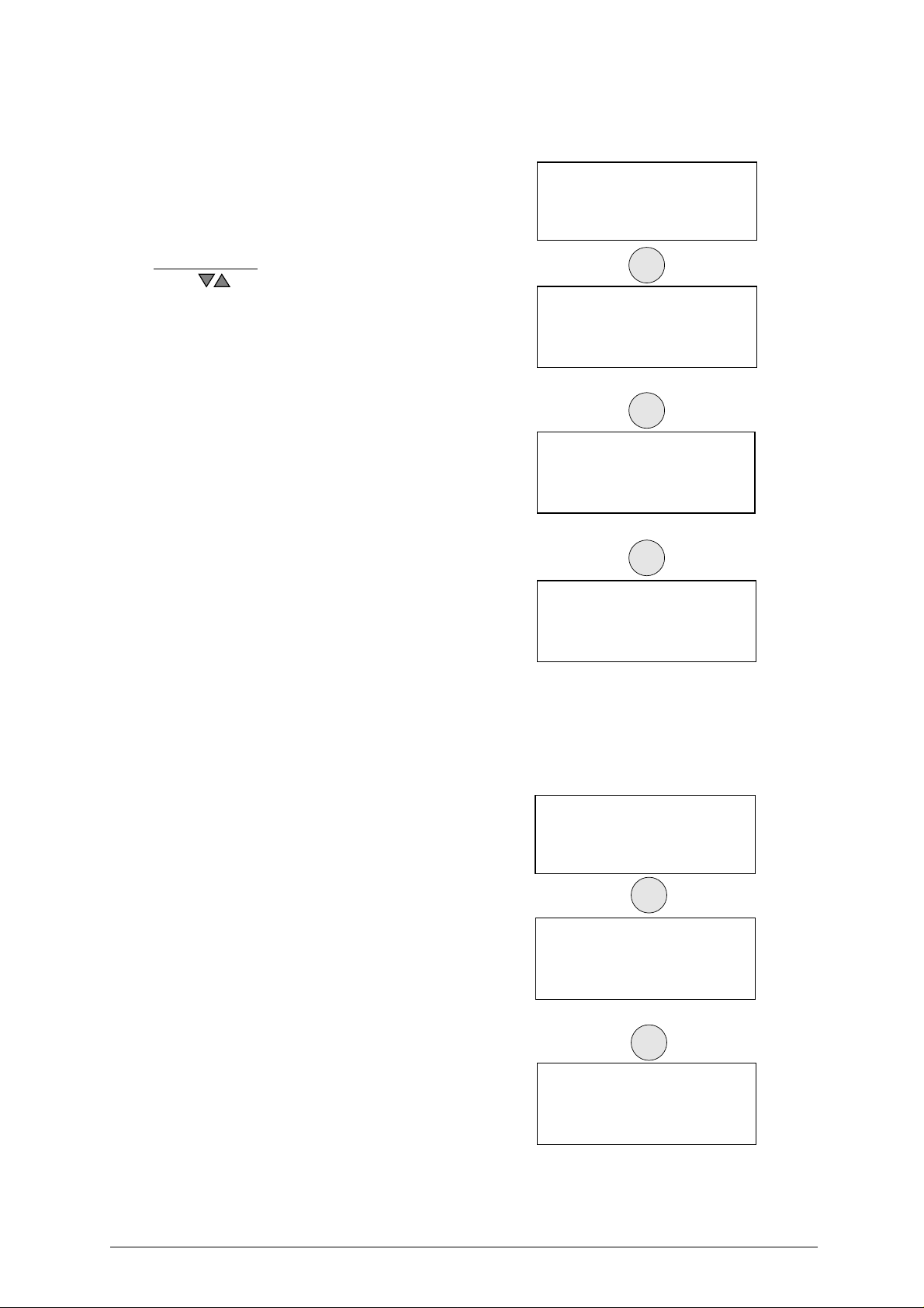
5.2.1 SPECIAL CASES
• Cutting a key with two asymmetrical sides
Enter card number
STANDARD = 115
USER = 0
(ver. DB : 1)
Operational keys:
use the arrow keys to be able to visualize bothsides of
the keys possible cuts on the machines display.
Proceed with the cutting process
.
ENTER
Side 1 S. 115
. . . . .
Possible depths:
4321
1112213331
ENTER
Side 2 S. 115
. . . . .
Possible depths:
4321
1121123313
ENTER
Side: 1
Clamp : 100/A Pos. : 0
Cutter: U01
Pcs = 1/1 [START]
• Inadmissible cutting
When the machine is used manually with certain data cards, it may not be possible to carry out certain
entered combinations. This happens when the cutting depths are not compatible in the order the user
entered the possible cuts.
Example:
Enter card number
STANDARD = 174
USER = 0
(ver. DB : 1)
ENTER
Side 1 S. 0174
. . . . .
Possible depths:
012345678
08213
ENTER
non-feasible
combination!
20 Copyright Silca 2002
Page 25

Operating manual - English UNOCODE 299
The reason for the conflict between certain
cuts is explained simply in the case shown
With regard to the cut that originated the
message <inadmissible combination> it can be
seen that between the two deep cuts (8) and the
constant angle (100˚) the intermediate cut (0)
would be removed.
This happens whenthe cutting angleN (Normal)
is not made variable by means of the type of cut
L (Laser) (page 22).
The new drawing of the key shows how for the
same cutting process (80846) the cutting angles
are automatically calculated by the conjunction
of the cutting base with a straight line.
This aspect, admissible with certain car keys, is
more commonly knownas ‘the idealcutting line’.
ATTENTION: in this example it can be seen that the ß
angle is less than 45˚. This could cause
serious problems with a lock, making it
difficult or impossible to place the key into
the cylinder or remove it.
Control of the combinations in the Options menu can in any case be disabled (chap. 5.7).
.
Fig. 20
?
8
04
α
8
04
β
α
β
α
8
8
6
α
α
6
γ
α
δ
Fig. 21
Copyright Silca 2002 21
Page 26
UNOCODE 299 Operating manual - English
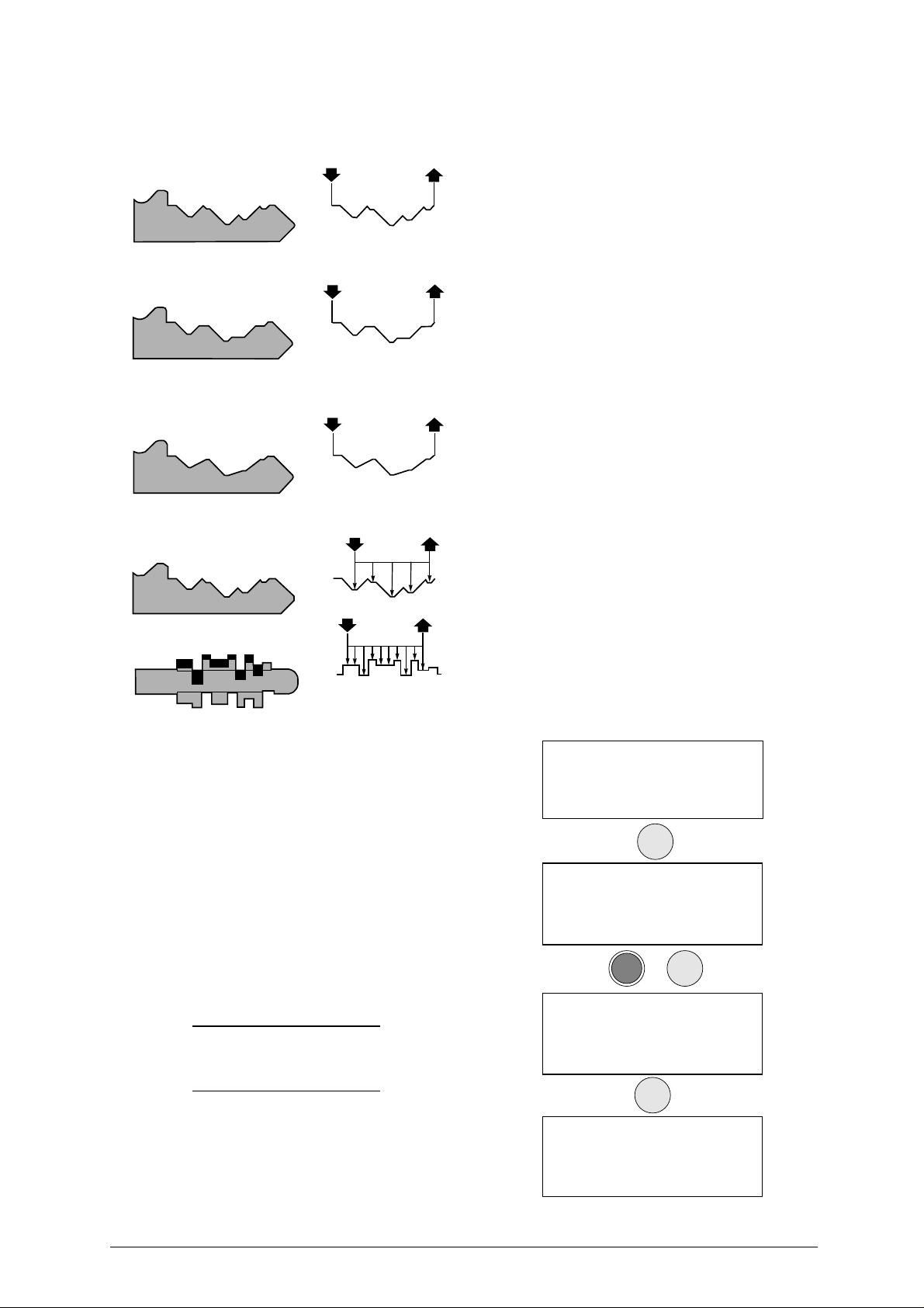
• Types of cut
All the data cards provided by Silca have the type of cut pre-set according to the original parameters.
The types of cut possible with UNOCODE 299 are: Normal, Flat, Laser and Vertical
.
N
NORMAL
For conventional car and door keys
P
L
FLAT
Mainly used for car keys where the cut edges are
rounded to facilitate the movement of the blades when
the key is put into the lock
ASER
L
Conjunction of the cutting angles is determined
automatically by the machine, allowing cuts to be made
with variable angles; this facilitates the smooth entry of
the key into the lock, prolonging the working life of the
key
.
.
.
V
V
ERTICAL
V
Necessary for special keyswithsmall bits (Silca art.FO19P,
FO21P...) where a special cutter is required.
When this cutting method is used a special angledcutter
is needed
.
EXAMPLE OF HOW TO CHANGE THE TYPE OF CUT
All the technical data regarding the types of
cuts stored in the machine’s memory can be
changed according to the user’s requirements
enter data card number (e.g.
1)
before entering the cuts press the
2)
combination of keys
3)
enter the “L” type cut by pressing the
SHIFT+L
NOTE:
4)
enter the combination andproceed with the
operations described in
keys
-
the letter in brackets (L) indicates the
type of cut recommended by Silca
for certain cuttingmethods the standard
cutter U01 must be replaced with a
specific cutter
cutter", page 16).
SHIFT+ENTER.
to set the laser type cut.
(Ch.4.6 "Changing the
: nr.50)
.
ch.5.2, page 19.
:
Enter card number
STANDARD = 50
.
USER = 0
(ver. DB : 1)
ENTER
Side 1 x 2 S. 50
. . . . . . .
Possible depths:
1234
+
SHIFT
ENTER
S. 50
Cutter: U01
Cut type (L) = L
Alternative : N P
ENTER
Side1x2 S.50
112233
Possible depths:
1234
22 Copyright Silca 2002
Page 27

Operating manual - English UNOCODE 299
• Changing the cutter
Some of the data cards stored in the machine’s memory require a different cutter from the standard U01
cutter.
EXAMPLE WITH FO21P key
:
Enter card number
STANDARD = 0
USER = 0
(ver. DB : 1)
220
ENTER
Side 1 x 4 S. 220
. . . . . .
Possible depths:
1234
ENTER
Replace the cutter according to the instructions
in Ch.4.6 "Changing the cutter", page 16.
• Adapters
Some of the data cards provided by Silca may
show a new parameter (Adapt.: 7) which indicates
the type of accessory that is needed to cut the key
in question.
See the ‘Unocode Adapters’ leaflet included with
the Unocode 299 machine.
ATTENTION !!
Install cutter:
05
ENTER
Is cutter:
05
installed?
No = STOP Yes = ENTER
Side 1
Clamp: 100/A Pos.: 0
Cutter: U01 Adapt.: 7
Pcs = 1/1 [START]
Copyright Silca 2002 23
Page 28

UNOCODE 299 Operating manual - English
5.2.2 LIMITED ACCESS TO DATA (PROTECTED SYSTEMS)
Silca has predisposed limited accessto some of the datain the Database, in compliancewith agreements
with some makers. Limitations apply to:
- DATA CARD: If the key-cutting card is protected, access is denied.
Gain access to protected data in the following way:
- request the maker’s authorization.
- communicate to Silca :
- The key-cutting machine SERIAL NUMBER
- The ACTIVATION CODE
- Key-cutting Machine ID
Silca will issue a Password to enter in order to enable key-cutting of the protected system.
Example: Silca provides a protected data card No. 11.
When card 11 is selected from menu -1- the following
appears on the screen:
PROTECTED CARD
Mach.ID: 12345
Code: SKPSC00011
Password: 0
When authorization has been received from the maker, apply to Silca for a password, providing the
following information:
- Key-cutting machine serial No. 1170145634567
Read the serial number on the ID plate fixed to the back of the machine.
- Machine ID 12345
visible in the password application box or by selecting menus 6-12-1 on the machine.
- ACTIVATION Code SKPSC00011
shown ONLY when access to protected data is attempted.
Once obtained, enter the password on the Password
line, as shown in the example given above.
If the correct password has been entered, the screen
shows:
The password can be saved so that it need not be entered whenever the protected data card is used, or
not saved so that access is limited only to the person in possession of the password.
5.3 [2] LIST OF CODES
ATTENTION: function currently not available! (for future use)
CORRECT PASSWORD
Save the password ?
No=STOP
Yes
=ENTER
24 Copyright Silca 2002
Page 29
Operating manual - English UNOCODE 299
5.4 USE OF THE MACHINE WITH A PERSONAL COMPUTER
In the previous pages theUNOCODE 299 key-cutting machine hasbeen analysed in allits parts from
the point of view of manual use, i.e. operating from the keyboard incorporated in the machine to cut
keys by code
It is now necessary to examine the very important facility with which it is possible to connect up to a PC in
order to receive data directly from the computer.
Taken for granted that the user is in possession of some Silca software, the following are the
possibilities available
The ‘Silca Code Program’ makes it possible tocarry out searches by codefor cutting data and to store the
information in a special work queue (or file).
This is a specialfunction which has beencreated to help thoseusers who wish towork with a number
of simultaneous searches. After having carried out a codesearch,the information is simply filedin the
special work queue then everything is transferred to the UNOCODE 299
The information transmitted by the Personal Computer cannot be altered manually. Each line transmitted
corresponds to a stage in the cutting process for one or more keys.
As described above, for each cutting process transmitted the number of pieces to be cut is set¸ a ‘+’ sign
shows when the cycle is finished.
The ‘+’ sign warns the operator that the last cutting operation has been carried out.
Should a work queue be interrupted, turn off the UNOCODE 299. When the machine is turned on again
and the <PC queue> is called up, the list reappears, starting from the first line.
5.4.1 [3] QUEUE FROM PC
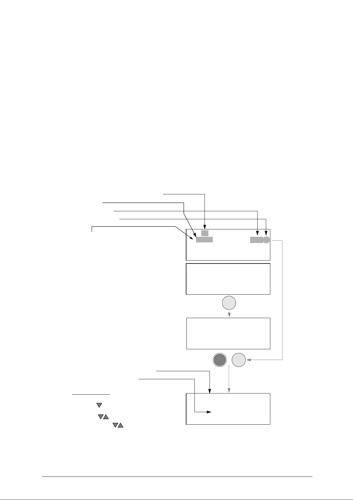
The data received from the PC are presented in one form only:
• quantity of keys in queue transmitted
• key code
• card number
• quantity of keys
.
.
.
• the “+” markindicates that all three keys (or
more) have been cut.
• the “-” mark indicates that the total quantity
of keys referring to its code have not been
cut.
Pressing the ENTER key takes us to the
‘Copying by code’ procedure. From this point
on the operational functions are the same as
those described in ch.5.2, page 19.
C.=
data card from PC
.
When the SHIFT + ENTER keys are pressed
additional data referring to the choosen code
can be visualized, such as:
• Customer’s name
• Key blank
Operational keys:
To quickly go to the next key to be cut, strike the
arrow key
where she or he stopped the previous operation
arrow keys
SHIFT + arrow keys :
SHIFT+ENTER
key item linked to the selected code
When the START key is pressed the cursor will
automatically position itself on the first key code that
indicates the “-” mark.
. Doing so the operator starts
:
to scroll the lines.
to scroll 4 linesatatime
keys to show customer data and
.
from
.
6 CODES RECEIVED
1+ AB100 [234] 3
2 - AB101 [234] 3
3 - AB102 [234] 3
4 - 2315 [122] 5
5 - 1251 [122] 5
6 - W109 [567] 5
. . . .
ENTER
Side 1 C.234
1234
Possible depths:
1234
+
SHIFT
ENTER
GIUSEPPE VERDI
ART. GT10P
.
Copyright Silca 2002 25
Page 30
UNOCODE 299 Operating manual - English
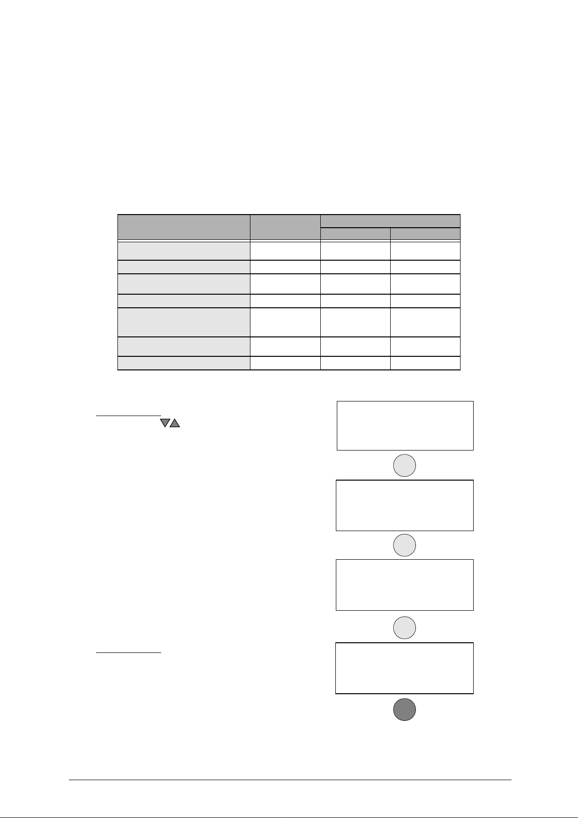
5.5 [4] CALIBRATIONS
The following components on the machine havea specific‘self-setting’procedurewiththeuse of regulating
templates (Ch.1.5 "Accessories provided", page 7).
- CLAMPS
- CUTTERS
ADAPTERS provided as optionals do not require calibrating. However, if necessary adjustments can be
made to the cutting data, according to the procedures described in Ch.5.5.3 "Manual adjustments", page
30.
In the circumstances listed below (see events) it may be necessary to re-set one or all of the clamps and/
or cutters thatthe user has in possession. This operation is semi-automatic and requiresclose attention to
the instructions listed below.
EVENT MACHINEZEROES CALIBRATION (chap. 5.5, pag.26)
CLAMPS CUTTERS
Electronic board replacement YES
Replacement of sensors YES NO NO
V100 clamp replacement
(with a new one of the same type)
Replacement of the cutter shaft SI NO NO
Re-sharpening of existing cutter
and/or cutter replacement
(with a new one of the same type)
Installation of optional clamps NO YES
Replacement of the ball screws YES NO NO
(see ch.7.6, page 48)
NO YES NO
YES NO YES
YES
(see ch.7.6, page 48)
(if applicable)
YES
(see ch.7.6, page 48)
NO
1)
Enter the ‘Calibrations’menu #4
Operational keys:
use the arrow keys to move the cursor to the option required and press ENTER or directly press the numbered key
corresponding to the option number.
.
2) Select ‘Clamps’ #1.
5.5.1 CALIBRATING THE V100 CLAMP
Before starting the clamp calibration, make
sure that there are no keys and/or adapters
fitted in the V100 clamp.
Operational keys:
SHIFT+ENTER: to select and visualize each side of the clamp
(where applicable).
STOP: to exit the menu.
1 - Copy by code
2 - List of codes
3 - Queue from PC
4 - Calibrations >>
ENTER
1 - Clamps
2 - Cutters
3 - Adaptors
ENTER
Clamps
V100
V101
V102
ENTER
V100 SIDE A
Adjustment: SIDE A
X = +00 Y = +00
To calibrate [START]
26 Copyright Silca 2002
START
Page 31
Operating manual - English UNOCODE 299
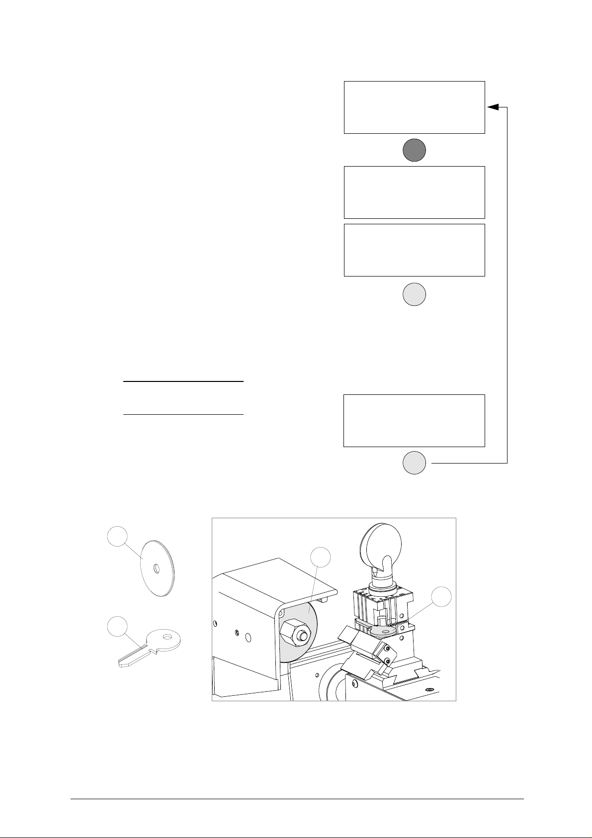
3) replace the cutter with the (Z1) template (fig.
22). To remove the cutter follow the
instructions on page 16, ch. 4.6 "Changing
the cutter".
4) insert the (Z3) template to the side of the
V100 clamp that is shown on the machine’s
display.
5) close the protective shield.
6) press START.
V100 SIDE A
Install Z1 & Z3 temp.
See operating manual
[START]
START
V100 SIDE A
- this will automatically startthe setting of
the V100 clamp by means of electric
contact between the two templates.
Detection
in progress!
V100 SIDE A
X = +002 Y = +004
- the display shows the differences from
the theoretical values.
No = STOP Yes = ENTER
Save data?
7) to save the data press ENTER.
ATTENTION: if the STOP key is pressed, thenew settings
will be lost. If so, only the previous setting
values will remain valid.
NOTE: the settings will be accepted only if the
Z1
tolerances remain within a range
between –30/+30 hundredths of a mm.
- if the tolerances exceed the accepted
range the machine’s display will show
an error message:
-
carefully follow the instructions and
repeat the procedure
.
ENTER
Exceeded setting
tolerance limit.
x = +50 y = +2
See operating manual.
ENTER
Z1
Fig. 22
Z3
Z3
Copyright Silca 2002 27
Page 32
UNOCODE 299 Operating manual - English
- the operational sequence will continue
and the display will show the settings
for sides B, C and D.
• turn the V100 clampto side B, insertthe (Z3)
template into the clampand proceed with the
settings, following the same procedure
described for side A.
V100 SIDE B
Adjustment SIDE B
X = +00 Y = +00
To calibrate [START]
• turn the V100 clampto side C, insertthe (Z3)
template into the clampand proceed with the
settings, following the same procedure
described for side A.
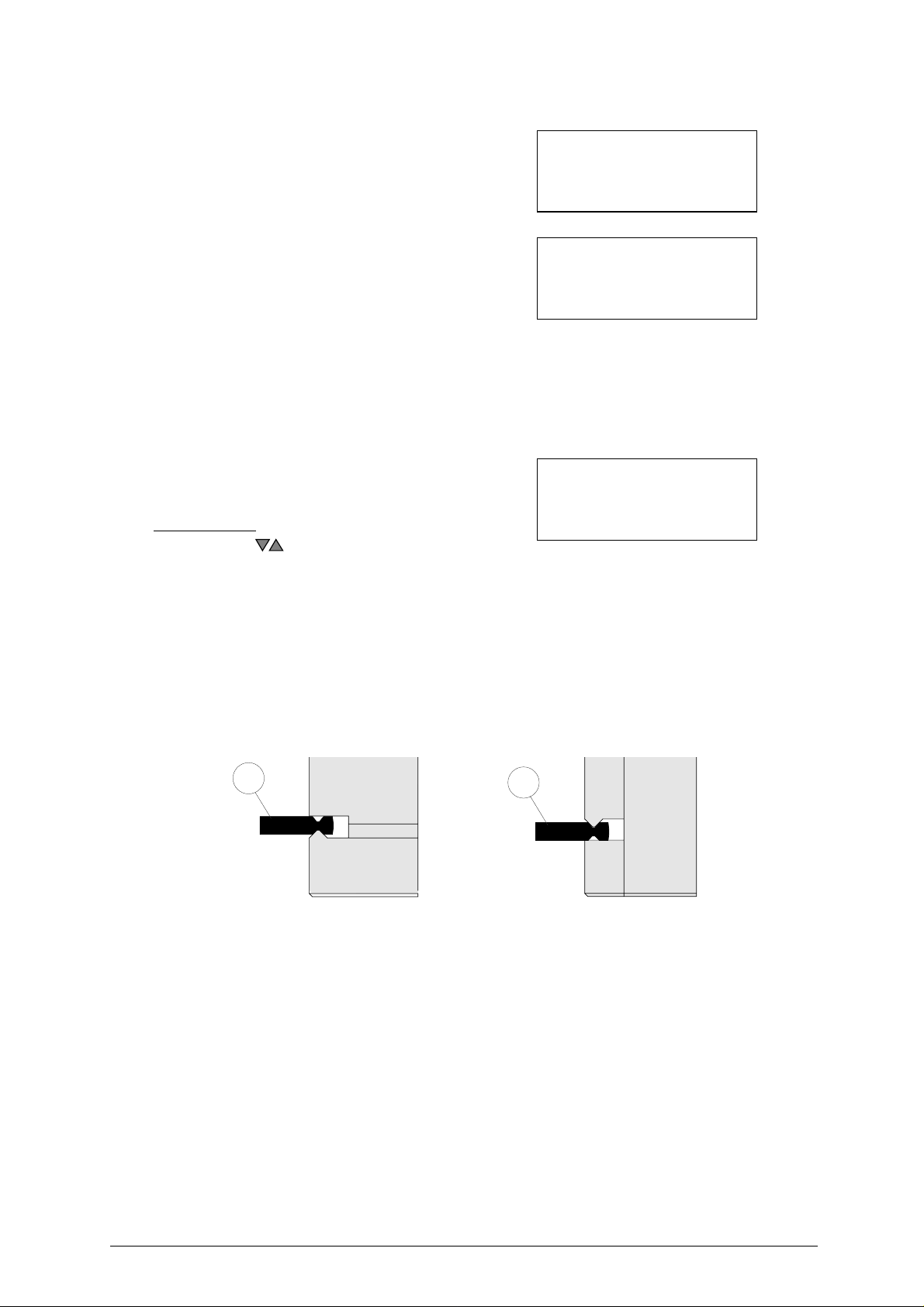
ATTENTION: make sure that the (Z3) template is properly
inserted into side C of the V100 clamp (see
fig. 23).
• turn the V100 clampto side D, insertthe (Z3)
template into the clampand proceed with the
settings, following the same procedure
described for side A.
ATTENTION: make sure that the (Z3) template is properly
inserted into side D of the V100 clamp (see
fig. 23).
Operational keys:
use thearrowkeys to directly select the sideoftheclamp
you intend to set.
START: to begin the setting procedure.
STOP: to interrupt the setting procedure.
ATTENTION: after calibrating all sides of the V100 clamp:
- remove the (Z3) template from the V100
clamp.
- remove the (Z1) template from the cutter
shaft replacing it with a cutter.
V100 SIDE C
Adjustment SIDE C
X = +00 Y = +00
To calibrate [START]
V100 SIDE D
Adjustment SIDE D
X = +00 Y = +00
To calibrate [START]
Fig. 23
Z3
side
C
Z3
side
D
28 Copyright Silca 2002
Page 33
Operating manual - English UNOCODE 299
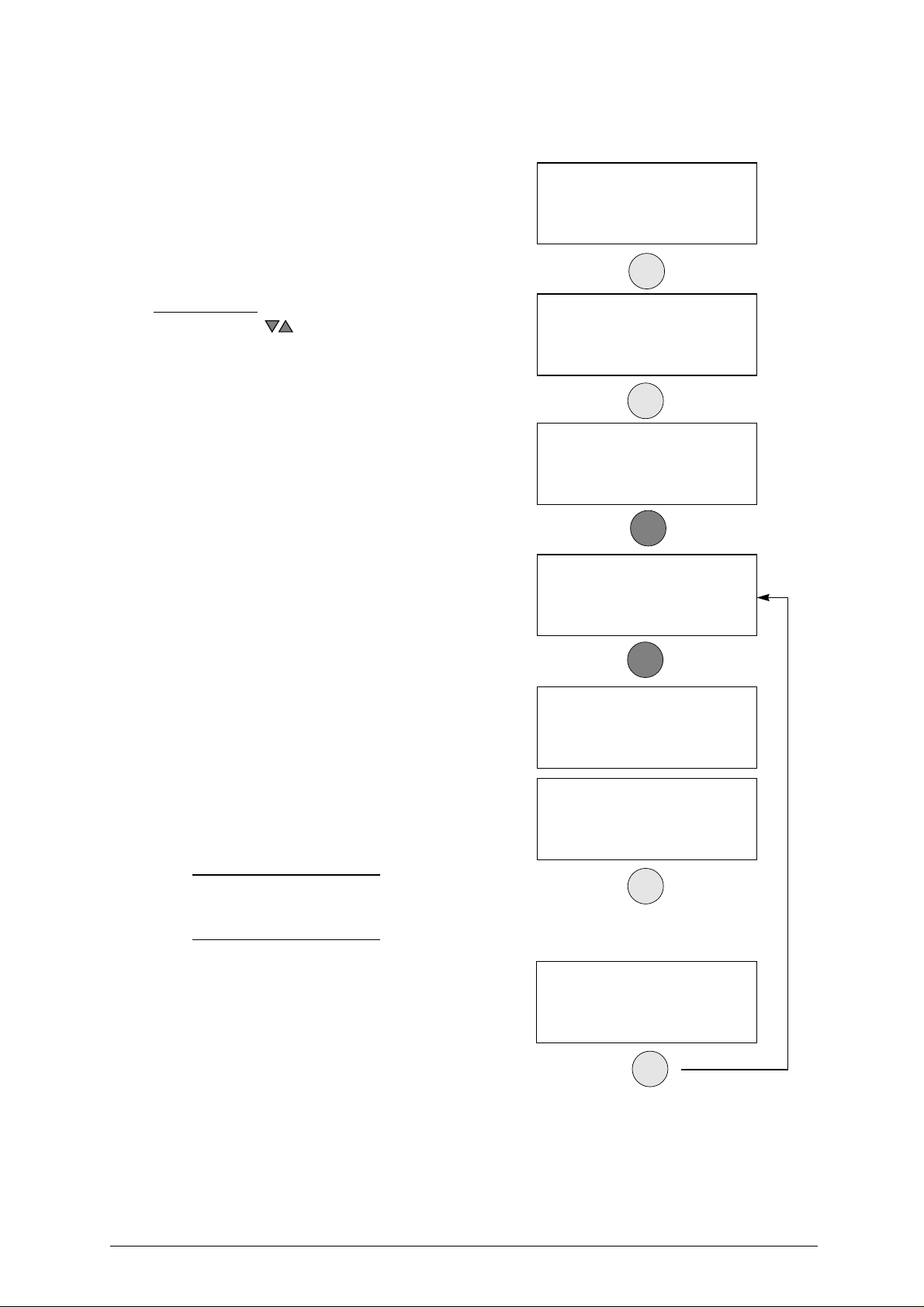
5.5.2 CALIBRATING CUTTERS
For this procedure always use side A of the
V100 clamp.
According to the cutter speed (determined by
fitting the pulleys in the way described in ch.4.7,
page 17) andmaterial (chosen fromthe ‘Options
– cutter material’ menu on page 36) the list will
show all the HSS or hard metal carbide cutters
(distinguished by the suffix ‘W’).
1) enter the “cutters” menu #2.
Operational keys:
use the arrow keys to move the cursor to select the
required cutter and press ENTER.
2) fit the selected cutter to the machine.
1 - Clamps
2 - Cutters
3 - Adaptors
ENTER
Cutters
00 - U01
01 - 01
02 - 02
ENTER
00 - U01
Adjustment:
Y = +00
To calibrate [START]
3) fit abrand new (Z3) templateon side A ofthe
V100 clamp.
4) close the shield and proceed with setting the
cutter by pressing START.
- the display shows the differences from
the theoretical values.
NOTE: the setting will be accepted only if the
tolerance of the cutter’s diameter
remains within a range between +10 /–
100 hundredths of a mm.
- if the tolerances exceed the accepted
range the machine’s display will show
an error message:
- carefully follow the instructions and repeat the procedure
ATTENTION: Once this operation is completed the (Z3)
template must be discharged of; contact
with the cutter skims the surface of the
template therefore it would cause errors if
used for future settings.
START
00 - U01
Install the Z3 template.
See operating manual.
[START]
START
00 - U01
Detection
in progress!
00 - U01
Adjustment: +002
Save data?
No = Stop Yes = ENTER
ENTER
Exceeded setting
tolerance limit
See operating manual
ENTER
Copyright Silca 2002 29
Page 34
UNOCODE 299 Operating manual - English
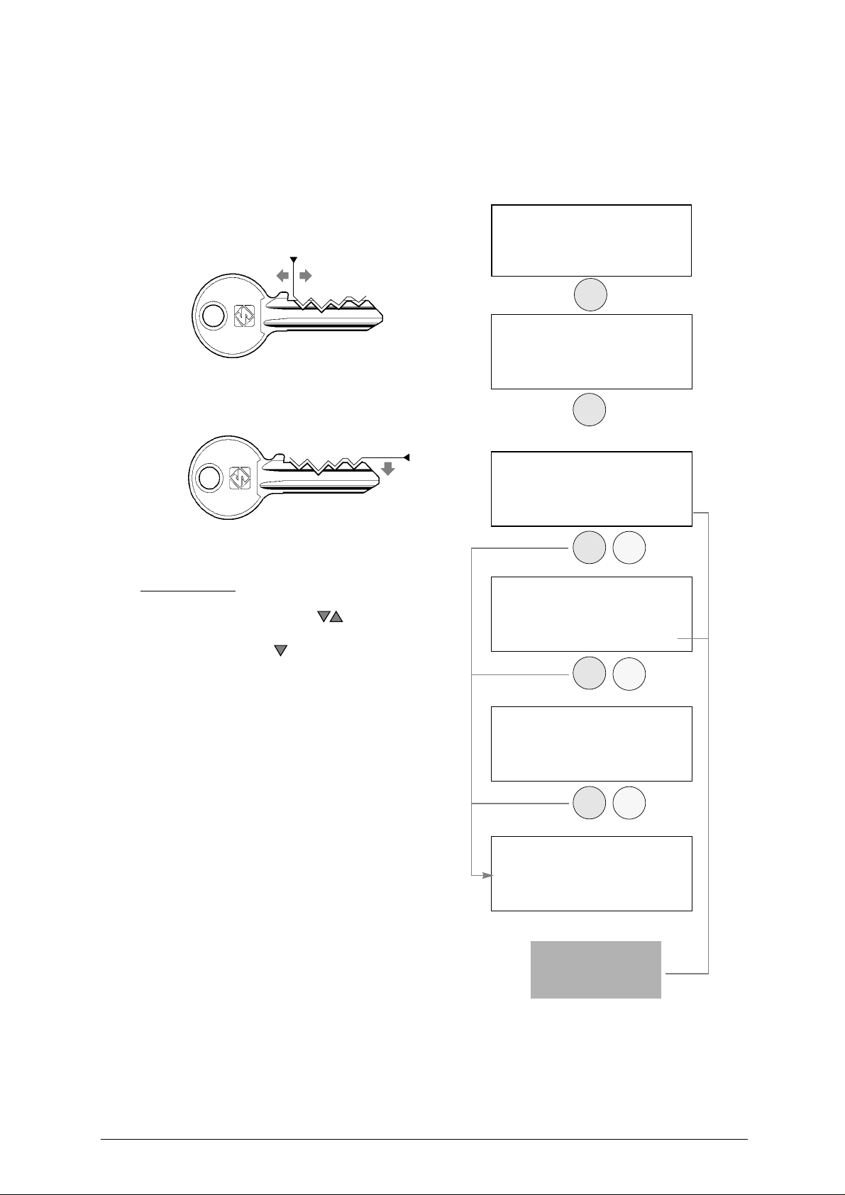
5.5.3 MANUAL ADJUSTMENTS
(CLAMPS –CUTTERS -ADAPTERS)
The operator may carry out manual adjustments by entering new X and Y parameter values.
ATTENTION:
such adjustments should be made only when the automatic setting has already been carried out
(where applicable)
Adjustments can be made within a range
between +30 and –30 hundredths of a mm.
To adjust clamps and adapters, the positive
values of X will give the result shown in fig. 24.
.
1 - Copy by code
2 - List of codes
3 - Queue from PC
+-
4 - Calibrations >>
ENTER
1 - Clamps
2 - Cutters
Fig. 24
For adjustments to cutters, clamps and
adapters, the positive values of Y will give the
result shown in fig. 25.
+
3 - Adaptors
ENTER
Clamps
V100
-
Adjustment SIDE A >>
X = +00 Y = +00
To calibrate [START]
Fig. 25
ENTER
ENTER
STOP
STOP
The >> symbol indicates that the selected clamp has more than
one side.
Operational keys:
place thecursornexttothe parameter and enter the adjustment
figure using the SHIFT + arrow keys .
CLEAR: to zero out adjustments
ENTER or down arrow key : to move the cursor from the X
to the Y axis settings
ENTER: press in the final entry field to quit the menu.
to exit the menu
STOP:
SHIFT+ENTER:
when making manual adjustments
to go from one side of the clamp to another
.
Cutters
00 - U01
Adjustments:
Y = +00
To calibrate [START]
Adaptors
B1
Adjustments:
X = +00 Y = +00
ATTENTION: if the STOP key is pressed, thenew settings
will be lost. If so, only the previous setting
values will remain valid
30 Copyright Silca 2002
ENTER
STOP
Save
adjustments
?
No = STOP Yes = ENTER
Press START only if you
intend to proceed with
automatic calibration.
Page 35

Operating manual - English UNOCODE 299
5.6 [5] MAINTENANCE
1) enter the ‘Maintenance’ menu #5.
Operational keys:
use the keys to move the cursor to the option required
and press ENTER or directly press the numbered key corresponding to the option number.
5 - Maintenance
6 - Options
ENTER
5.6.1 TESTS
There is an on board TEST menuthat should be
used to verify the cause of any breakdown that
may occur to the machine.
• Test 1:
Carefully follow the instructions on the machine’s display. Check that the X axis carriage moves.
ATTENTION: during this test function all end of run controls are disactivated; avoid moving the carriage upagainst
its mechanical stops.
NOTE: if the motor does not start, contact Silca’s Technical Assistance Dept.
X AXIS MOTOR
1 - Test
2 - Machine ‘0’ point
• Test 2:
Carefully follow the instructions on the machine’s display. Check that the Y axis carriage moves.
ATTENTION: during this test function all end of run controls are disactivated; avoid moving the carriage upagainst
its mechanical stops.
NOTE: if the motor does not start, contact Silca’s Technical Assistance Dept.
• Test 3:
Carefully follow the instructions on the machine’s display. Check that the cutter motor is working.
NOTE: if the cutter motor does not turn, contact Silca’s Technical Assistance Dept.
• Test 4:
-
the machine’s display should show ON when the carriage is drawn away from the machine (towards the operator)
-
the machine’s display should show OFF when the carriage is pushed all the way in towards the
machine
NOTE: if the ON/OFF transition is not made, contact Silca’s Technical Assistance Dept.
• Test 5:
-
the machine’s display should show OFF when the carriage is moved all the way to the right
-
the machine’s display should showON when the carriage ismovedall the way to the left (towards
the cutter
Y AXIS MOTOR
CUTTER MOTOR
X AXIS SENSOR
.
.
Y AXIS SENSOR
.
).
NOTE: if the ON/OFF transition is not made, contact Silca’s Technical Assistance Dept.
• Test 6:
Lift and lower the protective shield checking that the machine’s display indicates OFF to ON
NOTE: if the ON/OFF transition is not made, contact Silca’s Technical Assistance Dept.
PROTECTIVE SHIELD MICROSWITCH
Copyright Silca 2002 31
.
Page 36

UNOCODE 299 Operating manual - English
• Test 7:
Useanymetalconductor to contact clamp to cutter,checkingthatthemachine’sdisplay indicates OFF
to ON
NOTE: if the ON/OFF transition is not made, check the brushes or contact Silca’s Technical Assistance
• Test 8:
One at a time, press allthekeys(except STOP) checking that an asterisk(*)appearsfor each key pressed.
Press the STOP key for last.
NOTE:
ELECTRIC CONTACT
.
Dept.
KEYBOARD
if the asterisk does not appear,
contact Silca’s Technical Assistance Dept.
• Test 9: DISPLAY
All points on the display should be obscured
NOTE: if this is not so, contact Silca’s Technical Assistance Dept.
• Test 10:
Check that the machine’s display indicates OFF
Fit the special(Z4) serial test connector (accessories provided) to the machine’s serialport,checking
that the machine’s display indicates OFF to ON
NOTE: if the ON/OFF transition is not made, contact Silca’s Technical Assistance Dept.
SERIAL PORT
.
.
.
32 Copyright Silca 2002
Page 37
Operating manual - English UNOCODE 299
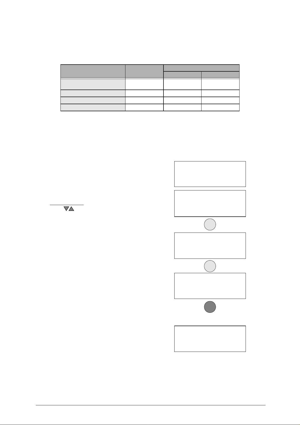
5.6.2 MACHINE ZERO POINTS
With the useof regulating templates (Ch.1.5"Accessories provided", page7) the machine provides a ‘selfsetting’ procedure. These procedures must be carefully carried out following the descriptions and
illustrations indicated below.
EVENT MACHINE ZEROES CALIBRATING (Ch. 5.5, page 26)
CLAMPS CUTTERS
Replacement of
the electronic board
Replacement of sensors YES NO NO
Replacement of the cutter shaft YES NO NO
Replacement of the ball screws YES NO NO
PRELIMINARY OPERATIONS
1)
turn the machine off and unplug it from its power supply cable
2)
remove the bottom panel
3)
plug the
4)
turn the machine on and carry on with the procedures described on
machine’s power supply cable
(ch.7.9, page 50).
YES
(see ch.7.6, page 48)
back in
YES
(see ch.7.6, page 48)
to place.
(see ch.7.6, page 48)
.
page 33.
YES
Procedure:
enter the “Maintenance” #5
1)
2)
select “Machine zero points” #2
Operational keys:
use the keys to move the cursor to the option required
and press ENTER or directly press the numbered key corresponding to the option number.
3)
remove the V100 clamp from its support
4)
insert the (Z2) template, the clamp’s
.
.
.
bushing and secure them with the clamp’s
knob
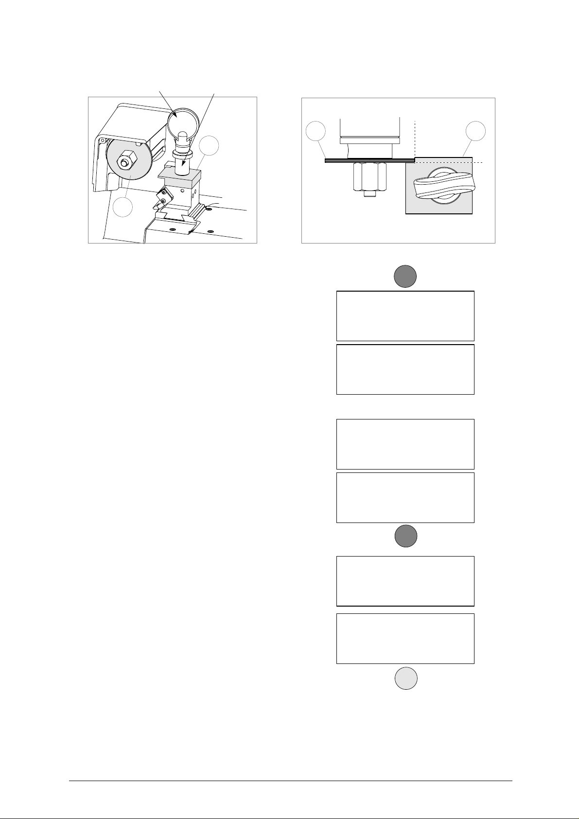
(fig. 26).
5)
remove the cutter (ch
insert the (Z1) templateinto place (
manually move the X and Y axis up until
6)
.4.6, page 16)
fig. 26).
and
the (Z1) and (Z2) templates make contact
(see fig. 26 - top view).
lower the protective shield and press
7)
START
.
5 - Maintenance
6 - Options
1 - Test
2 - Machine ‘0’ point
ENTER
Install Z1 & Z2
templates.
See operating manual.
ENTER
Move X and Y axis
up until contact is made
See operating manual.
START
ATTENTION:
check that both the (Z2) and (Z1) templates
make perfect contact (fig. 26). If this does
not occur the display will show an error
message
.
-
the machine will take the X and Y
axes to a predefined position
.
Copyright Silca 2002 33
TEMPLATE E R R O R
No contact made.
See operating manual.
Page 38
UNOCODE 299 Operating manual - English
Fig. 26
clamp’s knob
Z1
Regulating the Y axis sensor:
•
raise the protective shield
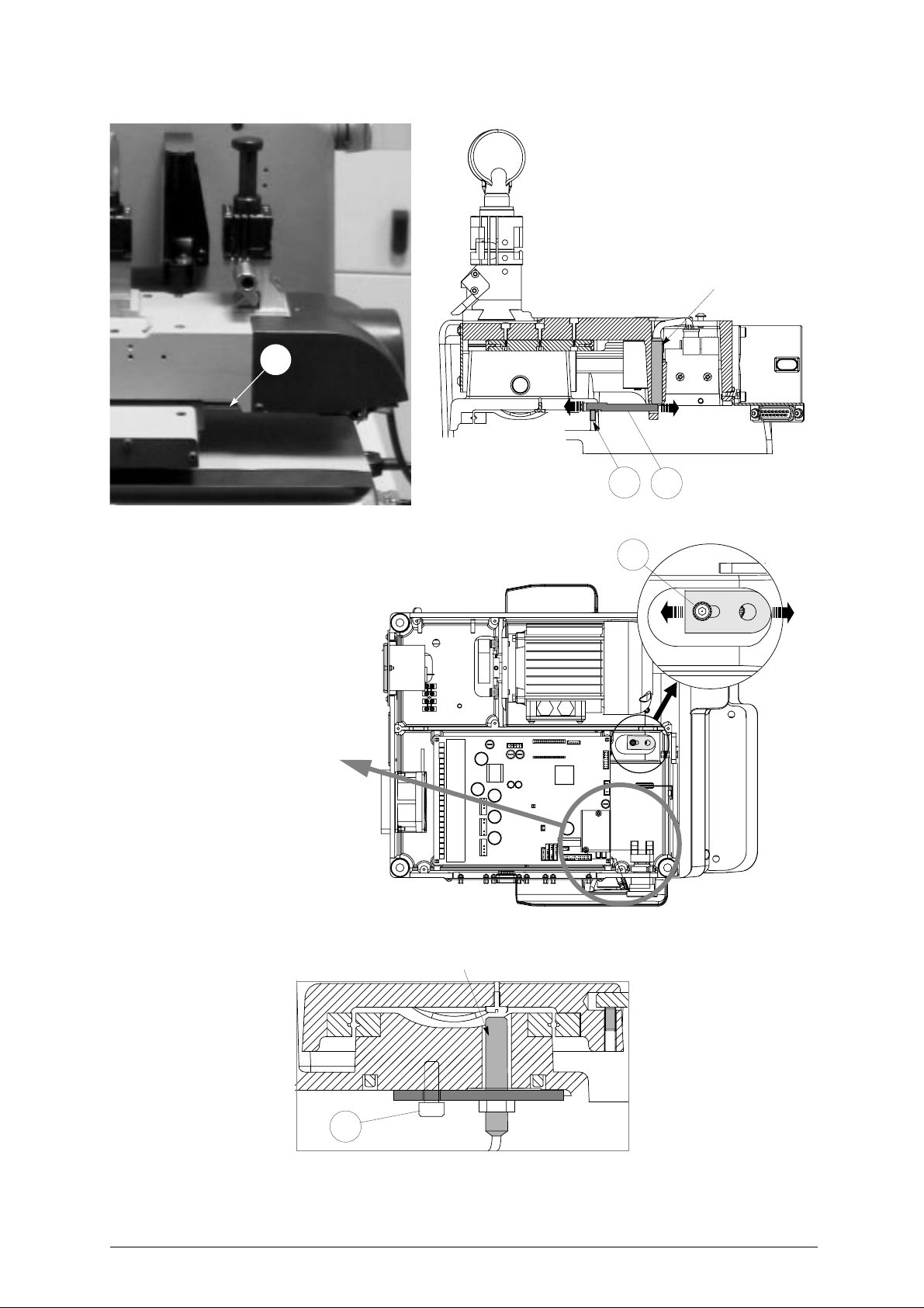
• use the providedallen key toloosen the (C1)
grub screw; manuallyrotate the (C2) rod(fig.
27) in both directions upuntilthe changeover
point from OFF to ON is found.
•
tighten the (C1) grub screw (fig. 27) to
secure the rod
clamp’s bushing
Z2
.
.
X
Z2
top view
START
Pos. sensors.
ICX = OFF ICY = OFF
See operating manual.
[START]
Pos. sensors.
ICX = OFF ICY = ON
See operating manual.
[START]
Z2Z1
Y
Regulating the X axis sensor:
•
carefully tip the machine over
• remove the bottom panel by unscrewing all8
securing screws.
• loosen the (C3) screw (fig. 28, page 35) that
secures the sensor support plate. Manually
move the sensor support plate up until the
display’s description goes from OFF to ON.
• tighten the (C3) screw (fig. 28, page 35) to
secure the plate back into place.
•
re-position the machine back on its
workbench and lower the protectiveshield
•
press
START.
-
the ‘machine’s zero’ settings are detected by electric contact
8)
when the operation has been completed,
the displaywill show the measured quotes
9)
press ENTER to save the settings
ATTENTION: if the STOP key is pressed, thenew settings
will be lost. If so, only the previous setting
values will remain valid.
.
.
.
Pos. sensors.
ICX = OFF ICY = OFF
See operating manual.
[START]
Pos. sensors.
ICX = ON ICY = ON
See operating manual.
[START]
.
START
Zero detection
in progress!
.
Measured quotes:
X = 4444 Y = 3333
Save measurements?
No = STOP Yes = ENTER
ENTER
34 Copyright Silca 2002
Page 39
Operating manual - English UNOCODE 299
Y axis sensor
C2
C1
C2
Fig. 27
ATTENTION: if it is necessary
to work close to this area with
the machine turned on (e.g. to
regulate the X axis sensor)
take great care not to touch
any components on the
machine’s electronic boards
as it is connected to 230 /110
Volts.
Fig. 28
C3
bottom view
X axis sensor
Fig. 29
C3
Copyright Silca 2002 35
Page 40
UNOCODE 299 Operating manual - English
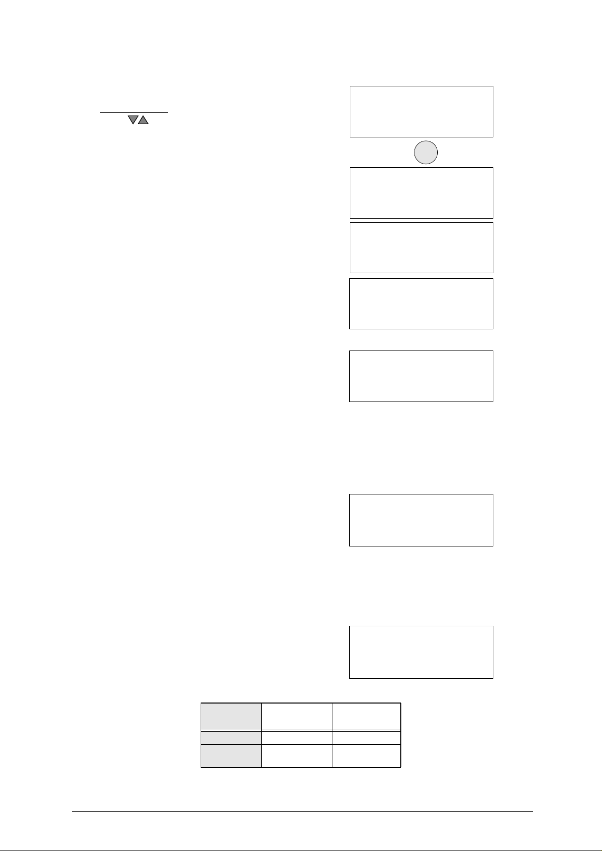
5.7 OPTIONS [6]
1)
Enter ‘Options’ menu # 6
Operational keys:
use the keys to move the cursor to the option required
and press ENTER or directly press the numbered key corresponding to the option number.
.
5 - Maintenance
6 - Options
ENTER
1 - Serial No.
2 - Cutter material
3 - Cutting speed
4 - Carriage speed >>
5 - Min. distance
6 - Modify keys stop
7 - Preference
8 - Language >>
10-Invers. keyboard
11-Cutting check
12-Protected Systems
1-
S
ERIAL NUMBER
displays the machine’s serial numberthatshould
correspond to the serial No that is stamped on
the back of the machine.
Model
:
type of Unocode.
Keys cut
SW Version
:
numbers of keys cut.
:
Software version of the program installed on the
machine.
2-C
UTTER MATERIAL
The option ‘cutter material’ shows all the HSS
(enter 0) or hard metal (enter 1) cutters.
By inverting the pulleys two cutter rotation
speeds can be obtained:
• low speed for HSS tools
•
high speed for hard metal carbide tools
Inversion of the pulleys gives the first or second
speed according to the method described in
ch.4.7, page 17.
3-
C
UTTING SPEED
Corresponds to the carriage advancement
speed during the key cutting operation:
On the basis of the cutter material selected,
speed can be altered as shown in the table.
:
:
:
Ser. n: 153214523123
Model : 299
Keys cut : _ _ _
SW Version : _._._
Cutter Material = 0
(0 = HSS )
(1 = Hard metal )
See operating manual
Cutting speed
HSS Hd. Met.
300 400
(100-400) (200-700)
cutter metal
HSS 300 100-400
Hard metal
carbide
36 Copyright Silca 2002
Recommended
speed
400 200-700
Speed Range
Page 41
Operating manual - English UNOCODE 299
4-C
ARRIAGE APPROACH SPEED
This is the speed at which the carriages move
towards the cutting area, before starting the
cutting cycle.
We recommend to operate the machine with the
speed that is set (4000). If required, the operator
can adjust the carriage approach speed from a
minimum of 1000 to a maximum of 5000.
5-
M
INIMUM DISTANCE
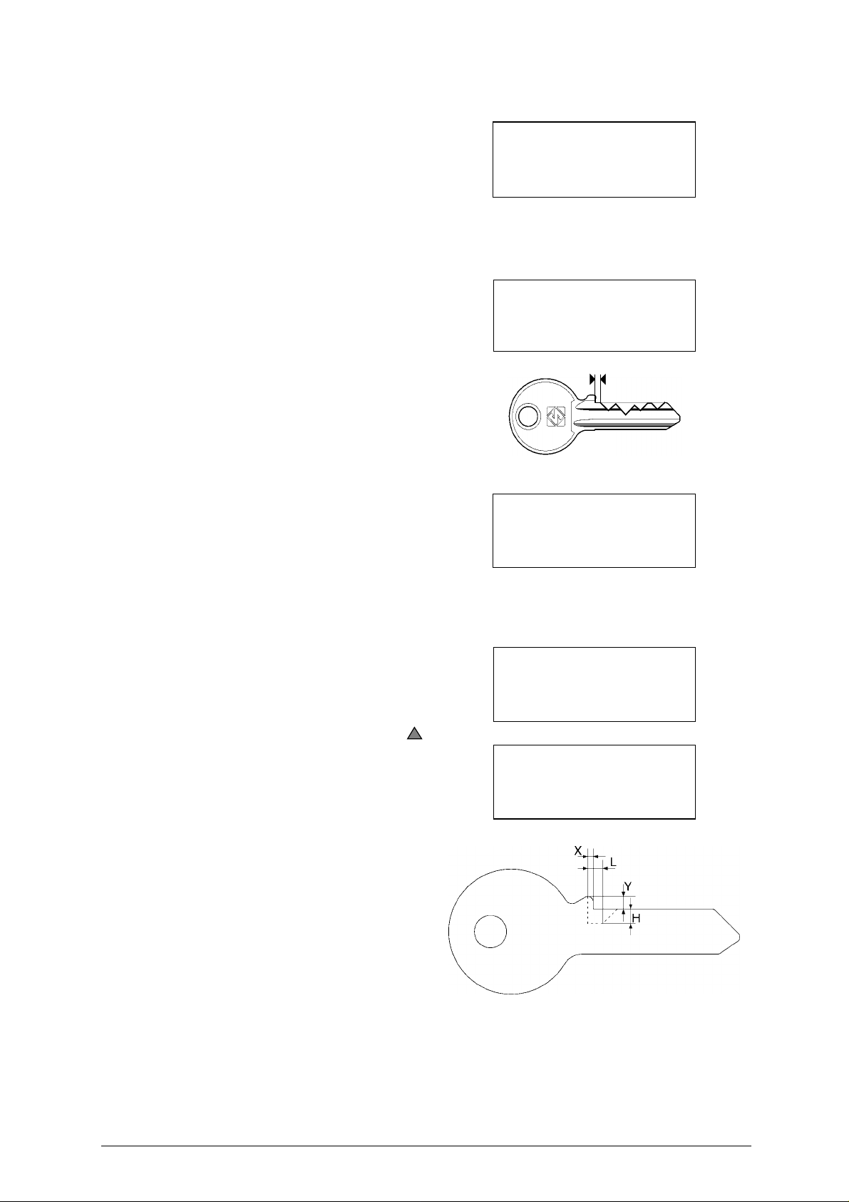
The number shown on the machine’s display
represents the X axis distance between the key
blank shoulder and the beginning of the first cut
(fig. 30).
This function is extremely important with keys
that require cuts on both sides as it ensures
precise positioning on the key 2nd side.
The set figure is 50 hundredths of a mm, which
can be varied between min.0 - max. 99
hundredths of a mm.
ATTENTION: settings that are too high may render
precise cuts impossible, with the following
message on the display:
:
:
Carriage approach
speed = 4000
(1000 - 5000)
Min. distance
of cut from key stop = 50
(0 - 90)
Fig. 30
Min. Parameter of
DISTANCE FROM STOP
is incompatible with
selected card!
6-M
ODIFY KEYS STOP
Normally the machine does not require key
shoulder stop adjustment.
If required, it is possible to modify the key’s
shoulder according to the modification made to
the key shoulder (fig. 31).
If the operation is confirmed(with SHIFT+ ), 4
items are required:
thickness X:
measurement of the shoulder stop to be cut is
expressed in hundredths of a mm (min.0 max.99).
height
Y:
height of the shoulder read on the key using a
calliper, expressed in hundredths of a mm. E.g.:
• Y = 3 mm = 300 hundredths
depth H:
depth of the part to be removed, expressed in
hundredths, referred to the measurement of the
key blank.
length L:
movement of the cutter axis referred to X.
:
Modify key stop
Enabled = YES
Thickness X = 0
Height Y = 300
Depth = H = 100
Length = L = 50
Fig. 31
Copyright Silca 2002 37
Page 42

UNOCODE 299 Operating manual - English
7-P
REFERENCES
work parameters are chosen from this menu
Inches or millimetres
choose the measurements you intend to work
with (mm = millimetres, inch. = inches).
:
.
:
Start-up menu
choose the function in the Main menu that you
would like to appear first when the machine is
turned on:
Attention: press the “CLEAR/COPY” keytovoid
any selection made and to select the (*) main
menu function.
Quick menu
when enabled (=1) some operational functions
will be skipped (if admissible).
e.g. when ‘0’ is set, the display shows the following
when the machine is turned on:
8-
enter the number that corresponds to the
language you intend to work with
9-O
function not available.
:
* = Main menu
1 = Copy by code
2 = List of codes
3 = Queue from PC
4 = Calibrations
:
L
ANGUAGE
PTICAL READER
:
.
:
mm [0] inch. [1] = 0
Start Menu = * (0-3)
Quick Menu = 0 (0-1)
ORIGINAL on right.
Clamp = 100/_? (ABCD)
Pos. = 0 (0-4)
Dist.= 000 [START]
Select language = 2
1 : Italiano 2 : English
3 : Deutsch 4 : Français
5 : Español
10 - K
EYBOARD INVERSION
This function inverts the alphanumerical
keyboard (numbers to letters (fig. 9, page 12).
With “Inversion keyboard” disactivated (0) :
• to digit number 1: press
• to digit the letter H: press SHIFT +
With “Inversion keyboard” enabled (1) :
• to digit number 1: press SHIFT +
• to digit the letter H: press
NOTE: this function can be carried out from the main menu“ Copy by code” and/or “List of codes” .
38 Copyright Silca 2002
1
H
1
H
1
H
1
H
Inversion keyboard
function = 0
(1 - enabled)
see Operating manual
Page 43

Operating manual - English UNOCODE 299
11 - C
UTTING CTRL
This option is used toenable and disable control of
the combinations included in the data card, by
pressing the SHIFT + keys.
Default is YES, i.e. permanent control of the
combinations entered to check compatibility with
the cutting path.
The control function followsgivenrules that prevent theoperatorfrom creating keys whoseoperationis not
guaranteed.
12-L
IST OF ENABLED SYSTEMS ACTIVATED AND REMOVAL OF AN ACTIVATION(PROTECTED
S
YSTEMS
To read the list of data cards enabled, select menus 6-12.
Select the item in menu 1 to see the Machine
Identification Number.
)
.:
Enable check on
excluded
combinations: YES
See operating manual
PROTECTED SYSTEMS
1 - Machine ID
2 - Enabled Systems
Select the item in menu 2 to see the list of Enabled
Systems:
ENABLED SYSTEMS
1: CARD 121
2: CARD 234
To delete an enabled system, place the cursor on
the line to be eliminated and press the CLEAR key.
3: CARD 20
Copyright Silca 2002 39
Page 44

UNOCODE 299 Operating manual - English
5.8 ERROR MESSAGES
• The selected data card is for a different
clamp from the oneinstalled on the machine.
Install proper clamp.
• The entered data card number is not
available in the machine’s data base.
• The entered cuts cannot be carried out (see
ch.5.2.1, page 20)
This message appears when the cutter
•
must be changed with one that is
compatible to the type of cuts required for
the entered data card number
This clamp is not available in the
•
machine’s data base
.
.
Data card not
compatible with
clamp installed!
Data card
not available!
Non-feasible
combination!
ATTENTION !!
Install cutter:
U01
Clamp not
available!
This cutter is notavailable in themachine’s
•
data base
• This adapter is not
machine’s data base
• The entered data card number requires a
type of cut that is not available in the
machine’s data base.
• The minimum distance from the key stop
position overlaps the first cut on the key
(ch.5.7, page 36).
• This message appears when the cutter is
unable to identify the keys measurements
when cutting by means of electric contact.
.
available in the
.
Cutter not
available!
Adaptor not
available!
Type of cut
not available!
MIN. Parameter of
DISTANCE FROM STOP
is incompatible with
selected card!
POSITION ERROR
Key not
properly installed!
40 Copyright Silca 2002
Page 45

Operating manual - English UNOCODE 299
• During the cutting cycle one or more depth
exceeded the maximum limit. These depths
are automatically aligned to the maximum
permitted depth.
• The automatic setting revealed a variation
that exceeded the permitted nominal figure
setting reference. Carefully repeat the
setting procedure.
• During the setting of the “machine’s zero
points” there is a contact failure between the
two templates (see ch.5.6.2, page 33).
• Indicates that the entered function is not yet
available.
• The electronic control board has exceeded
the maximum permitted temperature. Check
the cooling fan (ch. 7.1 "Trouble shooting",
page 43).
ATTENTION
Depth limit
exceeded!
Exceeded setting
tolerance limit
See operating manual
TEMPLATE ERROR
no contact made.
See operating manual
Non-feasible
function !
TEMPERATURE ALARM
Turn the machine off!
• Indicates that the fuse has blown due to a
short circuit in an inlet or outlet (ch. 7.1
"Trouble shooting", page 43).
• Indicates a short circuit in port P (IN/OUT)
(ch. 7.1 "Trouble shooting", page 43).
• Indicates that the fuse has probably blown
(ch. 7.1 "Trouble shooting", page 43).
• Indicates a fault on the electronic control
board.
• The Machine ID has not been set. In such
cases access cannot be gained toProtected
Systems until the Machine ID is set. Select
menu 6-12-1 and check that the Machine ID
is different from0. To set Machine ID ask for
a Software update valid for your machine
(machine internal program version higher
than or the same as 2.0.078) and install with
the SILCA WinTransfer Program or SILCA
Code Program.
I/O POWER ALARM
Check fuse F4 !
DIGITAL OUTLET
PROTECTION ALARM
Turn the machine off !
CUTTER MOTOR
ALARM
Check fuse F1 !
CUTTER MOTOR
ALARM
Fault on motor circuit !
ERROR
Machine ID
not defined
See operating manual
Copyright Silca 2002 41
Page 46

UNOCODE 299 Operating manual - English
6 CLEANING
• keep the operationalparts of themachine as clean as possible by brushing away the chippings
in areas where they accumulate during cutting operations.
• under no circumstances must compressed air be used to clear the work zone of chippings as
this will blow them onto the moving parts.
• Never use oily products or thinners for cleaning painted surfaces, clamps, electrical or
electronic connections.
42 Copyright Silca 2002
Page 47
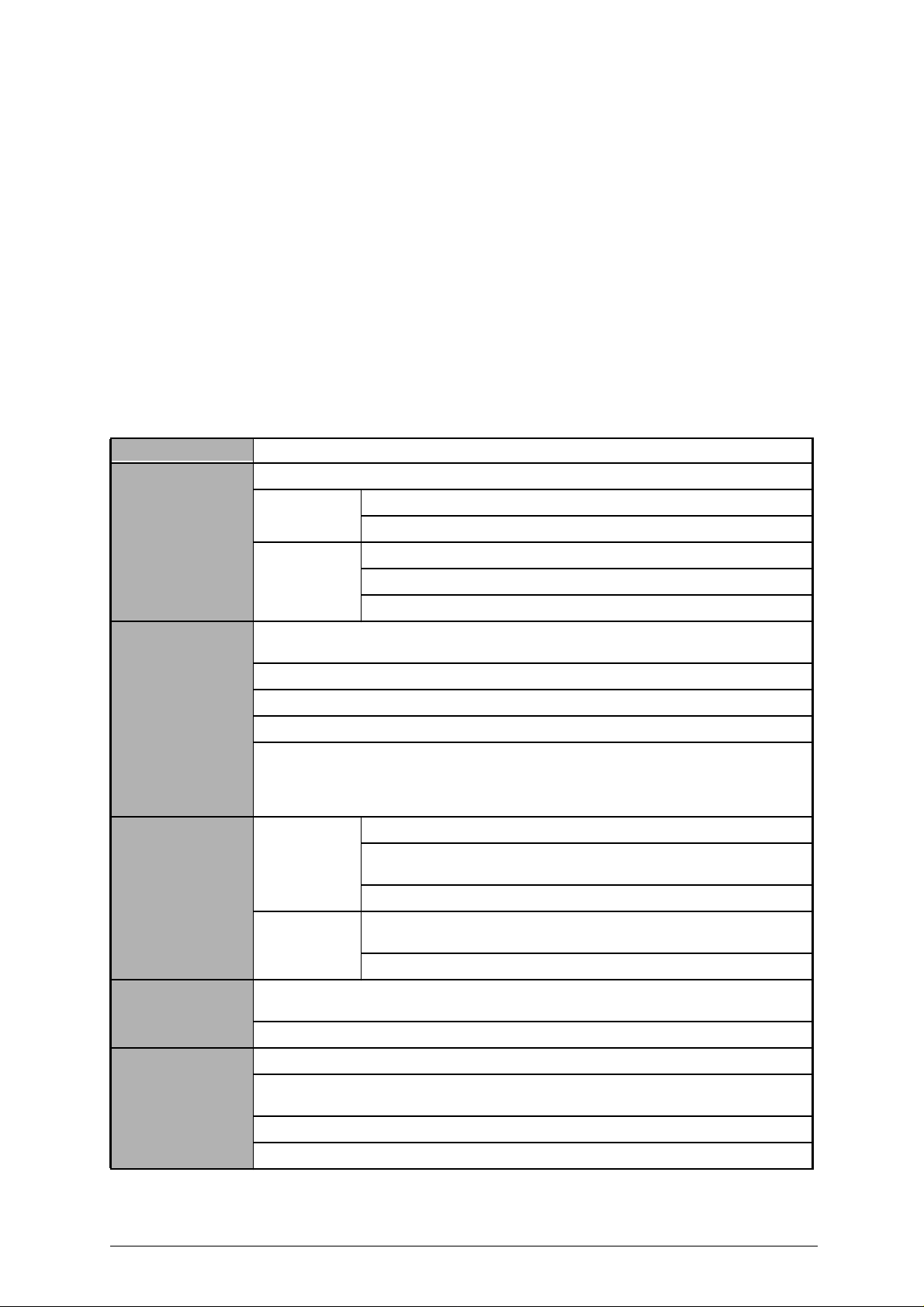
Operating manual - English UNOCODE 299
7 MAINTENANCE
ATTENTION: for repairs or replacement of partsfor maintenance, the ‘CE’ mark is guaranteedonlyif original spare
parts provided by the manufacturer are used.
Although the UNOCODE 299 key-cuttingmachine does not require special maintenance, it is advisable to
check and, if necessary, replace the parts subject to wear and electric/electronic parts (fuses, circuit
boards, etc.) in the event of faulty operation.
ATTENTION: for normal servicing of the burnished mechanical parts, we recommend using lubricants or
protective oil, e.g. WD40 or similar. Do not apply to the parts used for electrical contact (clamps,
decoders, cutters, gauging templates, etc.). Do not contaminate the electronic parts with the oil.
Replacement is simple and can be carried out by the operator consulting the instructions.
Before starting any type of maintenance (controls or replacements), read the instructions below:
• never carry out maintenance with the machine switched on
• always remove the main power supply cable
• strictly follow all the instructions in the manual
• use original spare parts (see Spare Parts sheet provided).
7.1 TROUBLE SHOOTING
FAULT PROBABLE CAUSE
Machine is on, with no
message on its display.
check to see if the back fan is working
not working: a) emergency button activated
b) general fuses in the power socket are faulty
working: a) fuse F3 on electronic control board is faulty
b) connection wire between display and electronic circuit board loose
cutter motor not
working.
X, Y and B axes motors
are not working.
Protective shield is
closed but the display
reads “‘close shield”.
Keyboard not working
(partially or completely)
c) defective display
a) the closed protective shield is not making proper contact with the safety microswitch (fig.
33).
b) the F1 fuse on the electronic control board is faulty
c) motor wire not properly attached to the connector
d) defective electronic control board
e) motor cut-off
WARNING: this may derive from inappropriate or heavy use of the key-cutting machine or a
fault with the motor itself. DO NOT USE THE MACHINE and call Technical Silca Dept. to
determing the cause of activation of the cut-off.
None of the
motors working:
a) fuse F2 on the electronic control board faulty
b) the wiring between the transformer and electronic control board is
loose or the connector is not seeded properly.
c) defective electronic control board
Only one
motor is not
working:
a) the connection wires between the motor and the electronic control
board are loose or the connector is not seeded properly
b) defective electronic control board
a) the closed protective shield is not making proper contact with the microswitch (D3) (fig.
33)
b) the F4 fuse on the electronic control board is faulty
a) the keyboard connector is not properly connected to the interface board (fig. 32)
b) the wiring between the keyboard/display unit and electronic control board is not properly
attached to the relative connectors
c) defective keyboard
d) defective electronic control board
Copyright Silca 2002 43
Page 48
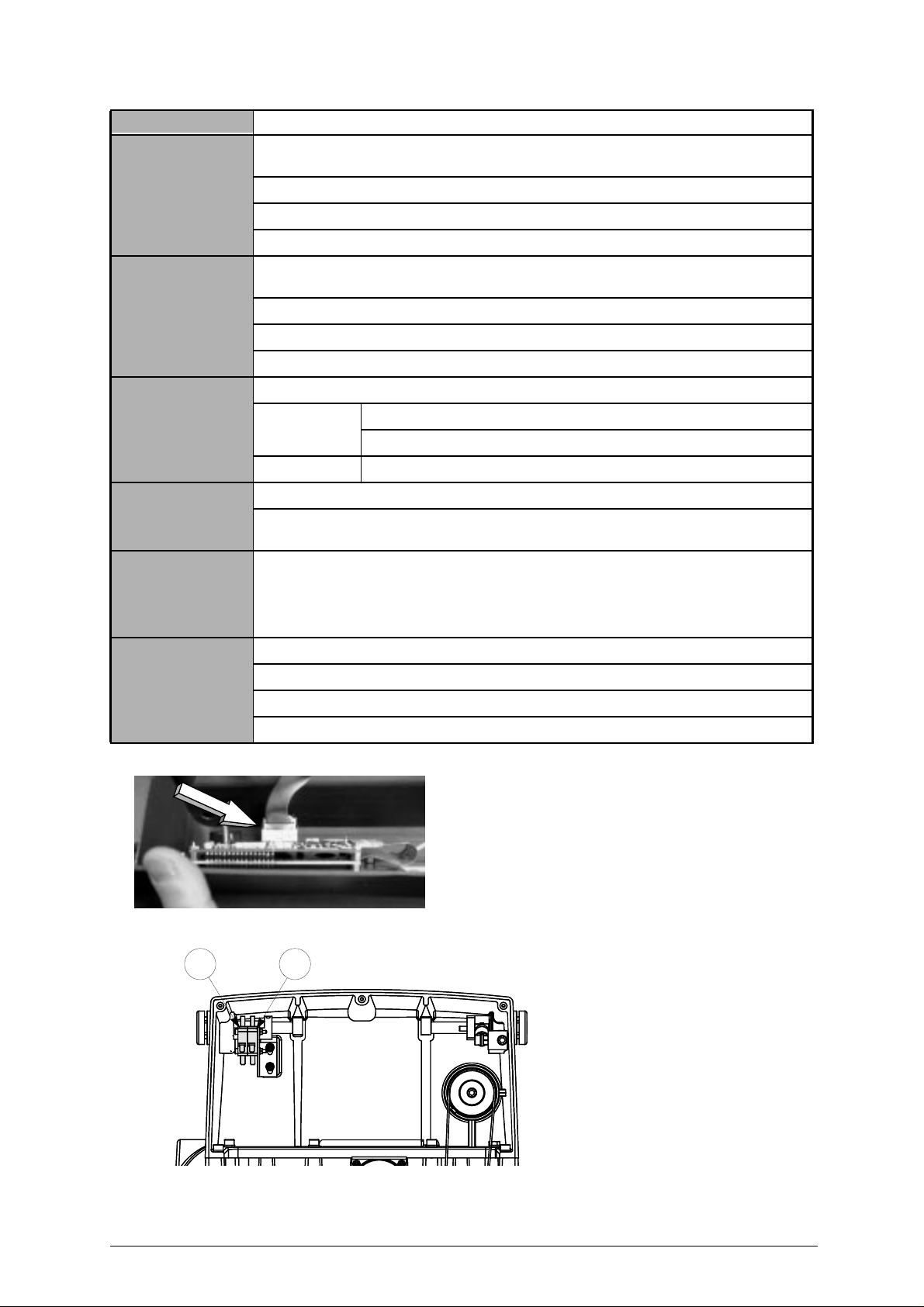
UNOCODE 299 Operating manual - English
FAULT PROBABLE CAUSE
Electric contact not
working (during
calibrating or cutting).
a) wiring between the J14 connector on the electronic control board and cutter shaft is loose
or disconnected
b) wiring inside the Y axis carriage is not seeded properly or disconnected
c) defective electronic control board
d) wear on the brushes (ch. 7.11, page 53)
Key-cutting machine fails
to communicate with
computer.
a) wiring between 9-pin serial port and electronic circuit board not seeded properly or disconnected
b) serial cable between key-cutting machine and computer is faulty
c) computer serial port is not functional
d) defective electronic control board
The display shows the
message
‘TEMPERATURE
ALARM - Turn the
machine off’.
check that the fan on the back of the key-cutting machine is working:
not working a) fan faulty
b) electronic control board faulty
working electronic control board faulty
The display shows the
message: ‘I/O POWER
ALARM – check fuse F4’.
The display shows the
message: ‘DIGITAL
OUTLET
PROTECTION ALARM turn the machine off’.
The display shows the
message: ‘CUTTER
MOTOR ALARM check fuse F1’.
a) fuse F4 on the electronic control board faulty.
b) short circuit on the inlets. To find which inlet is causing the error message, disconnect the
J7-8-14-20 connectors one at a time and check each time whether the alarm disappears.
internal fault on the electronic control board.
a) fuse F1 on the electronic control board faulty.
b) cutter microswitch on protective cover triggered or disconnected (D4) (fig. 33).
c) cutter motor wiring disconnected.
Fig. 32
Fig. 33
d) internal fault on the electronic control board.
D3 D4
44 Copyright Silca 2002
Page 49
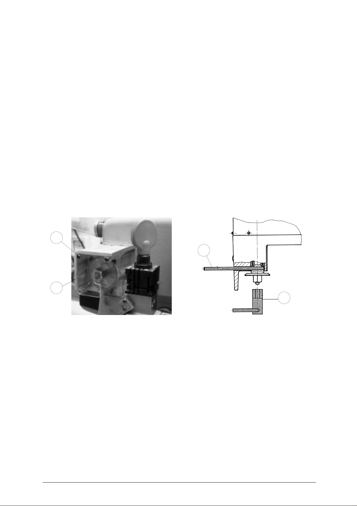
Operating manual - English UNOCODE 299
7.2 MAINTENANCE OPERATIONS
• Cutter replacement
• Belt replacement and tension adjustment
• Fuse check and replacement
• Electronic circuit board replacement
• Keyboard/display replacement
• Access to back compartment
• Access to bottom compartment
• Sensor replacement
• Brush replacement
• WIN-TRANSFER program for loading/updating the machine program
7.3 CUTTER REPLACEMENT
1) turn the machine off and unplug it.
2) remove the cutter protective shield (i) by loosening the screw (i2).
3) slide thecutter release rod (X)into the hole locatedonthe left side ofthe machines cutter shaftchassis
(fig. 34).
4) loosen the cutter locking nut (turning it clockwise) with the19 mm socket wrench (X1) provided with the
machine.
ATTENTION: the thread is left-handed (reversed).
5) replace the cutter, then tighten the nut (turning it counter-clockwise) and remove the rod from its hole.
6) place the cutters protective shield (i) back into position securing it with the screw (i2).
i2
X
i
X1
Fig. 34
WARNING: when replacing a worn cutter with a new one or with a re-sharpened cutter consult Ch.5.5 "[4]
Calibrations", page 26.
Copyright Silca 2002 45
Page 50
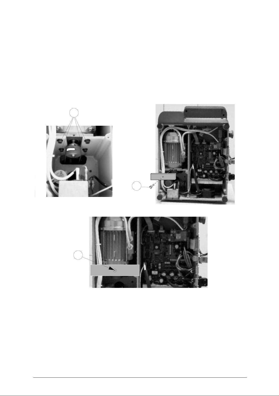
UNOCODE 299 Operating manual - English
7.4 BELT REPLACEMENT AND TENSION ADJUSTMENT
To replace the belt, proceed as follows:
1) turn the machine off and unplug it.
2) remove the back panel (ch.7.8, page 50).
3) remove the bottom panel (ch.7.9, page 50).
4) loosen the 4 screws (W) securing the motor (fig. 35).
5) remove the worn belt from the pulleys.
6) fit the new belt onto the pulleys, making sure that the direction of rotation is correct.
7) using the provided belt tension plate and the (W2) screw (fig. 35) adjust the belt’s tension by turning
the (W2) screw.
8) tighten the 4 (W) (fig. 35) screws back into place, securing the motor.
9) remount the back and bottom panel.
W
Fig. 35
Fig. 36
W2
W2
To adjust belt tension proceed as follows:
1) turn the machine off and unplug it.
2) remove the bottom panel (ch.7.9, page 50).
3) loosen the 4 screws (W) securing the motor (fig. 35).
4) using the provided belt tension plate and the (W2) screw (fig. 35) adjust the belt’s tension by turning
the (W2) screw.
5) tighten the 4 (W) (fig. 35) screws back into place, securing the motor.
6) remount the bottom panel.
46 Copyright Silca 2002
Page 51
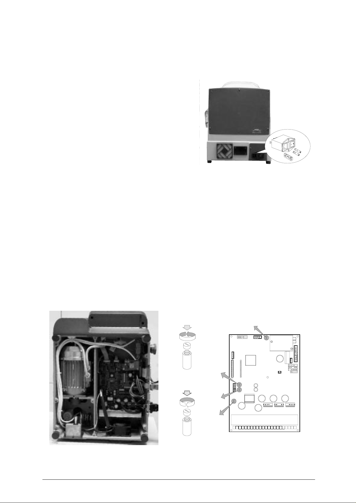
Operating manual - English UNOCODE 299
7.5 CHECKING AND/OR REPLACING FUSES
Fuses should be checked with a tester (ohmmeter, multimeter, etc.) as they may appear to be in good
condition even when they are electrically faulty. Fuses must always be replaced with the same amperage
and type (rapid or delayed), as indicated in this manual.
There are 6 fuses in the UNOCODE 299.
• 2 fuses: 4 Amps rapid
located next to the power socket on the back of the
machine, next to the main switch (fig. 37). These
fuses protect the machine from power surges and/or
spikes in the electricity supply.
To check and/or replace the fuses proceedasfollows:
1) turn the machine off and unplug it from its power
supply cable.
2) use a flatscrewdriver toopen theflap coveringthe
socket, remove and check the fuses, replacing
them if necessary.
Fig. 37
• 4 fuses: F1, F2, F3, F4
F1: 10 Amps delayed
- protects the cutter motor and its electronic controls
F2: 6,3 Amps delayed
- protects the step motors and their electronic controls (+32V d.c.)
F3: 4 Amps delayed
- protects the logic control circuits on the microprocessor board (+5V d.c.)
F4: 2 Amps delayed
- protects the digitaloutput circuits for the low voltage controls and the sensor inlets (+24Vd.c.)
Situated on the electronic circuit board inside the base of the machine (fig. 38) protecting the board from
short circuits.
To check and/or replace the fuses proceed as follows:
1) turn the machine off and unplug it from its power supply cable.
2) remove the bottom panel (ch.7.9, page 50).
3) check and, if necessary, replace the fuses in the way described below:
to remove the fuse:
- press the fuse cap with your fingers and turn it counter clockwise.
To fit the new fuse:
- carefully position the fuse back into place, then gently press the fuse cap downwards turning it clockwise.
Fig. 38
F1
to open fuse cap
F2
F3
F4
to close fuse cap
electronic circuit board
Copyright Silca 2002 47
Page 52
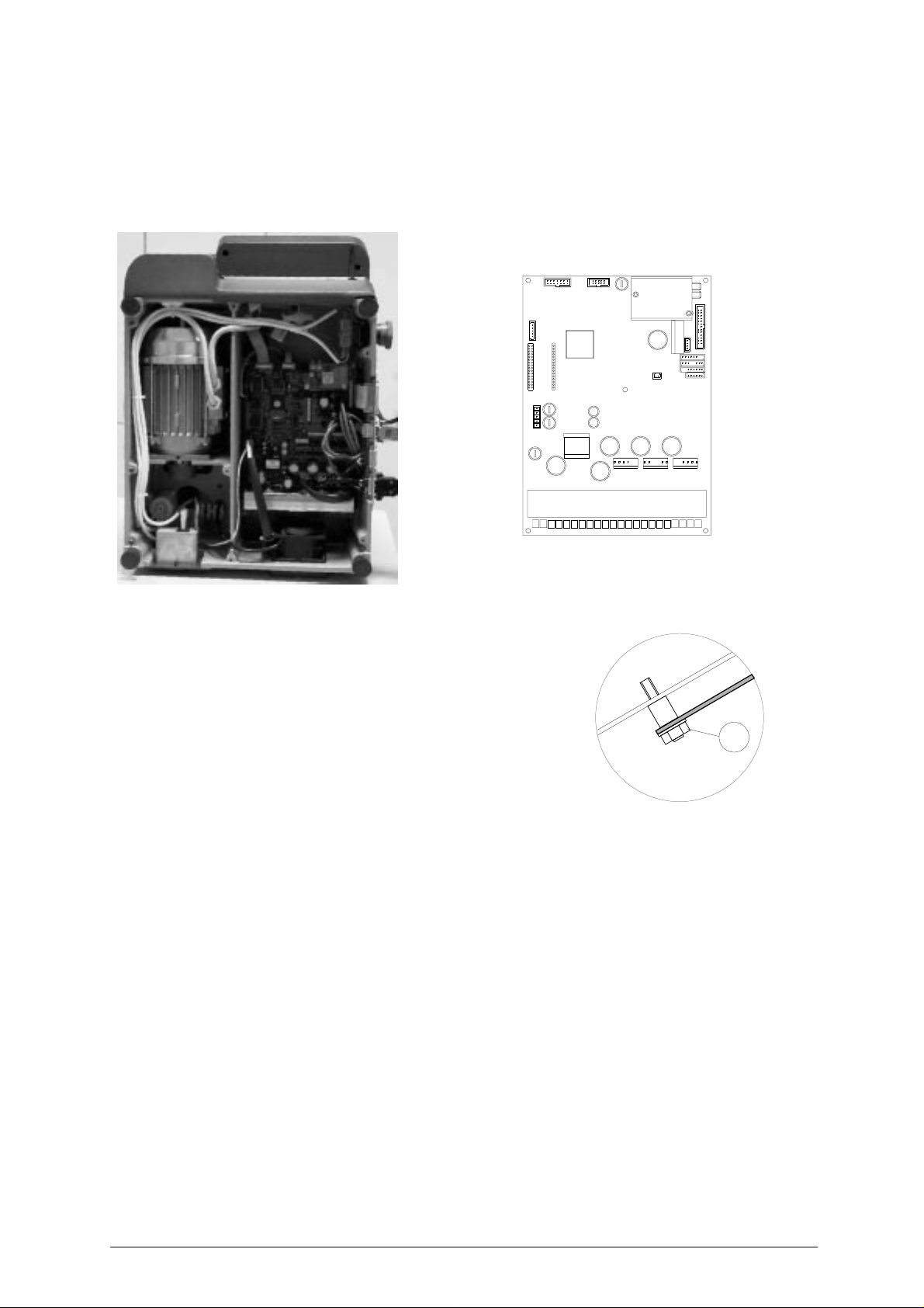
UNOCODE 299 Operating manual - English
7.6 ELECTRONIC CIRCUIT BOARD REPLACEMENT
Proceed as follows:
1) turn the machine off and unplug it from its power supply cable.
2) remove the bottom panel (ch.7.9, page 50).
3)
disconnect all cable connectors from the
electronic circuit
board
(fig. 39).
Fig. 39
4) take theelectroniccircuitboard off by unscrewing the (Y1)
nuts off (fig. 40).
5) mount the new electronic circuit board and re-connect all
cables (all cable connections are polarosed therefore
cannot be connected incorrectly).
6) re-fit the bottom panel and re-position the machine on its
workbench.
7) turn the machine on and launch the WIN-TRANSFER
program.
electronic circuit board
Y1
Fig. 40
48 Copyright Silca 2002
Page 53
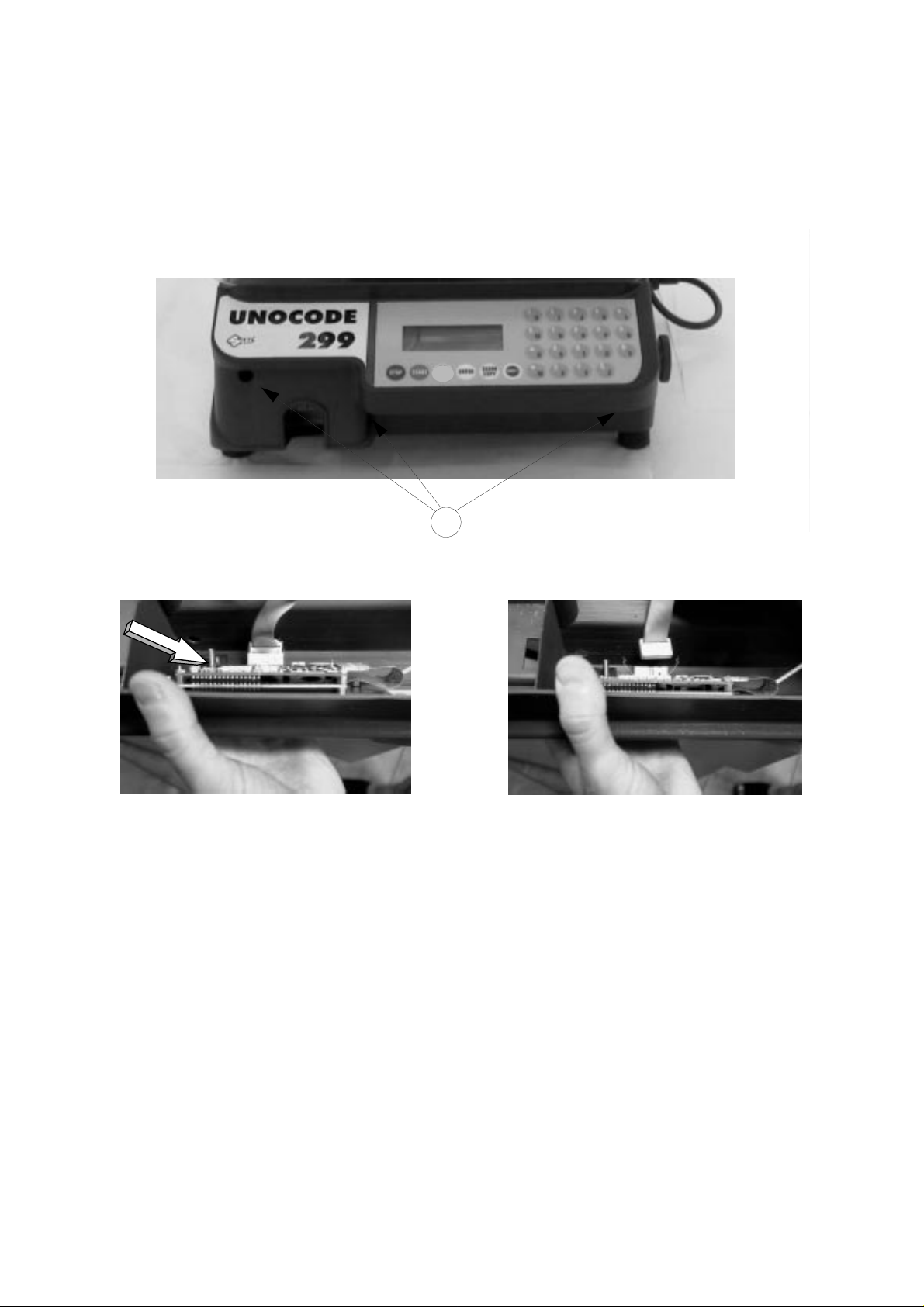
Operating manual - English UNOCODE 299
7.7 KEYBOARD/DISPLAY REPLACEMENT
1) turn the machine off and unplug it from its power supply cable.
2) remove the display’s support, by unscrewing the 3 (B1) fixing screws (fig. 41).
3) detach the flat cable and ground wire from the keyboard (fig. 42).
4) unscrew the keyboard’s fixing nuts and remove the keyboard from its support.
5) fit the new keyboard/display, repeating the operations described above, backwards.
Fig. 41
Fig. 42
B1
Copyright Silca 2002 49
Page 54
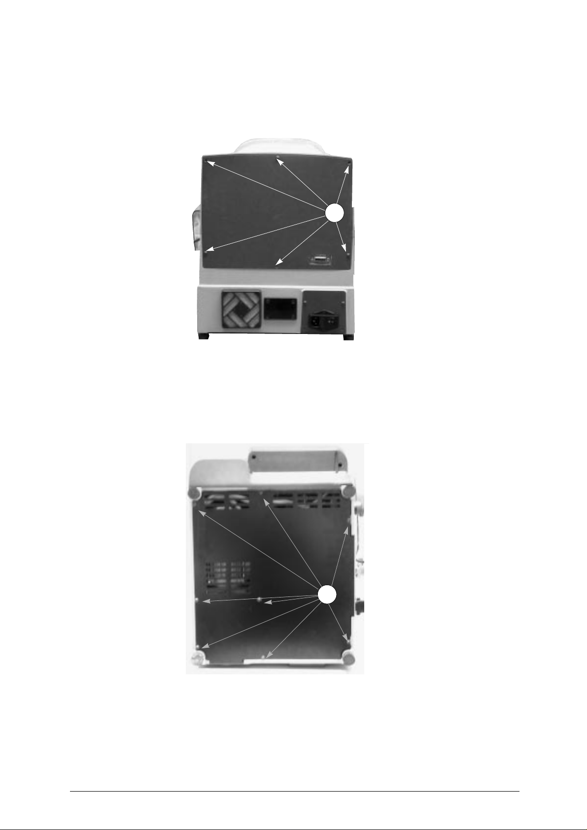
UNOCODE 299 Operating manual - English
7.8 ACCESS TO BACK COMPARTMENT
To gain access to the back compartment, proceed as follows:
1) turn the machine off and unplug it from its power supply cable.
2) unscrew the 6 (M1) screws that secure the back panel (fig. 43) thus removing it.
M1
Fig. 43
7.9 ACCESS TO BOTTOM COMPARTMENT
To gain access to the bottom compartment, proceed as follows:
1) turn the machine off and unplug it from its power supply cable.
2) turn the machine on its back side.
3) remove the machine’s bottom panel by unscrewing the 8 (L1) screws.
L1
Fig. 44
50 Copyright Silca 2002
Page 55
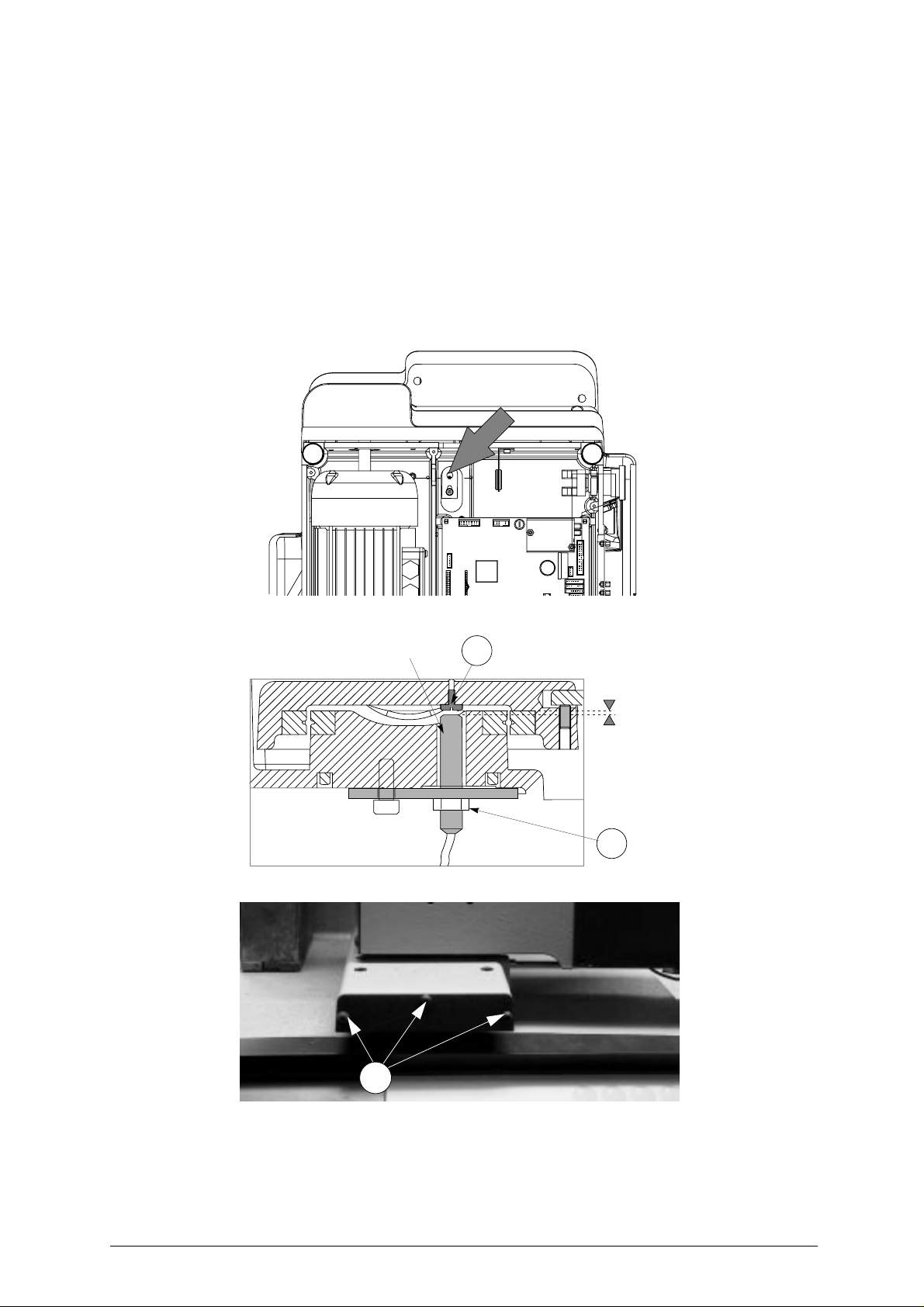
Operating manual - English UNOCODE 299
7.10 SENSOR REPLACEMENT
X
AXIS SENSOR REPLACEMENT
1) turn the machine off and unplug it from its power supply cable.
2) remove the bottom panel (chap.7.9 "Access to bottom compartment").
3) disconnect the X axis sensor’s connector from the electronic circuit board (fig. 45).
4) loosen the (L3) nut. Unscrew the sensor from the plate and remove it (fig. 46).
5) remove the front cover on the (X axis) lower carriage (fig. 47) by unscrewing the 3 (B4) screws.
6) fit the new sensor in position, tightening it until it almost touches the (L2) screw (fig. 46) thus securing
it with the (L3) nut.
7) connect the sensor’s connector to the electronic circuit board.
8) remount the bottom panel and front cover.
Fig. 45
Fig. 46
X axis sensor
L2
0,1 - 0,4 mm
L3
Fig. 47
B4
Copyright Silca 2002 51
Page 56
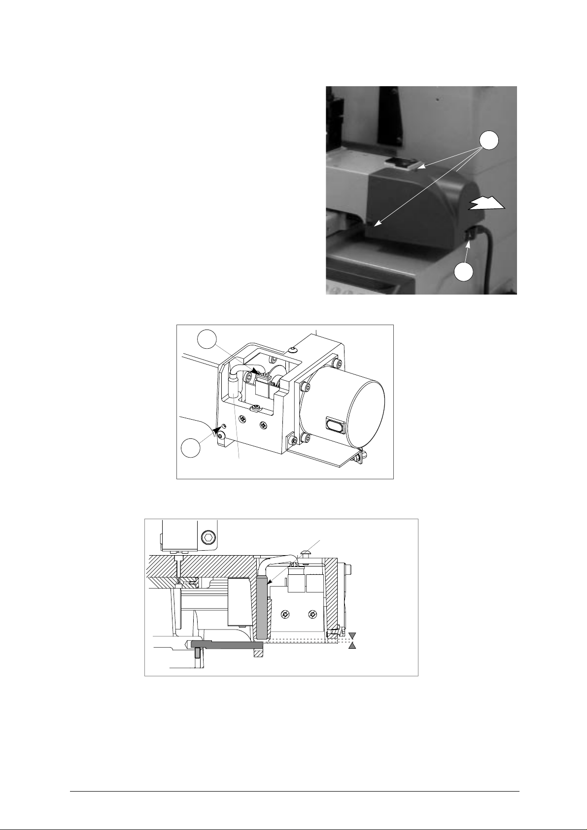
UNOCODE 299 Operating manual - English
Y
AXIS SENSOR REPLACEMENT
1) turn the machine off and unplug it from its power
supply cable.
2) raise the protective shield.
3) disconnect the (J1) Yaxis cable fromthe carriage
(fig. 48).
4) remove the Y axis carriage cover by unscrewing
the3 (B5) locking screws and pull the cover inthe
direction shown in fig. 48.
5) disconnect the (M3) sensor’s connector (fig. 49).
6) slightly loosen the (M2) grub screw with the
provided allen key.
7) remove the faulty sensor and replace it with a
new one. Screw it in until it almost touches the
underlying rod (fig. 50). Tighten the (M2) grub
screw to lock the sensor into place.
8) connect the (M3) sensor’s connector.
9) replace the Y axis carriage cover.
10) connect the (J1) Y axis connecting wire to the
carriage.
B5
J1
Fig. 48
Fig. 49
M3
M2
Y axis sensor
Y axis sensor
Fig. 50
52 Copyright Silca 2002
0,1 - 0,4 mm
Page 57
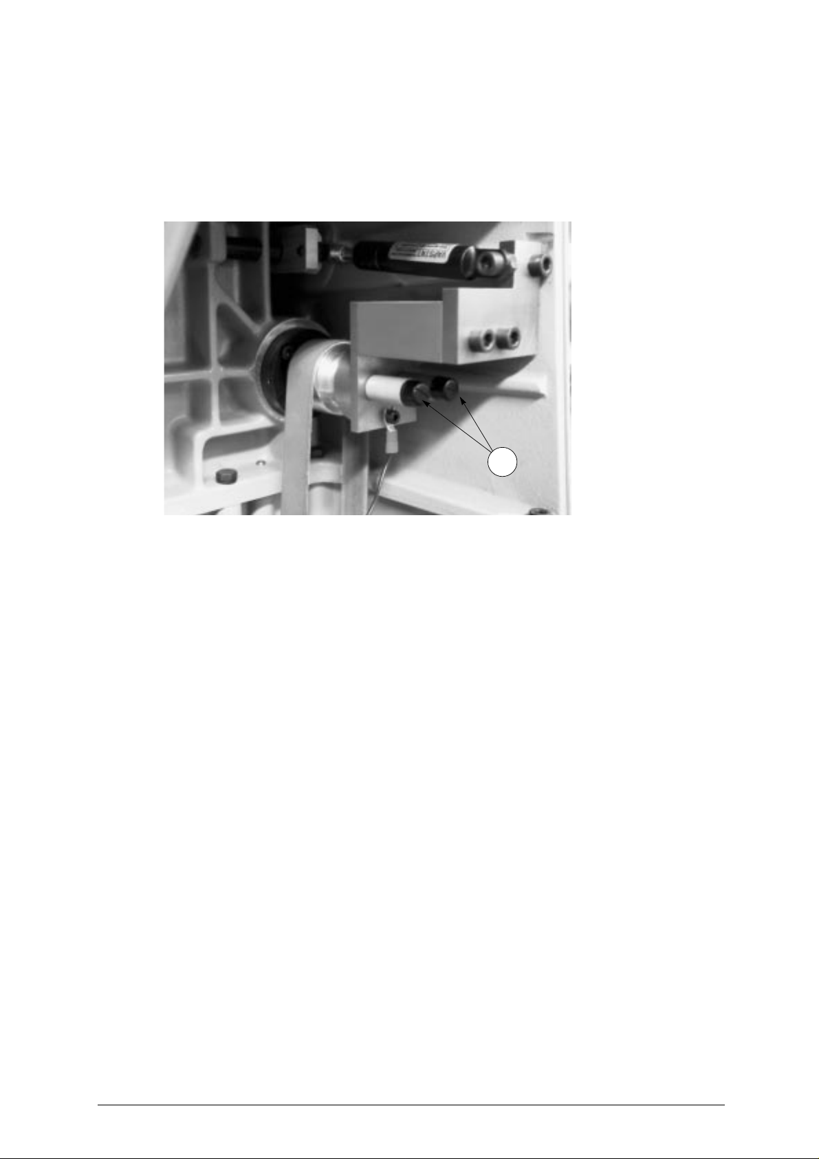
Operating manual - English UNOCODE 299
7.11 BRUSH REPLACEMENT
1) open the rear compartment (ch. 7.8, page 50).
2) unscrew the two brush caps (M4) (fig. 51), remove and fit two new brushes.
3) replace the two caps (M4).
4) close the rear compartment.
5) carry out Test 7 to check proper operation (ch. 5.6.1, page 31).
Fig. 51
M4
Copyright Silca 2002 53
Page 58

UNOCODE 299 Operating manual - English
7.12
WIN-TRANSFER PROGRAM FOR LOADING/UPDATING THE INTERNAL MACHINE
PROGRAM
The machine is supplied with an internal program already loaded and tested in our workshops. The user
therefore does not need to carry out any operations.
Only in the situations described below can the WIN-TRANSFER program be usedto re-start the machine.
The following is a list of situations where the use of the WIN-TRANSFER program is required.
For further details on installation and use of the program, follow the instructions given on the
instruction sheet provided with the disk or CD ROM.
• Replacement of the electronic board (see ch. 7.6, page 48) or loss of the internal
machine program.
1) replace the board with a new one, if necessary.
2) install onyourpersonal computer the latest version receivedofthe WinTransfer program and followthe
instructions given on the instruction sheet provided with the program.
3) read the serial number onthe data plateon the backof the machine (ch.5.8, page 40) andenter on the
machine.
4) gauge the machine according to the instructions in the manual, as follows:
- gauge as explained in chapter 5.6.2 "Machine zero points" in the user’s manual.
- gauge the V100 clamp (ch. 5.5.1, page 26).
At this point the machine is set up and ready for operation.
• At this point the machine is set up and ready for operation
1) install onyourpersonal computer the latest version receivedofthe WinTransfer program and followthe
instructions given on the instruction sheet provided with the program.
• Loading of customized key data cards provided by SILCA on Customer’s request
1) install onyourpersonal computer the latest version receivedofthe WinTransfer program and followthe
instructions given on the instruction sheet provided with the program.
54 Copyright Silca 2002
Page 59

Operating manual - English UNOCODE 299
8 DISPOSING OF MACHINE
To dispose the machine, it must be rendered unusable by carrying out the operationslisted below:
• deactivation of the electricity supply;
• separation of the plastic and metal parts;
When these operations have been carried out, the machine can be disposed of according to the current
regulations in the country of use.
WASTE DISPOSAL
CEE standards state special regulations for waste disposal (*).
Machine
The 299 UNOCODE is made up of recyclable parts.
Recycling is ecologically recommended.
Packing
The packing inwhich the machineis transported ismade of cardboardand wood therefore can be re-used
if intact or if dismantled used as combustible materials.
Warning! Take great care when dismantling the packing as it contains nails, which could cause injuries.
We recommend to bend the nails downwards into the wood with a hammer or to completely remove the
nails disposing them in authorized metal recycling centres.
The packing is considered solid urban waste and must not be thrown into the environment but placed in
special cardboard collection bins.
Waste deriving from key cutting
The waste deriving from key cutting is classified special waste, but is still classified as solid urban waste,
as metal wool.Such waste must be disposed of in special collection centres accordingto the classification
assigned to them by the current EEC law. The circumstances which transform metal residue from solid
urban waste intocontaminated or toxic noxious waste are listedin the appendicesto the current European
Union regulations regarding disposal of such waste.
To facilitate disposal of the waste generated by the machine during its operation and of the
machine itself at the end of its useful life, refer to identification of the main types of waste by the
relative European CER code:
CER code
- Electronic circuit boards 16 02 16
- Iron filings and swarf 12 01 01
- Paper and cardboard packaging 15 01 01
- Wooden packaging 15 01 03
- Plastic packaging 15 01 02
(*) Wasteisanysubstanceorobjectderiving from human activity or natural cycles, disposed off or to bedisposedoff.
Copyright Silca 2002 55
Page 60

UNOCODE 299 Operating manual - English
9 ASSISTANCE
Silca provides full service to purchasers of the UNOCODE 299 key-cutting machine. To ensure complete
safety to the operator and machine, any job not specified in this manual should only be carried out by the
manufacturer or recommended Silca Service Centres.
On the back cover of this manual is a list of the manufacturer’s addresses; listed below are the addresses
of specialized service centres.
9.1 HOW TO REQUEST SERVICE
The guarantee attached to the 299 UNOCODE ensures free repairs or replacements of faulty parts within
12 months of the date of purchase. All other service calls must be arranged by the customer with Silca or
specialized Silca service centres.
56 Copyright Silca 2002
Page 61

Operating manual - English UNOCODE 299
Appendix 1 - ELECTRICAL DIAGRAMS
The following pages contain the electrical diagrams for the UNOCODE 299 key-cutting machine
described in this manual
.
Copyright Silca 2002 Appendix - I
Page 62

Page 63
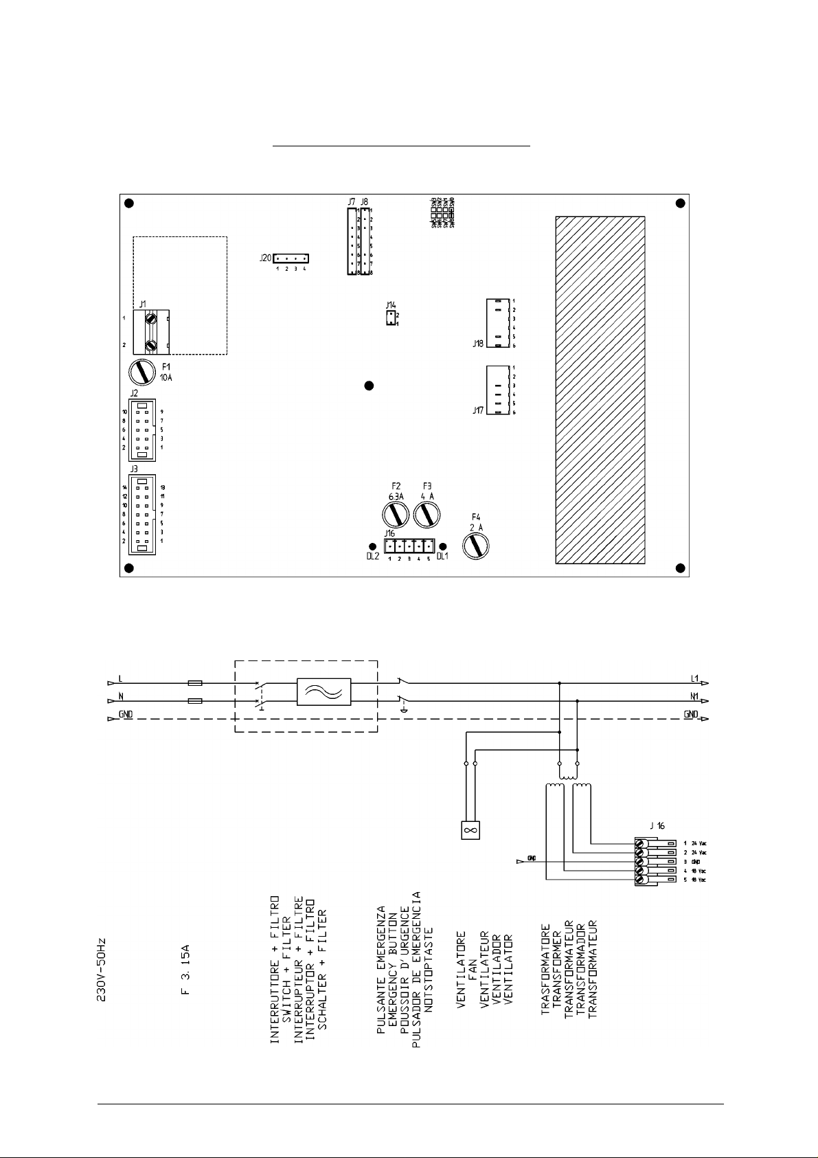
Operating manual - English UNOCODE 299
UNOCODE 299
ELECTRICAL DIAGRAMS Ver.1.0
Copyright Silca 2002 Appendix - III
Page 64
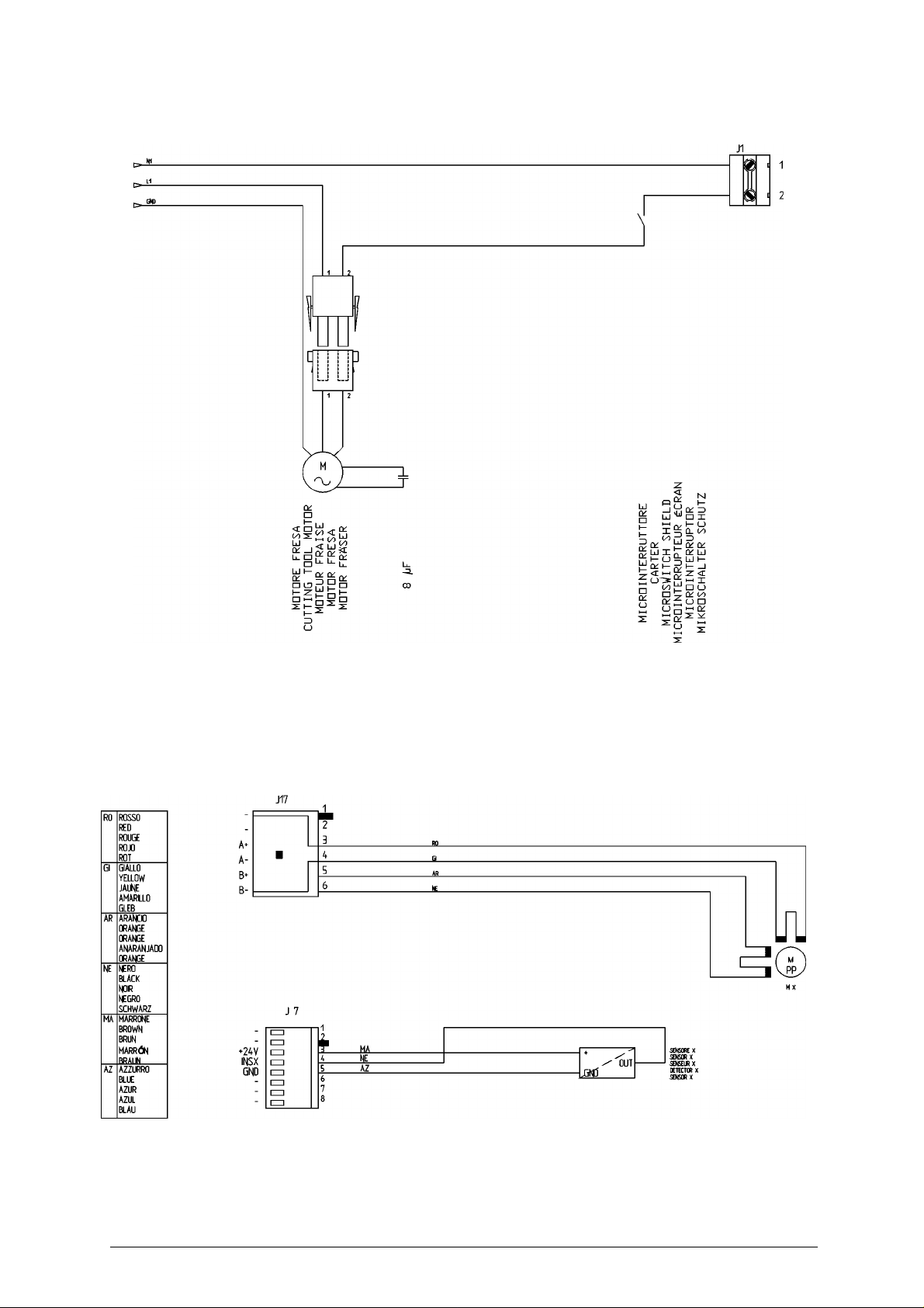
Operating manual - English UNOCODE 299
Copyright Silca 2002 Appendix - IV
Page 65
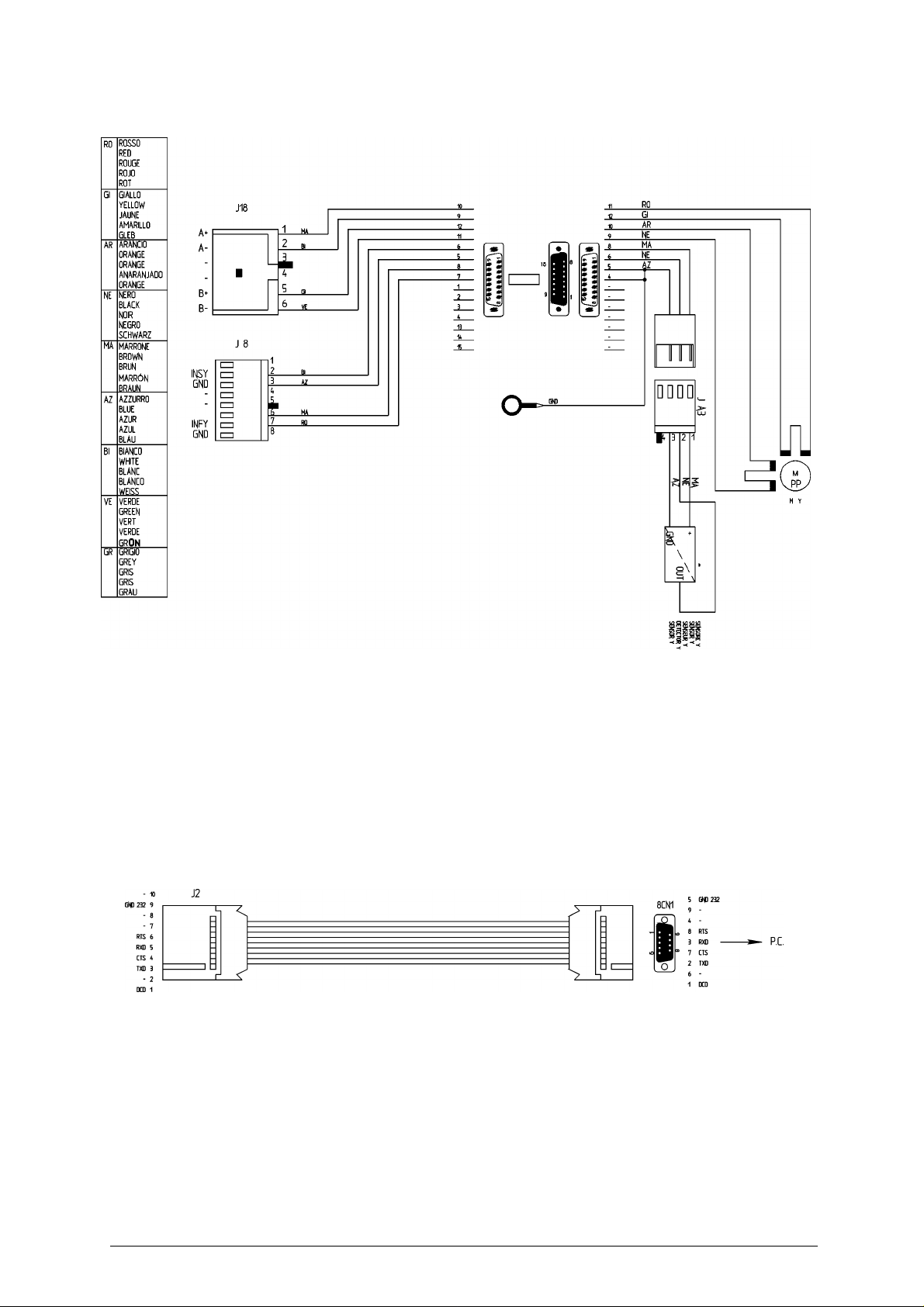
Operating manual - English UNOCODE 299
Copyright Silca 2002 Appendix - V
Page 66
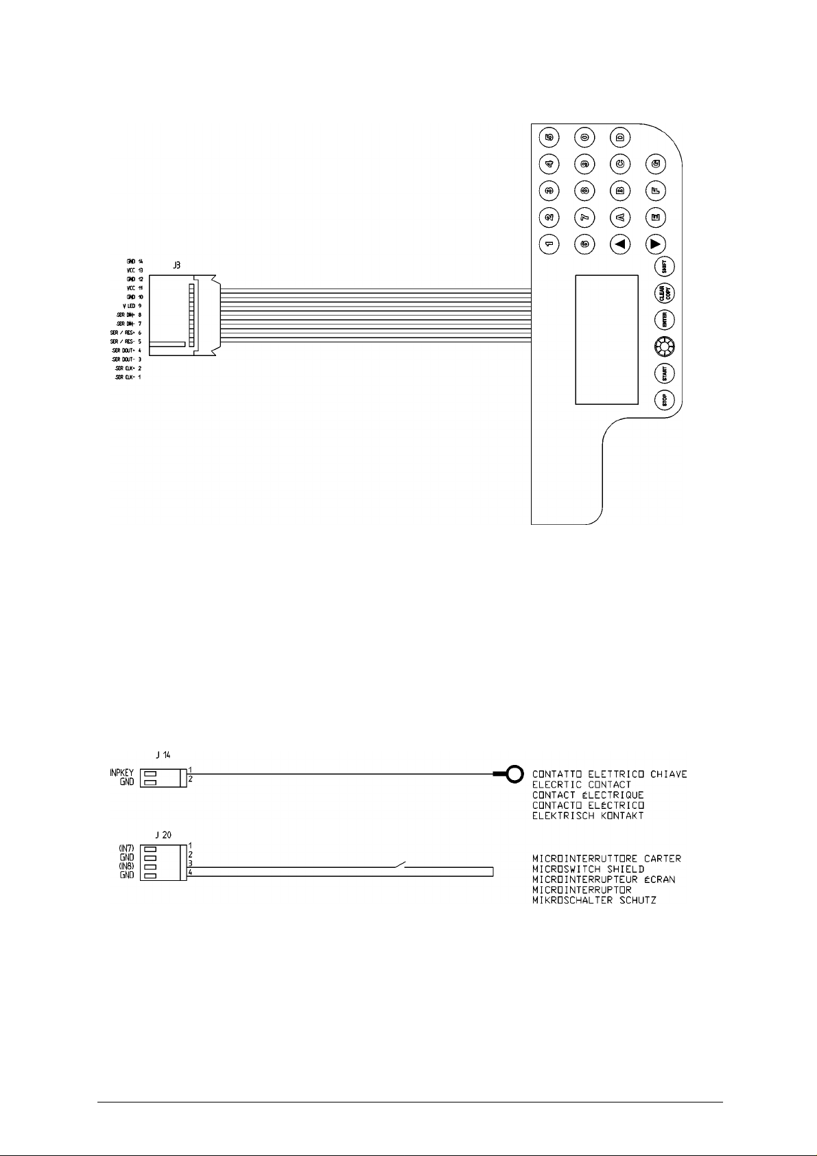
Operating manual - English UNOCODE 299
VI - Appendix Copyright Silca 2002
Page 67

SILCA S.p.A.
Via Podgora, 20 (Z.I.) 31029 VITTORIO VENETO (TV)
Tel. 0438 9136 Fax 0438 913800
www.silca.it
Member of the Kaba Group
 Loading...