

Page 1
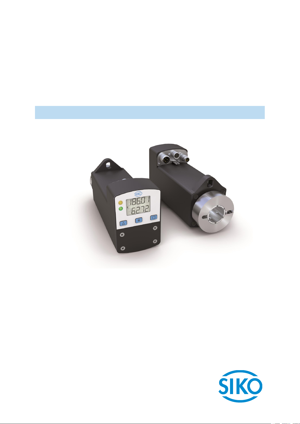
AG06
Actuator with CANopen interface
User manual
055/18
Page 2

Table of contents
1 General Information .................................................................................................. 6
1.1 Documentation ........................................................................................................6
2 Block Diagram ........................................................................................................... 6
3 Display and Control Keys ............................................................................................ 7
3.1 General ...................................................................................................................7
3.2 LCD display ..............................................................................................................7
3.3 LED displays ............................................................................................................7
4 Functional Description ............................................................................................... 8
4.1 Control of the drive ..................................................................................................8
4.1.1 Value input ..........................................................................................................8
4.1.2 Value selection .....................................................................................................8
4.1.3 Operating modes ...................................................................................................8
4.1.3.1 Positioning mode ..............................................................................................8
4.1.3.1.1 Loop positioning ............................................................................................9
4.1.3.2 Inching operation............................................................................................ 10
4.1.3.2.1 Inching mode 1 ........................................................................................... 10
4.1.3.2.2 Inching mode2 ............................................................................................ 10
4.1.3.3 Rotational speed mode ..................................................................................... 10
4.1.4 Current limiting .................................................................................................. 11
4.2 Manual control (stand-alone operation) ..................................................................... 12
4.2.1 Start inching mode 2 ........................................................................................... 12
4.2.2 Specifying the set point and starting the travel order............................................... 12
4.2.2.1 Example: Starting positioning order to position 500 ............................................. 12
4.2.2.2 Example: Starting positioning order to position -500 ............................................ 12
4.3 Menu selection ....................................................................................................... 14
4.3.1 Changeable parameters ........................................................................................ 15
4.3.1.1 Bus parameters ............................................................................................... 15
4.3.1.2 Positioning ..................................................................................................... 16
4.3.1.3 Actuator ......................................................................................................... 17
4.3.1.4 Limiting values ............................................................................................... 17
4.3.1.5 Visualization ................................................................................................... 18
4.3.1.6 Options .......................................................................................................... 19
4.3.1.7 Controller parameters ....................................................................................... 21
4.3.2 Readable parameters ........................................................................................... 21
4.3.3 Error memory ...................................................................................................... 22
5 Calibration .............................................................................................................. 22
6 External gear ........................................................................................................... 23
7 Warnings / Errors ..................................................................................................... 23
7.1 Warnings ............................................................................................................... 23
AG06
Date: 07.02.2018 Art. No. 85674 Mod. status 055/18 Page 2 of 114
Page 3

7.2 Errors .................................................................................................................... 24
7.2.1 Error codes ......................................................................................................... 24
7.3 Input errors ........................................................................................................... 25
8 Parameter description .............................................................................................. 25
9 Communication via CAN bus ..................................................................................... 33
9.1 General remarks ...................................................................................................... 33
9.1.1 Interface ........................................................................................................... 33
9.2 System Status Word ................................................................................................ 34
9.2.1 Meaning of the bits ............................................................................................. 34
9.3 CANopen protocol ................................................................................................... 36
9.3.1 Telegram setup ................................................................................................... 36
9.3.2 Network management (NMT) ................................................................................. 37
9.3.2.1 State Diagramm ............................................................................................... 37
9.3.2.2 NMT Status 'INITIALISATION' ............................................................................. 37
9.3.2.3 NMT Status 'PRE-OPERATIONAL' .......................................................................... 37
9.3.2.4 NMT Status 'OPERATIONAL' ................................................................................ 38
9.3.2.5 NMT Status 'STOPPED' ....................................................................................... 38
9.3.2.6 Switching between communication states ........................................................... 38
9.3.3 SYNC-Objekt ....................................................................................................... 38
9.3.4 Process Data Objects (PDOs) ................................................................................. 39
9.3.5 Transmit-PDOs .................................................................................................... 39
9.3.5.1 1st Transmit PDO (TPDO1) .................................................................................. 39
9.3.5.2 3rd Transmit PDO (TPDO3).................................................................................. 39
9.3.5.3 4th Transmit PDO (TPDO4) ................................................................................. 40
9.3.5.4 Transfer types of the Transmit PDOs ................................................................... 40
9.3.6 Receive-PDOs...................................................................................................... 41
9.3.6.1 1st Receive PDO (RPDO1) ................................................................................... 41
9.3.6.2 3rd Receive PDO (RPDO3) ................................................................................... 41
9.3.6.3 4th Receive PDO (RPDO4) ................................................................................... 42
9.3.6.4 Transfer types of the Receive PDOs ..................................................................... 42
9.3.7 Service Data Objects (SDOs) .................................................................................. 43
9.3.7.1 Error code ...................................................................................................... 44
9.3.8 Example: Parameterization ................................................................................... 44
9.3.8.1 Example: Read parameter .................................................................................. 44
9.3.8.2 Example: Write parameter ................................................................................. 45
9.3.9 Emergency Object (EMCY) ..................................................................................... 46
9.3.9.1 Error Code ...................................................................................................... 46
9.3.10 Heartbeat protocol .............................................................................................. 48
9.3.11 Node Guarding .................................................................................................... 49
9.4 State Machine ........................................................................................................ 50
9.5 Status word ........................................................................................................... 52
9.6 Control word .......................................................................................................... 54
9.7 Flowchart of the Profile Position Mode (positioning mode) ........................................... 56
AG06
Date: 07.02.2018 Art. No. 85674 Mod. status 055/18 Page 3 of 114
Page 4

9.8 Flowchart of the Profile Velocity Mode operation mode (velocity mode) ......................... 57
9.9 Examples ............................................................................................................... 58
9.9.1 Example of the Profile Position Mode (positioning mode) ......................................... 58
9.9.2 Example of the Profile Velocity Mode (velocity mode)............................................... 58
9.10 Overview of CANopen identifiers ............................................................................... 59
9.11 Setting the CAN baud rate ....................................................................................... 59
9.12 EDS file ................................................................................................................. 60
9.13 Directory of objects ................................................................................................ 60
9.13.1 Overview of objects ............................................................................................. 60
9.13.2 Description of objects .......................................................................................... 63
9.13.2.1 1000h: Device Type .......................................................................................... 63
9.13.2.2 1001h: Error Register ........................................................................................ 64
9.13.2.3 1002h: Manufacturer Status Register ................................................................... 64
9.13.2.4 1003h: Pre-defined Error Field ............................................................................ 65
9.13.2.5 1005h: COB-ID Sync Message ............................................................................. 65
9.13.2.6 1008h: Manufacturer Device Name ...................................................................... 66
9.13.2.7 100Ah: Manufacturer Software Version ................................................................ 66
9.13.2.8 100Ch: Guard Time ........................................................................................... 67
9.13.2.9 100Dh: Life Time Factor .................................................................................... 67
9.13.2.10 1011h: Restore Default Parameters ..................................................................... 67
9.13.2.11 1014h: COB-ID Emergency Message ..................................................................... 69
9.13.2.12 1017h: Producer Heartbeat Time ......................................................................... 70
9.13.2.13 1018h: Identity Object ...................................................................................... 70
9.13.2.14 1200h: Server SDO Parameter ............................................................................. 72
9.13.2.15 1400h: 1st Receive PDO Parameter ....................................................................... 73
9.13.2.16 1401h: 2nd Receive PDO Parameter ...................................................................... 75
9.13.2.17 1402h: 3rd Receive PDO Parameter ....................................................................... 76
9.13.2.18 1403h: 4th Receive PDO Parameter ...................................................................... 78
9.13.2.19 1600h: 1st Receive PDO Mapping Parameter .......................................................... 80
9.13.2.20 1601h: 2nd Receive PDO Mapping Parameter ......................................................... 80
9.13.2.21 1602h: 3rd Receive PDO Mapping Parameter .......................................................... 81
9.13.2.22 1603h: 4th Receive PDO Mapping Parameter .......................................................... 82
9.13.2.23 1800h: 1st Transmit PDO Parameter ..................................................................... 83
9.13.2.24 1801h: 2nd Transmit PDO Parameter ..................................................................... 85
9.13.2.25 1802h: 3rd Transmit PDO Parameter ..................................................................... 86
9.13.2.26 1803h: 4th Transmit PDO Parameter ..................................................................... 88
9.13.2.27 1A00h: 1st Transmit PDO Mapping Parameter ........................................................ 91
9.13.2.28 1A01h: 2nd Transmit PDO Mapping Parameter ........................................................ 91
9.13.2.29 1A02h: 3rd Transmit PDO Mapping Parameter ........................................................ 92
9.13.2.30 1A03h: 4th Transmit PDO Mapping Parameter ........................................................ 93
9.13.2.31 2001h: Manufacturer Offset ............................................................................... 94
9.13.2.32 2100h: CAN baud rate ....................................................................................... 94
9.13.2.33 2101h: Node-ID ............................................................................................... 95
9.13.2.34 2102h: Gear reduction ...................................................................................... 95
AG06
Date: 07.02.2018 Art. No. 85674 Mod. status 055/18 Page 4 of 114
Page 5

9.13.2.35 2400h: Display and Operation Parameter Set ........................................................ 95
9.13.2.36 2410h: Motor Parameter Set .............................................................................. 99
9.13.2.37 2412h: Spindle Pitch ...................................................................................... 102
9.13.2.38 2413h: Pos Type............................................................................................. 102
9.13.2.39 2415h: Delta Jog............................................................................................ 103
9.13.2.40 2416h: Stop Mode Inching Mode 2 .................................................................... 103
9.13.2.41 2417h: Inpos Mode ......................................................................................... 103
9.13.2.42 2418h: Loop Length ....................................................................................... 104
9.13.2.43 2419h: Contouring Error Limit .......................................................................... 104
9.13.2.44 241Ah: Contouring Error .................................................................................. 104
9.13.2.45 241Bh: Power Supply Voltage ........................................................................... 105
9.13.2.46 241Ch: Output Stage Temperature ..................................................................... 105
9.13.2.47 241Eh: Motor Current ...................................................................................... 106
9.13.2.48 2421h: Motor Current Limit .............................................................................. 106
9.13.2.49 2423h: Battery Voltage ................................................................................... 106
9.13.2.50 2450h: Inching 2 Offset .................................................................................. 107
9.13.2.51 2451h: Type of acceleration Inching mode 2 ...................................................... 107
9.13.2.52 2500h: Production Date .................................................................................. 107
9.13.2.53 2501h: Display Software Version ....................................................................... 108
9.13.2.54 6040h: Control word ....................................................................................... 108
9.13.2.55 6041h: Status word ........................................................................................ 109
9.13.2.56 6060h: Modes of Operation .............................................................................. 109
9.13.2.57 6061h: Modes of Operation Display ................................................................... 110
9.13.2.58 6064h: Position Actual Value ........................................................................... 110
9.13.2.59 6067h: Position Window .................................................................................. 111
9.13.2.60 606Ch: Velocity Actual Value ............................................................................ 111
9.13.2.61 607Ah: Target Position ................................................................................... 111
9.13.2.62 607Ch: Calibration Value ................................................................................. 112
9.13.2.63 607Dh: Software Position Limit ........................................................................ 112
9.13.2.64 607Eh: Polarity .............................................................................................. 113
9.13.2.65 6091h: Gear Ratio .......................................................................................... 113
9.13.2.66 60FFh: Target Velocity .................................................................................... 114
AG06
Date: 07.02.2018 Art. No. 85674 Mod. status 055/18 Page 5 of 114
Page 6
General Information
Inverse-
protection
Motor
+UB
control
CAN
+UB
stage
Inverse-
protection
1 General Information
This user manual is valid with firmware version PC 2.04 or higher!
1.1 Documentation
The following documents are associated with this document:
The data sheet describes the technical data, the dimensions, the pin assignment, the
accessories and the order key.
The installation instructions describe the mechanical and electrical installation with all
safety-relevant conditions and the associated technical specifications.
The User manual for actuator commissioning and integration into a fieldbus system.
You can also download these documents at http://www.siko-global.com/p/ag06.
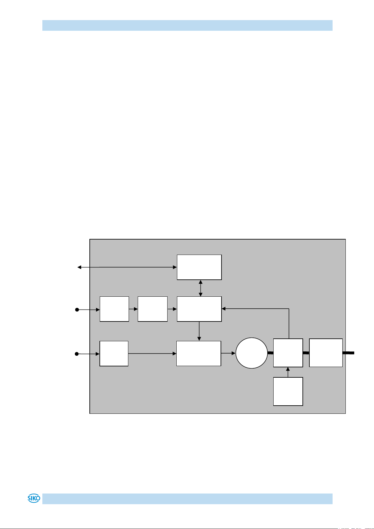
2 Block Diagram
polarity
output
polarity
Mains
adapter
Verpolschutz
Bus electronics
Control
Output stage
Encoder
Battery
Gear
Fig. 1: Block diagram
AG06
Date: 07.02.2018 Art. No. 85674 Mod. status 055/18 Page 6 of 114
Page 7
Display and Control Keys
LED
Colour
State
Description
LED1
green
on
Actuator is within the programmed position window.
Supply voltage of the output stage is applied.
blinking
Actuator is within the programmed position window.
Supply voltage of the output stage is missing.
off
Actuator is outside the programmed position window.
red
on
Actuator is outside the programmed position window.
Supply voltage of the output stage is applied.
blinking
Actuator is outside the programmed position window.
Supply voltage of the output stage is missing.
off
Actuator is within the programmed position window.
LED2
orange
blinking 2.5 Hz
NMT state: 'PRE-OPERATIONAL'
on
NMT state: 'OPERATIONAL'
blinking pulseduty factor 1:5
off
NMT state: 'STOPPED'
LED2
LED1
LCD display
Keys
3 Display and Control Keys
3.1 General
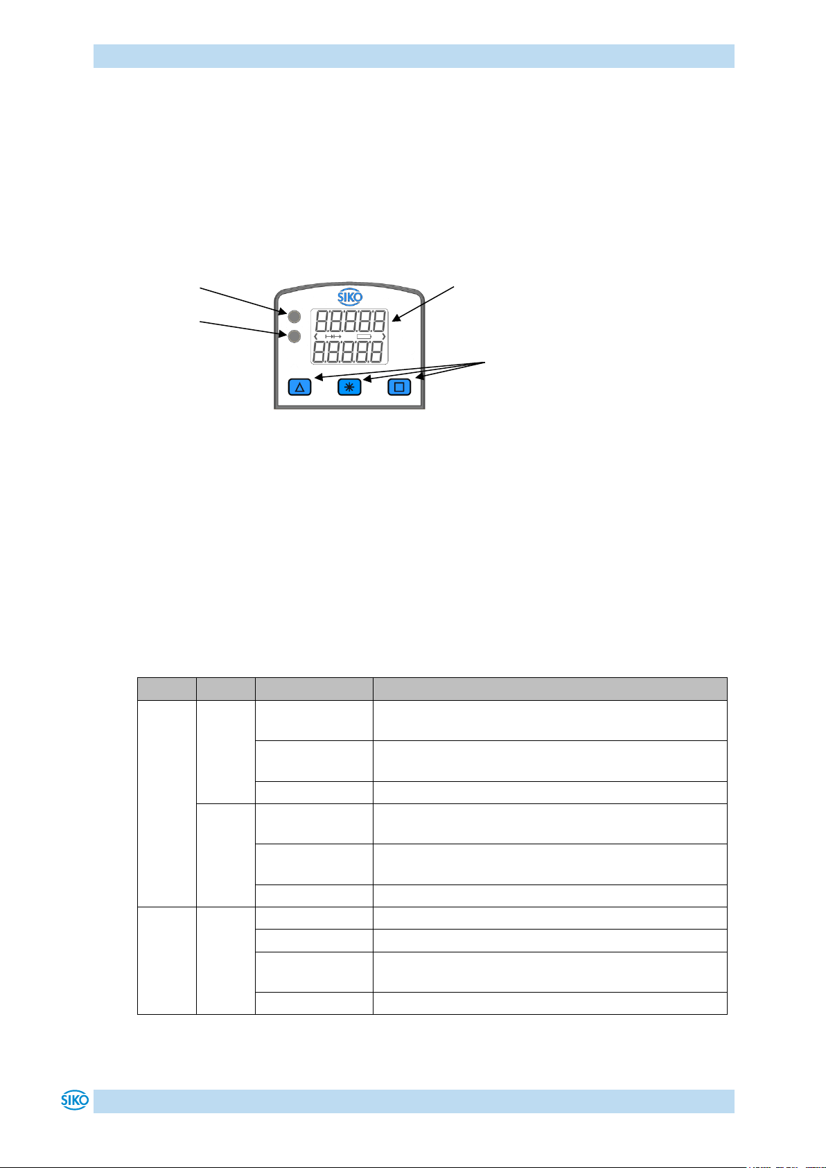
The actuator has a two-line display with special characters and three control keys. The keys
serve for actuator parameterization and control. Two LEDs (1, 2) inform about the actuator's
operating state.
Fig. 2: Control elements
3.2 LCD display
With supply voltage applied to the control, the actual value is displayed in the first line and
the set point value with factory settings in the second line.
The value displayed in the 2nd line can be adjusted via parameters.
3.3 LED displays
Table 1: LED displays
AG06
Date: 07.02.2018 Art. No. 85674 Mod. status 055/18 Page 7 of 114
Page 8
Functional Description
With value input via the keys, the display range is limited to -19999 …
99999. When entering values beyond this range via CAN interface, ""
will be displayed when you select the parameter.
4 Functional Description
4.1 Control of the drive
The drive can be controlled manually (stand-alone) and completely parameterized via the
keys. In bus operation you can disable drive control via the keys.
4.1.1 Value input
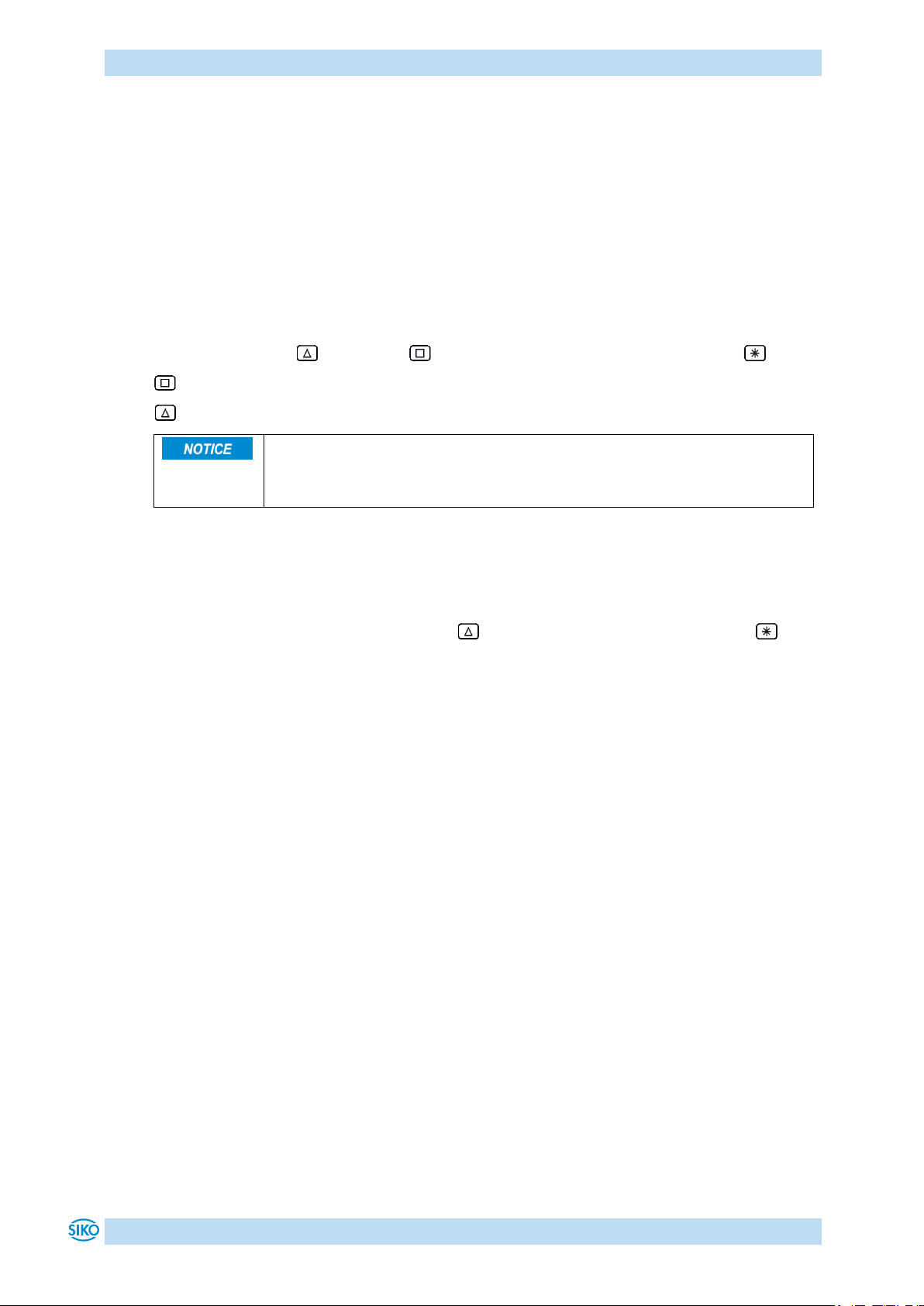
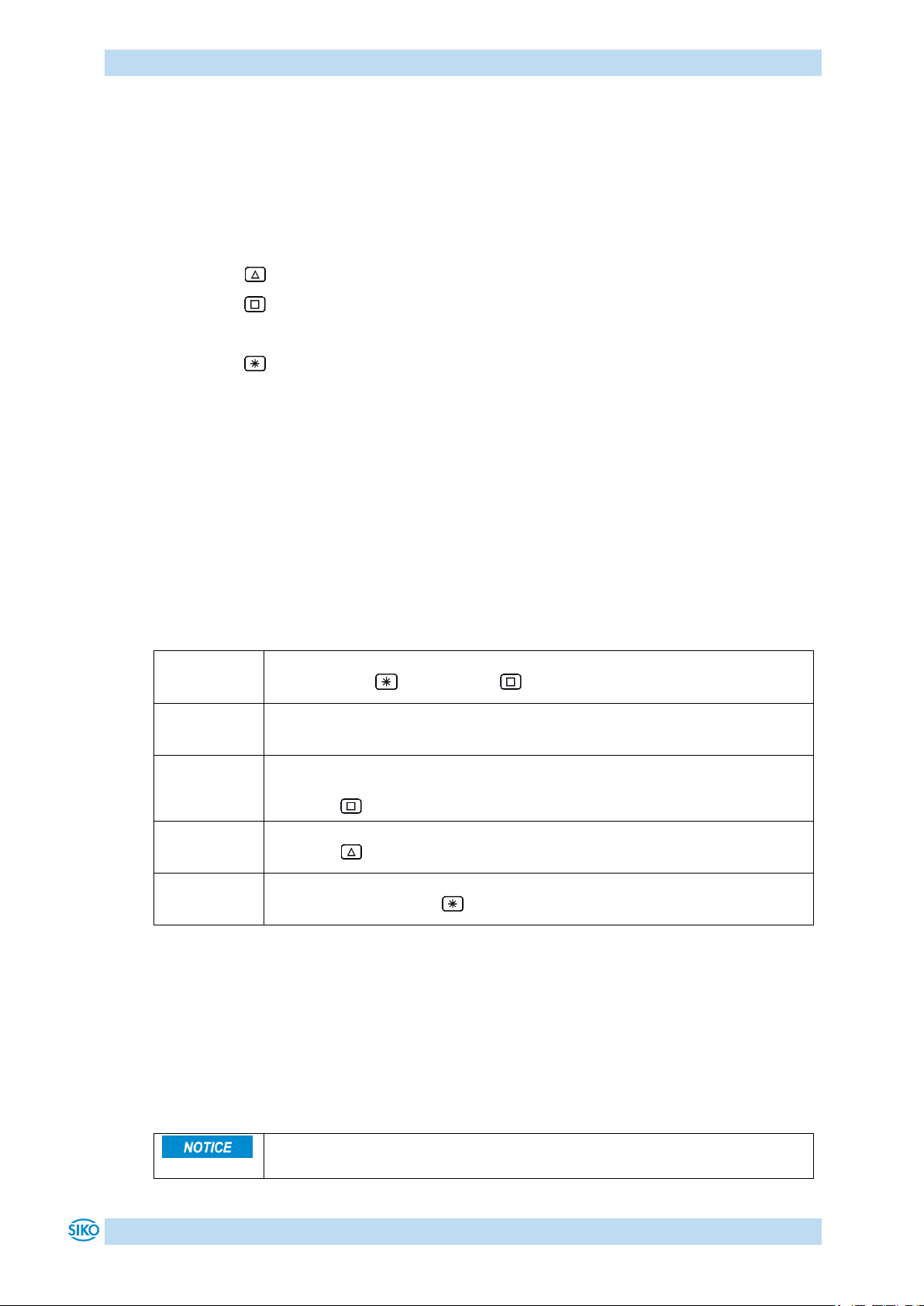
Enter values via the key and the key. Confirm entered values by pressing the key.
- Decimal place selection key
- Value input key
4.1.2 Value selection
For some parameters you can select values from a list. Direct value input is not possible.
You can select a value from the list via the key. Confirm the value by pressing the key.
4.1.3 Operating modes
The following operating modes are distinguished: positioning mode and speed mode. In the
positioning mode there is the additional option of travelling in the inching mode.
4.1.3.1 Positioning mode
In the positioning mode, positioning to the specified set point is executed by means of a
ramp function (see Fig. 3), calculated on the basis of the actual position as well as the
programmed controller parameters P (proportional factor), I (integral factor), D (differential
factor), acceleration and speed.
Upon activation of the travel order, the actuator accelerates to the specified speed with the
acceleration programmed. The value of deceleration to the set point is defined by the
parameter 'a-Pos' as well.
If the actual position is within the programmed window, this will be signalled by LED1, in the
system status word and in the CAN status word. You can define the behaviour of the actuator
upon reaching the programmed window.
Changing controller parameters during a positioning process does not influence the current
positioning operation.
AG06
Date: 07.02.2018 Art. No. 85674 Mod. status 055/18 Page 8 of 114
Page 9
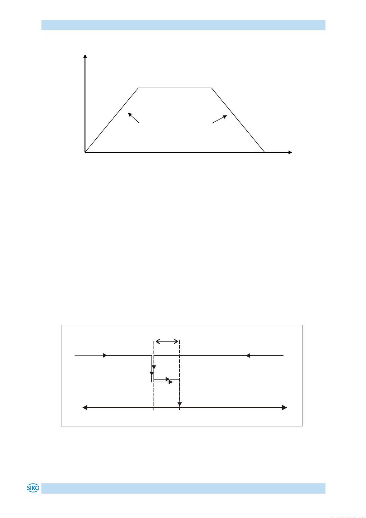
Functional Description
Start position
Target position
Time
Speed
Speed
Acceleration = deceleration
(Parameter no. 4)
Positioning: loop +
Set point
Positioning in positive
direction
Positioning in negative
direction
Loop length
-
+
Fig. 3: Ramp travel, direct positioning mode
(Parameter no. 5)
4.1.3.1.1 Loop positioning
If the actuator is operated on a spindle or an additional gear, the spindle or external gear
backlash can be compensated by means of loop positioning. In this case, travelling to the
target value is always from the same direction. This direction of approach can be defined.
Example:
The direction from which every target position shall be driven to is positive.
Case 1 new position is greater than actual position:
Direct travel to the target position
Case 2 new position is smaller than actual position:
The actuator drives beyond the target position by the loop length; afterwards, the set
point is approached in positive direction.
Fig. 4: Positioning Loop+
AG06
Date: 07.02.2018 Art. No. 85674 Mod. status 055/18 Page 9 of 114
Page 10
Functional Description
There is no compensation for spindle play (loop positioning) in this
operating mode.
If the 'Spindle pitch' parameter is programmed to zero, then the travelling
way occurs by increments. If 'Spindle pitch' is unequal zero, then the
information of the 'Delta Tipp' parameter refers to the travel distance in
1/100 mm.
If the actual position is outside the programmed limiting values, then
travelling from this position in the respective direction is possible by means
of inching mode 1 or 2!
4.1.3.2 Inching operation
Inching operation is enabled in the 'positioning mode' only. You can program via parameters
acceleration as well as speed in the inching mode.
4.1.3.2.1 Inching mode 1
The drive travels once from the current actual position by the position 'Delta Tipp' depending
on the mathematical sign of the value entered.
'Delta Tipp' <0: negative travel direction
'Delta Tipp' >0: positive travel direction
Reaching of the target position will be signalled accordingly.
The following conditions must be met for enabling the start of inching modes 1 and 2:
The actuator must not be switched to error
No active travel job
Supply voltage of the output stage is applied
4.1.3.2.2 Inching mode2
The actuator travels from the current position as long as the relevant command is active. You
can influence the inching speed via two parameters and it will be calculated in the actuator
as illustrated in the example below:
v - Tipp (Parameter no. 9) = 10 rpm (can only be changed in the idle state)
Offset inching 2 (Parameter no. 30) = 85 % (can be changed during inching operation)
The resulting inching speed in this example will be:
Inching speed = v - Tipp * Offset inching 2 = 10 rpm * 85 % = 9 rpm
The results are always rounded to integers. The minimum speed is 1 rpm.
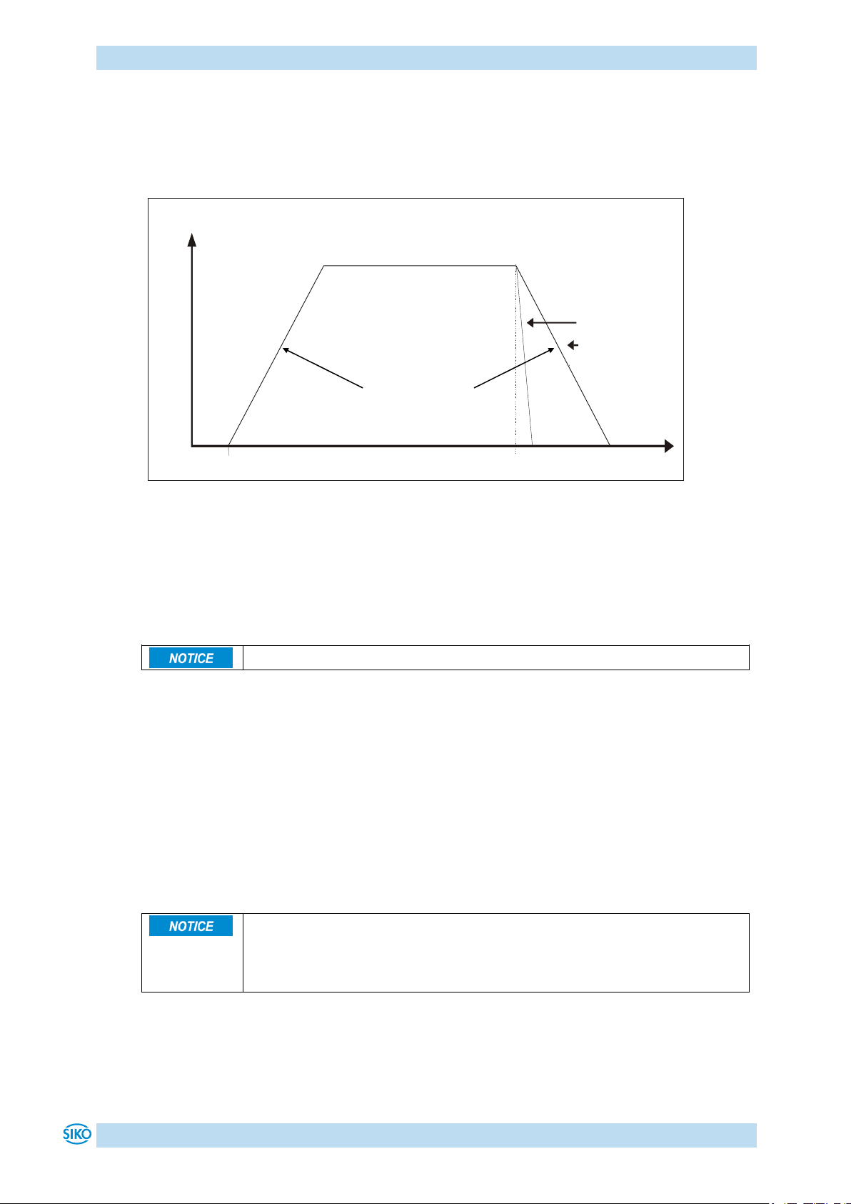
4.1.3.3 Rotational speed mode
With the set point enabled, the actuator when in the rotational speed mode accelerates to the
target speed and maintains this speed until the set point is disabled or a different target
speed specified.
AG06
Date: 07.02.2018 Art. No. 85674 Mod. status 055/18 Page 10 of 114
Page 11
Functional Description
Limits 1 + 2 are inactivated in this operational mode.
The actual motor current cannot be stated by measuring the supply current.
With cycled output stages, the supply current does not correspond to the
motor current. The actual motor current can be read out via the interface or
indicated on the display.
Speed
Time
Target speed
(set point)
Acceleration
Parameter no. 8
'Stop'
Set point enabled
Disable set point
or set point = 0
Disable operation
The speed is adjusted immediately to the new value when the rotational target speed is
changed.
The arithmetical sign of the set point determines the travel direction in the rotational speed
mode.
Fig. 5: Ramp rotational speed mode
The following conditions must be met for enabling the start of the rotational speed mode:
The actuator must not be switched to error
No active travel job
Supply voltage of the output stage is applied
4.1.4 Current limiting
The actuator is equipped with adjustable current limiting, which serves primarily for
protecting the actuator against overload.
With the default value set, the nominal speed indicated on the data sheet is achieved.
Actuator overload results in limiting the motor current to the set value.
As a consequence, the actuator cannot maintain the speed set, the contouring error increases.
With the contouring error exceeding the contouring error limit the actuator will enter the
state of error: contouring error.
AG06
Date: 07.02.2018 Art. No. 85674 Mod. status 055/18 Page 11 of 114
Page 12
Functional Description
Initial state: normal display
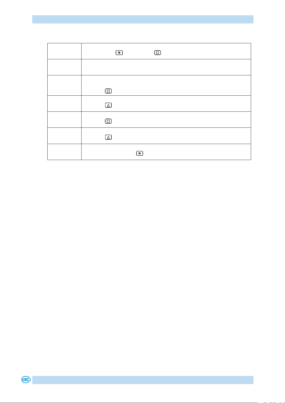
First press the key, then the key and hold down together.
The key enable time is counted down.
After expiry of the key enable time, the input field is released.
The first decimal place is active.
Press the key twice to change the active decimal place.
The third decimal place is active.
Press the key 5 times.
Value 500 will be displayed.
Confirm by pressing the key to start positioning.
For negative values to be entered, set first the value and only afterwards
the arithmetical sign. The value 0 cannot be entered.
4.2 Manual control (stand-alone operation)
4.2.1 Start inching mode 2
After applying supply voltage, the actuator will be on the uppermost level of the menu
structure (default/delivery state). Positioning mode is active.
Pressing the key starts left-hand motion (inching operation 2).
Pressing the key starts right-hand motion (inching operation 2).
Releasing the respective key stops travel movement.
Pressing the key starts the parameterization/programming mode.
4.2.2 Specifying the set point and starting the travel order
4.2.2.1 Example: Starting positioning order to position 500
Preconditions:
The display is at the uppermost level of the menu structure (basic state).
Operating mode: Positioning mode
Key functions: enabled
4.2.2.2 Example: Starting positioning order to position -500
Preconditions:
The display is at the uppermost level of the menu structure (basic state).
Operating mode: Positioning mode
Key functions: enabled
AG06
Date: 07.02.2018 Art. No. 85674 Mod. status 055/18 Page 12 of 114
Page 13
Functional Description
Initial state: normal display
First press the key, then the key and hold down together.
The key enable time is counted down.
After expiry of the key enable time, the input field is released
The first decimal place is active and blinks.
Press the key twice to change the active decimal place.
The third decimal place is active and blinks.
Press the key 5 times for entering the value.
Value 500 will be displayed.
Press the key twice to change the active decimal place.
The fifth decimal place is active and blinks.
Press the key 11 times for setting the arithmetical sign.
Value -500 will be displayed.
Confirm by pressing the key to start positioning.
AG06
Date: 07.02.2018 Art. No. 85674 Mod. status 055/18 Page 13 of 114
Page 14
Functional Description
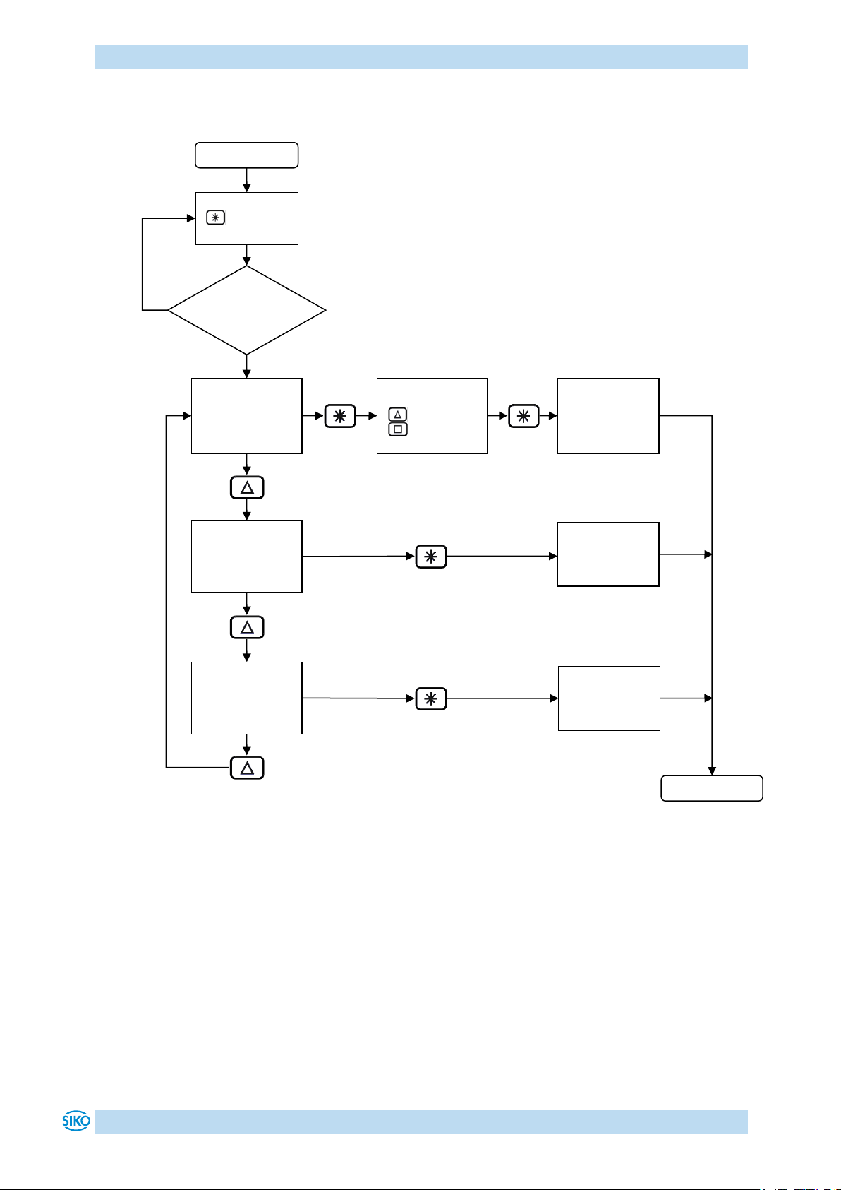
Start
Hold down the
Changeable
Only readable
Error memory
PIN – input
see menu
parameters
see menu
Key enable
expired?
see menu
End
yes
no
4.3 Menu selection
key
time
parameters
required
key
key
changeable
parameters
parameters
Fig. 6: Menu selection
only readable
error memory
AG06
Date: 07.02.2018 Art. No. 85674 Mod. status 055/18 Page 14 of 114
Page 15
Functional Description
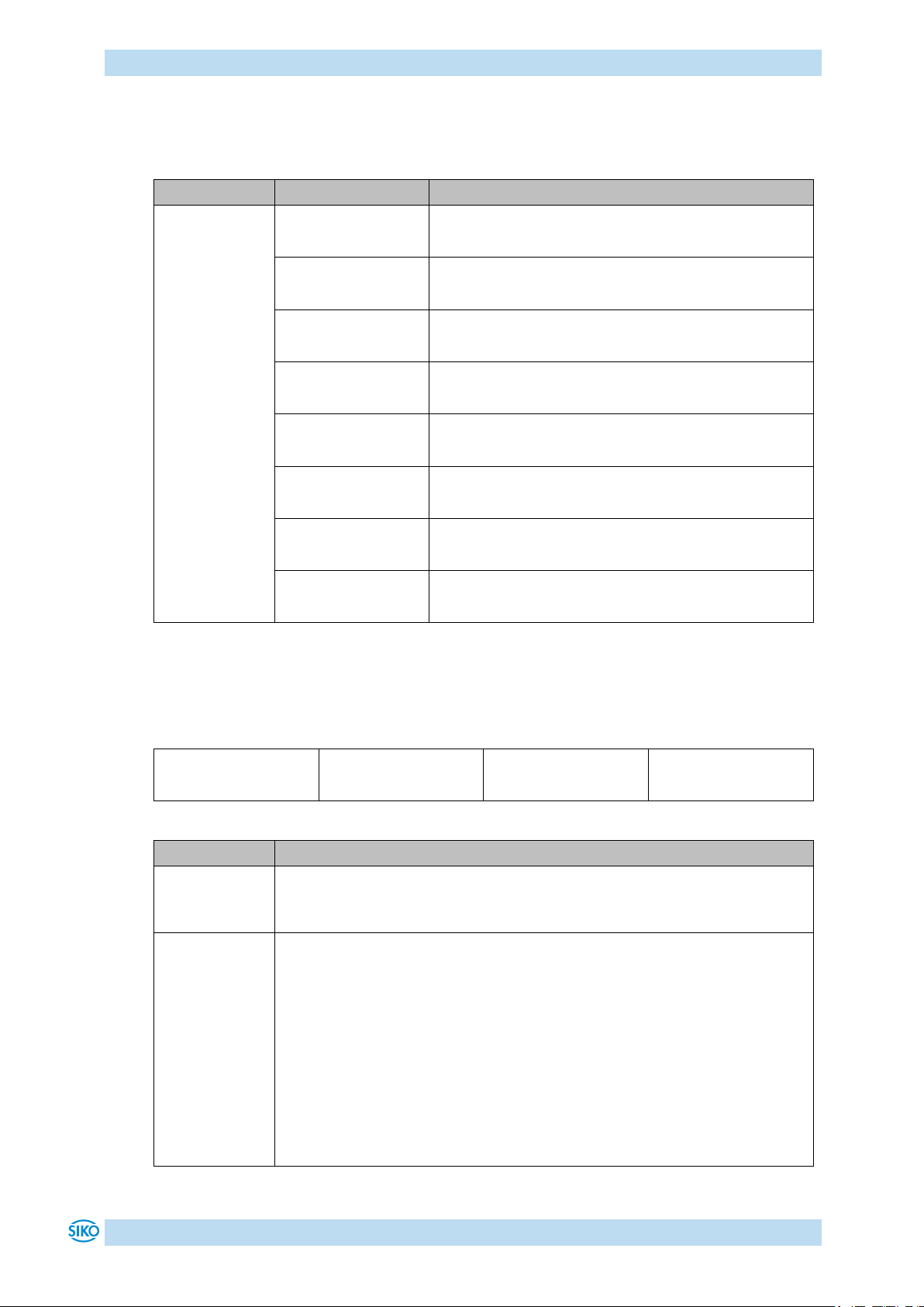
Menu
Sub-menu
Description
Bus parameters
Positioning
Actuator
Limiting values
Visualization
Options
Controller parameter
Exit menu
Menu
Sub-menu
Parameter
Description
Node address
Value range: 1 - 127
(see chapter 8: Parameter description Parameter no. 22)
Baud rate
Selection:
: 1 Mbit/s
: 800 kbit/s
: 500 kbit/s
: 250 kbit/s
: 125 kbit/s
: 50 kbit/s
: 20 kbit/s
(see chapter 8: Parameter description Parameter no. 33)
4.3.1 Changeable parameters
The Changeable parameters menu is subdivided into further sub-menus:
Table 2: Changeable parameters menu overview
4.3.1.1 Bus parameters
Table 3: Bus parameter menu
AG06
Date: 07.02.2018 Art. No. 85674 Mod. status 055/18 Page 15 of 114
Page 16

Functional Description
Menu
Sub-menu
Parameter
Description
Pos window
Value range: 0 - 1000
(see chapter 8: Parameter description Parameter no. 10)
Spindle pitch
Value range: 0 - 99999
(see chapter 8: Parameter description Parameter no. 13)
Display divisor
Selection:
: 1
: 10
: 100
: 1000
(see chapter 8: Parameter description Parameter no. 43)
Calibration value
Value range: -19999 … 99999
(see chapter 8: Parameter description Parameter no. 14)
Selection:
: no calibration
: Execute calibration
Offset
Value range: -19999 … 99999
(see chapter 8: Parameter description Parameter no. 32)
Sense of rotation
Selection:
: i sense of rotation (cw)
: e sense of rotation (ccw)
(see chapter 8: Parameter description Parameter no. 18)
Pos Type
Selection:
: direct
: loop+
: loop–
(see chapter 8: Parameter description Parameter no. 19)
Loop length
Value range: 0 – 30000
(see chapter 8: Parameter description Parameter no. 27)
4.3.1.2 Positioning
Table 4: Positioning menu
AG06
Date: 07.02.2018 Art. No. 85674 Mod. status 055/18 Page 16 of 114
Page 17
Functional Description
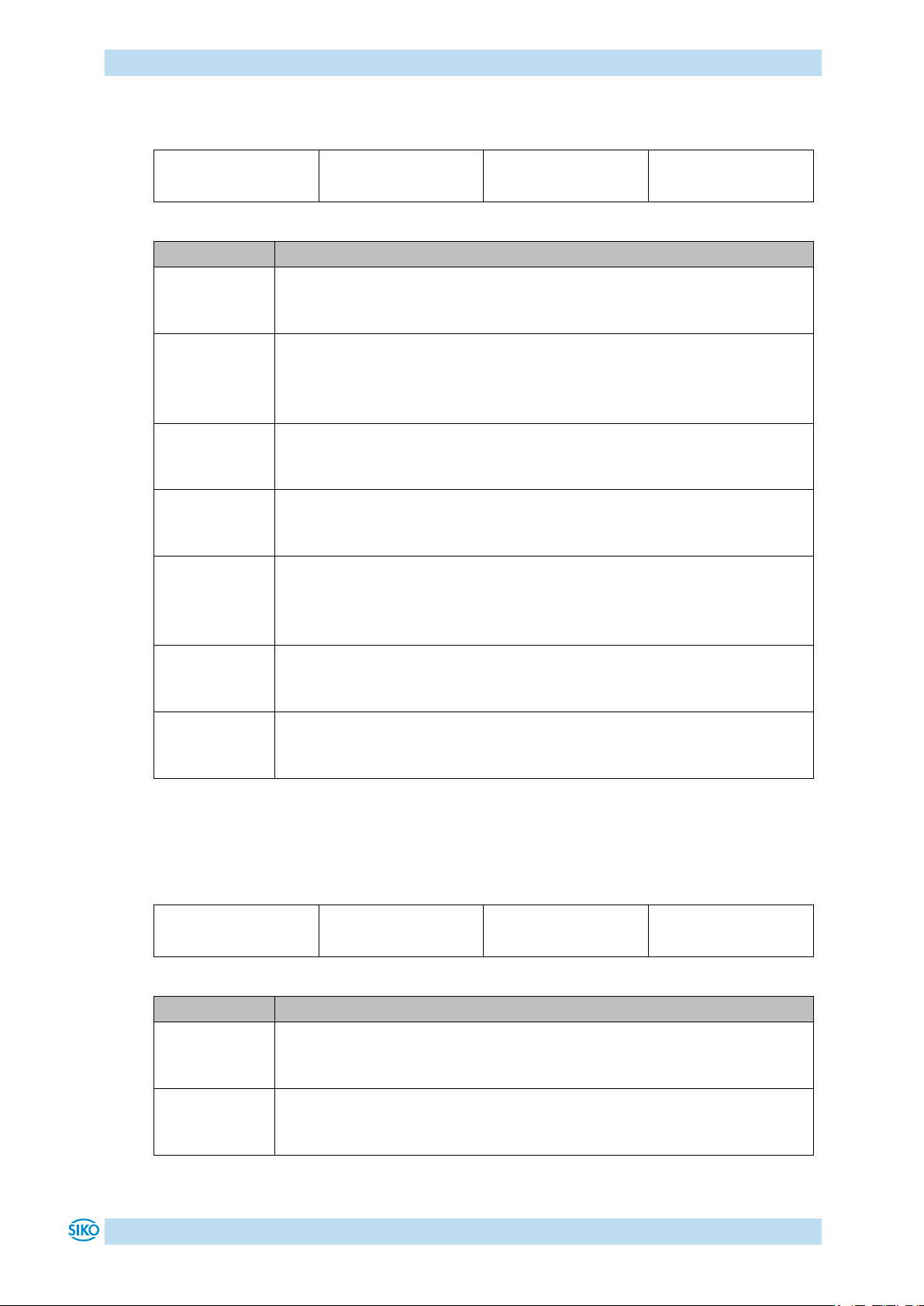
Menu
Sub-menu
Parameter
Description
Acceleration in the positioning mode
Value range: 1 – 100
(see chapter 8: Parameter description Parameter no. 4)
Maximum speed in the positioning mode
Gear 188:1 value range: 1 - 30
Gear 368:1 value range: 1 - 15
(see chapter 8: Parameter description Parameter no. 5)
Acceleration in rotational speed mode
Value range: 1 - 100
(see chapter 8: Parameter description Parameter no. 6)
Acceleration in inching mode 1/2
Value range: 1 - 100
(see chapter 8: Parameter description Parameter no. 8)
Maximum speed in inching mode 1/2
Gear 188:1 value range: 1 - 30
Gear 368:1 value range: 1 - 15
(see chapter 8: Parameter description Parameter no. 9)
Numerator gear ratio
Value range: 1 - 10000
(see chapter 8: Parameter description Parameter no. 11)
Denominator gear ratio
Value range: 1 - 10000
(see chapter 8: Parameter description Parameter no. 12)
Menu
Sub-menu
Parameter
Description
Limit 1
Value range: -19999 … 99999
(see chapter 8: Parameter description Parameter no. 15)
Limit 2
Value range: -19999 … 99999
(see chapter 8: Parameter description Parameter no. 16)
4.3.1.3 Actuator
Table 5: Actuator menu
4.3.1.4 Limiting values
AG06
Date: 07.02.2018 Art. No. 85674 Mod. status 055/18 Page 17 of 114
Page 18

Functional Description
Parameter
Description
Current limiting
Value range: 25 - 110
(see chapter 8: Parameter description Parameter no. 29)
Contouring error limit
Value range: 1 - 30000
(see chapter 8: Parameter description Parameter no. 28)
Menu
Sub-menu
Parameter
Description
Display orientation
Selection:
: 0°
: 180°
(see chapter 8: Parameter description Parameter no. 45)
LED 2 orange function
Selection:
: Bus operation display
: Off
(see chapter 8: Parameter description Parameter no. 39)
Red LED 1 function
Selection:
: Indication of the operating status
: Off
(see chapter 8: Parameter description Parameter no. 40)
Green LED 1 function
Selection:
: Indication of the operating status
: Off
(see chapter 8: Parameter description Parameter no. 41)
Decimal places
Selection:
: 0
: 0.0
: 0.00
: 0.000
: 0.0000
(see chapter 8: Parameter description Parameter no. 42)
Table 6: Limiting values menu
4.3.1.5 Visualization
AG06
Date: 07.02.2018 Art. No. 85674 Mod. status 055/18 Page 18 of 114
Page 19
Functional Description
Parameter
Description
Direction indication function
Selection:
: On
: inverted
: Off
(see chapter 8: Parameter description Parameter no. 44)
Displayed value of 2nd display line
Selection:
: Set point
: Output stage temperature
: Control voltage
: Output stage voltage
: Battery voltage
: Motor current
: Actual position
: Actual rotational speed
(see chapter 8: Parameter description Parameter no. 49)
Display test
Selection:
: no display test
: Start display test, pressing the key stops display test.
Menu
Sub-menu
Parameter
Description
Key enable time
Value range: 1 - 60
(see chapter 8: Parameter description Parameter no. 37)
Key function enable
Selection:
: Enable all key functions
: All key functions disabled
(see chapter 8: Parameter description Parameter no. 38)
Operating mode
Selection:
: Positioning mode
: Rotational speed mode
(see chapter 8: Parameter description Parameter no. 20)
Table 7: Visualization menu
4.3.1.6 Options
AG06
Date: 07.02.2018 Art. No. 85674 Mod. status 055/18 Page 19 of 114
Page 20

Functional Description
Parameter
Description
Delta Inch
Value range: -19999 … 99999
(see chapter 8: Parameter description Parameter no. 17)
Inpos mode
Selection:
: Position control to set point
: Position control Off and short circuit of all motor windings
: Position control Off and drive enable
(see chapter 8: Parameter description Parameter no. 26)
Inching mode 2 acceleration type
Selection:
: static acceleration
: incremental acceleration
(see chapter 8: Parameter description Parameter no. 31)
Stop mode inching 2
Selection:
: stop with maximum deceleration
: stop with programmed deceleration
(see chapter 8: Parameter description Parameter no. 25)
Inching 2 Offset
Value range: 10 - 100
(see chapter 8: Parameter description Parameter no. 30)
PIN change
Value range: 0 - 99999
(see chapter 8: Parameter description Parameter no. 48)
S commands
Selection:
: execute no S command
: Set all parameters to default
: Set standard parameters to default
: Set controller parameters to default
: Set display parameters to default
: Set bus parameters to default
: Calibration
: Delete error memory
Table 8: Options menu
AG06
Date: 07.02.2018 Art. No. 85674 Mod. status 055/18 Page 20 of 114
Page 21
Functional Description
Menu
Sub-menu
Parameter
Description
Controller parameter P
Value range: 1 - 500
(see chapter 8: Parameter description Parameter no. 1)
Controller parameter I
Value range: 0 - 500
(see chapter 8: Parameter description Parameter no. 2)
Controller parameter D
Value range: 0 - 500
(see chapter 8: Parameter description Parameter no. 3)
Menu
Parameter
Description
Current output stage temperature
Current control voltage
Current output stage voltage
Current battery voltage
Current motor current
Current actual position
Current actual speed
Gear reduction
Motor rated power
Encoder resolution
Display controller software version
Motor controller software version
Serial number
Production date
4.3.1.7 Controller parameters
Table 9: Controller parameters menu
4.3.2 Readable parameters
Table 10: Readable parameters menu
AG06
Date: 07.02.2018 Art. No. 85674 Mod. status 055/18 Page 21 of 114
Page 22
Calibration
Menu
Parameter
Description
Number of errors in the error memory
(see chapter 8: Parameter description Parameter no. 61)
xxxxx
Error 1
(see chapter 8: Parameter description Parameter no. 62)
xxxxx
Error 2
(see chapter 8: Parameter description Parameter no. 63)
xxxxx
Error 3
(see chapter 8: Parameter description Parameter no. 64)
xxxxx
Error 4
(see chapter 8: Parameter description Parameter no. 65)
xxxxx
Error 5
(see chapter 8: Parameter description Parameter no. 66)
xxxxx
Error 6
(see chapter 8: Parameter description Parameter no. 67)
xxxxx
Error 7
(see chapter 8: Parameter description Parameter no. 68)
xxxxx
Error 8
(see chapter 8: Parameter description Parameter no. 69)
xxxxx
Error 9
(see chapter 8: Parameter description Parameter no. 70)
xxxxx
Error 10
(see chapter 8: Parameter description Parameter no. 71)
4.3.3 Error memory
Table 11: Error memory menu
xxxxx = Plain text display of error codes (see chapter 7.2.1: Error codes)
5 Calibration
Since the measuring system is an absolute system, calibration is necessary only once with
commissioning. With calibration, the calibration value is adopted for calculation of the
position value. The following equation is applied in case of calibration:
Position value = 0 + calibration value + offset value
Writing a value onto the calibration value parameter (see chapter 8: Parameter description
Parameter no.14) will result in the adoption of such value as the absolute position for the
actuator.
Offset value (see chapter 8: Parameter description Parameter no. 32)
AG06
Date: 07.02.2018 Art. No. 85674 Mod. status 055/18 Page 22 of 114
Page 23
External gear
Calibration is only possible when no travel job is active!
5 revolution
1 revolution
Gear output
external
gear unit
5:1
M
internal drive
6 External gear
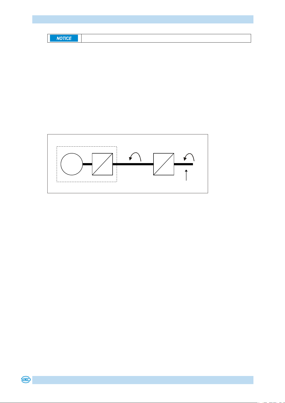
If an external gear is used, a factor can be programmed via the parameters no. 11 'ü –
numerator' and parameter no. 12 'ü – denominator' in order to include the gear ratio in
position sensing.
Example (see Fig. 7):
The actuator is operated on a gear with transmission reduction of 5:1. For this purpose, the
parameters 'ü-numerator' and 'ü-denominator' must be programmed as follows:
Parameter 'ü – numerator': 5
Parameter 'ü – denominator': 1
Fig. 7: External gear
Input of an odd gear transmission reduction value is possible according to the following
example:
Transmission reduction = 3.78
Parameter 'ü – numerator': 378
Parameter 'ü – denominator': 100
7 Warnings / Errors
7.1 Warnings
Warnings do not influence the operation of the positioning drive. Warnings disappear after
removing the cause.
Possible warnings:
Battery voltage for absolute encoder is below limit exchange battery within the next 6
months.
Current limiting active.
AG06
Date: 07.02.2018 Art. No. 85674 Mod. status 055/18 Page 23 of 114
Page 24
Warnings / Errors
Display
EMCY- Error codes
Error
00 00h
No error
FF 04h
Timeout client
FF 05h
Timeout host
FF 06h
Check sum client
FF 07h
Check sum host
FF 08h
Define mismatch
FF 09h
Low battery voltage
32 21h
Low control electronics voltage
32 11h
Excess control electronics voltage
32 12h
Excess power electronics voltage
43 10h
Output stage excess temperature
86 11h
Contouring error
71 21h
Shaft blocked
32 22h
Power electronics: not supplied
FF 0Ah
Unknown bus type
73 00h
SIN COS monitoring error
FF 0Bh
Queue 1 overrun
FF 0Ch
Queue 2 overrun
FF 0Dh
Response doesn't match question
FF 0Eh
Check sum EEPROM
FF 02h
Error Passive state occurred during an active travel
job.
FF 03h
Bus Off status
FF 0Fh
Queue 3 overrun
FF 10h
Queue 4 overrun
81 10h
CAN overrun
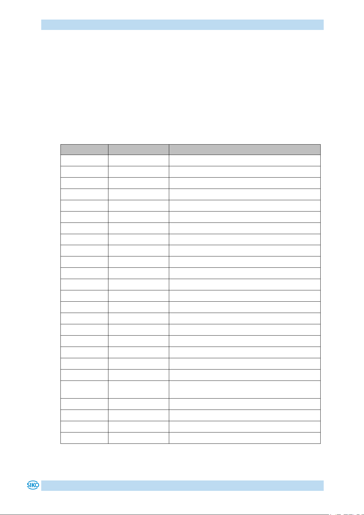
7.2 Errors
Errors cause an immediate stop of the positioning drive. Error states are signalled via display.
Via interface errors can also be detected:
The error messages are entered in the error memory in the order of their detection. The
last 10 error messages are displayed when the error memory is full.
The cause of error can be tracked down with the help of the error codes.
7.2.1 Error codes
Table 12: Error codes
AG06
Date: 07.02.2018 Art. No. 85674 Mod. status 055/18 Page 24 of 114
Page 25
Parameter description
Display
Description
Value range exceeded / inappropriate
Input value exceeds upper limit
Input value exceeds lower limit
Access nor supported
Write on read only
Read on write only
Error caused by device status
Input disabled due to ongoing EEPROM write access
Input disabled due to active travelling job
Programming lock activated
Column
Explanation
S
"S" = Parameter transferred is saved in the device non-volatilely
"-" = Parameter transferred is saved in the device volatilely
C
Parameter class
1 = Standard parameter
2 = Controller parameter
3 = Display parameter
4 = Bus parameter
5 = general parameter
No.
Name
Selection
/ value
Default
Description
S
C
1
Controller
parameter P
1 - 500
300
P gain of controller:
valid for all operating modes (positioning
mode, speed mode, inching mode)
S 2 2
Controller
parameter I
0 - 500
2
I gain of controller:
valid for all operating modes (positioning
mode, speed mode, inching mode)
S
2
3
Controller
parameter
D
0 - 500
0
D gain of controller:
valid for all operating modes (positioning
mode, speed mode, inching mode)
S
2
4
a - pos
1 - 100
50
Acceleration in the positioning mode:
values in %
100 % correspond to:
Gear 188:1 1.06 rps2
Gear 368:1 0.54 rps2
S
2
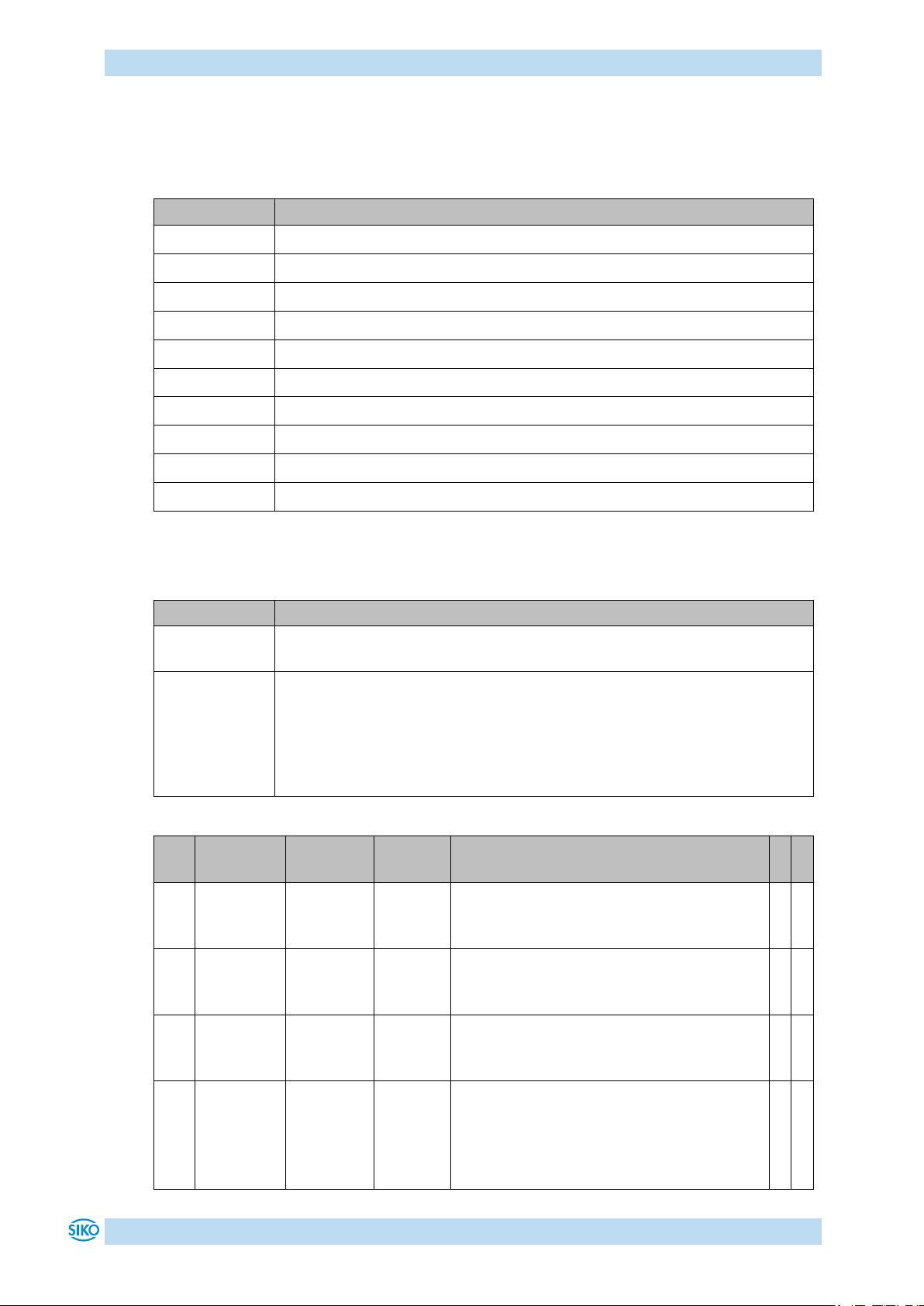
7.3 Input errors
Input errors inform the user abaut errors that occurred during menu entries. Entries that
produce errors are not adopted. Input errors are not saved in the error memory.
8 Parameter description
AG06
Date: 07.02.2018 Art. No. 85674 Mod. status 055/18 Page 25 of 114
Page 26

Parameter description
No.
Name
Selection
/ value
Default
Description
S
C
5
v - pos
see
Description
column
10
Maximum speed in the positioning mode:
values in rpm
Gear 188:1 1 – 30 rpm
Gear 368:1 1 – 15 rpm
S
2
6
a - rot
1 - 100
50
Acceleration in rotational speed mode:
values in %
100 % correspond to:
Gear 188:1 1.06 rps2
Gear 368:1 0.54 rps2
S
2
7 reserved
8
a - inch
1 - 100
50
Acceleration in inching mode 1/2:
values in %
100 % correspond to:
Gear 188:1 1.06 rps2
Gear 368:1 0.54 rps2
S
2
9
v - inch
see
Description
column
10
Maximum speed in inching mode 1/2:
values in rpm
Gear 188:1 1 – 30 rpm
Gear 368:1 1 – 15 rpm
S
2
10
Pos window
0 - 1000
10
Operating mode: Positioning mode:
Positioning window
If the actual position of the actuator is
within the programmed set point ± this
window, this is signalled by setting bit 3 in
the status word of the actuator.
Spindle pitch = 0: Values refer to increments
Spindle pitch > 0: Values refer to travel
distance in 1/100 mm
Operating mode: Speed mode:
If the actual rotational speed is within the
target rotational speed ± this window, this
is signalled by setting bit 3 in the system
status word of the actuator.
S
1
11
ü numerator
1 - 10000
1
Numerator gear ratio:
a gear factor can be programmed here when
a gear is used.
S 1 12
ü denominator
1 - 10000
1
Denominator gear ratio:
a gear factor can be programmed here when
a gear is used.
S
1
AG06
Date: 07.02.2018 Art. No. 85674 Mod. status 055/18 Page 26 of 114
Page 27

Parameter description
No.
Name
Selection
/ value
Default
Description
S
C
13
Spindle
pitch
0 1000000
0
Spindle pitch:
Spindle pitch parameter = 0:
Position value is output in increments (720
increments per revolution of the driving
shaft).
Spindle pitch parameter > 0:
(when operating the actuator on a spindle)
The position value is output as travelling
distance in 1/100 mm , not in increments.
Input of target position is now in 1/100 mm
as well.
e. g. spindle with a pitch of 2 mm
Spindle pitch parameter = 200.
S
1
14
Calibration
value
-999999 to
999999
0
Calibration value:
Changes in the calibration value will be
directly adopted for the calculation of the
position value.
Position value = 0 + calibration value +
offset value
S
1
15
Limit 1
-9999999
to 9999999
99999
Operating mode: Positioning mode: Limit
1
Spindle pitch = 0: Values refer to increments
Spindle pitch > 0: Values refer to travelling
distance in 1/100 mm
If actuator's position is beyond the range
defined by limit 1 and limit 2 (travel
range), travelling will only be possible in
inching mode in the direction of the travel
range.
Notice! Limit monitoring is deactivated if
'limit 1' is equal 'limit 2'. Please note that
there is a jump of the actual position if the
resolution of the absolute encoder is
exceeded!
Operating mode: Speed mode:
irrelevant
S
1
AG06
Date: 07.02.2018 Art. No. 85674 Mod. status 055/18 Page 27 of 114
Page 28

Parameter description
No.
Name
Selection
/ value
Default
Description
S
C
16
Limit 2
-9999999
to 9999999
-19999
Operating mode: Positioning mode: Limit
2
Spindle pitch = 0: Values refer to increments
Spindle pitch > 0: Information refers to
travel distance in 1/100 mm
If actuator's position is beyond the range
defined by limit 1 and limit 2 (travel
range), travelling will only be possible in
inching mode in the direction of the travel
range.
Notice! Limit monitoring is deactivated if
'limit 1' is equal 'limit 2'. Please note that
there is a jump of the actual position if the
resolution of the absolute encoder is
exceeded!
Operating mode: Speed mode:
irrelevant
S
1
17
Delta inch
-1000000
to 1000000
720
Delta travelling distance with inching
operation 1:
Indicates the relative travelling distance.
positive value positive travelling
direction
negative value negative travelling
direction
Spindle pitch = 0: Values refer to increments
Spindle pitch > 0: Information refers to
travel distance in 1/100 mm
S
1
18
Sense of
rotation
i, e
i
Counting direction of the measuring
system:
With shaft rotating counter-clockwise (view
on the clamping ring of the actuator)
i sense of rotation (cw): positive
counting direction
e sense of rotation (ccw): negative
counting direction
S
1
19
Pos Type
direct
loop +
loop -
direct
Operating mode: Positioning mode:
Type of positioning
direct: direct travelling from actual position
to set point
loop +: travelling to the set point occurs
always in positive direction to compensate
for spindle play
loop -: travelling to the set point occurs
always in negative direction to compensate
for spindle play
Notice! Loop positioning in positioning
mode only.
Operating mode: Speed mode:
irrelevant
S
1
AG06
Date: 07.02.2018 Art. No. 85674 Mod. status 055/18 Page 28 of 114
Page 29

Parameter description
No.
Name
Selection
/ value
Default
Description
S
C
20
Operating
mode
positioning
mode /
speed
mode
positioning mode
Operating mode: Positioning mode:
(see chapter 4.1.3.1: Positioning mode)
Operating mode: Speed mode:
(see chapter 4.1.3.3: Rotational speed
mode)
S
1
21 reserved
22
Node
address
1 - 127
1
Setting the CAN Node-ID
S
5
23 reserved
24
Set point
see
Description
column
0
Operating mode: Positioning mode:
Indicates absolute target position.
Spindle pitch = 0: Values refer to increments
Spindle pitch > 0: Information refers to
travel distance in 1/100 mm
Value range: depends on the preprogrammed
target values (parameters 15/16)
Operating mode: Speed mode:
indicates the target rotational speed in rpm
Value range:
Gear 188:1 max. ±30 rpm
Gear 368:1 max. ±15 rpm
-
1
25
Stop mode
Inch 2
0 - 1
0
Stop mode inching mode 2 / inching key
operation
Stopping behaviour of inching mode 2 or
inching key mode, resp., can be
parameterized differently.
Stop mode = 0 stop with maximum
deceleration
Stop mode = 1 stop with programmed
deceleration (Parameter no. 8)
S
1
26
Inpos mode
0 - 2
0
Operating mode: Positioning mode:
With this parameter you can define the
behaviour of the actuator upon reaching the
position window:
Inpos mode = 0 Position control to set
point
Inpos mode = 1 Position control OFF and
short circuit of the motor windings
Inpos mode = 2 Position control OFF and
drive enable
Operating mode: Speed mode:
irrelevant
S
1
27
Loop length
0 - 30000
360
Operating mode: Positioning mode:
Spindle pitch = 0: Values refer to increments
Spindle pitch > 0: values refer to travel
distance in 1/100 mm
Operating mode: Speed mode:
irrelevant
S
1
AG06
Date: 07.02.2018 Art. No. 85674 Mod. status 055/18 Page 29 of 114
Page 30

Parameter description
No.
Name
Selection
/ value
Default
Description
S
C
28
Contouring
error limit
1 - 30000
400
Contouring error limit:
Exceeding the contouring error limit during
ongoing positioning results in a "Contouring
error" fault.
S
1
29
Current
limiting
25 - 110
110
Current limiting:
Limiting of surge current. Figures indicate
percentage of nominal current
S
1
30
Inching 2
Offset
10 - 100
100
Inching operation 2:
The inching speed in Inching operation 2
can be influenced via this parameter Values
in percentage of parameter no. 9.
-
1
31
Type of
acceleration
Inching
mode 2
0 - 1
0
Inching operation 2:
The type of acceleration can be set with this
parameter.
0 = static acceleration
Acceleration to final speed in one step as
defined under parameter no. 8.
1 = incremental acceleration
Acceleration to final speed as defined under
parameter no. 8 with the following
increments:
4 s to 20 % of final speed
2 s to 50 % of final speed
1 s to 100 % of final speed
S
1
32
Offset
-999999 to
999999
0
Offset value
Changes to the offset value are immediately
entered in the calculation of the position
value.
The following equation is applied in case of
calibration:
Position value = 0 + calibration value +
offset value
S
1
33
Baud rate
CAN
1 - 7
3
Baud rate of the CAN interface:
1 = 1 Mbit/s
2 = 800 kbit/s
3 = 500 kbit/s
4 = 250 kbit/s
5 = 125 kbit/s
6 = 50 kbit/s
7 = 20 kbit/s
Parameter changes become active only after
cold start or software reset.
S
5
34 reserved
35 reserved
36 reserved
AG06
Date: 07.02.2018 Art. No. 85674 Mod. status 055/18 Page 30 of 114
Page 31

Parameter description
No.
Name
Selection
/ value
Default
Description
S
C
37
Key enable
time
1 - 60
3
Display / key control:
Time in seconds the asterisk key must be
held down until menu can be entered or the
set point specification is enabled via
display.
S
3
38
Key
function
enable
0 - 1
0
Display / key control:
The access to inching mode 2, positioning
mode and rotational speed mode functions
via keys can be set with this parameter.
0 = all functions via key enabled
1 = all functions via key disabled
S
3
39
LED 2
orange
0 - 1
1
LED 2 orange function:
0 = Off
1 = Bus operation indication
S
3
40
LED 1 red
0 - 1
1
Red LED 1 function:
0 = Off
1 = Indication of the operating status
S 3 41
LED 1 green
0 - 1
1
Green LED 1 function:
0 = Off
1 = Indication of the operating status
S
3
42
Decimal
places
0 - 4
0
Display:
Input of decimal places
0 = 0
1 = 0.0
2 = 0.00
3 = 0.000
4 = 0.0000
S
3
43
Display
divisor
0 - 3
0
Display:
Divisor by which the display accuracy is
reduced compared with the measurement
resolution.
0 = 1
1 = 10
2 = 100
3 = 1000
S
3
44
Direction
indication
function
0 - 2
0
Display:
The direction indicators show the key to be
pressed to arrive at the set position
window.
0 = On
1 = Inverted
2 = Off
S
3
45
Display
orientation
0 - 1
0
Display:
Display orientation
0 = 0°
1 = rotated by 180°
S
3
46 reserved
47 reserved
AG06
Date: 07.02.2018 Art. No. 85674 Mod. status 055/18 Page 31 of 114
Page 32

Parameter description
No.
Name
Selection
/ value
Default
Description
S
C
48
PIN Change
0 - 99999
0
Display:
Required PIN to be able to change
parameters via keys and display.
S
3
49
Displayed
value 2nd
display line
0 - 7
0
Display:
Parameter to be displayed in the 2nd line of
the display.
0 = Set point
1 = Output stage temperature
2 = Control voltage
3 = Output stage voltage
4 = Battery voltage
5 = Motor current
6 = Actual position
7 = Actual rotational speed
S
3
50
Output
stage
temperature
Read only
-
Output stage temperature:
Values in 1/10 °C
-
-
51
Voltage of
control
Read only
-
Control voltage:
Values in 1/10 V
-
-
52
Voltage of
output
stage
Read only
-
Output stage voltage:
Values in 1/10 V
-
53
Voltage of
battery
Read only
-
Battery voltage:
Values in 1/100 V
-
-
54
Motor
current
Read only
-
Motor current:
Values in mA
-
-
55
Actual
position
Read only
-
Actual position:
Spindle pitch = 0: values in increments
Spindle pitch > 0: values in 1/100 mm
-
-
56
Actual
rotational
speed
Read only
-
Actual rotational speed:
Values in rpm
-
57
Serial
number
Read only
-
Serial number
S
-
58
Production
date
Read only
-
Production date:
Format: DDMMJJJJ
S
-
59
Software
version
motor
controller
Read only
-
Motor controller software version
S
-
60
Software
version
display
controller
Read only
-
Display controller software version
S
-
61
Number of
errors
Read only
-
Number of errors in the error memory
S
-
AG06
Date: 07.02.2018 Art. No. 85674 Mod. status 055/18 Page 32 of 114
Page 33
Communication via CAN bus
No.
Name
Selection
/ value
Default
Description
S
C
62
Error 1
Read only
-
Error 1
S - 63
Error 2
Read only
-
Error 2
S
-
64
Error 3
Read only
-
Error 3
S
-
65
Error 4
Read only
-
Error 4
S - 66
Error 5
Read only
-
Error 5
S - 67
Error 6
Read only
-
Error 6
S
-
68
Error 7
Read only
-
Error 7
S - 69
Error 8
Read only
-
Error 8
S
-
70
Error 9
Read only
-
Error 9
S - 71
Error 10
Read only
-
Error 10
S
-
72
Gear
reduction
Read only
-
Gear reduction
S
-
73
System
Status Word
Read only
-
System status word
-
-
74
Display
divisor
application
0 - 1
0
Positioning mode only:
0 = The display divisor is applied to the
interface's target and actual positions and
to the display.
1 = The display divisor is applied to the
display only.
S
3
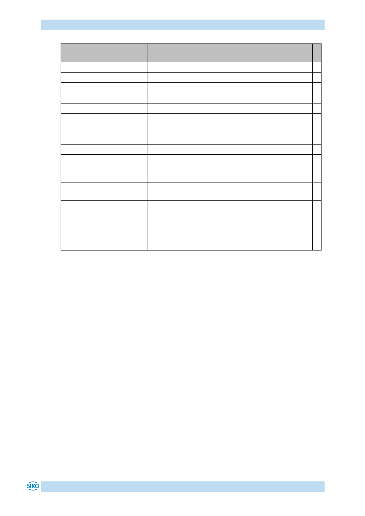
Table 13: Parameter description
9 Communication via CAN bus
9.1 General remarks
This chapter describes activation and parameterization via CAN bus interface.
For the connector pin assignment of the CAN bus interface please refer to the installation
instructions.
9.1.1 Interface
The following baud rates are supported:
1 Mbit/s, 800 kbit/s, 500 kbit/s, 250 kbit/s, 125 kbit/s, 50 kbit/s, 20 kbit/s
Termination of the CAN bus line:
If the actuator is at the end of the bus, the CAN bus connection must be terminated by a
defined bus terminator.
AG06
Date: 07.02.2018 Art. No. 85674 Mod. status 055/18 Page 33 of 114
Page 34
Communication via CAN bus
High Byte
Low Byte
Bit number
15
14
13
12
11
10 9 8 7 6 5 4 3 2 1 0 0 0 1 0 1 0 0 1 0 1 0 0 1 0 0 0
2 9 4
8
Bit
State
Description
Bit 0
'0'
irrelevant
Bit 1
'0'
irrelevant
Bit 2
'0'
irrelevant
Bit 3
Operating mode: Positioning mode In Position
'1'
Actual position is within the positioning window of the programmed set point.
'0'
Actual position is beyond the positioning window of the programmed set point.
Operating mode: Speed mode: In Position
'1'
Actual rotational speed is within the specified tolerance window of the
target speed.
'0'
Actual speed is outside the specified tolerance window.
Bit 4
Actuator travels:
'1'
Actuator travels.
'0'
Drive stands still (rotational speed <2 rpm).
Bit 5
Operating mode: Positioning mode, upper limit
'1'
Actual position is above the programmed limiting value. Travelling is
possible only in negative direction in inching mode.
'0'
Actual position is below the programmed limiting value.
'0'
Operating mode: Speed mode: irrelevant
Bit 6
Operating mode: Positioning mode, lower limit
'1'
Actual position is below the programmed limiting value. Travelling is
possible only in positive direction in inching mode.
'0'
Actual position is above the programmed limiting value.
'0'
Operating mode: Speed mode: irrelevant
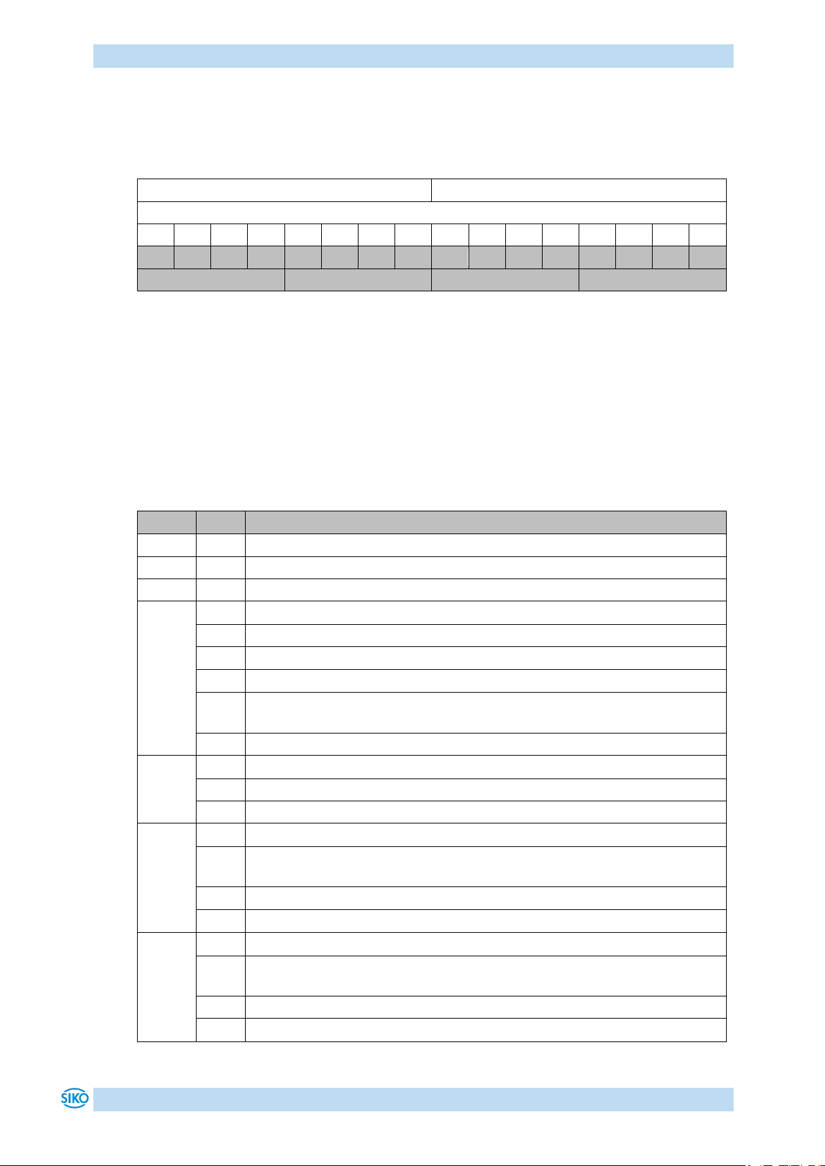
9.2 System Status Word
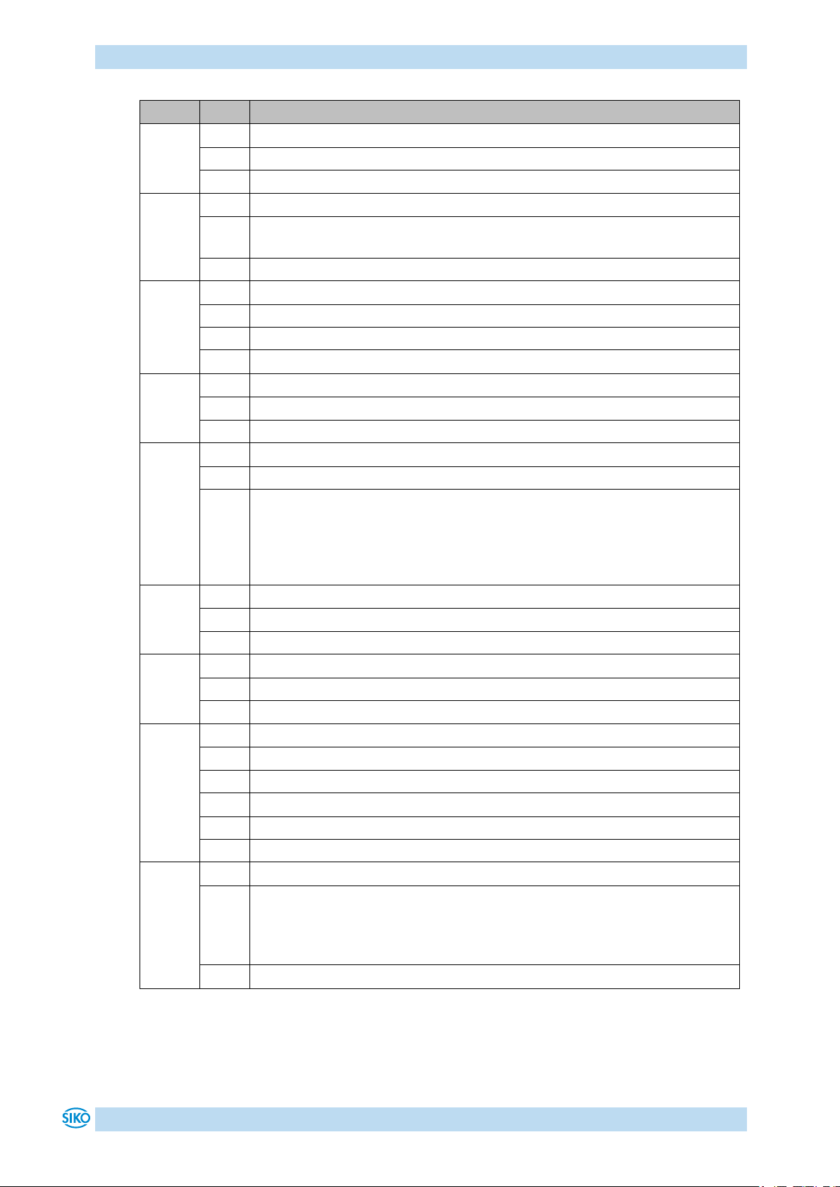
The system status word consists of 2 bytes and reflects the state of the actuator (see chapter
8: Parameter description Parameter no. 73).
Table 14: Structure of system status word
Example (grey background):
binary: 0010 1001 0100 1000
hex: 2 9 4 8
9.2.1 Meaning of the bits
The table below informs about the meaning of the individual bits of the status word:
AG06
Date: 07.02.2018 Art. No. 85674 Mod. status 055/18 Page 34 of 114
Page 35
Communication via CAN bus
Bit
State
Description
Bit 7
Driver state:
'1'
Motor is enabled.
'0'
Motor in control.
Bit 8
Error:
'1'
Actuator has switched to error. The cause of the error must be removed and
acknowledged.
'0'
No error present.
Bit 9
Operating mode: Positioning mode: Loop travel
'1'
If travel direction unequal start direction (with loop travel).
'0'
If travel direction equal start direction.
'0'
Operating mode: Speed mode: irrelevant
Bit 10
Output stage supply voltage:
'1'
No voltage, no travelling possible.
'0'
Voltage applied.
Bit 11
Ready for travel:
'1'
Not ready for travel
'0'
Ready for travel:
- Actuator not in error state
- No active positioning
- Supply voltage of the output stage is applied
- Actual position within limits (only positioning mode)
Bit 12
Battery voltage:
'1'
Battery voltage <2.6 V
'0'
Battery voltage o. k.
Bit 13
Current limiting:
'1'
Current limiting active.
'0'
Current limiting not active.
Bit 14
Operating mode: Positioning mode Status
'1'
Positioning active in positioning mode.
'0'
Positioning inactive.
Operating mode: Speed mode: Status
'1'
Enable target speed.
'0'
Target speed disabled.
Bit 15
Contouring error:
'1'
Contouring error the actuator cannot reach the pre-set speed due to too
high load.
The actuator switches the contouring error fault.
Remedy: reduce programmed speed!
'0'
No contouring error actual speed corresponds to target speed.
Table 15: System Status Word
AG06
Date: 07.02.2018 Art. No. 85674 Mod. status 055/18 Page 35 of 114
Page 36

Communication via CAN bus
Control field
F
S
O
Identifier
CRC
ACK / EOF
CRC
Data field (max. 8byte)
9.3 CANopen protocol
The CANopen protocol is based on the CANopen communication profile CiA DS-301 V4.0 as
well as the device profile Drives and Motion Control CiA DSP-402 V2.0.
The details required for a better understanding and possible deviations are included in this
documentation.
9.3.1 Telegram setup
The data telegram of a CAN message consists of the following fields:
SOF:
Start of Frame start bit of the telegram
Identifier:
The Identifier field contains the identifier as well as bits for the recognition of the length of
the identifiers (11 or 29 bits). The identifier determines the priority of the message. Via
identifier, CANopen determines additionally the device address, channel selection as well as
data direction.
Control field:
Contains bits concerning the number of user data and determines whether a data frame or RTR
frame (Remote Transfer Request frame) is concerned.
Data field:
Contains up to 8 bytes of user data. The user data has a different meaning depending on the
hannel selection.
CRC:
Contains bits for error detection.
ACK/EOF:
The ACK/EOF field contains telegram acknowledgement bits as well as bits for determining the
end of telegram.
Fig. 8: Telegram setup
For a detailed description of the telegram please refer to the comprehensive CAN literature.
For simplification, only identifier and data field will be dealt with in the subsequent telegram
descriptions.
AG06
Date: 07.02.2018 Art. No. 85674 Mod. status 055/18 Page 36 of 114
Page 37
Communication via CAN bus
PDO parameters can be changed in this state only!
Power on or Software Reset
Initialisation
BootUp Message
1
2 2 3 3 4/5
4/5
4/5
1
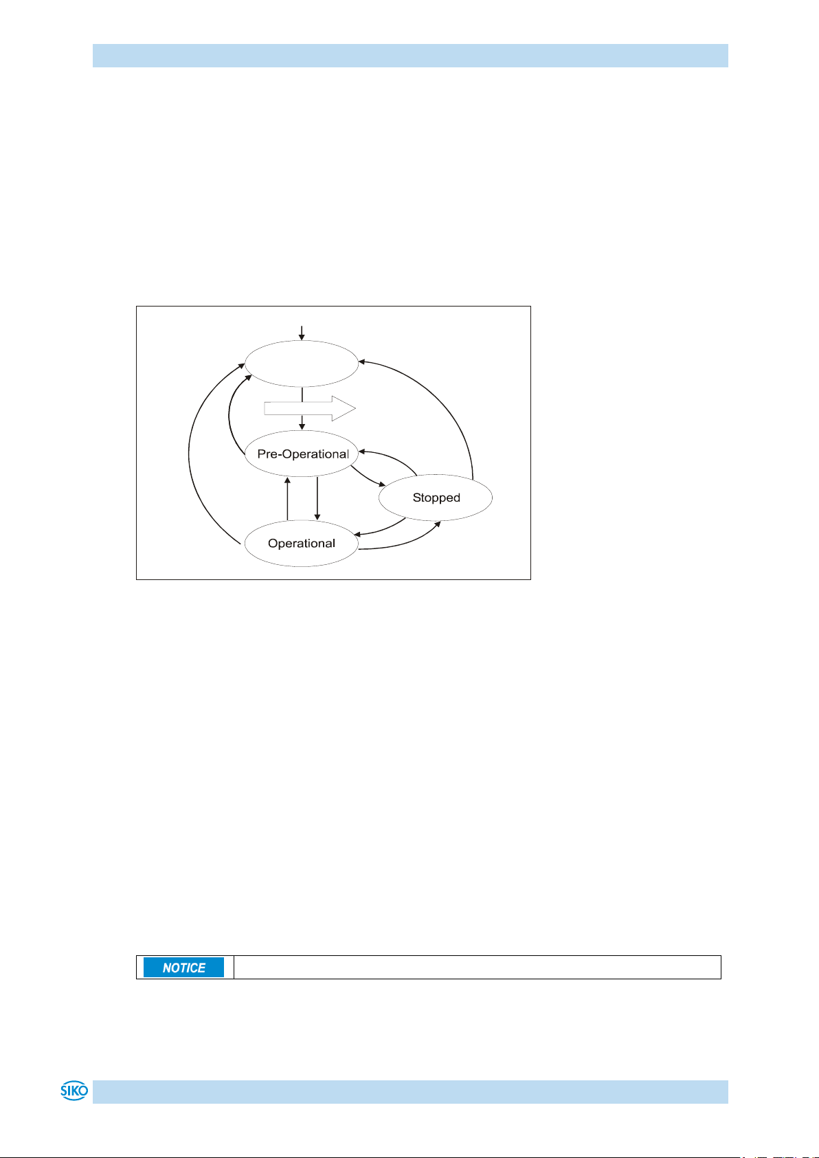
9.3.2 Network management (NMT)
The master configures, manages and monitors network nodes via the NMT service.
For switching between the four available communication states of a network node,
'INITIALISATION', 'PRE-OPERATIONAL', 'OPERATIONAL' and 'STOPPED', telegrams with the
identifier '0' as well as 2 bytes of user data are used. The identifier of the NMT protocol is
limited to 11 bits.
9.3.2.1 State Diagramm
Fig. 9: State Diagramm
9.3.2.2 NMT Status 'INITIALISATION'
The actuator is not involved in the bus actions in this state. All hardware and software
components are initialised. This state is attained after switching on the device or after receipt
of the command code 82h of the own or global addresses. After completion of initialisation,
the actuator goes automatically into the 'PRE-OPERATIONAL' status. This is signalled by a
boot-up message consisting of the identifier '1791 + Node ID' and a data byte having the
value '0'.
9.3.2.3 NMT Status 'PRE-OPERATIONAL'
The exchange of parameterization data (SDOs) between the actuator and the bus master is
enabled. However, no process data (PDOs) is transferred. Furthermore, the State Machine of
the actuator is set to the 'SWITCH ON DISABLED' state (see chapter 9.4: State Machine) and
the motor enabled.
AG06
Date: 07.02.2018 Art. No. 85674 Mod. status 055/18 Page 37 of 114
Page 38
Communication via CAN bus
Status change
Data 1
Data 2
from
to
PRE-OPERATIONAL / STOPPED
OPERATIONAL (1)
01h
xx
OPERATIONAL / PRE-OPERATIONAL
STOPPED (2)
02h
xx
OPERATIONAL / STOPPED
PRE-OPERATIONAL (3)
80h
xx
OPERATIONAL / PRE-OPERATIONAL / STOPPED
INITIALISATION (4/5)
81h
xx
OPERATIONAL / PRE-OPERATIONAL / STOPPED
INITIALISATION * (4/5)
82h
xx
9.3.2.4 NMT Status 'OPERATIONAL'
Exchange of process and parameterization data is enabled.
Hint: TPDOs with the 254 transfer type are sent with the transition into the 'OPERATIONAL'
NMT status.
9.3.2.5 NMT Status 'STOPPED'
Exchange of all data is stopped with the exception of the heartbeat message (see chapter
9.3.10: Heartbeat protocol) and the node guarding protocol, if active (see chapter 9.3.11:
Node Guarding). Only NMT communication is enabled. Furthermore, the State Machine of the
actuator is set to the 'SWITCH ON DISABLED' state (see chapter 9.4: State Machine) and the
motor enabled.
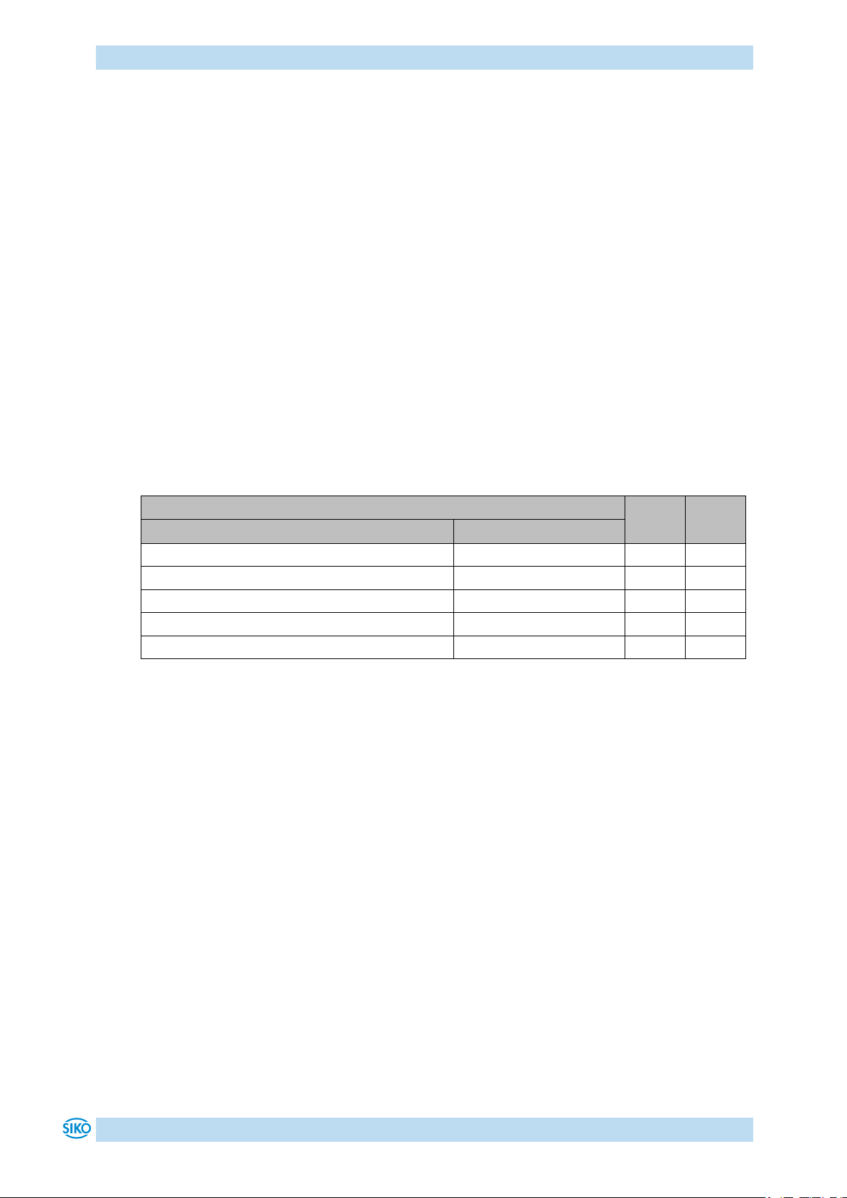
9.3.2.6 Switching between communication states
The network master can switch between the communication states by sending the following
telegrams with the identifier '0'.
Table 16: Switching between communication state
* Cold start is triggered (Power on)
xx = 0 the telegram is intended for all devices on the bus
xx = device address the telegram is only intended for the device with the respective
9.3.3 SYNC-Objekt
CANopen enables the simultaneous query of all inputs and the simultaneous setting of all
outputs. The synchronization telegram (SYNC), a CAN message with high priority, which
contains no user data serves for this purpose.
The identifier of the Sync object can be set via object 1005h (see chapter 9.13.2: Description
of objects).
address.
AG06
Date: 07.02.2018 Art. No. 85674 Mod. status 055/18 Page 38 of 114
Page 39
Communication via CAN bus
The exchange of PDOs is enabled in the NMT status Operational only!
1st Transmit PDO
11/29 Bit Identifier
Byte 1
Byte 2
LSB
MSB
Status word (object 6041h)
9.3.4 Process Data Objects (PDOs)
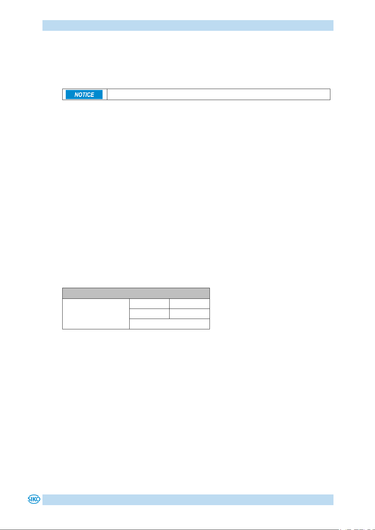
Process data objects serve for fast exchange of short process data. Process data objects are
transferred event-triggered, cyclically or on request. A maximum of 8 bytes of user data can
be transferred in a PDO.
The actuator provides 3 Transmit PDOs (process data from the actuator NMT master) and 3
Receive PDOs (process data from the NMT master to the actuator). The Receive PDOs,
RPDO1, RPDO3, RPDO4 and the Transmit PDOs, TPDO1, TPDO3 and TPDO4 are supported
according to the Device Profil 'Drives and Motion Control CIA DSP-402 Version 2.0'.
9.3.5 Transmit-PDOs
9.3.5.1 1
9.3.5.2 3
st
Transmit PDO (TPDO1)
The first Transmit PDO contains 2 user data bytes on which the status word of the actuator is
mapped.
The Transmit PDO is transferred by the actuator asynchronously as a standard. Together with
the Receive PDO1 on which the control word of the state machine is mapped it forms a
handshake connection (acknowledgement operation) between the higher-order control and
the drive controller.
It is, therefore not recommended to change the transfer type of the TDO1.
The COB-ID of the first Transmit PDO is programmed to 180h + Node-ID by default. The
communication parameters are set via the object 1800h (1st Transmit PDO parameter).
Table 17: 1st Transmit PDO
rd
Transmit PDO (TPDO3)
The third Transmit PDO contains 6 user data bytes on which the status word and the current
position value of the actuator are mapped.
The Transmit PDO3 is transferred only by a RTR frame (remote transfer request) as a standard,
i. e., a higher-order control must request the TDO3 (polling). Synchronous transfer (value 0 to
240) can be set via the SYNC object or the time-triggered transfer (value 255) by means of a
local cycle (event timer) as an alternative to polling.
The COB-ID of the third Transmit PDO is programmed to 380h + Node-ID by default. The
communication parameters are set via the object 1802h (3rd Transmit PDO parameter).
AG06
Date: 07.02.2018 Art. No. 85674 Mod. status 055/18 Page 39 of 114
Page 40
Communication via CAN bus
3rd Transmit PDO
11/29 Bit Identifier
Byte 1
Byte 2
Byte 3
Byte 4
Byte 5
Byte 6
LSB
MSB
LSB
NSB
NSB
MSB
Status word (object
6041h)
Position value (object 6064h)
4th Transmit PDO
11/29 Bit Identifier
Byte 1
Byte 2
Byte 3
Byte 4
Byte 5
Byte 6
LSB
MSB
LSB
NSB
NSB
MSB
Status word (object
6041h)
Actual velocity (object 606Ch)
Table 18: 3rd Transmit PDO
9.3.5.3 4
th
Transmit PDO (TPDO4)
The fourth Transmit PDO contains 6 user data bytes on which the status word and the actual
velocity of the actuator is mapped. The Transmit PDO4 is transferred only by a RTR frame
(remote transfer request) as a standard, i. e., a higher-order control must request the TDO4
(polling). Synchronous transfer (value 0 to 240) can be set via the SYNC object or the timetriggered transfer (value 255) by means of a local cycle (event timer) as an alternative to
polling.
The COB-ID of the fourth Transmit PDO is programmed to 480h + Node-ID by default. The
communication parameters are set via the object 1803h (4th Transmit PDO parameter).
Table 19: 4th Transmit PDO
9.3.5.4 Transfer types of the Transmit PDOs
AG06
Different transfer types can be set for the individual PDOs via objects 1800h until 1803h
'Transmit PDO Parameter' sub-index 2 (see chapter 9.13.2: Description of objects).
Synchronous:
Sub-index 2 (transfer type) = 0:
The Transmit PDO is sent by the actuator upon receipt of each SYNC telegram.
Sub-index 2 (transfer type) = 1 ... 240:
The Transmit PDO is sent by the actuator only after receipt of the number of SYNC telegrams
indicated under 'transfer type'.
Asynchronous:
Event-Triggered: Sub-index 2 (transfer type) = 254
A PDO is transfmitted with every change of a mapped object and in a time-controlled way. The
Event Timer can be deactivated.
Time-Triggered: Sub-index 2 (transfer type) = 255
The PDOs are transferred time-triggered.
Date: 07.02.2018 Art. No. 85674 Mod. status 055/18 Page 40 of 114
Page 41
Communication via CAN bus
1st Receive PDO
11/29 Bit Identifier
Byte 1
Byte 2
LSB
MSB
Control word (object 6040h)
The sub-index 5 'Event Timer' of the Transmit PDO parameters indicates the cycle time in
milliseconds.
Sub-index 2 (transfer type) = 253
The Transmit PDO is sent after receipt of a RTR frame with the identifier of the respective
Transmit PDO.
9.3.6 Receive-PDOs
9.3.6.1 1
st
Receive PDO (RPDO1)
The first Receive PDO contains 2 user data bytes on which the status word of the actuator is
mapped.
The control word in the Receive PDO1 serves for controlling the operation transitions of the
state machine. The Receive PDO1 serves for getting the state machine into the OPERATION
ENABLED state or for commanding travel interruption or cancellation of travel during running
drive movement, respectively.
The drive controller processes the Receive PDO1 asynchronously as a standard. Together with
the Transmit PDO1 on which the control word of the state machine is mapped it forms a
handshake connection (acknowledgement operation) between the higher-order control and
the drive controller.
It is, therefore not recommended to change the transfer type of the RPDO1.
The COB-ID of the first Receive PDO is programmed to 200h + Node-ID by default. The
communication parameters are set via the object 1400h (1st Receive PDO parameter).
9.3.6.2 3
AG06
Table 20: 1st Receive PDO
rd
Receive PDO (RPDO3)
The third Receive PDO is assigned to the operation mode 'Profile Position Mode' (positioning
mode) and contains 6 user data bytes on which the control word as well as the current target
value for the actuator is mapped.
The position transferred is taken over as the absolute target position. Drive movement in the
positioning mode can be executed from the 'OPERATION ENABLED' state of the state machine
only.
The drive controller processes the Receive PDO3 asynchronously as a standard. Together with
the Transmit PDO1 on which the status word of the state machine is mapped, it forms a
handshake connection (acknowledgement operation) between the higher-order control and
the drive controller.
Synchronous transfer type (value 0) can be set to enable synchronous start of more than one
drive. The data of the RPDO3 is processed only after receipt of the next SYNC telegram in this
case (see chapter 9.3.3: SYNC-Objekt).
Date: 07.02.2018 Art. No. 85674 Mod. status 055/18 Page 41 of 114
Page 42
Communication via CAN bus
3rd Receive PDO
11/29 Bit Identifier
Byte 1
Byte 2
Byte 3
Byte 4
Byte 5
Byte 6
LSB
MSB
LSB
NSB
NSB
MSB
Control word (object
6040h)
Target value (object 607Ah)
4th Receive PDO
11/29 Bit Identifier
Byte 1
Byte 2
Byte 3
Byte 4
Byte 5
Byte 6
LSB
MSB
LSB
NSB
NSB
MSB
Control word (object
6040h)
Target velocity (object 60FFh)
The COB-ID of the third Transmit PDO is programmed to 400h + Node-ID by default. The
communication parameters are set via the object 1402h (3rd Receive PDO parameter).
Table 21: 3rd Receive PDO
9.3.6.3 4
th
Receive PDO (RPDO4)
The fourth Receive PDO is assigned to the operation mode 'Velocity Mode' and contains 6 user
data bytes on which the control word as well as the current target velocity for the actuator
are mapped.
A driving movement in positive or negative sense of rotation is started via the control word in
the Receive PDO4. Drive movement in the velocity mode can be executed from the 'OPERATION
ENABLED' state of the state machine only.
The drive controller processes the Receive PDO4 asynchronously as a standard. Together with
the Transmit PDO1 onto which the status word of the state machine is mapped, it forms a
handshake connection (acknowledgement operation) between the higher-order control and
the drive controller.
Synchronous transfer type (value 0) can be set to enable synchronous start of more than one
drive. The data of the RPDO4 is processed only after receipt of the next SYNC telegram in this
case (see chapter 9.3.3: SYNC-Objekt).
The COB-ID of the fourth Transmit PDO is programmed to 500h + Node-ID by default. The
communication parameters are set via the object 1403h (4th Receive PDO parameter).
Table 22: 4th Receive PDO
9.3.6.4 Transfer types of the Receive PDOs
Different transfer types can be set for the individual PDOs via objects 1400h until 1403h
'Receive PDO Parameter' sub-index 2 (see chapter 9.13.2: Description of objects).
Synchronous:
Sub-index 2 (transfer type) = 0 ... 240
In the synchronous transfer type, the Receive PDOs are processed only after receipt of a SYNC
telegram.
AG06
Date: 07.02.2018 Art. No. 85674 Mod. status 055/18 Page 42 of 114
Page 43
Communication via CAN bus
The exchange of SDOs is enabled in the NMT statuses "Pre-Operational" as
well as "Operational"!
SDO Telegram
11 Bit
Identifier
Byte 1
Byte 2
Byte 3
Byte 4
Byte 5
Byte 6
Byte 7
Byte 8
Command
Parameter index
Sub-index
Data 1
Data 2
Data 3
Data 4
Command
Command code
hexadecimal
Command
code decimal
Meaning
Write Request
23h
35
send parameters (4 data byte)
Write Request
2Bh
43
send parameters (2 data byte)
Write Request
2Fh
47
send parameters (1 data byte)
Write Response
60h
96
response of Write Request
Read Request
40h
64
request of a parameter
Read Response
43h
67
response to the request (4 data byte)
Read Response
4Bh
75
response to the request (2 data byte)
Read Response
4Fh
79
response to the request (1 data byte)
Error Response
80h
128
error message
Asynchronous:
Sub-index 2 (transfer type) = 254 ... 255
In the asynchronous transfer type, the Receive PDOs are processed by the actuator
immediately after receipt of the Receive PDO.
9.3.7 Service Data Objects (SDOs)
Service Data Objects (SDOs) serve in the first place for transferring device configuration
parameters.
8 bytes of user data are always transferred in a SDO. The identifier is set to 11 bits and cannot
be changed.
There is each one COB ID for data transfer from the master to the actuator (COB-ID 600h +
Node-ID) and one COB ID for data transfer from the actuator to the master (COB-ID 580h +
Node-ID).
Data transfer is always initiated and controlled by the master.
The COB IDs for the Service Data Objects cannot be changed.
Table 23: Setup of the SDO telegram
Byte 1: Command code
The first byte contains the command code of the SDO telegram. The following table lists the
available commands and describes their meaning.
Table 24: Command codes
AG06
Date: 07.02.2018 Art. No. 85674 Mod. status 055/18 Page 43 of 114
Page 44
Communication via CAN bus
Command code
Data 1
Data 2
Data 3
Data 4
Meaning
80h
11h
00h
09h
06h
Sub-Index not exist.
80h
02h
00h
01h
06h
Attempt to write read only object.
80h
01h
00h
01h
06h
Attempt to read write only object.
80h
30h
00h
09h
06h
Value range of parameter exceeded.
80h
36h
00h
09h
06h
Maximum value is less than
minimum value.
80h
00h
00h
02h
06h
Object does not exist.
80h
00h
00h
01h
06h
Unsupportet access to an object.
80h
22h
00h
00h
08h
Data cannot be transferred to the
application because of the present
device state.
Bytes 2/3: Parameter index
The parameter index is entered in the user data byte 2 (low byte) and in the user data byte 3
(high byte) using ther Intel data format.
Here, the index of the object to be parameterized is entered (see chapter 9.13.2: Description
of objects).
Byte 4: Sub-index
The sub-index indicates the number of the fields for objects realized as an array.
Bytes 5 ... 8: Data area
In the data area, the value of the parameter is entered in left-aligned Intel notation.
Byte 5 = low-Byte ... Byte 8 = high Byte
9.3.7.1 Error code
The actuator sends an error response (byte 1 = 80h) if a communication error has occurred. An
error code is entered in the user data bytes (bytes 5 … 8). The table below shows the
supported error codes.
Table 25: Error codes
9.3.8 Example: Parameterization
The following 2 examples are intended to illustrate parameterization via Service Data Objects.
9.3.8.1 Example: Read parameter
The actuator has device address 5 and the calibration value is to be read out!
Calculation of the identifier:
Identifier of the parameter channel to the actuator = 600h + device address
600h = 1536
AG06
dec
Date: 07.02.2018 Art. No. 85674 Mod. status 055/18 Page 44 of 114
Page 45
Communication via CAN bus
Identifier
Byte 1
Byte 2
Byte 3
Byte 4
Byte 5
Byte 6
Byte 7
Byte 8
605h
40h
7Ch
60h
00h
00h
00h
00h
00h
Identifier
Byte 1
Byte 2
Byte 3
Byte 4
Byte 5
Byte 6
Byte 7
Byte 8
585h
42h
7Ch
60h
00h
C4h
09h
00h
00h
Identifier
Byte 1
Byte 2
Byte 3
Byte 4
Byte 5
Byte 6
Byte 7
Byte 8
605h
23h
7Dh
60h
02h
80h
84h
1Eh
00h
Identifier
Byte 1
Byte 2
Byte 3
Byte 4
Byte 5
Byte 6
Byte 7
Byte 8
585h
60h
7Dh
60h
02h
00h
00h
00h
00h
Identifier = 1536 + 5 = 1541 = 605h
Command code = Read request (= request of a parameter from the actuator) = 40h
Index = 607Ch
The index of the parameter calibration value was taken from the directory of objects (chapter
9.13.2: Description of objects).
Sub-index= 0
The current calibration value is 2500 = 9C4h.
Telegram from the master to the actuator:
Response of the actuator:
Command code = Read Response = 42h
Calculation of the identifier:
Identifier of the parameter channel from the actuator to the master = 580h + device address
580h = 1408
dec
Identifier = 1408 + 5 = 1413 = 585h
9.3.8.2 Example: Write parameter
For the actuator with device address 5 the limit 1 is to be set to 2000000!
Calculation of the identifier:
Identifier of the parameter channel to the actuator = 600h + device address
600h = 1536
dec
Identifier = 1536 + 5 = 1541 = 605h
Command code = Write request (send parameter to the actuator) = 23h
Index = 607Dh
Sub-index = 2
The index and the sub-index of the parameter 'limit 1' were taken from the directory of
objects (chapter 9.13.2: Description of objects).
2000000 = 1E8480h
Telegram from the master to the actuator:
Response of the actuator in the case of error-free execution:
AG06
Date: 07.02.2018 Art. No. 85674 Mod. status 055/18 Page 45 of 114
Page 46
Communication via CAN bus
Identifier
Byte 0
Byte 1
Byte 2
Byte 3
Byte 4
Byte 5
Byte 6
Byte 7
11/29 Bit
Emergency Error
Code (see chapter
9.3.9)
Error
Register
(Object
1001h)
Manufacturer-specific error field (not used)
Error Code
Meaning
Byte 0
(Highbyte)
Byte 1
(Lowbyte)
00
00h
No error (no fault present)
Is sent after clearing the fault state (see chapter 7.2: Errors).
32
11h
Control Overvoltage
The state machine was set to the 'Fault' state.
Fault is deposited in the fault buffer.
32
12h
Power Overvoltage
The state machine was set to the 'Fault' state.
Fault is deposited in the fault buffer.
Command code = Write Response = 60h
Calculation of the identifier:
Identifier of the parameter channel from the actuator to the master = 580h + device address
580h = 1408
dec
Identifier = 1408 + 5 = 1413 = 585h
9.3.9 Emergency Object (EMCY)
In the case of an error, the node status is transferred via high-priority emergency messages
(emergency telegrams). These telegrams have a data length of 8 bytes and contain error
information.
The emergency telegram is transferred as soon as the actuator goes into the fault state (for
the causes of faults refer to chapter 7.2: Errors) or when a communication error has occurred
(see Table 27: Error-Code 8110h – 8140h).
Resolution of the cause of fault and resetting of the actuator with undoing the fault state are
signalled by sending of an emergency telegram with the error code 0000h (no error) (not
applicable to error code 8140h).
The cause of the fault is deposited in the fault buffer (see object 1003h).
Setup of the emergency telegram.
Table 26: Emergency protocol
The identifier of the emergency object is set to 128 + Node-ID by default; however, it can be
changed via object 1014h (see chapter 9.13.2: Description of objects). Transfer of an
emergency telegram is enabled in the NMT statuses 'OPERATIONAL' or 'PRE-OPERATIONAL' only!
9.3.9.1 Error Code
The following table contains the possible error codes of the emergency telegram.
AG06
Date: 07.02.2018 Art. No. 85674 Mod. status 055/18 Page 46 of 114
Page 47

Communication via CAN bus
Error Code
Meaning
Byte 0
(Highbyte)
Byte 1
(Lowbyte)
32
21h
Control Undervoltage
The state machine was set to the 'Fault' state.
Fault is deposited in the fault buffer.
32
22h
Power Undervoltage
The state machine was set to the 'Fault' state.
Fault is deposited in the fault buffer.
43
10h
Overtemperature
The state machine was set to the 'Fault' state.
Fault is deposited in the fault buffer.
71
21h
Motor blocked
The state machine was set to the 'Fault' state.
Fault is deposited in the fault buffer.
73
00h
Sensor SIN/COS monitoring
The state machine was set to the 'Fault' state.
Fault is deposited in the fault buffer.
81
10h
CAN overrun
The state machine was set to the 'Fault' state.
Fault is deposited in the fault buffer.
81
20h
Error Passive
81
40h
Recovered from Bus Off
86
11h
Contouring Error
The state machine was set to the 'Fault' state.
Fault is deposited in the fault buffer.
FF
02h
Manufacturer specific
Error Passive on Move
The state machine was set to the 'Fault' state.
Fault is deposited in the fault buffer.
FF
03h
Manufacturer specific
Bus Off
FF
04h
Manufacturer specific
Timeout Client
The state machine was set to the 'Fault' state.
Fault is deposited in the fault buffer.
FF
05h
Manufacturer specific
Timeout Host
The state machine was set to the 'Fault' state.
Fault is deposited in the fault buffer.
FF
06h
Manufacturer specific
Checksum Client
The state machine was set to the 'Fault' state.
Fault is deposited in the fault buffer.
FF
07h
Manufacturer specific
Checksum Host
The state machine was set to the 'Fault' state.
Fault is deposited in the fault buffer.
AG06
Date: 07.02.2018 Art. No. 85674 Mod. status 055/18 Page 47 of 114
Page 48

Communication via CAN bus
Error Code
Meaning
Byte 0
(Highbyte)
Byte 1
(Lowbyte)
FF
08h
Manufacturer specific
Define Mismatch
The state machine was set to the 'Fault' state.
Fault is deposited in the fault buffer.
FF
09h
Manufacturer specific
Battery Undervoltage
The state machine was set to the 'Fault' state.
Fault is deposited in the fault buffer.
FF
0Ah
Manufacturer specific
Unknown Bustype
The state machine was set to the 'Fault' state.
Fault is deposited in the fault buffer.
FF
0Bh
Manufacturer specific
Queue 1 overrun
The state machine was set to the 'Fault' state.
Fault is deposited in the fault buffer.
FF
0Ch
Manufacturer specific
Queue 2 overrun
The state machine was set to the 'Fault' state.
Fault is deposited in the fault buffer.
FF
0Dh
Manufacturer specific
Question Answer
The state machine was set to the 'Fault' state.
Fault is deposited in the fault buffer.
FF
0Eh
Manufacturer specific
Checksum EEPROM
The state machine was set to the 'Fault' state.
Fault is deposited in the fault buffer.
FF
0Fh
Manufacturer specific
Queue 3 Overrun
The state machine was set to the 'Fault' state.
Fault is deposited in the fault buffer.
FF
10h
Manufacturer specific
Queue 4 Overrun
The state machine was set to the 'Fault' state.
Fault is deposited in the fault buffer.
Table 27: Error Code
9.3.10 Heartbeat protocol
The master monitors the state of the actuator via heartbeat protocol. While doing this, the
actuator sends cyclically its NMT status.
The actuator sends the heartbeat telegram independently, without request via RTR frame. The
actuator is a heartbeat producer, it does not receive nor process heartbeat protocols.
AG06
Date: 07.02.2018 Art. No. 85674 Mod. status 055/18 Page 48 of 114
Page 49
Communication via CAN bus
Identifier
Byte 1
11 Bit
Status
The heartbeat protocol is only enabled when node guarding is deactivated!
Identifier
Byte 1
11 Bit
Bit 7: Toggle Bit
Bit 6 ... 0: Status
The cycle time of the heartbeat telegram is set via object 1017h (see chapter 9.13.2:
Description of objects).
The heartbeat protocol is deactivated if the cycle time is 0.
The heartbeat protocol consists of one byte.
Table 28: Heartbeat protocol
Status = 0: 'INITIALISATION'
Status = 4: 'STOPPED'
Status = 5: 'OPERATIONAL'
Status = 127: 'PRE-OPERATIONAL'
The identifier of the heartbeat protocol is permanently set to 1792 + Node-ID and cannot be
changed.
Heartbeat telegram is sent in the NMT statuses 'OPERATIONAL', 'PRE-OPERATIONAL' or
'STOPPED'.
9.3.11 Node Guarding
Node-guarding or life-guarding mechanisms are available for failure monitoring of the
CANopen network. Via node guarding the nodes are monitored that can detect a failure of the
master. During guarding, the master transmits remote frames (remot transmit request,
message request telegrams) on the guarding identifiers of the nodes to be monitored. The
latter respond with the guarding message containing the current status of the slave as well as
a toggle bit which must change after each message.
The master assumes that a node error as occurred if status or toggle bits do not correspond
with those expected by the master.
Via the objects 100Ch (Guard Time), 100Dh (Life Time Factor) the time interval (life time) is
set within which the actuator expects a node query (RTR frame with the COB-ID 1792 + NodeID) by the NMT master.
The time interval 'Life time' is calculated from the cycle time 'Guard time' multiplied with the
factor 'Life Time Factor'.
The actuator State Machine switches to the 'SWITCH ON DISABLED' state if the actuator
receives no RTR frame from the master during the 'Life Time'.
By sending the first RTR frame of the master to the actuator, Node Guarding of the actuator is
activated after switching on.
Node Guarding is deactivated if the value of either object (100Ch / 100Dh) is zero.
The response of the actuator to the RTR frame of the master consists of one byte of user data.
Table 29: Node-Guarding Telegram
AG06
Date: 07.02.2018 Art. No. 85674 Mod. status 055/18 Page 49 of 114
Page 50
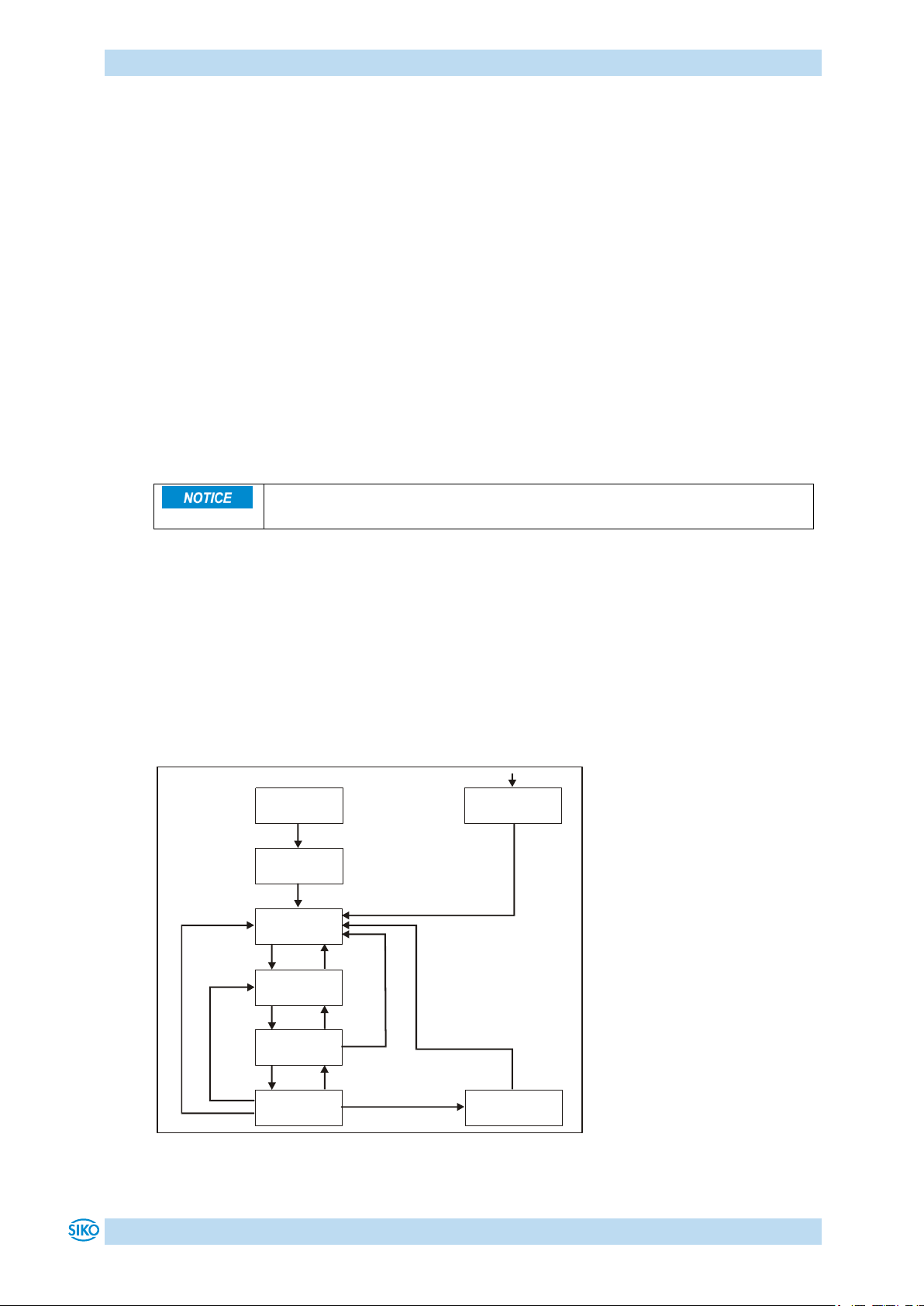
Communication via CAN bus
Start
Not Ready to
Switch On
Switch On
Disabled
Ready to
Switch On
Switched On
Operation
Enable
Fault
Quick Stop
Active
1
0
7
2
6
3
4
5
10 12
8
9
14
13
11
The node-guard protocol is only enabled when the heartbeat protocol is
deactivated!
Toggle Bit:
The toggle bit must alternate between two subsequent responses of the actuator.
The value of the toggle bit with the first response of the actuator is 0 after activation of the
guarding protocol.
Status:
Status = 0: 'INITIALISATION'
Status = 4: 'STOPPED'
Status = 5: 'OPERATIONAL'
Status = 127: 'PRE-OPERATIONAL'
The identifier of the heartbeat protocol is permanently set to 1792 + Node-ID and cannot be
changed.
A node guard telegram can be sent in the NMT statuses 'OPERATIONAL', 'PRE-OPERATIONAL' or
'STOPPED'.
9.4 State Machine
In the status word, the CANopen state machine indicates operational and error states of the
drive resulting from operational transitions.
The states of the state machine can change via control word (see chapter 9.6: Control word)
or due to internal events (e. g., occurrence of a fault).
The current state of the state machine can be read via the status word (see chapter 9.5:
Status word).
AG06
Fig. 10: State machine
Date: 07.02.2018 Art. No. 85674 Mod. status 055/18 Page 50 of 114
Page 51

Communication via CAN bus
The following states of the state machine of the actuator are available:
'NOT READY TO SWITCH ON'
The actuator is being initialized after switching on. No travel commands can be accepted.
Motor is enabled.
'SWITCH ON DISABLED'
Initialization completed. No travel commands can be accepted. Motor is enabled.
'READY TO SWITCH ON'
No travel commands can be accepted. Motor is enabled.
'SWITCHED ON'
No travel commands can be accepted. Motor is enabled.
'OPERATION ENABLED'
Travel commands can be accepted. Motor is in control state.
'QUICK STOP ACTIVE'
The Quick Stop command was executed. Motor decelerates with maximum deceleration and
stops with stop torque. Current positioning is cancelled. No travel commands can be
accepted.
'FAULT'
An error has occurred. Motor is enabled. Current positioning is cancelled. No travel
commands can be accepted.
The states of the State Machine can be changed via internal events or through commands of
the master via control word (see chapter 9.6: Control word).
State change 0: START NOT READY TO SWITCH ON
Power on or software reset of the actuator.
State change 1: NOT READY TO SWITCH ON SWITCH ON DISABLED
Initialization and self-test of the actuator successfully completed.
State change 2: SWITCH ON DISABLED READY TO SWITCH ON
'Shutdown' command by master.
State change 3: READY TO SWITCH ON SWITCHED ON
'Switch On' command by master.
State change 4: SWITCHED ON OPERATION ENABLE
'Enable Operation' command by master.
State change 5: OPERATION ENABLE SWITCHED ON
'Disable Operation' command by master.
State change 6: SWITCHED ON READY TO SWITCH ON
'Shutdown' command by master.
State change 7: READY TO SWITCH ON SWITCH ON DISABLED
'Disable Voltage' command by master.
State change 8: OPERATION ENABLE READY TO SWITCH ON
'Shutdown' command by master.
State change 9: OPERATION ENABLE SWITCH ON DISABLED
'Disable Voltage' command by master.
State change 10: SWITCHED ON SWITCH ON DISABLED
'Disable Voltage' command by master.
AG06
Date: 07.02.2018 Art. No. 85674 Mod. status 055/18 Page 51 of 114
Page 52
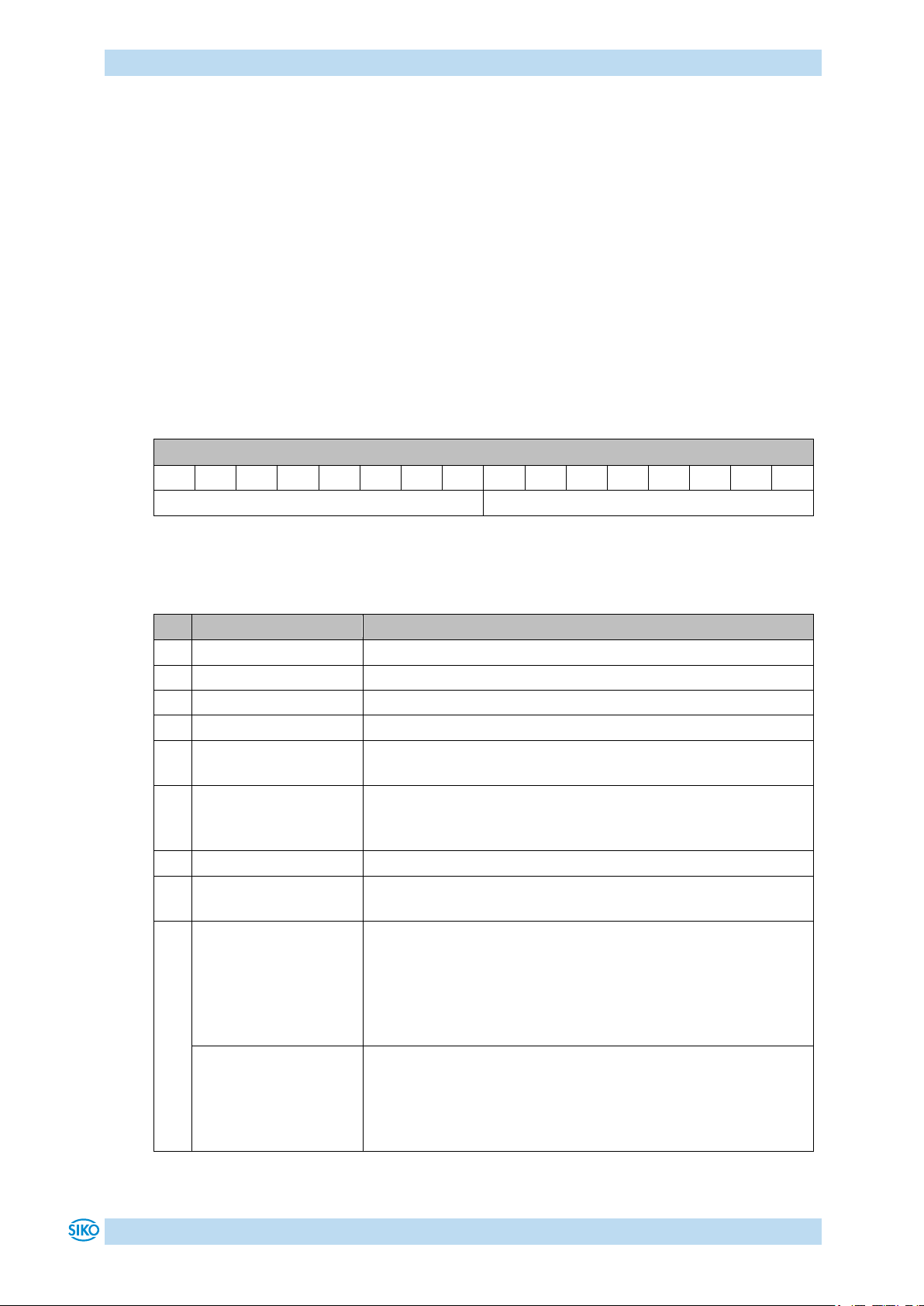
Communication via CAN bus
Status word
15
14
13
12
11
10 9 8 7 6 5 4 3 2 1 0
MSB High Byte
Low Byte LSB
Bit
Designation
Description
0
Ready to switch on
indicates the state of the State Machine (see Table 32)
1
Switched on
indicates the state of the State Machine (see Table 32)
2
Operation enabled
indicates the state of the State Machine (see Table 32)
3
Fault
indicates the state of the State Machine (see Table 32)
4
Voltage enabled
Bit 4 is set when the supply voltage is within the tolerance
limit.
5
Quick stop
indicates the state of the State Machine (see Table 32)
Bit 5 is set when the actuator is not in the 'QUICK STOP
ACTIVE' state.
6
Switch on disabled
indicates the state of the State Machine (see Table 32)
7
Warning
Bit 7 is set when a warning is active (see chapter 7.1:
Warnings).
8
Profile Position Mode:
show readiness for
travel
Bit 8 is set if the State Machine is in the 'OPERATION ENABLED'
state und the follwing conditions are met:
- no fault present
- Supply voltage of the output stage is applied
- no limit have been exceeded
- no active travel job
Profile Velocity Mode:
show readiness for
travel
Bit 8 is set if the State Machine is in the 'OPERATION ENABLED'
state und the follwing conditions are met:
- no fault present
- no active travel job
- Supply voltage of the output stage is applied
State change 11: OPERATION ENABLE QUICK STOP ACTIVE
'Quick Stop' Befehl vom Master
State change 12: QUICK STOP ACTIVE SWITCH ON DISABLED
'Disable Voltage' command by master.
State change 13: All states FAULT
A fault has occurred.
State change 14: FAULT SWITCH ON DISABLED
'Fault Reset' command by master.
9.5 Status word
The status word reflects the current status of the actuator. It consists of 16 bits and is
mapped on object 6041h and on the 3 Transmit PDOs.
Table 30: Status word
The following table lists the designations of the individual bits of the status word and their
meanings.
AG06
Date: 07.02.2018 Art. No. 85674 Mod. status 055/18 Page 52 of 114
Page 53

Communication via CAN bus
Bit
Designation
Description
9
Remote
Bit 9 is set when the actuator is in the NMT status
'OPERATIONAL' or 'STOPPED'. The actuator receives commands
via CAN interface in this case.
10
Profile Position Mode:
Target reached
Bit 10 is set when the drive has come to a stop at the predefined target position within the defined window after a
successfully executed positioning command.
Profile Velocity Mode:
Target reached
Bit 10 is set when the actual speed is within the defined
window of the target speed.
11
internal Limit
Bit 11 is set when the upper or lower limits have been
exceeded.
12
Profile Position Mode:
Set Point
Acknowledged
Bit 12 is set when the drive controller has started a travel
command in the positioning mode.
A travel job is started via bit 'New Setpoint' in the control word
(object 6040h: control word bit 4) (value 0 1).
Subsequently, the controller firmware plausibilizes the target
position, the operation and control parameters and the local
state of the drive and sets bit 12 after the check has been
passed successfully.
Bit 12 is deleted when bit 4 in the control word has been reset
to zero following a positioning job (Clear new setpoint).
Profile Velocity Mode:
Speed
Bit 12 is set when the drive stands still.
13
reserved
statically on 0
14
Profile Position Mode:
Pos active
Bit 14 is set when there is an active positioning job in the
operation mode 'Profile Position Mode' (positioning mode).
Notice! No new setpoint is accepted and travelling in inching
operation is disabled as long as bit 14 is set!
Profile Velocity Mode
no meaning, statically on 0
15
Profile Position Mode:
drive travels
The drive shaft of the actuator is moving if bit 15 is set.
Profile Velocity Mode
statically on 0
State
Bit 7
Bit 6
Bit 5
Bit 4
Bit 3
Bit 2
Bit 1
Bit 0
Not Ready to Switch On
x 0 x x 0 0 0 0 Switch On Disabled
x 1 x x 0 0 0
0
Ready to Switch On
x 0 1 x 0 0 0 1 Switched On
x 0 1 x 0 0 1 1 Operation Enabled
x 0 1 x 0 1 1 1 Quick Stop Activ
x 0 0 x 0 1 1 1 Fault
x 0 x x 1 0 0
0
Table 31: Bit description of the status word
The following table represents the possible states of the state machine and the resulting bit
values.
The field containing an x are irrelevant for the states of the state machine.
Table 32: Low byte status word States of the state machine
AG06
Date: 07.02.2018 Art. No. 85674 Mod. status 055/18 Page 53 of 114
Page 54
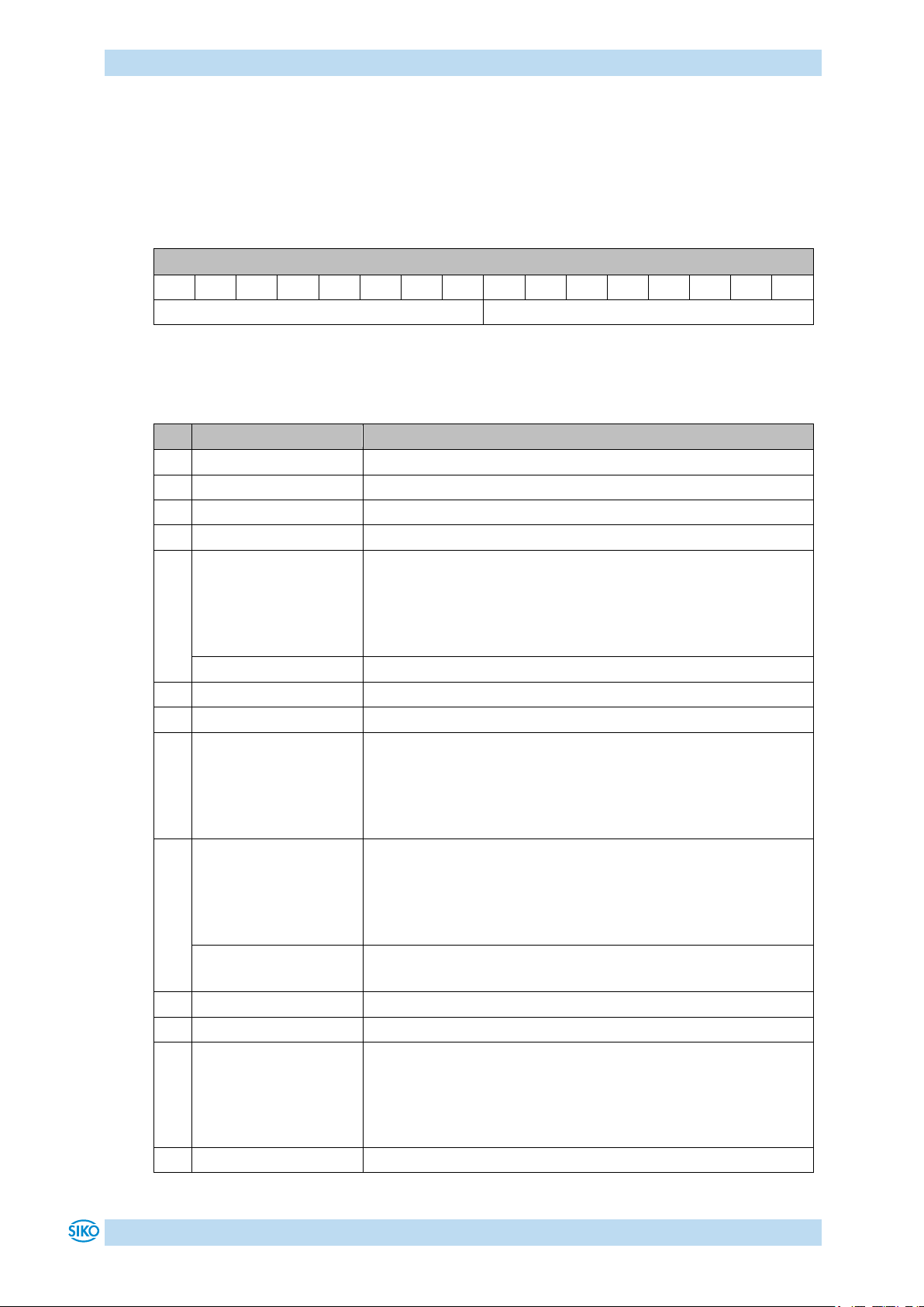
Communication via CAN bus
Control word
15
14
13
12
11
10 9 8 7 6 5 4 3 2 1 0
MSB High Byte
Low Byte LSB
Bit
Designation
Description
0
Switch on
controls the state of the State Machine (see Table 35)
1
Disable voltage
controls the state of the State Machine (see Table 35)
2
Quick stop
controls the state of the State Machine (see Table 35)
3
Enable operation
controls the state of the State Machine (see Table 35)
4
Profile Position Mode:
New Setpoint
By bit 4, positioning is triggered in the drive controller in the
OPERATION ENABLED state (value 0 1).
The drive controller acknowledges the travel command via bit
12 'Setpoint acknowledged' in the status word (see chapter
9.5: Status word).
Profile Velocity Mode
no meaning
5
reserved
6 reserved
7
Fault reset
If the state machine of the actuator is in the FAULT state, the
fault is reset by an edge on bit 7 (0 1) and the state
machine is set to the SWITCH ON DISABLED state on the
condition that the cause of the fault has been resolved in
advance (see chapter 7.2: Errors).
8
Profile Position Mode:
Stop
By setting bit 8 on value 1, interruption of travel can be
triggered during a running positioning event. Motor runs out
with programmed deceleration and stops in the control state.
Positioning is resumed and completed after resetting the bit
(value 1 0).
Profile Velocity Mode:
Stop
By bit 8, drive movement is triggered in the velocity mode in
the OPERATION ENABLED state (value 1 0).
9
reserved
10
reserved
11
Key enable
Key enable can be controlled via Bit 11 in the OPERATION
ENABLED state:
0 = Key enable as defined by object 2400h sub-index 08h
1 = Key enable inverted as defined by object 2400h sub-index
08h
12
reserved
9.6 Control word
The control word consists of 16 bits and is mapped on the object 6040h, and in the 3 Receive
PDOs.
It contains bits for controlling the state machine as well as controlling the operational
modes, Profile Position Mode (positioning mode) and Profile Velocity Mode (velocity mode).
Table 33: Control word
The following table lists the designations of the individual bits of the control word and their
meanings.
AG06
Date: 07.02.2018 Art. No. 85674 Mod. status 055/18 Page 54 of 114
Page 55
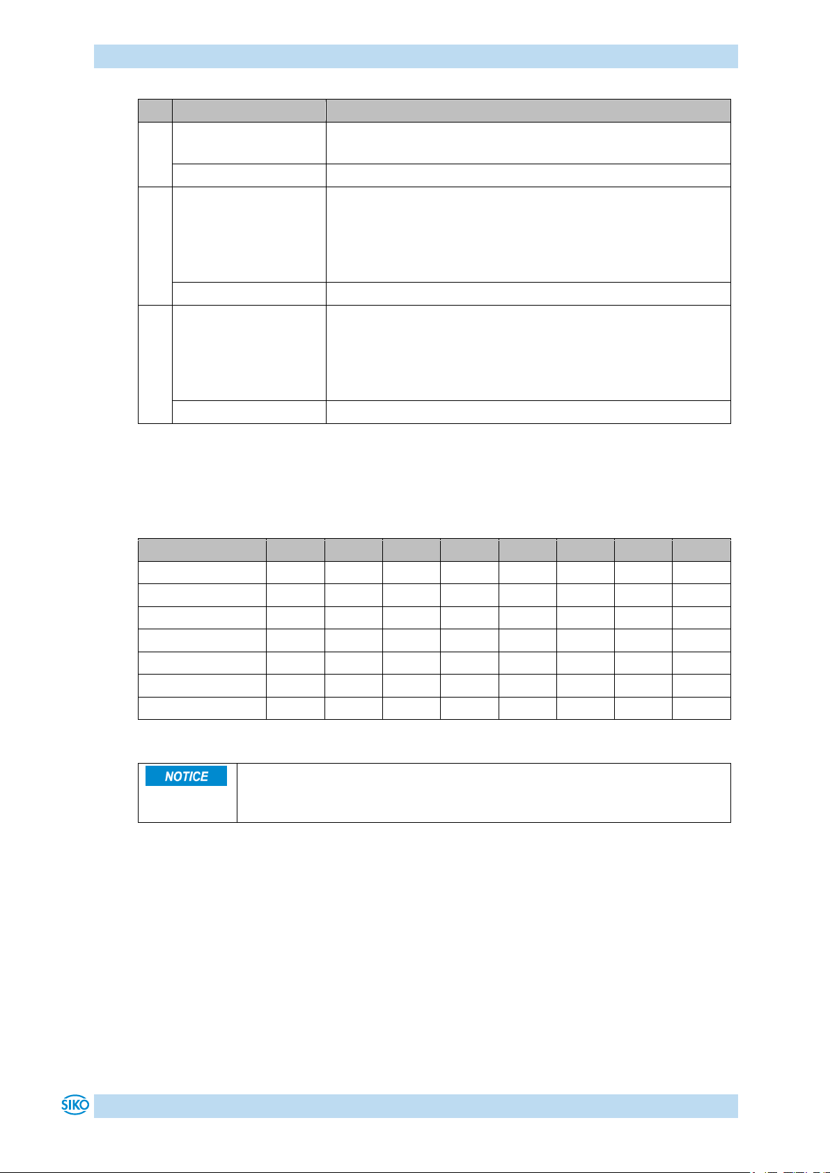
Communication via CAN bus
Bit
Designation
Description
13
Profile Position Mode:
Inching operation 1
Inching operation 1 is started by an edge change (value 0
1) on bit 13 (see chapter 4.1.3.2: Inching operation).
Profile Velocity Mode
no meaning
14
Profile Position Mode:
Inching operation 2
positive
Inching operation 2 is started in positive travel direction by an
edge change (value 0 1) on bit 14 (see chapter 4.1.3.2:
Inching operation).
The drive travels in positive direction until bit 14 has been
deleted.
Profile Velocity Mode
no meaning
15
Profile Position Mode:
Inching operation 2
negative
Inching operation 2 is started in negative travel direction by
an edge change (value 0 1) on bit 15 (see chapter 4.1.3.2:
Inching operation).
The drive travels in negative direction until bit 15 has been
deleted.
Profile Velocity Mode
no meaning
Command
Bit 7
Bit 6
Bit 5
Bit 4
Bit 3
Bit 2
Bit 1
Bit 0
Shutdown
0 x x x x 1 1 0 Switch On
0 x x x 0 1 1 1 Disable Voltage
0 x x x x x 0 x Quick Stop
0 x x x x 0 1 x Disable Operation
0 x x x 0 1 1 1 Enable Operation
0 x x x 1 1 1 1 Fault Reset
0 1
x x x x x x x
PDOs are anabled in the NMT status Operational only.
Travel commands are enabled in the Operation Enabled state of the state
machine.
Table 34: Bit description of the control word
The following table shows the control of the state machine with the bit combinations of the
control word required.
The fields containing an x are irrelevant for the control of the state machine.
Table 35: Low Byte Control word
AG06
Date: 07.02.2018 Art. No. 85674 Mod. status 055/18 Page 55 of 114
Page 56
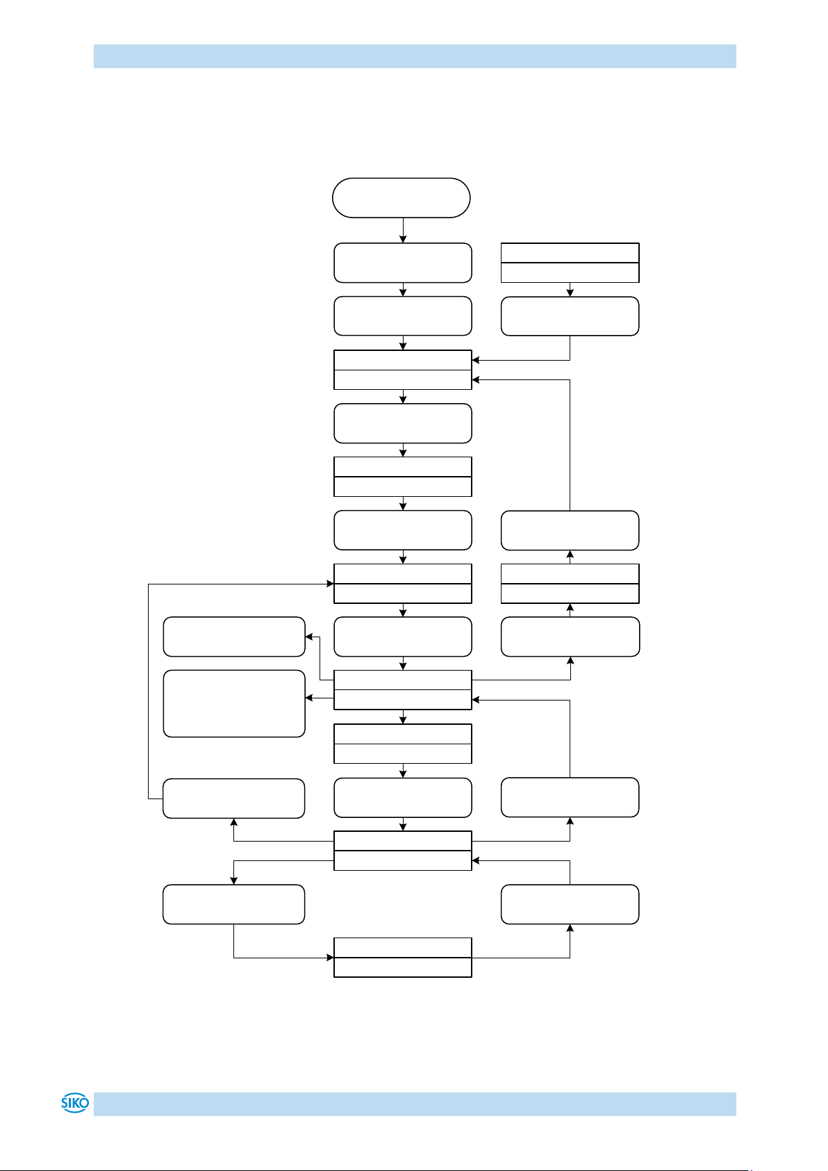
Communication via CAN bus
Positioning activ
SW = 110x 0x10 0011 0111
Enter Operational
(NMT)
Switch on disabled
SW = xxxx xxxx x1x1 0000
Operating voltage On
“Shutdown“- command
CW = 0000 0001 0000 0110
“Switch on“- command
CW = 0000 0001 0000 0111
“Enable
operation“command
CW = 0000 0001 0000 1111
Start travel job
CW = 0000 0000 000↑ 1111
Ready to switch on
SW = xxxx xxxx x01x 0001
Switched on
SW = xxxx xxxx x01x 0011
Operation enabled
SW = xxxx xxxx x01x 0111
Drive ready to travel
SW = 0000 0x11 0011 0111
Intermediate stop active
SW = 010x 0x10 0011 0111
Intermediate stop
CW = 0000 0001 000x 1111
Continue positioning
CW = 0000 0000 000x 1111
Cancel positioning job
CW = 0000 0000 0000 0111
Positioning job completed
“Fault reset“- command
CW. 7 = ↑
“Quick-stop“- command
CW = 0000 0000 0000 0010
“Disable Voltage“ command
CW = 0000 0000 0000 0000
Quick stop active
SW = xxxx xxxx x00x 0111
Start Inching 1
CW = 00↑0 0000 0000 1111
Start Inching 2
CW = 0↑00 0000 0000 1111
oder
CW = ↑000 0000 0000 1111
Fault
SW = xxxx xxxx x0xx 1000
SW = Statusword
CW = Controlword
↑ Means change from
0 to 1
X Bit may be 0 or 1
START
9.7 Flowchart of the Profile Position Mode (positioning mode)
Fig. 11: Flowchart of the Profile Position Mode (positioning mode)
AG06
Date: 07.02.2018 Art. No. 85674 Mod. status 055/18 Page 56 of 114
Page 57
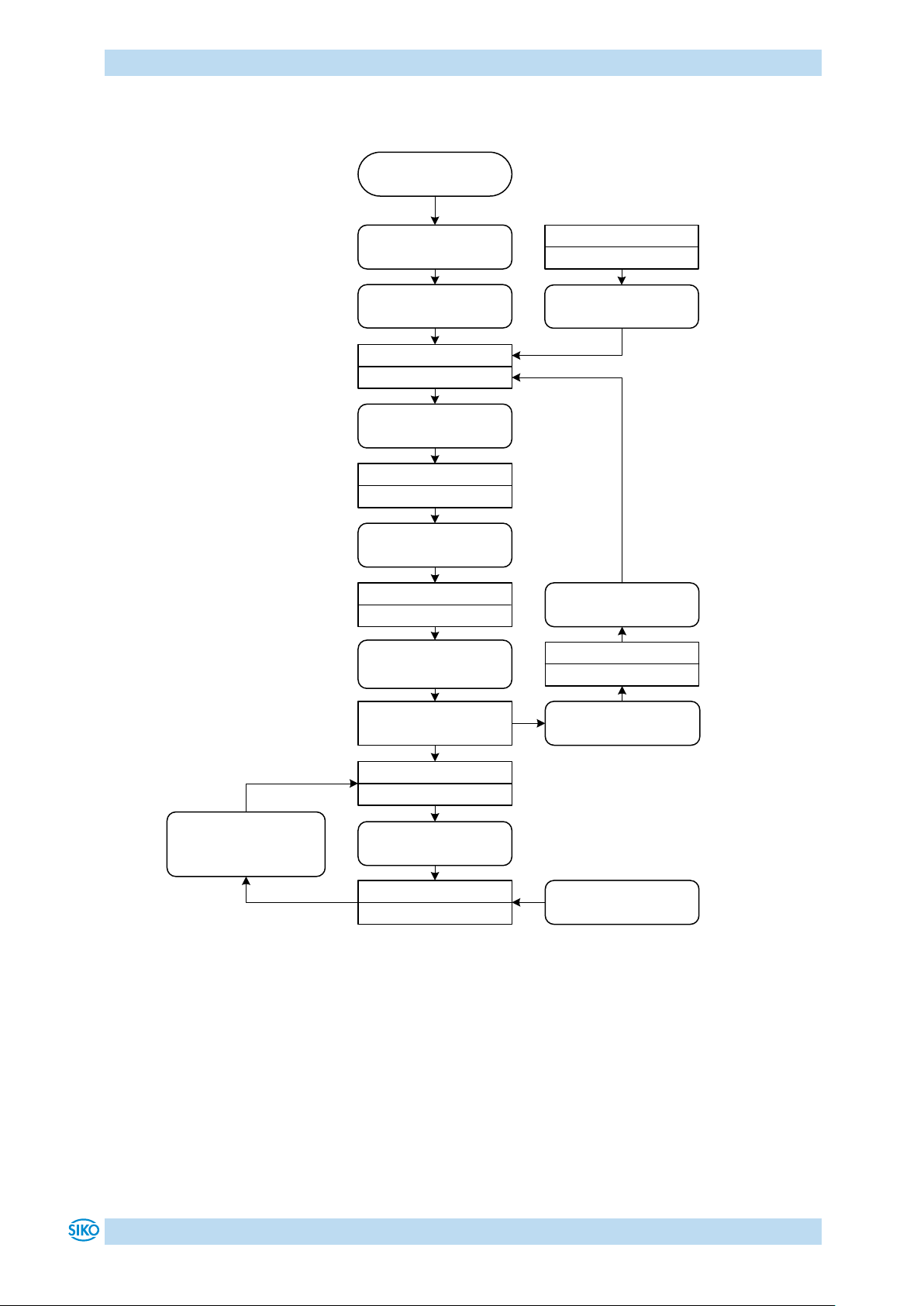
Communication via CAN bus
SW = Statusword
CW = Controlword
↓ Means change from
1 tot 0
↑ Means change from
0 to 1
X Bit may be 0 or 1
Enter Operational
(NMT)
Switch on disabled
SW = xxxx xxxx x1x1 0000
Operating voltage On
“Shutdown“- command
CW = 0000 0001 0000 0110
“Switch on“- command
CW = 0000 0001 0000 0111
“Enable operation“ -
command
CW = 0000 0001 0000 1111
Start Velocity Mode
CW = 000 0000 0000 1111
Ready to switch on
SW = xxxx xxxx x01x 0001
Switched on
SW = xxxx xxxx x01x 0011
Operation enabled
SW = xxxx xxxx x01x 0111
Drive raedy to travel
SW = 0001 0x11 0011 0111
Stop Velocity Mode
CW = 0000 0001 0000 1111
or Setpoint = 0
“Fault reset“- command
CW. 7 = ↑
“Quick-stop“- command
CW = 0000 0000 0000 0010
“Disable Voltage“ command
CW = 0000 0000 0000 0000
Quick stop active
SW = xxxx xxxx x00x 0111
Fault
SW = xxxx xxxx x0xx 1000
Change target value
CW = 0000 0000 0000 1111
Velocity Mode activ
SW = 0000 0x10 0011 0111
START
9.8 Flowchart of the Profile Velocity Mode operation mode (velocity mode)
Fig. 12: Flowchart of the Profile Velocity Mode (velocity mode)
AG06
Date: 07.02.2018 Art. No. 85674 Mod. status 055/18 Page 57 of 114
Page 58
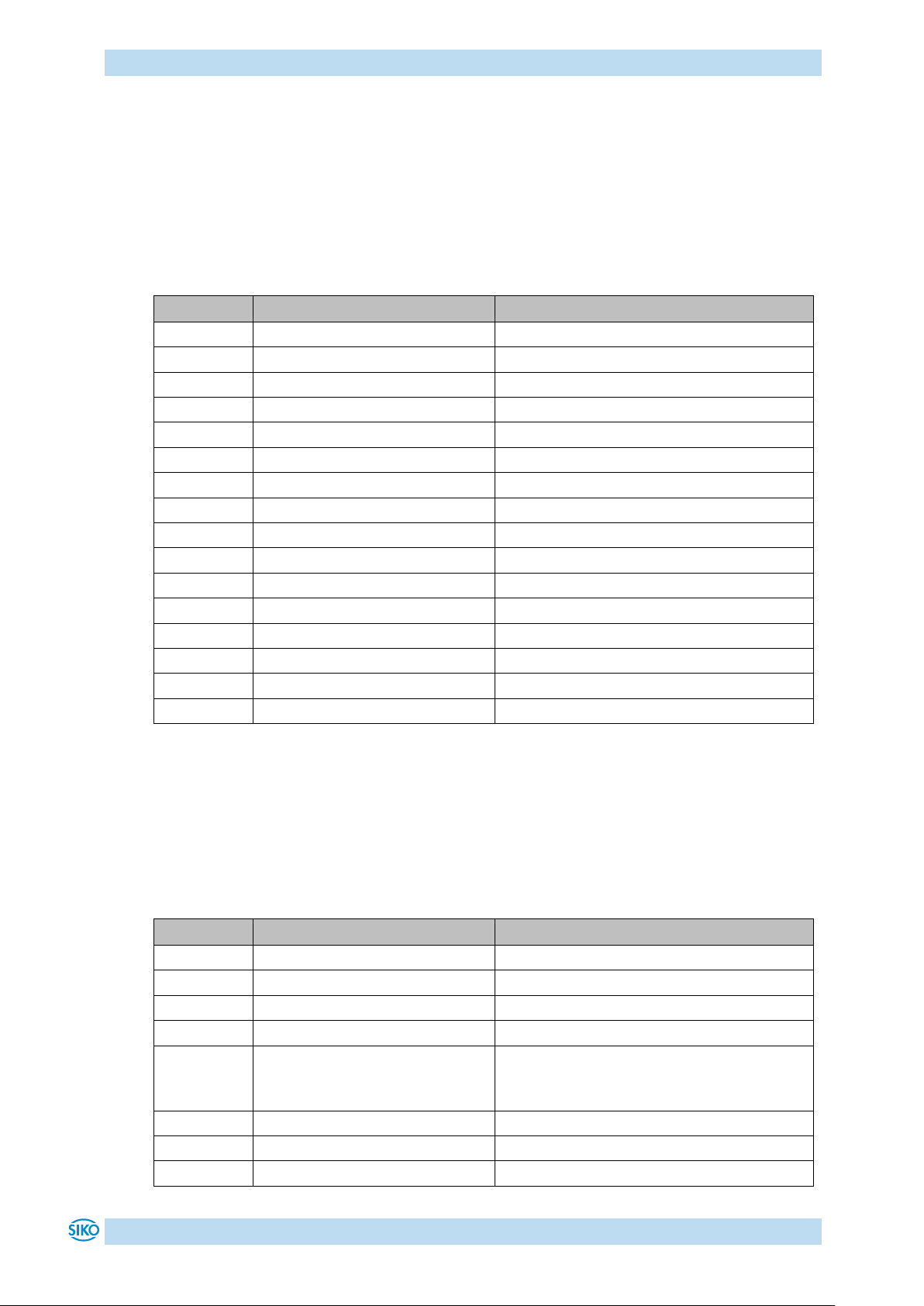
Communication via CAN bus
Identifier
Message
Meaning
0x000
0x01 0x05
NMT: Enter OPERATIONAL
0x205
0x06 0x01
RPDO1: Shutdown command
0x205
0x07 0x01
RPDO1: Switch On command
0x205
0x0F 0x01
RPDO1: Enable Operation command
0x405
0x1F 0x00 0x88 0x13 0x00 0x00
RPDO3: Travel to position +5000
- - wait until target position has been reached
0x205
0x0F 0x01
RPDO1: clear New Setpoint
0x405
0x1F 0x00 0x78 0xEC 0xFF 0xFF
RPDO3: Travel to position -5000
0x205
0x1F 0x01
RPDO1: Intermediate stop
0x205
0x1F 0x00
RPDO1: continue positioning
- - wait until target position has been reached
0x205
0x0F 0x01
RPDO1: clear New Setpoint
0x205
0x07 0x01
RPDO1: Disable Operation command
0x205
0x06 0x01
RPDO1: Shutdown command
0x205
0x00 0x01
RPDO1: Disable Voltage command
0x000
0x80 0x05
NMT: Enter PRE-OPERATIONAL
Identifier
Message
Meaning
0x000
0x01 0x05
NMT: Enter OPERATIONAL
0x205
0x06 0x01
RPDO1: Shutdown command
0x205
0x07 0x01
RPDO1: Switch On command
0x205
0x0F 0x01
RPDO1: Enable Operation command
0x505
0x0F 0x00 0x0A 0x00 0x00 0x00
RPDO4: Start of velocity mode with the
target speed of +10 rev/min positive sense
of rotation
- - wait until target speed has been reached
0x505
0x0F 0x00 0x05 0x00 0x00 0x00
RPDO4: Change of velocity to +5 rev/min
0x205
0x0F 0x01
RPDO1: Stop drive movement
9.9 Examples
9.9.1 Example of the Profile Position Mode (positioning mode)
In the following table a positioning example in the Profile Position Mode (positioning mode)
is represented.
The node address of the actuator is 5 in this example.
Table 36: Positioning example in Profile Position Mode
9.9.2 Example of the Profile Velocity Mode (velocity mode)
In the following table an example in the Profile Velocity Mode (velocity mode) is represented.
The node address of the actuator is 5 in this example. Operating mode change via parameter
20, see chapter 8: Parameter description (Default: Profile Position Mode).
AG06
Date: 07.02.2018 Art. No. 85674 Mod. status 055/18 Page 58 of 114
Page 59
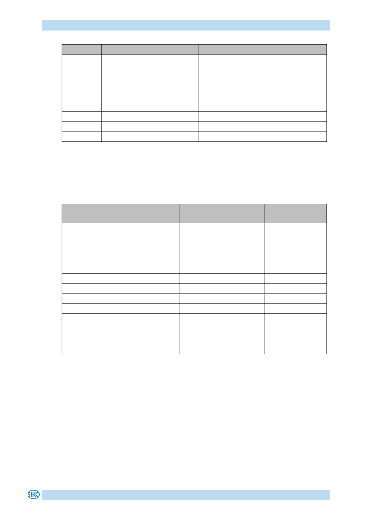
Communication via CAN bus
Identifier
Message
Meaning
0x505
0x0F 0x00 0xF8 0xFF 0xFF 0xFF
RPDO4: Start of velocity mode with the
target speed of -8 rev/min (negative sense
of rotation)
- - wait until target speed has been reached
0x205
0x0F 0x01
RPDO1: Stop drive movement
0x205
0x07 0x01
RPDO1: Disable Operation command
0x205
0x06 0x01
RPDO1: Shutdown command
0x205
0x00 0x01
RPDO1: Disable Voltage command
0x000
0x80 0x05
NMT: Enter PRE-OPERATIONAL
Default identifier
(hexadecimal)
Default identifier
(decimal)
Description
Own setting
0 0 Network management (NMT)
80
128
SYNC – Message
80 + Node-ID
128 + Node-ID
Emergency Message
180 + Node-ID
384 + Node-ID
TPDO1
200 +Node-ID
512 + Node-ID
RPDO1
380 + Node-ID
896 + Node-ID
TPDO3
400 + Node-ID
1024 + Node-ID
RPDO3
480 + Node-ID
1152 + Node-ID
TPDO4
500 + Node-ID
1280 + Node-ID
RPDO4
580 + Node-ID
1408 + Node-ID
SDO (tx)
600 + Node-ID
1536 + Node-ID
SDO (rx)
700 + Node-ID
1792 + Node-ID
Heartbeat Message
700 + Node-ID
1792 + Node-ID
Node-Guard Message
Table 37: Example of Profile Velocity Mode
9.10 Overview of CANopen identifiers
The following table offers an overview of the identifiers used in the actuator:
Table 38: Overview of identifiers
9.11 Setting the CAN baud rate
The CAN baud rate is entered via Object 2100h (CAN baud rate).
The baud rate is factory-set to 500 kbit/s.
AG06
Date: 07.02.2018 Art. No. 85674 Mod. status 055/18 Page 59 of 114
Page 60

Communication via CAN bus
Index
Name
Description
see
page
1000h
Device type
The object indicates the device profile number of the
actuator.
63
1001h
Error register
The object shows error states of the actuator.
64
1002h
Manufacturer
Status Register
Contains the system status word of the actuator (see
chapter 9.2: System Status Word).
64
1003h
Pre-Defined Error
Field
The object stores up to 10 error messages.
65
1005h
COB-ID Sync
Message
Setting of the COB ID of the SYNC object.
65
1008h
Manufacturer
Device Name
Indicates the device name.
66
100Ah
Manufacturer
Software Version
Indicates the software version of the controller
firmware.
66
100Ch
Guard Time
Setting of the 'Guard Time' for the Node Guarding
protocol (see chapter 9.3.11: Node Guarding).
67
100Dh
Life Time Factor
Setting of the time interval 'Life Time' (see chapter
9.3.11: Node Guarding).
67
1011h
Restore Default
Parameters
Restoration of factory-set states of the changeable
parameters and calibration of the actuator (see chapter
5: Calibration).
67
1014h
COB-ID Emergency
Message
Setting of the COB ID of the Emergency object.
69
9.12 EDS file
The EDS files (electronic data sheet) are available for the actuator.
This file enables easy integration and configuration of the actuator in a CANopen network
using commercial CANopen configurations.
9.13 Directory of objects
Every CANopen device keeps a directory of objects where all parameters of the device are
deposited in the form of object entries. The object entries can be accessed via SDO
communication services (see chapter 9.3.7: Service Data Objects (SDOs)). Thus, a parameter
can be read (SDO upload) and written (SDO download) if permitted by the object entry access
rights or the state of the device, respectively.
The following index ranges are used:
1000h - 1FFFh objects of the communication profile CIA DS-301 V4.0.
2000h - 5FFFh manufacturer-specific object entries.
6000h - 9FFFh objects of the device profile CIA DSP-402 V2.0.
9.13.1 Overview of objects
The following table offers an overview of the objects of the actuator.
AG06
Date: 07.02.2018 Art. No. 85674 Mod. status 055/18 Page 60 of 114
Page 61

Communication via CAN bus
Index
Name
Description
see
page
1017h
Producer
Heartbeat Time
Setting of the cycle time for the heartbeat protocol (see
chapter 9.3.10: Heartbeat protocol).
70
1018h
Identity Objekt
Contains the Vendor ID of the device manufacturer.
70
1200h
Server SDO
Parameter
Contains the COB IDs of the default server SDO.
72
1400h
1st Receive PDO
Parameter
Setting of the communication parameters of the RPDO1.
73
1401h
2nd Receive PDO
Parameter
Compatibility entry
75
1402h
3rd Receive PDO
Parameter
Setting of the communication parameters of the RPDO3.
76
1403h
4th Receive PDO
Parameter
Setting of the communication parameters of the RPDO4.
78
1600h
1st Receive PDO
Mapping
Parameter
Contains the objects mapped on the RPDO1 (see chapter
9.3.6.1: 1st Receive PDO (RPDO1)).
80
1601h
2nd Receive PDO
Mapping
Parameter
Compatibility entry
80
1602h
3rd Receive PDO
Mapping
Parameter
Contains the objects mapped on the RPDO3 (see chapter
9.3.6.2: 3rd Receive PDO (RPDO3)).
81
1603h
4th Receive PDO
Mapping
Parameter
Contains the objects mapped on the RPDO4 (see chapter
9.3.6.3: 4th Receive PDO (RPDO4)).
82
1800h
1st Transmit PDO
Parameter
Setting of the communication parameters of the TPDO1.
83
1801h
2nd Transmit PDO
Parameter
Compatibility entry
85
1802h
3rd Transmit PDO
Parameter
Setting of the communication parameters of the TPDO3.
86
1803h
4th Transmit PDO
Parameter
Setting of the communication parameters of the TPDO4.
88
1A00h
1st Transmit PDO
Mapping
Parameter
Contains the objects mapped on the TPDO1 (see chapter
9.3.5.1: 1st Transmit PDO (TPDO1)).
91
1A01h
2nd Transmit PDO
Mapping
Parameter
Compatibility entry
91
1A02h
3rd Transmit PDO
Mapping
Parameter
Contains the objects mapped on the TPDO3 (see chapter
9.3.5.2: 3rd Transmit PDO (TPDO3)).
92
1A03h
4th Transmit PDO
Mapping
Parameter
Contains the objects mapped on the TPDO4 (see chapter
9.3.5.3: 4th Transmit PDO (TPDO4)).
93
AG06
Date: 07.02.2018 Art. No. 85674 Mod. status 055/18 Page 61 of 114
Page 62
Communication via CAN bus
Index
Name
Description
see
page
2001h
Manufacturer
Offset
Manufacturer-specific offset value (is added internally to
the position value).
94
2100h
Can-Baud rate
Setting of the CAN baud rate.
94
2101h
Node-ID
Setting of the node address.
95
2102h
Transfer reduction
Contains the gear reduction.
95
2400h
Display and
Operation
Parameter Set
Configuration of display and operation.
95
2410h
Motor Parameter
Set
Setting of the control parameters of the drive controller.
99
2412h
Spindle Pitch
Setting of the spindle pitch.
102
2413h
Pos Type
Setting of the positioning type.
102
2415h
Delta Jog
Setting of the travel distance in inching operation 1.
103
2416h
Stop Mode Inching
Mode 2
Setting of the stop behaviour in inching operation 2.
103
2417h
Inpos Mode
Setting of the behaviour upon reaching the positioning
window.
103
2418h
Loop Length
Setting the loop length.
104
2419h
Contouring Error
Limit
Setting the contouring error limit.
104
241Ah
Contouring Error
Current contouring error
104
241Bh
Power Supply
Voltage
Voltage supply of output stage and control.
105
241Ch
Output Stage
Temperature
Output stage temperature.
105
241Eh
Motor Current
Actual motor current
106
2421h
Motor Current
Limit
Setting of motor current limitation.
106
2423h
Battery Voltage
Actual battery voltage
106
2450h
Inching 2 Offset
Offset value in inching operation 2.
107
2451h
Type of
acceleration
Inching Mode 2
Type of acceleration in inching operation 2.
107
2500h
Production Date
Contains the drive's production date.
107
2501h
Display Software
Version
Indicates the software version oft he display controller
firmware.
108
6040h
Controlword
Contains the control word of the state machine for
drives.
108
6041h
Statusword
Contains the status word of the state machine for drives.
109
6060h
Modes of
Operation
Setting of the operation mode: Profile Position Mode /
Profile Velocity Mode.
109
6061h
Modes of
Operation Display
Operating mode set.
110
AG06
Date: 07.02.2018 Art. No. 85674 Mod. status 055/18 Page 62 of 114
Page 63
Communication via CAN bus
Index
Name
Description
see
page
6064h
Position Actual
Value
Contains the absolute actual position in the operation
mode Profile Position Mode (positioning mode).
110
6067h
Position Window
Setting of the tolerance window.
111
606Ch
Velocity Actual
Value
Contains the actual velocity in the operation mode
Profile Velocity Mode (velocity mode).
111
607Ah
Target Position
Contains the target position in the operation mode
Profile Position Mode (positioning mode).
111
607Ch
Calibration Value
Calibration
112
607Dh
Software Position
Limit
Setting of the limits.
112
607Eh
Polarity
Setting of the polarity.
113
6091h
Gear Ratio
Setting of gear ratio.
113
60FFh
Target Velocity
Contains the target velocity in the operation mode
Profile Velocity Mode (velocity mode).
114
Sub-index
00h
Description
Information on the device profile
Access
read-only
PDO mapping
no
Data type
Unsigned32
Default
00000192h
EEPROM
no
Bit 31 - 24
Manufacturer-specific (not used)
Bit 23 - 16
drive type (not used)
Bit 15 - 0
device profile number
Table 39: Overview of objects
9.13.2 Description of objects
Below, all objects of the actuator are described sorted by their indexes.
9.13.2.1 1000
: Device Type
h
Object 1000h indicates the device profile number.
Format description:
AG06
Date: 07.02.2018 Art. No. 85674 Mod. status 055/18 Page 63 of 114
Page 64
Communication via CAN bus
Sub-index
00h
Description
current error code
Access
read-only
PDO mapping
no
Data type
Unsigned8
Default
no
EEPROM
no
Bit 7
Manufacturer-specific error
Bit 6
reserved (statically 0)
Bit 5
Drive shaft blocked
Bit 4
Error during data transfer
Bit 3
Temperature
Bit 2
Voltage
Bit 1
Current
Bit 0
General error (is set when error is present)
Sub-index
00h
Description
Manufacturer-specific status register
Access
read-only
PDO mapping
no
Data type
Unsigned32
Default
no
EEPROM
no
Bit 31 - 16
not used
Bit 15 - 0
see chapter 9.2: System Status Word
9.13.2.2 1001
Object 1001h indicates the error state of the device.
Format description:
: Error Register
h
A detailed error evaluation can be attained via object 1003h (Predefined Error Field). Faults
and errors are signalled at the time of their occurrence by an emergency message (see chapter
9.3.9: Emergency Object (EMCY)).
9.13.2.3 1002
Object 1002h indicates the system status word of the actuator (see chapter 9.2: System Status
Word).
Format description:
: Manufacturer Status Register
h
AG06
Date: 07.02.2018 Art. No. 85674 Mod. status 055/18 Page 64 of 114
Page 65
Communication via CAN bus
Sub-index
00h
Description
number of fault messages
Access
read-write (recordable in the "Pre-Operational" and "Operational" states,
cannot be written with active travel job)
PDO mapping
no
Data type
Unsigned8
Default
0
EEPROM
no
Value range
0 ... 10
Sub-index
01h ... 0Ah
Description
faults that occurred
Access
read-only
PDO mapping
no
Data type
Unsigned32
Default
no
EEPROM
yes
Bit 31 - 16
not used
Bit 15 - 8
error code high byte (see chapter 9.3.9.1: Error Code)
Bit 7 - 0
error code low byte (see chapter 9.3.9.1: Error Code)
Sub-index
00h
Description
COB-ID SYNC message (recordable in the "Pre-Operational" state)
Access
read-write
PDO mapping
no
Data type
Unsigned32
Default
80h
EEPROM
no
9.13.2.4 1003
Object 1003h stores the last 10 causes of faults.
The entry under sub-index 00h contains the number of faults currently stored.
The latest fault message is stored under sub-index 01h.
Writing a '0' on sub-index 00h resets the fault buffer.
: Pre-defined Error Field
h
Format description:
9.13.2.5 1005
The COB-ID of the SYNC object is set via object 1005h.
The SYNC message is sent to all network participants (broadcast object).
: COB-ID Sync Message
h
AG06
Date: 07.02.2018 Art. No. 85674 Mod. status 055/18 Page 65 of 114
Page 66
Communication via CAN bus
Bit 31 - 30
not used
Bit 29
0 = 11-bit identifier (CAN 2.0A)
1 = 29-bit identifier (CAN 2.0B)
Bit 28 - 11
if bit 29=1, Bit 28 ... 11 des 29-bit identifier
Bit 10 - 0
bit 10 ... 0 of the identifier
Sub-index
00h
Description
Device name in ASCII characters
Access
const
PDO mapping
no
Data type
Visible String
Default
no
EEPROM
no
Bit 7 - 0
41h = ' A ' (ASCII character, ISO 8859)
Bit 15 - 8
47h = ' G ' (ASCII character, ISO 8859)
Bit 23 - 16
30h = ' 0 ' (ASCII character, ISO 8859)
Bit 31 - 24
36h = ' 6 ' (ASCII character, ISO 8859)
Sub-index
00h
Description
Software version as ASCII characters
Access
const
PDO mapping
no
Data type
Visible String
Default
no
EEPROM
no
Bit 7 - 0
31h = ' 1 ' (ASCII character, ISO 8859)
Bit 15 - 8
2Eh = ' . ' (ASCII character, ISO 8859)
Bit 23 - 16
30h = ' 0 ' (ASCII character, ISO 8859)
Bit 31 - 24
30h = ' 0 ' (ASCII character, ISO 8859)
Format description:
9.13.2.6 1008
Object 1008h indicates the device name.
Format description (example):
Device name = AG06
: Manufacturer Device Name
h
9.13.2.7 100A
Object 100Ah indicates the software version of the controller firmware.
Format description (example):
Software version = V 1.00
: Manufacturer Software Version
h
AG06
Date: 07.02.2018 Art. No. 85674 Mod. status 055/18 Page 66 of 114
Page 67
Communication via CAN bus
Sub-index
00h
Description
Guard Time
Access
read-write (recordable in the "Pre-Operational" and "Operational" states)
PDO mapping
no
Unit
milliseconds
Data type
Unsigned16
Default
no
EEPROM
no
Sub-index
00h
Description
Life Time Faktor (recordable in the "Pre-Operational" and "Operational"
states)
Access
read-write
PDO mapping
no
Data type
Unsigned8
Default
0
EEPROM
no
9.13.2.8 100C
The cycle time 'Guard Time' for node guarding is set via object 100Ch. The cycle time 'Guard
Time' is given in milliseconds (see chapter 9.3.11: Node Guarding).
Data description:
Value '0' means that node guarding is deactivated.
9.13.2.9 100D
: Guard Time
h
: Life Time Factor
h
The time interval 'Life Time' for life guarding is set via object 100Dh (see chapter 9.3.11: Node
Guarding).
Data description:
Value '0' means that Life Guarding is deactivated.
9.13.2.10 1011
The default values of the changeable parameters can be retrieved via object 1011h.
Parameter ranges are specified by selecting the respective subindex:
: Restore Default Parameters
h
Sub-index 01h: set all parameters to default values
Sub-index 04h: set only standard parameters to default values
Sub-index 05h: set only control parameters to default values
Sub-index 06h: calibrate the actuator
Sub-index 07h: set only display parameter to default
AG06
Date: 07.02.2018 Art. No. 85674 Mod. status 055/18 Page 67 of 114
Page 68
Communication via CAN bus
Sub-index
00h
Description
Number of subindexes
Access
read-only
PDO mapping
no
Data type
Unsigned8
Default
5
EEPROM
no Sub-index
01h
Description
set all parameters to default values
Access
read-write (recordable in the "Pre-Operational" and "Operational" states,
cannot be written with active travel job)
PDO mapping
no
Data type
Unsigned32
Default
no
EEPROM
no
Sub-index
04h
Description
set standard parameters to default values
Access
read-write (recordable in the "Pre-Operational" and "Operational" states,
cannot be written with active travel job)
PDO mapping
no
Data type
Unsigned32
Default
no
EEPROM
no
Sub-index
05h
Description
set controller parameters to default values
Access
read-write (recordable in the "Pre-Operational" and "Operational" states,
cannot be written with active travel job)
PDO mapping
no
Data type
Unsigned32
Default
no
EEPROM
no
AG06
Date: 07.02.2018 Art. No. 85674 Mod. status 055/18 Page 68 of 114
Page 69
Communication via CAN bus
Sub-index
06h
Description
calibrate the actuator
Access
read-write (recordable in the "Pre-Operational" and "Operational" states,
cannot be written with active travel job)
PDO mapping
no
Data type
Unsigned32
Default
no
EEPROM
no Sub-index
07h
Description
Set display parameter to default
Access
read-write (recordable in the "Pre-Operational" and "Operational" states,
cannot be written with active travel job)
PDO mapping
no
Data type
Unsigned32
Default
no
EEPROM
no
Bit 31 - 24
64h = ' d ' (ASCII character, ISO 8859)
Bit 23 - 16
61h = ' a ' (ASCII character, ISO 8859)
Bit 15 - 8
6Fh = ' o ' (ASCII character, ISO 8859)
Bit 7 - 0
6Ch = ' l ' (ASCII character, ISO 8859)
Sub-index
00h
Description
COB-ID der Emergency-Message
Access
read-write (recordable in the "Pre-Operational" state)
PDO mapping
no
Data type
Unsigned32
Default
80h + Node-ID
EEPROM
no
Format description sub-index 01h, 04h – 07h:
By writing the signature 'load' to a sub-index 01, 04 … 07, the factory settings (see chapter
8: Parameter description Default column) of the respective parameters are retrieved. By
writing the signatuare 'load' to sub-index 06, the actuator is calibrated (see chapter 5:
Calibration).
9.13.2.11 1014
The COB-ID of the Emergency object is set via object 1014h (see chapter 9.3.9: Emergency
Object (EMCY)).
: COB-ID Emergency Message
h
AG06
Date: 07.02.2018 Art. No. 85674 Mod. status 055/18 Page 69 of 114
Page 70

Communication via CAN bus
Bit 31
0 = EMCY exists / is valid
1 = EMCY does not exist / is not valid
Bit 30
reserved (always 0)
Bit 29
0 = 11-bit identifier (CAN 2.0A)
1 = 29-bit identifier (CAN 2.0B)
Bit 28 - 11
if bit 29=1, bit 28 ... 11 of the 29-bit identifier
Bit 10 - 0
bit 10 ... 0 of the identifier
Sub-index
00h
Description
Producer Heartbeat Time
Access
read-write (recordable in the "Pre-Operational" and "Operational" states)
PDO mapping
no
Unit
milliseconds
Data type
Unsigned16
Default
0
EEPROM
no
Sub-index
00h
Description
Number of subindexes
Access
read-only
PDO mapping
no
Data type
Unsigned8
Default
4
EEPROM
no
Format description:
9.13.2.12 1017
The cycle time 'Heartbeat Time' for the heartbeat protocol is set via object 1017h. The
'Heartbeat Time' is given in milliseconds (see chapter 9.3.10: Heartbeat protocol).
Data description:
Value '0' means that the heartbeat protocol is deactivated.
9.13.2.13 1018
: Producer Heartbeat Time
h
: Identity Object
h
The Vendor ID of the manufacturer is indicated via object 1018h.
AG06
Date: 07.02.2018 Art. No. 85674 Mod. status 055/18 Page 70 of 114
Page 71
Communication via CAN bus
Sub-index
01h
Description
Vendor - ID
Access
read-only
PDO mapping
no
Data type
Unsigned32
Default
195h (SIKO GmbH)
EEPROM
no Sub-index
02h
Description
Product Code (no function: Compatibility entry)
Access
read-only
PDO mapping
no
Data type
Unsigned32
Default
0
EEPROM
no
Sub-index
03h
Description
Revision Number (no function: Compatibility entry)
Access
read-only
PDO mapping
no
Data type
Unsigned32
Default
0
EEPROM
no
Sub-index
04h
Description
Serial Number
Access
read-only
PDO mapping
no
Data type
Unsigned32
Default
no
EEPROM
no
Vendor-ID:
The Vendor ID is assigned by the CAN user organization CiA e. V. (CAN in Automation).
Vendor ID '195h' has been assigned to the company SIKO GmbH.
AG06
Date: 07.02.2018 Art. No. 85674 Mod. status 055/18 Page 71 of 114
Page 72
Communication via CAN bus
Sub-index
00h
Description
Number of subindexes
Access
read-only
PDO mapping
no
Data type
Unsigned8
Default
2
EEPROM
no
Sub-index
01h
Description
COB-ID Master actuator (rx)
Access
read-only
PDO mapping
no
Data type
Unsigned32
Default
600h + Node-ID
EEPROM
no
Sub-index
02h
Description
COB-ID Stellantrieb Master (tx)
Access
read-only
PDO mapping
no
Data type
Unsigned32
Default
580h + Node-ID
EEPROM
no
Bit 31
0 = SDO valid
1 = SDO not valid
Bit 30
reserved (statically 0)
Bit 29
0 = 11-bit identifier (CAN 2.0A)
1 = 29-bit identifier (CAN 2.0B)
Bit 28 - 11
if bit 29=1, bit 28 ... 11 of the 29-bit identifier
Bit 10 - 7
4 bit function code of the identifier
Bit 6 - 0
7 bit Node ID of the identifier
9.13.2.14 1200
The COB IDs for the Default Server SDO are indicated via object 1200h (see chapter 9.3.7:
Service Data Objects (SDOs)).
: Server SDO Parameter
h
Format description:
Data description:
The default DSO cannot be changed (according to the CiA DS-301 Predefined Connection Set).
AG06
Date: 07.02.2018 Art. No. 85674 Mod. status 055/18 Page 72 of 114
Page 73
Communication via CAN bus
Sub-index
00h
Description
largest sub-index supported
Access
read-only
PDO mapping
no
Data type
Unsigned8
Default
5
EEPROM
no
Sub-index
01h
Description
COB-ID
Access
read-write (recordable in the "Pre-Operational" state)
PDO mapping
no
Data type
Unsigned32
Default
200h + Node-ID
EEPROM
no
Sub-index
02h
Description
Transfer type (see chapter 9.3.6.4: Transfer types of the Receive PDOs)
Access
read-write (recordable in the "Pre-Operational" state)
PDO mapping
no
Data type
Unsigned8
Default
255
EEPROM
no Sub-index
03h
Description
Inhibit Time (no function: Compatibility entry)
Access
read
PDO mapping
no
Data type
Unsigned16
Default
0
EEPROM
no
9.13.2.15 1400
Durch das Objekt 1400h werden die Kommunikationsparameter des ersten Receive-PDOs
(RPDO1) eingestellt.
: 1st Receive PDO Parameter
h
AG06
Date: 07.02.2018 Art. No. 85674 Mod. status 055/18 Page 73 of 114
Page 74
Communication via CAN bus
Sub-index
05h
Description
Event Timer (no function: Compatibility entry)
Access
read
PDO mapping
no
Data type
Unsigned16
Default
0
EEPROM
no
Bit 31
0 = PDO exists / is valid
1 = PDO does not exist / is not valid
Bit 30
not used
Bit 29
0 = 11-bit identifier (CAN 2.0A)
1 = 29-bit identifier (CAN 2.0B)
Bit 28 - 11
if bit 29=1, bit 28 ... 11 of the 29-bit identifier
Bit 10 - 7
4 bit function code of the identifier
Bit 6 - 0
7 bit Node ID of the identifier
0
synchronous: RPDO1 is processed only after a SYNC message has been
received
1 ... 240
synchronous: identical with value 0
241 ... 251
reserved
252
reserved
253
reserved
254
identical with value 255
255
asynchronous: RPDO1 is immediately processed
Format description sub-index 01h:
Data description sub-index 02h:
PDO mapping:
See object 1600h (1st receive PDO mapping parameter).
Processing of PDOs:
Receive PDOs are processed in the NMT status 'OPERATIONAL' only. It is not recommended to
change the transfer type of the RPDO1 since otherwise the functioning of the state machine
would no longer be ensured.
Changing PDO parameters:
PDO parameters can be changed in the NMT status 'PRE-OPERATIONAL' only.
AG06
Date: 07.02.2018 Art. No. 85674 Mod. status 055/18 Page 74 of 114
Page 75
Communication via CAN bus
Sub-index
00h
Description
largest sub-index supported
Access
read-only
PDO mapping
no
Data type
Unsigned8
Default
5
EEPROM
no
Sub-index
01h
Description
COB-ID (no function: Compatibility entry)
Access
read-only
PDO mapping
no
Data type
Unsigned32
Default
301h
EEPROM
no Sub-index
02h
Description
Transfer type (no function: Compatibility entry)
Access
read-only
PDO mapping
no
Data type
Unsigned8
Default
255
EEPROM
no Sub-index
03h
Description
Inhibit Time (no function: Compatibility entry)
Access
read-only
PDO mapping
no
Data type
Unsigned16
Default
0
EEPROM
no
9.13.2.16 1401
Object 1401h was implemented for compatibility reasons only and has no function.
: 2nd Receive PDO Parameter
h
AG06
Date: 07.02.2018 Art. No. 85674 Mod. status 055/18 Page 75 of 114
Page 76
Communication via CAN bus
Sub-index
05h
Description
Event Timer (no function: Compatibility entry)
Access
read-only
PDO mapping
no
Data type
Unsigned16
Default
0
EEPROM
no
Sub-index
00h
Description
largest sub-index supported
Access
read-only
PDO mapping
no
Data type
Unsigned8
Default
5
EEPROM
no Sub-index
01h
Description
COB-ID
Access
read-write (recordable in the "Pre-Operational" state)
PDO mapping
no
Data type
Unsigned32
Default
400h + Node-ID
EEPROM
no Sub-index
02h
Description
Transfer type (see chapter 9.3.6.4: Transfer types of the Receive PDOs)
Access
read-write (recordable in the "Pre-Operational" state)
PDO mapping
no
Data type
Unsigned8
Default
255
EEPROM
no
9.13.2.17 1402
The communication parameters of the third Receive PDO (RPDO3) are set via object 1402h.
: 3rd Receive PDO Parameter
h
AG06
Date: 07.02.2018 Art. No. 85674 Mod. status 055/18 Page 76 of 114
Page 77
Communication via CAN bus
Sub-index
03h
Description
Inhibit Time (no function: Compatibility entry)
Access
read
PDO mapping
no
Data type
Unsigned16
Default
0
EEPROM
no Sub-index
05h
Description
Event Timer (no function: Compatibility entry)
Access
read
PDO mapping
no
Data type
Unsigned16
Default
0
EEPROM
no
Bit 31
0 = PDO exists / is valid
1 = PDO does not exist / is not valid
Bit 30
not used
Bit 29
0 = 11-bit identifier (CAN 2.0A)
1 = 29-bit identifier (CAN 2.0B)
Bit 28 - 11
if bit 29=1, bit 28 ... 11 of the 29-bit identifier
Bit 10 - 7
4 bit function code of the identifier
Bit 6 - 0
7 bit Node ID of the identifier
0
synchronous: RPDO1 is processed only after a SYNC message has been
received
1 ... 240
synchronous: identical with value 0
241 ... 251
reserved
252
reserved
253
reserved
254
identical with value 255
255
asynchronous: RPDO1 is immediately processed
Format description sub-index 01h:
Data description sub-index 02h:
PDO mapping:
See object 1602h (3rd receive PDO mapping parameter).
Processing of PDOs:
Receive PDOs are processed in the NMT status 'OPERATIONAL' only.
AG06
Date: 07.02.2018 Art. No. 85674 Mod. status 055/18 Page 77 of 114
Page 78
Communication via CAN bus
Sub-index
00h
Description
largest sub-index supported
Access
read-only
PDO mapping
no
Data type
Unsigned8
Default
5
EEPROM
no Sub-index
01h
Description
COB-ID
Access
read-write (recordable in the "Pre-Operational" state)
PDO mapping
no
Data type
Unsigned32
Default
500h + Node-ID
EEPROM
no Sub-index
02h
Description
Transfer type (see chapter 9.3.6.4: Transfer types of the Receive PDOs)
Access
read-write (recordable in the "Pre-Operational" state)
PDO mapping
no
Data type
Unsigned8
Default
255
EEPROM
no
Sub-index
03h
Description
Inhibit Time (no function: Compatibility entry)
Access
read
PDO mapping
no
Data type
Unsigned16
Default
0
EEPROM
no
Changing PDO parameters:
PDO parameters can be changed in the NMT status 'PRE-OPERATIONAL' only.
9.13.2.18 1403
The communication parameters of the fourth Receive PDO (RPDO4) are set via object 1403h.
: 4th Receive PDO Parameter
h
AG06
Date: 07.02.2018 Art. No. 85674 Mod. status 055/18 Page 78 of 114
Page 79
Communication via CAN bus
Sub-index
05h
Description
Event Timer (no function: Compatibility entry)
Access
read
PDO mapping
no
Data type
Unsigned16
Default
0
EEPROM
no
Bit 31
0 = PDO exists / is valid
1 = PDO does not exist / is not valid
Bit 30
not used
Bit 29
0 = 11-bit identifier (CAN 2.0A)
1 = 29-bit identifier (CAN 2.0B)
Bit 28 - 11
if bit 29=1, bit 28 ... 11 of the 29-bit identifier
Bit 10 - 7
4 bit function code of the identifier
Bit 6 - 0
7 bit Node ID of the identifier
0
synchronous: RPDO1 is processed only after a SYNC message has been
received
1 ... 240
synchronous: identical with value 0
241 ... 251
reserved
252
reserved
253
reserved
254
identical with value 255
255
asynchronous: RPDO1 is immediately processed
Format description sub-index 01h:
Data description sub-index 02h:
PDO mapping:
See object 1603h (4th receive PDO mapping parameter).
Processing of PDOs:
Receive PDOs are processed in the NMT status 'OPERATIONAL' only.
Changing PDO parameters:
PDO parameters can be changed in the NMT status 'PRE-OPERATIONAL' only.
AG06
Date: 07.02.2018 Art. No. 85674 Mod. status 055/18 Page 79 of 114
Page 80

Communication via CAN bus
Sub-index
00h
Description
Number of mapped application objects in RPDO 1
Access
read-only
PDO mapping
no
Data type
Unsigned8
Default
1
EEPROM
no
Sub-index
01h
Description
first object mapped
Access
read-only
PDO mapping
no
Data type
Unsigned32
Default
60400010h
EEPROM
no
Bit 31 - 16
Index 16 bits
Bit 15 - 8
Sub-index 8 bits
Bit 7 - 0
8 bits object length
Sub-index
00h
Description
Number of mapped application objects in RPDO 2
Access
read-only
PDO mapping
no
Data type
Unsigned8
Default
0
EEPROM
no
9.13.2.19 1600
Object 1600h determines the objects that are mapped on the first Receive PDO (RPDO1).
: 1st Receive PDO Mapping Parameter
h
Format description sub-index 01h:
Data description:
The object cannot be changed (static mapping).
Mapped objects:
Object 6040
9.13.2.20 1601
Object 1601h was implemented for compatibility reasons only and has no function.
(control word) in bytes 0 and 1.
h
: 2nd Receive PDO Mapping Parameter
h
AG06
Date: 07.02.2018 Art. No. 85674 Mod. status 055/18 Page 80 of 114
Page 81
Communication via CAN bus
Sub-index
00h
Description
Number of mapped application objects in RPDO 3
Access
read-only
PDO mapping
no
Data type
Unsigned8
Default
2
EEPROM
no
Sub-index
01h
Description
first object mapped
Access
read-only
PDO mapping
no
Data type
Unsigned32
Default
60400010h
EEPROM
no Sub-index
02h
Description
second object mapped
Access
read-only
PDO mapping
no
Data type
Unsigned32
Default
607A0020h
EEPROM
no
Bit 31 - 16
index 16 bits
Bit 15 - 8
sub-index 8 bits
Bit 7 - 0
8 bits object length
9.13.2.21 1602
Object 1602h determines the objects that are mapped on the third Receive PDO (RPDO3).
: 3rd Receive PDO Mapping Parameter
h
Format description sub-index 01h – 02h:
Data Description:
The object cannot be changed (static mapping).
Mapped objects:
Object 6040
Object 607A
AG06
(control word) in bytes 0 and 1.
h
(target position) in bytes 2 to 5.
h
Date: 07.02.2018 Art. No. 85674 Mod. status 055/18 Page 81 of 114
Page 82
Communication via CAN bus
Sub-index
00h
Description
Number of mapped application objects in RPDO 4
Access
read-only
PDO mapping
no
Data type
Unsigned8
Default
2
EEPROM
no
Sub-index
01h
Description
first object mapped
Access
read-only
PDO mapping
no
Data type
Unsigned32
Default
60400010h
EEPROM
no Sub-index
02h
Description
second object mapped
Access
read-only
PDO mapping
no
Data type
Unsigned32
Default
60FF0020h
EEPROM
no
Bit 31 - 16
index 16 bits
Bit 15 - 8
sub-index 8 bits
Bit 7 - 0
8 bits object length
9.13.2.22 1603
Object 1603h determines the objects that are mapped on the fourth Receive PDO (RPDO4).
: 4th Receive PDO Mapping Parameter
h
Format description sub-index 01h – 02h:
Data description:
The object cannot be changed (static mapping).
Mapped objects:
Object 6040
Object 60FF
AG06
(control word) in bytes 0 and 1.
h
(target velocity) in bytes 2 to 5.
h
Date: 07.02.2018 Art. No. 85674 Mod. status 055/18 Page 82 of 114
Page 83
Communication via CAN bus
Sub-index
00h
Description
largest sub-index supported
Access
read-only
PDO mapping
no
Data type
Unsigned8
Default
5
EEPROM
no
Sub-index
01h
Description
COB-ID
Access
read-write (recordable in the "Pre-Operational" state)
PDO mapping
no
Data type
Unsigned32
Default
180h + Node-ID
EEPROM
no Sub-index
02h
Description
Transfer type (see chapter 9.3.6.4: Transfer types of the Receive PDOs)
Access
read-write (recordable in the "Pre-Operational" state)
PDO mapping
no
Data type
Unsigned8
Default
255
EEPROM
no Sub-index
03h
Description
Inhibit Time
Access
read-write (recordable in the "Pre-Operational" state)
PDO mapping
no
Unit
x 100 µs
Data type
Unsigned16
Default
100
EEPROM
no
9.13.2.23 1800
The communication parameters of the first Transmit PDO (TPDO1) are set via object 1800h.
: 1st Transmit PDO Parameter
h
AG06
Date: 07.02.2018 Art. No. 85674 Mod. status 055/18 Page 83 of 114
Page 84
Communication via CAN bus
Sub-index
05h
Description
Event Timer
Access
read-write (recordable in the "Pre-Operational" state)
PDO mapping
no
Unit
milliseconds
Data type
Unsigned16
Default
0
EEPROM
no
Value range
0 ... 65535
The service is switched off by writing the value 0.
Bit 31
0 = PDO exists / is valid
1 = PDO does not exist / is not valid
Bit 30
0 = request via RTR frame enabled
1 = request via RTR frame disabled
Bit 29
0 = 11-bit identifier (CAN 2.0A)
1 = 29-bit identifier (CAN 2.0B)
Bit 28 - 11
if bit 29=1, bit 28 ... 11 of the 29-bit identifier
Bit 10 - 7
4 bit function code of the identifier
Bit 6 - 0
7 bit Node-ID of the identifier
0
synchronous: acyclic, PDO is sent after each SYNC message.
1 ... 240
synchronous: cyclic, PDO is sent after 1 … 240 SYNC messages received.
241 ... 251
reserved
252
reserved
253
asynchronous: only on request (RTR frame). PDO is sent immediately after
receipt of the RTR frame.
Notice! Must have been enabled via bit 30 of sub-index 1.
254
asynchronous: Event-triggered (with every change of a mapped object and
time-controlled)
255
asynchronous: time-triggered
Format description sub-index 01h:
Data description sub-index 02h:
PDO mapping:
See object 1A00h (1st transmit PDO mapping parameter).
Inhibit Time:
A send-inhibit time is specified by the 'Inhibit Time' parameter (only for transmitt type 254).
Resolution is a multiple of 100 µs. The actual send-inhibit time is inaccurate and can deviate
from the set value by several milliseconds.
AG06
Date: 07.02.2018 Art. No. 85674 Mod. status 055/18 Page 84 of 114
Page 85

Communication via CAN bus
Sub-index
00h
Description
largest sub-index supported
Access
read-only
PDO mapping
no
Data type
Unsigned8
Default
5
EEPROM
no
Sub-index
01h
Description
COB-ID
Access
read-only
PDO mapping
no
Data type
Unsigned32
Default
281h
EEPROM
no
Sub-index
02h
Description
Transmission type (no function: Compatibility entry)
Access
read-only
PDO mapping
no
Data type
Unsigned8
Default
255
EEPROM
no
Event Timer:
The 'Event Timer' parameter serves for setting a cycle time (in milliseconds) for time-triggered
transfer of the Transmit PDO1. The actual cycle time is inaccurate and can deviate from the
set value by several milliseconds.
Processing of PDOs:
Transmit PDOs are transferred in the NMT status 'OPERATIONAL' only.
It is not recommended to change the transfer type of the TPDO1 since otherwise the
functioning of the state machine would no longer be ensured.
Changing PDO parameters:
PDO parameters can be changed in the NMT status 'PRE-OPERATIONAL' only.
9.13.2.24 1801
Object 1801h was implemented for compatibility reasons only and has no function.
: 2nd Transmit PDO Parameter
h
AG06
Date: 07.02.2018 Art. No. 85674 Mod. status 055/18 Page 85 of 114
Page 86
Communication via CAN bus
Sub-index
03h
Description
Inhibit Time (no function: Compatibility entry)
Access
read-only
PDO mapping
no
Data type
Unsigned16
Default
0
EEPROM
no Sub-index
05h
Description
Event Timer (no function: Compatibility entry)
Access
read-only
PDO mapping
no
Unit
milliseconds
Data type
Unsigned16
Default
0
EEPROM
no
Sub-index
00h
Description
largest sub-index supported
Access
read-only
PDO mapping
no
Data type
Unsigned8
Default
5
EEPROM
no Sub-index
01h
Description
COB-ID
Access
read-write (recordable in the "Pre-Operational" state)
PDO mapping
no
Data type
Unsigned32
Default
380h + Node-ID
EEPROM
no
9.13.2.25 1802
The communication parameters of the third Transmit PDO (TPDO3) are set via object 1802h
(TPDO3) eingestellt.
: 3rd Transmit PDO Parameter
h
AG06
Date: 07.02.2018 Art. No. 85674 Mod. status 055/18 Page 86 of 114
Page 87
Communication via CAN bus
Sub-index
02h
Description
Transfer type (see chapter 9.3.5.4: Transfer types of the Transmit PDOs)
Access
read-write (recordable in the "Pre-Operational" state)
PDO mapping
no
Data type
Unsigned8
Default
253
EEPROM
no Sub-index
03h
Description
Inhibit Time
Access
read-write (recordable in the "Pre-Operational" state)
PDO mapping
no
Unit
x 100 µs
Data type
Unsigned16
Default
100
EEPROM
no
Sub-index
05h
Description
Event Timer
Access
read-write (recordable in the "Pre-Operational" state)
PDO mapping
no
Unit
milliseconds
Data type
Unsigned16
Default
0
EEPROM
no
Value range
0 ... 65535
The service is switched off by writing the value 0.
Bit 31
0 = PDO exists / is valid
1 = PDO does not exist / is not valid
Bit 30
0 = request via RTR frame enabled
1 = request via RTR frame disabled
Bit 29
0 = 11-bit identifier (CAN 2.0A)
1 = 29-bit identifier (CAN 2.0B)
Bit 28 - 11
if bit 29=1, bit 28 ... 11 of the 29-bit identifier
Bit 10 - 7
4 bit function code of the identifier
Bit 6 - 0
7 bit Node-ID of the identifier
Format description sub-index 01h:
AG06
Date: 07.02.2018 Art. No. 85674 Mod. status 055/18 Page 87 of 114
Page 88

Communication via CAN bus
0
synchronous: acyclic, PDO is sent after each SYNC message.
1 ... 240
synchronous: cyclic, PDO is sent after 1 … 240 SYNC messages received.
241 ... 251
reserved
252
reserved
253
asynchronous: only on request (RTR frame). PDO is sent immediately after
receipt of the RTR frame.
Notice! Must have been enabled via bit 30 of sub-index 1.
254
asynchronous: Event-triggered (with every change of a mapped object and
time-controlled).
255
asynchronous: time-triggered
Sub-index
00h
Description
largest sub-index supported
Access
read-only
PDO mapping
no
Data type
Unsigned8
Default
5
EEPROM
no
Data description sub-index 02h:
PDO mapping:
See object 1A02h (3rd transmit PDO mapping parameter).
Inhibit Time:
A send-inhibit time is specified by the 'Inhibit Time' parameter (only for transmitt type 254).
Resolution is a multiple of 100 µs. The actual send-inhibit time is inaccurate and can deviate
from the set value by several milliseconds.
Event Timer:
The 'Event Timer' parameter serves for setting a cycle time (in milliseconds) for time-triggered
transfer of the Transmit PDO3. The actual cycle time is inaccurate and can deviate from the
set value by several milliseconds.
Processing of PDOs:
Transmit PDOs are transferred in the NMT status 'OPERATIONAL' only.
Changing PDO parameters:
PDO parameters can be changed in the NMT status 'PRE-OPERATIONAL' only.
9.13.2.26 1803
The communication parameters of the fourth Transmit PDO (TPDO4) are set via object 1803h.
: 4th Transmit PDO Parameter
h
AG06
Date: 07.02.2018 Art. No. 85674 Mod. status 055/18 Page 88 of 114
Page 89
Communication via CAN bus
Sub-index
01h
Description
COB-ID
Access
read-write (recordable in the "Pre-Operational" state)
PDO mapping
no
Data type
Unsigned32
Default
480h + Node-ID
EEPROM
no Sub-index
02h
Description
Transfer type (see chapter 9.3.5.4: Transfer types of the Transmit PDOs)
Access
read-write (recordable in the "Pre-Operational" state)
PDO mapping
no
Data type
Unsigned8
Default
253
EEPROM
no
Sub-index
03h
Description
Inhibit Time
Access
read-write (recordable in the "Pre-Operational" state)
PDO mapping
no
Unit
x 100 µs
Data type
Unsigned16
Default
100
EEPROM
no
Sub-index
05h
Description
Event Timer
Access
read-write (recordable in the "Pre-Operational" state)
PDO mapping
no
Unit
milliseconds
Data type
Unsigned16
Default
0
EEPROM
no
Value range
0 ... 65535
The service is switched off by writing the value 0.
AG06
Date: 07.02.2018 Art. No. 85674 Mod. status 055/18 Page 89 of 114
Page 90
Communication via CAN bus
Bit 31
0 = PDO exists / is valid
1 = PDO does not exist / is not valid
Bit 30
0 = request via RTR frame enabled
1 = request via RTR frame disabled
Bit 29
0 = 11-bit identifier (CAN 2.0A)
1 = 29-bit identifier (CAN 2.0B)
Bit 28 - 11
if bit 29=1, bit 28 ... 11 of the 29-bit identifier
Bit 10 - 7
4 bit function code of the identifier
Bit 6 - 0
7 bit Node-ID of the identifier
0
synchronous: acyclic, PDO is sent after each SYNC message.
1 ... 240
synchronous: cyclic, PDO is sent after 1 … 240 SYNC messages received.
241 ... 251
reserved
252
reserved
253
asynchronous: only on request (RTR frame). PDO is sent immediately after
receipt of the RTR frame.
Notice! Must have been enabled via bit 30 of sub-index 1.
254
asynchronous: Event-triggered (with every change of a mapped object and
time-controlled).
255
asynchronous: time-triggered
Format description sub-index 01h:
Data description sub-index 02h:
PDO mapping:
See object 1A03h (4th transmit PDO mapping parameter).
Inhibit Time:
A send-inhibit time is specified by the 'Inhibit Time' parameter (only for transmitt type 254).
Resolution is a multiple of 100 µs. The actual send-inhibit time is inaccurate and can deviate
from the set value by several milliseconds.
Event Timer:
The 'Event Timer' parameter serves for setting a cycle time (in milliseconds) for time-triggered
transfer of the Transmit PDO4. The actual cycle time is inaccurate and can deviate from the
set value by several milliseconds.
Processing of PDOs:
Transmit PDOs are transferred in the NMT status 'OPERATIONAL' only.
Changing PDO parameters:
PDO parameters can be changed in the NMT status 'PRE-OPERATIONAL' only.
AG06
Date: 07.02.2018 Art. No. 85674 Mod. status 055/18 Page 90 of 114
Page 91

Communication via CAN bus
Sub-index
00h
Description
Number of mapped application objects in TPDO 1
Access
read-only
PDO mapping
no
Data type
Unsigned8
Default
1
EEPROM
no
Sub-index
01h
Description
first object mapped
Access
read-only
PDO mapping
no
Data type
Unsigned32
Default
60410010h
EEPROM
no
Bit 31 - 16
index 16 bits
Bit 15 - 8
sub-index 8 bits
Bit 7 - 0
8 bits object length
Sub-index
00h
Description
Number of mapped application objects in TPDO 2
Access
read-only
PDO mapping
no
Data type
Unsigned8
Default
0
EEPROM
no
9.13.2.27 1A00
Object 1A00h determines the objects that are mapped on the first Transmit PDO (TPDO1).
: 1st Transmit PDO Mapping Parameter
h
Format description sub-index 01h:
Data description:
The object cannot be changed (static mapping).
Mapped objects:
Object 6041
9.13.2.28 1A01
Object 1A01h was implemented for compatibility reasons only and has no function.
(status word) in bytes 0 and 1.
h
: 2nd Transmit PDO Mapping Parameter
h
AG06
Date: 07.02.2018 Art. No. 85674 Mod. status 055/18 Page 91 of 114
Page 92
Communication via CAN bus
Sub-index
00h
Description
Number of mapped application objects in TPDO 3
Access
read-only
PDO mapping
no
Data type
Unsigned8
Default
2
EEPROM
no
Sub-index
01h
Description
first object mapped
Access
read-only
PDO mapping
no
Data type
Unsigned32
Default
60410010h
EEPROM
no Sub-index
02h
Description
second object mapped
Access
read-only
PDO mapping
no
Data type
Unsigned32
Default
60640020h
EEPROM
no
Bit 31 - 16
index 16 bits
Bit 15 - 8
sub-index 8 bits
Bit 7 - 0
8 bits object length
9.13.2.29 1A02
Object 1A02h determines the objects that are mapped on the third Transmit PDO (TPDO3).
: 3rd Transmit PDO Mapping Parameter
h
Format description sub-index 01h – 02h:
Data description:
The object cannot be changed (static mapping).
Mapped objects:
Object 6041
Object 6064
AG06
(status word) in bytes 0 and 1.
h
(position actual value) in bytes 2 to 5.
h
Date: 07.02.2018 Art. No. 85674 Mod. status 055/18 Page 92 of 114
Page 93
Communication via CAN bus
Sub-index
00h
Description
Number of mapped application objects in TPDO 4
Access
read-only
PDO mapping
no
Data type
Unsigned8
Default
2
EEPROM
no
Sub-index
01h
Description
first object mapped
Access
read-only
PDO mapping
no
Data type
Unsigned32
Default
60410010h
EEPROM
no Sub-index
02h
Description
second object mapped
Access
read-only
PDO mapping
no
Data type
Unsigned32
Default
606C0020h
EEPROM
no
Bit 31 - 16
index 16 bits
Bit 15 - 8
sub-index 8 bits
Bit 7 - 0
8 bits object length
9.13.2.30 1A03
Object 1A03h determines the objects that are mapped on the fourth Transmit PDO (TPDO4).
: 4th Transmit PDO Mapping Parameter
h
Format description sub-index 01h – 02h:
Data description:
The object cannot be changed (static mapping).
Mapped objects:
Object 6041
Object 606C
AG06
(status word) in bytes 0 and 1.
h
(velocity actual value) in bytes 2 to 5.
h
Date: 07.02.2018 Art. No. 85674 Mod. status 055/18 Page 93 of 114
Page 94
Communication via CAN bus
Sub-index
00h
Description
Manufacturer-specific offset value (see chapter 8: Parameter description
Parameter no. 32)
Access
read-write (recordable in the "Pre-Operational" and "Operational" states,
cannot be written with active travel job)
PDO mapping
no
Data type
Integer32
Default
0
EEPROM
yes
Value range
-999999 ... 999999
Sub-index
00h
Description
CAN baud rate (see chapter 8: Parameter description Parameter no. 33)
Access
read-write (recordable in the "Pre-Operational" and "Operational" states)
The baud rate set here will only be applied after re-initialisation of
communication or power-up.
PDO mapping
no
Data type
Unsigned8
Default
3
EEPROM
yes
Value range
1 ... 7
9.13.2.31 2001
9.13.2.32 2100
The CAN baud rate is set via object 2100h.
: Manufacturer Offset
h
: CAN baud rate
h
Data description:
Value = 1: 1 Mbit/s
Value = 2: 800 kbit/s
Value = 3: 500 kbit/s
Value = 4: 250 kbit/s
Value = 5: 125 kbit/s
Value = 6: 50 kbit/s
Value = 7: 20 kbit/s
AG06
Date: 07.02.2018 Art. No. 85674 Mod. status 055/18 Page 94 of 114
Page 95

Communication via CAN bus
Sub-index
00h
Description
Node-ID (see chapter 8: Parameter description Parameter no. 22)
Access
read-write (recordable in the "Pre-Operational" and "Operational" states)
The node ID set here will only be applied after re-initialisation of
communication or power-up Node-ID.
PDO mapping
no
Data type
Unsigned8
Default
1
EEPROM
yes
Value range
1 ... 127
Sub-index
00h
Description
Gear reduction (see chapter 8: Parameter description Parameter no. 72)
Access
read
PDO mapping
no
Data type
Unsigned8
Default
no
EEPROM
no
Value range
2, 3
Sub-index
00h
Description
largest sub-index supported
Access
read-only
PDO mapping
no
Data type
Unsigned8
Default
13
EEPROM
no
9.13.2.33 2101
The set node ID of the actuator can be read via object 2101h.
9.13.2.34 2102
The gear reduction of the actuator can be read out via object 2102h.
: Node-ID
h
: Gear reduction
h
Data description:
Value = 2: Gear reduction 188:1
Value = 3: Gear reduction 368:1
9.13.2.35 2400
The object 2400h contains all adjustable parameters regarding display and operation.
: Display and Operation Parameter Set
h
AG06
Date: 07.02.2018 Art. No. 85674 Mod. status 055/18 Page 95 of 114
Page 96
Communication via CAN bus
Sub-index
01h
Description
Number of decimal places (see chapter 8: Parameter description
Parameter no. 42)
Access
read-write (recordable in the "Pre-Operational" and "Operational" states)
PDO mapping
no
Data type
Unsigned8
Default
0
EEPROM
yes
Value range
0 ... 4
Sub-index
02h
Description
Display divisor (see chapter 8: Parameter description Parameter Nr. no
43)
Access
read-write (recordable in the "Pre-Operational" and "Operational" states)
PDO mapping
no
Data type
Unsigned8
Default
0
EEPROM
yes
Value range
0 ... 3
Sub-index
03h
Description
Direction indication function (see chapter 8: Parameter description
Parameter no. 44)
Access
read-write (recordable in the "Pre-Operational" and "Operational" states)
PDO mapping
no
Data type
Unsigned8
Default
0
EEPROM
yes
Value range
0 ... 2
Sub-index
04h
Description
Display orientation (see chapter 8: Parameter description Parameter no.
45)
Access
read-write (recordable in the "Pre-Operational" and "Operational" states)
PDO mapping
no
Data type
Unsigned8
Default
0
EEPROM
yes
Value range
0 ... 1
AG06
Date: 07.02.2018 Art. No. 85674 Mod. status 055/18 Page 96 of 114
Page 97
Communication via CAN bus
Sub-index
05h
Description
PIN change (see chapter 8: Parameter description Parameter no. 48)
Access
read-write (recordable in the "Pre-Operational" and "Operational" states)
PDO mapping
no
Data type
Unsigned8
Default
0
EEPROM
yes
Value range
0 … 99999
Sub-index
06h
Description
Displayed value 2nd display line (see chapter 8: Parameter description
Parameter no. 49)
Access
read-write (recordable in the "Pre-Operational" and "Operational" states)
PDO mapping
no
Data type
Unsigned8
Default
0
EEPROM
yes
Value range
0 … 7
Sub-index
07h
Description
Key enable time (see chapter 8: Parameter description Parameter no. 37)
Access
read-write (recordable in the "Pre-Operational" and "Operational" states)
PDO mapping
no
Data type
Unsigned8
Default
3
EEPROM
yes
Value range
1 … 60
Sub-index
08h
Description
Key function enable (see chapter 8: Parameter description Parameter no.
38)
Access
read-write (recordable in the "Pre-Operational" and "Operational" states)
PDO mapping
no
Data type
Unsigned8
Default
0
EEPROM
yes
Value range
0 … 1
AG06
Date: 07.02.2018 Art. No. 85674 Mod. status 055/18 Page 97 of 114
Page 98
Communication via CAN bus
Sub-index
09h
Description
Key enable
Access
read-write (recordable in the "Pre-Operational" state)
PDO mapping
no
Data type
Unsigned8
Default
0
EEPROM
no
Value range
0 … 1
Sub-index
0Ah
Description
LED 2 orange (see chapter 8: Parameter description Parameter no. 39)
Access
read-write (recordable in the "Pre-Operational" and "Operational" states)
PDO mapping
no
Data type
Unsigned8
Default
1
EEPROM
yes
Value range
0 … 1
Sub-index
0Bh
Description
LED 1 red (see chapter 8: Parameter description Parameter no. 40)
Access
read-write (recordable in the "Pre-Operational" and "Operational" states)
PDO mapping
no
Data type
Unsigned8
Default
1
EEPROM
yes
Value range
0 … 1
Sub-index
0Ch
Description
LED 1 green (see chapter 8: Parameter description Parameter no. 41)
Access
read-write (recordable in the "Pre-Operational" and "Operational" states)
PDO mapping
no
Data type
Unsigned8
Default
1
EEPROM
yes
Value range
0 … 1
AG06
Date: 07.02.2018 Art. No. 85674 Mod. status 055/18 Page 98 of 114
Page 99

Communication via CAN bus
Sub-index
0Dh
Description
Display divisor application (see chapter 8: Parameter description
Parameter no. 74)
Access
read-write (recordable in the "Pre-Operational" and "Operational" states)
PDO mapping
no
Data type
Unsigned8
Default
0
EEPROM
yes
Value range
0 … 1
Sub-index
00h
Description
largest sub-index supported
Access
read-only
PDO mapping
no
Data type
Unsigned8
Default
9
EEPROM
no
Sub-index
01h
Description
Controller parameter P (see chapter 8: Parameter description Parameter
no. 1)
Access
read-write (recordable in the "Pre-Operational" and "Operational" states,
cannot be written with active travel job)
PDO mapping
no
Data type
Unsigned16
Default
300
EEPROM
yes
Value range
1 ... 500
Sub-index
02h
Description
Controller parameter I (see chapter 8: Parameter description Parameter
no. 2)
Access
read-write (recordable in the "Pre-Operational" and "Operational" states,
cannot be written with active travel job)
PDO mapping
no
Data type
Unsigned16
Default
2
EEPROM
yes
Value range
0 ... 500
9.13.2.36 2410
Object 2410h contains all adjustable control parameters of the drive controller.
: Motor Parameter Set
h
AG06
Date: 07.02.2018 Art. No. 85674 Mod. status 055/18 Page 99 of 114
Page 100
Communication via CAN bus
Sub-index
03h
Description
Controller parameter D (see chapter 8: Parameter description Parameter
no. 3)
Access
read-write (recordable in the "Pre-Operational" and "Operational" states,
cannot be written with active travel job)
PDO mapping
no
Data type
Unsigned16
Default
0
EEPROM
yes
Value range
0 ... 500
Sub-index
04h
Description
a - Pos (acceleration positioning mode) (see chapter 8: Parameter
description Parameter no. 4)
Access
read-write (recordable in the "Pre-Operational" and "Operational" states,
cannot be written with active travel job)
PDO mapping
no
Data type
Unsigned8
Default
50
EEPROM
yes
Value range
1 ... 100
Sub-index
05h
Description
v - Pos (velocity positioning mode) (see chapter 8: Parameter description
Parameter no. 5)
Access
read-write (recordable in the "Pre-Operational" and "Operational" states,
cannot be written with active travel job)
PDO mapping
no
Data type
Unsigned8
Default
10
EEPROM
yes
Value range
Gear 188:1 1 – 30 rpm
Gear 368:1 1 – 15 rpm
AG06
Date: 07.02.2018 Art. No. 85674 Mod. status 055/18 Page 100 of 114
 Loading...