

Page 1
© SIKA • Ba_VMM_us • 09/2018 .
Operating manual
Operating manual
................................................... page 1 - 56
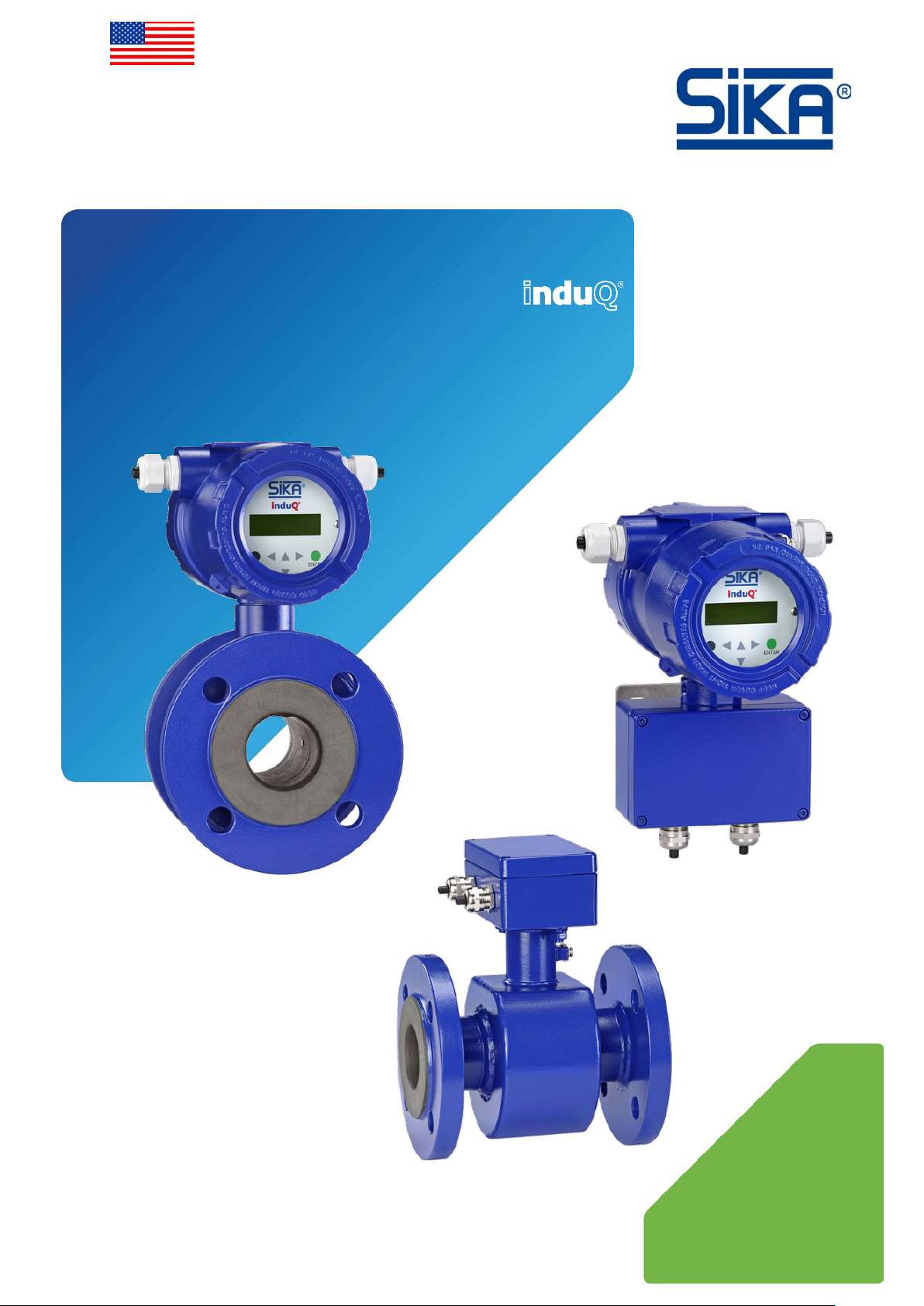
Magnetic Inductive
Flow Sensor
Series VMM
Please keep this operating manual for future reference.
If the device is resold, please provide the operating manual along with it.
Page 2

induQ
®
- Series VMM
Table of contents page
0 About this operating manual ......................................................................................... 4
1 Device description ......................................................................................................... 5
1.1 Delivery, unpacking and accessories ......................................................................... 6
1.2 Intended use ................................................................................................................ 7
1.3 Exclusion of liability .................................................................................................... 7
2 Safety instructions ......................................................................................................... 8
3 Construction and function ............................................................................................. 9
3.1 Construction ................................................................................................................ 9
3.2 Measuring principle .................................................................................................. 10
3.3 Functions ................................................................................................................... 10
4 Installation of VMM ...................................................................................................... 10
4.1 Installation instructions display electronics ............................................................ 11
4.2 Instructions on potential equalization and cathode protection ................................ 12
4.2.1 Potential equalization ........................................................................................... 12
4.2.2 Cathodic protectives ............................................................................................. 13
4.3 Sensor installation instructions ................................................................................ 14
4.4 Mounting .................................................................................................................... 16
5 Electrical connection ................................................................................................... 17
5.1 Mains and signal cable .............................................................................................. 17
5.2 Electrode and magnetic current line ........................................................................ 19
6 Commissioning ............................................................................................................ 19
7 Operation ..................................................................................................................... 21
7.1 Functional classes (main menu) ............................................................................... 24
7.1.1 Measured values ................................................................................................... 25
7.1.2 Password .............................................................................................................. 27
7.1.3 Totalizer ................................................................................................................ 29
7.1.4 Measurement processing ..................................................................................... 30
7.1.5 Flow ....................................................................................................................... 31
7.1.6 Pulse output .......................................................................................................... 34
7.1.7 Status output ......................................................................................................... 36
7.1.8 Current output ...................................................................................................... 37
7.1.9 Simulation ............................................................................................................. 38
7.1.10 Self-test ................................................................................................................ 40
7.1.11 Settings Sensor ..................................................................................................... 42
8 Errors and returns ...................................................................................................... 46
8.1 System errors............................................................................................................ 46
8.2 Self-test errors ......................................................................................................... 47
8.3 Return shipment to the manufacturer ..................................................................... 48
- 2 - © SIKA • Ba_VMM_us • 09/2018
Page 3

induQ
induQ
®
Copyright notice:
The reproduction, distribution and utilization of this operating manual as well as the communication of
its contents to others without express authorization is prohibited. Offenders will be held liable for the
payment of d
®
- Series VMM
9 Cleaning, maintenance, storage ................................................................................. 49
9.1 Cleaning ..................................................................................................................... 49
9.2 Maintenance .............................................................................................................. 49
9.3 Storage ...................................................................................................................... 50
10 Disassembly and disposal ........................................................................................... 50
11 Technical data.............................................................................................................. 51
11.1 Characteristics of the VMM ....................................................................................... 51
11.2 Materials table .......................................................................................................... 53
11.3 Dimensions and weights ........................................................................................... 54
11.3.1 Compact device ..................................................................................................... 54
11.3.2 Separate version (with wall bracket) .................................................................... 55
is a registered trademark of SIKA Dr. Siebert & Kühn GmbH & Co. KG.
amages. All rights reserved in the event of the grant of a patent, utility model or design.
Technical changes reserved - 3 -
Page 4
About this operating manual induQ
SIKA USA Inc.
info@sika-usa.com • www.sika-usa.com
DANGER! Danger to life due to non-observance!
WARNING! / CAUTION! Risk of injury!
cause considerable damage to property.
CAUTION! Electric current!
CAUTION! High temperature!
This sign indicates dangers resulting from high temperature that can lead to health defects or
considerable damage to property.
CAUTION! Material damage!
damage.
NOTICE!
tips or information.
NO DOMESTIC WASTE!
gether with domestic waste.
Pay attention to and comply with infor-
Check the specified points or notices.
®
- Series VMM
0 About this operating manual
• The operating manual is aimed at specialists and semi-skilled personnel.
• Before each step, read through the relevant advice carefully and keep to the specified
order.
• Thoroughly read and understand the information in the section "Safety instructions".
If you have any problems or questions, please contact your supplier or contact us directly at:
1500 S. Sylvania Ave. • Suite 111
Sturtevant • WI 53177
262 886-2695 • 262 898-0101
Hazard signs and other symbols used:
This sign indicates dangers which could lead to serious health defects or to death.
This sign indicates dangers that cause personal injuries that can lead to health defects or
This sign indicates dangers which could arise from handling of electric current.
This sign indicates actions which could lead to possible damage to material or environmental
ADHERE TO OPERATING MANUAL!
The device must not be disposed of to-
This symbol indicates important notices,
mation that is marked with this symbol.
Follow the specified instructions and steps.
Adhere to the given order.
Reference to another section, document or
source.
• Item.
- 4 - © SIKA • Ba_VMM_us • 09/2018
Page 5
induQ
®
- Series VMM Device description
1 Device description
The induQ
is performed using magnetic induction.
The VMM is used for measuring or dosing water and electrically conductive fluids. The com-
plete measuring instrument comprises the sensor and the related display electronics.
The display electronics is microprocessor controlled and programmable. It can be custom-
ized using a control unit.
The basic configuration settings such as display electronics calibration are realized at the
factory. Other settings are user definable.
Measurement data from sensors are processed by display electronics. It is designed for flow
velocities up to 33 ft/s (10 m/s).
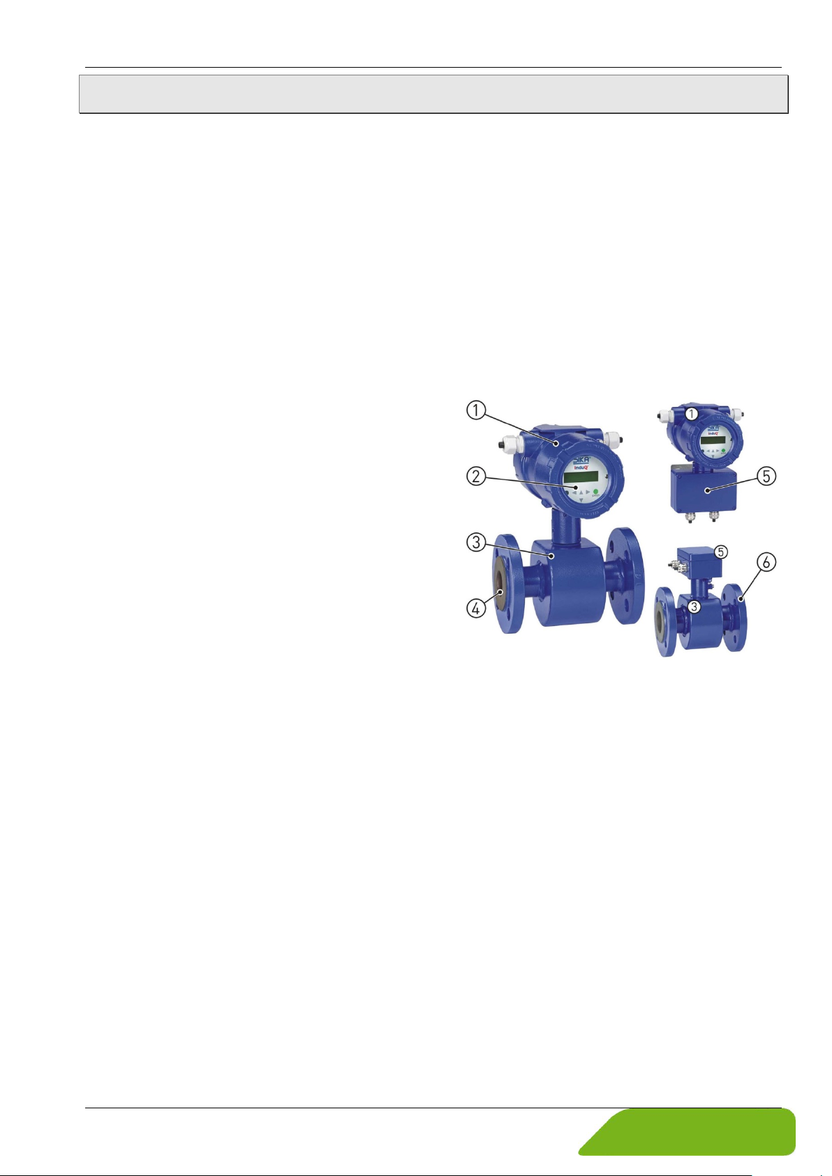
Components:
The most important components of the VMM are
Display electronics.
Indication and control panel.
Sensor.
Measuring tube.
Junction box.
Process connection.
®
of the VMM from SIKA is a flow sensor without moving parts. The measurement
Versions:
The VMM is available as a compact device
( Fig. left) or in separate design ( Fig. right).
Both designs are available with inner diameters from 1 ¼" to 8" with different features.
Type plates:
The type plates you can find at the backs of evaluation electronics and sensor.
They contain the most important technical data of VMM.
Technical changes reserved - 5 -
Page 6
Device description induQ
®
- Series VMM
1.1 Delivery, unpacking and accessories
All units have been carefully checked for their operational reliability before shipment.
Immediately after receipt, please check the outer packaging for damages or any signs of
improper handling.
Report any possible damages to the forwarder and your responsible sales representative.
In such a case, state a description of the defect, the type and the serial number of the device.
Report any in-transit damage immediately. Damage reported at a later date shall not be
recognized.
Unpacking:
Carefully unpack the unit to prevent any damage.
Check the completeness of the delivery based on the delivery note.
Scope of delivery:
1x VMM according to the order data.
1x operating manual.
certificates (optional)
IMPORTANT!
Use the type plate to check if the delivered unit corresponds to your order.
In particular, for devices with electrical components, check to see if the correct pow-
er supply voltage is specified.
Accessories:
Installation supplies (gaskets/seals, screws, etc.) are not included with the delivery.
Grounding rings.
Protection rings.
Sensor cable.
You can find details on the accessories in our catalog on the Internet.
- 6 - © SIKA • Ba_VMM_us • 09/2018
Page 7
induQ
®
- Series VMM Device description
1.2 Intended use
Magnetic inductive flow sensor VMM is only intended to be used for measuring and dosing /
batching the flow of electric conductive, liquid media
According to the Pressure Equipment Directive 2014/68/EU, only Group 2 fluids are permitted
to be used.
Due to the magnetic field, the device can be used to measure flow rates up to 33 ft/s (10 m/s)
and a minimum conductivity of 50 μS/cm, when using a synchronized static field.
WARNING! No safety component!
The flow sensor of the series VMM is not a safety component in accordance with Directive 2006/42/EC (Machine Directive).
Never use the VMM as a safety component.
The operational safety of the device supplied is only guaranteed by intended use. The specified limits ( § 4.3 "Sensor installation instructions") may under no circumstances be exceeded.
Before installing the device, check if the wetted materials of the device are compatible with
the media being used ( § 11.2 "Materials table").
CAUTION! Risk of injury due to high temperature!
Hot process media can lead to hot surfaces! Danger of burns with surface temperatures
above 158 °F (70 °C).
Take suitable protective measures, e.g. contact protection.
The contact protection must be devised so that the maximum ambient temperature on
the device is not exceeded.
Flow tube empty (partially filled). / Conductivity too low:
Faulty measurements can occur if the flow tube of the VMM is empty or partially filled or
if the conductivity of the fluid being used is too low.
Make sure that the flow tube of the VMM is always completely filled
( § 4.3 "Sensor").
Please observe the function "Empty pipe detection" ( p. 10).
Make sure that the fluid being used has a conductivity of at least 50 μS/cm.
Before ordering and installing, check that the device is suitable for your application.
1.3 Exclusion of liability
We accept no liability for any damage or malfunctions resulting from incorrect installation,
in-appropriate use of the device or failure to follow the instructions in this operating manual.
Technical changes reserved - 7 -
Page 8
Safety instructions induQ
®
- Series VMM
2 Safety instructions
Before you install the VMM read through this operating manual carefully. If the instructions contained within it are not followed, in particular the safety guidelines, this could
result in danger for people, the environment, and the device and the system it is con-
nected to.
The VMM corresponds to the state-of-the-art technology. This concerns the accuracy, the
operating mode and the safe operation of the device.
In order to guarantee that the device operates safely, the operator must act competently and
be conscious of safety issues.
SIKA provides support for the use of its products either personally or via relevant literature.
The customer verifies that our product is fit for purpose based on our technical information.
The customer performs customer- and application-specific tests to ensure that the product
is suitable for the intended use. With this verification all hazards and risks are transferred to
our customers; our warranty is not valid.
Qualified personnel:
The personnel who are charged for the installation, operation and maintenance of the
VMM must hold a relevant qualification. This can be based on training or relevant tuition.
The personnel must be aware of this operating manual and have access to it at all times.
The electrical connection should only be carried out by a fully qualified electrician.
General safety instructions:
In all work, the existing national regulations for accident prevention and safety in the
workplace must be complied with. Any internal regulations of the operator must also be
complied with, even if these are not mentioned in this manual.
Degree of protection according to EN 60529:
Ensure that the ambient conditions at the site of use does not exceed (comply with) the
requirements for the stated protection rating ( § 11.1 "Characteristics of the VMM").
Take appropriate measures to ensure that the medium does not freeze.
Only use the VMM if it is in perfect condition. Damaged or faulty devices must be checked
without delay and, if necessary, replaced.
When fitting, connecting and removing the VMM use only suitable, appropriate tools.
Do not remove or obliterate type plates or other markings on the device, as otherwise the
warranty is rendered null and void.
- 8 - © SIKA • Ba_VMM_us • 09/2018
Page 9
induQ
Special safety instructions:
®
- Series VMM Construction and function
Danger! Electric current!
Particular care must be taken if the front window of the housing becomes fogged over or
discolored because moisture, water or product might seep through the wire sheath into
the terminal compartment in the housing!
Ingress protection IP67 is only achieved if suitable and tightly screwed down cable glands
or conduits are used. If the cable glands are only tightened manually water may leak into
the terminal compartment in the housing.
Electromagnetic compatibility is only achieved if the electronics housing is closed. Leav-
ing the enclosure open can lead to electromagnetic disturbances.
Further warnings that are specifically relevant to individual operating procedures or activities
can be found at the beginning of the relevant sections of this operating manual.
3 Construction and function
3.1 Construction
The VMM comprises a sensor and the display electronics. The sensor is used to measure fluid media. The display electrodes generate the coil current required for the magnetic field and
prepares the induced voltage applied to the electrodes.
The VMM does not need any moving parts to make measurements. The inside
of the measuring tube is completely open, allowing the fluid to flow unhindered through the measuring tube.
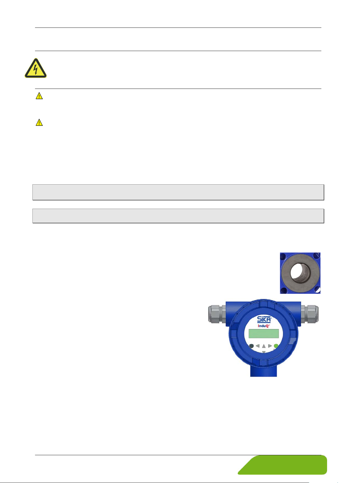
Display electronics:
The display electronics has a backlit LCD.
6 buttons are used for operation. That facilitates easy
configuration of the display electronics.
Furthermore the display electronics has an analog
0/4 … 20 mA current output, a pulse or frequency output and a status output.
Technical changes reserved - 9 -
Page 10
Installation of VMM induQ
®
- Series VMM
3.2 Measuring principle
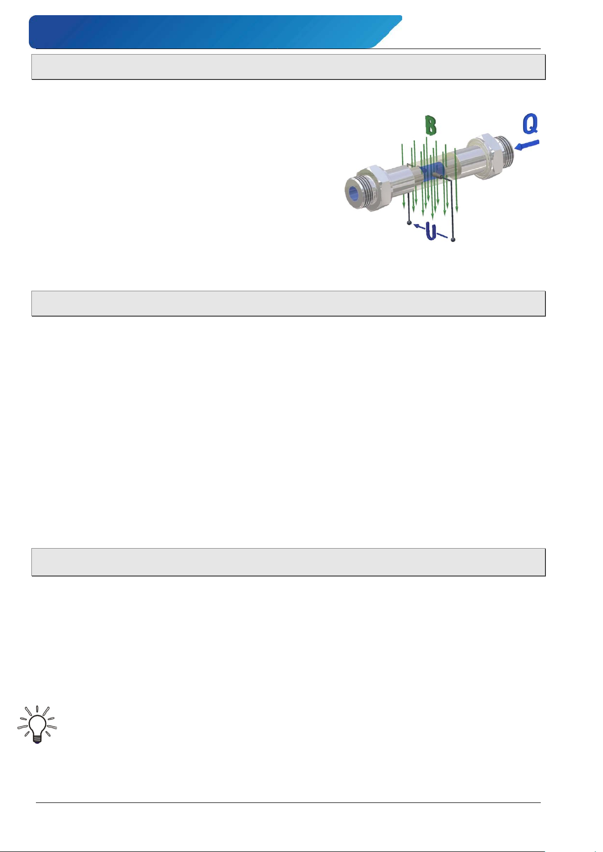
The magnetic inductive flow sensor operates on the inductive principle, i.e., a direct current
is generated by the movement of a conductor in a magnetic field:
The measuring pipe of the VMM is in a magnetic
field (B).
An electrically conductive medium (Q) passes through
the pipe. During this, the positive and negative load carriers are inversely deflected.
A voltage arises which is perpendicular to the magnetic
field, which is tapped through both electrodes.
The voltage induced during this is proportional to the
average flow velocity of the fluid.
The electronics of the VMM converts the induced voltage into a flow-proportional frequency
signal.
3.3 Functions
Empty pipe detection:
The electronic display unit has the ability for an empty pipe detection, which can be activated
and deactivated.
The operating reliability depends on the conductivity of the liquid medium and the cleanliness
of the electrodes.
As higher the conductivity is, as more reliable operates the empty pipe detection.
Insulation coatings on the electrodes surface worse the empty pipe detection.
Safety of operation:
A comprehensive self-monitoring system ensures maximum safety of operation.
• Potential errors can be reported immediately via the configurable status output. The
corresponding error messages will also be displayed on the display of the display electronics. A failure of the auxiliary power can also be detected via the status output.
• All outputs are electrically isolated from the auxiliary power, the sensor circuit and from
each other.
4 Installation of VMM
Before installing, check that
the wetted materials of the device are suitable for the liquid being used
( § 11.2 "Materials table").
the equipment is switched off and is in a safe and de-energized state.
the equipment is depressurized and has cooled down.
Please observe in particular "Instructions on potential equalization and cathode protec-
tion" ( § 4.2).
Suitable tools:
Use only suitable tools of the correct size.
- 10 - © SIKA • Ba_VMM_us • 09/2018
Page 11
induQ
®
- Series VMM Installation of VMM
4.1 Installation instructions display electronics
Compact version (standard):
For the compact version the display electronics housing is mounted on the sensor. Therefore
no cable is necessary between sensor and display electronics.
Remote version (optional):
The display electronics needs to be mounted separately from the sensor if:
• the mounting area is difficult to access or there is a lack of space,
• medium and ambient temperatures are extremely high,
• there is strong vibration.
The display electronics has to be mounted free of vibrations!
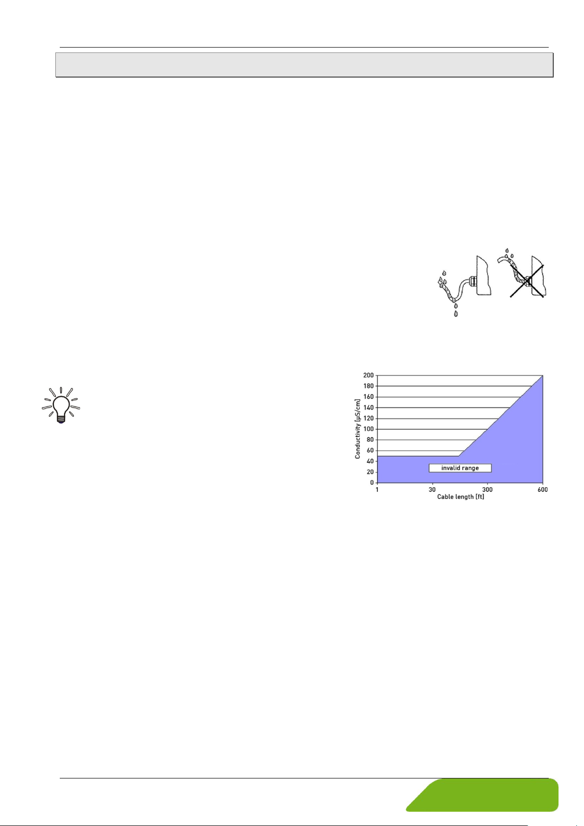
Make sure that the cables are properly installed at high humidity
and wet conditions.
The electrode cable must be fixed. If the conductivity of the medium
is low, cable movements may change the capacity considerably and
thus disturb the measuring signal.
Do not lay the cables close to electrical machines and switching elements.
Equipotential bonding must be ensured between sensor and display electronics.
IMPORTANT! Pay attention to the maximum cable
length!
For the separate version, the minimum permissible conductivity of the medium is determined by
the distance between the sensor and the display
electronics.
The maximum cable length to ensure accuracy is
656 ft (200 m) ( p. 17 "Connecting cables").
Technical changes reserved - 11 -
Page 12
Installation of VMM induQ
®
- Series VMM
4.2 Instructions on potential equalization and cathode protection
4.2.1 Potential equalization
The signal outputs (process outputs and the mains supply of the VMM are galvanic isolated
from each other. The housing and the interference filter of the mains supply are connected to
PE.
The electrodes and measuring electronics are related to the potential of the function ground
FE of the sensor. FE is not connected to PE, but may be connected with each other in the
sensor junction box. If the sensor is grounded by using ground disks (grounding rings), these
must in connected with the function ground FE.
At a separate assembly of sensor and display electronics the outer screen of the connecting
cable is connected to the housing of the display electronics and has PE potential. The inner
screens of the electrode line are connected to FE inside the junction box of the sensor and to
the mass (GND) of the display electronics.
Details of all wirings, terminals and drawing can be found in § 5 "Electrical connection".
IMPORTANT!
The display electronics can only process the measuring signal interference-free if this
voltage is referenced to a fixed potential (ground).
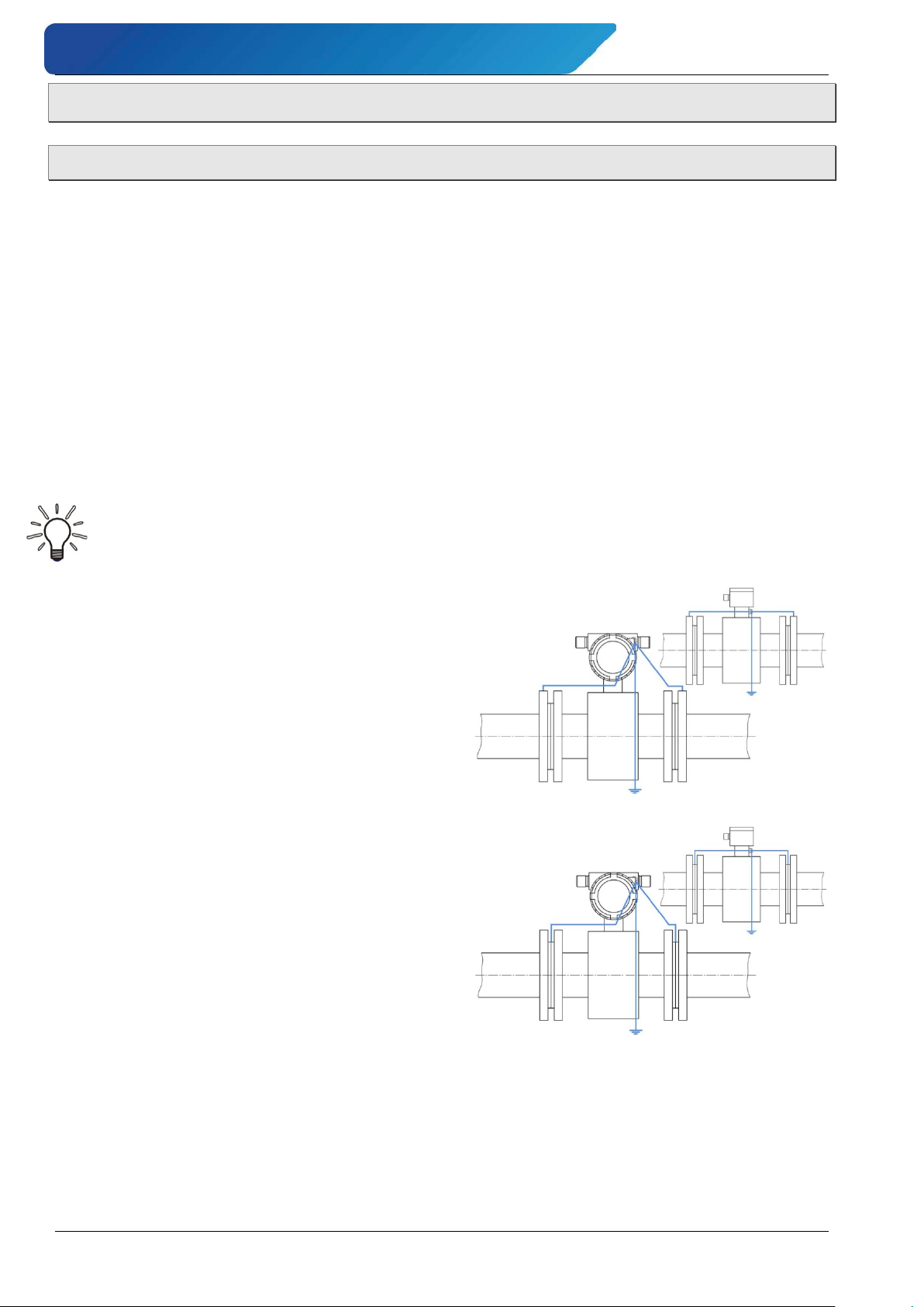
Potential equalization on electrically conductive
pipes:
The sensor is electrically connected to the pipeline in the sense of a potential equalization.
Thus, the pipeline is grounded, and the media and
therefore the signal voltage have a solid signal
common.
Potential equalization on electrically insulated pipes:
When using pipes lined with electrical insulation,
plastic tubing or concrete conduits, a separate
grounding washer is used to ground the measuring media. The grounding washer is installed between the pipeline connection and the sensor’s
flange and the ring’s inside contacts the media.
Contrary to the diagram shown below, one
grounding washer on the inflow side is sufficient.
If bidirectional measurements are to be taken,
one grounding washer must be installed on either
side.
Protection washers or protection rings can also be used as grounding component; or special
grounding electrodes, incorporated in the sensor, may be installed.
Grounding electrodes are more economical than grounding washers. However, it must be
ensured that noticeable differences in potential within the equipment are eliminated, otherwise the grounding electrodes will electrolyze and be destroyed.
- 12 - © SIKA • Ba_VMM_us • 09/2018
Page 13
induQ
®
- Series VMM Installation of VMM
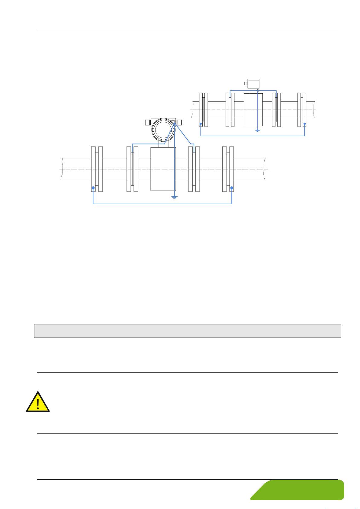
Potential-free installation of the sensor:
If the pipelines cannot be grounded, due to operational reasons, the sensor must be installed
voltage free. To do this, a separate cable must be used to electrically connect these segments of the pipeline (min. 11.8 kcmil (6 mm²)).
An electrical connection occurring between the sensor and any material used for the installation must be avoided. Insulating segments must be installed between the sensor and the
pipeline (e.g. PVC pipes or similar).
Subsequently, grounding washers are used to electrically connect the media with the display
electronics. The display electronics must not be connected with the protective ground conductor. This may only be done, if the auxiliary power is 24 VDC.
Potential equalization in separate design:
Create the potential equalization in the separate design the same as described in the above
sections. For the potential equalization, the display electronics and the sensor are connected
to each other through Pin 7 of the connecting cable.
4.2.2 Cathodic protectives
Using a cathodic protective unit to avoid corrosion, which put a voltage to the tube wall, it
must be connected to terminal FE. The boards, control panel and internal switches of the
display electronics are on the same potential as FE.
CAUTION! Electric current - comply with limits!
According to EN 61010-1:2012 all electrical circuits with „protective safety isolation without any protection against contacts” must observe the following maximum voltages:
• Maximum AC voltage (V
) 33 V
eff
• Maximum DC voltage 60 V.
Make sure that no higher potential is connected to FE.
Technical changes reserved - 13 -
Page 14
Installation of VMM induQ
®
- Series VMM
4.3 Sensor installation instructions
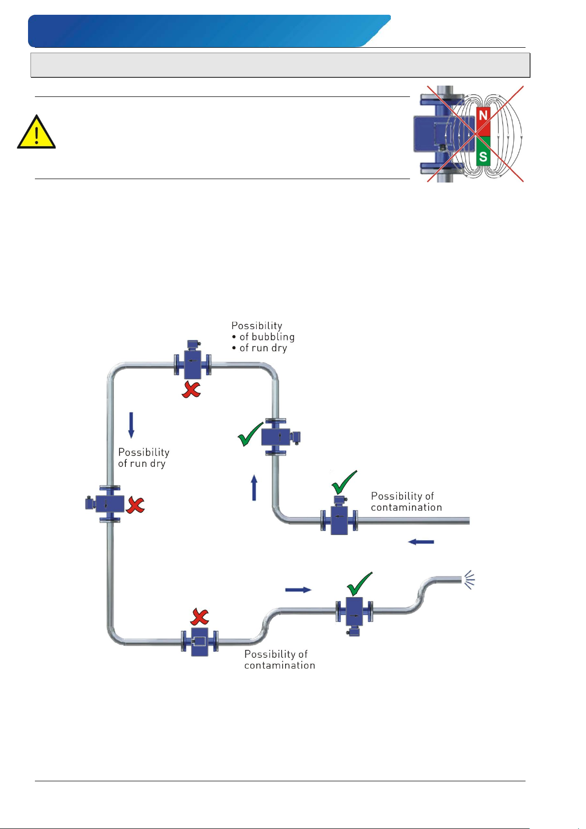
CAUTION! Risk of malfunction due to external magnetic fields!
Magnetic fields close to the device can cause malfunctions and
should be avoided.
Ensure that no external magnetic fields are present at the in-
stallation site of the VMM.
Please observe § 1.1 "Delivery, unpacking and accessories" and the following installation instructions:
General:
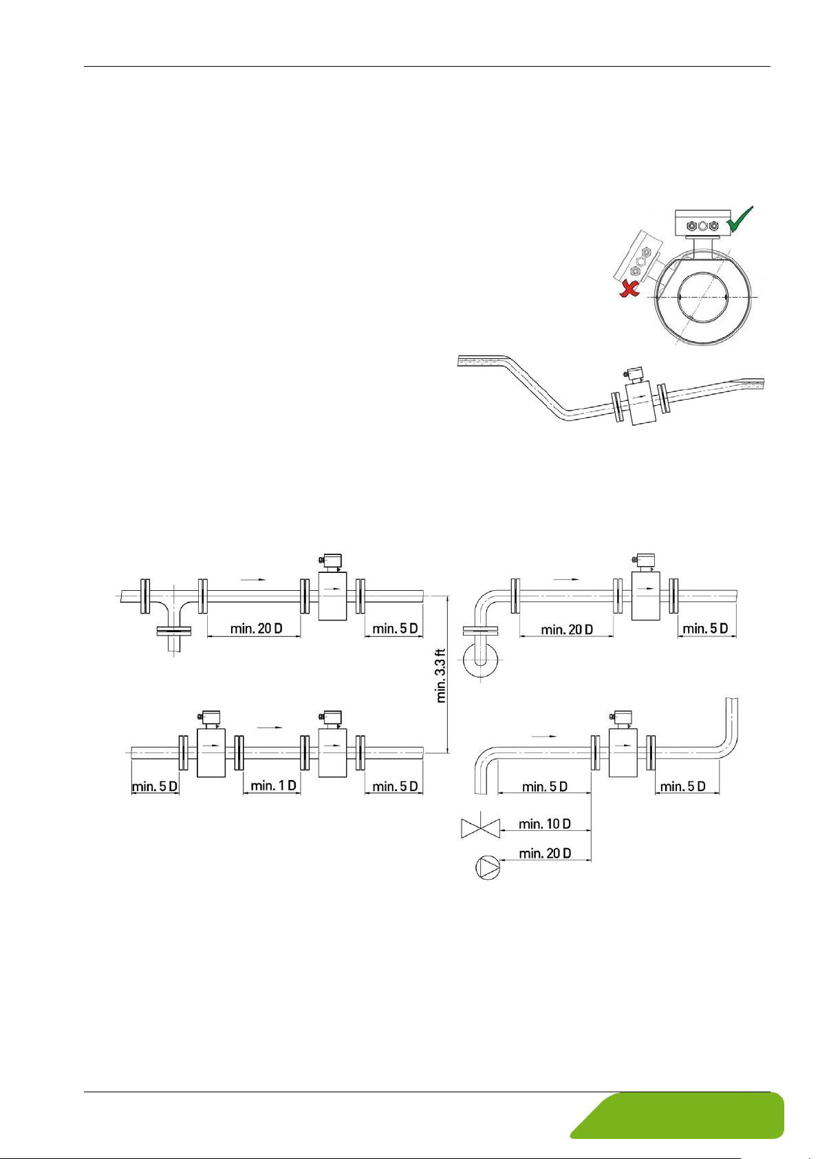
• The VMM can always be installed at any point on the pipeline in the horizontal as well as
in vertical sections.
Ideally, the sensor should be installed in a pipeline with a sufficient straight run, both before and after the measuring point.
• Basically, the measuring principle does not depend on the flow profile. You should use
straight inlet and outlet sections according to the inner diameter (ID). An inflow path of
5 x ID and an outflow zone of at least 2 to 3 x ID is required.
• The flow sensor is only suitable for application in completely filled pipe systems. With a
free pipe outlet, the sensor should not be installed in pipe sections that could run empty
(e.g., downpipes).
- 14 - © SIKA • Ba_VMM_us • 09/2018
Page 15
induQ
®
- Series VMM Installation of VMM
If the sensor must be installed in a down pipe, ensure that portion of the pipeline is always filled 100% with the media.
• Due to possible accumulation of gases, the sensor should not be installed at the highest
point of a pipeline.
• It must be ensured, that the axes of the electrodes are running
horizontally to avoid erroneous measurements due to deposits or
air bubbles on the electrodes.
Also, note that in case of deviations from horizontal, the functioning of the Empty pipe detection ( p. 10) is limited.
Installation in unfilled pipeline:
• If a pipeline is not always filled, or in case of
an open channel (drainage), the sensor must
be installed in a siphon. That means the flow
tube cannot run dry and is always filled with
measured medium.
Installation between tees, valves and pumps:
Always maintain the distance of the pipe's straight run. If these distances cannot be maintained, flow conditioners must be installed or pipes with smaller diameter must be used.
If several sensors are installed in series, the distance between each sensor must be equal to
the length of one sensor. If two or more sensors are to be installed in parallel, the distance
between sensors must be at least 3.3 ft (1 m).
Technical changes reserved - 15 -
Page 16
Installation of VMM induQ
®
- Series VMM
Measures during malfunctions:
In case of malfunctions in the inflow section due to vortexing (e.g. after pipe elbows, at tangential inclusions or with a half-open gate before the sensor), measures for normalization of
the flow profile are necessary.
The appropriate steps are:
• increasing the inflow and outflow zones
• using flow conditioners
• reducing the inner diameter of the pipe
4.4 Mounting
As a compact device, the VMM is installed directly into the pipeline. With the separate design,
the sensor is installed in the pipeline. The display electronics can be attached to the wall with
the bracket.
IMPORTANT NOTICES:
• Only use suitable gaskets for installation.
• Observe the flow direction indicated on the type plate and
on the back site of the sensor.
• Observe the mounting dimensions ( § 11.3 “Dimensions
and weights”).
Select an appropriate location for installation
( § 4.3 "Sensor installation instructions").
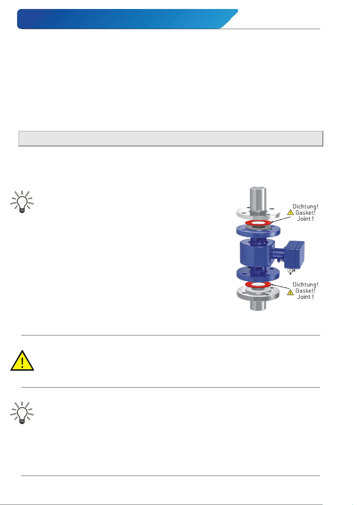
To ensure the best possible measuring accuracy, a vertical
installation position with increasing flow is preferable (no collecting of dirt deposits).
Install the appropriate screwed connections at the installa-
tion location.
Insert the VMM together with the gaskets.
Connect the flange connections corresponding to the re-
quirements of their use.
WARNING! Risk of injury or material damage!
Incorrect gaskets and connection materials plus improper assembly can lead to injuries
or material damage.
During installation, comply with the requirements that result from your application.
Maintain the required tightening torques.
IMPORTANT! Weather protection required
In the case of an outdoor installation, the device must be protected against direct solar
irradiation with a weather shield.
- 16 - © SIKA • Ba_VMM_us • 09/2018
Page 17
induQ
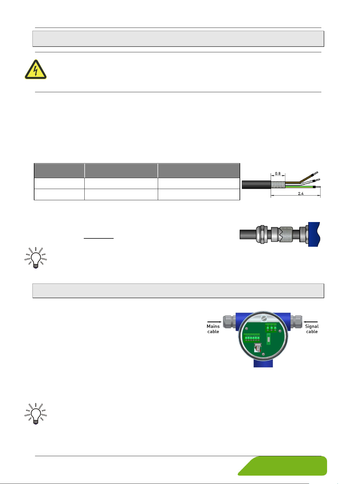
Cable ends dimension:
®
- Series VMM Electrical connection
5 Electrical connection
CAUTION! Electric current!
The electrical connection of the VMM should only be carried out by a fully qualified electrician.
De-energize the electrical system before connecting the VMM.
Make the electrical connection of the VMM through the terminal strips in the interior of the
display electronics.
For the separate design, the sensor cable for the electrodes and the magnetic current are
required in addition. They are connected through the terminal strips in the junction boxes of
the display electronics and the sensor.
Connecting cables:
When connecting the VMM, use the following cable depending on the cable lengths:
Cable length Wire cross-section
≤ 32,8 ft (10 m) ≥ 0.5 kcmil (0.25 mm2) LIYCY-CY TP 2x2x0.25 mm2
> 32,8 ft (10 m) ≥ 1.5 kcmil (0.75 mm2) LIY-TPC-Y 2x2x0.75 mm2
Example
The cables are each twisted in pairs and shielded. In order to protect the cable from external
interference, the pair wires are covered by an additional, overall shield.
The outer shield is grounded by means of special EMC-compliant
cable glands at both ends of the cable.
IMPORTANT! Potential equalization required!
Comply with the instructions on Potential ( § 4.2.1).
5.1 Mains and signal cable
The connection of the mains and signal cable are the same in both versions.
The terminal strips are located behind the rear hous-
ing cover.
Screw the rear cover from the housing counter
clockwise.
Only use signal cables as specified in chapter
"Connecting cables“.
Lay the signal cables separately from cables with
voltages >60 V.
Avoid laying signal cables close to large electrical installations.
IMPORTANT! Pay attention to the clamping area of the cable gland!
To guarantee the protection class as per DIN EN 60529, the connection cable being used
must have a sheathing diameter that matches the cable gland.
Technical changes reserved - 17 -
Page 18
Electrical connection induQ
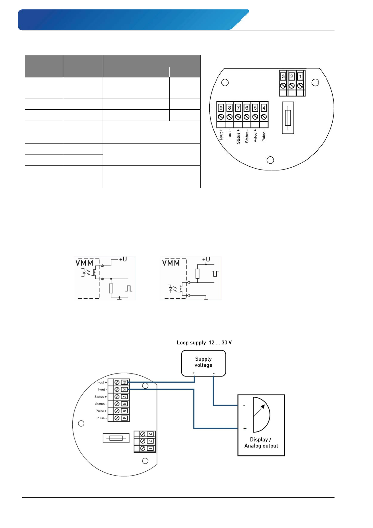
115 / 230 VAC
24 VAC
Pull-up wiring:
Pull-down wiring:
Switching values:
Recommendation Pull-Up / Pull-Down resistance ~5 kΩ.
Terminal assignment:
®
- Series VMM
Terminal Label Function
1 PE
Protective conductor
-/-
2 N Neutral conductor 0 V
3 L Phase 24 V
4 Pulse -
Pulse output (passive)
5 Pulse +
6 Status -
Status output (passive)
7 Status +
8 Current 9 Current +
Current output
(active / passive)*
* permanently configured in factory.
Wiring pulse / status output (passive):
The external wiring for the pulse output and the status output is the same.
The wiring for the pulse output is done via terminals 4 and 5 and for the status output via
terminals 6 and 7.
UN: 24 V
: 30 V
U
max
: 60 mA
I
max
: 1.8 W
P
max
Wiring current output (passive):
An external voltage supply is required when connecting the passive current output.
- 18 - © SIKA • Ba_VMM_us • 09/2018
Page 19
induQ
* The wires green-yellow and blue are not connected.
®
- Series VMM Commissioning
5.2 Electrode and magnetic current line
For the separate design, the electrodes and magnetic current cable must be connected in
addition.
CAUTION! Electric current!
Do not connect or disconnect the field coil cable
before the primary power of the meter has been
disconnected!
Connect through the terminal strips in the junction
boxes of the display electronics and the sensor.
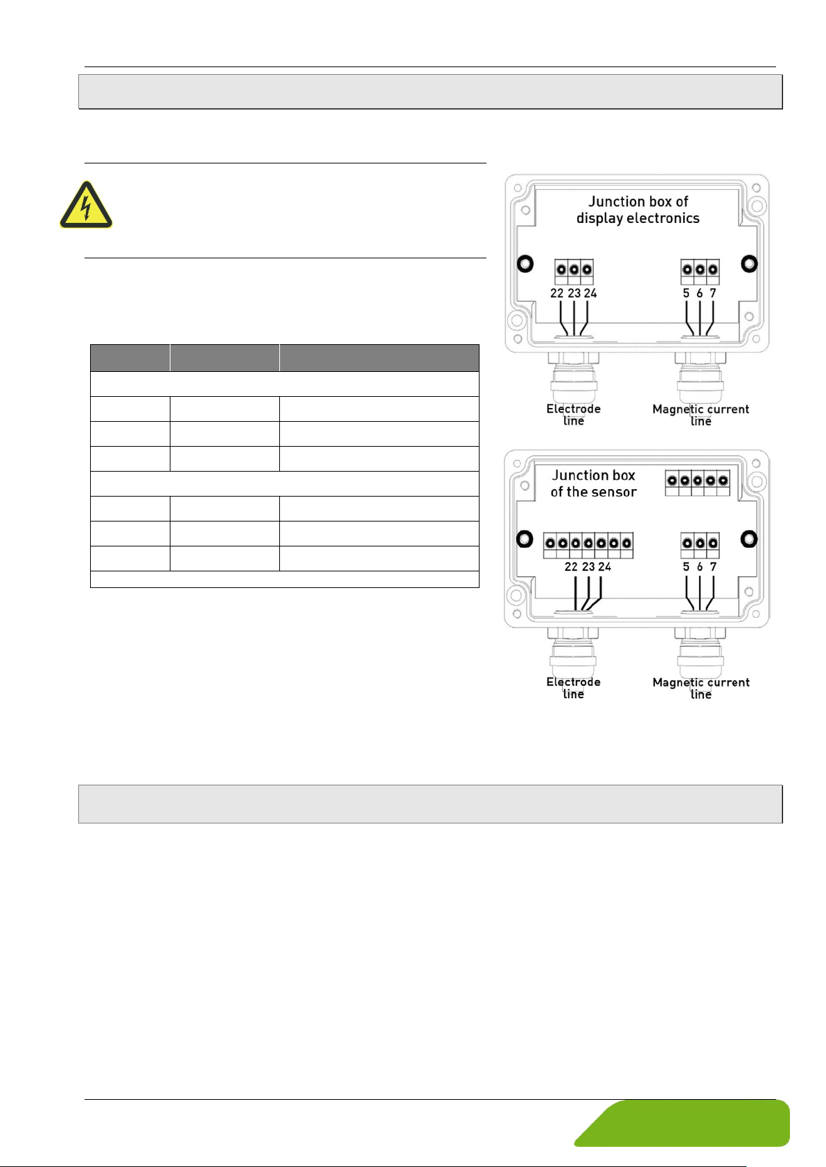
Pin assignment:
Terminal Wire color Function
Magnetic current line (3 wire)
5 brown Magnetic field current 1
6 white Magnetic field current 2
7 green-yellow Potential equalization / PE
Electrode line (5 wire*)
22 red Measuring ground
23 brown Electrode 1
24 white Electrode 2
Only use cables as specified in chapter
"Connecting cables“.
The outer shield is grounded by means of special
EMC-compliant cable glands at both ends of the
cable.
The inner shields are connected to terminal 7 and 22 respectively.
6 Commissioning
Before switching on the VMM for the first time, please observe the following instructions.
Check that
the VMM has been installed correctly and that all screw connections are sealed.
the electrical wiring has been connected properly.
the measuring system is vented by flushing.
Startup conditions:
The device is not subject to specific startup conditions. However, pressure surges should be
avoided.
Technical changes reserved - 19 -
Page 20
Commissioning induQ
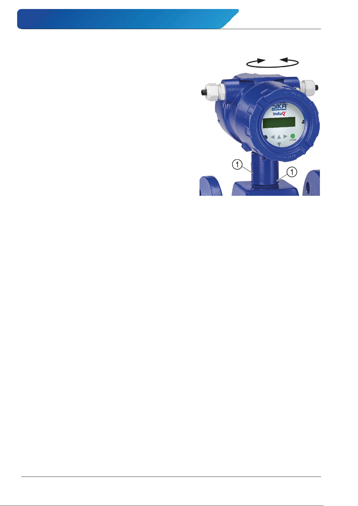
Change the orientation of the display electronics (only compact version)
The display electronics of the compact version isn't
rigidly connected to the sensor but can be turned by
± 180°.
The display electronics has been factory-installed so
that in case of a horizontal piping and a flow direction
from left to right the set orientation is in the correct
position.
Follow the steps to change the orientation of the display electronics:
Loosen the two setscrews .
Turn the display electronics in the desired posi-
tion.
Tighten the two setscrews again.
®
- Series VMM
- 20 - © SIKA • Ba_VMM_us • 09/2018
Page 21
induQ
®
- Series VMM Operation
7 Operation
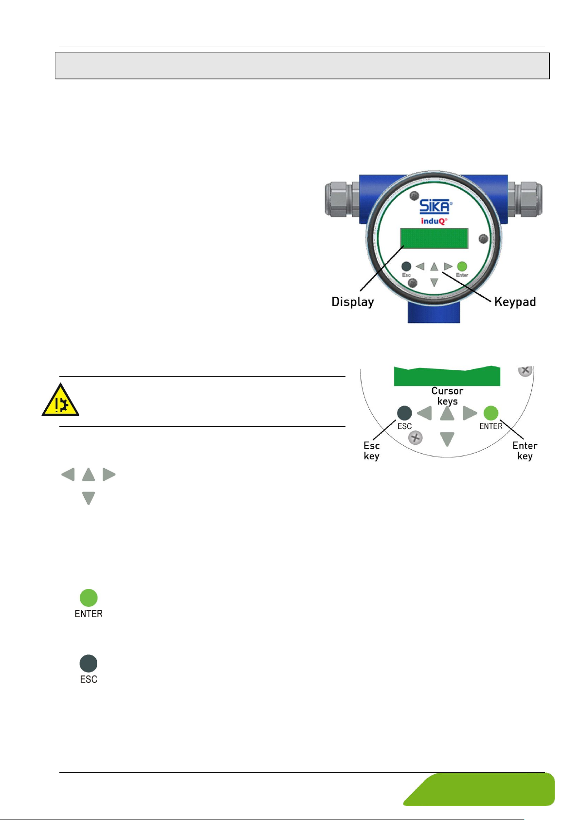
The display electronics are controlled through the display and the keypad.
Display:
The display electronics has an integrated back lighted, alphanumeric display with two 16character lines (format 0.4 x 2.0 in). Measurement data and settings can be read directly
from this display
The LCD is designed to be operated at temperatures ranging from − 4 °F to + 122 °F without being damaged.
Near freezing temperatures the display becomes
slow. The readability of the measured values is
reduced.
At temperatures below 32 °F, only static values
(parameter settings) can be displayed.
At temperatures exceeding 122 °F, contrast decreases substantially on the LCD and the liquid
crystals can dry out.
Keys and their functions:
There are six keys for operating and changing the settings.
CAUTION! Material damage!
Do not press these keys with sharp or sharpedged objects such as pencils or screwdrivers!
Cursor keys:
These keys are used for
• change numerical values.
• give YES/NO answers.
• select parameters.
Each key is assigned a symbol as follows:
Cursor key, right arrow; Cursor key, left arrow;
Cursor key, up arrow; Cursor key, down arrow.
ENTER key:
The ENTER key is used for entering the parameter level from the menu level.
All entries are confirmed with the ENTER key.
ESC key:
The ESC key is used to cancel the current action and leads to the next higher level. This is used for rollback.
Pressing ESC key twice moves you directly to the MEASURED VALUES functional
class.
Technical changes reserved - 21 -
Page 22
Operation induQ
®
- Series VMM
Operating modes:
The display electronics of the VMM has two different operating modes:
1. Display.
In display mode, measured values can be displayed in various combinations and the same
applies to the VMM settings. Parameter settings cannot be changed in this mode.
Display mode is the standard (default) operating mode when the device is switched on.
2. Programming.
The parameters of the VMM can be changed in this operating mode. After entering the corresponding password, either only the customer-modifiable functions (customer password) or
all functions (service password) are released for modification.
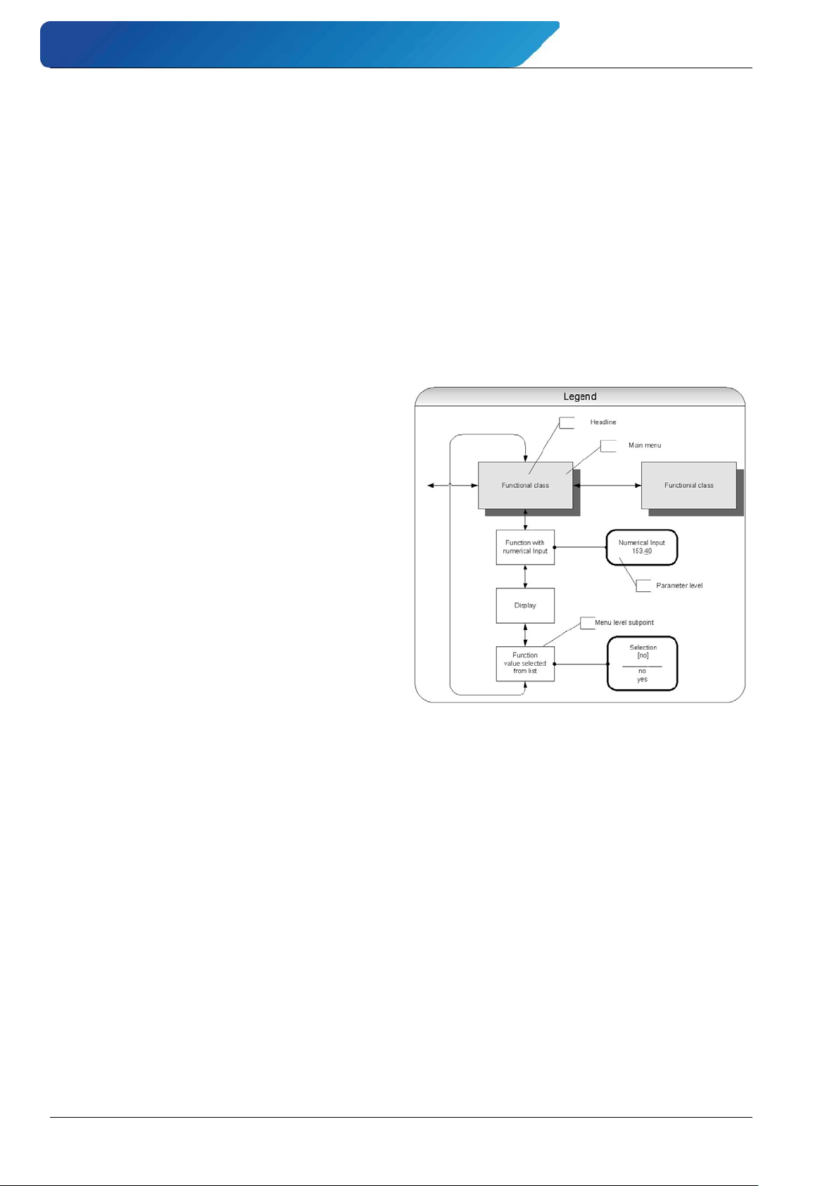
User interface:
The user interface is hierarchically structured.
At the top level you can find the Functional
classes which are displayed as headings. It
represents a kind of logical groups for values
and parameters.
The second level is the menu level and it includes either parameters or further submenus.
The third and lowest level is the parameter
level, which only includes parameters.
All functional classes are interlinked horizontally, while all sub items of a functional class
are interconnected vertically.
Functional classes, functions and parameters:
Functional classes are strictly written in upper case letters (headings). For the functions and
parameters at the next levels upper und lower case is used.
The various functional classes and functions are described in chapter "Functional classes
(main menu)" ( p. 24).
For the menu level always the first line of the LCD the corresponding heading for the menu
item and the contents of second line is context-sensitive:
information, YES/NO answers, alternative values, numerical values (with dimensions, if applicable) or error messages.
If the user attempts to modify values for any of these parameters without entering the required password, the message “Access denied” will be displayed. See also "Operating
modes" ( p. 22) and "Passwords" ( p. 23).
The various categories for submenu items are described below.
- 22 - © SIKA • Ba_VMM_us • 09/2018
Page 23
induQ
Function name
[selection]
Function name
-4.567 Unit
®
- Series VMM Operation
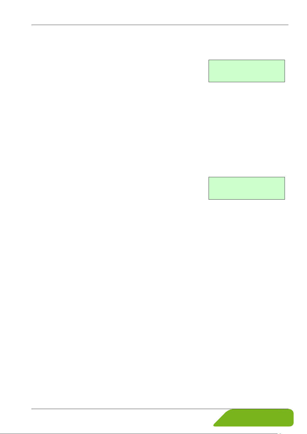
Selection window / make a selection:
For the selection window, the first line of the LCD always displays the heading, while the second line displays the current setting.
For the selection window, the first line of the LCD always displays the heading, while the second line displays the current
setting. This setting is shown in square brackets if the system is
in programming mode ( "Operating modes", p. 22).
In Programming mode, i.e. after a password has been entered the operator can navigate to
the desired setting by using the key or the key. The actual selection will be confirmed by
pressing ENTER key.
Pressing the ESC key will discard changes.
Input window / modify a value:
For the input window, the first line of the LCD always shows the heading, while the second
line shows the current setting.
Modifications can only be made in Programming mode ( "Operating modes", p. 22).
To move the flashing cursor from one decimal place to another,
use the or keys.
To in-/decrease the value of the decimal place, which is highlighted, by 1, use the or key.
To change the minus and plus sign, place the cursor in front of the first digit. To confirm and
apply the change, press the ENTER key.
To discard the changes, press Esc
Passwords:
Programming mode is password protected. Entering the customer password will allow all
changes that are permissible for customers.
This password can be changed when the device is first put into operation. Therefore changes
should be kept in a safe place.
The factory setting for the VMM customer password is: "0002".
The service password allows modification of all functions and parameters. This password is
not given to customers.
Technical changes reserved - 23 -
Page 24
Operation induQ
®
- Series VMM
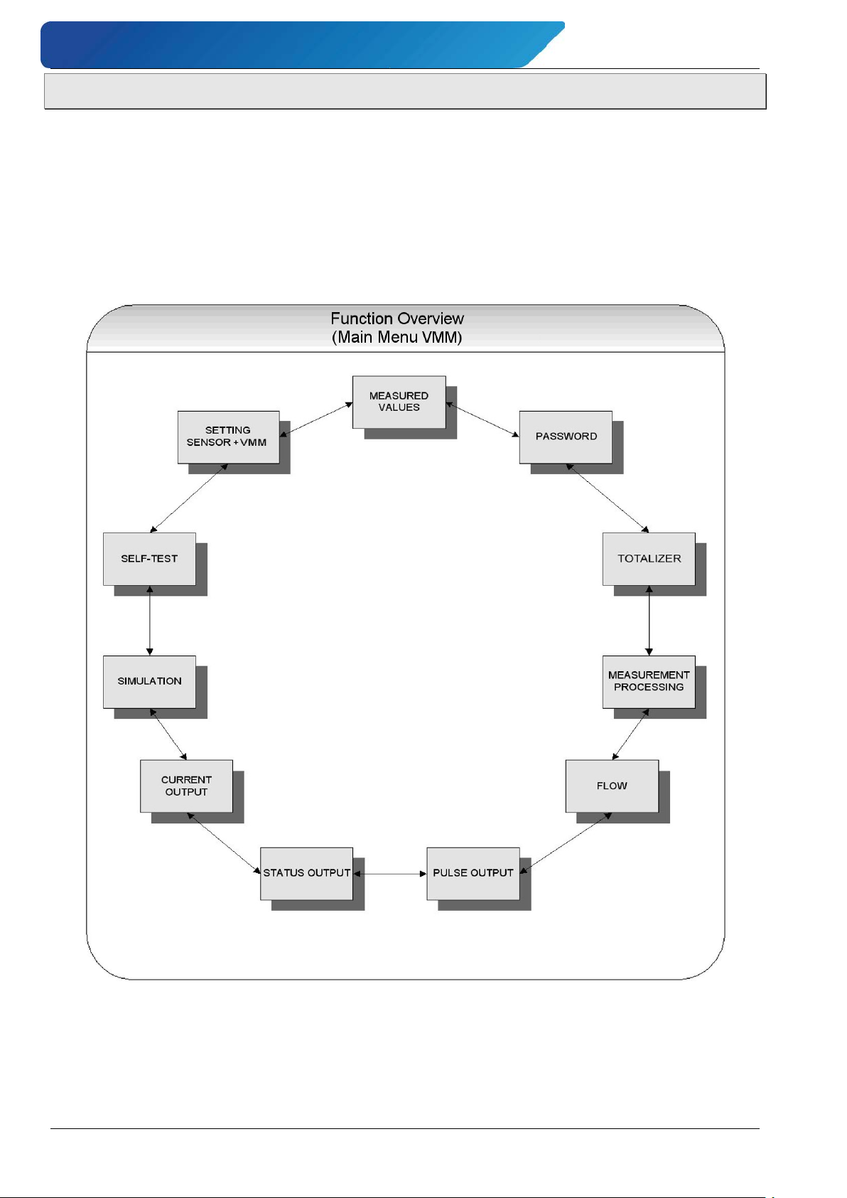
7.1 Functional classes (main menu)
The software functions of the VMM are divided into functional classes. They are arrayed in a
circle and can be navigated by using the or cursor keys. To go back to your starting point
(the MEASURED VALUES functional class) press Esc.
In the following, all software functions that can be accessed using the customer password
are described.
Functions that are only accessible to the vendor (service functions) are not described in this
manual.
- 24 - © SIKA • Ba_VMM_us • 09/2018
Page 25
induQ
Volume flow.
50.0 USG/min
Totalizer 1 fwd.
+000001.0 USG
Totalizer 2 fwd.
+000001.0 USG
®
- Series VMM Operation
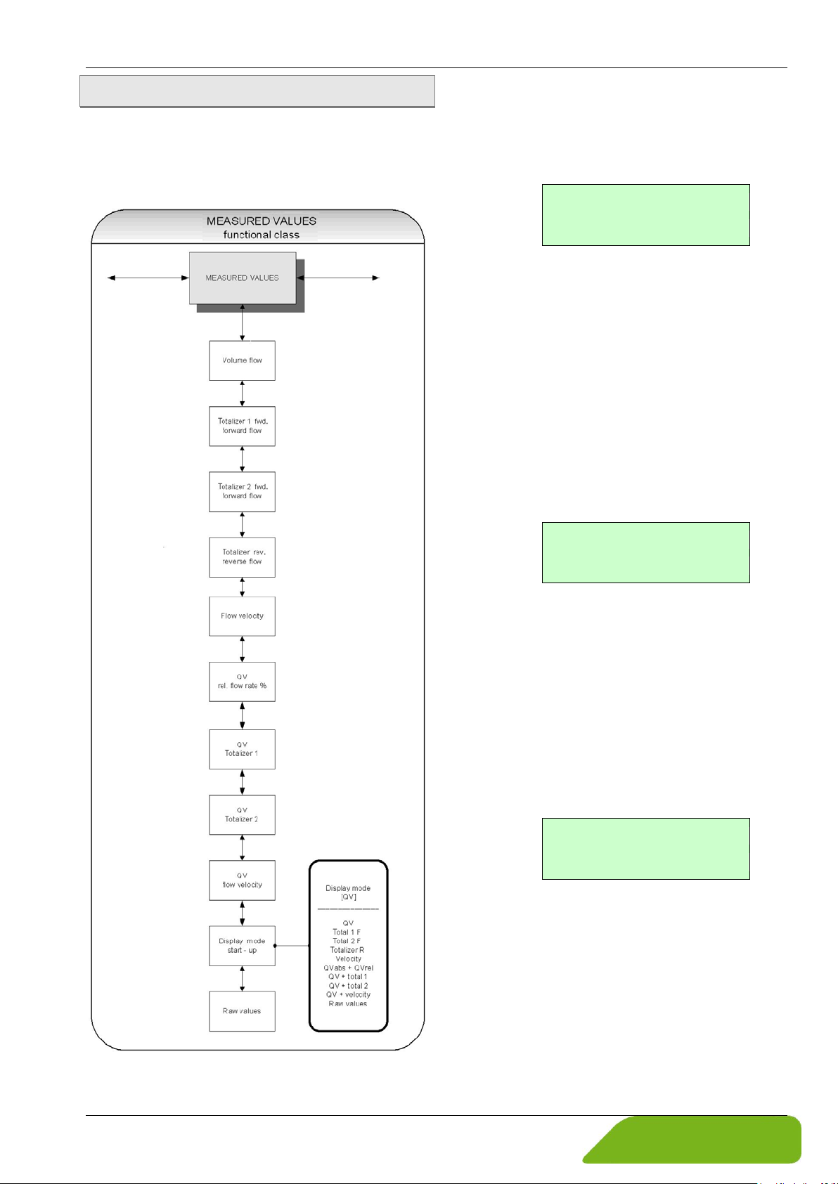
7.1.1 Measured values
The MEASURED VALUES functional class includes all functions for displaying the measured values.
Volume flow rate:
If you select the function volume flow the
current value for the volume flow will be displayed.
Example:
The displayed unit is defined in the functional
class FLOW using the function volume flow
unit
.
Totalizer forward 1:
Totalizer forward 1 and totalizer forward 2
are independent totalizers that can also be
reset separately.
With totalizer 1, for example, you can measure the yearly or monthly volume.
If you select the function totalizer for-
ward 1
, the current value of the totalizer
forward 1 will be displayed.
Example:
The displayed unit is defined in the functional
class TOTALIZER using the function total-
izer unit
.
Totalizer forward 2:
The function is identical with totalizer 1. For
example, totalizer 2 can be used as a daily
counter.
If you select the function totalizer for-
ward 2,
the current value of the totalizer
forward 2 will be displayed.
Example:
Technical changes reserved - 25 -
The displayed unit is defined in the functional
class TOTALIZER using the function total-
izer unit
.
Page 26
Operation induQ
%100
limit rangelower limit rangeupper
limit rangelower
abs
Q
rel
Q ⋅
−
−
=
Totalizer rev.
000000.0 USG
flow velocity
1.5 m/s
Relative flow
95.3 %
XXX.X USG
T1 XXX.XX USG/min
XXX.X l
T2 XXX.XX USG/min
®
- Series VMM
Totalizer reverse:
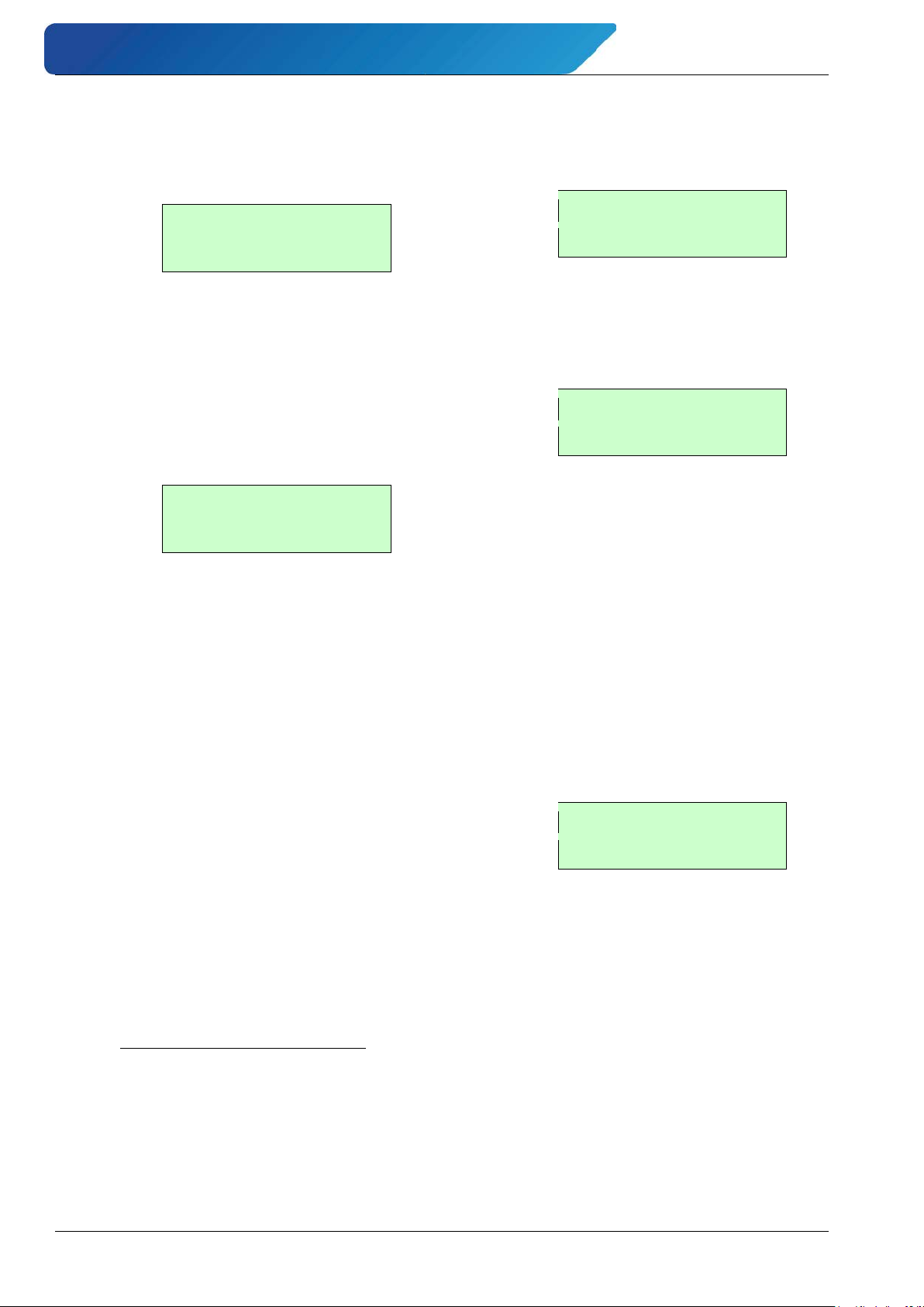
If you select the function totalizer re-
verse
, the current value of the totalizer re-
verse will be displayed.
Example:
The displayed unit is defined in the functional
class TOTALIZER using the function total-
izer unit
.
Flow velocity:
If you select the function flow velocity the
LCD shows the current value of the average
flow velocity of the medium.
Example:
The displayed unit is always meters per second (m/s).
The average velocity is calculated from the
measured volume flow and the cross section
of the meter tube. For the calculation of the
cross section, the inside diameter of the meter tube is needed.
It will be defined by the function inside di-
ameter
in the functional class SETTINGS
SENSOR + VMM“.
Relative flow rate:
The relative flow rate Qrel is the percentage
ratio of the (current) volume flow Qabs and the
upper range value of the volume flow.
If you select the function relative flow,
the following will be displayed.
Example:
QV + forward totalizer 1:
If the function QV totalizer 1 is selected,
in the first line the value of the forward totalizer 1 and in the second line the current value of the volume flow will be displayed.
Example:
The displayed unit for the volume flow is de-
fined in the functional class FLOW using the
function volume flow unit.
The unit of the totalizer is defined in the
functional class TOTALIZER using the function totalizer unit.
QV + forward totalizer 2:
This function is basically similar to the function QV°totalizer 1.
The only difference is that in the first line the
value of the forward totalizer 2 is displayed.
Example:
The calculation of the relative flow rate is
based on the following formula:
- 26 - © SIKA • Ba_VMM_us • 09/2018
Page 27
induQ
iiii:
Is a numeric value for the current
XXX.X USG/min
XXX.XX m/s
Display mode
[ QV ]
xxx.xxx ggooo
iiii gguuu
®
- Series VMM Operation
QV + flow velocity:
If the function QV+ flow velocity is selected,
in the first line current value of the volume
flow and in the second line the current flow
velocity will be displayed.
Example:
The displayed volume flow unit is defined in
the functional class FLOW using the function
volume flow unit, the unit of the flow velocity
is always m/s.
Display mode during startup:
By choosing the function display mode
during startup
the operator can define the
default display. This selected parameter will
be displayed after switching on the device
and when no keystroke occurs for a long period of time.
Example:
Raw value display:
The raw value display supports fault diagnostics and trouble shooting. Please inform
our service department about the clear text
error messages and content of the raw value
display.
Example:
The displayed values are decimals and have
the following meaning:
xxx.xxx: Is a numeric value for the meas-
ured electrode voltage.
to generate the field coil’s magnetic field.
ggooo: Is a numeric value for the upper
value of the reference calibration.
gguuu: Is a numeric value for the lower
value of the reference calibration.
7.1.2 Password
One of the following default parameters can
be selected:
• QV (volume flow rate),
• totalizer 1 forward flow,
• totalizer 2 forward flow,
• totalizer R(reverse flow),
• velocity,
• QVabs + QVrel,
• QV + totalizer 1,
• QV + totalizer 2,
• QV + velocity,
• raw values.
How to change the parameter please refer to
Section "Selection window / make a selection".
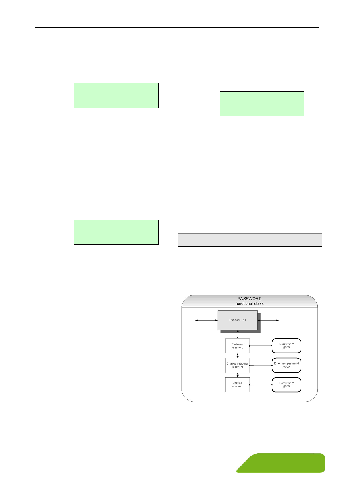
The PASSWORD functional class includes the
functions for entering and changing the customer password and entering the service
password.
To discard the changes, press Esc.
Technical changes reserved - 27 -
Page 28
Operation induQ
Password?
0000
Password
valid
Password
invalid
New Password?
0000
®
- Series VMM
Customer password:
The customer password is intended to prevent changes for software parameters of the
VMM by the control unit without permission.
If the operator does not enter a valid password, all settings can be displayed but not
changed.
For selecting the desired function please use
the key and .
After selecting the function Change customer password and pressing ENTER key, the
operator enters the parameter level for
changing the customer password.
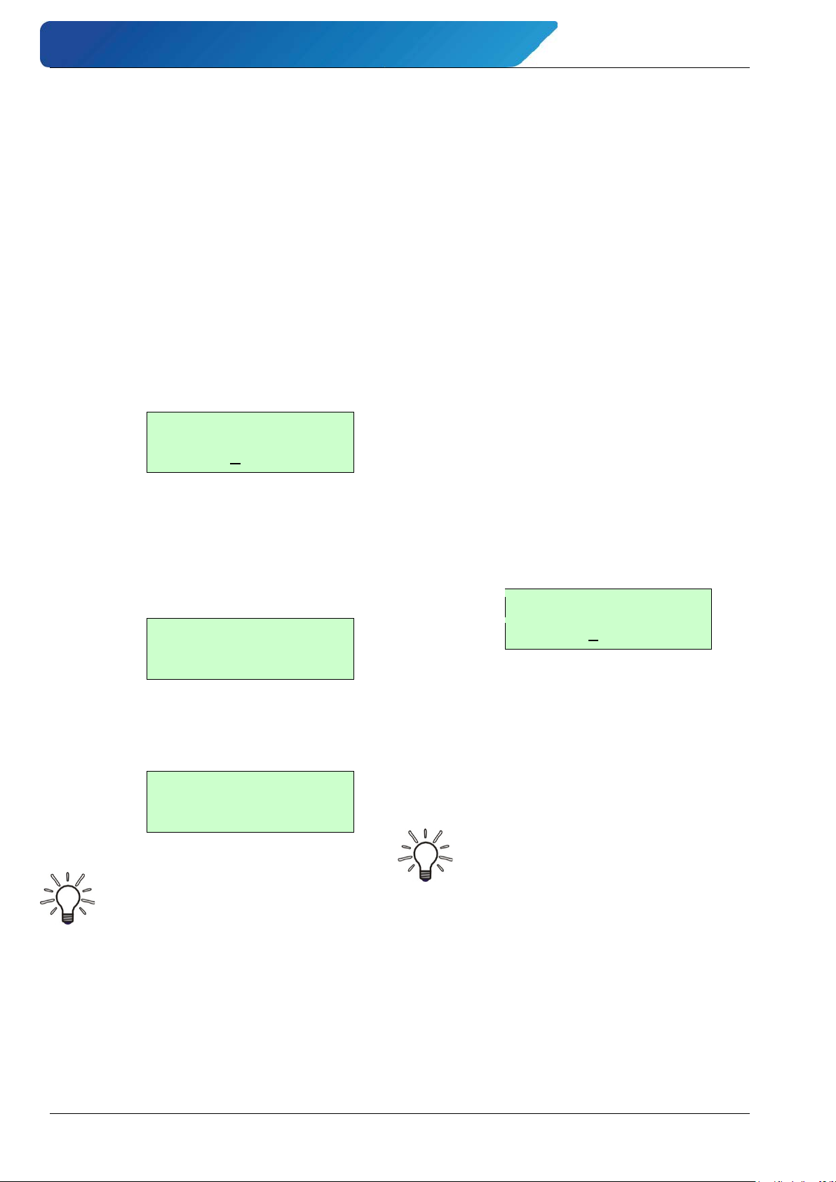
The following will be displayed:
The password can be changed according to
the description in section "Input window /
modify a value".
After entering a valid password, the following
message will be displayed:
If the entered password is not correct, the
following message will be displayed:
A valid customer password allows changes
for all software parameters that are permissible for customers.
After the operator switched off the device or
no keystroke occurs for about 15 minutes,
the authorization for changes are cancelled
and the password must be entered again.
Change customer password:
After entering a valid customer password,
you may change the existing password and
enter a new one.
The prerequisite for this is the previous, correct entry of the currently valid customer
password.
For selecting the desired function please use
the key and .
After selecting the function Change cus-
tomer password and pressing ENTER key,
the operator enters the parameter level for
changing the customer password.
The following will be displayed:
According to the description in Section "Input
window / modify a value" the changes can be
done.
Press ENTER key to confirm and save the
new password.
Notice
The factory set for the customer
password is 0002.
Notice
A copy of the password should be kept
in a safe place. Reactivation of a display electronics at the vendor’s site
due to a lost password is not part of
our warranty!
- 28 - © SIKA • Ba_VMM_us • 09/2018
Page 29
induQ
Mass units*
kg
Kilogram
Totalizer unit
[ USG ]
®
- Series VMM Operation
Service password:
The service password is not required for parameter settings which are relevant for operation.
The service password is reserved for service
technicians and not provided to customers.
7.1.3 Totalizer
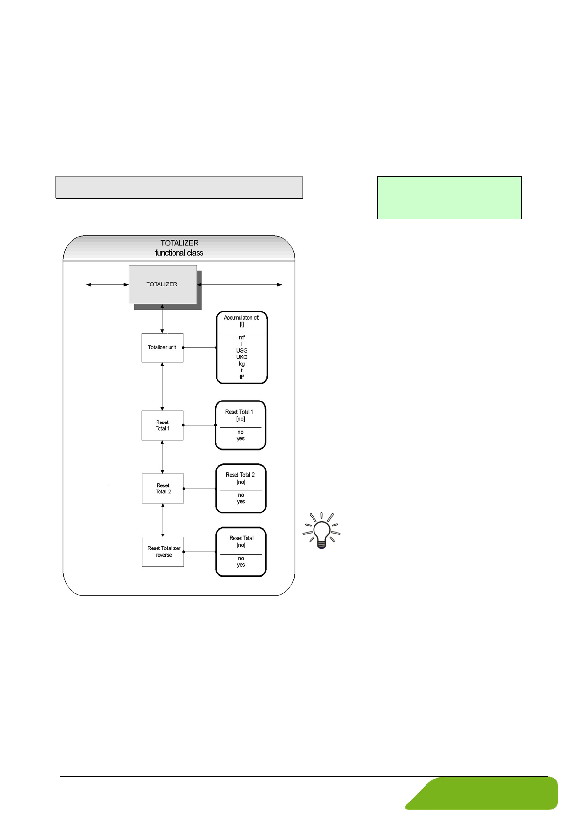
The TOTALIZER functional class includes the
following functions:
Totalizer unit:
For selecting the desired function please use
the key or .
After choosing the function Totalizer
unit and pressing ENTER key, the current
forward and reverse totalizer unit will be
displayed.
Example:
How to change the parameter please refer to
Section "Selection window / make a selection".
The following units are available:
Volume units m3 Cubic meter
l Liter
USG Gallon (US)
For changing the current settings and parameters the customer password is needed.
Otherwise, the settings only can be watched
but not be changed.
The ESC key is used for discarding changes.
UKG Gallon (brit.)
ft3 Cubic feet
t Tonne
* When selecting a mass unit the liquid density is
certainly required ( "Flow", p. 31).
The changes will be confirmed by pressing
the ENTER key and the new unit will be active as well for the forward totalizers and the
reverse totalizers.
Notice
When the unit is changed, the totalizers will be reset to 0.00 automatically!
Totalizer reset:
The display electronics of the VMM has three
independent totalizers.
Totalizer 1 and Totalizer 2 for the forward
flow and a totalizer for reverse flow.
Technical changes reserved - 29 -
Page 30
Operation induQ
τ
Reset total?
[yes]
Damping
03 s
®
- Series VMM
Each of them can be reset individually to the
initial value 0.00.
In the first step the required totalizer has to
be chosen by using the or key.
After the confirmation with the ENTER key,
the function Reset totalizer must be selected and the following will be displayed:
To reset one of the totalizers, you need to
toggle to [yes] explicitly ( "Selection window / make a selection", p. 23).
By pressing Esc or toggling to [no] the current action will be aborted without changing
the totalizer.
7.1.4 Measurement processing
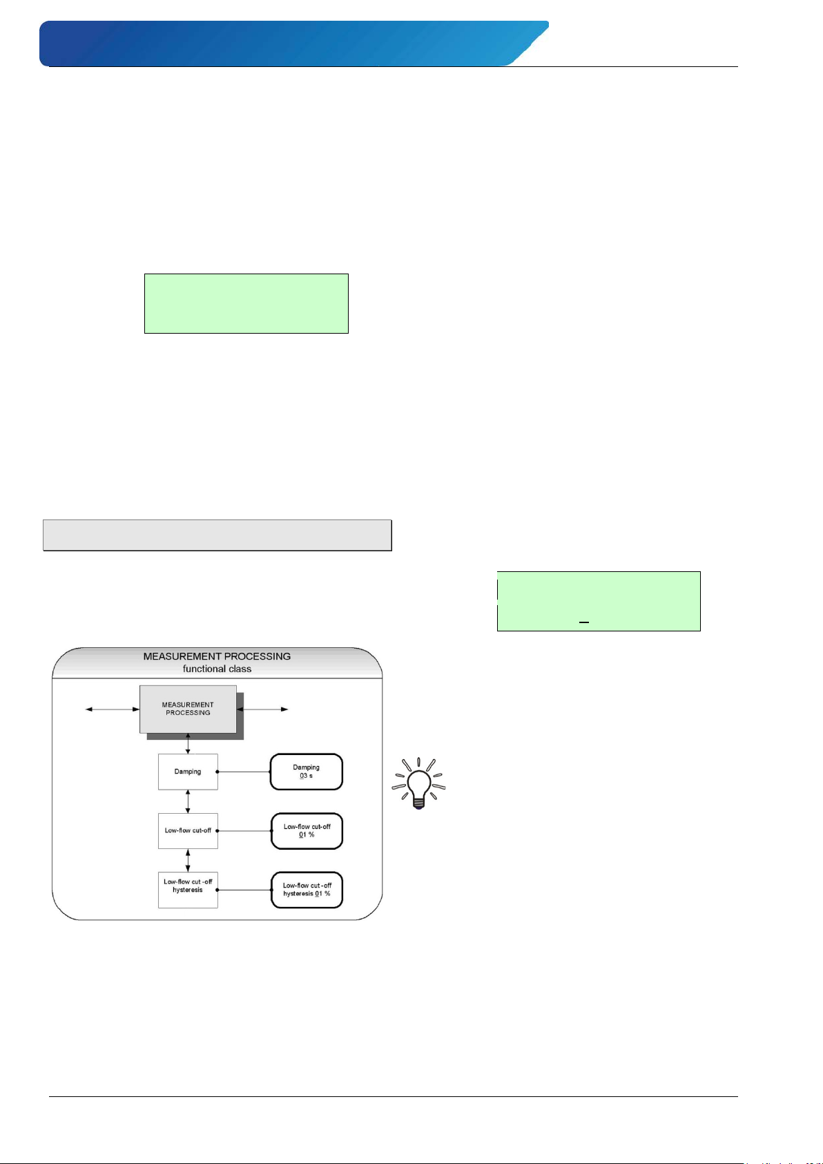
The MEASUREMENT PROCESSING functional
class includes all functions that affect the
processing of the measured values.
Before changing the current settings, the
customer password has to be entered.
Otherwise, the settings only can be watched
but not changed.
The ESC key is used for discarding changes.
Damping value:
The damping value
is intended to attenuate
abrupt changes of the flow rate or disturbances.
It affects as well the display of the measured
value as the current output and pulse output
of the VMM.
For selecting the desired function within a
functional class please use the key and .
By choosing the function Damping value
and pressing Enter, the parameter level is
entered and the current value for the damping is displayed:
Example:
The damping value can be varied within an
interval from 1 to 60s ( "Input window /
modify a value", p. 23).
Notice
After a jump in the measuring variable
the output measured value reaches
about 99% of the new set point after
5τ.
The factory setting is 3 seconds.
- 30 - © SIKA • Ba_VMM_us • 09/2018
Page 31
induQ
Low flow cut
00 %
Low flow cut
hysteresis 0.0 %
®
- Series VMM Operation
Low flow cut:
The low flow cut is a threshold for flow
rate (percentage the upper-range value).
If the volume drops below this value, the displayed value and the current outputs will be
set to “ZERO.”
For selecting the desired function please use
the key or . After choosing the function
Low flow cut and pressing Enter, the fol-
lowing selection field will be displayed.
Example:
The value for low flow cut can be set from 0
to 20 % in 1-percent increments.
Hysteresis for the low flow cut:
The value for hysteresis for the low flow cut
is given as a percentage of the upper-range
value. It is the flow rate, the low flow cut has
to be exceeded, to activate the display and
the outputs.
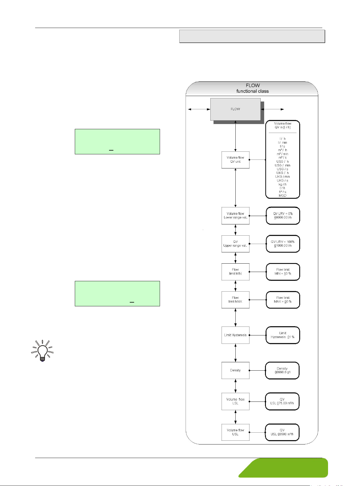
7.1.5 Flow
The FLOW functional class includes functions that affect lower- and upper-range values and the processing of the measured flow
rates.
For selecting the desired function please use
the key or . After selecting the function
Low flow cut hysteresis and pressing
Enter, the following selection field will be
displayed.
Example:
The hysteresis for the low flow cut can be set
from 0 to 10 % in 1-percent increments.
Note
When the creep rate is exceeded, the
analog output is set to 0/4 mA and no
pulses are output on the pulse output.
Technical changes reserved - 31 -
Page 32
Operation induQ
Volume units:
m3 / s
m3 / min
m3 / h
l / s
l / min
l / h
USG / s
USG / min
USG / h
UKG / s
UKG / min
UKG / h
ft3 / s
MGD
(Mega US Gallons /
day)
Mass units*:
kg / h
t / h
Volume flow QV
in [USG/min]
QV LRV = 0%
+0.000000 USG/min
®
- Series VMM
Before changing the current settings, the
customer password has to be entered.
Otherwise, the settings only can be watched
but not changed.
The ESC key is used for discarding changes.
Volume flow QV unit:
Using this function, the physical unit, limit
values and the upper-range value of volume
flow can be defined.
For selecting the desired function please use
the key or . After choosing the Volume
flow QV unit
function and pressing the
ENTER key, the following selection field will
be displayed.
Example:
For changing the parameter please refer to
the description in Section "Selection window
/ make a selection".
The following units are available:
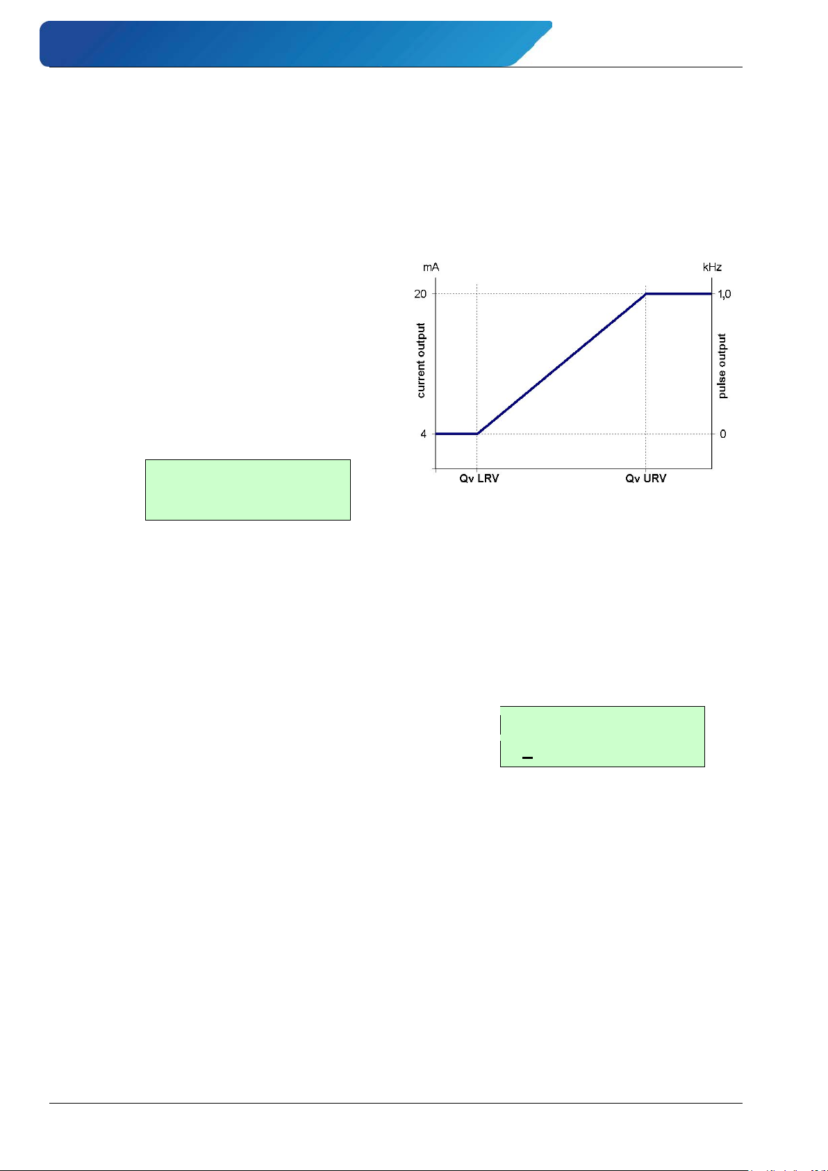
7.1.5.1 Scaling the outputs
The measuring variable volume flow rate is
shown by the VMM as well as an analog current output as a pulse output.
The correlation of output and flow rate is not
fixed but it can be defined by the parameters
QV LRV and QV URV (see Fig).
Volume flow lower-range value:
This function allows setting the lower-range
value for volume flow QV LRV which corresponds to the lower-range value for the output value.
For selecting the desired function please use
the key or . After choosing the function
Volume flow lower-range value and
pressing Enter, the following selection field
will be displayed:
Example:
* When selecting a mass unit the liquid density is
certainly required.
- 32 - © SIKA • Ba_VMM_us • 09/2018
The unit for the QV LRV is defined by the
function Volume flow unit.
Usually the value for QV LRV is set to 0.0
(factory default).
Volume flow upper-range value:
This function is intended to set the upperrange value for volume flow QV URV which
corresponds to the upper-range value for the
output value.
Page 33
induQ
QV URV = 100%
+00005.00 USG/min
Flow limit
MIN = 10 %
Flow limit
MAX = 090 %
QV limit
hysteresis 00 %
®
- Series VMM Operation
After choosing the function Volume flow upper-range value and pressing the ENTER
key, the following selection field will be displayed.
Example:
The unit for the QV URV is defined by the
function Volume flow unit.
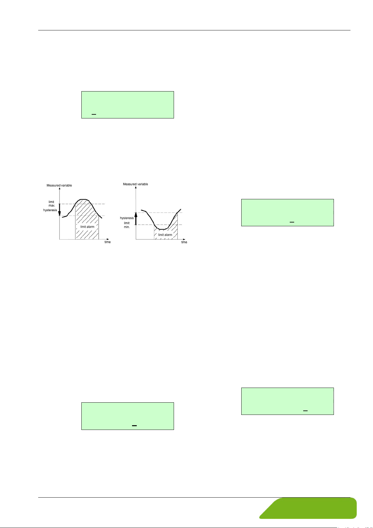
7.1.5.2 Limit value messages
Fig: Limit value message and hysteresis.
Volume flow limit MIN:
The MIN limit value for volume flow can be
shown by the status output.
The value for volume flow limit MIN is
a percentage of the current measuring range
(lower-range value QV LRV to upper-range
value QV URV). If the volume flow falls below
that limit, the status output will be set and
the current output will change to alarm value, if the alarm functions have been enabled
(see Fig above).
For selecting the desired function please use
the key or . After choosing the function
Volume flow limit MIN and pressing En-
ter, the following selection field will be displayed.
Example:
The value can be set in 1-percent increments.
Volume flow limit MAX:
The MAX limit value for volume flow can be
shown by the status output.
The value for volume flow limit MAX is a percentage of the current upper-range value QV
URV. If the volume flow surpasses this limit,
the status output will be set and the current
output will change to alarm value, if the
alarm functions have been enabled (see Fig
above).
For selecting the desired function please use
the key or . After choosing the function
Volume flow limit MAX and pressing En-
ter, the following selection field will be displayed:
Example:
The value can be set in 1-percent increments.
QV limit hysteresis:
The value for Qv limit hysteresis is a percentage of the current upper-range value QV
URV. It specifies the difference between the
flow rate and the set volume flow limits
which is needed to reactivate respectively
deactivate the limit alarm.
For selecting the desired function please use
the key or . After choosing the function
QV limit hysteresis and pressing the ENTER
key, the following selection field will be displayed.
Example
The value can be set in 1-percent increments
from 0 to 10 %.
Technical changes reserved - 33 -
Page 34
Operation induQ
Density
0998.2 g/l
QV LSL
+0330.000 USG/min
QV USL
+15764.0 USG/min
®
- Series VMM
Density:
If a mass unit in kg or t is used as flow unit,
the density of the medium must be entered
in [g/l]. The mass flow will be calculated
from the volume flow measurement using
the density.
After choosing the function Density and
pressing Enter, the current density value will
be displayed:
Example:
The density can be entered precise to 0.1 g/l.
Notice
The density is not measured. It is a parameter.
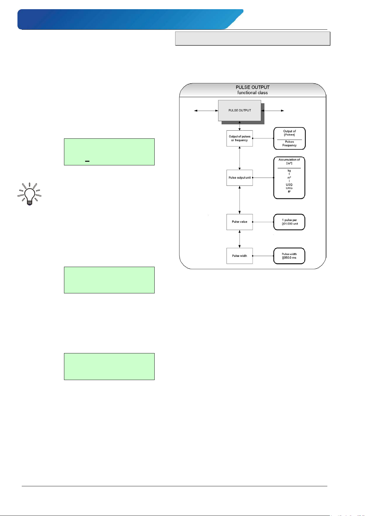
7.1.6 Pulse output
The PULSE OUTPUT functional class includes the functions regarding the pulse
output.
Volume flow LSL (read only):
This value represents the minimum lower
range value based on the inside diameter of
the sensor. This value is normally set for a
flow velocity of 0.82 ft/s (0.25 m/s).
Example:
Volume flow USL (information field):
This value represents the maximum upper
range value based on the inside diameter of
the sensor. This value is normally set for a
flow velocity of 36 ft/s (11 m/s).
Example:
The function Pulse or frequency output
is used to define the mode for the digital output – either pulses per flow unit or a frequency 0 to 1 kHz corresponding to the
measuring range.
7.1.6.1 Frequency output
When selecting „frequency”, the maximum
frequency of 1 kHz will be output when the
upper-range value for mass or volume flow
QV URV is reached (depending on the selected pulse unit). If the flow rate falls below the
volume flow limit MIN, the frequency is set to
0 Hz.
7.1.6.2 Pulse output
When selecting „pulses”, pulses per flow unit
will be output by the transmitter. The pulse
shape is defined by the parameters pulse
output unit, pulse value and pulse width.
- 34 - © SIKA • Ba_VMM_us • 09/2018
Page 35
induQ
Pulse width
inconsistent
too large
parameters
Volume units:
m3
Cubic meter
l
Liter
USG
Gallon (US)
UKG
Gallon (brit.)
ft3
Cubic feet
Mass units:
kg
Kilogram
t
Tonne
1000Hz
[ms] width pulse2
1
≤
⋅
=
f
Output of
[pulses]
Accumulation
of [ USG ]
1 pulse per
001.000 unit
Pulse width
0050.0 ms
®
- Series VMM Operation
When choosing an improper combination of
these parameters (e.g. the number of pulses
per time unit cannot be generated due to the
pulse width which is too large), one of the
following error messages will be displayed:
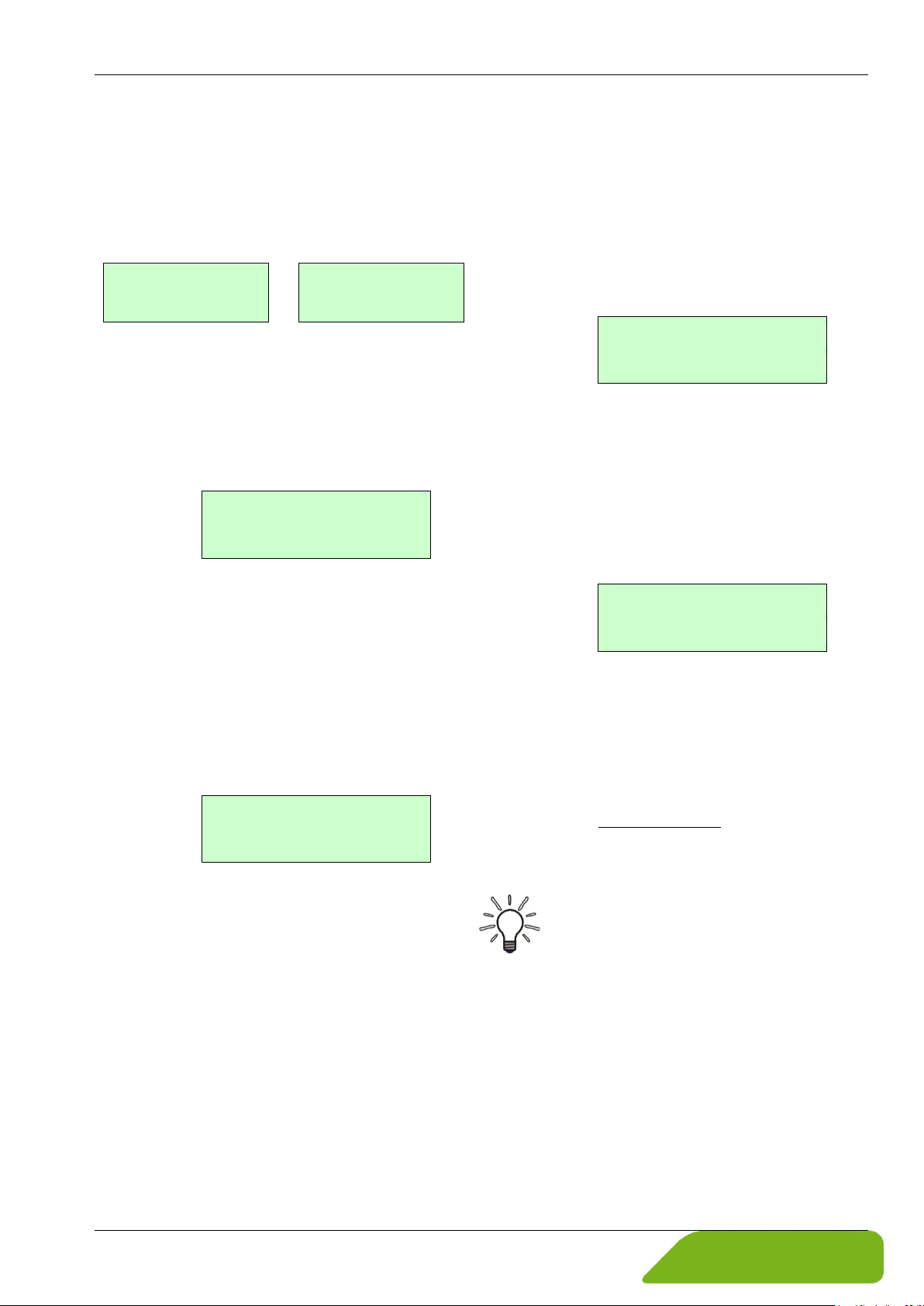
For selecting the desired function please use
the key or . After choosing the function
output of pulses or frequency and
pressing Enter, the following selection field
will be displayed.
Example:
Pulse output unit:
This function is used to define the unit to be
accumulated.
After selecting the function Pulse output
unit, press Enter to enter the parameter level. The following selection field will be displayed:
Example:
For this parameter the following units are
available:
Pulse value:
This function is used to define how many
pulses will be output per accumulated unit.
After selecting the function Pulse value,
press the ENTER key to display the current
unit:
Example:
Pulse width:
This function is intended to change the width
of the pulses.
For selecting the desired function please use
the key or . After selecting the function
Pulse width, press Enter to display the actual
setting for this parameter:
Example:
If the pulse width for the actual pulse number is selected too high, the warning message "Value too high" appears and the
changes are not applied.
The maximum output frequency f can be calculated by
Notice
For connection of electronic counters,
we recommend a pulse width greater
than 4 ms; for electromechanical
counters the value should be 50 ms.
Technical changes reserved - 35 -
Page 36
Operation induQ
Setting
Function
closed
Status output operates like break
contact
opened
Status output operates like make
contact
Detection of flow direction:
Forward flow
Reverse flow
Limit values:
MIN Qrel
MAX Qrel
All limit values and error detection:
Alarm
Output active
[closed]
Assignment
to [Reverse flow]
®
- Series VMM
7.1.7 Status output
The functional class STATUS OUTPUT includes the functions for setting the status
output.
Status output active state:
The function Status output active state
is intended to define the behavior of the status output.
The status output is comparable to an electrical relay that can be configured as make
or break contact.
As mentioned in "Selection window / make a
selection", one of the following settings can
be chosen.
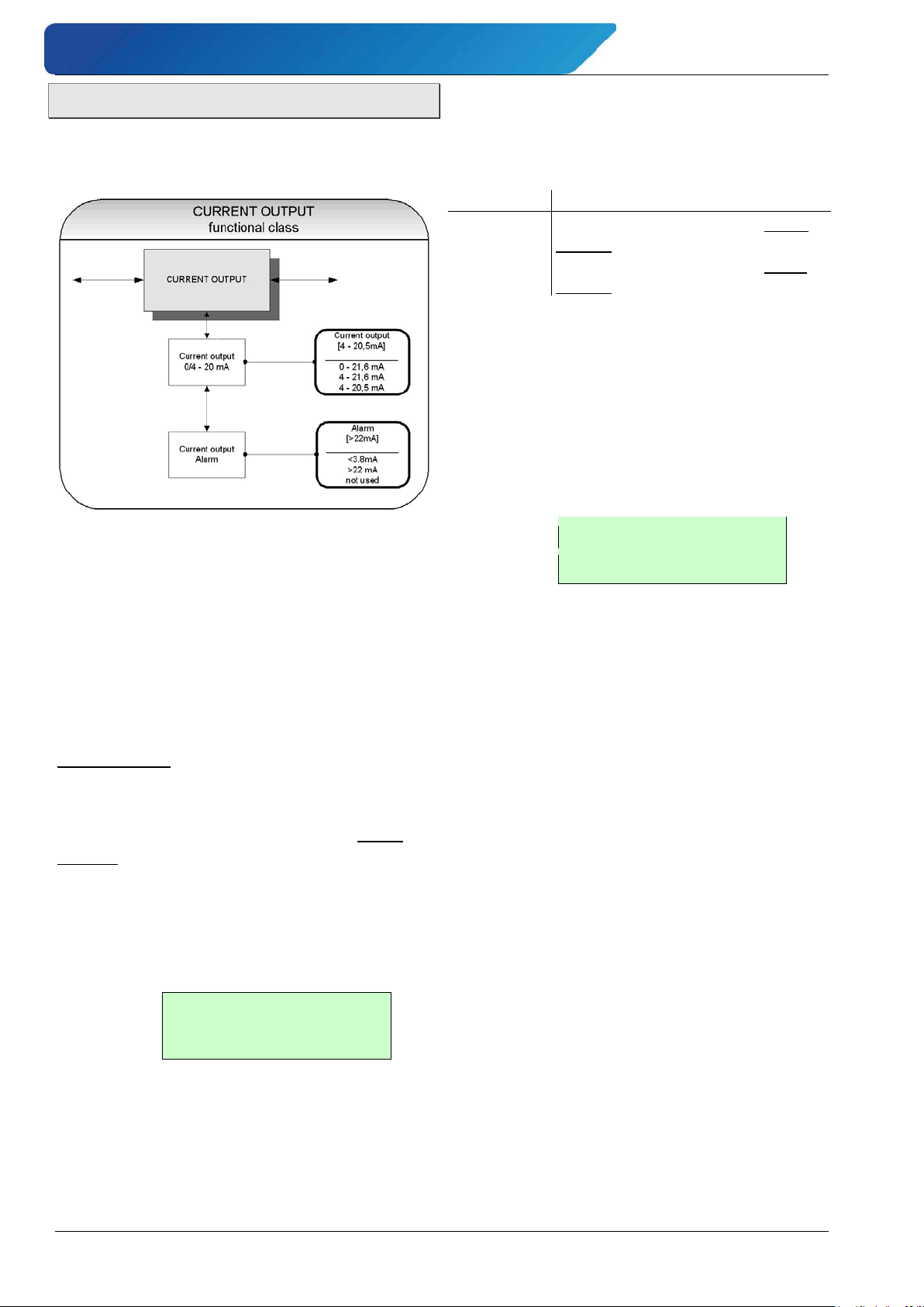
Status output assignment:
This function allows the operator to define
the event assignment for the status output.
For selecting the desired function within the
class please use the keys and . After selecting the function Status output assignment, press Enter, the current setting will be
displayed:
Example:
As mentioned in Section "Selection window /
make a selection" one of the following settings can be chosen:
For safety-relevant applications, the setting
break contact is highly recommended so that
a power failure or failure of the electronics
can be detected as an alarm.
In standard applications, the setting make
contact is usually used.
For selecting the desired function please use
the key or . After selecting the function
Status output state active state,
press the ENTER key to display the current
setting:
Example:
The default setting is reverse flow.
- 36 - © SIKA • Ba_VMM_us • 09/2018
Page 37
induQ
Current output
[4–21.6] mA
Alarm
[ >22 mA ]
®
- Series VMM Operation
7.1.8 Current output
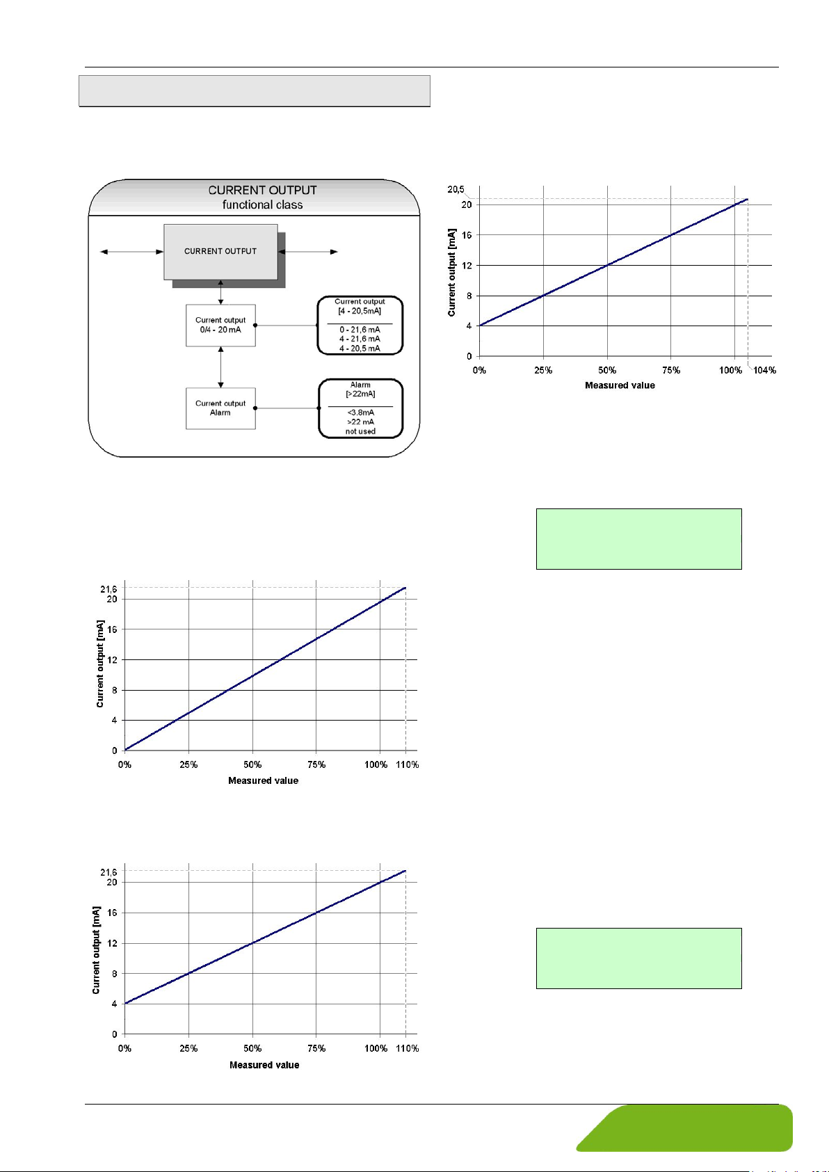
The CURRENT OUTPUT functional class includes the settings for the current outputs of
the display electronics.
The current output is generally assigned to
volume flow.
The range from 4 to 20,5 mA is according to
the NAMUR-recommendation and uses the
measuring range up 104%.
For selecting the desired function within the
class please use the keys and .
After selecting the function Current output
0/4 – 20 mA
, press the ENTER key to dis-
play the current setting:
Current output 0/4 - 20 mA:
This function is intended for defining the operating range for the current output.
The standard range from 4 to 21.6 mA uses
the measuring range up to 110 %.
Example:
One of the following settings can be chosen
( "Selection window / make a selection",
p. 23):
• 0 – 21.6 mA
• 4 – 21.6 mA
• 4 – 20.5 mA
Current output alarm:
This function is intended for defining the
state for the current output when an alarm
state occurs. This information can be analyzed in the process management system.
For selecting the desired function within the
class please use the keys and .
After selecting the function Current output
alarm
, press the ENTER key to display the
current setting:
Technical changes reserved - 37 -
Example:
Page 38
Operation induQ
Simulation
[off]
Preset of
[direct]
®
- Series VMM
One of the following settings can be chosen
( "Selection window / make a selection",
p. 23):
Setting Function
not used no alarm function
>22 mA rise of current in case of alarm
<3,8 mA reduction of current in case of
alarm
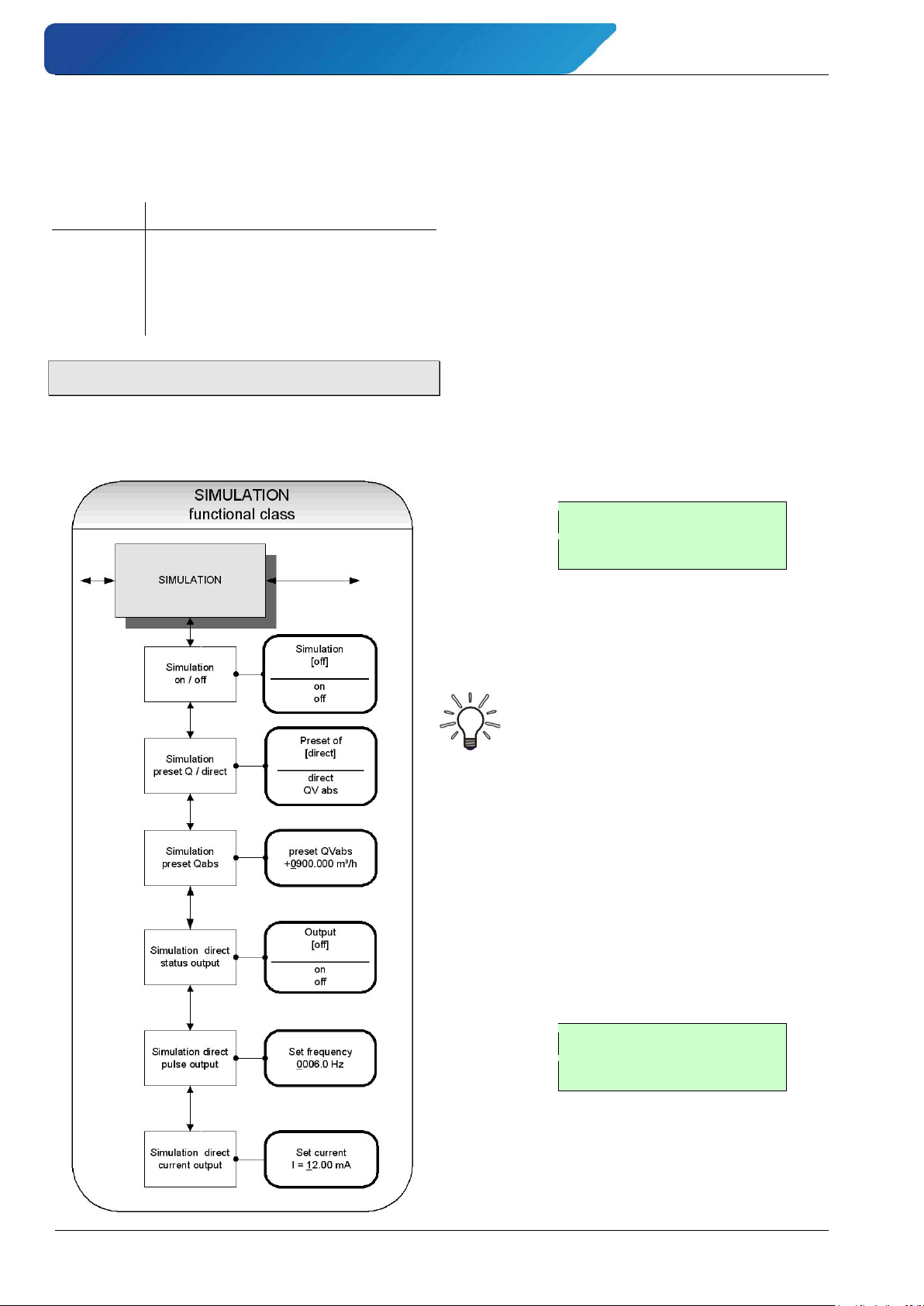
7.1.9 Simulation
The functional class SIMULATION includes
the functions for simulating output signals or
output states.
If simulation mode is activated, all output
signals will be generated depending on the
selected items. This function enables testing
of peripherals connected to the device without water flow.
Simulation on / off:
The function Simulation on/off is intended for activating or deactivating simulation mode
For selecting the desired function within the
class please use the keys and .
After selecting the function simulation
on/off,
press the ENTER key to display the
current setting:
Example:
For changing the parameter please refer to
the description in Section "Selection window
/ make a selection".
Notice
Simulation will be deactivated automatically after restarting the device or
without a keystroke for at least 10
minutes.
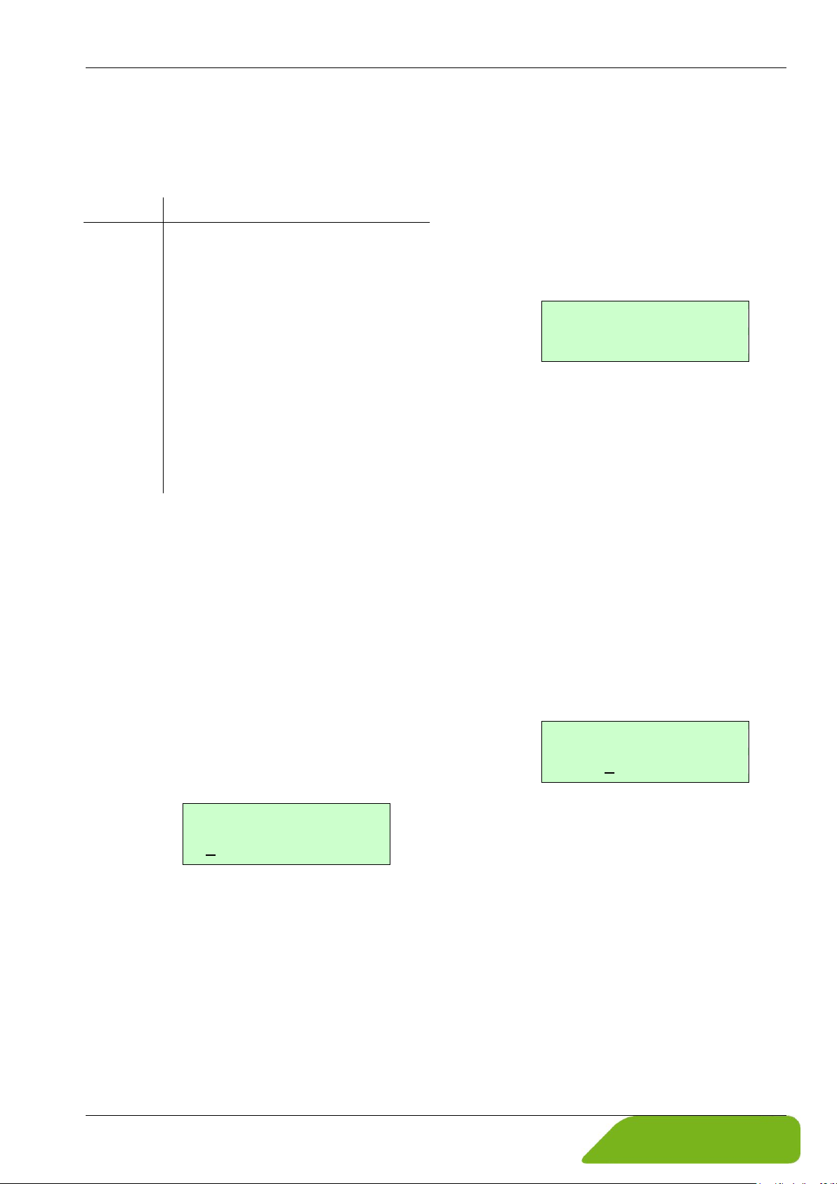
Simulation preset value Q / direct:
This function is intended for defining whether
a volume flow rate is preset or the outputs
will be set directly.
For selecting the desired function within the
class please use the keys and .
Press ENTER key to display the current selection for the type of simulation:
Example:
- 38 - © SIKA • Ba_VMM_us • 09/2018
Page 39
induQ
Setting
Function
direct
neously!
QVabs
The measuring variable will be set
Preset Q
+00004.00 USG/min
Output
[off]
Set frequency
0210 Hz
®
- Series VMM Operation
One of the following settings can be chosen
( "Selection window / make a selection",
p. 23):
Status-, pulse-, und current output* will be set directly
* It is useful to make the presets for
the outputs before starting simulation mode, using menu items Simu-
lation status output, Simulation pulse output and
Simulation current output.
In this manner the settings can be
modified specifically.
All outputs will be simulated simulta-
Simulation preset Q*:
Using this function a „measuring variable” is
preset for simulating a flow rate. Flow rates
for both directions will be supported. The
outputs will be affected by the simulated value for the measured value indirectly.
For selecting the desired function within the
class please use the keys and .
After selecting the function Simulation
preset Q
, press the ENTER key to enter the
parameter level for putting in the requested
value:
Example:
The simulation value is entered as described
in Section "Input window / modify a value".
* This parameter Preset Q is of relevance only,
if the parameter Simulation preset Q /
direct is set to "QVabs".
Direct simulation – status output *:
Using the function Simulation direct
status output
the status output can be af-
fected directly.
For selecting the desired function within the
class please use the key or .
After selecting the function Simulation di-
rect status output
, press the ENTER key.
The current setting will be displayed:
Example:
For changing the parameter please refer to
the description in Section "Selection window
/ make a selection".
* This parameter is of relevance only, if the para-
meter preset of is set to „direct“.
Direct simulation – pulse output *:
Using the function Simulation direct
pulse output
the requested frequency for
the pulse output can be defined.
For selecting the desired function within the
class please use the key or .
After selecting the function Simulation direct
pulse output, press the ENTER key. The current value for the frequency will be displayed:
Example:
The frequency can be set within bounds of
6 Hz to 1100 Hz
For changing the parameter please refer to
the description in Section "Input window /
modify a value".
* This parameter is of relevance only, if the
parameter preset of is set to „direct“.
Technical changes reserved - 39 -
Page 40
Operation induQ
Set current
I = 12.50 mA
®
- Series VMM
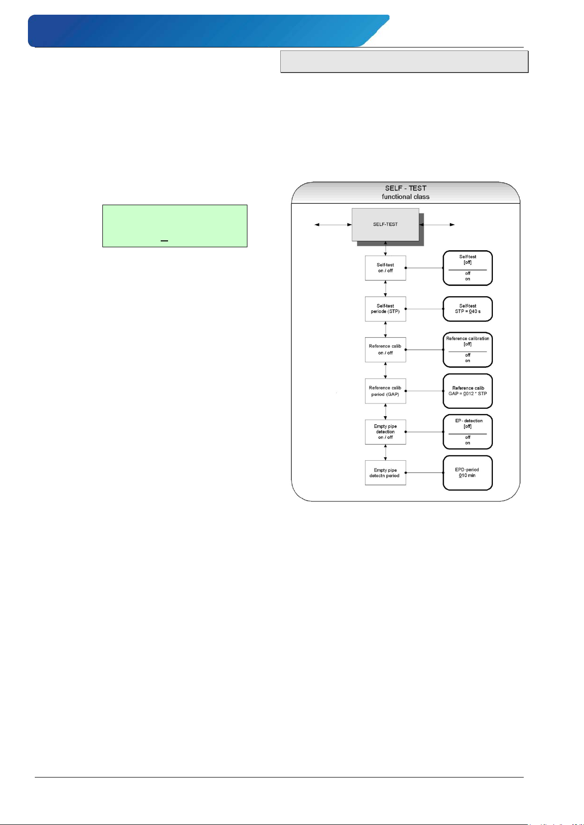
Direct simulation – current output *:
Using this function the requested value for
the current output can be defined.
For selecting the desired function within the
class please use the key or .
After selecting the function Simulation di-
rect current output
, press the ENTER
key. The actual value for the current will be
displayed:
Example:
The current can be set within bounds of 0 to
23 mA. For changing the parameter please
refer to the description in Section "Input
window / modify a value".
* This parameter is of relevance only, if the pa-
rameter preset of is set to „direct“.
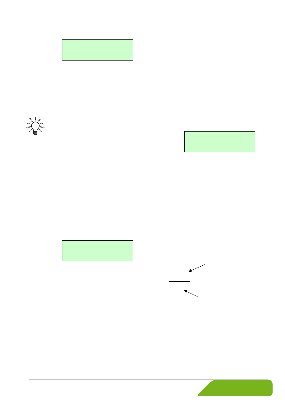
7.1.10 Self-test
The function class SELF-TEST includes all
functions relating to the self-test of the sensor. The diagnostic functions of the display
electronics, which monitor the signals of the
sensor and proper functioning of the electronics and the software, are always active
and cannot be switched off.
Self-test on / off:
The Self-test on/off function is intended
for enabling or disabling the monitoring
function of the field coil current. This function is useful for suppressing temperature
dependencies of the display electronics.
After selecting the function Self-test
on/off
using the key or press the
ENTER key. The current setting will be displayed.
- 40 - © SIKA • Ba_VMM_us • 09/2018
Page 41
induQ
5400
40s
3600s6
GAP =
⋅
=
Self-test
[off]
Self-test
STP = 040 s
Reference calib.
[off]
Self-Test period STP
1 hour = 3600 s
®
- Series VMM Operation
Example:
The default setting for the monitoring function for the field coil current is „on“.
For changing the parameter please refer to
the description in Section "Selection window
/ make a selection".
Notice
During the sampling time for the field
coil current of 0.5 seconds, the transmitter is offline. The last measured
value will be shown at the signal outputs.
Self-test period (STP)*:
Using this function the time gap for the periodical measurement of the field coil current
is defined.
The time gaps can be set within bounds of 35
to 999 s.
After selecting the function Self-test period
(STP) using the key or , press the
ENTER key for entering the parameter level.
The current setting for the STP will be displayed:
Example:
For changing the parameter please refer to
the description in Section "Input window /
modify a value".
* The parameter Self-test period (STP) is of
relevance only, if the parameter
set to „on“.
Self-test is
Reference calibration on / off:
The function Reference calibration
on/off
is used to enable or disable the periodical recalibration of the transmitter. This
function is useful for periodical selfmonitoring and for maintaining the longterm stability of the display electronics.
After choosing the function Reference cal-
ibration on/off
by the use of key or
and pressing Enter, the following selection
field will be displayed:
Example:
For changing the parameter please refer to
the description in Section "Selection window
/ make a selection".
Reference calibration period (GAP):
This function Reference calibration pe-
is used to define after how many STPs
riod
the reference calibration will be performed.
Example:
The Self-Test period (STP) is set to 40 seconds. The reference calibration should be
performed every 6 hours. Therefore you have
to enter for the GAP:
For selecting the desired function within the
class please use the key or .
Technical changes reserved - 41 -
After selecting the function Reference cal-
ibration period (GAP)
using the key
or press the ENTER key. The current set-
ting for this parameter will be displayed:
Page 42
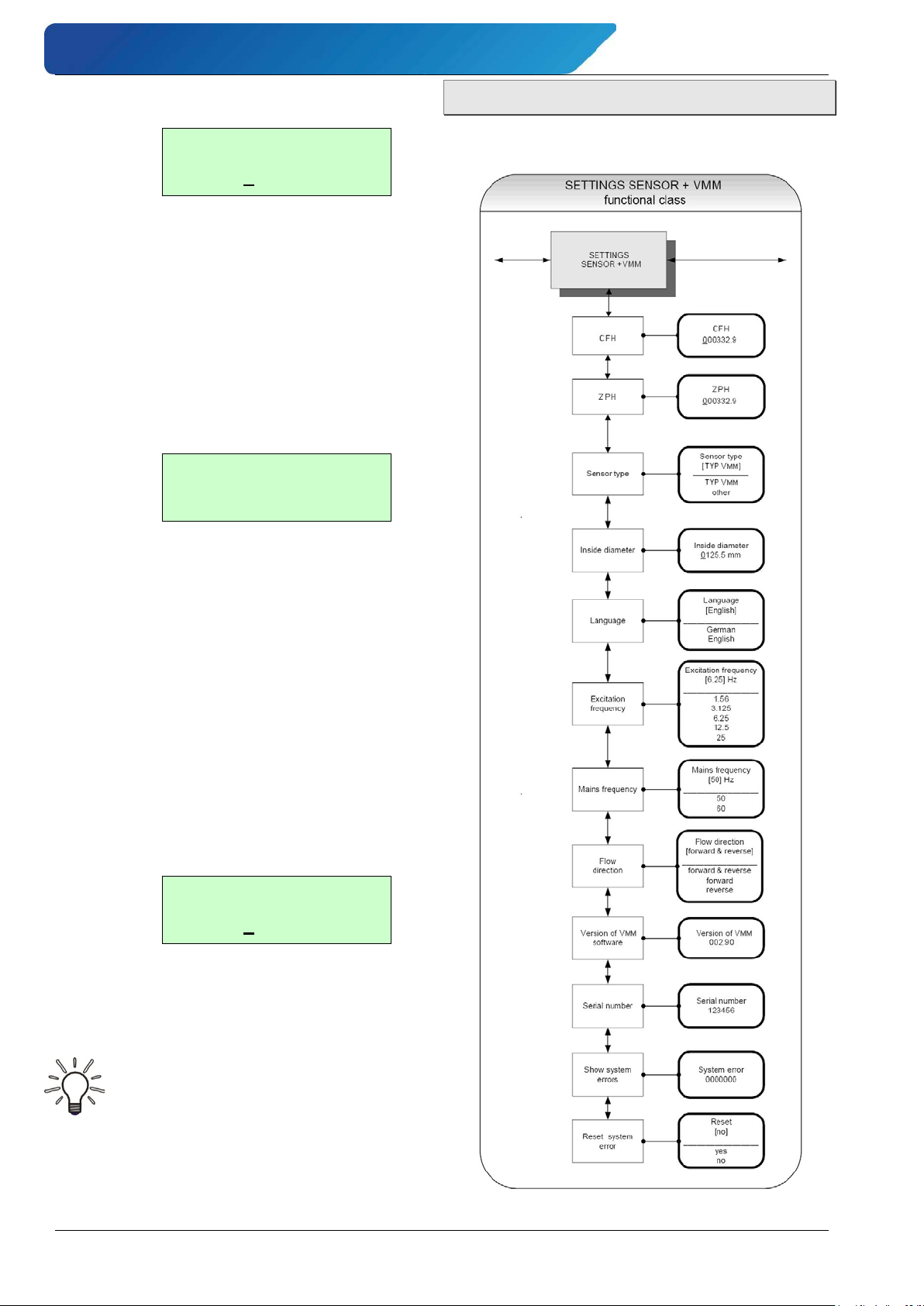
Operation induQ
Reference calib.
GAP=05400* STP
EP detection
[on]
EPD-period
10 Min
®
- Series VMM
Example:
For changing the parameter please refer to
the description in section "Input window /
modify a value".
Empty pipe detection on / off:
The function Empty pipe detection on /
off
, is used for enabling or disabling the
continuous empty pipe detection.
After selecting this function by the use of key
or and pressing Enter, the following selection field will be displayed:
Example:
The default setting for this parameter is
„on“.
7.1.11 Settings Sensor
This functional class SETTINGS SENSOR + VMM
includes the general settings for the device.
For further information how to change the
parameter please refer to the description in
section "Selection window / make a selection".
Empty pipe detection period:
The function Empty pipe detection peri-
od
, is intended for defining the period of time
after which the empty pipe detection will be
regularly carried.
After choosing this function using the key
or and pressing Enter, the following se-
lection field will be displayed:
Example:
For changing the parameter please refer to
the description in Section "Input window /
modify a value".
Notice
When entering 00 Min for this parameter, the detection will be performed
continuously.
- 42 - © SIKA • Ba_VMM_us • 09/2018
Page 43
induQ
CFH
0332.90
Sensor type
[TYP VMM]
Inside diameter
0050 mm
Language
[English]
®
- Series VMM Operation
Sensor constant CFH:
The sensor constant CFH is determined by
calibration and it’s a characteristic value for
the sensor.
The value for CFH must be entered to ensure
a correct measurement. It will be found on
the rating plate of the sensor.
After selecting the function Sensor con-
stant
function using the key or and
pressing Enter, the parameter level will be
entered and the actual value for sensor constant CFH will be displayed.
Example:
CAUTION! Measuring errors!
Changing the sensor constant CFH to
a value that differs from the value on
the rating plate of the sensor will result in measuring errors!
Note
The CFH value is signed. If the inlet
and outlet are mixed up during installation (the flow of direction is marked
on the sensor with an arrow), the display electronics displays negative
measurement values in the "Supply".
A positive value is displayed again by
changing the sign of the CFH value.
No changes to the electrical cable
connections are required.
Sensor type:
The function Sensor type is intended for defining the type of sensor which is connected
to the display electronics. The distinction of
the sensor type is necessary and essential
because the algorithm for flow rate calculation differs from sensor type to sensor type.
After selecting this function using the key
or and pressing Enter, the current setting
will be displayed:
Example:
This parameter is factory-set and it has to be
changed only when the transmitter is used
with a different type of sensor.
Inside diameter:
The inside diameter of the connected sensor
is needed for calculating the mean flow velocity. To ensure a correct measurement the
diameter must be specified exactly.
After choosing the function inside diameter
using the key or and pressing Enter,
the following selection field will be displayed.
Example:
For changing the parameter please refer to
the description in Section "Input window /
modify a value".
Language:
English and German are available for the user guidance of the VMM.
The function Language is intended for setting
the language.
After choosing the desired function using the
key or and pressing Enter, the following selection field will be displayed:
Example:
For changing the parameter please refer to
the description in Section "Input window /
modify a value".
Technical changes reserved - 43 -
Page 44
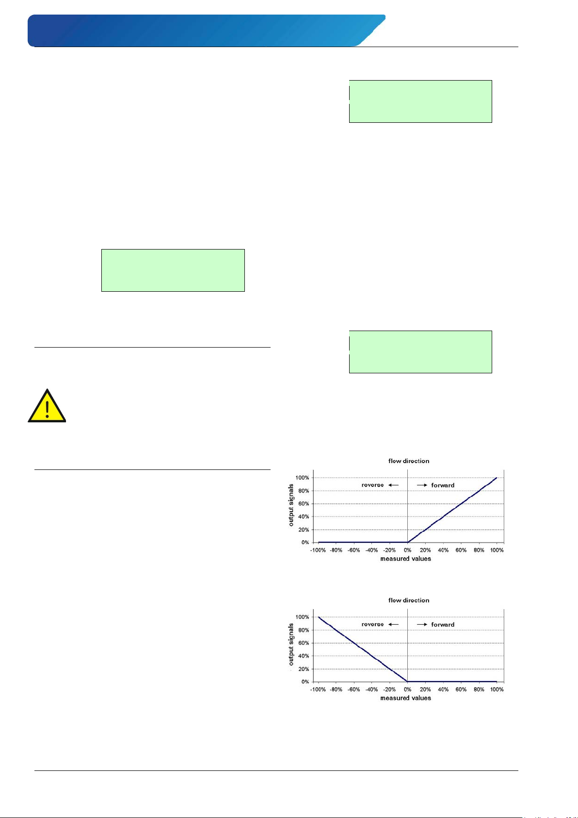
Operation induQ
Excitation freq.
[6.25Hz]
Mains frequency
[60] Hz
Flow direction
[forward]
®
- Series VMM
Excitation frequency:
The function Excitation frequency is intended for setting the excitation frequency of
the field coil current. Because of the inductance of the field coils the maximum frequency is limited and that’s why it can’t be assigned freely.
The factory-set for the excitation frequency
is 6.25 Hz.
After choosing the desired function using the
key or and pressing Enter, the following selection field will be displayed:
Example:
For changing the parameter please refer to
the description in Section "Selection window
/ make a selection".
Caution! Reference calibration required!
If the excitation frequency is changed,
a reference calibration ( "Reference
calibration on / off", p. 41) must be accomplished!
Otherwise the measuring accuracy is
not ensured.
Example:
For changing the parameter please refer to
the description in Section "Selection window
/ make a selection".
Flow direction:
This function is intended to define the flow
direction that is taken into account by the
display electronics.
That way for example the setting "forward"
will prevent reverse flow from being measured.
After selecting the function Flow direction
using the key or and pressing Enter,
the current setting will be displayed.
Example:
For this parameter the following settings are
available:
Output signal curve at the setting
forward:
Mains frequency:
To provide the optimum interference suppression the mains frequency is needed and
the function Mains frequency is intended to
enter this parameter.
The default setting is 60 Hz.
After choosing the function Mains frequen-
using the key or and pressing Enter,
cy
the following selection field will be displayed
reverse:
- 44 - © SIKA • Ba_VMM_us • 09/2018
Page 45
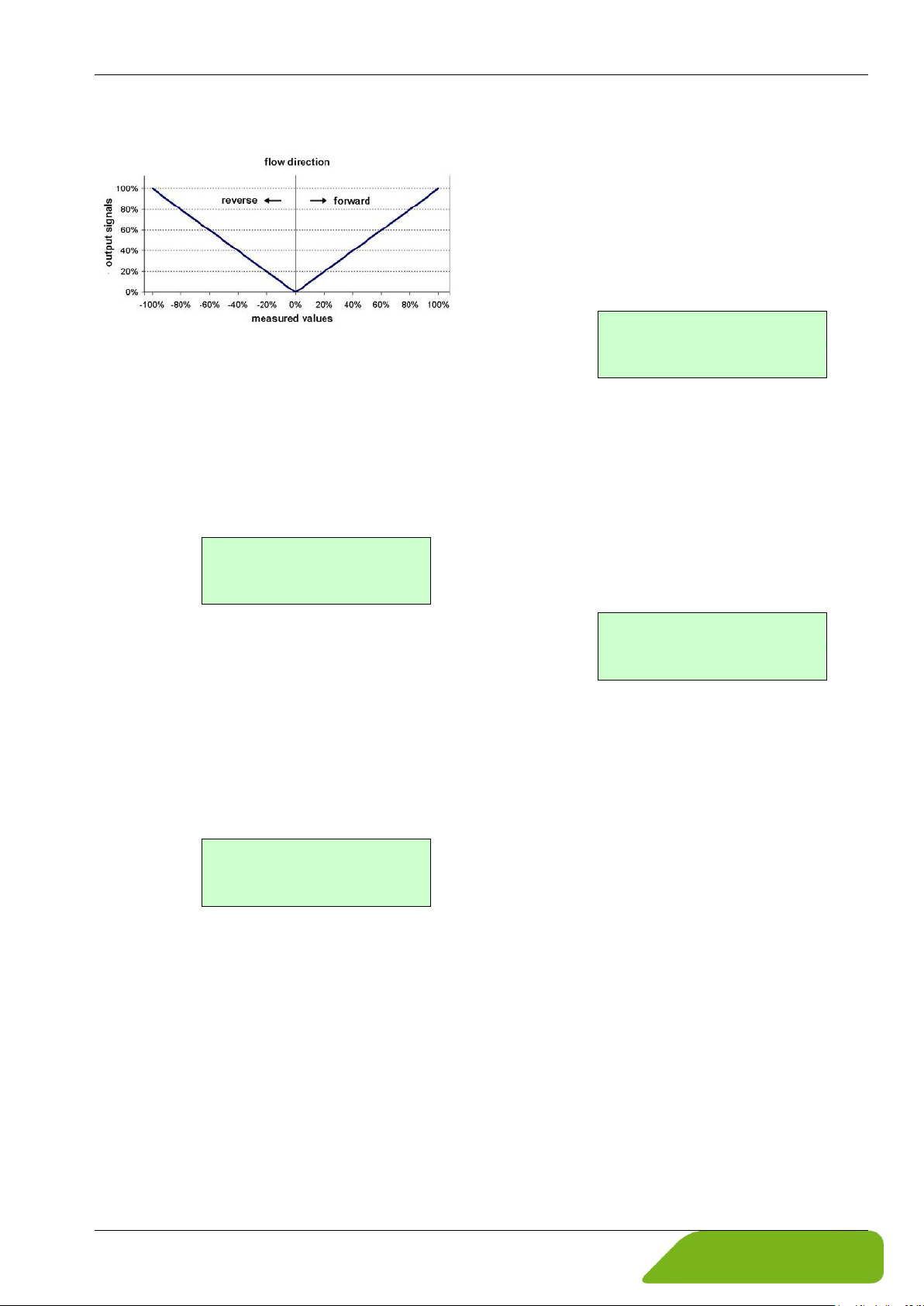
induQ
Version of VMM
01.70
Serial number
0100683
System errors
0000000
Reset error
[no]
®
- Series VMM Operation
forward & reverse:
Software version (information field):
After selecting the function Software ver-
sion
the version of the VMM software will be
displayed:
After choosing the desired function using the
key or and pressing Enter, the software
version will be displayed:
Example:
Show system errors:
This function is intended to show the history
of system errors that have occurred.
After selecting the function show system
errors
using key or and pressing Enter, the code of last system error will be displayed ( 8.1 "System errors").
Example:
Reset system error:
This function is intended to reset the system
error list.
After fixing the error cause the corresponding system error can be reset. Therefore select the function reset system error using key or and pressing Enter. The following message will be displayed:
Serial number (information field):
The parameter Serial number is unique
and allows a reference if the device needs
servicing. The serial number is printed on
the rating plate of the display electronics.
After selecting this function using the key
or and pressing Enter, the serial number
will be displayed.
Example:
To reset a system error, you need to toggle
to [yes] explicitly. By pressing Esc or toggling
to [no] the current action will be aborted, the
menu item is quitted without resetting
( "Selection window / make a selection",
p. 23).
If the message reappears shortly after, do
contact our technical service department.
Technical changes reserved - 45 -
Page 46
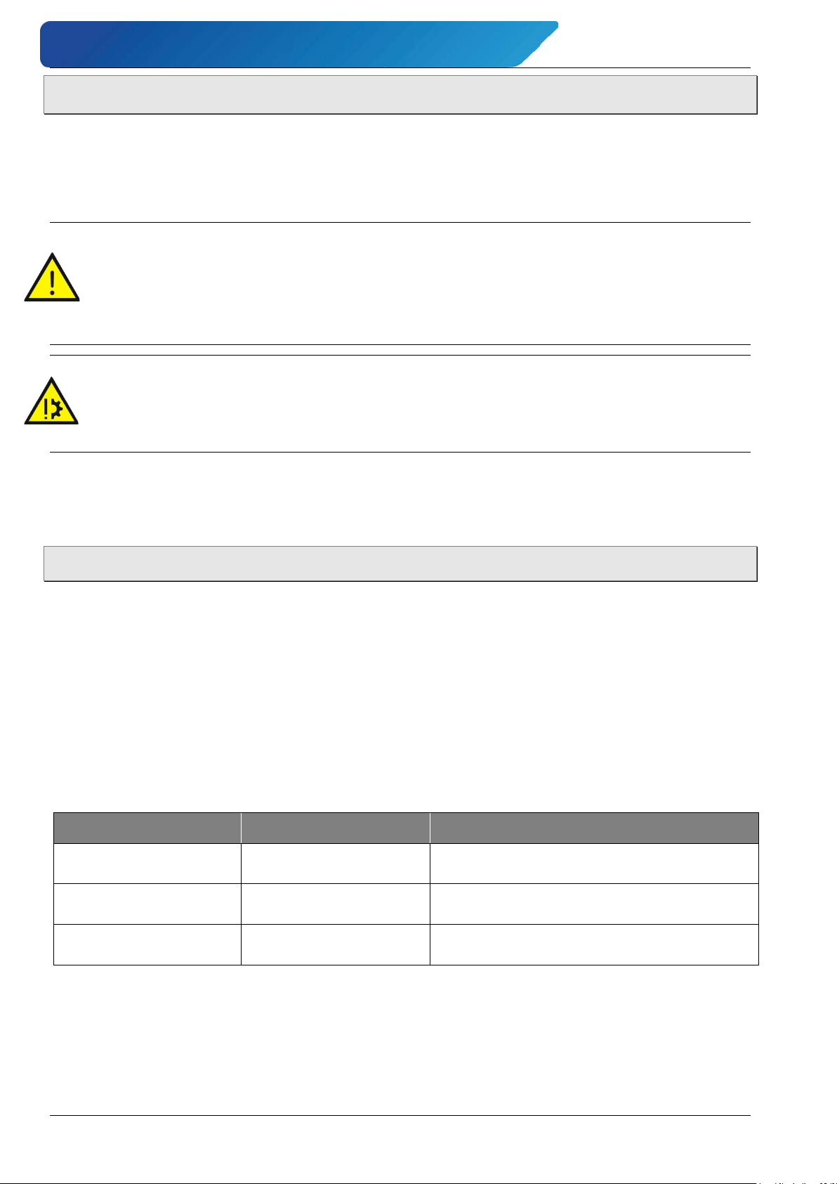
Errors and returns induQ
Identifier
Error code
Description
System errorExtEEProm
0x00002
External EEPROM (data memory chip DSM)
plugged in but is empty, not initialized.
System errorIntEEProm
0x00004
Internal EEPROM (calibration display electronics) present but empty / not described.
System errorEEPROM
0x00010
Failure when saving or reading of memory data.
®
- Series VMM
8 Errors and returns
Based on the meticulous manufacturing process, performance test and final inspection of the
device, trouble-free operation of the VMM is expected when installed and operated in accordance with this manual. However, if it nevertheless becomes necessary to return the unit to
SIKA, please follow the instructions in the following section.
WARNING! Risk of injury through toxic or hazardous substances!
Remnants of toxic or hazardous substances in the dismantled VMM can lead to damage
to health or cause significant property damage.
Purge or neutralize the unit before return shipment!
Comply with § 8.3 "Return shipment to the manufacturer"!
CAUTION! Material damage!
The VMM cannot be repaired by the user. In case of a defect, the device must be returned
to the manufacturer for repair.
Never perform any repair on the VMM yourself.
The integrated diagnostic system of the VMM distinguishes between two types of errors: System errors ( § 8.1) and Self-test errors ( § 8.2).
8.1 System errors
Errors that indicate system memory failure, division by zero or a damage of the electronics
unit are characterized as system errors. These error messages are not reset automatically
when the error disappears.
If the cause of any error messages described below cannot be fixed, please contact the SIKA
Service.
System errors will be displayed starting with the message “system error” followed by a 5digit number in hexadecimal code.
The error codes are explained in the following table.
If several errors occur at the same time, the hexadecimal sum of the individual errors will be
displayed. This allows an easy identification of the single error codes.
- 46 - © SIKA • Ba_VMM_us • 09/2018
Page 47
induQ
Problem
Empty pipe
Empty-pipe detection has been activated,
pipe is empty
Filling must be ensured
Exciter current
Interruption / short circuit in the excitation
coil. All signal outputs will be set to zero.
Check the wiring between field
coil and display electronics.
The measured electrode voltage is too high.
Vmax > 32.8 ft/s (10 m/s).
Current saturated
The current output is overloaded.
rent assigned measured variable, the output
Flow rate exceeds the upper
and the flow rate settings.
Pulse output saturated
The current measured value requires a
pulse rate, which can not be generated with
the set pulse duration and pulse value.
Check pulse duration, pulse val-
Check the flow rate.
Parameter inconsistent
The set parameters are contradictory.
value, pulse value and pulse duration has to
fit for all measured values.
Check the parameter settings.
Missing EEPROM
The data memory module (DSM) with the
tronics is missing.
Insert the data storage module
®
- Series VMM Errors and returns
8.2 Self-test errors
Self-test errors such as problems with a sensor line or inconsistent parameter settings are
displayed as textual error messages on the LCD. When the cause of error has been fixed, the
message disappears from the display automatically.
When a self-test error occurs the corresponding error message is displayed as plain text in
the second line of the LCD.
The language is set by parameter language ( Parameter "Language" in § 7.1.11) to English
(standard) or German.
The following table details what problems you can solve yourself and how to solve them.
(indication on the
display)
Measuring circuit saturated
Possible cause Troubleshooting
All signal outputs will be set to zero.
Based on the selected settings and the cur-
current is > 20.4 mA.
Example: The combination of Upper-range
Flow rate exceeds the upper
range value.
range value.
Vmax > 32.8 ft/s (10 m/s).
Check the upper-range value
ue, and measuring range.
calibration data of the sensor and the customer-specific settings of the display elec-
If it is not possible to rectify a problem, please return the unit for repair together with a short
error description, the ambient conditions and the period of use until the problem appeared.
Technical changes reserved - 47 -
(DSM) in the socket on the power supply board.
Page 48
Errors and returns induQ
®
- Series VMM
IMPORTANT! Error message: Parameter is inconsistent!
To recall a list of all inconsistencies, first enter a valid password and immediately an invalid password. The control unit will show a complete list of current errors (only once).
After entering the correct password, the inconsistent settings can be corrected.
8.3 Return shipment to the manufacturer
Due to legal requirements placed on environmental protection and occupational safety and
health and to maintain the health and safety of our employees, all units returned to SIKA for
repair must be free of toxins and hazardous substances. That also applies to cavities in the
devices. If necessary, the customer must neutralize or purge the unit before return to SIKA.
Costs incurred due to inadequate cleaning of the device and possible costs for disposal
and/or personal injuries will be billed to the operating company.
WARNING! Risk of injury due to insufficient cleaning!
The operating company is responsible for all damages and harm of any kind, in particular physical injuries (e.g. caustic burns or toxic contaminations), decontamination
measures, disposal etc. that can be attributed to insufficient cleaning of the measuring
instrument.
Comply with the instructions below before returning the unit.
The following measures must be taken before you send the unit to SIKA for repair:
Clean the device thoroughly. This is of extreme importance if the medium is hazardous to
health, i.e. caustic, toxic, carcinogenic or radioactive etc.
Remove all residues of the media and pay special attention to sealing grooves and slits.
Attach a note describing the malfunction, state the application field and the chemi-
cal/physical properties of the media.
Please follow the instructions on the procedure for sending returns which are on our
website (www.sika.net/en/services/return-of-products-rma.html) and please specify a
point of contact in case our service department has any questions.
The customer must confirm that the measures were taken by filling out the declaration of
decontamination. It can be found on our website as a download:
www.sika.net/images/RMA/Form_return_of_products.pdf
- 48 - © SIKA • Ba_VMM_us • 09/2018
Page 49
induQ
Mains fuse:
- Braking capacity 80 A @250 V AC
®
- Series VMM Cleaning, maintenance, storage
9 Cleaning, maintenance, storage
9.1 Cleaning
Clean the VMM with a dry or slightly damp lint-free cloth. Do not use sharp objects or aggressive agents for cleaning.
9.2 Maintenance
The VMM is maintenance-free cannot be repaired by the user. In case of a defect, the device
must be replaced or returned to the manufacturer for repair.
The VMM has no parts which have to be replaced or adjusted regularly.
Even though the units are maintenance-free, it is recommended to check the flow meter for
signs of corrosion, mechanical wear and damages at regular intervals.
We recommend routine checks at least once annually.
To clean and visually inspect the electrodes and the interior lining, the unit has to be re-
moved from the pipeline.
CAUTION! Risk of injury!
Perform all installation and connection work only when the supply voltage is switched
off.
The connection between sensor and display electronics under voltage must not disconnected or short-circuited!
Make sure that the plant is shut down professionally.
CAUTION! Risk of injury or material damage!
When removing the unit from the pipeline, take appropriate safety precautions. Always
use new gaskets during the new installation in the pipeline.
Mains fuse:
The mains fuse is located in the terminal compartment. Before replacing the fuse, the power
has to be switched off. Check carefully that the transmitter is voltage free.
The fuse may only be replaced by the exactly same type of fuse!
- 0.2 x 0.8 in(5 x 20 mm) (according to DIN 41571-3)
- Rated voltage 250 V AC
115/230 VAC = 100 mA (T)
24 V
= 1 mA (T)
DC
Technical changes reserved - 49 -
Page 50
Disassembly and disposal induQ
9.3 Storage
The device is to be safeguarded against dampness, dirt, impact and damage.
Store the VMM dry and dust free.
Prevent direct, permanent solar radiation and heat.
Prevent external loads on the unit.
The permissible storage temperatures are -4…140 °F.
10 Disassembly and disposal
CAUTION! Risk of injury!
Never remove the device from a plant in operation.
Make sure that the plant is shut down professionally.
®
- Series VMM
Before disassembly:
Prior to disassembly, ensure that
the equipment is switched off and is in a safe and de-energized state.
the equipment is depressurized and has cooled down.
Disassembly:
Remove the electrical connectors.
Remove the VMM using suitable tools.
Disposal:
Compliant with the Directives 2011/65/EU (RoHS) and 2012/19/EU (WEEE)*, the device must
be disposed of separately as electrical and electronic waste.
No household waste!
The VMM consists of various different materials. It should not be disposed of with household waste.
Comply with the relevant regulations of your country when disposing the units.
Take the VMM to your local recycling plant
or
send the VMM back to your supplier or to SIKA.
* WEEE reg. no.: DE 25976360
- 50 - © SIKA • Ba_VMM_us • 09/2018
Page 51
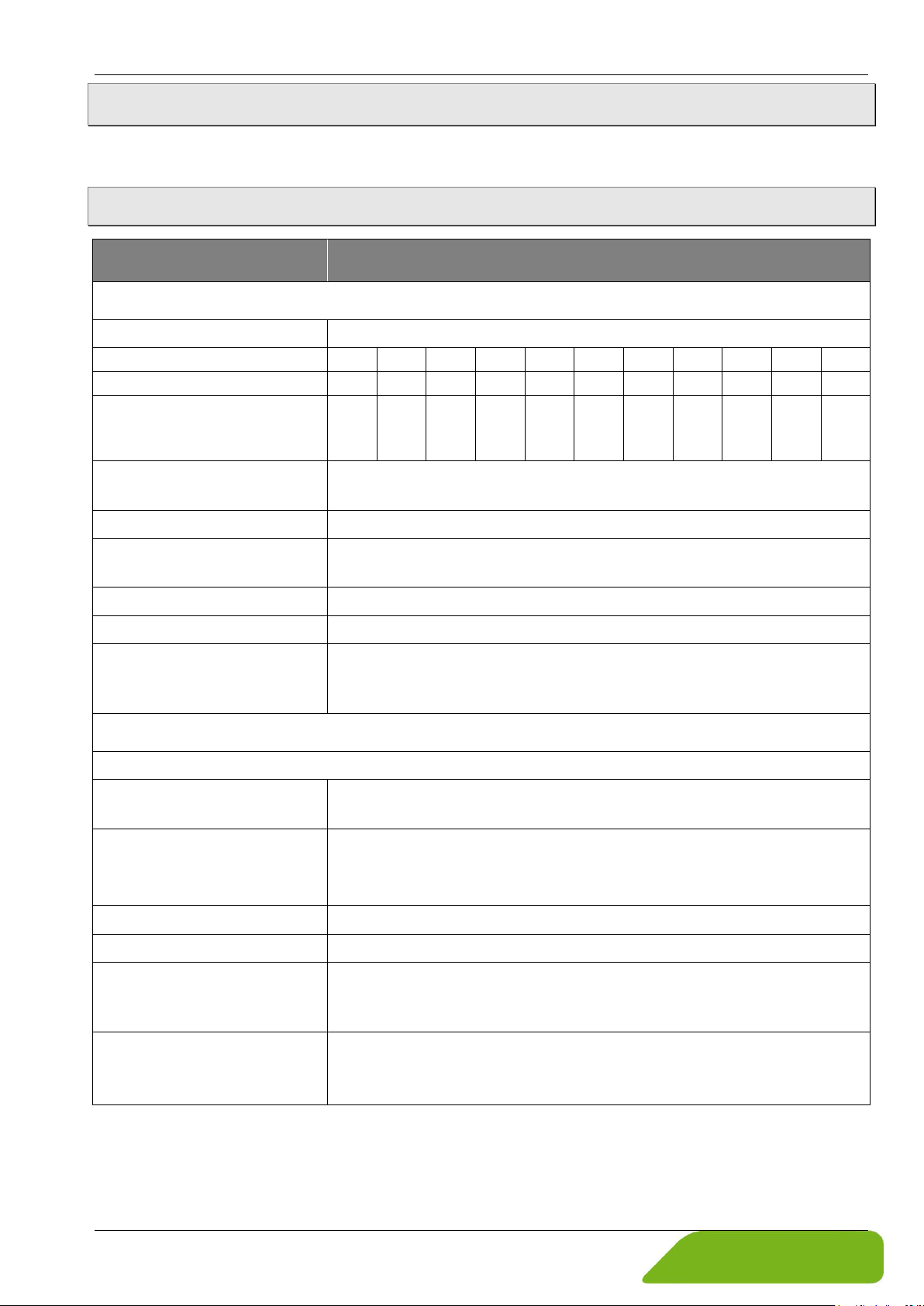
induQ
Measuring range
0…33 ft/s (0…10 m/s)
- Nominal pipe size
½"
1"
1 ¼"
1 ½"
2"
2 ½"
3"
4"
5"
6"
8"
- from 0 to [GPM]
27
77
127
199
310
525
796
1244
1944
2800
4979
- factory scaled measuring
from 0 to [GPM]
Accuracy *1)
±0.5 % of reading (3.28…32.8 ft/s)
±0.4 % of reading ±0.0033 ft/s (< 3.28 ft/s)
Repeatability
±0.15 % of reading (0.8…32.8 ft/s)
Output signal starting from
> 0 ft/s (depending on the electronics settings, for example on low-
flow suppression)
Response time
< 100 ms (depending on the electronics settings)
Measuring principle
Clocked DC field (DC)
Mounting position:
- outlet section
§ 4.3
2 x inner diameter (ID)
Electrical characteristics:
Measured value and measured range
Induced voltage of the connected sensor
Supply voltage
115 VAC • (-15/+10 %) • 50/60 Hz
Power consumption
15 VA
Electrical connection
Terminal strips
Cable glands
- Sockets
M16x1.5 • (metal)
*2)
- Line 2
LCD, backlight
®
- Series VMM Technical data
11 Technical data
The technical data of customized versions may differ from the data in these instructions.
Please observe the information specified on the type plate.
11.1 Characteristics of the VMM
Type VMM32 …VMM200
Characteristics Sensor
range (0/4…20 mA)
- inlet section
15 50 50 50 100 250 250 300 500 700 1000
Characteristics display electronics
5 x inner diameter (ID)
230 VAC • (-15/+10 %) • 50/60 Hz
18…36 VDC
- Display electronics
Display
- Line 1
*1)
Reference conditions: Media temperature 50...86 °F; Ambient temperature 68...86 °F; warm-up period 30 min.;
straight pipe lengths; inlet 5 x inner diameter, outlet 2 x inner diameter, regularly centered and grounded.
*2)
adjustable via menu.
Technical changes reserved - 51 -
M20x1.5 • (plastic)
flow rate in GPM
flow velocity in m/s
Page 52
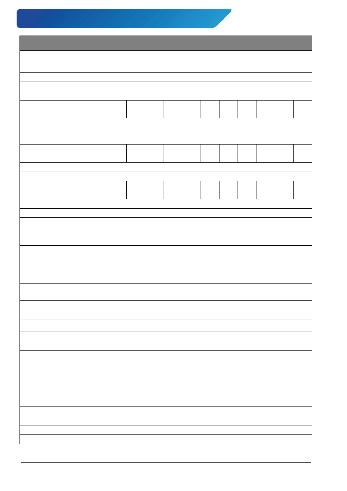
Technical data induQ
Pulse / Frequency output:
Signal type (selectable)
Pulse signal or frequency signal
Signal shape
Square wave signal
Pulse output:
Pulse rate: ID
½"
1"
1 ¼"
1 ½"
2"
2 ½"
3"
4"
5"
6"
8"
- factory-set [pulses/gal]
5 5 5 5 5 5 5 5 2 2 1
-
- Pulse width
≥ 0.1 ms (max. 2s) • adjustable
Frequency output:
0…1 kHz 1): ID
½"
1"
1 ¼"
1 ½"
2"
2 ½"
3"
4"
5"
6"
8"
- from 0 to [GPM]
15
50
50
50
100
250
250
300
500
700
1000
Accuracy
additionally ±0.05 % per 10 K
Analog output:
0/4…20 mA 1): ID
½"
1"
1 ¼"
1 ½"
2"
2 ½"
3"
4"
5"
6"
8"
- from 0 to [GPM]
15
50
50
50
100
250
250
300
500
700
1000
Signal current (selectable)
0…20 mA • 4…20 mA (active)
Current limitation
21.6 mA
Accuracy
additionally ±0.1 % per 10 K
Max. load
≤ 600 Ω
Short-circuit proof
Permanent
Status output / Frequency output:
as frequency output
max. 1 kHz
Version
Optocoupler
Switching values
UN 24 V • U
max
30 V • I
max
60 mA • P
max
1.8 W
Function status output (selectable)
forward flow • reverse flow • MIN flow rate • MAX flow rate •
alarm (adjustable)
Low-flow suppression
3% of the measuring range end value (adjustable: 0…20 %)
Damping
3 s • 0…60 s (programmable)
Medium to measure:
Water and other conductive liquids
- Conductivity
> 50 µS/cm
- Temperature
Hard rubber: 0…194 °F
Stainless steel: min. -4 °F
- Flow velocity
0.82…33 ft/s
- Viscosity
no restrictions
- Aggregate state
liquid
- Empty pipe detection
can be activated and deactivated
Type VMM32 …VMM200
Output signal display electronics
®
- Series VMM
Pulse significance
≤ 1000 Pulse/s
Process variables
PTFE (580 psi): -4…212 °F
PTFE (362 psi): -4…302 °F
PTFE (232 psi): -4…356 °F
Process connections
Steel: min. 14 °F
1)
factory scaled measuring range for … corresponds to:
- 52 - © SIKA • Ba_VMM_us • 09/2018
Page 53
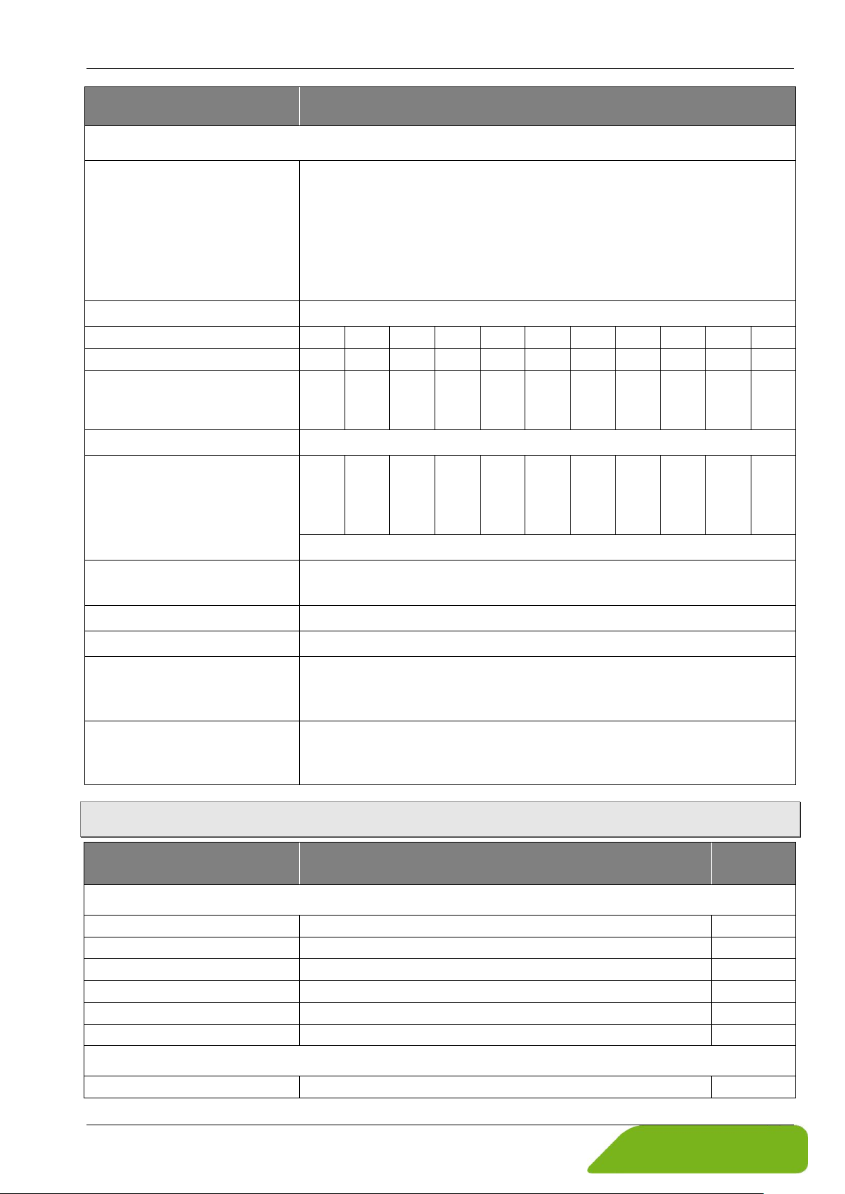
induQ
Ambient temperature
Hard rubber: 32...176 °F
Stainless steel: min. -4 °F
Transportation / storage temperature
-4…140 °F
Nominal pipe size
½"
1"
1 ¼"
1 ½"
2"
2 ½"
3"
4"
5"
6"
8"
Nominal Diameter DN …
15
25
32
40
50
65
80
100
125
150
200
Inner diameter
- PTFE [in]
0.55
1.06
1.31
1.50
1.91
2.49
2.99
4.04
4.91
6.00
7.92
Compressive strength
- EN 1092-1
PN 40
PN 40
PN 40
PN 40
PN 40
PN 16
PN16
PN 16
PN 40
PN 16
PN 40
PN 16
PN 10
PN 40
- JIS B2220 10K
142 psi
- ANSI B16.5 150RF
285 psi (Process connection, steel)
230 psi (Process connection, stainless steel)
Degree of protection (EN 60529)
IP 67
Corrosion protection class
C2 (slightly contaminated atmospheres, dry climate)
Dimensions and weights
- Display electronics
5.3 lb
Reference conditions
temperature: T = 68 °F (20 °C)
air pressure: p = 14.7 psi (101.3 kPa)
Component
Housing
Steel
Coils chamber
Steel
Measuring tube
Stainless steel
Measuring tube lining
PTFE or hard rubber
X
Electrodes
Stainless steel 1.4571 or Hastelloy C276
X
Process connections
Steel 1.0460 or Stainless steel 1.4404
Housing
Die-cast aluminum
®
- Series VMM Technical data
Type VMM32 …VMM200
Process variables
PTFE: -4…212 °F
Display electronics: -4…122 °F
(the readability of the LCD is restricted below 32 °F)
Process connections
Steel: min. 14 °F
- Hart rubber [in]
PN 16 at DN 65 for 8 bolt flanges
- Sensor
according to IEC 770
0.55
1.06
1.31
1.50
1.91
2.53
PN 40
3.03
PN 40
§ 11.3
relative humidity: rH = 65 %
4.04
5.03
6.15
PN 40
8.07
PN 16
PN 25
11.2 Materials table
Component Material
Components Sensor
Components display electronics
Technical changes reserved - 53 -
wetted
Page 54
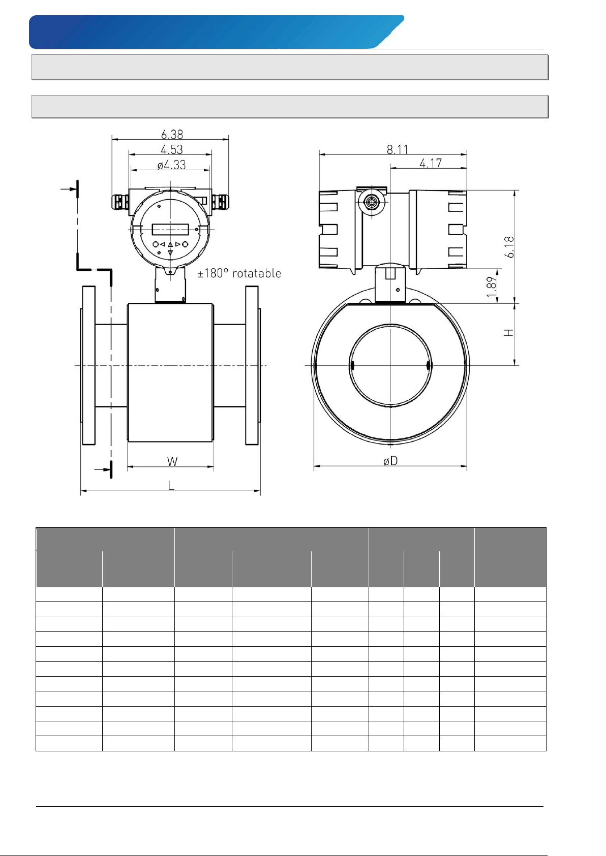
Technical data induQ
½"
DN 15
7.87
7.87 • 8.11
+0 / -0.12
3.15
5.12
2.09
9.8 • 16.4
1"
DN 25
7.87
7.87 • 8.11
+0 / -0.12
3.15
5.12
2.09
11.8 • 18.4
1 ¼"
DN 32
7.87
7.87 • 8.11
+0 / -0.12
3.15
5.12
2.09
11.9 • 18.6
1 ½"
DN 40
7.87
7.87 • 8.11
+0 / -0.12
3.15
5.12
2.09
13.2 • 19.8
2"
DN 50
7.87
7.87 • 8.11
+0 / -0.12
3.15
5.51
2.24
16.9 • 23.5
2 ½"
DN 65
7.87
7.87 • 8.11
+0 / -0.12
3.15
6.10
2.48
22.6 • 29.2
3"
DN 80
7.87
7.87 • 8.11
+0 / -0.12
3.15
6.69
2.76
29.8 • 36.4
4"
DN 100
9.84
9.84 • 10.08
+0 / -0.12
4.72
8.27
3.39
37.1 • 43.7
5"
DN 125
9.84
9.84 • 10.08
+0 / -0.12
4.72
9.45
3.86
44.8 • 51.4
6"
DN 150
11.81
11.81 • 12.05
+0 / -0.12
4.72
11.22
4.61
52.1 • 58.7
8"
DN 200
13.78
13.78 • 14.17
+0 / -0.12
7.87
13.78
5.63
91.8 • 98.5
11.3 Dimensions and weights
11.3.1 Compact device
®
- Series VMM
Dimensions [in]
Process connection
ANSI B16.5
150RF
1)
for process connection according to ANSI B16.5 150 RF. Weight: Sensor • Compact device.
2)
installation length: without protection ring • with protection ring.
EN 1092-1 /
JIS B2220 10K
rubber
Installation length L Sensor housing
Hard
PTFE 2)
Toler-
ance W D H [lb]
Weight 1)
- 54 - © SIKA • Ba_VMM_us • 09/2018
Page 55
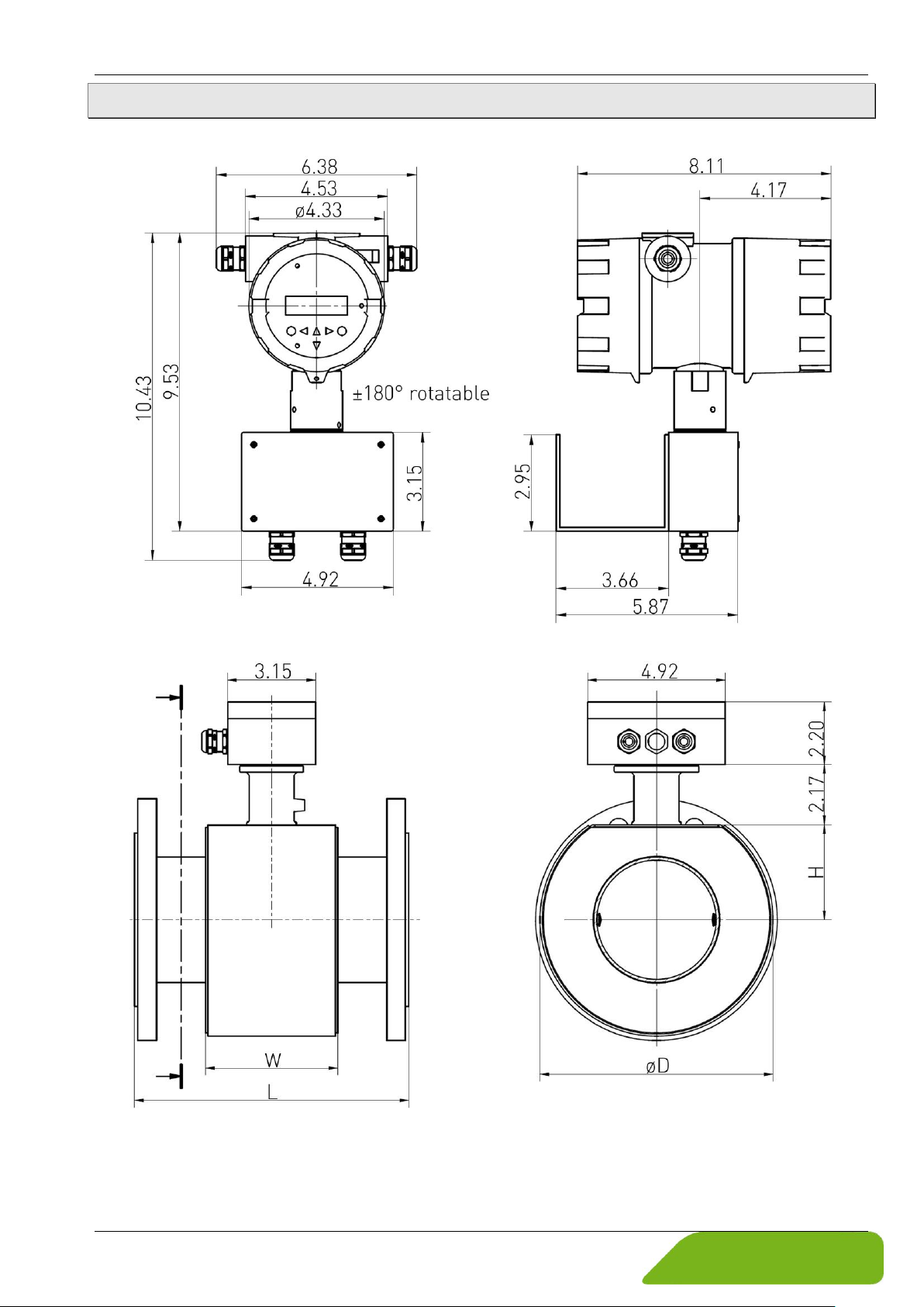
induQ
®
- Series VMM Technical data
11.3.2 Separate version (with wall bracket)
Display electronics:
Sensor:
The dimensions L, W, D and H correspond to the values of the table on the compact device ( § 11.3.1).
Technical changes reserved - 55 -
Page 56
induQ
®
- Series VMM
Sensors and Measuring Instruments
Flow Measuring Instruments
Test and Calibration Instruments
SIKA USA Inc.
1500 S. Sylvania Ave. Suite 111
Sturtevant WI 53177
262 886-2695
262 898-0101
info@sika-usa.com
www.sika-usa.com
- 56 - © SIKA • Ba_VMM_us • 09/2018
 Loading...