

Page 1

USER’S GUIDE
Thermal Printer
DPU-3445-20
Read this user’s guide carefully before
using the printer.
Keep this user’s guide in a place where it
can be accessed quickly.
Seiko Instruments Inc.
Page 2
DPU-3445-20 THERMAL PRINTER USER’S GUIDE
Document Number U00018388105
First Edition May 1999
Second Edition January 2000
Third Edition April 2000
Fourth Edition December 2000
Fifth Edition May 2001
Sixth Edition November 2001
Copyright 1999, 2000, 2001 by Seiko Instrum ents Inc.
All rights reserved.
Seiko Instruments Inc. (SII) has prepared this User’s Guide for use by SII
personnel, licensees, and customers. The information contained herein is the
property of SII and shall not be reproduced in whole or in part without the prior
written approval of SII.
SII reserves the right to make changes without notice to the specifications and
materials contained herein and shall not be responsible for any damages
(including consequential) caused by reliance on the mat erials present ed, including
but not limited to typographical, arithmetic, or listing errors.
BHT Ir is a trademark of DENSO INDUSTRIES I NC.
is a trademark of Seiko Instruments Inc.
All other trademarks are t he pr operties of their respective companies.
Applicable EC Directives and Standards
Product: Thermal Printer DPU-3445-10A,DPU-3445-20A, AC Adapter PW-3009-W2
Directives Title
89/336/EEC EC Electromagnetic Compatibility Directive
Standards
EMI: EN50081-1/1997
EN55022/1994+Amd.1/1995 class B, EN61000-3-2/1995, EN61000-3-3/1995
EMS: EN55024/1998
IEC61000-4-2/1995, IEC61000-4-3/1995, IEC61000-4-4/1995,
IEC61000-4-5/1995, IEC61000-4-6/1996, IEC61000-4-8/1993,
IEC61000-4-11/1994
Product : AC Adapter PW-3009-W2
Directives Title
73/23/EEC EC Low Voltage Directive
Standards
LVD: EN60950/1992 +Amd.1+Amd.2 +Amd.3
IEC950/1991+Amd.1/1992+Amd.2/1993+Amd.3/1995+Amd.4/1996
Product: Battery Charger BC-3008-W1
Directives Title
89/336/EEC EC Electromagnetic Compatibility Directive
73/23/EEC EC Low Voltage Directive
Standards
EMI: EN50081-1, EN55022/1995 class B, EN61000-3-2/1995, EN61000-3-3/1995
EMS: EN55024/1998
LVD: EN60950 +Amd.1 +Amd.2, IEC950/1991 +Amd.1/1992 +Amd.2/1993
Page 3
This equipment has been tested and found to comply with the limits for a Class B
digital device pursuant to Part 15 of t he FCC Rules. These limit s are desig ned to
provide reasonable protection against harmful interference in a residential
installation. This equipment generates, uses and can radiate radio frequency
energy and, if not installed and used in accordance with the instructions, may
cause harmful interference to radio communications. However, there is no
guarantee that interference will not occur in a particular installation.
It can be determined whether this equipment is causing int erference by turning it
off. If the interference stops, it was probably caused by the equipment.
If the equipment does cause interfer ence, try to correct t he interfer ence by one or
more of the following measures:
- Reorient or relocate the radio or television antenna.
- Increase the separation between the equipment and the radio or television.
- Connect the equipment to an outlet on a different circuit from the radio or
television.
- Consult the dealer or an experienced radio/TV technician for help.
Any changes to this certified device will void your legal right t o oper ate it.
All interface cables to and fr om t his device must be shielded with Ferr it e cor e.
Page 4

INTRODUCTION
User’s Guide applies to the DPU-3445-20 Thermal Printer.
Read through the Safety Precautions on pages 2 to 6 carefully before using the
printer. Also read the instruction manuals of the optional equipment that you
purchased with the printer.
The User’s Guide consists of the following sections.
SAFETY PRECAUTIONS............................................................................ 2
OPERATING PRECAUTIONS .................................................................... 5
1 PREPARATION ................................................................................. 7
2 NAMES OF PARTS ........................................................................... 8
3 POWER CONNECTION .................................................................. 10
4 PAPER SETTING ............................................................................ 12
5 TEST PRINTING.............................................................................. 15
6 FUNCTION SETTING ...................................................................... 16
7 CONNECTING TO THE HOST COMPUTER................................... 22
8 RECHARGING THE BATTERY PACK............................................. 24
9 THERMAL HEAD MAINTENANCE .................................................. 26
10 TROUBLESCHOOTING .................................................................. 27
11 SPECIFICATIONS ........................................................................... 28
12 OPTIONS AND CONSUMABLE PARTS.......................................... 29
For more detailed technical information on this printer, please ask your dealer for a
copy of the DPU-3445-20 Technical Reference.
- 1 -
Page 5
SAFETY PRECAUTIONS
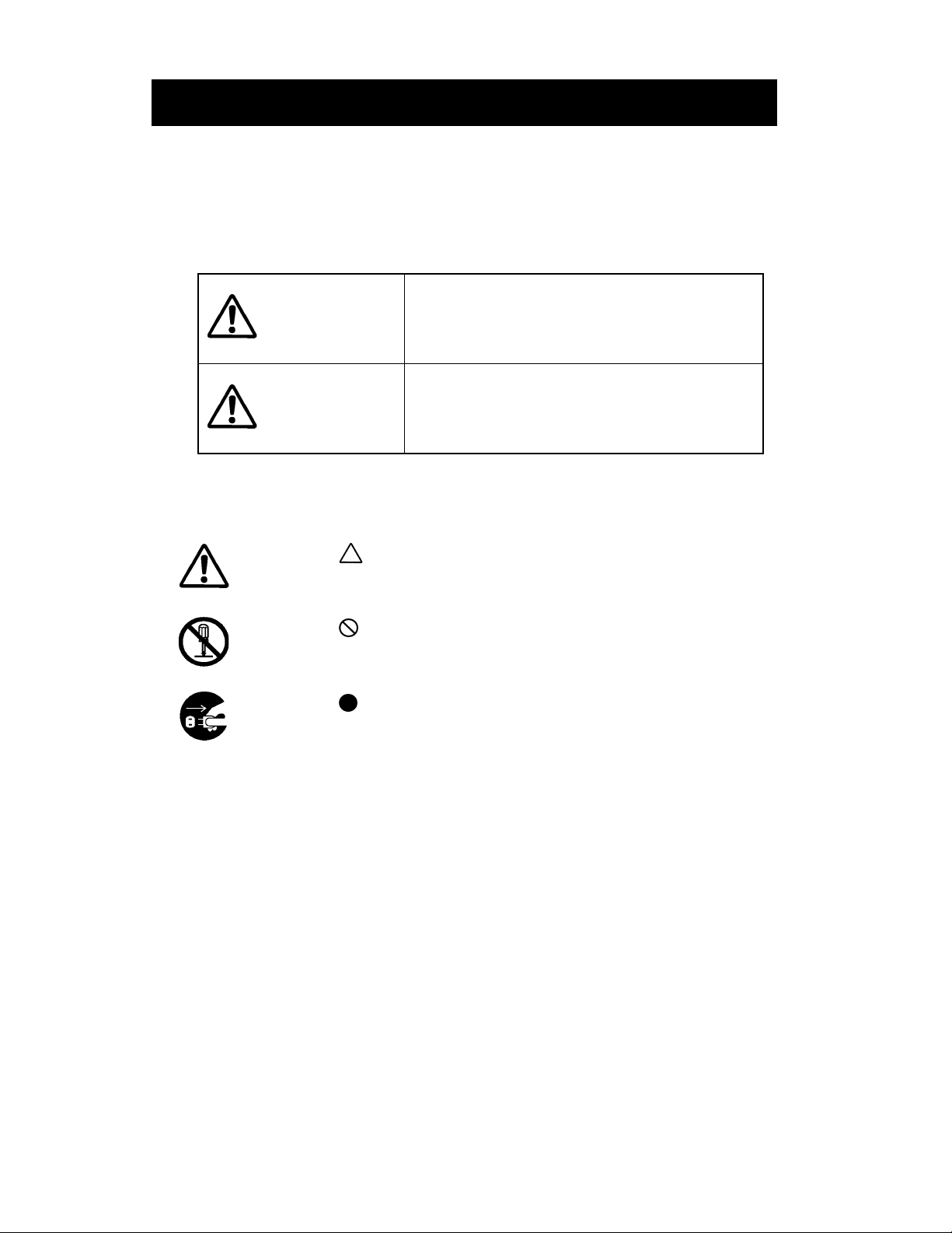
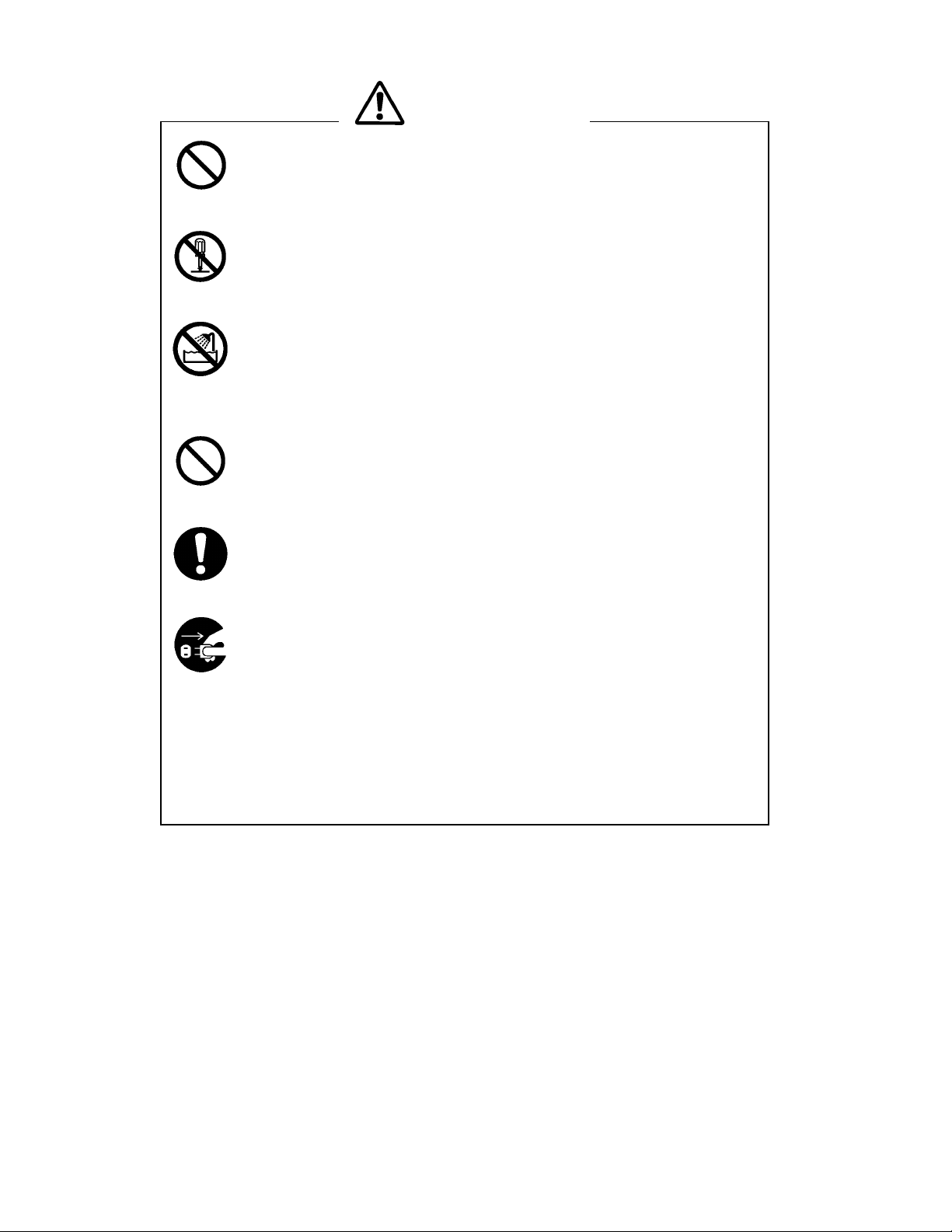
The following symbols are used in this User’s Guide in order to make use of the
printer properly and prevent the printer from being damaged.
Follow the instructions marked with the symbol.
Failure to follow the guidelines marked with
WARNING
CAUTION
Symbol Examples
The symbol indicates caution (including danger and warning).
The example on the left indicates warning or caution.
The symbol indicates prohibition.
The example on the left means prohibition of disassembling.
The symbol indicates requirement or what must be done.
The example on the left means “pull the power plug out of the outlet.”
this symbol could result in severe personal
injury or death.
Failure to follow the guidelines marked with
this symbol could result in minor personal
injury or product and/or peripheral damage.
- 2 -
Page 6
WARNING
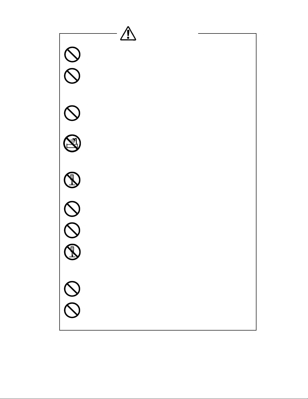
DO NOT use an AC adapter or battery pack other than that which is
specified. Doing so may cause fire leading to serious accidents.
DO NOT bend the power cable forcibly, or place heavy object on the
cable because it might damage the cable and cause fire or electric
shock. If the power cable is damaged, discontinue use and replace it
immediately.
DO NOT throw the battery pack into a fire or apply heat because it may
cause the battery pack to explode causing physical injury or property
damage.
DO NOT put the battery pack into water or use in a place where it could
get wet because it may cause fire or electric shock.
Failure to do so may cause leakage, explosions, or a fire in the battery
pack, which may lead to fires or personal injury.
DO NOT disassemble the battery pack because it may cause the
battery pack to heat up and catch fire, leading to other serious
accidents.
DO NOT short the battery pack terminals as it may lead to fire, electric
shock, or personal injury.
DO NOT subject the battery pack to direct sunlight or high temperature
as it may lead to fire or personal injury.
Never disassemble the AC adapter and battery charger. Failure to
follow this instruction may cause overheating or burning of the AC
adapter or the charger, or an electric shock, which may lead to fires or
accidents.
DO NOT remove the battery pack during recharging. You may get an
electric shock if you touch the terminal while in recharging mode.
Use the buttery charger recommended by SII to recharge the battery
pack. Use of other chargers may cause overheating or burning of the
battery pack, which may lead to fires or accidents.
- 3 -
Page 7
CAUTION
This printer is not designed to be dust-proof or water-proof. DO NOT
drop any metallic objects or liquids, such as water or coffee, into the
printer.
DO NOT disassemble or remodel the printer. DO NOT REPAIR THE
PRINTER YOURSELF. Doing so may cause fire, electric shock or
other accidents.
Never use the printer in a place of extreme humidity or any place
where it can possibly be splashed by any liquids. If any liquids get into
the printer, it could lead to fire, electric shock, or other serious
accidents.
Never touch the thermal head immediately after printing because it
becomes very hot. Make sure that the thermal head is cool before
clearing a paper jam or cleaning the thermal head.
Be sure to hold the connector part of the power cable or interface cable
when disconnecting the cable. Pulling on the cable portion may cause
it to fray and break.
Power OFF the printer, unplug the power cable from the power outlet,
and remove the battery pack in any of the following cases:
◆ The printer does not recover from an error.
◆ Smoke, strange noise or smells erupt from the printer.
◆ A piece of metal or any liquid touches the internal parts or slot of
the printer.
Using the printer in any manner other than for which it was designed
may cause accidents or fire.
- 4 -
Page 8

OPERATING PRECAUTIONS
Please follow the precautions below to enjoy and maintain the full performance of the
printer.
QQQQ Using the Printer
X Be careful not to drop or bump the printer on a hard surface.
X DO NOT install the printer in direct sunlight or such areas. Suitable environment
for the use of the printer is as follows:
· Ambient temperature: 41°F to 104°F (5°C to 40°C)
· Relative humidity: 30 to 80% (noncondensing)
X DO NOT install the printer near devices that generate strong electromagnetic
fields such as a copy machine.
X DO NOT connect the AC cables of the AC adapter and the battery charger to the
same outlet with devices that generate noise.
X DO NOT open the platen cover during printing.
X DO NOT remove or reinstall the interface cable during printing or transmission.
DO NOT touch the connectors of the interface cable during printing.
X DO NOT cut any sheets of thick paper or label paper with the paper cutter
installed in the paper outlet. Failure to follow this instruction may cause a cutting
error or make the cutting edge dull due to label paper adhesive sticking to the
cutter.
X Switch the power off when not in use.
X Clean the printer using soft, lint-free cloth. Do not use alcohol or other solvent.
X Before use, always clean the terminals using a dry, soft, lint-free cloth. If the
terminals are dirty, it may not be possible to obtain proper contact.
X The AC adapter, the battery charger and the battery pack may become warm
when in use. This is normal and is not a malfunction.
X When the battery pack is used at low temperature, the length of time the printer
can be used may be shortened.
X When printing with high print rate is performed on thick papers, uneven printing
may occur and the sound during printing may become louder. However, since this
symptom is caused by the type of paper used, it is not printer trouble.
- 5 -
Page 9

QQQQ Thermal Paper Handling
X Store the thermal paper in a cool, dry, and dark place.
X Do not rub the paper with hard objects.
X Do not leave the paper near organic solvents.
X Do not allow plastic film, erasers, or adhesive tape to touch the paper for long
periods.
X Do not stack the thermal paper with diazo copies immediately after copying or wet-
type copies.
X Do not use chemical glue.
X Always use the specified thermal paper. See Section 12, Options and
Consumable Parts, for details.
QQQQ Notations Used in this User’s Guide
The following two types of notations are used throughout this User’s Guide to denote
items of caution and items to remember:
NOTE
X Operation Precautions
This box contains items that when not followed may lead to a malfunction or to a
deterioration of performance.
HINT
•
Items To Remember
This box contains helpful hints to remember when using the printer.
- 6 -
Page 10
1 PREPARATION
A
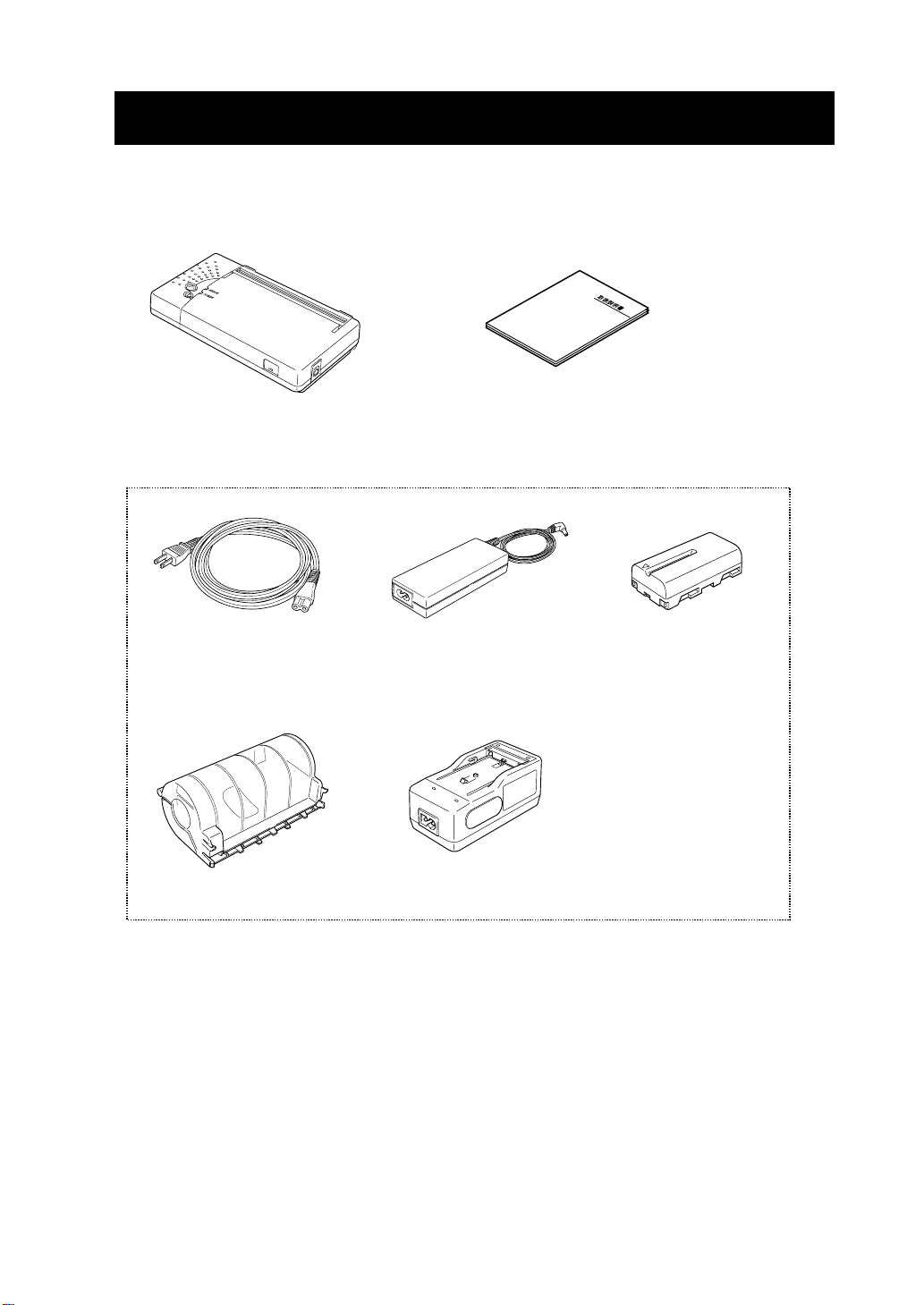
Once you have opened the carton, make sure it contains the printer and all
accessories.
Printer
The following are available as options:
C cable
Paper holder
AC adapter
Battery charger
Printer User’s Guide (this document)
Battery pack
Keep the package and packing materials for future transportation or long-term
storage.
The AC adapter and the battery charger is not bundled with an AC cable. An AC
cable should be ordered separately.
- 7 -
Page 11
2 NAMES OF PARTS
(3)
(4)
(2)
(1)
(7)
(8)
(9)
ER
W
PO
R
RO
ER
Front
(6)
(5)
Bottom
(14)
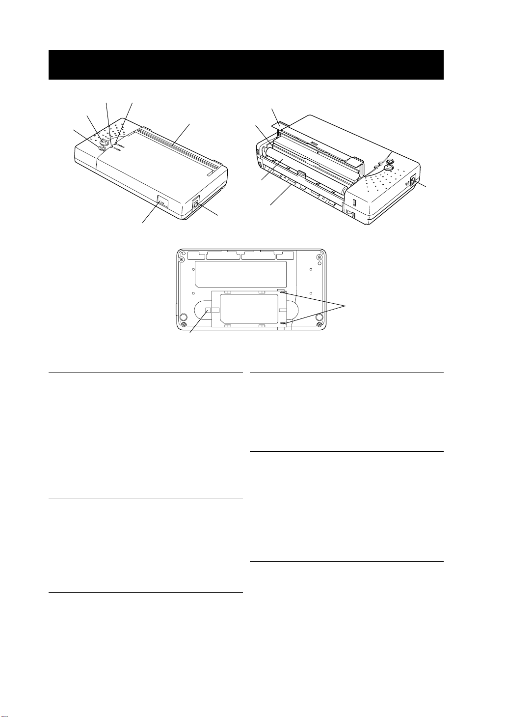
(1) POWER button
The POWER button turns the printer ON
or OFF. To turn the printer on, hold down
the POWER button until the POWER
lamp lights. To turn the printer off, hold
down the POWER button until the
POWER lamp goes off.
(2) FEED button
When this button is pressed once, a
small amount of paper is fed. When the
button is held down, the paper is fed
continuously.
(10)
(12)
Back
(11)
(13)
(4) ERROR lamp
The ERROR lamp lights when something
is wrong with the printer. See the Lamp
Display on the next page for details.
(5) Infrared transmitter/receiver
The infrared transmitter/receiver is used
to communicate with the host device
having the physical layer of IrDA which is
in accordance with the standards of the
physical layer of IrDA (Ver1.0) by IrDA.
(6) Interface connector
(3) POWER lamp
The POWER lamp lights when the printer
turns on. See the Lamp Display on the
next page for details.
Connects with the interface cable. Open
the rubber cover and insert the
connector.
- 8 -
Page 12
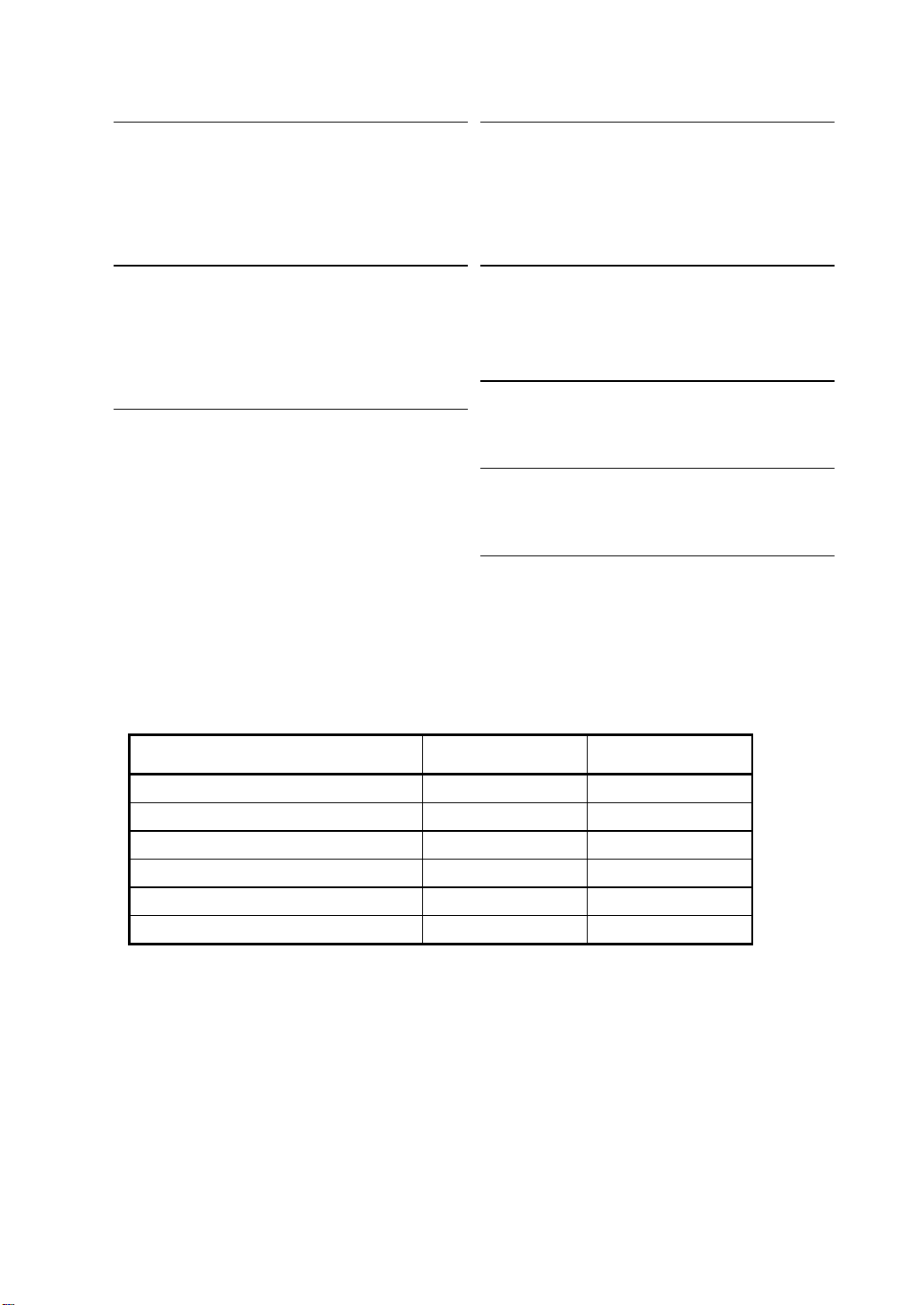
(7) Paper outlet
(10) Platen roller
Paper port with a paper cutter. When the
platen cover is closed, paper is
discharged from the top of the printer.
(8) Thermal head
The thermal head prints characters on
the paper. It is very hot immediately after
printing.
(9) Platen cover
When the platen cover is opened, the
thermal head moves away from the
paper. Open this cover to remove paper
or perform head cleaning.
The platen roller brings the paper in
contact with the thermal head. The
platen roller is turned to feed the paper.
(11) Power connector
Connects the AC adapter to this
connector.
(12) Paper slot
Paper inlet
(13) Battery connection terminal
Battery connection terminal
(14) Battery release button
Releases the battery pack from the
printer.
Lamp Display
Lamp display
POWER lamp
Power OFF Off Off
Power ON (standby mode) On Off
Paper-out, platen cover open On On
Battery low, power failure Blink On
Recharging Blink Off
Function setting mode Off On
ERROR lamp
- 9 -
Page 13
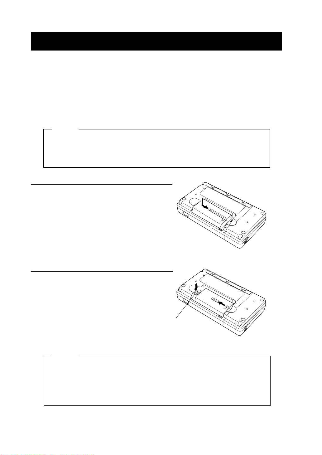
3 POWER CONNECTION
The printer can be powered with a battery pack or an AC adapter.
QQQQ Installing a Battery Pack
The battery pack should be fully recharged. See Section 8, Recharging the
Battery Pack, for details on the recharging method.
NOTE
Before installing or removing the battery pack, turn the printer off.
If the printer is not used for a long time, remove the battery pack from
the printer.
Installing the battery pack
Remove the terminal cover from the battery
pack.
Insert the battery pack in the direction of the
arrow so that the printer connection terminal
touches the connection terminal of the battery
pack.
Removing the battery pack
Turn the printer off.
Hold down the battery release button and slide
the battery pack in the direction of the arrow.
Release button
HINT
• Read the instruction manual supplied with the battery pack to use it
correctly.
• If the battery pack starts to run out soon, it means that the battery life
has expired. Purchase a new battery pack.
- 10 -
Page 14
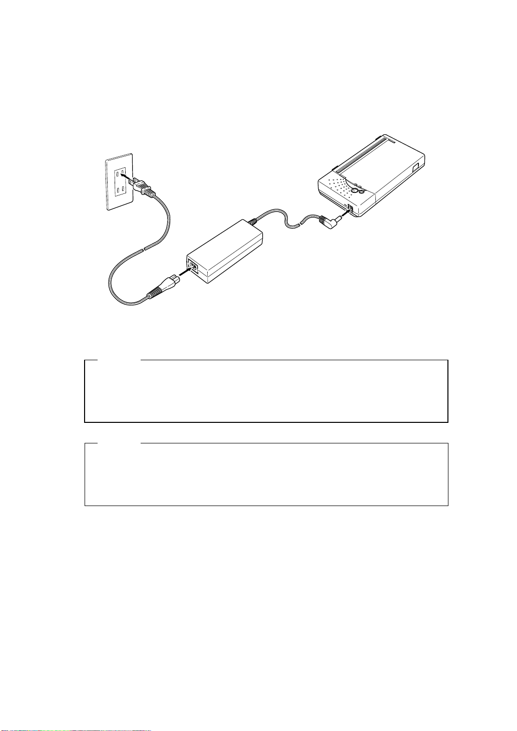
QQQQ Connecting the AC Adapter
(1) Connect the AC cable to the AC adapter.
(2) Insert the DC jack of the AC adapter to the power connector of the printer.
(3) Insert the AC plug of the AC cable to an electric outlet.
(3)
(2)
(1)
NOTE
Before installing or removing the AC adapter, turn the printer off.
If the printer is not used for a long time, unplug the AC cable from the
outlet.
HINT
• If the auto power off function is enabled, the printer turns off
automatically when it is not operated for 30 minutes to save the
battery. See Section 6, Function Setting, for details on settings.
- 11 -
Page 15
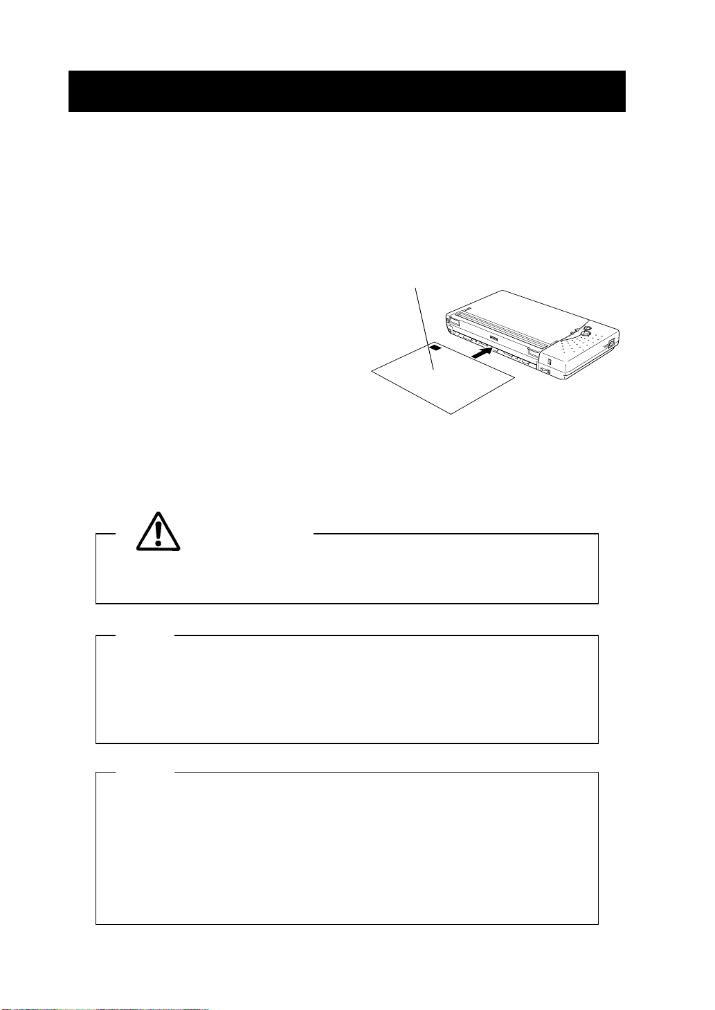
4 PAPER SETTING
This printer can feed cut sheets and roll paper. The printer function setting for cut
sheets is different from that for roll paper. See Section 6, Function Setting, for
details.
QQQQ Setting Cut Sheets
(1) Turn the printer on. The POWER and
ERROR lamps will light.
Place a cut sheet with the paper
position detection mark facing up.
(2) If the printer has been stored without
setting paper, open and close the platen
cover (see Section 2, Names of Parts)
before setting the cut sheet.
(3) Insert a cut sheet into the paper slot in
the printer until it stops with its printable
surface facing down.
(4) The printer detects the paper and loads it automatically.
(5) To discharge the paper from the printer, hold down the FEED button.
CAUTION
Take care not to get your fingers caught in the printer when loading
paper.
NOTE
Insert the paper into the slot straight. If it is askew, a paper feed error
occurs.
DO NOT block the paper outlet or hold the paper that is being loaded.
Otherwise, it may cause a paper jam.
R
E
W
O
P
R
O
R
R
E
HINT
• Marks for paper position detection are printed on the back of the
specified paper. When the printer detects the mark, it enters “standby
mode”.
• If the printer does not detect a mark, the ERROR lamp lights. Press
the FEED button once or turn the printer off and on again to clear the
error.
- 12 -
Page 16
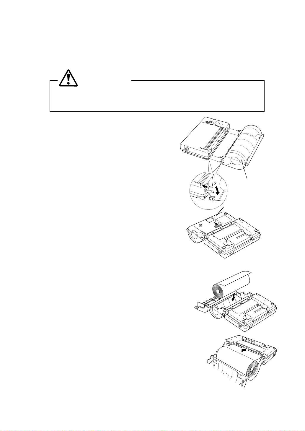
QQQQ Setting Roll Paper
This printer can be equipped with an optional paper holder to feed roll paper. Install
the paper holder, then set the paper.
CAUTION
Take care not to get your fingers caught in the printer when loading
paper.
(1) Insert the paper holder hooks into the upper
square holes on both sides of the platen
cover (shown 1 in figure). Push the paper
holder so that the paper holder tab is fit into
the lower square holes in the printer (shown 2
in figure). It clicks when the paper holder is
installed correctly.
(2) Turn the printer on.
Paper holder
(3) If the printer has been stored without setting
roll paper, open and close the platen cover (See
Section 2, Names of Parts) before setting the
roll paper.
(4) Turn the printer over, push the center of the
paper cover and slide it in the direction of the arrow.
The paper cover is unlocked and can be opened.
(5) Set the roll paper in the paper holder as shown in
the figure at the right. Insert the paper into the
paper slot of the printer until it stops.
When the printer detects the paper, it loads it
automatically. Close the paper cover and slide it in
the opposite direction of (3) until it clicks.
The paper cover is locked. To keep the paper
from falling out, fasten the paper cover
securely.
Paper cover
- 13 -
Page 17
(6) Turn the printer over again. The ERROR lamp should be lit. Press the FEED
button once, and the printer will go into standby mode.
HINT
• To remove the paper, turn the printer off and open the platen cover.
Turn the printer over, and open the paper cover. The paper can be
removed by pulling it upward.
NOTE
Insert the paper into the slot straight. If it is askew, a paper feed error
occurs.
DO NOT block the paper outlet or hold the paper that is being loaded.
Otherwise, it may cause a paper jam.
DO NOT force the paper holder, especially when the paper cover is
open.
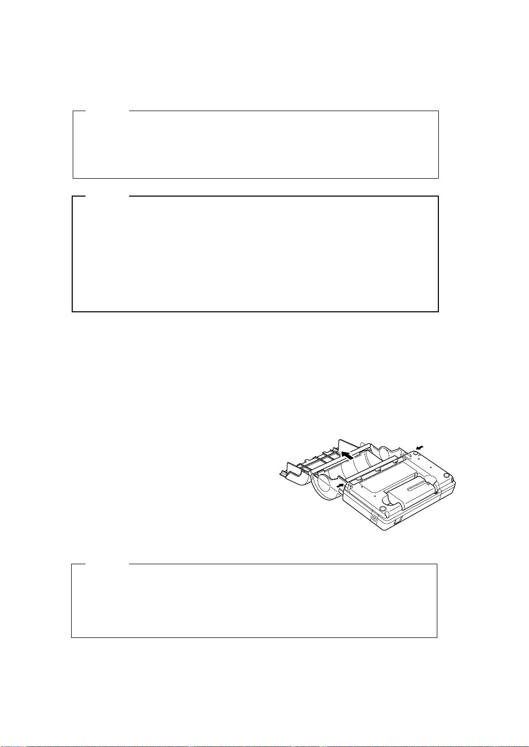
QQQQ Removing the Paper Holder
Cut sheets cannot be used with the paper holder installed. To use cut sheets,
remove the paper holder.
(1) Remove the roll paper from the paper holder.
(2) Open the paper cover, and push the right
and left tabs of the paper holder at the
same time to unlock them. The paper
holder can now be removed from the
printer.
HINT
• The printer function setting for cut sheets is different from that for roll
paper. When the paper type is changed, the function setting must be
modified accordingly. See Section 6, Function Setting, for details.
- 14 -
Page 18

5 TEST PRINTING
After loading paper in the printer, perform test printing. In test printing, the printer's
function setting and character strings for testing are printed.
(1) Make sure that the paper is loaded in the printer and the printer is off. If the paper
is not loaded, load the paper as instructed in Section 4, Paper Setting, and turn the
printer off.
(2) Press the POWER and FEED buttons at the same time. When the POWER lamp
lights, release the POWER button, then the FEED button.
(3) Several dozens of lines of text are printed.
"DPU-3445 "
"[Ver.*.**] **.***.****"
"Copyright (C) : SII"
"**************************"
.
.
.
(4) After test printing, the printer goes into standby mode.
- 15 -
Page 19

6 FUNCTION SETTING
This printer allows you to set various function according to operating conditions or
uses.
The settings are stored in the software DIP switches (non-volatile memory) in the
printer. They can be set by using buttons or by entering commands.
This manual describes how to set functions by using buttons.
HINT
• See the Technical Reference for details on function setting with
commands.
QQQQ Function Setting Mode
The printer must be in the function setting mode to set functions with buttons.
To enter the function setting mode, do as follows:
(1) Make sure that the paper is loaded in the printer and the printer is off. If the paper
is not loaded, load the paper as described in Section 4, Paper Setting, and then
turn the printer off.
HINT
• If an error occurs in the function setting mode, the POWER and
ERROR lamps blink 3 to 4 times and the power is turned off.
(2) Press the POWER and FEED buttons at the same time. When the POWER lamp
lights, and five seconds later the POWER and ERROR buttons start blinking,
release both of the buttons.
(3) If the message shown at the right is printed, press the FEED button.
Select Function
Setting Mode: Feed SW / HEX Dump Mode: Power SW
HINT
• If you press the POWER button, the printer enters the HEX Dump
mode. This mode enables you to see the printer's transmission status.
See the Technical Reference for details.
• If you do not press any button within 30 seconds after a message is
printed, the printer turns off.
- 16 -
Page 20

(4) If the message shown at the right is printed, press the FEED button.
[SETTING MODE] Yes: Feed SW / No: Power SW
HINT
• If you press the POWER button, the printer leaves the function setting
mode and turns off.
• If you do not press any button within 30 seconds after a message is
printed, the printer turns off.
The printer is now in the function setting mode. You can set functions by pressing
buttons.
QQQQ Changing Settings
In the function setting mode, you can initialize or modify settings. To set the settings
to defaults, perform operation (1). To change settings, perform operation (2).
(1) Initializing software DIP switch settings
1. When the message shown at the right is printed in the function setting mode,
press the FEED button.
Load Default Setting? Yes: Feed SW / No: Power SW
2. When the message shown at the right is printed, the printer turns off. The
settings are set to defaults. Initialization is complete.
Default Setting Saved.
Setting Mode Finished.
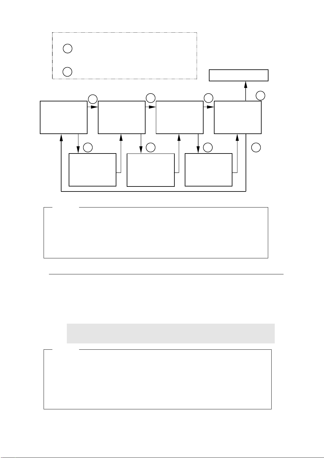
(2) Changing software DIP switch settings
When the message shown at the right is printed in the function setting mode,
press the POWER button.
Set the DIP switches as follows:
Load Default Setting? Yes: Feed SW / No: Power SW
- 17 -
Page 21
POWER
Press the POWER button.
L
FEED
Press the FEED button.
L
Setting complete
POWER
DIP switch 1
selection
Operation 1
FEED
DIP switch 2
selection
Operation 1
DIP switch 1
setting
Operation 2
HINT
• Each of DIP switches 1 to 3 has eight bits of data to be set.
• When the POWER or FEED button is pressed in the function setting
mode, the POWER lamp blinks once. Verify that the POWER lamp
blinks.
POWER POWER
DIP switch 3
selection
Operation 1
FEED FEED
DIP switch 2
setting
Operation 2
DIP switch 3
setting
Operation 2
Setting end
selection
Operation 3
POWER
FEED
Operation 1: DIP switch selection
If you press the FEED button when the message shown at the right is
printed, you can perform operation (2).
If you press the POWER button instead of the FEED button, the details of
the printed DIP switch (DIP switch 1) are not changed, and the next DIP
switch is selected (operation 1).
DIP Switch setting mode.
DIP SW-1=******** Change Setting? Yes: Feed SW / No: Power SW”
HINT
• "********" in the message indicates the setting of the DIP switch. The
leftmost bit is the most significant bit (bit 8) and the rightmost bit is the
least significant bit (bit 1).
• If all DIP switches 1 to 3 are skipped, the function setting mode can be
terminated (operation 3).
- 18 -
Page 22

Operation 2: DIP switch setting
(1) When the message shown at the right is printed, set the bits from the most
significant bit (bit 8) to the least significant bit (bit 1).
Input 8 bits. 1: Feed SW / 0: Power SW
To set 1: Press the FEED button.
To set 0: Press the POWER button.
For example, to set 10101110, press the buttons in the following sequence:
FEED, POWER, FEED, POWER, FEED, FEED, FEED, FEED, POWER.
(2) When the buttons are pressed eight times (for eight bits), the following
message is printed.
DIP SW-1=********” Save Setting? Yes: Feed SW / No: Power SW
When the FEED button is pressed, the message shown at the right is
printed, and the setting is saved.
DIP SW-1=******** Saved.
When you press the POWER button instead of the FEED button, the
message shown at the right is printed and the setting is not changed.
DIP SW-1 Not Changed.
After this operation, you can select the next DIP switch (operation 1).
After setting DIP switch 3, you can exit function setting mode (operation 3).
HINT
• "********" in the message indicates the setting of the DIP switch. The
leftmost bit is the most significant bit (bit 8) and the rightmost bit is the
least significant bit (bit 1).
Operation 3: Exiting function setting mode
If you press the FEED button when the message shown at the right is printed,
you can return to operation (1) and set DIP switch 1 again.
DIP Switch setting mode. Continue: Feed SW / Quit: Power SW
If you press the POWER button, the message shown at the right is printed.
The printer leaves the function setting mode and turns off. The function
setting is now complete.
Setting Mode Finished.
HINT
• You can confirm the settings by performing test printing after the
function setting.
- 19 -
Page 23
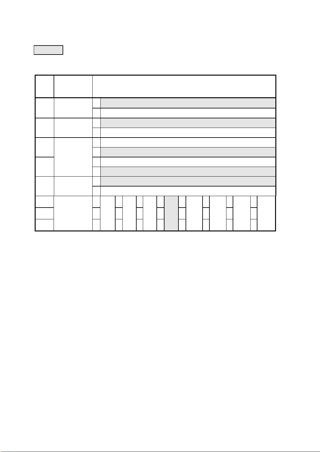
QQQQ Software DIP Switch Setting List
: Factory settings
DIP switch 1
Posi
Function Setting
-tion
bit8
Serial
control
bit7 Stop bit
bit6
Parity
bit5
bit4 Bit length
bit3
bit2
Baud rate
(bps)
bit1
: This setting is enabled only when Serial is selected as the transmission mode with
*1
DIP switch 2.
When BHT Ir is selected as the transmission mode with DIP switch 2, the baud rate
is set to 2400 bps automatically.
: This setting is enabled only when BHT Ir is selected as the transmission mode with
*2
DIP switch 2.
When Serial is selected as the transmission mode with DIP switch 2, the baud rate
is set to 9600 bps automatically.
1 Busy control
0 Xon/Xoff control
1 1 bit
0 2 bits
1Even
Odd
0
1Yes
No
0
1 8 bits
0 7 bits
0
0
00
*1
0110 0
1200124000480019600
01 1
0
0
19200
11
*2
11
384000576001115200
1
*2
- 20 -
Page 24
DIP switch 2
Posi-
Function Setting
tion
Initial status
bit8
automatic
transmission
Kanji
bit7
encoding
system
bit6 Font size
bit5
Auto power
off
bit4 Character set
bit3 Auto loading
bit2 0 0 1 1
bit1
Transmission
mode
selection
1 Disabled
0 Enabled
1 JIS code
0 Shift JIS code
1 24-dot
0 16-dot
1 Disabled
0 Enabled
1 Katakana character
0 Extended graphics
1 Enabled
0 Disabled
BHT Ir
0
Serial
1
IrDA
0
DIP switch 3
Automatic
selection
1
Posi-
tion
Function Setting
bit8 Not used 1 Fixed at "1"
bit7 0011
bit6
bit5 000011
bit4 001100
bit3
bit2 0011
bit1
Print density
Paper
selection
*1
Paper mode
- 5%
0
Thick
paper
(125 µm)
0
Cut sheet
0
1
1
Thick
paper
(145 µm)
1
Standard
Normal
paper
0
Roll paper
+ 5%
0
High
proof
paper
1
Marked roll
paper
0
+ 10%
1
2-ply
thermal
paper
0
*2
1
Reserved
1
Reserved
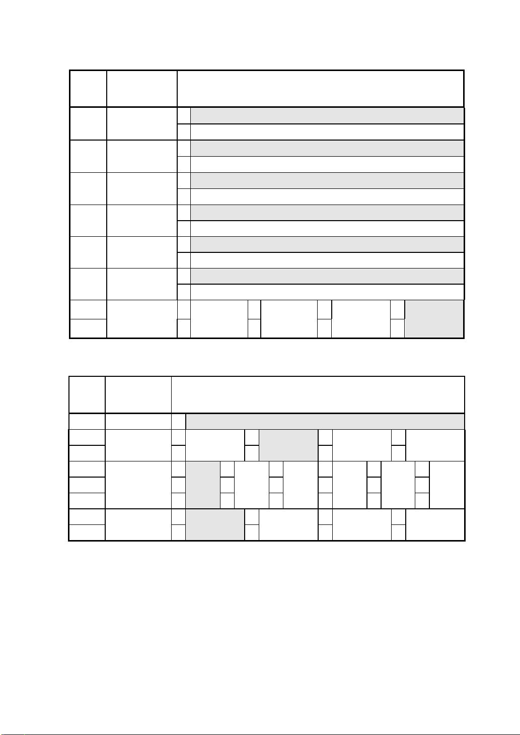
*1 If a setting not listed above is specified, thick paper (125 µm) is selected.
See Section 12, Options and Consumable Parts, for details of papers.
*2 For details, see DPU-3445-20 THERMAL PRINTER TECHNICAL REFERENCE.
- 21 -
Page 25
7
CONNECTING TO THE HOST COMPUTER
This printer supports serial transmission through an interface cable and infrared
transmission. The transmission mode is selected according to the software DIP
switch setting at power on. When automatic selection is set as the transmission
mode by the DIP switch 2, the printer checks whether an interface cable is connected
to the printer when it is turned on. If the interface cable is connected, the printer uses
serial transmission. If not, the printer ignores the setting and uses infrared
transmission.
An interface cable is required to perform serial transmission. An interface cable that
fits into the host computer must be selected. See Section 11, Specifications, for
details of interface specifications.
QQQQ Serial Transmission with an Interface Cable
CAUTION
When plugging or unplugging the interface cable, hold the connector,
not the cable.
When removing or installing the interface cable, turn the printer off.
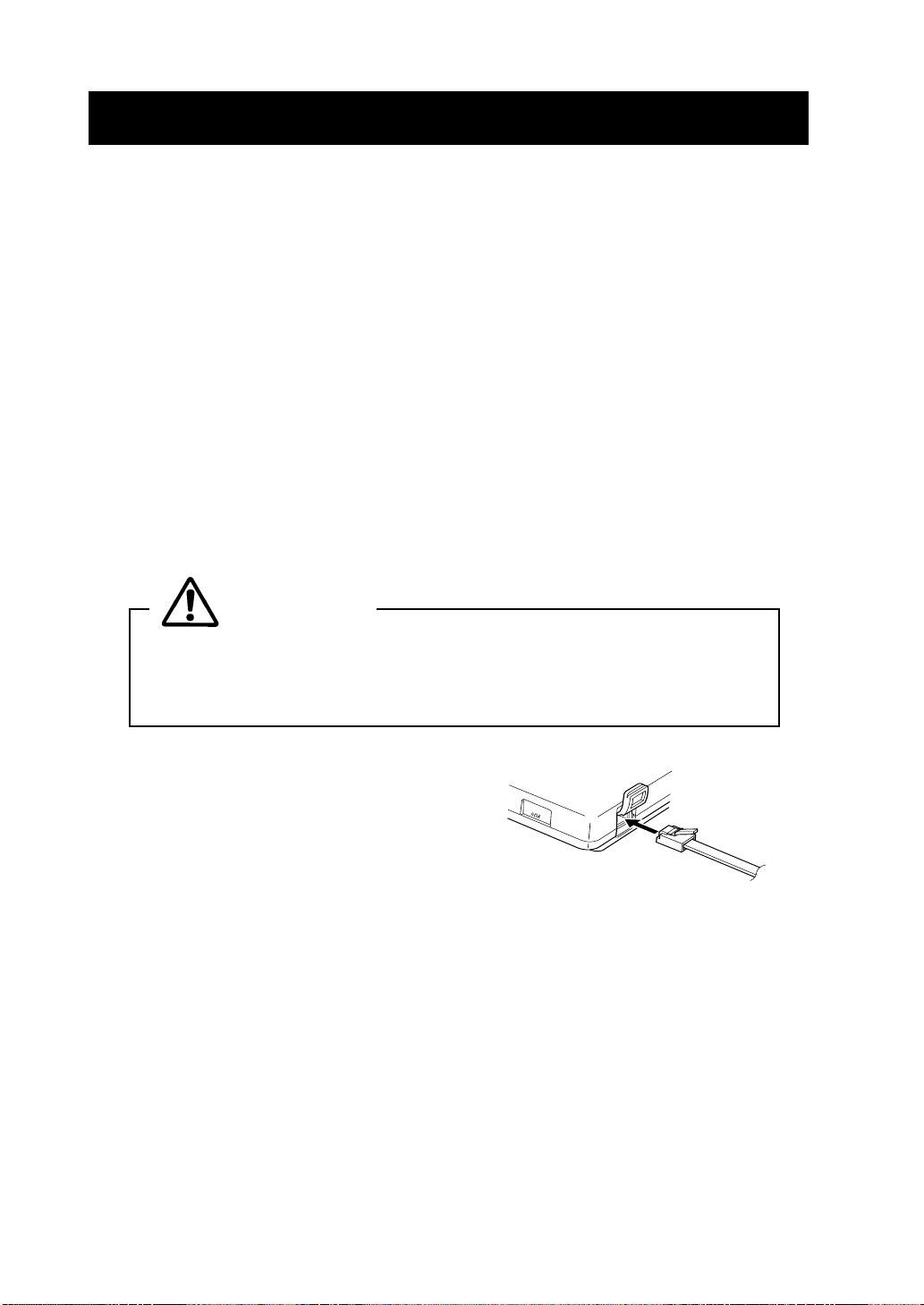
(1) Turn the printer off.
(2) Open the interface connector cover and
connect the interface cable.
(3) Turn the printer on and send data from the host computer to the printer.
(4) Verify that the data is printed correctly.
(5) The interface cable connector has a lock. To remove the cable, pull it out, while
holding the connector hook.
- 22 -
Page 26
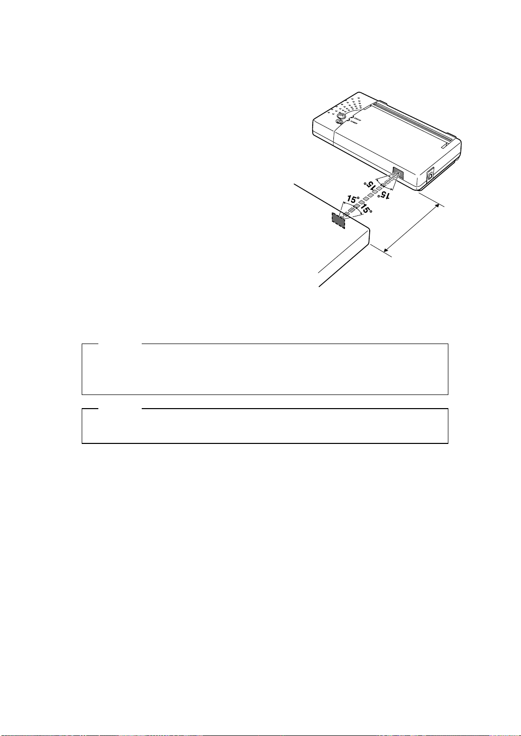
QQQQ Infrared transmission by IrDA
(1) Turn the printer off.
(2) Turn the printer on without connecting the
interface cable to it.
(3) Place the infrared transmitter/receiver of
the host computer and the infrared
transmitter /receiver of the printer as
shown in the figure.
(4) Check the transmission status from the
host computer.
(5) Send data from the host computer to the
printer. Verify that the printer prints it
correctly.
HINT
Within 50 cm
• The positions shown in the figure are for reference. The best positions
depend on the model and environmental conditions.
NOTE
The host computer must conform to IrDA (Ver. 1.0) or BHT Ir protocol.
- 23 -
Page 27

8 RECHARGING THE BATTERY PACK
The battery pack is partially charged prior to shipping, and provides sufficient power
to check the printer operation. To use the printer for an extended time, fully recharge
the battery pack.
This battery pack does not need to be used up or discharged before recharging.
The battery pack can be recharged when it is installed in the printer connected with
an AC adapter. The battery pack can also be recharged with exclusive battery
charger.
QQQQ Recharging the Battery Pack in the Printer
An AC adapter and a power cable are required to recharge the battery pack in the
printer.
(1) Remove the interface cable from the connector and turn the printer off.
(2) Install the battery pack in the printer.
(3) Connect the AC adapter to the printer.
(4) Connect the AC cable to the AC adapter and insert the AC plug of the AC cable to
a wall outlet.
(5) Hold down the POWER button for five seconds. The POWER lamp lights and
starts blinking. When the lamp starts blinking, recharging begins.
(6)The POWER lamp will continue to blink while recharging. When recharging is
complete, the POWER lamp lights continuously. At this time, when the paper is
not set or the platen cover is opened, the ERROR lamp lights. The recharging time
depends on the ambient temperature and the voltage level of the battery pack.
Normally, it takes about 4 to 5 hours to recharge a battery pack.
NOTE
DO NOT remove the battery during recharging. If it is removed during
recharging, remove the AC plug from the outlet immediately. Never
touch the battery terminal. Remove the interface cable from the
connector during recharging.
HINT
• The printer cannot print or receive data while it is recharging the
battery pack. It is convenient to purchase exclusive battery charger or
another battery pack.
• To stop recharging, press the POWER button. The printer will turn off.
To recharge the battery pack again, repeat the steps shown in (1).
• The battery pack should be recharged at 10 to 30°C for optimum
performance.
- 24 -
Page 28
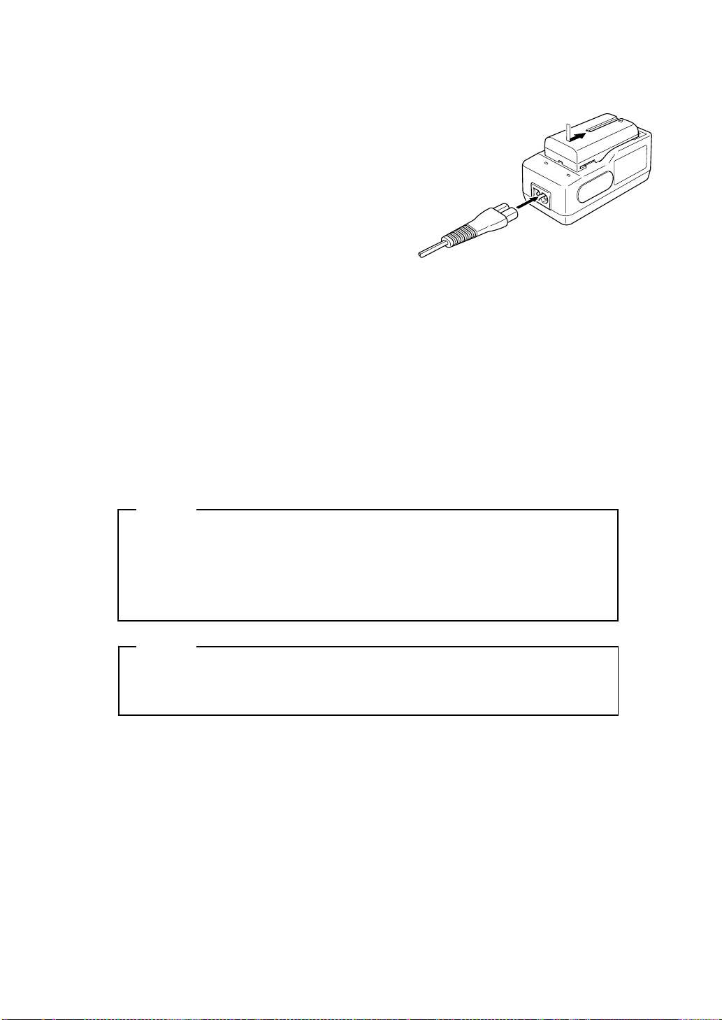
QQQQ Recharging with Exclusive Battery Charger
(1) Install a battery pack in the charger. Push the
battery pack into the charger and slide it in
the direction of the arrow. Push in the battery
pack until the charger shutter is hidden.
(2) Connect the power cable to the charger and
insert the AC plug of the AC cable to a wall
outlet. The charger CHARGE lamp (orange)
will light and the charger will start recharging.
(3) When the CHARGE lamp goes off, the
battery pack is sufficiently recharged for use
(practical recharging). When the battery pack
is recharged for an additional hour, then it is
fully recharged.
(4) When recharging is complete, remove the
battery pack. To remove the battery pack,
slide it in the opposite direction of that for
installation.
(1)
(2)
NOTE
When the charger is connected to the outlet, do not bring any metal
object into contact with the metal terminal.
When the charger is used, remove it from the outlet. Remove the
recharged battery pack from the charger within 24 hours.
HINT
The battery pack should be recharged at 10 to 30°C for optimum
•
performance.
- 25 -
Page 29
9 THERMAL HEAD MAINTENANCE
The thermal head of this printer does not require user maintenance.
If paper dust accumulates, clean the thermal head to maintain maximum print quality
for an extended time.
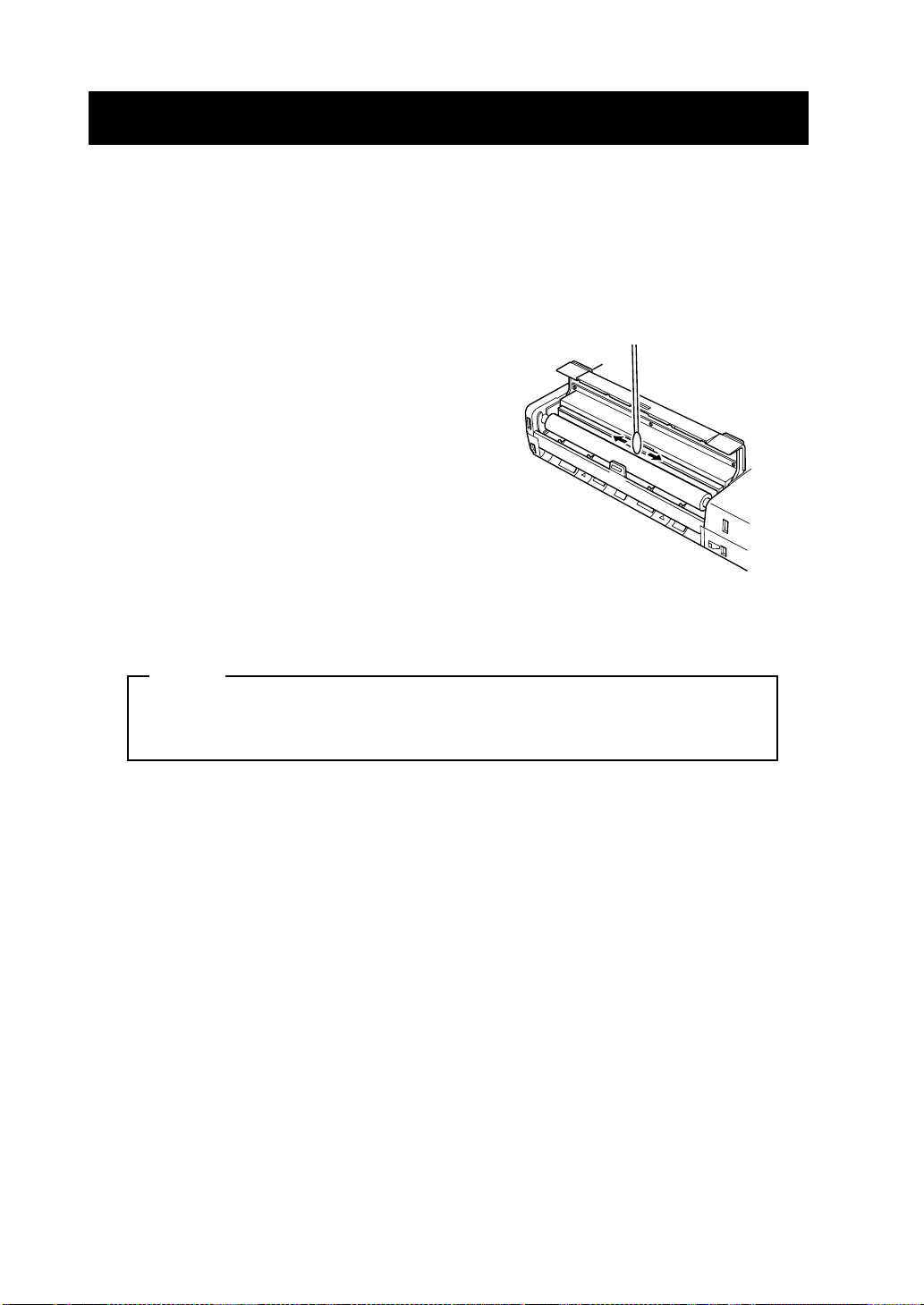
QQQQ Cleaning the Thermal Head
(1) Turn the power off.
(2) Open the platen cover. When the platen cover
is fully opened, the thermal head moves away
from the platen roller.
(3) Clean the thermal head with a cotton swab
moistened with a small amount of ethyl
alcohol.
(4) Wait until any ethyl alcohol remaining on the
thermal head and the platen roller evaporates completely, then close the platen
cover.
NOTE
Clean the thermal head after it cools.
Wipe the thermal head with a cotton swab or other soft material.
- 26 -
Page 30

10 TROUBLESHOOTING
Check the following points before you make a request for repair.
QQQQ The power does not turn on.
· Is the recommended AC adapter or battery pack being used ?
· Are the AC cable and AC adapter connected correctly ?
· Is the AC adapter connected to the printer correctly ?
· Is the battery pack fully recharged?
QQQQ The printer does not print.
· Is the interface cable connected correctly ?
· Is the interface cable that meets the Interface Specifications listed on page 28 of
the User’s Guide being used ?
· Is the IrDA transmission status good ?
· Are the transmission conditions for the printer and the host computer correct ?
· Is the recommended paper being used ? Is the paper orientation (top/bottom)
correct ?
QQQQ The ERROR lamp is lit or the POWER lamp blinks.
· See the Lamp Display on page 9.
· Is the printer function setting correct ?
QQQQ The battery pack Is not installed.
· Is the battery pack correctly oriented ?
· Is the correct battery pack being used ?
QQQQ The battery runs out soon even if recharged.
· Has the battery been recharged correctly ?
· If the battery pack is recharged correctly, but does not last for a long time, it is
almost dead. Replace it with a new one.
- 27 -
Page 31
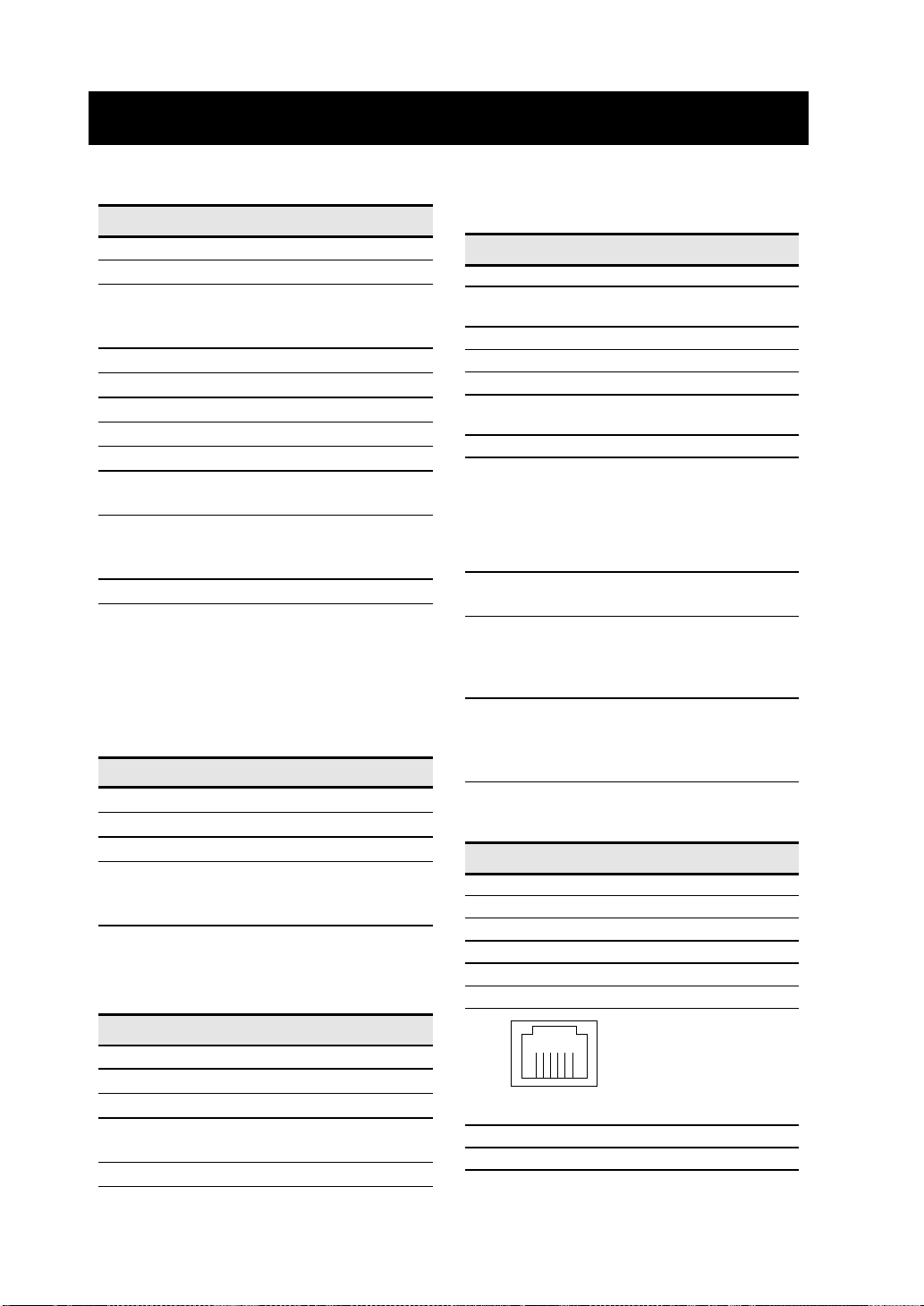
11 SPECIFICATIONS
QQQQ Printer Specifications
Item Specification
Printing method Thermal
Characters per line 52
Character size
(H × W) Standard size: 24 dots × 12 dots
(H × W) Kanji size: 24 dots × 24 dots
Dots available 832 dots
Dot density 8 dots/mm
Printing width/paper width 104/112mm
Printing speed 50 mm/s maximum
Operating temperature 5°C to 40°C
Related humidity 30% to 80%
(no condensation)
Dimensions (W × D × H)
160 × 89 × 29.5mm
(with paper holder) 160 × 164.2 × 59mm
Weight Approx. 250 g (main unit only)
*1
Standard size characters, 4 dots
between characters
*2
Excluding projections
QQQQ Battery Pack
(BP-3007-A1)
Specifications
Item Specification
Battery Lithium ion
Rated voltage 7.2 VDC (Max. 8.4 V)
Rated capacity 1500mAh
Operating temperature
-10°C to 60°C (discharging)
0°C to 40°C (recharging)
QQQQ AC Adapter
(PW-3009-W2)
Specifications
1
*
(Option)
(Option)
QQQQ Battery charger
Specifications
Item Specification
Input voltage 100 - 240 VAC, 50/60 Hz
Output capacity 10 W (recharging 100 V)
Rated output DC8.4V,0.6A
Specified battery BP-3007-A1
Operating temperature 0°C to 35°C
Dimensions (W × D × H)
Weight Approx. 120g
*1
Excluding power cable
QQQQ Interface Specifications
*2
Serial interface
·
Printer connector:
Interface cable connector:
Printer: Modular plug, 6 pins, 6
Host computer:
Interface cable:
Shielded cable with Ferrite core
1.8 m (length)
(recommended)
· Connector signals
Pin Signal
1RXD
2TXD
3BUSY
4 CHK
5SG
6FG
17 W (recharging 240 V)
56 × 107× 44mm
Modular jack, 6 pins
HJC0295 (HOSHIDEN)
conductors
Depends on model type.
(BC-3008-W1)
(Option)
*1
*1
Item Specification
Input voltage 100 - 240 VAC, 50/60 Hz
Output capacity 9.3 VDC, 3A
Operating temperature 0°C to 40°C
Dimensions (W × D × H)
128 × 49 × 25.4mm
Weight Approx. 200g
*1
Excluding power cable
*1
*1
- 28 -
654321
on the printer side
Infrared transmission
·
IrDA Ver. 1.0 based
BHT Ir protocol based
Page 32

12 OPTIONS AND CONSUMABLE PARTS
QQQQ Options
Name Model
Paper holder RH-48-00
Battery pack BP-3007-A1
AC adapter PW -3009-W2
Battery charger BC-3008-W1
AC cable (Japan)* CB-A01-J1
AC cable (North America)* CB-A01-U1
(For exclusive battery charger)
AC cable (North America)* CB-A02-U1
(For AC adaptor)
AC cable (Europe)* CB-A01-E1
* The shape of the power outlet differs from
country to country. Please confirm before
use.
The AC cable can be used both for the AC
adapter and exclusive battery charger.
(Does not apply to those exported to the
U.S.)
QQQQ Paper
Name Model
(Specification)
Thick paper (125 µm) TS-341-125
(112 mm (width) x 158 mm (length);
cut sheets)
Thick paper (145 µm) TS-341-145
(112 mm (width) x 158 mm (length);
cut sheets)
Normal paper TP-341L-1
(112 mm (width), 48mm diameter roll)
High proof paper TP-343L-3
(112 mm (width), 48mm diameter roll)
2-ply thermal paper* TP-345L
(112 mm (width), 48mm diameter roll)
If the recommended paper is not used,
the print quality or the thermal head life
may be below product specifications.
* The 2-ply thermal paper should be used at
5 to 35°C.
- 29 -
Page 33

Seiko Instruments Inc.
8, Nakase 1-chome, Mihama-ku
Chiba-shi, Chiba 261-8507, Japan
Print System Division
Telephone:+81-43-211-1219
Facsimile:+81-43-211-8037
Seiko Instruments USA Inc.
Micro Printer Div.
2990 W. Lomita Blvd., Torrance CA 90505, USA
Telephone:+1-310-517-7778 Facsimile:+1-310-517-8154
Seiko Instruments GmbH
Siemensstrasse 9b D-63263 Neu-lsenburg, Germany
Telephone:+49-6102-297-0 Facsimile:+49-6102-297-116
Seiko Instruments (H.K.) Ltd.
4-5/F, Wyler Centre 2,200 Tai Lin Pai Road, Kwai Chung, N.T., Kowloon,
Hong Kong
Telephone:+852-2421-8611 Facsimile:+852-2480-5479
Seiko Instruments Taiwan Inc.
4F, No.40, Sec. 2, Min-Chuan E.Rd,.Taipei 104, Taiwan, R.O.C.
Telephone:+886-2-563-5001 Facsimile:+886-2-521-9519
Seiko Instruments Singapore Pte. Ltd.
2, Marsiling Lane Singapore 739144
Telephone:+65-269-1370 Facsimile:+65-269-9729
(Specifications are subject to change without notice.)
 Loading...