


Table of contents
1 General instructions 2
2 Safety regulations 3
2.1 Safety instructions 4
3 Product description 5
3.1 Main parts 5
3.2 Main features 6
3.3 Scope of supply 6
4 Transporting the gun 7
4.1 Transport 7
5 Handling the gun 7
5.1 Preparing the gun 7
5.2 Ammunition 8
5.3 Loading the gun (ready to fire) 8
5.4 Discharging a shot 9
5.5 Reloading during shooting 10
5.6 Unloading the gun 11
5.7 Bolt 11
5.7.1 Cocking the bolt 11
5.7.2 Removing the bolt 12
5.7.3 Inserting the bolt 12
5.7.4 Uncock the firing pin 13
5.8 Magazine 13
5.8.1 Removing the magazine 13
5.8.2 Inserting the magazine 13
5.8.3 Loading the magazine 13
5.9 Trigger 14
5.9.1 Setting the take-up 14
5.9.2 Setting the trigger position 15
5.9.3 Setting the let-off point 15
6 Safety lock 15
6.1 Safety OFF 15
6.2 Lock 16
7 Stock 16
7.1 Removing the cheekpiece 16
7.2 Stock setting options 17
7.2.1 Adjusting cheekpiece offset 17
7.2.2 Adjusting cheekpiece for height 17
7.2.3 Adjusting the buttplate length 17
7.3 Installing the cheekpiece 17
8 Dismantling 18
8.1 Removing the stock 18
8.2 Removing the carrying sling 18
8.3 Removing the barrel 19
9 Assembly 19
9.1 Fitting the barrel 19
9.2 Installing the stock 20
9.3 Fitting the carrying sling 20
10 Training system cal. 22 lr.
(optional) 21
10.1 Caliber conversion cal. 22 lr. 21
11 Accessories 22
11.1 Scopes 22
11.1.1 Installing the scope 22
11.1.2 Removing the scope 22
11.2 Adjusting eye relief length 22
11.3 Removing the mirage band 23
11.4 Installing the mirage band 23
12 Care 24
12.1 General remarks 24
12.2 Cleaning the barrel 24
12.3 External metal surfaces 25
13 Extras 25
13.1 Installation of optional
accessories on the mounting rail 25
14 Dealing with problems 26
14.1 Cause and correction of
malfunctions 26
14.2 Shipping the gun 28
15 Installation of optics and
accessories 28
16 Technical specifications 29
17 Accessories 30
18 Spare parts 30
18.1 SSG 3000 spare parts 31
18.2 Spare parts for training system
.22 lr. (optional) 34
Inhaltsverzeichnis
1 GB 07.01

Instructions
1 General instructions
Be sure to read through these instructions
carefully before any manipulation on this
SAUER gun.
Understanding these instructions and the
technically correct implementation of the
information contained therein are imperative for
the correct preparation and safety during
handling, maintenance and care of this SAUER
gun. Do not use the gun until you have fully
understood all safety instructions and handling
procedures. Should you require further
information, do not hesitate to contact your dealer,
importer or the manufacturer.
Please observe the local and national legislation
governing the ownership, carrying and use of
firearms.
Be aware that this gun, like all firearms, is
dangerous. The gun accompanying these
Handling and Safety Instructions has been sold
under the express understanding that the
manufacturer and the importer of the gun decline
any responsibility for consequences of
manipulations on the gun or use of the gun.
This applies in particular to liability for bodily harm
or damage to property resulting in part or in whole
to:
– use with criminal intent or negligent use,
– improper or careless handling,
– defective, incorrect, hand-charged or
recharged ammunition,
– inadequate care of the gun
(e.g. corrosion, damage),
– disregard of malfunctions,
– resale in contradiction of regional legislation
and regulations,
– other circumstances beyond our direct and
immediate control.
These limitations apply regardless of whether
liability is asserted on the basis of contract,
negligence or strict liability (including any failure to
warn).
The manufacturer and the importer are not liable
for incidental or consequential damages such as
loss of use of property, commercial loss or loss of
earnings and profits.
2GB07.01

Safety regulations
2 Safety regulations
•
Never use the gun under the influence of
alcohol or drugs, during illness or other
complaints; they may influence your
judgement and reflexes.
• Always treat the gun as loaded and unlocked
until you have made sure to the contrary by
unloading it.
• During all manipulations, keep the muzzle of
the gun pointed in a safe direction. Safe
directions are defined as areas where there
are no people, other living creatures or other
people's property.
• Never point the gun at doors, window panes,
walls, concrete, stones or other flat surfaces
(including water). Shots can penetrate such
surfaces or be deflected into unsafe directions
by them.
• Never aim at yourself or other people.
• Never rely on safety mechanisms. They are
never a substitute for careful and correct
handling of the gun.
• Always handle your gun as if the safety
mechanisms were not functional. The best
safety device is the correct, well-exercised and
secure handling of the gun.
• Never shoot a gun into which there has been
ingress of water, sand, dirt or other foreign
bodies.
• Never release the tension on the firing pin
merely by pulling the trigger.
• Never let a loaded gun out of your hands.
• Always unload the gun immediately after
shooting, before putting it down, putting it in its
case or handing it to another authorised
person.
• Never hand the gun to any person who has not
thoroughly familiarised himself or herself with
the safety regulations and handling of the gun
by reading the accompanying instructio n s .
• Never leave the gun lying around unattended.
Unauthorised persons can cause damage or
threaten or kill people with it, for which you
might be liable.
• Never store the gun loaded, but remove the
magazine and verify through unloading there is
no round in the barrel chamber.
• Always keep the gun and the ammunition in
different places and ensure that neither can fall
into the hands of unauthorised persons or
children.
3 GB 07.01
Safety regulations
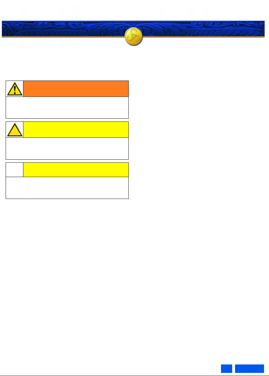
2.1 Safety instructions In the individual sections of these
instructions, the following safety indications
alert you to various risks:
WARNING!
Information on risks which, if not scrupulously
observed, can lead to severe bodily harm or
death.
CAUTION!
Information on risks which, if not scrupulously
observed, can lead to bodily harm or damage to
the gun.
CAUTION!
Information on technical requirements which, if
not scrupulously observed, can lead to damage
to the gun.
• Each safety indication consists of:
– a header with a signal word, icon and a
corresponding colour shading
– a specification of the type and source of the
risk
– a specification of potential consequences if
the safety indications are not observed
– specifications of measures and prohibitions
designed to avoid risks
4GB07.01
Product description
3 Product description
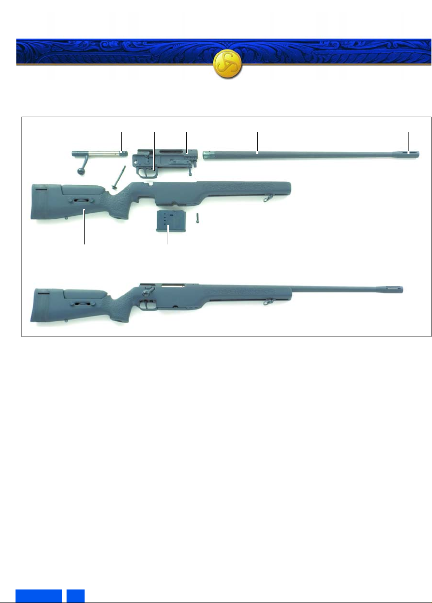
3.1 Main parts
100
500
Abb. 1, SSG 3000 with McMillan plastic stock
Pos. Description Pos. Description
100 Bolt 500 Stock
300 Magazine tube 600 Magazine
400 Barrel 700 Trigger mechanism
402 Flash suppressor
300 400 402700
600
5 GB 07.01
Product description
3.2 Main features
The SAUER SSG 3000 precision rifle is a manual
type repeating rifle developed to meet the specific
requirements of law-enforcement and military
sharp-shooters.
The modular design concept allows primary
components such as the receiver, barrel, trigger
system, stocks and bolt to be rapidly and readily
exchanged. Consequently, maintenance logistics
are both simple and efficient.
The SSG 3000 is an easily handled repeating rifle
featuring a double stage trigger pattern. Integrated
mounts permit immediate and secure fitting of a
wide variety of sighting equipment.
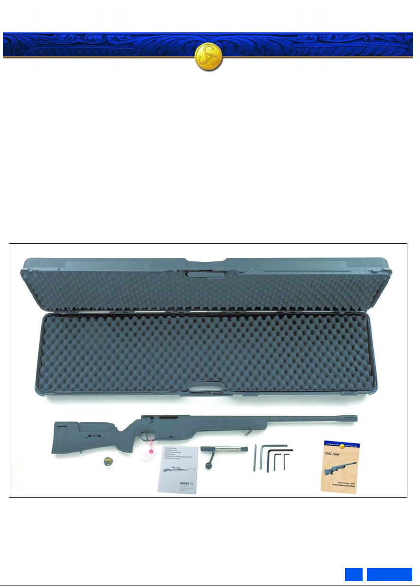
3.3 Scope of supply
The standard scope of delivery includes:
– 1 x gun
– 1 x magazine
– 4 x Allen key
– 1 x Allen spanner
– 1 x Handling and Safety Instructions manual
– 1 x 10 g SAUER Premium gun grease
– 1 x SAUER plastic case
– Warranty card
Abb. 2, Standard scope of supply
6GB07.01
Transport Handlin
g
4 Transporting the gun
4.1 Transport
WARNING!
Uncontrolled discharge of shot
May lead to death or severe injuries
• When transporting your firearm, always keep
it unloaded (see section 5.6) and decocked
for your own safety and for the safety of
others.
• Never carry a cocked gun containing a round
in the barrel chamber.
• Always carry the gun in such a manner that,
should you fall or otherwise slip, you are able
to control the direction of the muzzle.
• Transport the gun separate from the
ammunition in a locked carrying case.
• The gun and ammunition must be out of the
reach of children and other inexperienced or
unauthorized persons.
• Ensure that you comply with all regional and
national laws relating to the transport of
firearms.
5 Handling the gun
5.1 Preparing the gun Note:
The gun is supplied with a protective and
preserving oil and grease coating, and excessive
protective oil and grease must be removed prior to
first commissioning.
The SSG 3000 and its accessories are packed in
a rugged carrying case to protect them against
impact.
For safety reasons the bolt and the magazine
must not be inserted during:
– first commissioning and
– taking possession of the gun.
WARNING!
Undefined condition of the gun
May lead to death or severe injuries
• If the shooter takes possesion of the gun in
any other condition it must be treated as
loaded and unlocked.
Procedure:
1. Unload the gun (see section 5.6).
2. Remove the bolt (see section 5.7.2).
3. Check whether ammunition is still in the barrel
chamber or in the magazine.
4. Clean the barrel (se e section 12.2).
5. During first commissioning:
– Clean external metal surfaces
(see section 12).
7 GB 07.01
Handling
5.2 Ammunition 5.3 Loading the gun (ready to fire)
WARNING!
Incorrect ammunition
May lead to death or severe injuries and
damage to the gun
• Only fire commercially available ammunition
in the original packaging and of the correct
caliber from this gun.
• Never use recharged, "reconditioned", hand-
charged or non-standard ammunition in your
gun.
• Never use dirty, wet, corroded, bent,
damaged or oiled ammunition.
• Never spray lubricants, preservatives or
cleaning agents directly onto the rounds.
• Never leave the ammunition lying around
unattended.
WARNING!
Insufficient awareness of the dangers
May lead to death or severe injuries
• Never load or unload the gun inside a vehicle,
inside a building or any other confined space
(except in a designated firing range).
• Before loading, always wipe off any excess
grease and oil and check that there is no
obstruction in the bore of the barrel.
• Always keep the muzzle of the gun pointed in
a safe direction.
• Do not place the finger onto the trigger, but
outside the trigger guard.
• Do not load the gun by inserting the
magazine until immediately before shooting.
• Never rely on safety mechanisms. They are
never a substitute for careful and correct
handling of the gun.
• Never let a loaded gun out of your hands.
8GB07.01
Handling
Procedure:
1. Lock the gun (see section 6.2).
2. Insert the bolt (see section 5.7.3).
3. Unlock the gun (see section 6.1).
4. Open the bolt and pull it back to the stop.
5. Fill the magazine (see section 5.8.3).
Note:
• If the full load capacity of the gun is to be used,
chamber a round and close the bolt prior to
inserting the magazine. Only now insert a full
magazine.
6. Insert the magazine (see section 5.8.2).
7. Push the bolt forward and lock.
8. Lock the gun (see section 6.2).
The gun is loaded and ready to fire.
5.4 Discharging a shot
WARNING!
Insufficient awareness of the dangers
May lead to death or severe injuries
• Ensure that the target and the environment
allow shots to be fired without danger.
• When discharging shots, ensure that your
hands or any other parts of the body are
located in front of, over or adjacent to the
barrel muzzle or the ejection port.
• Never allow other persons to stand beside
you where they might be struck by ejected
cartridge cases.
• Always wear ear protection and safety
glasses when shooting. Alert bystanders to
the importance of wearing ear protection.
• Immediately stop shooting and unload the
gun if you suspect that a round has not been
chambered properly, a case is jammed, a
bullet is lodged in the bore or a discharge
sounded or felt weak or abnormal.
• Never attempt to dislodge a blockage in the
barrel by firing another round.
9 GB 07.01
Handling
Procedure:
1. Aim the gun at a safe target.
2. Unlock the gun (see section 6.1).
3. Place finger on trigger and pull back the trigger
to discharge the shot.
4. Keep the gun aimed at the target and repeat
and fire further shots as required.
5. If the magazine is empty, reload the gun (see
section 5.5).
6. Lock and unload (see section 5.6).
WARNING!
Gun is ready to fire
May lead to death or severe injuries
• If you decide to end the shooting session,
immediately unload the gun.
5.5 Reloading during shooting
WARNING!
Insufficient awareness of the dangers
May lead to death or severe injuries
• Never let the gun out of your hands.
• Keep the gun pointed at the safe target.
Procedure:
1. Lock the gun (see section 6.2).
2. Remove the empty magazine (see section
5.8.1).
3. Unlock the gun (see section 6.1).
4. Open the bolt and pull it back to the stop.
5. Fill the magazine (see section 5.8.3).
6. Insert full magazine and check engagement
(see section 5.8.2).
7. Push the bolt forward and lock.
8. Lock the gun (see section 6.2).
The gun is loaded and ready to fire.
10GB07.01

Handling
5.6 Unloading the gun
WARNING!
Gun is ready to fire
May lead to death or severe injuries
• Never let the gun out of your hands before it
is unloaded.
• The gun is loaded, a round is located in the
chamber of the barrel.
• Never place your hand over the ejection port
of the bolt.
Procedure:
1. Lock the gun (see section 6.2).
2. Aim the gun at a stop-butt.
3. Remove the magazine (see section 5.8.1).
4. Unlock the gun (see section 6.1).
5. Open the bolt.
– The cartridge or cartridge case is pulled out
of the barrel chamber and ejected.
6. Check that the round has been ejected and
there are no more rounds in the barrel
chamber.
7. Empty magazine.
8. Pick up ejected round and clean the gun.
5.7 Bolt
5.7.1 Cocking the bolt
Before the bolt 100 can be inserted into the gun,
the firing pin must first be cocked.
A cocking indicator displays whether the bolt is
cocked or not (red = cocked).
Procedure:
1. Insert the tapered end of the supplied key into
the side opening of the lock 113.
2. Turn the lock towards the cocking wheel until it
engages.
Abb. 3, Cocking the bolt
WARNING!
Gun has not been cleaned sufficiently
May lead to death or severe injuries and
damage to the gun
• The gun must be cleaned after every
shooting session (see section 12.2).
The gun is unloaded.
11 GB 07.01
Abb. 4, Cocking indicator of the bolt (left: cocked, right decocked)

Handling
5.7.2 Removing the bolt Procedure:
1. Move the buttstock cheekpiece down as far as
possible or remove it (see section 7.1).
2. Release the gun safety (see secti on 6.1).
3. Open the bolt and draw it back approx. half of
its travel.
4. Activate the safety catch (see section 6.2).
5. Rotate the bolt to the left (approx . 90°), until
the bolt channel becomes visible in the bolt
handle guideway.
6. Extract the bolt to the rear.
1.
3a
2.
3b.
5.7.3 Inserting the bolt
Procedure
WARNING!
Uncontrolled discharge of shot
May lead to death or severe injuries
• The gun must be unloaded.
Procedure:
1. Move the cheekpiece down as far as possible
or remove it (see section 7.1).
2. Lock the gun (see section 6.2).
3. Cock the bolt (see section 5.7.1).
CAUTION!
Gun may be damaged
• Never use force when inserting the bolt.
4. Insert the cocked bolt into the receiver by
rotating it slightly. The removal position (bolt
handle turned to the left by 90°, see Fig. 5/
5.+6.) is the best position to install the bolt.
CAUTION!
6.
Abb. 5, Removing the bolt
Danger of collision of cheekpiece with
4.
cocking indicator (if the cheekpiece has not
been removed)
• When sliding in the bolt, the cocking indicator
must not face directly downwards.
5.
5. Rotate the bolt until the bolt handle slides into
the guideway of the receiver (see Fig. 5/3b.).
6. Slide the bolt up to the front and lock it.
7. Install or adjust th e buttstock cheekpiece
(see section 7.3).
Firing
12GB07.01

Handling
5.7.4 Uncock the firing pin
WARNING!
Uncontrolled discharge of shot
May lead to death or severe injuries
• Only uncock the firing pin with the gun
unloaded and the barrel chamber empty.
Procedure:
1. Unload the gun and make sure that there is no
round or cartridge case in the barrel chamber
or in the magazine (see section 5.6).
2. Pull the trigger and slo wly close the bolt with
the trigger still pulled.
Note:
• The cocking indication must not be visible
(see Fig. 4).
5.8 Magazine
5.8.1 Removing the magazine
Procedure:
1. Hold magazine 600 by hand.
2.
CAUTION!
311
Abb. 6
5.8.2 Inserting the magazine Procedure:
1. Insert the magazine into the magazine well
and push it home until the magazine catch 307
audibly engages. Do not jam the magazine.
5.8.3 Loading the magazine
Procedure:
1. Depress magazine feeder 602.
2. Insert the rounds forward and under the
magazine lips.
602
Magazine may fall out
Magazine may be damaged
• When removing the magazine always keep
your hand exactly underneath the magazine.
3. With the index finger of the same hand,
depress pressure bolt 311.
4. Remove magazine.
5. Empty magazine.
13 GB 07.01
Abb. 7

Handling
5.9 Trigger
The SSG 3000 features a trigger with let-off point.
Note:
• The trigger pull weight has been set to approx.
15 N (1.500 g) at factory.
The match trigger is a let-off point trigger with
adjustable take-up.
– The trigger must be pulled until it reaches a
noticeable resistance (trigger let-off point).
– The shot is fired after the resistance has been
overcome.
WARNING!
Uncontrolled discharge of shot
May lead to death or severe injuries
• For safety reasons the trigger pull weight
must only be modified by a qualified
gunsmith. He can adjust the trigger pull
weight between approx. 13 N (1.300 g) and
17 N (1.700 g).
• Any screws sealed with red varnish must not
be adjusted by the user. If these screws are
manipulated, the warranty will be void.
711
709b709a 710
Abb. 8
CAUTION!
Gun may be damaged
• The screw for reducing the take-up must only
be turned clockwise to a degree that the
safety lock will still work properly.
• If the free movement of the safety lock is
impeded, the screw must be immediately
turned back anti-clockwise until the normal
safety lock function is restored.
5.9.1 Setting the take-up Reduce take-up: – Turn set screw 709b clockwise. Increase take-up: – Turn set screw 709b anticlockwise.
Note:
• When setting the take-up, the trigger must be
in a position that allows access to set screw
709b.
• The take-up travel cannot be adjusted to
"zero", there will always be a travel by design.
14GB07.01

Handling Safety loc
k
5.9.2 Setting the trigger position
Refer also to Fig. 8.
The trigger 710 can be displaced along the
longitudinal axis by set screw 711.
Procedure:
1. Slacken off set screw 711.
2. Shift the trigger 710 to the desired position.
3. Tighten the screw 711.
Caution:
• Ensure that in the foremost position, the trigger
does not contact the unlock slide 708.
• In the rearmost position, the trigger may not be
located more to the rear, if the trigger begins to
cover the adjusting screw 709a. Otherwise this
could hinder the correct function of the trigger
action; in the worst case, firing a shot is not
possible anymore.
5.9.3 Setting the let-off point
Earlier let-off:
– Turn set screw 709a clockwise.
Later let-off:
– Turn set screw 709a anticlockwise.
Note:
• To be able to adjust the let-off point, the trigger
710 must be in a position that allows access to
set screw 709a.
6 Safety lock
The SAUER SSG 3000 safety system is an
indirect firing pin safety mechanism.
It locks the trigger, the trigger stop, and the firing
pin shoe and thus blocks all safety-relevant
components.
Its function is based on a principle proven a million
times over: A single function – a single button.
– The unlock slide is located within the trigger
guard ahead of the trigger where it is both well
protected and tactile.
– The safety lock is located on the receiver side
behind the bolt handle, where it is both visible
and easy to operate.
6.1 Safety OFF Procedure:
1. Slide the unlock slide 708 up to the stop with
your trigger finger.
– The safety slide 313 slides also upwards
and exposes a visible red warning mark.
Note:
Gun unlocked:
– Safety lock up
– Red mark visible
708
313
Abb. 9, Gun unlocked:
15 GB 07.01

Safety lock Stock
6.2 Lock Procedure:
1. Press down the safety lock 313 up to the stop
with your thumb.
– This causes the unlock slide 708 to slide
downwards out of the trigger unit where it is
easily controlled by the trigger finger.
Note:
Gun locked:
– Red mark not visible
– The unlock catch can be felt with the trigger
finger
.Stock
708
313
Abb. 10, Gun locked
7 Stock
The cheekpiece of the SSG 3000 stock is
adjustable for height and offset and can be
completely removed. The buttplate can be
adjusted in length.
.
Abb. 11
7.1 Removing the cheekpiece Procedure:
1. Unscrew the screws 531 very far or remove
them.
2. Turn the knurled screw 527 to remove the
cheekpiece.
.
Abb. 12
531531 527
16GB07.01

Stock
7.2 Stock setting options
7.2.1 Adjusting cheekpiece offset Procedure:
1. Release screws Fig. 13/A (approx. four turns).
2. Slide cheekpiece to the left or to the right or
jam it as required.
3. Tighten the screws Fig. 13/A well.
.
A A
Abb. 13
7.2.2 Adjusting cheekpiece for height
1. Slacken off locking screws 531.
2. Set the desired hei ght level with adjustment
nut 527.
3. Tighten the locking screws 531 well.
.
7.2.3 Adjusting the buttplate length
1. Unscrew screws 515.
2. Pull buttplate 516 back a little.
3. Press spacers 519 towards the left on the top
and turn them downwards for removal.
4. Extract the spacers to the bottom.
5. Tighten screws 515.
CAUTION!
Gun may be damaged
• Do not overtighten screws 515 as otherwise
the escutcheons will be torn out of the stock.
.
519515519 516
Abb. 15
7.3 Installing the cheekpiece
Procedure:
1. Position the cheekpiece on the stock.
2. Adjust the cheekpiece for height (see section
7.2.2) and offset (see section 7.2.1).
3. Tighten the locking screws 531 well.
531531 527
Abb. 14
17 GB 07.01

Dismantling
8 Dismantling
WARNING!
Gun is ready to fire
May lead to death or severe injuries
• There must be no magazine in the gun.
• Before stripping your gun, ensure once again
that it is unloaded (see section 5.6).
8.1 Removing the stock Procedure:
1. Open the bolt and remove it
(see section 5.7.2).
2. Slacken off and remove the rear 514 and front
512 stock retention screws.
3. Remove the filler piece 511 from the magazine
stock.
4. Lift the system out of the stock.
8.2 Removing the carrying sling Procedure:
1. Unscrew the knurled knob Fig. 17/A to the left.
2. Press in the knurled knob with the plunger and
twist it by 90° to the left.
3. Remove the sling swivel.
A
Abb. 17, Sling swivel bushing
Note:
• Clean and oil the sling swivels regularly.
Abb. 16
514 512511
18GB07.01

Dismantling Assembl
y
8.3 Removing the barrel Procedure:
1. Use the spanner supplied to slacken off the
clamping screws 306, 306a in the sequence
centre - rear - front.
2. Completely undo the front clamping screw
306a only.
3. Pull out insert 308 from below.
4. Extract the barrel 400 from the receiver by
lightly twisting it if required.
306 306a
308
Abb. 18
d
400
9 Assembly
CAUTION!
Gun may be damaged
• Only assemble cleaned gun parts.
9.1 Fitting the barrel
CAUTION!
Gun may be damaged
• Do not use force when inserting the barrel
into the magazine tube.
• Tighten the clamping screws until the
spanner supplied begins to flex slightly.
• The spanner must not be extended by
attaching a tube.
• If a torque spanner is used to tighten the
screws, apply 7-8 Nm.
Corresponding figure, see Fig. 18.
Procedure:
1. Insert the barrel 400 from below up to the stop
into the clamping device. Ensure that the
barrel is aligned in such a way that the insert
remains easy to move all the time.
2. Place insert 308 from below up to the stop into
the receiver.
3. Turn the barrel until the insert engages in the
barrel groove.
4. Install clamping screw 306a.
5. Lightly tighten clamping screws 306, 306a.
6. Install and close the bolt (see section 5.7.3).
7. Check the bolt acti on with the gun unloaded.
8. Alternatively tighten the clampi ng screws 306
and 306A a little more so that the barrel is
fixed without tension (alternative: tightening
with a torque spanner: torque 7-8 Nm).
19 GB 07.01

Assembly
9.2 Installing the stock
CAUTION!
Gun may be damaged
• The spanner must not be extended by
attaching a tube.
• If a torque spanner is used to tighten the
stock retention screws, apply 5 Nm.
Corresponding figure, see Fig. 16
Procedure:
1. Lightly turn the rear stock retention screw 514
by hand.
2. Lightly turn the rear stock retention screw 512
by hand.
3. Tighten rear stock retention screw 514.
4. Tighten front stock retention screw 512.
Note:
• Correct torque for the stock retention screws is
achieved by grasping the end of the spanner
and applying enough twist to raise the gun into
the vertical position.
9.3 Fitting the carrying sling
Corresponding figure, see Fig. 17.
Procedure:
1. Insert the open sling swivel.
2. Press the knurled knob with the plunger and
turn it to the right until the hinged plate snaps
onto the stud.
3. Remove the knurled knob from the plunger by
turning it to the right.
4. Insert the stud of the front sling swivel also into
the front sling swivel bushing 48.
Note:
• Securely tighten the knurled knob on the
plunger prior to turning.
• The sling swivel must be aligned exactly 90° to
the orientation of the barrel.
20GB07.01

Training system
10 Training system cal. 22 lr.
(optional)
10.1 Caliber conversion cal. 22 lr. Procedure:
1. Remove barrel (see section 8.3)
.
301
Abb. 19
2. Remove magazine ejec tor. Unhook the
magazine ejector spring 301 downwards from
its upper retainer and allow it to relax.
.
302
Abb. 20
3. Now unhook the lower claw from the magazine
ejector 302 and remove it.
.
302
Abb. 21
4. Lift the bottom end of the magazine ejector,
swing it to the left and remove it from the upper
aperture.
5. With the slot facing downwards, insert barrel
450 into the receiver. Align slot with the slot in
the receiver.
6. Place insert 308 into the receiver from below.
7. Lightly tighten clamping screw 306a and
remove the magazine (see section 5.8.1).
8. Insert the magazine adapter into the magazine
well until it contacts the barrel.
9. Retain magazine adapter with screw 656.
.
656
657
658
Abb. 22
10.Check correct barrel location by lightly rotating
the barrel in both directions.
Note:
• On both sides there should be about the same
gap between the magazine adapter and the
magazine well.
11.Check that the screw 656 is well seated. If
necessary, tighten it.
12.Tighten the clamping screws 306/306a and
install the stock (see section 9.2).
13.Cock the bolt (see section 5.7.1), insert (see
section 5.7.3) and then lock it.
14.Cycle the bolt to check that its action is
smooth.
15.Insert the magazine 658 until it snaps in.
16.Sight in the gun (zeroing).
.
21 GB 07.01

Accessories
11 Accessories
11.1 Scopes
11.1.1Installing the scope
1. Slacken off the Allen screws 204 on the scope
rail 200 until the scope can be slid on.
2. Hold the scope at an angle and parallel to the
rifle.
3. Snap the scope rail 200 from the left side onto
the receiver dovetail.
4. Slide the scope to the front until the scope rail
stop firmly abuts against the receiver housing.
5. Tighten the Allen screws 204.
6. Check that the scope rail stop abuts firmly
against the receiver and that the scope is
securely mounted on the gun.
7. Attach the mirage band (see section 11.4).
11.1.2Removing the scope
1. Remove the mirage band (see section 11.3).
2. Slacken off the two Allen screws 204 on the
scope rail 200.
3. Lift off the scope to the left side.
11.2 Adjusting eye relief length
1. Slacken off the Allen screws 205 until the
scope can be slid along its own axis.
2. Select the desired eye relief length of the
scope.
3. Tighten the Allen screws 204.
656
657
204
Abb. 23
22GB07.01

Accessories
11.3 Removing the mirage band
CAUTION!
The mirage band is only loosely connected
with the gun
May lead to injuries and damage to the gun
• Keep the gun pointed in a safe direction in
order to prevent the mirage band from
injuring persons or damaging property if it
slips unintentionally.
Procedure:
1. Remove the hook of the mirage band from the
forward scope rail mount and relax the mirage
band (see Fig. 24 top).
2. Unhook the twin claws of the mirage band
hook from the holes of the upper central slots
of the flash suppressor (see Fig. 24 below).
11.4 Installing the mirage b and
CAUTION!
The mirage band is only loosely connected
with the gun
May lead to injuries and damage to the gun
• Keep the gun pointed in a safe direction in
order to prevent the mirage band from
injuring persons or damaging property if it
slips unintentionally.
Corresponding figure, see Fig. 24.
Procedure:
1. Insert the twin claws of the mirage band hook
into the hole of the upper central slots of the
flash suppressor.
2. Stretch the mirage band to the rear and slip
hook onto the forward scope mount.
Abb. 24
23 GB 07.01

Care
12 Care
12.1 General remarks
Proper functioning and precision of the gun can
only be maintained through regular and expert
care. The gun must be cleaned and protected
against corrosion after each use. The bore must
be cleaned and protected against corrosion after
each firing. Wooden stocks must be treated with a
suitable agent in accordance with the
corresponding instructions and must be protected
against the weather.
For the optimum care for your SSG 3000 we
recommend SAUER care products, e.g. the
SAUER Premium gun grease.
WARNING!
Gun is ready to fire
May lead to death or severe injuries
• There must be no magazine in the gun.
• Before stripping your gun for cleaning, ensure
once again that it is unloaded
(see section 5.6).
12.2 Cleaning the barrel
CAUTION!
Gun may be damaged
• Never clean the bore from the muzzle end
and never use steel or brass wire brushes as
these can destroy the polished surface of the
bore. Use only suitable cleaning rods and a
brush of the correct caliber.
• Detergents can damage the surface of the
gun. Carefully read the manufacturers note s
and warnings before applying solvents or
cleansers.
Procedure:
1. Unload the gun (see section 5.6).
2. Remove the bolt (see section 5.7.2).
3. Clean the bore and barrel chambe r from the
rear using suitable fluids or grease (observe
the respective instructions for use) and a
suitable bronze or plastic cleaning brush of the
correct calibre.
4. Check for traces of metal fouling (leading) in
the bore. If necessary remove leading with a
commercially available bore cleaning solvent
(read the respective instructions for use).
5. Lightly lubricate the the barrel bore and
chamber with a little gun oil or gun grease.
6. Dry the bore and chamber from the rear using
a plastic coated cleaning rod of the correct
calibre.
24GB07.01

Care Extra
s
12.3 External metal surfaces
For the care and preservation of the external metal
and wood surfaces we recommend SAUER
Premium gun grease. Minute spherical Teflon
particles seal the pores of all wood and metal
surfaces and provide perfect protection and
optimal sliding characteristics.
Benefits:
®
• dry surfaces - dust etc. does not adhere;
• water and salt water proof;
• absolute corrosion protection;
• perfect sliding characteristics, reduced wear;
• resistant to sweaty palms;
• pressure resistant up to 57.000 kg/cm
2
;
• temperature resistant from -50 to +230 °C;
• perfect protection and care for steel and wood;
• neutral smell
CAUTION!
Gun may be damaged
• Caring for the external metal surfaces is
particularly important in wet weather or if the
metal surfaces have come into contact with
sweaty body parts.
• Always wipe dry the gun prior to preservation.
Procedure:
1. Thoroughly clean the gun using suitable cloths
and cleaning agents.
2. Thinly apply the grease with a cloth or sponge
over the whole gun (including the stock)
including all mechanical and moveable parts.
3. After a reaction time of at least 60 minutes
wipe dry and polish the gun with a clean cloth.
4. Dependent on the weather and frequency of
use the protective effect will last between two
to six months.
Note:
• The sling swivel must also be cleaned and
oiled at regular intervals.
13 Extras
13.1 Installation of optional accessories on
the mounting rail
Procedure:
1. Insert accessory into the rear hollow of the
mounting rail and slide it to the front.
2. Position and fix accessories.
25 GB 07.01

Dealing with problems
14 Dealing with problems
14.1 Cause and correction of malfunctions
Gun maintenance (cleaning and inspection)
according to the instructions can prevent
malfunctions.
Should, nevertheless, a malfunction occur during
shooting, proceed as follows:
WARNING!
Uncontrolled discharge of shot
May lead to death or severe injuries
• Hold the gun pointed in the firing direction
(safe direction) and keep your fingers off the
trigger while you carry out the steps
described below.
1. Remove magazine and unload the gu n
(see section 5.8.1).
2. Open the bolt.
– The round or cartridge case is pulled out of
the barrel chamber and ejected.
3. Check that no bullet, round, cartridge case or
foreign matter is in the barrel chamber or
barrel. If a projectile is lodged in the bore, strip
the gun (see section 8) and have the blockage
removed with a suitable tool by a qualified
gunsmith.
4. Remove round, cartridge case or foreign
bodies. Clean, lubricate and assemble the gun
(see sections 12 and 9).
5. Have the gun inspected by an armourer or
gunsmith.
26GB07.01

Dealing with problems
Fault Potential cause Remedy
No round chambered. Magazine not properly inserted,
deformed or dirty.
Gun faulty.
Bolt cannot be inserted into the
magazine tube.
Gun cannot be locked. Gun is decocked.
Mainspring is decocked.
Gun faulty.
Gun faulty.
Insert magazine all the way until
it engages (see section 5.8.2).
Repair by manufacturer.
Cock the bolt
(see section 5.7.1).
Repair by manufacturer.
Cock the gun
(see section 5.7.1).
Repair by manufacturer.
27 GB 07.01

Dealing with problems Optics und accessories
14.2 Shipping the gun
Note:
• Familiarise yourself fully with regional
legislation governing the shipping and
transportation of firearms.
1. Check the gun to ensure that it is unloaded
and decocked.
2. Pack the gun well (if possible in its original
packaging) to prevent damage in transit. To
prevent the gun being recognised as such
during shipping, wrap the original packaging in
a second outer layer. Do not include any
accessories in the shipment.
3. Enclose a letter stating the follow ing:
– your full name
– your full address (state street, not P.O. Box)
– your daytime telephone number
– model and serial numbers of the gun
– detailed description of the problem
encountered or the service work to be
performed.
4. Send the gun properly insured and carriagepaid (packages without correct postage will not
be accepted) to:
– the sales outlet from which you purchased
the gun,
– the local Sauer & Sohn dealer,
– the Sauer & Sohn agent (importer) for your
country
– if there is no local appointed Sauer & Sohn
dealer or Sauer & Sohn agent in your
country, to J.P. Sauer & Sohn GmbH.
15 Installation of optics and
accessories
Note:
CAUTION!
Improper installation of scopes
Gun may be damaged
• For rifles assembled otherwise than is
described here, the J.P. P. Sauer & Sohn
GmbH takes no guarantee for function and
shooting performance.
J. P. & Sohn GmbH recommends the original
SAUER slide mounting
28GB07.01

Technical specifications
16 Technical specifications
Functional principle Repeater rifle
Bolt type Direct lug locking in the barrel
Calibre 7.62 mm x 51 NATO (.308 Win.)
Length, overall 1.180 mm
Height, excl. scope 190 mm
Rifling twist 1:12“ / 305 mm
Width 95 mm
Barrel length, excl. flash
suppressor
No. of grooves 4
Weight incl. magazine, excl. scope 5.1 kg
Trigger pull weights Double stage: N approx. 13 - 17 (variable)
Magazine content 5 rounds
Muzzle velocity* 800 - 830 m/s
Muzzle velocity* 3.500 - 3.750 joules
* Depends on brand of ammunition
Subject to change without notice
600 mm
29 GB 07.01

Accessories Spare parts
17 Accessories
Your SAUER SSG 3000 is a modular precision
rifle, which can be easily adapted to new uses at a
later date.
Accessories make it possible to adapt the gun to
individual needs:
– Mounting rails (Picatinny)
– Shooting sling
– Spacers for a longer butt stock
– Scopes
– Night vision devices
– Mirage band
–Bipod
– Carrying case
– Transport bags
– Spare magazines
– Cleaning equipment
– Training system .22 long rifle
The complete and current option selection and
individual possibilities can be found in the price
list, the catalogue or most conveniently on the
homepage of J. P. Sauer & Sohn GmbH
(www.sig-sauer.de).
18 Spare parts
J. P. Sauer & Sohn GmbH only supplies to
authorised dealers in Germany or to the
respective SAUER importer abroad. For ordering
spare parts please always contact your dealer
who will then forward your order accordingly to the
importer (abroad) or Sauer & Sohn (Germany). To
enable the speedy and focused processing of your
order please always provide the following
information when ordering spare parts:
– Model, calibre, barrel length, extras
– Gun number
– Item number from the spare parts list
– Designation of the desired spare part
30GB07.01

Spare parts
18.1 SSG 3000 spare parts
Pos.Designation
100 Bolt, complete
101 Cyl. pin for firing pin
102 Striking pin nut
103 Brazed nipple
104 Firing pin spring
105 Firing pin
106 Ejector pin
107 Ejector spring
108 Clamping sleeve
109 Bolt
110 Pin for extractor spring
111 Extractor
112 Cocking handle knob
113 Lock
200 Scope rail, com pl ete
201 Rail
202 Mount
203 Counterpiece
204 Clamping screw
205 Allen screw
300 Receiver, complete
301 Magazine ejector spring
302 Magazine ejector
303 Receiver housing
304 Set screw
306 Clamping screw
307 Magazine catch
308 Insert
309Guide pin
310 Compression spring
311 Pressure bolt
312 Roll pin
313 Safety lock
400 Barrel assy., 7.62x51 NATO complete
401 Barrel, 7.62x51NATO
402 Flash suppressor
403 Retention screw
Pos.Designation
500 Stock, complete
501 Stock
502 Sling rail
503 Pan head screw
504 Countersunk screw
506 Sling attachment bushing
507 Rampa socket
508 Sling swivel nipple
509 Sling swivel bush
510 Sling swivel
511 Baseplate
512 Pan head screw
513 Washer
514 Pan head screw
515 Buttplate screw
516 Rubber buttplate
517 Pan head screw
518 Buttplate guide
519 Spacer
520 Cheekpiece rod, alu.
521 Tapered insert
523 Cheekpiece
524 Cheekpiece base
525 Washer
526 Pan head screw
527 Adjustment nut
528 Adjustment yoke
529 Baseplate
531 Pan head screw
532 Pan head screw M5x45
600 Magazine assembly
601 Magazine case
602 Magazine feeder
603 Magazine spring
604 Magazine floor plate
31 GB 07.01

Spare parts
Pos.Designation
700 Trigger unit
701 Bolt stop
702 Bolt catch
703 Trigger sear
704 Trigger sear compression spring
705 Rocker lever
706 Trigger lever
707 Trigger shoe
708 Unlock slide
709 Set screw
710 Trigger
711 Pan head screw
712 Trigger spring
713 Collar stud
714 Straight pin
715 Trigger housing
716 Spring bolt
717 Trigger spring set screw
718 Rocker lever
719 Spring pin
720 Magazine catch spring
721 Spring counter bearing
Pos.Designation
800 Accessories
801 Mirage band
804 Allen key 2 AF
805 Allen key 2.5 AF
807 Allen key 4 AF
808 Allen key 5 AF
809 Awl
810 Sling (optional)
813 Training system .22 long rifle (optional)
815 Carrying case
32GB07.01

Spare parts
Abb. 25, Spare parts for SSG 3000
33 GB 07.01

Spare parts
18.2 Spare parts for training system .22 lr. (optional)
Pos.Designation
150 Bolt assy. .22 lr.
151 Lock
152 Clamping sleeve
153 Spring counter bearing
154 Bolt head
155 Firing pin sub-assy. (Pos. 156 - 159)
156 Firing pin
157 Firing pin spring
158 Bushing
159 Circlip
160 Firing pin tip
161 Pressure spring
162 Bolt cylinder
163 Pressure spring
164 Extractor seat
165 Retention claw
166 Extractor
Abb. 26, Spare parts for training system .22 lr.
34GB07.01

J. P. Sauer & Sohn GmbH
gegr. 1751
Sauerstr. 2-6
D-24340 Eckernförde
Germany
Phone +49 4351 471 100
Fax +49 4351 471 160
www.sigsauer.de
 Loading...