

Page 1

when it counts
™
OWNERS MANUAL: HANDLING & SAFETY INSTRUCTIONS
READ THE INSTRUCTIONS AND WARNINGS IN THIS MANUAL CAREFULLY
BEFORE USING THIS FIREARM; DO NOT DISCARD THIS MANUAL.
This instruction manual should always accompany this firearm and be transferred with it upon
ownership, or when the firearm is loaned or presented to another person.
™
Page 2

Certain states require, by law, that their own specified warning notices, in larger-than-normal type be conspicuously
included by the manufacturer, distributor, or retail dealer with firearms sold in that state. SIG SAUER sells its products
in compliance with applicable laws and regulations. Because our products may be sold in these states, we include the
following:
CALIFORNIA:
State-By-State Warnings
WARNING
“Children are attracted to and can operate firearms that
can cause severe injuries or death. Prevent child access
by always keeping guns locked away and unloaded when
not in use. If you keep a loaded firearm where a child
obtains and improperly uses it, you may be fined or sent
to prison.”
ADVERTENCIA
“A los niños atraen las amas de fuego y las pueden hacer
funcionar. Ellos pueden causarse lesions graves y la
muerte. Evite que los niños tengan accesso a las armas de
fuego guardándolas siepre con llave y descargadas cuando
no las esté utilizando. Si usted tiene una arma de fuego
cargada en un lugar en que un niño tiene accesso a ella y
la usa indebidamente, le pueden dar una multa o enviarlo
a la carcel.”
CONNECTICUT:
“UNLAWFUL STORAGE OF A LOADED FIREARM MAY RESULT IN IMPRISONMENT OR FINE.”
FLORIDA:
“IT IS UNLAWFUL, AND PUNISHABLE BY IMPRISONMENT AND FINE, FOR ANY ADULT TO STORE OR LEAVE A FIREARM IN
ANY PLACE WITHIN THE REACH OR EASY ACCESS OF A MINOR UNDER 18 YEARS OF AGE OR TO KNOWINGLY SELL OR
OTHERWISE TRANSFER OWNERSHIP OR POSSESSION OF A FIREARM TO A MINOR OR A PERSON OF UNSOUND MIND.”
2
www.sigsauer.com
Page 3

when it counts
MAINE:
“ENDANGERING THE WELFARE OF A CHILD IS A CRIME. IF YOU LEAVE A FIREARM AND AMMUNITION WITHIN EASY ACCESS
OF A CHILD, YOU MAY BE SUBJECT TO FINE, IMPRISONMENT OR BOTH. KEEP FIREARMS AND AMMUNITION SEPARATE.
KEEP FIREARMS AND AMMUNITION LOCKED UP. USE TRIGGER LOCKS.”
MARYLAND:
“WARNING: Children can operate firearms which may cause death or serious injury. It is a crime to store or leave a loaded
firearm in any location where an individual knew or should have known that an unsupervised minor would gain access to
the firearm. Store your firearm responsibly!”
MASSACHUSETTS:
“WARNING FROM THE MASSACHUSETTS ATTORNEY GENERAL: This handgun is not equipped with a device that fully
blocks use by unauthorized users. More than 200,000 firearms like this one are stolen from their owners every year in
the United States. In addition, there are more than a thousand suicides each year by younger children and teenagers who
get access to firearms. Hundreds more die from accidental discharge. It is likely that many more children sustain serious
wounds, or inflict such wounds accidentally on others. In order to limit the chance of such misuse, it is imperative that
you keep this weapon locked in a secure place and take other steps necessary to limit the possibility of theft or accident.
Failure to take reasonable preventative steps may result in innocent lives being lost, and in some circumstances may
result in your liability for these deaths.”
“IT IS UNLAWFUL TO STORE OR KEEP A FIREARM, RIFLE, SHOTGUN OR MACHINE GUN IN ANY PLACE UNLESS THAT
WEAPON IS EQUIPPED WITH A TAMPER RESISTANT SAFETY DEVICE OR IS STORED OR KEPT IN A SECURELY LOCKED
CONTAINER.”
™
www.sigsauer.com
3
Page 4

NEW JERSEY:
“IT IS A CRIMINAL OFFENSE TO LEAVE A LOADED FIREARM WITHIN EASY ACCESS OF A MINOR.”
NEW YORK CITY, NY:
“THE USE OF A LOCKING DEVICE OR SAFETY LOCK IS ONLY ONE ASPECT OF RESPONSIBLE FIREARMS STORAGE. FOR
INCREASED SAFETY, FIREARMS SHOULD BE STORED UNLOADED AND LOCKED IN A LOCATION THAT IS BOTH SEPARATE
FROM THEIR AMMUNITION AND INACCESSIBLE TO CHILDREN AND OTHER UNAUTHORIZED PERSONS.”
NORTH CAROLINA:
Any person who resides in the same premises as a minor, owns or possesses a firearm, and stores or leaves the firearm
(i) in a condition that the firearm can be discharged and (ii) in a manner that the person knew or should have known that
an unsupervised minor would be able to gain access to the firearm, is guilty of a Class 1 misdemeanor if a minor gains
access to the firearm without the lawful permission of the minor’s parents or a person having charge of the minor and the
minor:
(1) Possesses it in violation of G.S. 14-269.2(b)
(2) Exhibits it in a public place in a careless, angry, or threatening manner;
(3) Causes personal injury or death with it not in self defense; or
(4) Uses it in the commission of a crime.
4
www.sigsauer.com
Page 5

when it counts
TEXAS:
“IT IS UNLAWFUL TO STORE, TRANSPORT, OR ABANDON AN UNSECURED FIREARM IN A PLACE WHERE CHILDREN ARE
LIKELY TO BE AND CAN OBTAIN ACCESS TO THE FIREARM.”
WISCONSIN:
“IF YOU LEAVE A LOADED FIREARM WITHIN THE REACH OR EASY ACCESS OF A CHILD YOU MAY BE FINED OR IMPRISONED
OR BOTH IF THE CHILD IMPROPERLY DISCHARGES, POSSESSES, OR EXHIBITS THE FIREARM.”
Please check with your licensed retailer, state police, or local police for additional warnings, which may be required by
local law or regulation. Such regulations change constantly, and local authorities are in the best position to advise you on
such legal matters.
™
www.sigsauer.com
5
Page 6
WARNING - LOCKING DEVICES
This firearm was originally sold with a key- operated locking device. While it can help provide secure storage for your
unloaded firearm, any locking device can fail. All guns are designed to fire if they are loaded and the trigger is pulled.
Therefore, never install the locking device inside the trigger guard or in any way that makes it possible to pull the trigger!
Do not leave the keys in the lock.
The ultimate responsibility for secure storage of any firearm must depend upon its owner and his or her individual
circumstances. Firearms should be stored unloaded, in a secure location, separate from their ammunition.
NEVER INSTALL THE LOCKING DEVICE INSIDE THE TRIGGER GUARD
To maximize effectiveness and reduce the chances of malfunction or damage to a firearm, ALWAYS refer to the locking
device’s manufacturer directions for installation and removal of the device.
6
www.sigsauer.com
Page 7

when it counts
™
This owner’s manual is designed to assist you in learning how to use and care for your SIG SAUER® pistol properly.
FIREARMS SAFETY IS YOUR RESPONSIBILITY
Only when you are certain that you fully understand this manual and can properly carry out its instructions, should you
practice loading and firing your firearm with live ammunition. Having a gun in your possession is a full-time job; you
cannot guess and you cannot forget. You must know how to use your firearm safely.
If you have any doubts about your ability to handle or use this firearm safely, you should seek supervised instruction.
The Sig Sauer Academy™ provides all levels of firearms safety and skill training, from beginner to expert.
For more information contact:
www.sigsaueracademy.com • (603) 679-2003
Main campus: Epping, New Hampshire
Satellite Facilities: Range 82, Midland, VA
NRA Whittington Center, Raton, NM
SAFETY MUST BE THE FIRST AND CONSTANT CONSIDERATION OF
EVERY PERSON WHO HANDLES FIREARMS AND AMMUNITION.
For more information about safety, responsible firearms ownership, and shooting sports, contact:
National Rifle Association (NRA) of America, 11250 Waples Mill Road, Fairfax, VA 22030-7400
1-800-672-3888 • www.nra.com
www.sigsauer.com
7
Page 8

Topic Page
TABLE OF CONTENTS
State by State Warnings 2-5
Locking Device 6
General Safety Information and Mechanical Characteristics 14
Basic Rules of Safe Firearms Handling 15
1.0 Safety Information 14
1.1 Protect your Eyes and Ears 16
1.2 Ammunition 16-19
2.0 Mechanical Characteristics and Rifle Theory 21
2.1 Rifle Description 21
2.1.1 General 21
2.1.2 Barrel with Receiver and Gas System 21
2.1.3 Bolt and Bolt Carrier Assembly 22
2.1.4 Quad Rail Handguard 23
2.1.5 Lower Receiver and Buttstock Assembly 24
2.1.6 Gas Valve Position 27-29
8
www.sigsauer.com
Page 9

Topic Page
2.1.7 Buttstock Operation 30
2.1.8 Trigger Guard Operation 33
2.1.9 Sights 35
2.1.10 Magazine 38
2.2 Technical Specification 39
2.2.1 Operation of Fire Control Selector /Safety 40-41
3.0. Handling 42
3.1 Important Instructions 42
3.2 Loading the Magazine 43
3.3 Loading the Rifle 44
3.4 Reloading the Rifle (partially loaded magazine in rifle) 45
3.5 Reloading the Rifle (empty magazine in rifle) 46
4.0 Cycle of Operation 47
4.1 Firing 48
4.1.1 Unlocking of the Bolt, Extraction, and Ejection 48
4.1.2 Cocking of the Hammer 49
4.1.3 Chambering and Locking 49
5.0 Unloading 50
when it counts
™
www.sigsauer.com
9
Page 10

Topic Page
6.0 Procedures in case of a Stoppage 51
6.1 Failure to Fire (Cold Rifle) 51
6.2 Failure to Fire (Hot Rifle) 52
6.3 Failure to Cycle 53
6.4 Feedway Stoppage (Jam) 54
7.0 Field Strip Disassembly 55
7.1 Detailed Disassembly of the Bolt Carrier and Bolt 56
7.2 Extractor Removal 57
7.3 Gas Valve and Pushrod Removal 58
7.4 Quad Rail Removal 59-62
7.5 Removal of Recoil Buffer and Action Spring 62-63
8.0. Cleaning 64
8.1 Bore 65
8.2 Chamber 65
8.3 Bolt 66
8.4 Bolt Carrier 66
8.5 Action Spring and Receiver Extension 66
8.6 Magazine 67
8.7 Cleaning the Pushrod and Gas Valve 68
9.0. Reassembly 69
9.1. Recoil Buffer and Action Spring 69-70
10
www.sigsauer.com
Page 11

Topic Page
9.2 Extractor 71
9.3 Bolt to Bolt Carrier 72-74
9.4 Bolt Carrier to Upper Receiver 75
9.5 Rejoining Upper and lower Receivers 76
9.6 Quad rail Re-assembly 76-77
9.7 Pushrod and Gas Valve 79-80
10.0 Perform a Function Check 81
11.0 Lubrication 82-83
12.0 Transportation and Storage 84
13.0 Service and Replacement Parts Policy 86
14.0 Shipping Firearms for Repair 88-89
15.0 Parts List 90-91
16.0 Parts Diagram 92-93
SIG SAUER Limited Lifetime Firearms Warranty 94
when it counts
™
www.sigsauer.com
11
Page 12

WARNINGS OF GREAT IMPORTANCE
ARE FOUND WITHIN THIS MANUAL
Locking Devices 6
Alterations 13
Manual Safety 26
Ammunition 17, 20
Lead Exposure 20
Handling 42
OTHER CAUTIONS AND WARNINGS APPEAR THROUGHOUT THE MANUAL
Loading 44
Firing 47
Storage 84
Parts Purchasers 87
Shipping 89
FIREARMS ARE DANGEROUS WEAPONS
READ THE INSTRUCTIONS AND WARNINGS IN THIS MANUAL
THOROUGHLY AND CAREFULLY BEFORE USING.
12
www.sigsauer.com
Page 13
when it counts
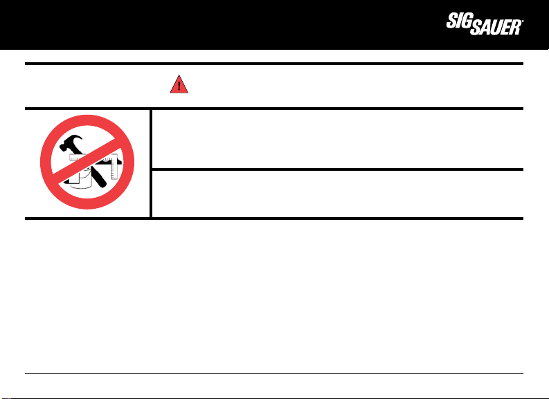
WARNING - ALTERATIONS
This product was designed to function properly in its original condition.
Alterations can make it unsafe. Do not alter any part or add or substitute any
parts or accessories not manufactured by SIG SAUER Inc.
DO NOT ALTER ANY GUN
™
www.sigsauer.com
13
Page 14

GENERAL SAFETY INFORMATION AND MECHANICAL CHARACTERISTICS
1.0 Safety Information
The safety warnings in this manual are important. By understanding the dangers inherent in the use of any firearm, and
by taking the precautions described herein, you can enjoy complete safety in the use of your rifle. Failure to heed any of
these warnings may result in serious injury to you or others, as well as severe damage to the firearm or other property.
SIG SAUER Inc. shall not be responsible in any manner whatsoever for malfunctioning of the firearm, physical injury or
property damage resulting in
whole or in part from:
1) criminal or negligent discharge;
2) improper or careless handling;
3) unauthorized modifications;
4) defective, improper, hand-loaded, or reloaded ammunition;
5) corrosion;
6) neglect; or
7) other influences beyond our direct and immediate control.
This limitation applies regardless of whether liability is asserted on the basis of contract, negligence, or strict liability
(including any failure to warn). Under no circumstance shall SIG SAUER Inc. be liable for incidental or consequential
damages, such as loss of use of property, commercial loss, and loss of earnings or profits.
14
www.sigsauer.com
Page 15

when it counts
THE BASIC RULES OF SAFE FIREARMS HANDLING
1. ALWAYS treat every gun as if it were loaded.
2. ALWAYS be sure the barrel is clear of any obstruction.
3. ALWAYS be sure of your backstop, what lies beyond, and the safety of bystanders before you shoot.
4. ALWAYS use clean, dry, original factory-made ammunition of the proper type and caliber for your gun.
5. ALWAYS wear ear protection and safety glasses when shooting.
6. ALWAYS carry your gun so that you can control the direction of the muzzle if you fall or stumble.
7. NEVER shoot at a flat surface or water.
8. DO NOT leave an unattended gun loaded. Guns and ammunition should be stored separately, locked if possible, beyond
the reach of children, careless adults, and unauthorized users.
9. NEVER allow your firearm to be used by anyone who has not read and understood this operator’s manual.
10. DO NOT point any gun, loaded or unloaded, at any undesired target.
11. NEVER fire your rifle near an animal unless it is trained to accept the noise: an animal’s startled reaction could injure it
or cause an accident.
12. NEVER drink alcoholic beverages or take drugs before or during shooting, as your vision and judgment could be
seriously impaired, making your gun handling unsafe.
™
www.sigsauer.com
15
Page 16

1.1 Protect Your Eyes And Ears
Always wear safety glasses and ear plugs or “earmuff” type protectors whenever you are shooting. Always make certain
that persons close to you are similarly protected. Unprotected eyes may be injured by powder, gas, carbon residue,
lubricant, metallic particles, or similar debris which may emanate occasionally from any firearm in normal use. Without
ear protection, repeated exposure to shooting
noise may lead to cumulative, permanent hearing loss.
1.2. Ammunition
1. Use only high quality, original, factory-manufactured ammunition. Do not use cartridges that are dirty, wet, corroded,
bent, or damaged. Do not oil cartridges. Do not spray aerosol-type lubricants, preservative, or cleaners directly onto
cartridges or where excess spray may flow into contact with cartridges. Lubricant or other foreign matter on cartridges
can cause potentially dangerous ammunition malfunctions. Use only ammunition of the caliber for which your firearm is
chambered. The proper caliber is permanently engraved on your firearm; never attempt to use ammunition of any other
caliber.
2. The use of reloaded, “remanufactured” hand-loaded, or other non-standard ammunition voids all warranties. Reloading
is a science and improperly loaded ammunition can be extremely dangerous. Severe damage to the firearm and serious
injury to the shooter or to others may result. Always use ammunition that complies with the industry performance
standards established by the Sporting Arms and Ammunition Manufacturers’ Institute, Inc. of the United States (SAAMI) or
ammunition manufactured to military specifications.
16
www.sigsauer.com
Page 17

WARNING – AMMUNITION (CARTRIDGE) NOTICE
when it counts
™
INJURY WHATSOEVER OCCURRING IN CONNECTION WITH, OR AS A RESULT OF, THE USE IN ANY SIG SAUER FIREARM OF
SIG SAUER Inc. SPECIFICALLY DISCLAIMS RESPONSIBILITY FOR ANY DAMAGE OR
FAULTY, NON-STANDARD, “REMANUFACTURED” HAND LOADED (RELOADED) AMMUNITION, OR CARTRIDGES OTHER THAN
THOSE FOR WHICH THE FIREARM WAS ORIGINALLY CHAMBERED.
3. Firearms may be severely damaged and serious injury to the shooter or to others may result from any condition
causing excessive pressure inside the chamber or barrel during firing. Excessive pressure can be caused by obstructions
in the barrel, propellant powder overloads, the use of incorrect cartridges or defectively assembled cartridges. In addition,
the use of a dirty, corroded, or damaged cartridge can lead to a burst cartridge case and consequent damage to the
firearm and personal injury from the sudden escape of high-pressure propellant gas within the firearm’s mechanism.
4. Immediately stop shooting and check the barrel for a possible obstruction whenever:
• You have difficulty in, or feel unusual resistance in, chambering a cartridge;
• A cartridge misfires (does not go off);
• The mechanism fails to extract a fired cartridge case;
• Unburned grains of propellant powder are discovered spilled in the mechanism;
• A shot sounds weak or abnormal. In such cases it is possible that a bullet is lodged part way down the barrel.
• Firing a subsequent bullet into the obstructed barrel can wreck the firearm and cause serious injury to the shooter
or to bystanders.
www.sigsauer.com
17
Page 18

5. Bullets can become lodged in the barrel:
• If the cartridge has been improperly loaded without propellant powder, or if the powder fails to ignite (ignition of
the cartridge primer alone will push the bullet out of the cartridge case, but usually does not generate sufficient
energy to expel the bullet completely from the barrel);
• If the bullet is not properly seated in the cartridge case. When such a cartridge is extracted from the chamber
without being fired, the bullet may be left behind in the bore at the point where the rifling begins. Subsequent
chambering of another cartridge may push the first bullet further into the bore.
6. If there is any reason to suspect that a bullet is obstructing the barrel, immediately unload the firearm and look through
the bore. It is not sufficient to merely look in the chamber. A bullet may be lodged some distance down the barrel where
it cannot easily be seen.
IF A BULLET IS IN THE BORE, DO NOT ATTEMPT TO SHOOT IT OUT BY USING ANOTHER CARTRIDGE OR BY
BLOWING IT OUT WITH A BLANK OR ONE FROM WHICH THE BULLET HAS BEEN REMOVED. SUCH TECHNIQUES CAN
GENERATE EXCESSIVE PRESSURE, WRECK THE FIREARM, AND CAUSE SERIOUS PERSONAL INJURY.
If the bullet can be removed with a cleaning rod, clean any unburned powder grains from the bore, chamber, and
mechanism before resuming shooting. If the bullet cannot be dislodged by tapping it with a cleaning rod, take the firearm
to a gunsmith.
7. Dirt, corrosion, or other foreign matter on a cartridge can impede complete chambering and may cause the cartridge
case to burst upon firing. The same is true of cartridges which are damaged or deformed.
18
www.sigsauer.com
Page 19

when it counts
8. Do not oil cartridges, and be sure to wipe the chamber clean of any oil or preservative before commencing to shoot. Oil
interferes with the friction between cartridge case and chamber wall that is necessary for safe functioning, and subjects
the firearm to stress similar to that imposed by excessive pressure.
9. Use lubricants sparingly on the moving parts of your firearm. Avoid excessive spraying of any aerosol gun care product,
especially where it may get on ammunition. All lubricants and aerosol spray lubricants in particular can penetrate
cartridge primers and cause misfires. Some highly penetrative lubricants can also migrate inside cartridge cases and
cause deterioration of the propellant powder; on firing, the powder may not ignite. If only the primer ignites, there is
danger that the bullet may become lodged in the barrel.
™
www.sigsauer.com
19
Page 20
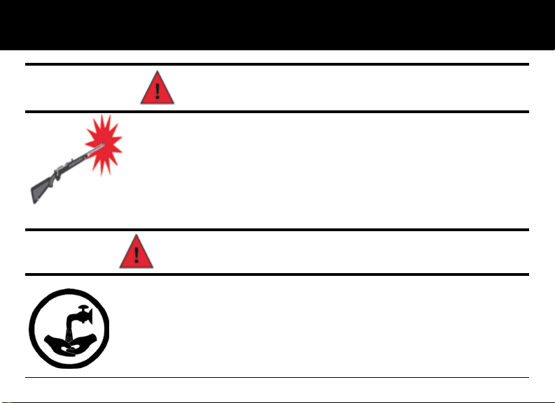
WARNING - AMMUNITION
Death, serious injury, and damage can result from the use of wrong ammunition, bore
obstructions, powder overloads, or incorrect cartridge components. Always wear shooting
glasses and hearing protectors.
IMPROPER AMMUNITION DESTROYS GUNS
WARNING - LEAD EXPOSURE
Discharging firearms in poorly ventilated areas, cleaning firearms, or handling ammunition may
result in exposure to lead and other substances known to the state of California to cause birth
defects, reproductive harm, and other serious physical injury. Maintain adequate ventilation at
all times. Wash hands thoroughly after exposure.
SHOOTING OR CLEANING GUNS MAY EXPOSE YOU TO LEAD
20
www.sigsauer.com
Page 21
when it counts
2.0. Mechanical Characteristics and Rifle Theory
2.1 Rifle Description
2.1.1 General
The SIG716 rifle is a gas operated short stroke pushrod rifle with a rotary bolt mechanism capable of semi-automatic or
full automatic fire depending on the model. Semi-Automatic is defined as one round being fired each time the trigger is
pressed to the rear. Full automatic or select fire is defined as a continuous rate of fire beginning with the initial press
of the trigger and continuing until either the magazine is depleted of ammunition or the operator releases the trigger, at
which time the trigger resets. The rifle is chambered in 7.62x51mm NATO and is compatible with .308 Winchester ammunition.
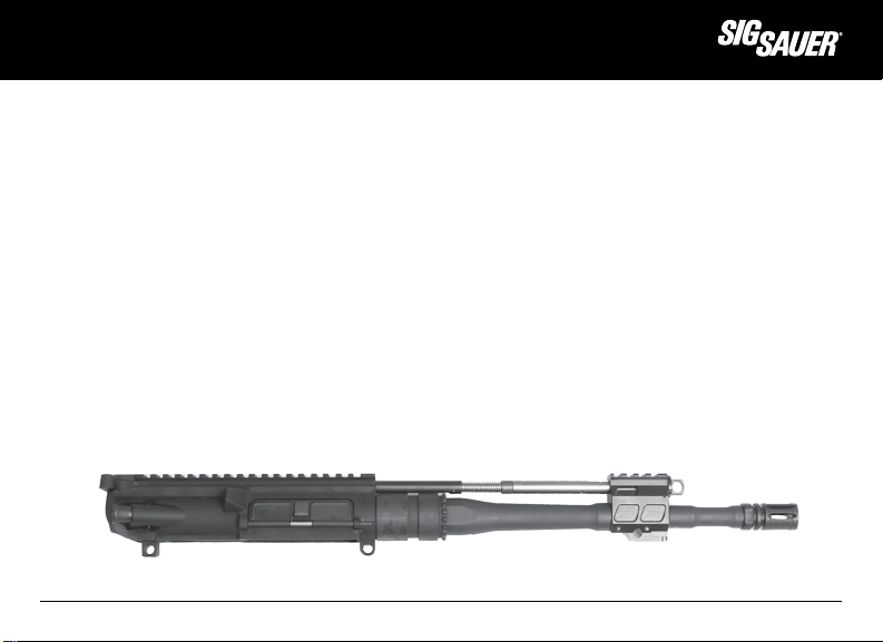
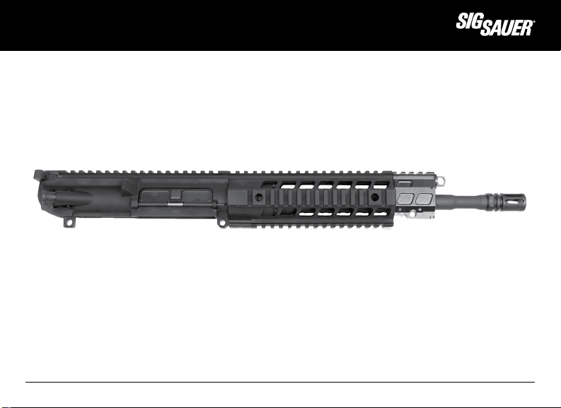
2.1.2 Barrel, Receiver and Gas System
The barrel is mechanically mated to the receiver by means of a barrel nut, and the barrel extension. The flash suppressor
if applicable is screwed onto the muzzle end of the barrel via 5/8 x 24 TPI thread pattern. The gas block, which is fitted to
the barrel, contains the gas port and the gas valve which locates the pushrod to the upper receiver. The upper receiver
has an integral M1913 accessory rail for attachment of sights or optics.
FIG 1 BARREL WITH RECEIVER AND GAS SYSTEM
www.sigsauer.com
™
21
Page 22
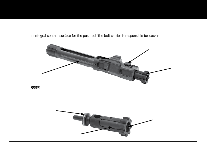
2.1.3 Bolt/Bolt Carrier Assembly
The bolt carrier guides the bolt and controls locking and unlocking by means of the cam pin. The bolt carrier also
incorporates an integral contact surface for the pushrod. The bolt carrier is responsible for cocking the hammer.
Cam Pin
Bolt
Bolt Carrier
FIG 2 BOLT CARRIER
The bolt houses the firing pin, the extractor and the ejector. It incorporates locking lugs that lock the bolt into the barrel
extension. The cam pin passes into the bolt which allows for locking and unlocking and is retained in the bolt by the firing pin.
Bolt Rings
Ejector
FIG 3 BOLT ASSEMBLY
22
Extractor
www.sigsauer.com
Page 23
when it counts
2.1.4 Quad Rail Hand Guard
The quad rail hand guard protects the barrel and the gas system from damage and provides protection from barrel heat.
The integrated M1913 accessory rails provide attachment points for various devices , such as lights, lasers, sights, and
bi-pods. The quad rail hand guard has unique attachment features that enhances the rifle overall structural integrity.
FIG 4 QUAD RAIL ASSEMBLY ON RIFLE
™
www.sigsauer.com
23
Page 24

2.1.5 Lower Receiver Assembly and Butt stock
The lower receiver assembly contains the fire control mechanism, bolt catch, magazine well, magazine release, pistol
grip, sling attachment points, and butt stock assembly. The fire control selector is ambidextrous along with the magazine
catch. The fire control selector has two positions, SAFE-SEMI.
SAFE - Trigger is locked and rifle cannot be fired.
SEMI - The rifle will fire one shot with each press of the trigger.
Magazine release
Sling attachment point
FIG 5 LOWER RECEIVER ASSEMBLY
24
www.sigsauer.com
Page 25
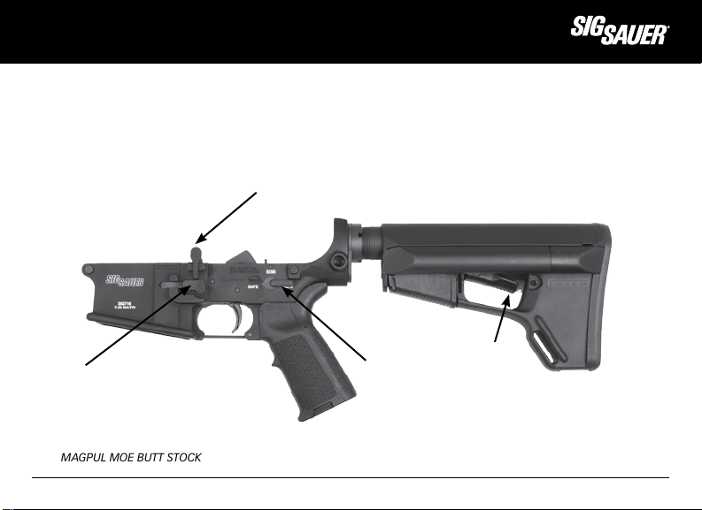
The SIG716 is equipped with a telescoping butt stock. The butt stock may vary depending on the model.
Bolt Catch Lever
Release Latch
Magazine release
Fire control selector
FIG 6 MAGPUL MOE BUTT STOCK
when it counts
™
www.sigsauer.com
25
Page 26
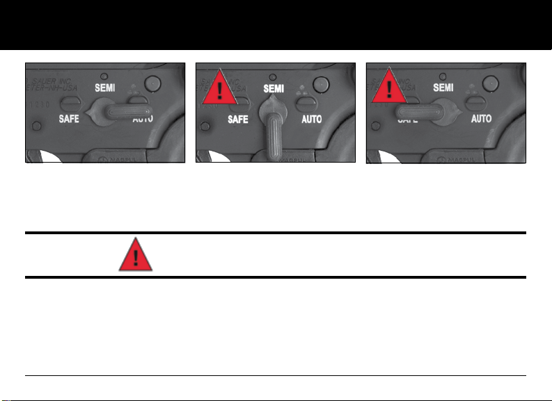
MANUAL SAFETY “ON”
FIG 7 FIRE CONTROL SELECTOR POSITION SAFE-SEMI-AUTO
MANUAL SAFETY “OFF”
MANUAL SAFETY “OFF”
WARNING - MANUAL SAFETY:
Keep the safety “ON” unless actually firing. Always move the safety to its intended position and check it. The safety is
not “ON” unless it is completely “ON.” Never depend on a safety mechanism or any other mechanical device to justify
careless handling or permitting the rifle to point in an unsafe direction. The only “safe” rifle is one in which the bolt is
open, the chamber is empty, and there is no magazine in the gun.
KNOW HOW TO USE THE SAFETY
26
www.sigsauer.com
Page 27
when it counts
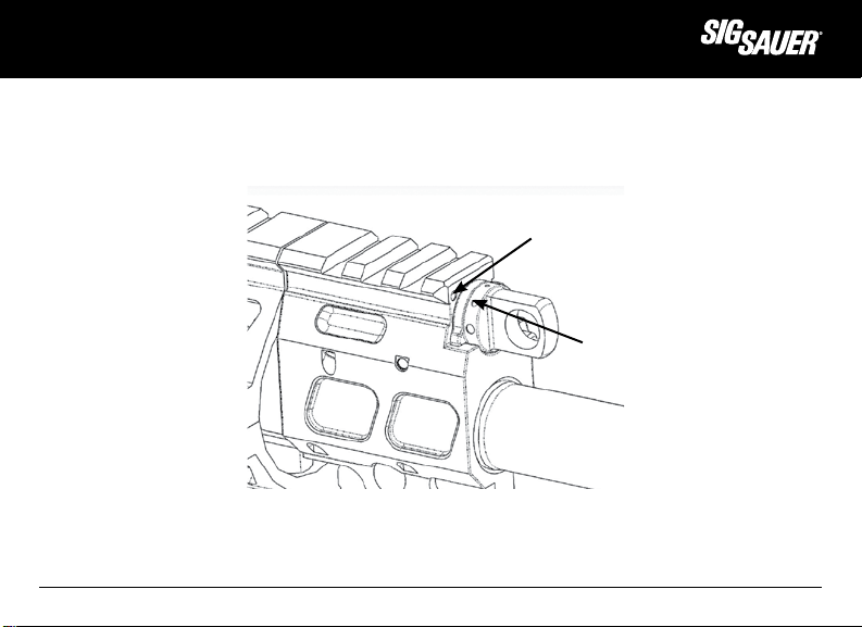
2.1.6 Gas Valve Position
The SIG716 gas valve has 4 positions. Rotating the valve between “Normal “ and “Adverse” can be accomplished by
just rotating the valve clockwise to the next position. Rotation to “Suppressed” or “Off” positions will require the detent
plunger to be depressed prior to rotation of the valve.
Locator point on gas block
Position indicator point on gas valve
FIG 8 ADJUSTABLE GAS VALVE
™
www.sigsauer.com
27
Page 28
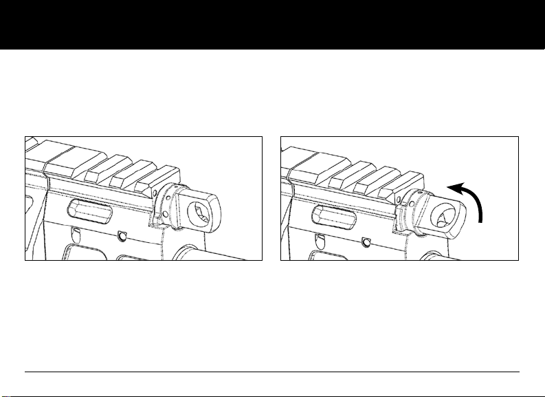
2.1.6.A Position #1
(Normal) is for normal operation.
2.1.6.B Position #2
(Adverse) is for adverse conditions such as fouling or
under functioning.
FIG 9 GAS VALVE ON P1
CAUTION: The rifle should NOT be operated in Position #2 (Adverse) for an extended period of time. As soon as normal
function returns, the gas valve should be rotated to Position #1 (Normal). Continued operation with the gas valve in
Position #2 (Adverse) will increase recoil and place unnecessary stress on the rifle. Having to operate the rifle in Position
#2 (Adverse) is an indicator that the rifle needs maintenance.
28
www.sigsauer.com
FIG 10 GAS VALVE ON P2 ADVERSE
Page 29
when it counts
™
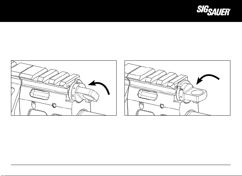
2.1.6.C Position #3
(Suppressed) is for firing with a sound suppressor and is a
partial cutoff of the gas system still allowing for cycling of
the weapon. You must depress the valve plunger prior to
rotating the gas valve to this position.
FIG 11 GAS VALVE ON SUPPRESSED MODE
(ACTION WILL CYCLE)
When the cycle of operation is affected by fouling or environmental conditions, the gas valve can be rotated to the
Position 2 detent. In this position, a larger volume of gas is released against the pushrod. The need to utilize this position
is an indication that the rifle requires cleaning.
2.1.6.D Position #4
(Off) is a complete cutoff of the gas system allowing the
rifle to function as a single shot weapon.
FIG 12 GAS VALVE ON P4 POSITION, SUPPRESSED MODE
(THE ACTION WILL NOT CYCLE)
www.sigsauer.com
29
Page 30

2.1.7 Butt Stock Operation
The butt stock on the SIG716 may vary depending on the specific model you have. The butt stock provides for easy
adjustment of the length to accommodate the individual shooter or for storage. To adjust the length of the butt stock,
fully depress the release latch and pull the stock rearward to extend or push the stock forward to collapse.
Intermediate positions may be selected by partially depressing the release latch and moving the stock to the desired
position.
FIG 13 BUTT STOCK COLLAPSED AND FULLY EXTENDED
Release Latch
To remove the butt stock:
Depress the adjustment lever to disengage the release latch and slide the stock to full extension.
Grasp both ends of the release pin and pull down as you slide the stock from the receiver extension.
30
www.sigsauer.com
Page 31

when it counts
With the release lever fully depressed, insert the tip of the included Polymer Dummy Round into the recessed hole in the
locking pin. Use the Polymer Dummy Round as a lever to pry the locking pin down to its stopping point. Once the locking
pin is clear of the receiver extension you can slide the stock off of the receiver extension.
FIG 14 BUTT STOCK REMOVAL
www.sigsauer.com
™
31
Page 32

To re-install the butt stock:
DO NOT FORCE THE PARTS TOGETHER! Align the stock body with the receiver extension and gently slide the stock on to
the extension until it stops. With the release lever fully depressed, insert the tip of the included Polymer Dummy Round
into the recessed hole in the locking pin. Use the Polymer Dummy Round as a lever to pry the locking pin down to its
stopping point. Once the locking pin is clear of the receiver extension you can slide the stock onto the receiver extension.
Check to see that the stock moves to all positions locks into place.
FIG 15 INSERT VIEW OF BUTT STOCK INSTALLATION
32
www.sigsauer.com
Page 33

when it counts
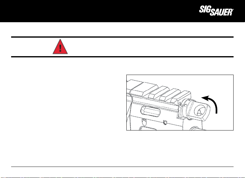
2.1.8 Trigger Guard Operation
The trigger guard may be released from its normal position to make the trigger accessible for shooting with gloves. For
safety reasons the trigger guard must not be released until just before firing the weapon. It should be returned to its
normal position immediately.
CAUTION: BE CAREFUL WHEN INSERTING GLOVED FINGERS INTO THE TRIGGER GUARD AS ACCIDENTAL DISCHARGES MAY
OCCUR!
To release the trigger guard, depress the spring loaded detent on the front right side and rotate the guard downward.
FIG 16 TRIGGER AND GUARD RELEASE
To close the guard rotate the trigger guard back into place, depress the spring loaded detent and ensure the guard locks
into place.
www.sigsauer.com
™
33
Page 34

WARNING:
DO NOT MANIPULATE THE TRIGGER GUARD UNLESS THE FIRE CONTROL SELECTOR
IS ON “SAFE” AND THE RIFLE IS UNLOADED.
34
www.sigsauer.com
Page 35

when it counts
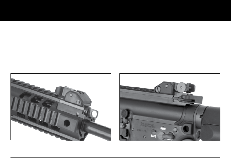
2.1.9 Sights
The SIG716 rifle features integrated Mil-Std M1913 rails on the upper receiver and the Quad Rail Hand Guards. These
rails may be used for attaching a variety of sighting systems, both optical and fixed. Some models feature SIG SAUER flip
up front and rear sights as a standard feature. These sights are designed to provide a simple, durable sighting solution
should you decide not to use an optical device. Markings on all rail surfaces give you a reference point to reattach your
sighting system in exactly the same place should you need to remove it for service.
FIG 17 FRONT AND REAR SIGHTS
™
www.sigsauer.com
35
Page 36
Sight Deployment
Flip up the front sight assembly until it held in the upright position by the detent.
Flip up the rear sight assembly until it is held in the upright position by the detent.
When the sights are not longer required, rotate them down to their stowed position.
Windage Adjustment (Left/Right)
FRONT SIGHT REAR SIGHT
36
www.sigsauer.com
Page 37

CHANGES IN POINT OF IMPACT ON A 25M TARGET (16.0” bbl)
ELEVATION WINDAGE
1 CLICK
2 CLICKS
3 CLICKS
4 CLICKS
1.1 cm
2.2 cm
3.4 cm
4.5 cm
1 CLICK
2 CLICKS
3 CLICKS
4 CLICKS
To move your shot group UP rotate the front sight post clockwise
To move your shot group DOWN rotate the front sight post counter clockwise
To move your shot group to the LEFT rotate the windage screw counter clockwise
To move your shot group to the RIGHT rotate the windage screw clockwise
0.4 cm
0.9 cm
1.3 cm
1.8 cm
when it counts
™
www.sigsauer.com
37
Page 38
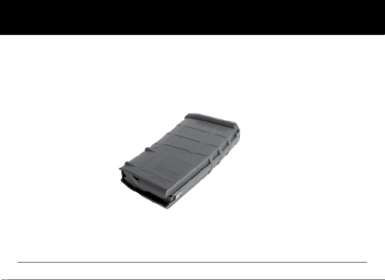
2.1.10 Magazine
The SIG716 rifle ships with (1) one twenty (20) round polymer magpul magazine. The SIG716 is compatible with SR25
AR10 type magazines.
Aftermarket magazines should always be checked for proper fit and function prior to using them with the SIG716 rifle.
FIG 20, 20 RD MAGAZINE
38
www.sigsauer.com
Page 39

when it counts
2.2 Technical Specifications
SPECIFICATION CQB PATROL PRECISION MARKSMAN
Caliber 7.62x51mm NATO 7.62x51mm NATO 7.62x51mm NATO
Overall Length 34.25” 37.4” 39.4”
Length w/stock collapsed 31.1” 34.25 N/A
Overall Height 7.6” 7.6” 7.6”
Barrel Length w/o Flash Suppressor 12.5” 16.0” 20.0”
Barrel Contour Short Med Weight Std Med weight Heavy Match
Twist Rate/Grooves 1:10/6 Groove RH 1:10/6 Groove RH 1:10/6 Groove RH
Muzzle Device Flash Suppressor Flash Suppressor Threaded w/ Cap
Sight Radius 15.5” 15.5” 21.25”
Weight w/o Magazine 8.36 lbs 9.2 lbs 10.56 lbs
Magazine (Ships with) 20 Rd Magpul P Mag 20 Rd Magpul P Mag 20 Rd Magpul P Mag
Trigger Mil-Spec Mil-Spec 2 Stage Match
Trigger Weight 7.6 lbs 7.6 lbs 5.4 lbs
Cyclic Rate(Select Fire Models) 650-720 RPM 650-720 RPM Semi-Auto Only
™
www.sigsauer.com
39
Page 40
2.2.1 Operation of Fire Control/Safety
Four basic fundamentals of safe firearm handling should be applied during any and all activities described in this manual.
Treat every firearm as if it were loaded.
Always keep the muzzle pointed in a safe direction until ready to shoot.
Keep your finger off of the trigger and out of the trigger guard until ready to fire.
Be aware of your target and what is beyond it.
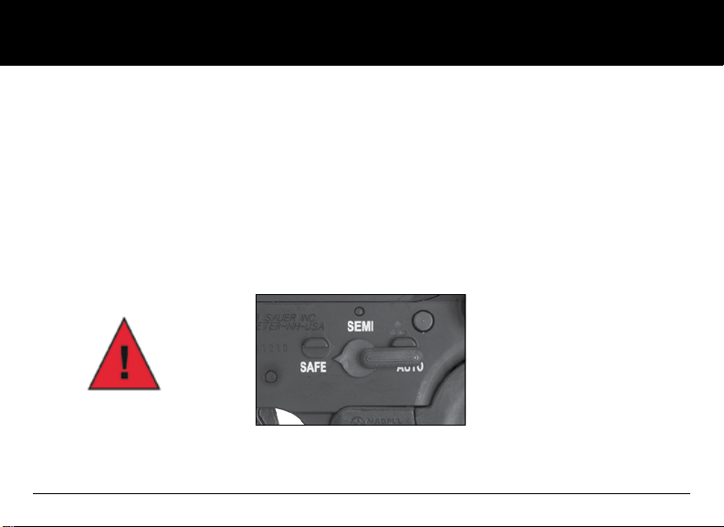
The SIG716 is equipped with an ambidextrous fire control selector lever commonly referred to as a “safety lever” which can
be manipulated from either the left or right side of the lower receiver. The selector has two (2) positions, SAFE and SEMI.
SAFE - Trigger is locked and rifle CANNOT be fired with a normal press of the trigger.
MANUAL SAFETY “ON”
FIG 21 FIRE CONTROL SELECTOR ON SAFE
40
www.sigsauer.com
Page 41

when it counts
SEMI – The trigger is no longer locked and the rifle WILL FIRE one shot with each press of the trigger until either the
operator stops firing or the ammunition is expended from the magazine.
™
MANUAL SAFETY “OFF”
MANUAL SAFETY “OFF”
FIG 22 FIRE CONTROL SELECTOR ON SEMI-AUTO
The fire control selector should always be in the SAFE position except when the operator is actually going to fire the rifle,
and upon completion of firing.
www.sigsauer.com
41
Page 42

3.0 Handling
3.1 Important Instructions
• Before manipulating the weapon, ensure the fire control lever is in the “S” (SAFE) position and the trigger guard is in
the closed position.
• Use only factory-new ammunition which corresponds to the caliber of the weapon.
• During all manipulations of the rifle, point the weapon in a safe direction.
• Do not place your finger on the trigger until the target has been verified and you intend to shoot.
• Do not load the weapon until immediately before use.
• Unload weapon immediately after shooting is finished.
• Remove the bolt carrier assembly and magazine from the weapon prior to transportation.
WARNING - HANDLING:
Never carry the rifle loaded with the safety lever in the “F” (FIRE) position. If dropped or struck with the safety off (“F”),
the rifle may fire. Such a discharge can occur with or without the trigger being directly struck or touched. Never rest a
loaded rifle against any object (wall, tree, fence, vehicle, etc.) because there is always the possibility that the rifle will
be jarred or slide from its position and fall with sufficient force to discharge. Keep the safety lever on “S” (SAFE) unless
actually firing.
ANY GUN MAY FIRE IF DROPPED
42
www.sigsauer.com
Page 43

when it counts
3.2 Loading the Magazine
FIG 23 716 MAGAZINE BEING LOADED
1. Ensure the magazine is the proper type and caliber for the rifle;
2. Place a round between the feed lips and press down- ensure the bullet is facing the front of the magazine;
3. Ensure the cartridges are fully seated to the rear of the magazine by tapping the back of the magazine in the palm of
the hand.
™
www.sigsauer.com
43
Page 44

3.3 Loading the Rifle
1. Ensure the safety lever is in the “S” (SAFE) position;
2. Insert the magazine and check that it is properly seated;
3. Bolt forward: Pull the charging handle back fully and release; or
4. Bolt locked open: Depress bolt catch fully to release bolt.
WARNING:
DO NOT LOAD A RIFLE WITH A HOT CHAMBER BECAUSE A ROUND
MAY “COOK” OFF (i.e., a round may detonate (fire) unexpectedly
just because it is exposed to the heat of the rifle’s chamber).
FIG 24 MAGAZINE BEING INSERTED
44
www.sigsauer.com
Page 45

3.4 Reloading the Rifle after firing has commenced (partially loaded
magazine still in rifle).
1. Place fire control selector on SAFE.
2. Keep muzzle pointed in a safe direction and finger out of the trigger guard!
3. Depress magazine catch and remove magazine.
FIG 25 MAG CATCH BEING DEPRESSED LEFT AND RIGHT SIDE
4. Insert loaded magazine and ensure it is seated properly.
when it counts
™
www.sigsauer.com
45
Page 46

3.5 Reloading the Rifle after firing has commenced (bolt locked open, empty
magazine still in rifle).
1. Place fire control selector on SAFE.
2. Keep muzzle pointed in a safe direction and finger out of the trigger guard!
3. Depress magazine catch and remove magazine.
4. Insert loaded magazine and ensure it is seated properly.
5. Release the bolt by either:
a. Depressing bolt catch fully releasing the bolt;
b. Grasping the charging handle, retracting it slightly and releasing it.
WHEN COMPLETING STEP 5.B ABOVE, RELEASE THE CHARGING HANDLE AND LET IT GO FORWARD UNDER FULL SPRING
POWER. DO NOT RIDE THE CHARGING HANDLE FORWARD AS THIS MIGHT CAUSE A FAILURE OF THE CARTRIDGE TO FULLY
SEAT INTO BATTERY.
46
www.sigsauer.com
Page 47

when it counts
4.0 Cycle of Operation
Ready to Fire Condition
The SIG716 “Ready to Fire” condition is described as a loaded magazine properly seated into the magazine well, a live
cartridge loaded into the chamber, the fire control selector place on “SAFE”.
WARNING - FIRING
The bolt automatically opens and shuts quickly while firing. Keep face and
hands away from it. Hot brass and powder gas is ejected quickly and can
burn you. The rifle should be fired from the right shoulder. Always wear
shooting glasses and hearing protectors.
BOLT OPENS FAST – HOT BRASS EJECTED
™
www.sigsauer.com
47
Page 48

4.1 Firing
Semi-Auto Models (SAFE-SEMI)
Rotate the fire control selector from the “SAFE” position to the “SEMI” position.
Pressing the trigger rearward releases the hammer causing it to strike the firing pin, impacting the cartridge primer.
Select Fire Models (SAFE-SEMI-AUTO)
Rotating the fire control selector from “SAFE” to “AUTO” or “SEMI” to “AUTO” will produce a continuous rate of fire beginning with the initial press of the trigger and continuing until either the magazine is depleted of ammunition or the operator
releases the trigger, at which time the trigger resets. On “AUTO” releasing the trigger allows the hammer to be captured by
the trigger sear and not the disconnect as it would be when in “SEMI-AUTO” mode. Pressing the trigger again will produce a
continuous rate of fire until either the magazine is depleted of ammunition or the operator releases the trigger.
CAUTION: THE SIG716 IS A SEMI-AUTOMATIC RIFLE AND WILL AUTOMATICALLY RELOAD THE NEXT CARTRIDGE IN THE
MAGAZINE AFTER THE CHAMBERED CARTRIDGE IS FIRED FOLLOWING ONE PRESS OF THE TRIGGER. THE RIFLE WILL NOW
BE READY TO FIRE AGAIN ONCE THE TRIGGER IS RELEASED.
4.1.1 Unlocking of Bolt; Extraction & Ejection
1. The gas pressure generated by the burning powder in the cartridge, propels the bullet through the bore of the barrel.
2. When the bullet passes the gas port in the barrel a portion of the gas flows up into the gas block and into the gas valve.
3. The gas travels through the port in the adjustable gas valve and drives the pushrod rearward.
4. The pushrod then pushes the bolt carrier assembly to the rear.
5. As the bolt carrier moves rearward the cam pin allows the bolt to rotate to the right and unlock from the barrel
extension.
48
www.sigsauer.com
Page 49

when it counts
6. As the bolt carrier continues rearward movement the extractor, gripping the right side of the expended cartridge case
pulls the case from the chamber.
7. Once the expended case clears the chamber, the ejector located on the left side of the bolt face pushes the case out
the ejection port located on the right side of the upper receiver.
4.1.2 Cocking of the Hammer
1. As the bolt carrier assembly continues rearward the bottom surface of the bolt carrier cocks the hammer rearward.
2. The hammer is then captured by the disconnect and held in place.
4.1.3 Chambering and Locking
1. Once the bolt carrier reaches its full rearward travel the buffer and recoil spring force the bolt carrier assembly forward.
2. As the bolt carrier assembly moves forward the next cartridge is stripped from the magazine and loaded into the chamber.
3. The bolt continues forward, rotates to the left, and locks into place.
4. The trigger is released and the hammer moves to its location of engagement with the trigger.
5. The rifle is now ready to be fired again.
™
www.sigsauer.com
49
Page 50

5.0 Unloading
ALWAYS MAKE SURE THE MUZZLE IS POINTED IN A SAFE DIRECTION!
1. Ensure the fire control selector is rotated to the “SAFE” position.
2. Remove the magazine by depressing the magazine catch; and
3. Retract the charging handle locking the bolt carrier assembly to the rear; and
4. Visually and physically inspect the chamber to verify it is empty.
Remember to clear the chamber after the magazine is removed.
Never assume that any firearm is unloaded until you have personally checked it, visually and physically.
After every range session make sure the firearm is unloaded before you leave the range.
WARNING:
Removing cartridges from the magazine does not prevent the rifle from being fired! When there is a cartridge in the
chamber and the safety lever is in the “F” (FIRE) position, the cartridge will discharge if the trigger is pulled. It is absolutely
essential for the user to know how to completely unload the rifle.
“Completely” means emptying the magazine and removing a chambered cartridge. The safety lever should always be in
the “S” (SAFE) position when the rifle is being unloaded.
THE RIFLE WILL FIRE EVEN IF THE MAGAZINE IS EMPTY OR REMOVED
50
www.sigsauer.com
Page 51

when it counts
TO CLEAR A STOPPAGE (JAM)
6.0 Procedures In Case of a Stoppage
A “Stoppage” is an interruption in the cycle of operation as depicted in Section 4.0. A stoppage can normally be repaired
by the operator by performing one of the following immediate actions described.
6.1 Failure to Fire (Cold Rifle) Trigger is pressed, hammer falls, rifle does not fire.
1. Ensure the magazine is properly seated in the magazine well by applying upward pressure and then pulling down on
the magazine.
2. Retract the charging handle all the way back and observe the ejection of the expended case or a live cartridge; and
3. Visually inspect the chamber for any obstructions, if the chamber shows to be clear, release the charging handle to
feed a new cartridge. Do NOT ride the charging handle forward.
4. Attempt to fire the rifle again.
™
www.sigsauer.com
51
Page 52

6.2 Failure to Fire (Hot Rifle) Trigger is pressed, hammer falls, the rifle does
not fire.
1. Keep the muzzle pointed down range, place the rifle on SAFE, remove the magazine, if you cannot extract the loaded
cartridge within ten (10) seconds you must wait a minimum of 15 minutes before handling the rifle.
2. Upon completion of the 15 minutes, retract the charging handle all the way back and observe the ejection of the
cartridge; and
3. Visually inspect the chamber for any obstructions, if the chamber shows to be clear, release the charging handle to
feed a new cartridge. DO NOT ride the charging handle forward.
4. Attempt to fire the rifle again.
If the rifle does not fire after completing 6.1 or 6.2:
1. Unload, and clear the rifle. 3. Cycle the bolt assembly chambering a round; and
2. Insert a fresh magazine; 4. Attempt to fire the rifle.
If the rifle fails to fire after attempting all of the above, the rifle should be returned to SIG SAUER, Inc. for evaluation by a
factory trained technician.
WARNING:
EXCESSIVE HEAT BUILD UP IN THE CHAMBER CAN CAUSE WHAT IS REFERRED TO AS A “COOK OFF”. THIS MEANS THE
HEAT IN THE CHAMBER CAUSES THE POWDER TO IGNITE IN THE CHAMBERED CARTRIDGE. THE ROUND THEN DETONATES
JUST AS IF IT WERE FIRED. IF THE RIFLE HAS BEEN FIRED FOR AN EXTENDED PERIOD OF TIME FOLLOW THE STEPS IN 6.2.
52
www.sigsauer.com
Page 53
when it counts
6.3 Failure to Cycle
WARNING:
Always ensure the rifle is unloaded and cleared of ammunition prior to adjusting the gas valve as described below.
If the SIG716 fires one round but fails to cycle the action:
1. Place the fire control selector to “SAFE”
2. Remove the magazine; and
3. Lock the bolt carrier to the rear;
4. Ensure the chamber is clear (visual and physical check);
5. Rotate the gas valve from Position #1 (Normal) to
Position # 2 (Adverse);
6. Reinsert a fresh magazine;
7. Release the bolt forward; and
8. Rotate the fire control selector to “SEMI” and attempt
to fire the rifle.
FIG 26 GAS VALVE ROTATED TO POSITION 2
™
www.sigsauer.com
53
Page 54

6.4 Feedway Stoppage (Jam)
A feedway stoppage occurs when one or more rounds are trapped in the upper receiver and stop the cycle of operation.
To clear this problem:
1. Place the rifle on SAFE.
2. Remove the magazine (You might have to pull downward with some force to remove the magazine from the magazine
well due to the jammed cartridges).
3. Cycle the bolt carrier assembly several times to clear any rounds from the receiver; and
4. Lock the bolt carrier to the rear, conduct a visual and physical inspection of the chamber to make sure the chamber
has no obstructions; and
5. Insert a fresh magazine and continue to fire the rifle.
CAUTION: Always remove the source of ammunition (magazine) prior to attempting to clear a stoppage that requires
retracting the charging handle/bolt carrier assembly as unintentional release of the spring loaded bolt carrier assembly
could detonate live cartridges lodged in the upper receiver.
54
www.sigsauer.com
Page 55

when it counts
7.0 Field Strip Disassembly
1. Unload and clear the rifle per section 5.0.
2. Ensure the bolt carrier assembly is forward and the fire control selector is placed on SAFE.
3. Press the takedown pin from left to right until it stops (It is held into the lower receiver by a detent and will not pull free
from the receiver).
Takedown Pin
Pivot Pin
FIG 27 THE TAKEDOWN PIN AND PIVOT PIN
™
www.sigsauer.com
55
Page 56
4. Press the Pivot Pin (front pin) from left to right until it stops at the detent.
5. Separate the upper receiver from the lower receiver.
6. Grasp the charging handle and pull it rearward until it stops.
7. Remove the bolt carrier assembly from the rear opening of the upper receiver.
8. Align the tabs of the charging handle and lift it from the receiver.
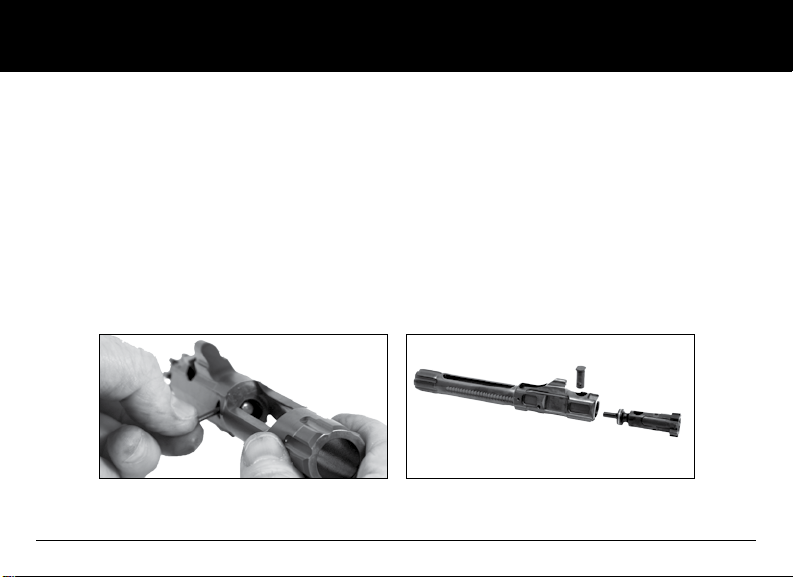
7.1 Detailed Disassembly of the Bolt Carrier and Bolt
1. Remove the firing pin retaining pin from the left side of the bolt carrier. A small punch might be needed for this
procedure.
2. Tilt the bolt carrier upward and catch the firing pin as it slides out of the rear of the bolt.
3. Rotate the bolt cam pin ¼ turn and lift it straight up out of the bolt carrier.
4. Pull the bolt out from the front of the bolt carrier.
FIG 28 INSERT DETAILED DIAGRAM OF BOLT AND BOLT CARRIER
56
www.sigsauer.com
Page 57
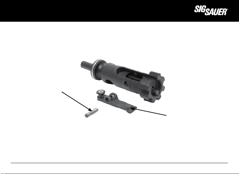
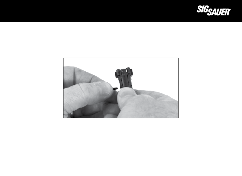
7.2 Extractor Removal
1. Apply slight pressure to the rear of the extractor with the thumb.
2. Using a punch, or the tip of the firing pin, push out the extractor pin. from either side.
3. Remove the extractor from the bolt.
Retaining Pin
Extractor
FIG 29 BOLT WITH EXTRACTOR REMOVED
NOTE: Only separate the extractor spring from the extractor when replacement is necessary
when it counts
™
www.sigsauer.com
57
Page 58

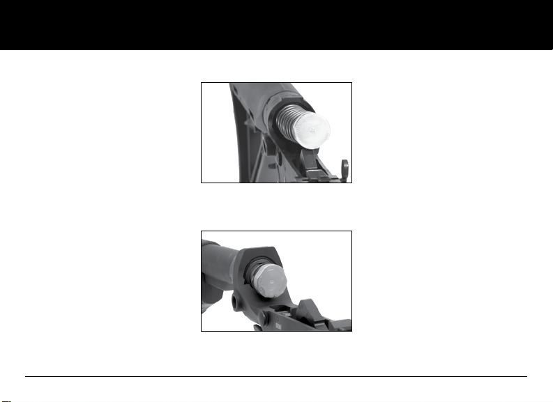
7.3 Gas Valve and Pushrod Removal
1. Depress the detent on the lower right side of the gas block.
2. Rotate gas valve clockwise until the lugs are clear of the gas block.
3. Pull the gas valve forward out of the gas block.
4. Tilt the upper downward and allow the push rod to slide from the gas block.
5. Separate the gas valve from the pushrod.
FIG 30 PICTURE OF THE
GAS VALVE BEING REMOVED
58
www.sigsauer.com
Page 59

when it counts
7.4 Quad Rail Removal
CAUTION: DO NOT REMOVE THE QUAD RAIL ASSEMBLY UNLESS THE UPPER AND LOWER RECEIVERS ARE SEPARATED.
REMOVAL OF THE QUAD RAILS WILL EXPOSE THE PUSHROD ASSEMBLY. SHOULD THE RIFLE FALL OR STRIKE A HARD
SURFACE, THE PUSHROD ASSEMBLY COULD BE DAMAGED EFFECTING OPERATION OF THE RIFLE. SEPARATING THE
RECEIVERS REDUCES THE OVERALL WEIGHT OF THE RIFLE REDUCING THE RISK OF DAMAGE SHOULD THE RIFLE FALL OR
STRIKE A HARD OBJECT OR SURFACE.
FIG 31 EXPLODED VIEW OF QUAD RAIL
™
www.sigsauer.com
59
Page 60

1. Remove the two (2) quad clamp screws using a 1/8” hex wrench.
FIG 32 REMOVAL OF CLAMP SCREWS AND CLAMP
2. Remove the four (4) handguard screws from the lower quad rail using a 5/32” hex wrench; and
FIG 33 REMOVAL OF 4 HANDGUARD SCREWS
60
www.sigsauer.com
Page 61

3. Remove the lower quad rail section.
FIG 34 REMOVAL OF THE LOWER RAIL SECTION
4. Lift the quad key from the slot in the barrel nut.
FIG 35 REMOVAL OF THE QUAD KEY FROM BARREL NUT
www.sigsauer.com
when it counts
™
61
Page 62

5. Remove the upper rail section.
FIG 36 REMOVAL OF UPPER RAIL SECTION
7.5 Removal of Recoil Buffer and Action Spring
REMOVAL OF THE RECOIL BUFFER AND SPRING IS EASIER IF THE HAMMER IS IN THE COCKED POSITION AND THE FIRE
CONTROL SELECTOR IS ROTATED TO THE SAFE POSITION. ALWAYS WEAR SAFETY GLASSES WHEN HANDLING PARTS
UNDER SPRING TENSION.
62
www.sigsauer.com
Page 63

when it counts
1. Depress buffer retaining plunger while maintaining control the buffer as you allow it to move forward from the receiver
extension tube.
FIG 37 PICTURE OF THUMB OVER BUFFER ASSEMBLY
2. Guide the buffer and action spring from the receiver extension.
3. Use a clockwise twisting motion to separate the action spring from the recoil buffer.
Do NOT pull straight back on the action spring as it can cause damage to the spring.
FIG 38 BUFFER AND RECOIL SPRING REMOVAL
www.sigsauer.com
™
63
Page 64

8.0 Cleaning
1. Your rifle is delivered factory packaged and preserved with a light coating of protective grease and oils. Before
loading make certain that all packing grease and oil has been cleaned from the bore and exposed mechanism.
2. Before you begin to disassemble your firearm for cleaning, always double-check to make sure it is unloaded!
3. After cleaning always check to be sure that no cleaning patch or other obstruction remains in the bore or chamber!
ONLY USE CLEANING AND LUBRICATION PRODUCTS THAT ARE SPECIFICALLY DESIGNED FOR USE ON FIREARMS.
DO NOT USE WIRE BRUSHES ON ALUMINUM SURFACES SUCH AS THE RECEIVERS OR QUAD RAILS AS THIS MAY SCRATCH
THE FINISH.
READ ALL WARNING LABELS AND OBTAIN MSDS ON ANY CLEANING, LUBRICATION, AND PROTECTIVE CHEMICALS USED.
CLEANER, LUBRICANT, PROTECTANT IS COMMONLY REFERRED TO AS “CLP”
SOME BORE CLEANERS ARE NOT MEANT TO BE LEFT IN THE BORE FOR EXTENDED PERIOD OF TIME.
FOLLOW ALL MANUFACTURER’S INSTRUCTIONS AND CAUTIONS WHEN USING CLEANING OR LUBRICATION PRODUCTS ON
FIREARMS.
SOLVENT IS A GENERIC TERM AND WILL BE USED TO DESCRIBE A GENERAL BORE CLEANING SOLUTION.
64
www.sigsauer.com
Page 65

when it counts
8.1 Cleaning the Bore
1. Run a patch soaked in solvent through the bore.
2. Allow the solvent to soak in the barrel for at least 5 minutes.
3. Move on to section 8.3 and clean the bolt while the solvent works on loosening the residue in the bore of the barrel.
4. If the barrel is heavily fouled use a cleaning rod and a brass or nylon bore brush of the proper bore diameter and clean
the bore from the chamber end to the muzzle end. Pass the brush completely out past the muzzle and do not change
direction in the bore as the brush can become stuck in the bore.
5. Run cotton patches through the bore until the patches come out clean. The bore and chamber of the barrel may be
lightly lubricated with an oily patch if the rifle is to be stored. Upon returning the rifle to service you must remove the oil
by running a dry patch through the barrel.
8.2 Cleaning Chamber
Keep muzzle pointed upward to keep chamber residue from running down into the cleaned bore.
1. Use a chamber brush coated in solvent to clean chamber.
2. Use a minimum of five (5) plunge strokes and three (3) 360 degree clockwise rotations.
3. Clean residue with cotton patches, swabs or a chamber mop.
™
www.sigsauer.com
65
Page 66

8.3 Cleaning the Bolt
A cotton patch or a soft toothbrush and solvent can be used to complete the following steps:
1. Clean all fouling from around the bolt locking lugs.
2. Clean all fouling from bolt body
3. Clean extractor and the extractor slot in the bolt.
4. Use pipe cleaner to clean firing pin channel.
8.4 Cleaning the Bolt Carrier
1. Clean all fouling from bolt carrier body.
2. Clean the bolt channel in the front of the carrier with a brush or cotton swabs.
8.5 Action Spring and Receiver Extension
1. Clean with rag and solvent.
2. Wipe dry.
66
www.sigsauer.com
Page 67
when it counts
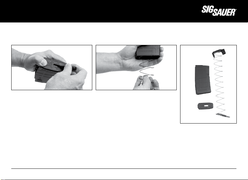
8.6 Cleaning the Magazine
Magazines should be cleaned whenever the rifle is cleaned as preventive maintenance.
FIG 39 MAGAZINE
1. Use a brush to clean inside the body.
2. Clean with a rag and CLP then wipe dry.
3. Clean follower and dry completely.
The magazine body should be kept dry. Any oil or solvent left behind will attract dirt and debris causing undue wear and
possibly feeding issues.
™
www.sigsauer.com
67
Page 68
8.7 Cleaning the Pushrod and Gas Valve
A cotton patch and a soft brush can be used to clean the gas valve and the pushrod assembly.
1. Clean all fouling from the Push Rod.
2. Clean all fouling from the gas valve.
3. Clean the ports of the gas valve. Soaking the valve in solvent for 10 minutes before attempting to remove fouling will
make it easier to clean.
68
www.sigsauer.com
Page 69
when it counts
9.0 Reassembly
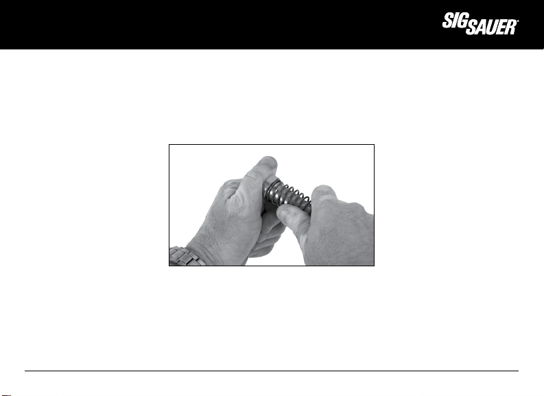
9.1 Recoil Buffer and Action Spring
1. Slide the action spring over the recoil buffer and snap it into place by using a clockwise twisting motion as you press it
forward.
FIG 40 SPRING TO BUFFER
™
www.sigsauer.com
69
Page 70
2. Insert the action spring into the receiver extension tube.
FIG 41 ACTION SPRING AND BUFFER
STARTED INTO RECEIVER EXTENSION
3. Push the recoil buffer back into the receiver extension until the buffer retaining plunger engages the face of the buffer
and holds it into the receiver extension.
FIG 42 BUFFER HELD INTO RECEIVER EXTENSION
70
www.sigsauer.com
Page 71
when it counts
9.2 Extractor
1. Fit extractor to bolt body by holding bolt in one hand; and
2. While applying pressure with thumb over the spring end of the extractor, slide extractor pin into hole until ends are
flush with bolt body.
FIG 43 EXTRACTOR TO BOLT BODY
™
www.sigsauer.com
71
Page 72

9.3 Bolt to Bolt Carrier
WARNING:
THE BOLT CAM PIN MUST BE INSTALLED OR THE RIFLE WILL SUFFER A CATASTROPHIC FAILURE WHICH COULD RESULT IN
SERIOUS INJURY OR DEATH TO THE OPERATOR.
DO NOT INTERCHANGE BOLT ASSEMBLIES FROM ONE RIFLE TO ANOTHER. DOING SO COULD RESULT IN SERIOUS INJURY
OR DEATH TO THE OPERATOR.
72
www.sigsauer.com
Page 73
when it counts
1. Re-insert the bolt into the bolt carrier with the extractor oriented to the right side of the bolt carrier; and
Alignment of Bold and Carrier
FIG 44 ALIGN BOLT INTO CARRIER BODY
2. Pull the bolt forward to the unlocked position; and align the cam pin hole inserting the cam pin into the bolt; and
3. Insert the firing pin into the tail shaft of the bolt.
Camp Pin installed
FIG 45 CAM PIN BACK INTO BOLT AND CARRIER
™
www.sigsauer.com
73
Page 74

CAUTION: THE FIRING PIN MUST BE FULLY INSERTED INTO THE BOLT CARRIER PRIOR TO INSTALLATION OF THE FIRING PIN
RETAINING PIN. THE RETAINING PIN MUST PASS BETWEEN THE LARGE SHOULDER OF THE FIRING PIN AND THE HEAD OF
THE FIRING PIN.
FIG 46 FIRING PIN INSERTED INTO BOLT/CARRIER
4. Re-install the firing pin retaining pin into the bolt carrier from left to right.
5. Point the bolt carrier assembly with the bolt face upward and ensure the firing pin is properly retained in the carrier by
lightly slapping the bolt face back into the carrier (locked position). The firing pin should NOT fall out of the carrier.
74
www.sigsauer.com
Page 75

when it counts
9.4 Bolt Carrier Assembly to Upper Receiver
1. Position the upper receiver assembly with the open bottom facing upward; and
2. Insert the charging handle into the slotted key way of the receiver and push it forward slightly.
3. Take the bolt carrier assembly with the bolt pulled completely forward (unlocked position) and set it into the charging
handle.
4. Simultaneously push the bolt carrier assembly and the charging handle forward until the bolt and the charging handle
lock into place.
FIG 47 REINSTALLATION OF THE BOLT CARRIER ASSEMBLY TO UPPER RECEIVER
™
www.sigsauer.com
75
Page 76

9.5 Rejoining Upper and Lower Receivers
To aid in steps 1-3, manually cock the hammer by pushing it down until it is held in place then rotate the fire control
selector to SAFE.
1. Position the upper and lower receivers to align the pivot pin (front pin) holes.
2. Push the pivot pin from right to left until the head of the pivot pin is flush against the receiver. You will feel it captured
by the detent pin.
3. Close the receivers together and push the takedown pin (rear pin) from right to left until the head of the takedown pin
is flush against the receiver. You will feel it captured by the detent pin as you did the pivot pin.
9.6 Quad Rail Reassembly
1. Pre-assemble the rail clamp and quad key to the lower rail section leaving the two (2) clamp screws loose.
FIG 48 QUAD KEY AND RAIL CLAMP PRE-ASSEMBLED
76
www.sigsauer.com
Page 77

when it counts
2. Place the upper rail section over the barrel nut interlocking the tab into the upper receiver pocket.
FIG 49 RE-INSTALLATION OF UPPER RAIL SECTION WITH INTERLOCKING TAB HIGHLIGHTED
3. Place the lower rail section over the barrel nut ensuring that the key is seated into the groove of the barrel nut.
FIG 50 RE-INSTALLATION OF LOWER RAIL SECTION
™
www.sigsauer.com
77
Page 78

4. Install the four (4) rail screws using a 5/32” hex wrench. Tighten the screws to 60 inch pounds (7 Newton meters).
FIG 51 TIGHTENING OF RAIL SECTION SCREWS
5. Tighten the clamp screws to 70 inch pounds (8 Newton meters) using a 1/8” torque wrench.
6. Repeat step 5 one time.
FIG 52 TIGHTENING OF RAIL CLAMP SCREWS
78
www.sigsauer.com
Page 79

when it counts
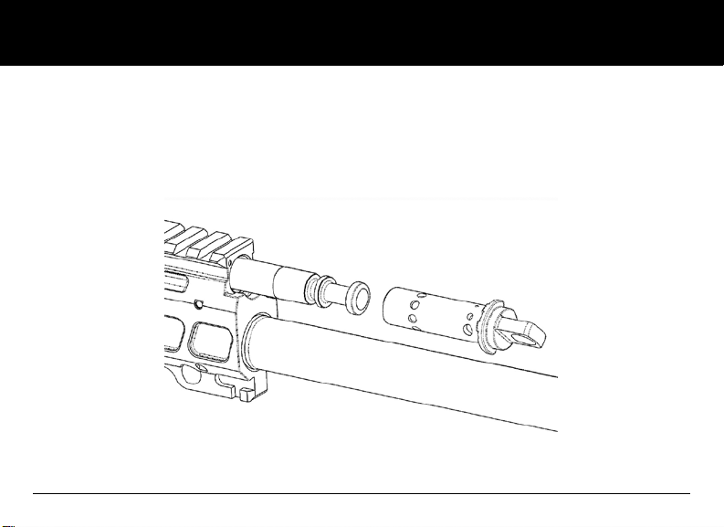
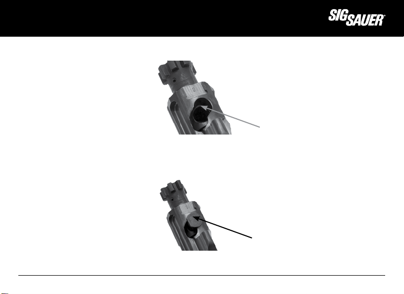
9.7 Pushrod and Gas Valve re-assembly
To simplify the process of reinstalling the pushrod assembly, always pre-assemble the gas valve into the pushrod prior to
attempting reinsertion of the pushrod through the gas block. This will help in guiding the pushrod into the upper receiver.
FIG 53 PUSH ROD AND GAS VALVE
1. Install the pushrod assembly through the front of the
gas block with the flat side of the spring guide facing
downward toward the barrel nut.
FIG 54 ALIGNMENT OF SPRING RETAINER TO BARREL NUT
™
www.sigsauer.com
79
Page 80
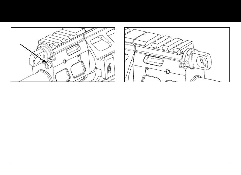
Detent
FIG 55 GAS VALVE ROTATION (STEP 3) FIG 56 FINAL GAS VALVE POSITION
To Re-install the gas valve and push rod:
1. Assemble the gas valve onto the pushrod. This will aid in assembly.
2. Slide the push rod and valve back through the gas block until the valve flange contacts the gas block.
3. Rotate the valve clockwise until the flange contacts the detent on the lower right corner of the gas block, depress the
detent and rotate the valve clockwise again until it is the “Normal” operating position.
4. Check valve rotation from “Normal” to “Adverse”. The valve should rotate freely and not be restricted in anyway.
ALWAYS PERFORM A FUNCTION CHECK OF THE RIFLE ANYTIME YOU FIELD STRIP IT FOR CLEANING OR MAINTENANCE.
FOLLOW THE STEPS BELOW. SHOULD THE RIFLE NOT PASS THESE SIMPLE STEPS DO NOT ATTEMPT TO FIRE THE RIFLE,
AND CONTACT SIG SAUER OR AN AUTHORIZED SERVICE TECHNICIAN.
80
www.sigsauer.com
Page 81

when it counts
10.0 Perform a Function Check of the SIG716 Semi-Automatic Rifle
With the SIG716 rifle and one UNLOADED magazine perform a function check of the rifle as outlined below in steps 1-13.
THE FUNCTION CHECK SHOULD ALWAYS BE DONE AFTER CLEANING AND ASSEMBLING THE RIFLE. ALWAYS VISUALLY
AND PHYSICALLY CLEAR THE FIREARM FIRST!
SIG716 (SAFE/SEMI ONLY)
1. Insert an empty magazine into the magazine well until it locks into place.
2. Pull down on the magazine to ensure it is locked in place by the magazine catch.
3. Pull charging handle fully back then push it forward into locked position. The bolt carrier should now be held to the
rear by the bolt catch.
4. Depress the magazine catch .
5. The magazine should fall free of the rifle under its own weight (unloaded).
6. Push the top of bolt catch to release the bolt carrier. The bolt carrier will travel forward into the locked position.
7. Rotate the fire control selector to SAFE.
8. Press the trigger to the rear. The hammer should NOT fall.
9. Rotate the fire control selector to SEMI.
10. Press the trigger to the rear and DO NOT RELEASE IT. You should hear a loud click as the hammer falls. Keep the
trigger pressed to the rear; and
11. Pull the charging handle to the rear and release it while keeping trigger pulled. Hammer should not fall but be held
in the cocked position by the disconnect.
12. Release the trigger. A click should be heard as the hammer is caught by the trigger sear.
13. Press the trigger to the rear again and the hammer should fall.
™
www.sigsauer.com
81
Page 82
11.0 Lubrication
Using lubricant designed for use on firearms, lightly apply to the contact areas of the following components:
Upper Receiver Assembly
• Forward assist.
• Ejection port cover spring and latch.
• Charging handle latch and spring.
• Front sight detent.
• Rear sight windage screw and detent.
• Gas valve body.
• Pushrod and spring.
Valve Body
82
www.sigsauer.com
Page 83
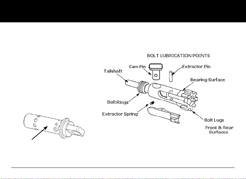
Bolt and Carrier Assembly
• Extractor spring.
• Tailshaft
• Cam Pin.
• Bolt Rings.
• Locking Lugs.
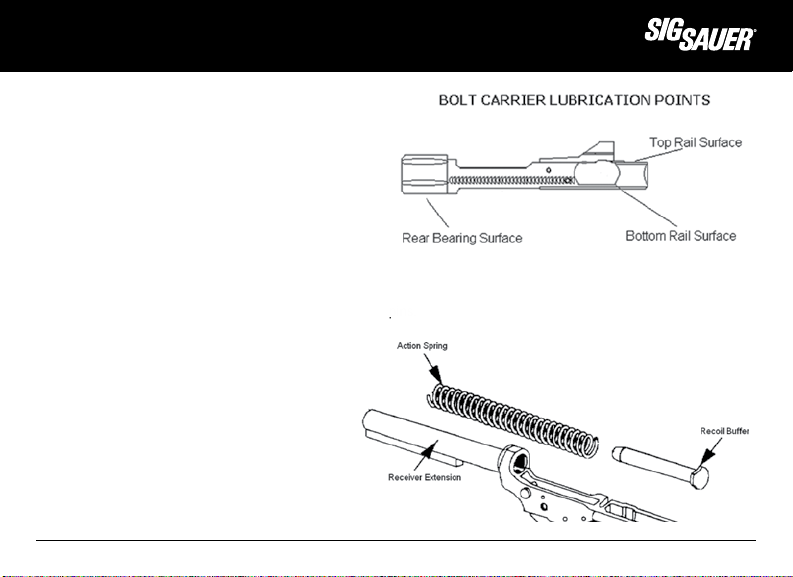
• Rail Surfaces, top and bottom.
• Bolt bearing surface.
Lower Receiver Assembly
• Fire control springs, pins, detents, pivot and takedown pins.
• Trigger Sear Surface, Disconnect Surface.
• Buttstock release levers.
• Recoil buffer
• Action spring
• Receiver extension
when it counts
™
www.sigsauer.com
83
Page 84

12.0 Transportation and Storage
When transporting your firearm to and from shooting activities, keep it unloaded for your safety and for the safety
of others. When storing your firearm, keep it separated from ammunition, under lock and key if possible, and out of the
reach of children and other inexperienced or unauthorized persons.
WARNING - STORAGE:
Never place or store any firearm in such a manner that it may be dislodged. Firearms should always be stored securely
and unloaded, away from children and other unauthorized users. Use the locking device originally supplied with this
firearm for storage. The use of a locking device or safety lock is only one aspect of responsible firearms storage. For
increased safety, firearms should be stored unloaded and locked in a location that is both separate from their ammunition
and inaccessible to children and any other unauthorized person.
STORE SECURELY & UNLOADED
84
www.sigsauer.com
Page 85

This page intentionally left blank.
when it counts
™
www.sigsauer.com
85
Page 86

13.0. Service and Replacement Parts Policy
Parts Policy
Our Service Department maintains a full complement of replacement parts. Even though most gunsmiths have the
knowledge, training, and the ability to make necessary repairs to your firearm, the skill and workmanship of any
particular gunsmith is totally beyond our control.
Should your firearm ever require service, we strongly recommend that you return it to SIG SAUER Inc. A firearm is a
precision instrument and some replacement parts will require individual fitting to ensure correct operation. A wrong part,
improper fitting, or incorrect mechanical adjustment may result in an unsafe condition or dangerous malfunction, damage
to the firearm, or cause possible serious injury to the shooter or others.
IF ANY PART IS ORDERED WITHOUT RETURNING THE FIREARM TO SIG SAUER Inc., the customer bears full responsibility
for ensuring that the part supplied is correct for their particular firearm and is properly installed and fitted by a qualified
gunsmith.
SIG SAUER Inc. CANNOT BE RESPONSIBLE FOR THE FUNCTIONING OF ANY FIREARM IN WHICH REPLACEMENT PARTS ARE
INSTALLED BY OTHERS.
86
www.sigsauer.com
Page 87
when it counts
WARNING - PARTS PURCHASE:
It is the purchaser’s responsibility to be absolutely certain that any parts ordered from the factory are correctly fitted
and installed. Firearms are complicated mechanisms and IMPROPER FITTING OF PARTS MAY RESULT IN A DANGEROUS
MALFUNCTION, DAMAGE TO THE FIREARM, AND SERIOUS INJURY TO THE SHOOTER AND OTHER PERSONS. The purchaser
and installer of parts must accept full responsibility for the correct adjustment and functioning of the rifle after such
installation.
PARTS MUST FIT CORRECTLY
™
www.sigsauer.com
87
Page 88

Service Policy
If you have questions concerning the performance or servicing of your rifle, please write or call:
SIG SAUER Inc.
Attention: Customer Service
18 Industrial Drive, Exeter, NH 03833
Phone: (603) 772-2302
Fax: (603) 772-9082
IF YOU DO NOT UNDERSTAND THE INSTRUCTIONS FOR OPERATING YOUR RIFLE, IT IS YOUR RESPONSIBILITY TO CALL OUR
CUSTOMER SERVICE DEPARTMENT AT (603) 772-2302 BEFORE USING YOUR RIFLE.
14.0. Shipping Firearms for Repair
Returning Your Firearm For Service In the event you need to return your rifle to the SIG SAUER
Service Department, here’s what to do:
1. The first step is to contact Customer Service at (603) 772-2302 for an RMA number. This number allows SIG SAUER to
track the status of your return from its receipt at SIG SAUER through its return to you. Please do not send your firearm
until you obtain an RMA number.
2. Make sure that the chamber and magazine(s) are unloaded and that no ammunition is included with your returned
firearm.
3. Package the firearm securely to prevent damage. Enclose a letter which includes your name, street address, daytime
phone number, model and serial number, and a detailed description of the problem you have experienced or the work
you want performed. With the exception of extra magazines, do not include scopes, mounts, or other accessories.
88
www.sigsauer.com
Page 89

when it counts
4. Generally, an individual may ship firearms to the manufacturer for repair or service. Some states and localities,
however, prohibit this. If you live in such an area, the firearms must be shipped by and returned to a Federally Licensed
Firearms Dealer.
5. Federal law prohibits persons who do not possess a Federal Firearms License from shipping a firearm via the U.S.
Postal Service. (Note: any shipment of firearms outside U.S. borders is subject to the export laws of the United States and
to the valid laws of the specific country, which you must strictly follow; prior to exporting any firearm you should seek
legal counsel.)
6. SIG SAUER is not responsible for any firearm until it is received, nor for damage incurred during shipment.
7. Ship your firearms insured and prepaid (we do not accept collect shipments) to:
SIG SAUER Inc.
Attention: Service Department
18 Industrial Drive Exeter, NH 03833
This instruction manual should always accompany this rifle and be transferred with it upon change of ownership.
WARNING - SHIPPING
WARNING: BEFORE SHIPPING ANY FIREARM, BE ABSOLUTELY CERTAIN THAT THE FIREARM AND ITS MAGAZINE ARE
UNLOADED. DO NOT SHIP AMMUNITION WITH A FIREARM.
™
www.sigsauer.com
89
Page 90

ORDER PARTS
In the event you want to order parts for your SIG716 rifle, contact Customer Service at (603) 772-2302. Have available the
serial number of your rifle and the part diagram number for the part(s) you wish to order. A parts list and diagram of the
rifle is provided in sections 14.0 and 14.1.
15.0 Parts List
1 1800082 RECEIVER, SEMI, MACHINED
2 1700114 HAMMER ASSY, SEMI
3 1700086 HAMMER SPRING
4 1700117 DISCONNECTOR, SEMI
5 1700104 DISCONNECT SPRING
6 1700119 TRIGGER, SEMI
7 1700103 TRIGGER RETURN SPRING
8 1800012 BOLT CATCH
9 1700091 BOLT CATCH PLUNGER
10 1700092 BOLT CATCH SPRING
11 1700093 BOLT CATCH PIN
12 1800061 TAKE DOWN PIN
13 1511116 TAKE DOWN PLUNGER SPRING
14 1511085 TRIGGER GUARD ASSY
15 1700106 PIN, SLOTTED SPRING
16 1800056 PIVOT PIN
17 1700080 SAFETY DETENT
18 1800140 TAKEDOWN SPRING
19 1700144 TAKE DOWN & PIVOT PIN DETENT
20 1800073 EXTENSION TUBE
21 1511133 LOCK NUT, RECEIVER EXTENTION
22 1700107 BUFFER RETAINING PIN
23 1700108 BUFFER RETAINING SPRING
24 1700061 BUFFER ASSY, CARBINE
25 1800024 ACTION SPRING
26 1800010 AMBI MAG CATCH ASSY
27 1511080 MAG CATCH BUTTON
28 1511079 MAG CATCH SPRING
29 1700137 TRIGGER PIN
30 1700136 HAMMER PIN
31 1700135 TENSIONING PLUNGER
32 1511134 SPACER
33 1700225 FIRE CONTROL SELECTOR, SEMI
34 1700183 PISTOL GRIP MIAD
90
www.sigsauer.com
Page 91

when it counts
™
35 1700257 MAGPUL BUTTSTOCK, ACS
36 1800046 UPPER RECEIVER
37 1700026 PIN, SLOTTED SPRING
38 1700028 FORWARD ASSIST ASSY
39 1700027 FORWARD ASSIST SPRING
40 1800038 EJECTION PORT COVER ASSY
41 1800049 COVER PIN
42 1700036 COVER SPRING
43 1800078 OP ROD BUSHING
44 1800086 BOLT CARRIER, SEMI
45 1800116 FIRING PIN RETAINING PIN
46 1800007 FIRING PIN
47 1800025 FIRING PIN SPRING
48 1800013 CAM PIN
49 1800042 BOLT ASSY
50 1800041 CHARGING HANDLE ASSY
51 1800021 RAIL ADAPTER UPPER
52 1800022 RAIL ADAPTER LOWER
53 1700124 RAIL ADAPTER CLAMP CAP
54 1800072 CLAMP KEY
55 1700193 FLAT HEAD SCREW, 10-32 X 7/16L
56 1700194 SCREW, CAP LOW HEAD, 10-32 X 3/8 L
57 1800130 GAS BLOCK
58 1700053 GAS BLOCK RETAINING PIN
59 1800017 BARREL NUT
60 1800110 BARREL ASSY, 16 INCH
61 1511848 FLASH SUPPRESSOR A2 TYPE, 5/8-24
62 1511900 CRUSH WASHER, 556R
63 1511292 STOP PIN SPRING
64 1800143 GAS VALVE PLUNGER
65 1511292 DETENT SPRING
66 1800131 GAS VALVE
67 1700041 PIN, SLOTTED SPRING
68 1800027 OP ROD ASSY
www.sigsauer.com
91
Page 92

16.0 Parts Diagram
46
47
44
45
48 50
49
35
20
25
21
32
38
36
42
40
41 43
60
33
24
18
19
1
31
34
97
17
93
14
29
30
28
27
12
2
3
4
5
6
8
26
9
10
7
54
52
53
55
56
37
11
16
19
13
15
22
23
39
CHECKED BY:
DRAWN BY:
THIS ENTIRE DOCUMENT AND ALL INFORMATION THEREON IS PROPRIETARY
AND IS THE EXCLUSIVE PROPERTY OF SIG SAUER, INC. EXETER, NH, U.S.A. AND
SHALL NOT BE REPRODUCED, DUPLICATED OR COPIED IN WHOLE OR IN PART,
DISCLOSED OR MADE AVAILABLE TO ANY OTHER PERSON, FIRM,
CORPORATION, OR ENTITY OR OTHERWISE USED WITHOUT THE PRIOR
WRITTEN PERMISSION OF SIG SAUER, INC.
THIS DRAWING OR PRINT MUST BE RETURNED TO THE OWNER UPON
COMPLETION OF THE PURPOSE FOR WHICH SUCH PERMISSION MAY BE
GRANTED.
ENG APPR:
MFG APPR:
APPROVALS DATE
JPB 6/28/11
92
www.sigsauer.com
Page 93

when it counts
38
36
42
40
41 43
51
67
60
2
3
4
8
54
52
53
55
59
66
57
63
64
65
61
62
56
37
11
39
58
DRAWNBYENG
APPR
ECO
DATE
DESCRIPTION
REV
REVISION HISTORY
D
C
1
2
00
JPB
INITIAL RELEASE
01707
™
www.sigsauer.com
93
Page 94

SIG SAUER® Limited Lifetime Firearms Warranty
SIG SAUER warrants that the enclosed firearm was originally manufactured free of defects in material, workmanship and
mechanical function. For the lifetime of the original purchaser, SIG SAUER agrees to correct any defect in the firearm
for the original purchaser by repair, adjustment or replacement, at SIG SAUER’s option, with the same or comparable
quality components (or by replacing the firearms at SIG SAUER’s option); provided, however, that the firearm is returned
unloaded and freight prepaid to SIG SAUER at 18 Industrial Drive, Exeter, NH 03833.
This limited warranty is null and void if the firearm has been misused, damaged (by accident or otherwise), fired with
handloaded, reloaded or improper ammunition, fired with an obstruction in the barrel, damaged through failure to provide
reasonable and necessary maintenance as described in the manual accompanying the firearm, or if unauthorized repair
or any alteration, including of a cosmetic nature, has been performed on the firearm. This limited warranty does not apply
to normal wear and tear of any parts.
Subject to the foregoing, this limited warranty confers the right to have the covered firearm or its parts repaired, adjusted
or replaced exclusively upon the original purchaser, which right is not transferable to any other person. No implied
warranties of any kind are made herein and this warranty does not apply to any accessory items attached or appurtenant
to the firearm. In no event shall SIG SAUER be liable for any incidental or consequential damages arising from or in
connection with this limited warranty.
94
www.sigsauer.com
Page 95

Notes:
when it counts
™
www.sigsauer.com
95
Page 96

P/N 1800058 REV 01
when it counts
™
www.sigsauer.com
FOR PRODUCT SERVICE ON THIS MODEL,
PLEASE CALL (603) 772-2302
18 Industrial Drive, Exeter, NH 03833 USA
 Loading...