

Sigma K1000 Series Operation & Maintenance Manual
Sigma
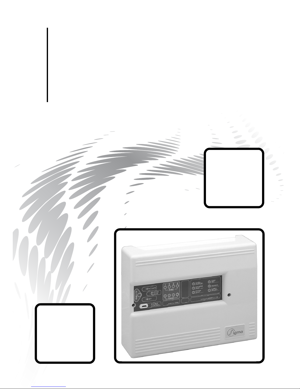
K1000 Series 1, 2, 4 & 6 Zone
Fire Control Panels
Operation and Maintenance Manual
Man-1048 Issue 05 October 2009

Sigma K1000 Series 1, 2, 4 & 6 Zone Fire Control Panels Operation and Maintenance Manual
CONTENTS
Contents .......................................................................................................... Page
Safety & Installation..................................................................................................2
Installation - continued ..............................................................................................3
Front Panel Controls & Front Panel Indications.........................................................3
Front Panel Indications - continued,...........................................................................4
Internal Indicators .....................................................................................................5
Internal Controls .......................................................................................................6
Internal Controls - continued & T erminal Functions ....................................................7
T erminal Functions - continued ..................................................................................8
Annexe
T ypical wiring Connections & Use Of Aux.24V Output .............................................1
Sigma Installation & Mains Supply Connection..........................................................2
Connections T o Detectors & Sounders......................................................................3
K1002 PCB Layout (1 & 2 Zone), K1006 PCB Layout (4 & 6 Zone)......................4

Sigma K1000 Series 1, 2, 4 & 6 Zone Fire Control Panels Operation and Maintenance Manual
IMPORTANT
READ THIS SECTION FIRST!
1.1 Suppliers of articles for use at work are required under section 6 of the Health and
Safety at Work Act 1974 to ensure as reasonably as is practical that the article will be
safe and without risk to health when properly used.An article is not regarded as properly used if it is used "without regard to any relevant information or advice" relating to
its use made available by the supplier.
1.2 This product should be installed, commissioned and maintained by or under the supervision of competent persons according to good engineering practice and:-
i) IEE regulations for the electrical equipment of buildings.
ii) Codes of practice.
iii) Statutory requirements.
iv) Any instructions specifically advised by the manufacturer.
According to the provisions of the act you are therefore requested to take such steps as
are necessary to ensure that any appropriate information about this product is made
available by you to anyone concerned with its use.
1.3 This equipment is designed to be operated from 220-240V AC mains supplies and is of
class I construction. As such it
must be connected to a protective earthing conductor in
the fixed wiring of the installation.
1.4 Failure to ensure that all conductive accessible parts of this equipment are adequately
bonded to the protective earth will render the equipment unsafe.
SAFETY
Page 2 of 10
INSTALLATION
2.1 Remove the front panel by unscrewing the two Socket screws with a key. This will
expose the internal equipment and three fixing holes.
2.2 Place the circuit boards in a safe area for later installation.
2.3 Locate the unit on the wall in the agreed position and mark the fixing points through the
dished mounting holes (see annex 2). Drill and fit suitable wall plugs and screw the
panel to the wall.
2.4 Use the knockouts provided to make off the cables. Earth or drain wires should be
kept as short as is practical and be connected to a metal cable gland making sound
electrical contact with the enclosure.
2.5 If additional or larger cable entries are required, any swarf and debris
must be cleared
from the inside of the equipment. Failure to do this will result in equipment malfunction
and could represent a danger to building occupants.
2.6 The mains fuse must only be replaced with a 2 amp fuse conforming to BS:4265.

Sigma K1000 Series 1, 2, 4 & 6 Zone Fire Control Panels Operation and Maintenance Manual
3. 1 Enable Controls
No Controls are enabled unless the enable controls key is inserted. While the enable
controls key is inserted the buzzer will beep every few seconds.
3. 2 Silence Alarm Switch
T o silence an alarm activated by operation of a detection zone, press the silence alarm
button. The alarm silenced indicator will illuminate and the sounders will stop.
To mute the fault buzzer , press the silence alarm switch. The fault buzzer will now beep
every few seconds.
3. 3 Reset & Lamp Test Switch
All Indicators may be illuminated, for testing purposes, by pressing the reset and lamp
test switch. If any Zones are in fire condition, these will reset provided that the silence
alarms switch has first been operated and the input signal e.g. Break glass unit has
been restored to normal.
3. 4 Evacuate Switch
Press the evacuate switch to operate the Sounder Circuits. The Common Fire indicator
will be illuminated and the buzzer will sound the alarm tone.
FRONT P ANEL CONTROLS
2.7 This equipment is designed to be powered from the 220 - 240V C mains supply. The
mains connection must include a protective Earth conductor to the requirements of
BS:7671 (see annex 2).
2.8 The mains supply must be from a separate dedicated fused spur labelled "FIRE
ALARMS DO NOT SWITCH OFF".
2.9 The installation should be carried out by or under the supervision of a competent
person and in accordance with the requirements of BS:7671:1992 requirements for
electrical installation, BS:5839: Part 1:1988 fire detection and alarm systems for buildings.
2.10 Connection of the 24V battery supply should be carried out with great care and respect.
Misconnection or short circuiting of the battery terminals
will result in FIRE.
2. 11 The system fuse F2 should only be replaced with mains and battery disconnected.
Page 3 of 10
INST ALLATION -
Continued
FRONT P ANEL INDICA TIONS
4. 1 Supply Healthy Indicator
Under normal conditions only the green supply healthy indicator is illuminated. The
system healthy indicator will extinguish in the event of:-
(1) Mains Failure
(2) Battery Disconnection.
(3) System Fuse Failure
(4) Total Power Failure
(5) Battery Fuse Failure
 Loading...