

Page 1
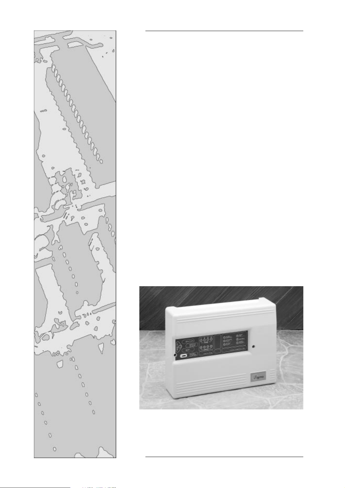
Sigma
K1000 Series
1, 2, 4 & 6 Zone
Fire Control Panels
Operation and
Maintenance Manual
Issue 04 Sept. 1998
Sigma K1000 Series 1, 2, 4 & 6 Zone Fire Control Panels Operation and Maintenance Manual
Page 2

CONTENTS
Contents .......................................................................................................... Page
Safety & Installation..................................................................................................2
Installation - continued ..............................................................................................3
Front Panel Controls & Front Panel Indications.........................................................3
Front Panel Indications - continued,...........................................................................4
Internal Indicators .....................................................................................................5
Internal Controls .......................................................................................................6
Internal Controls - continued & T erminal Functions ....................................................7
T erminal Functions - continued ..................................................................................8
Annexe
T ypical wiring Connections & Use Of Aux.24V Output .............................................1
Sigma Installation & Mains Supply Connection..........................................................2
Connections T o Detectors & Sounders......................................................................3
K1002 PCB Layout (1 & 2 Zone), K1006 PCB Layout (4 & 6 Zone)......................4
Sigma K1000 Series 1, 2, 4 & 6 Zone Fire Control Panels Operation and Maintenance Manual
Page 3

SAFETY
IMPORTANT
READ THIS SECTION FIRST!
1.1 Suppliers of articles for use at work are required under section 6 of the Health and
1.2 This product should be installed, commissioned and maintained by or under the supervi-
Safety at Work Act 1974 to ensure as reasonably as is practical that the article will be
safe and without risk to health when properly used.An article is not regarded as properly used if it is used "without regard to any relevant information or advice" relating to
its use made available by the supplier.
sion of competent persons according to good engineering practice and:-
i) IEE regulations for the electrical equipment of buildings.
ii) Codes of practice.
iii) Statutory requirements.
iv) Any instructions specifically advised by the manufacturer.
According to the provisions of the act you are therefore requested to take such steps as
are necessary to ensure that any appropriate information about this product is made
available by you to anyone concerned with its use.
1.3 This equipment is designed to be operated from 220-240V AC mains supplies and is of
class I construction. As such it
the fixed wiring of the installation.
1.4 Failure to ensure that all conductive accessible parts of this equipment are adequately
bonded to the protective earth will render the equipment unsafe.
INSTALLATION
2.1 Remove the front panel by unscrewing the two Socket screws with a key. This will
expose the internal equipment and three fixing holes.
2.2 Place the circuit boards in a safe area for later installation.
2.3 Locate the unit on the wall in the agreed position and mark the fixing points through the
dished mounting holes (see annex 2). Drill and fit suitable wall plugs and screw the
panel to the wall.
2.4 Use the knockouts provided to make off the cables. Earth or drain wires should be
kept as short as is practical and be connected to a metal cable gland making sound
electrical contact with the enclosure.
must be connected to a protective earthing conductor in
2.5 If additional or larger cable entries are required, any swarf and debris
from the inside of the equipment. Failure to do this will result in equipment malfunction
and could represent a danger to building occupants.
2.6 The mains fuse must only be replaced with a 2 amp fuse conforming to BS:4265.
Sigma K1000 Series 1, 2, 4 & 6 Zone Fire Control Panels Operation and Maintenance Manual
Page 2 of 10
must be cleared
Page 4

INST ALLATION -
2.7 This equipment is designed to be powered from the 220 - 240V C mains supply. The
mains connection must include a protective Earth conductor to the requirements of
BS:7671 (see annex 2).
2.8 The mains supply must be from a separate dedicated fused spur labelled "FIRE
ALARMS DO NOT SWITCH OFF".
2.9 The installation should be carried out by or under the supervision of a competent
person and in accordance with the requirements of BS:7671:1992 requirements for
electrical installation, BS:5839: Part 1:1988 fire detection and alarm systems for buildings.
2.10 Connection of the 24V battery supply should be carried out with great care and respect.
Misconnection or short circuiting of the battery terminals
2. 11 The system fuse F2 should only be replaced with mains and battery disconnected.
Continued
FRONT P ANEL CONTROLS
3. 1 Enable Controls
No Controls are enabled unless the enable controls key is inserted. While the enable
controls key is inserted the buzzer will beep every few seconds.
will result in FIRE .
3. 2 Silence Alarm Switch
T o silence an alarm activated by operation of a detection zone, press the silence alarm
button. The alarm silenced indicator will illuminate and the sounders will stop.
T o mute the fault buzzer, press the silence alarm switch. The fault buzzer will now beep
every few seconds.
3. 3 Reset & Lamp Test Switch
All Indicators may be illuminated, for testing purposes, by pressing the reset and lamp
test switch. If any Zones are in fire condition, these will reset provided that the silence
alarms switch has first been operated and the input signal e.g. Break glass unit has
been restored to normal.
3. 4 Evacuate Switch
Press the evacuate switch to operate the Sounder Circuits. The Common Fire indicator
will be illuminated and the buzzer will sound the alarm tone.
FRONT P ANEL INDICA TIONS
4.1 Supply Healthy Indicator
Under normal conditions only the green supply healthy indicator is illuminated. The
system healthy indicator will extinguish in the event of:-
(1) Mains Failure
(2) Battery Disconnection.
(3) System Fuse Failure
(4) Total Power Failure
(5) Battery Fuse Failure
Sigma K1000 Series 1, 2, 4 & 6 Zone Fire Control Panels Operation and Maintenance Manual
Page 3 of 10
Page 5

FRONT P ANEL INDICATIONS -
4. 2 System Fault Indicator
The system fault indicator will illuminate under any abnormal condition. Certain conditions
may be diagnosed without looking inside the enclosure as follows:-
(1) System Fault on. Supply Healthy off = Power failure or system fuse failure.
(2) System Fault on, Zone Fault on = Zone O/C or S/C in indicated zone.
(3) System Fault on, Zone test on = Zone indicated in test mode.
(4) System Fault on, Disabled Led on = Zone indicated in disabled/isolated mode.
(5) System Fault on. Sounder Fault on = Sounder Circuit O/C or S/C Fault.
4.3 Alarm Silenced Indicator
The alarm silenced indicator should only be accompanied by one or more steady fire
indicators, and indicates that the sounders have been silenced.
Operation of subsequent fire zones or the evacuate switch will extinguish the alarm
silenced indicator .
4.4 Zone Fault Indicator
Illumination of a zone fault indicator may mean that one or more trigger devices are
inoperative and requires immediate attention.
Zone fault indicators will illuminate in the event of:-
Continued
(1) Disconnection or severance of zone wiring
(2) Short Circuit on zone wiring
(3) Removal of a sensor from its base
(4) Disconnection of the end of line monitor resistor, or active end of line unit (LCMU)
4. 5 Fire Indicators
Upon detection of a fire the red zone fire alarm indicator will flash to give warning of
the area (zone) in fire and the common fire indicator will be illuminated. This will be
accompanied by a pulsing buzzer within the control panel and the operation of the
sounders.
4. 6 Sounder Fault Indicator
The sounder fault indicator and the system fault indicator will be illuminated if a sounder
circuit is open or short circuit.
4. 7 Zone Test Indicator
The zone test indicator will be illuminated if one or more zones are in zone test mode.
4. 8 Disabled Indicator
The disabled indicator will be illuminated if :(A) one or more zones are in the disabled mode. This is accompanied by the zone fault
indicator .
(B) The Sounder disable or remote signal, disable switch is operated. This Indicator will
be accompanied by the system fault indicator.
4. 9 Common Fire/ Evacuate Indicator
The common fire indicator will be illuminated if the panel is in an alarm condition or in
an evacuate condition.
Sigma K1000 Series 1, 2, 4 & 6 Zone Fire Control Panels Operation and Maintenance Manual
Page 4 of 10
Page 6

INTERNAL INDICA TORS
123456
SOUNDER
S/C FAULT
5.1 Sounder S/C Fault Indicator
This indicator will illuminate in the event of a short circuit on one of the sounder lines.
5. 2 Sounder O/C Fault Indicator
This indicator will illuminate in the event of a open circuit on one of the sounder lines.
5. 3 Fuse Fault Indicator
This indicator will illuminate in the event of :(A) Auxiliary fuse failure.
(B) System fuse failure.
5.4 Earth Fault Indicator
This indicator will illuminate in the event of a positive or negative earth fault. (i.e. Field
wiring connected to earth).
5. 5 Rem Fire Sig disabled indicator
This indicator will illuminate in the event of the Rem Fire Sig disable switch being operated.
SOUNDER
O/C FAULT
FUSE
FAULT
EARTH
FAULT
REM. SIG
DISABLED
SOUNDER
DISABLED
5. 6 Sounder Disable Indicator
This indicator will illuminate in the event of the Sounder disable switch being operated.
INTERNAL CONTROLS
6.1 The panel has an internal DIL Switch, which provides the following functions:-
One zone Sigma
Normal switch positions
Six zone Sigma
Normal switch positions
Sigma K1000 Series 1, 2, 4 & 6 Zone Fire Control Panels Operation and Maintenance Manual
Page 5 of 10
Page 7

INTERNAL CONTROLS -
Continued
T wo zone Sigma
Normal switch positions
TERMINAL FUNCTIONS
Smoke Detection Circuits
7.1 One to six smoke detection circuits are provided and supply 28 Volts ( + 5%) for the
operation of trigger devices, (smoke detectors or heat detectors). Terminals for the
smoke detection circuits are labelled Z1+ and Z1- to Z6+ and Z6- for positive and
negative connections respectively. It is important to observe the polarity of these
connections for correct operation of the system.
7.2 A 6K8 end of line resistor must be fitted to the last device on the smoke detection
circuit for correct operation of the monitoring functions. Alternatively for greater system
integrity a line continuity monitoring unit (LCMU) may be fitted.
Sounder Circuits
8.1 Two sounder circuits outputs are provided and are labelled (S1 +&-) &( S2 + &-).
These outputs will operate together upon activation of a smoke detection zone, operation of the evacuate switch or the remote Alarm input. Each sounder circuit is protected by a 500mA fuse.
Four zone Sigma
Normal switch positions
8.2 Both outputs are monitored against open and short circuit faults in the field wiring.
Any such faults are annunciated by the front panel system fault indicator immediately.
8.5 The sounder circuit is normally fitted with a 20K end of line monitoring resistor.
Fault VFCO Contacts
9.1 Volt free contacts are provided for remote signalling or plant shutdown on the occurrence
of any fault condition.
Fire VFCO Contacts
10.1 V olt free contacts are provided for remote signalling or plant shut down on the
occurrence of any fire condition or evacuate condition.
10.2 All contacts are rated at 30V DC 1 Amp maximum and should under no circumstances
be used to switch greater voltages or currents (see annex 3).
Sigma K1000 Series 1, 2, 4 & 6 Zone Fire Control Panels Operation and Maintenance Manual
Page 6 of 10
Page 8

TERMINAL FUNCTIONS -
Remote Alarm Input
11.1 The sounder circuits may be operated remotely via the remote alarm input.
11.2 The input is labelled (Rem AL I/P) Connection of the AUX common negative to this
point will operate the sounders. This input is
11.3 The AUX Common Negative Terminal is normally pulsing at around 2 second on, 2
second off. This will pulse the Sounders at this rate if connected to the remote alarm
input. If continuous sounders (Evacuate) is required then link R143 should be removed
as indicated on annex 3.
Auxiliary 24V Output (Max. O/P Current = 100mA)
12.1 The auxiliary 24V output is provided to power any additional equipment which is fitted
to the system such as remote shutdown relays. This output is individually fused to
protect the main system fuse in the case of inadvertent overloading of the auxiliary
24V output.
Continued
non latching.
ANNEXE 1
Typical wiring connections & use of Aux.24V output
Sigma K1000 Series 1, 2, 4 & 6 Zone Fire Control Panels Operation and Maintenance Manual
Page 7 of 10
Page 9

ANNEXE 2
Sigma K1000 Series 1, 2, 4 & 6 Zone Fire Control Panels Operation and Maintenance Manual
Page 8 of 10
Page 10

ANNEXE 3
Resistor monitoring wiring. Standard bases are used. Removal of a detector
indicates fault but detectors beyond the removed one will be inoperative.
Line continuity unit wiring. Diode bases are used. Removal of a detector
indicates fault and detectors beyond the removed one remain operative.
Connections to sounders.
Sigma K1000 Series 1, 2, 4 & 6 Zone Fire Control Panels Operation and Maintenance Manual
Page 9 of 10
Page 11

ANNEXE 4
K1002 PCB layout - 1 & 2 zone Sigma, fuse & option resistor locations
K1006 PCB layout - 4 & 6 zone Sigma, fuse & option resistor locations
Sigma K1000 Series 1, 2, 4 & 6 Zone Fire Control Panels Operation and Maintenance Manual
Page 10 of 10
 Loading...