

Page 1
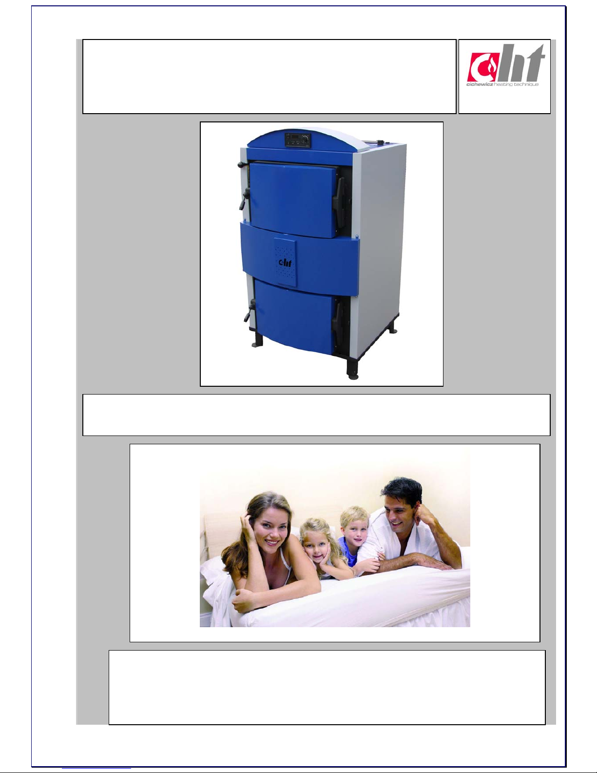
Sigma Holzgas 18-60k
W
Manual and Installation book
of boiler
CHT Heizkessel GmbH
Gartenfelder Strasse 29-37, 13599 Berlin, Tel.:+ 49 30 – 30 64 17 29 Fax: + 49 30 – 30 64 17 27
info@cht-heizkessel.de service@cht-heizkessel.de
wwwwww..cchhtt--hheeiizzkkeesssseell..ddee
IIHHRR PPAARRTTNNEERR FFÜÜRRUUMMWWEELLTTFFRREEUUNNDDLLIICCHHEESS HHEEIIZZEEN
N
Page 2

- 2 -
Manual and Installation book of boiler
Table of contents
1) Short description - 3 -
2) Technical data - 4 -
3) Fuel - 8 -
4) Using and Service - 8 -
5) Control -11-
6) System -14-
7) Parts -17-
8) Boiler installation systems -19-
www.cichewicz.com
With us heating makes economies!
Page 3

- 3 -
1) Short description
1.1) Gasification technology
The wood gas (ger. holzgas) comes in the process of gasifing of the wood. This
is the mixture of flammable gases: the oxide of carbon, hydrogen and methane,
and also incombustible -- nitrogen, the dioxide of carbon, water steam. The
composition of the gas depends on many factors as: from current temperature
in the hearth of the gas generator, the moisture of the loaded fuel and other.
The gasifing of solid fuels is technology counting above 200 years. On the
beginning XIX w. it was used so-called urban gas to the supply of cookers,
street lamp and to industrial aims. It was produced from the carbon then.
Generally -- the artificially formed gas from the gasifing of the solid fuel is called
the generator gas.
Technology this consists in the working on the solid fuel with series of thermochemical reactions, the flammable gas becomes in the result of them. Gasifing
just defines oneself this cycle of conversions. This process holds in the device
called gas-generator.
The type- matter of the wood gas can look as follows:
oxide of the carbon of CO 19%
hydrogen H2 18%
methane CH4 1,25%
dioxide of the carbon 12%
steam water H2O 2,50%
nitrogen N2 the rest
From these exchanged, only three first gases (coloured) are flammable.
Remaining do not burn and make up only unnecessary ballast, in the principle
they thin the gas and reduce its fuel value. From this regard it would be good to
remove them. However nitrogen from the wood gas can’t be removed (the basic
component of air, in which we gasify the wood), then can the water steam
relatively easily humid from the gas in the cooler. The content of the dioxide of
the carbon depends first of all from the temperature in the gas-generator (if
higher, the more CO and less CO2).
Page 4
- 4 -
1.2) Boiler
Boiler of type Westfalia Holzgas on first throw of the uninitiated eye does not
differ from the usual boiler on the wood. It has hearth, loading chamber and
ash-pan. The difference of working is however considerable -- it burns in it not
from the bottom to the top, but inversely. There is the loading chamber at the
top and the transformation of the wood follows in the wood gas in this chamber.
There is the nozzle below the chamber in which burning the wood gas mixed
previously with the air, which flows in from outside, follows. This element is
made from the heat-proof material. There is the ash-pan, in which burning down
the mixture of the wood gas with the air follows, under the nozzle. The boiler on
the wood gas from the back possesses accompanying flue gas to the chimney,
in this place the exchanger of warmth allowing to the heating of water from hot
flue gas is assembled.
The boilers of type Westfalia Holzgas are designed to heating up water in c. h.
installations which computational temperature of supply do not cross 85 °C.
They can be used in c. h. installations of flat, council or productive buildings,
which users require automatic feeding of fuel. Boilers can be assembled both in
modern and conventional heating installations.
Boiler steering has the possibility of pump regulation also loading storage tank.
Boiler of type Westfalia Holzgas utilizes wood in gasification process using
energy contained in wood with efficiency three times higher than traditional
boilers. Smoke and other emissions are cut to a very low level, making our
boilers nature friendly.
All works relating equipments of boiler room, way of installing boiler as
well as his exploitation must be realized compatible with valid norms and
regulations.
2) Technical data
Type Unit
Sigma 20
Sigma 30 Sigma 50
Power Range (Output):
kW
14,9-24
25-32 45-59
Fuel:
Wood (max. humidity 20%, max 50cm long)
Efficiency:
% > 89,90
Boiler Water Volume:
dm3
145 L
165 L 180 L
Max. Working Pressure:
bar 2
Min. Inlet Temp.
o
C 65
Max. Outlet temp.
o
C 85
Flue gases Temperature:
o
C >160
>160 >160
Noise:
dB 52 -65dB (A)
Recommended Chimney
Underpressure
Pa 20-25
CO2 emission
mg/m³ 4800 4820 4950
Page 5
- 5 -
Recommended Chimney's
Intersection
mm 160
160 180
Inlet/Outlet Diameter
“ 1,5
1,5 2
Bottom Outlet Diameter
“ 1/2
1/2 1/2
Weight:
kg
490
540 600
Power Consumption
W
82
82 90
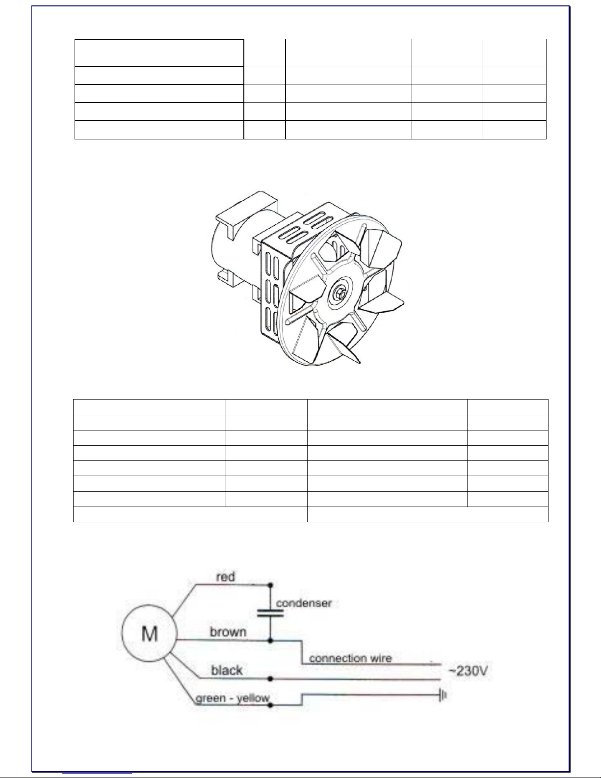
2.1) Outtake Fan WC170
2.1.1) Technical data
Power supply -230V, 50Hz Temp. of surroundings 0=40°C
Power consumption 82W Temp. of fumes do 350°C
Expense of air 38-UM /11 Loudness 65dB
Number of gears 1 Class of tightness IP44
Rotational speed 2400obr/min Class of isolation F
Condenser of the engine 3µF/450V Mass 2,2kg
Kind of the work continuous Supply wire 0,6m
External dimensions 186x174x174mm (lg. x wid. x h.)
2.1.2) Wiring diagram
Page 6

- 6 -
2.1.3) Placing in mounting hole
• Unscrew mounting plate
• Mount fan Wheel, plate and the engine together.
• Screw the plate with mounted fan into the mounting hole.
2.2) Structure of the boiler:
The structure of boiler was worked out on basics of long term researching with
idea about high thermal comfort, exploational and with care about ecology. The
boiler has the three pass structure in shape of vertical and horizontal convective
channels, making the surface of heat exchange. The combustion space is partly
tiled with fire-clay which attends as catalyst of combustion process. The body of
boiler is made from certified steels and welded in cover of argon. Westfalia
Holzgas is equipped in ceramic burner nozzle and ceramic deflectors.
2.3) Special features of Sigma Holzgas:
• Low exploitation cost
• Easy and simple service
• Long wood up to 50cm long
• Efficiency > 90 %
• Fuel loadings - once for 8 -12 hours
• Boiler power modulation 70-100 %
• Small ash quantity
• Electronic controller with
temperature sensor built in
• Nature friendly
• Produced of certify steel
Page 7

- 7 -
2.4) Dimensions of Sigma Holzgas:
mm Sigma 20 Sigma 30 Sigma 50
A
1510
1510
1510
B
725
825
825
C
840
840
960
D
1030
1030
1150
a
1,½"
1,½"
2 “
b
1,½"
1½"
2 “
c
½"
½"
½"
d
ø160
ø160
Ø200
2.5) Schema of Westfalia Holzgas:
Page 8

- 8 -
3) Fuel
9 Wood with humidity up to 25%
9 Chunks dimensions 30-50cm
The wood has to be dry! The efficiency of the boiler falls together with growing
moisture of the wood, settling tartly substances increases and the life of the
boiler drops. Power and proper functioning of the boiler are guaranteed near
maximum moisture the wood to 20%.
The energetic properties of the most popular species of the wood:
Wood type Thermal efficiency per 1 kg
kcal MJ kWh
Spruce 3900 16,25 4,5
Birch 3750 15,50 4,3
Oak 3600 15,10 4,2
Beech 3450 14,40 4,0
4) Using and Service
4.1) Assembly:
1. Fit the ceramic burner nozzle to the boiler via the rectangular hole located
inside of boiler.
2. Mount the ceramic deflectors into their place inside the lower chamber.
1.
2.
4.2) Burning
Put wood-chips or sawdust as base, then put inside little pieces of wood. At the
top put chunks of wood and set the fire with half-open ash doors and full open
shutter.
After firing close fire-doors and turn on work and adjust required temperature on
regulator.
The attemperation is done with help of the mechanical regulator (shutter) of
fireplace and with help of the electronic automatics mastering the work of fan.
Page 9
- 9 -
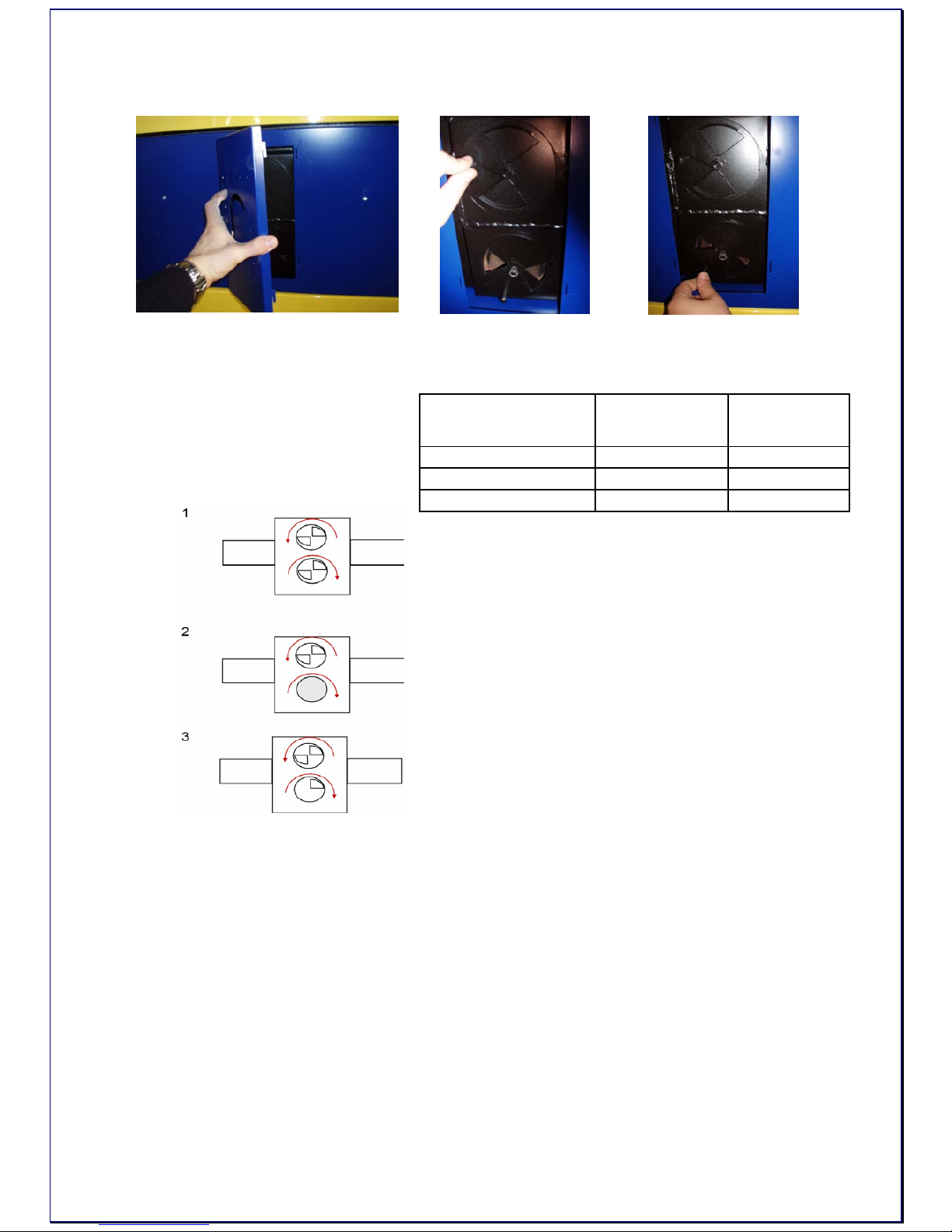
4.3) Setting air inlets
1.
2. 3.
Upper shutter is responsible for main air inlet.
Lower shutter is responsible for secondary air inlet.
The position of the shutter of
regulating opening in the
front plate of the casing
during exploitation:
4.4) Cleaning the burner.
When is cooled down completely it is ready for cleaning. Take the burner
nozzle of the assembly hole, remove the deflectors from the lower chamber.
The parts can now be worked with for cleaning.
To ensure best boiler operation, cleaning should be done frequently. This
guarantees the best fuel efficiency. The better the boiler is set up the
longer the intervals between cleaning.
Shutter position Power
Burning time
(in hours)
Max. open Nominal (full) 2
Open on 1/2 70% nominal 3
Closed Minimum 5
Page 10
- 10 -
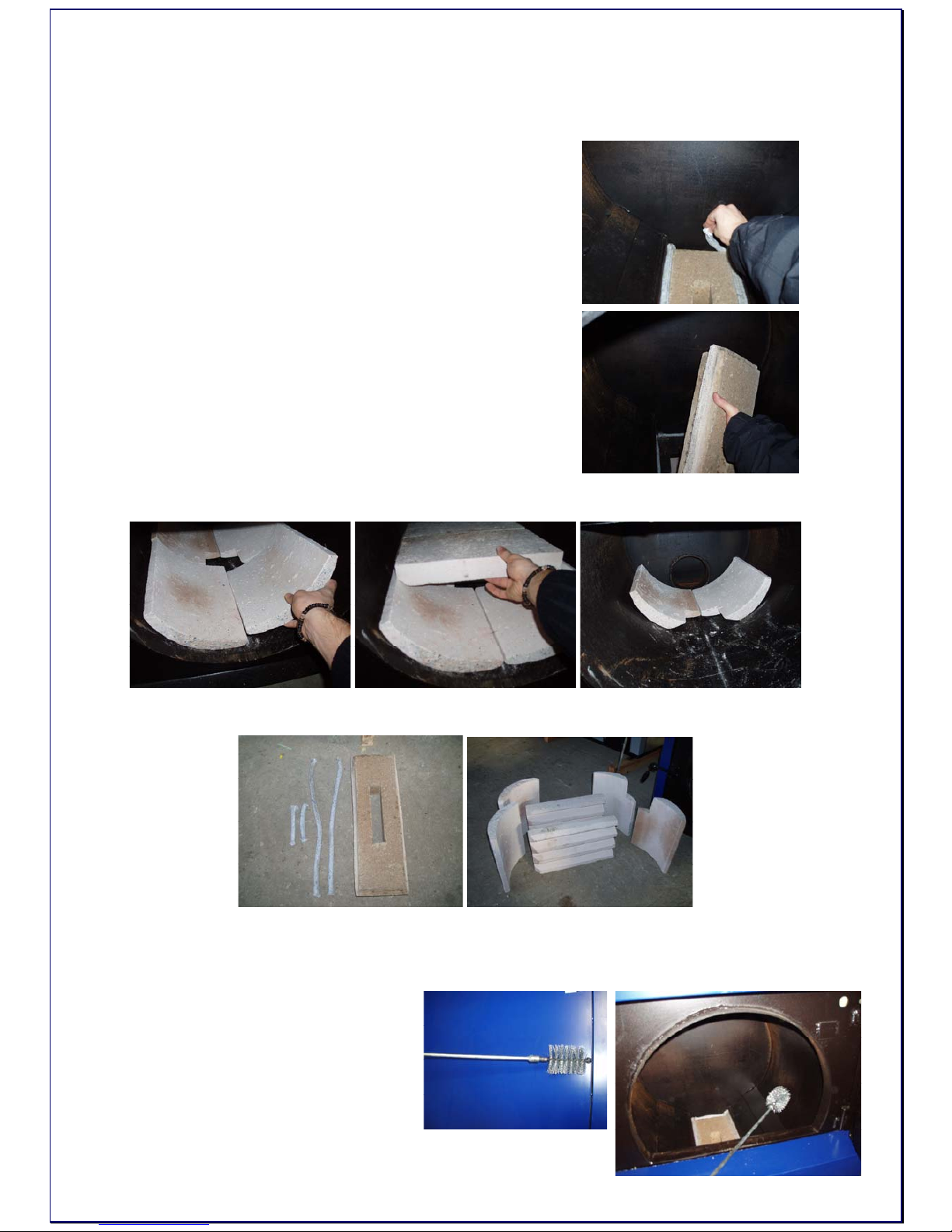
4.4.1) Clearing the deflectors and burner nozzle…
• Remove the ash and any cinders from the unit.
• Remove any wood left in the unit.
• Remove the tight rope.
• Take out the ceramic nozzle.
• Remove the ceramic deflectors from the lower chamber.
• Brush them gently with soft brush.
• Vacuum the left ash, do not touch the ceramic elements with vacuum head.
4.4.2) clearing the boiler…
The boiler should be emptied
from ash and all of the surfaces
should be brushed in order to
remove soot particles.
Page 11

- 11 -
Pay particular attention to ash in the exhaust deflector
and the flue pipe. The flue pipe does NOT clean itself.
You must do this yourself. An old vacuum cleaner is
the best method.
4.4.3) Clearing the exchanger…
• Upper cleanout
• Lower cleanout
4.4.4) Starting up after cleaning …
Reassemble the burner nozzle and fit deflectors into boiler. Load the boiler
partly and light it normally.
Page 12

- 12 -
5) Controller RK 2001W
5.1) Schematic diagram of work:
ventilator
"H"
speed maximum speed of ventilator "d"
"d"
speed near blowthroughs "E"
work work "P" work "P" work
ventilator
pause pause pause
"c" "c" "c"
T>Ts T<Ts
45 Ts Ts T<31oC
Phaze of
emblazing Automatic work Blanking
Ts -set temperature
6) Using and service
6.1) Fuel
9 pit-coal type 31 and 32 assortment nut O I and O II
9 pea coal Gk
9 coal-fines MI
9 substitutionaly wood (humidity up to 20%)
6.2) Control
6.2.1) Application
RK-2001W controller is a device designed for temperature control of solid fuel
fired boilers. The temperature of the boiler is kept on level set by the user by
controlling the speed of the blow-in fan. The controller constantly monitors the
temperature of water in the boiler, shows it on the display and controls the
central heating pump. To enable more precise temperature control of heated
rooms the controller has been equipped with an input for room thermostat
connection. The controller also enables controlling of the hot water tank pump.
In case of no fuel, the controller has an option to turn on gas or oil boiler
(additional option).
6.2.2) Connection
Before turning on the controller by master switch, connect controller, fan and
the central heating pump power leads to appropriate sockets in the rear of the
Page 13

- 13 -
controller. The temperature sensor should be placed in a measurement hole in
the boiler.
CAUTION! Before plugging in the controller check if the wiring system is properly grounded
and if the terminal screws of the output connector are properly screwed.
CAUTION! A fan and a central heating pump of maximum power of 450W can be connected
to the controller.
CAUTION! As additional option you can connect the UM-1 module to the controller that
allows controlling the additional boiler or the mixing valve and the hot water loading pump. It
is necessary to protect the power supply of these devices with suitable cut-outs.
Outputs of the controller that are not used may remain unconnected.
6.2.3) Operation
After turning the controller on all the elements of the display are lit for a while to
check if they are working properly. The controller, when power appears, returns
to its last state before turning off or power loss.
Front panel of the controller (Pic. 1) consists of:
1-Master switch
2-Display, indicating boiler temperature and parameters
3-Room thermostat indicator
4-Boiler thermostat knob
5-Central heating pump work indicator
6-STOP/choose parameters/erase alarms button
7-START/choose parameters button
8-Start programming /confirm parameters settings button
9-Hot water pump work indicator
Picture 1. Front panel of the RK-2001W controller
Basic operation of the controller is carried out by setting the desired
temperature with boiler thermostat knob, other functions are carried out
according to parameters programmed in service mode. The change in the boiler
temperature setting is shown on the display for a few seconds, e.g. [C 55] and
this value means the temperature of the water in the boiler which the controller
will be trying to achieve. You can also check this value by pressing OK button
Page 14

- 14 -
for a short time. After pressing START button the fan starts to work and the
control process begins. STOP button stops the fan for example to add fuel.
If the controller is not in user or service mode the display shows water
temperature in the boiler and the last character on the display defines the mode
which the controller is currently in:
for example: [50º-] - STOP mode
[50ºC] - WORK mode
[50ºc] - hold up of burning in WORK mode
[50ºU] – heating of hot water in SUMMER mode
[50°u] - hold up of burning in SUMMER mode
[50ºd] – total bacteria control – heating up of hot water
up to 75ºC.
6.2.4) Setting up the user parameters.
Holding OK button enters the user mode and allows reviewing and is indicated
by fast flashing of the room thermostat indicator. You can look through the
parameters with < and > arrow buttons. After choosing the desired parameter
you can switch to the change mode of the parameter by pressing OK button - it
is indicated by the value of the parameter flashing.
Change of the parameter is done by pressing - or + buttons. You can confirm
new settings by pressing OK button and after that the controller allows choosing
another parameter (with < > buttons). If you do not want to change the
parameter value with the < or > button choose [End] and press OK or wait for 1
minute – the controller will exit the user mode and will indicate the temperature
of the water in the boiler
CAUTION: If in the controller the hot water pump is turned off, in the user menu, after
pressing OK, you can only read the set temperature value of the boiler thermostat.
Table 1. Service parameters list
Display Parameter Min Max Step
Factory
default
C 40 Boiler desired temperature L 40 H 90 1˚C L 40
co C
Central heating pump work when “C” (pump
off when “-“)
- C C
cu u
“d” heating up – total bacteria control in hot
water tank
u d u
50˚ Water temperature in hot water tank
End Exit from user mode after pressing OK
(1) Boiler work temperature
The boiler set temperature [C 40] – is the temperature which the controller will
try to achieve in WORK mode.
It is set by direct turning of the knob and is indicated by a short display.
Page 15

- 15 -
(2) Central heating pump work [co C] – WINTER/SUMMER mode
– character “C” indicates that the central heating pump is working. In summer
time the heating can be turned off by choosing the value “-“ with the (-) button
which means turning off the central heating pump.
(3) Total bacteria control in the hot water tank – heating up - the
controller allows to manually launch the total bacteria control process in the
boiler. Choosing the “d” value with (+) button starts the process in which the
boiler is trying to achieve the temperature of 75˚C in the hot water tank. In order
to start the total bacteria control process the boiler should be in WORK mode
(this mode can be turned on by START button). E.g. [70˚d] will appear on the
display. After reaching 75˚C in the hot water tank the controller will return to its
state before choosing this option.
CAUTION: the total bacteria control function can switched on at night when the water from
the hot water tank is not used to prevent the users from burn injury.
(4) Water temperature readout in hot water tank [u50˚] – this
parameter shows the measured temperature value in the hot water tank.
(5) Exit from user mode – choosing the [End] on the display and
pressing OK button causes exit from the parameter setting. Exit from this mode
will also occur if no button is pressed for 1 minute.
6.2.5) Parameter setting – the service mode
Holding OK button for more than 3 seconds enters the service mode where you
can review and change the parameters. It is indicated by slow flashing of the
room thermostat indicator. You can look through parameters with < and > arrow
buttons. After choosing the desired parameter you can enter the parameter
setting mode which is indicated by this value flashing. The change of the value
will occur after pressing – or + button. Pressing OK button will confirm the
changes. After that the controller allows choosing another parameter with < >
buttons. If you do not want to change the parameter value with the < or > button
we choose [End] and pres OK or wait for 1 minute – the controller will exit the
service mode and will start indicating the temperature of the water in the boiler.
Table 2. Service parameters list
Display Parameter Min Max Step
Factory
defaults
∏100
Fan max work power or max power when
∏r 0-10
50 100 10% 100
∏r 1
automatic fan speed control and time of
fan start
--,0 10 1 1
∏n 5 Fan work time --,5 60 1s 5
∏u 6 Fan pause time 1 99 1min 6
P 40 Central heating pup launch temperature 30 70 1˚C 40
Page 16

- 16 -
Ph 2 Central heating pup launch hysteresis 1 10 1˚C 2
Pc 2
Pause time of central heating pump with
30 sec. work periods
--,1 99 1min 2
u 50 Tap hot water desired temperature 30 60 1˚C 50
uh 5 hot water heating hysteresis 1 9 1˚C 5
ur 0
No hot water-0, hot water priority-1, no
hot water priority-2, mixing pump-3
0 2 1 0
L 40 Minimum boiler temperature 30 65 1˚C 40
H 90 Maximum boiler temperature 80 90 1˚C 90
h 5 Boiler temperature hysteresis 1 10 1˚C 5
A 99 Boiler overheating temperature 90 99 1˚C 99
Fd60
Fuel shortage testing time with burning,
increase by 5˚C
1 99 1min 60
Fb30
Fuel shortage testing time in WORK
mode and burning out.
1 99 1min 30
Ar 0
Additional output: 0-FUEL, 1-ALARM, 2-
MIX
0 2 1 0
Prod
Return to factory defaults after pressing
OK
outP
Central heating pump output testing,
press OK - launch
outP out1
out∏ Fan output testing, press OK - launch out∏ out2
outr
Oil boiler launch output testing, press OK
– launch boiler
outr out3
outu
Hot water pump output testing, press OK
- launch
outr out4
End Exit the service mode after pressing OK
In the table above, the first column represents example display indications, in
the next columns there are: parameter description, minimum and maximum
values allowed to set, step of the parameter during the setup. The last column
shows factory defaults to which you can return by choosing [Prod] option.
(1) Fan work parameters
Fan power [Π100] - this value defines power of the fan. When "Πr" parameter is
set to "0-10" this is the maximum power of the fan which can be achieved
during automatic fan control.
Automatic fan speed control [Πr 1] - it is on, when this parameter is set to "0-10"
and causes automatic fan speed decrease when temperature of water in the
boiler reaches desired temperature. If this parameter is set to "-", the fan
automatic smooth speed control is disabled and the fan can work with power set
by "Π" parameter. Setting parameter value in range from 0 to 10 means time in
minutes of the smooth fan speed increase from 40% to value of "Π" - for smooth
boiler start.
Page 17

- 17 -
Fan work time [Πr 1] - time of turning the fan on for a while, to remove
accumulated gases. Setting the parameter to "--" turns this function off. This
function can be active in WORK mode.
Fan pause time [Nu 6] - time between fan work periods
(2) Central heating pump work parameters
Central heating pump launch temperature [P 40] – the value of temperature of
the water in the boiler which causes start of the central heating pump. Central
heating pump works independently from the control process and is launched
additionally in case of boiler overheat.
Central heating pump launch hysteresis [Ph 2]- this parameter defines what
value should the boiler water temperature decrease by, below the launch
temperature, so that the pump turns off.
Repeat launch time of the central heating pump [Pc 2] - in STOP mode or when
room thermostat circuit is open, the central heating pump is launched for 30
seconds to mix water in heating circulation. This parameter defines the repeat
time of launches of the pump.
Setting the parameter to "--" turns this function off.
(3) Preparation of domestic hot water
The controller has additional output allowing to control the hot water tank
loading pump by the UM (UM-1) module.
The hot water temperature [u50] – temperature value which will be kept in the
hot water tank. The heating hysteresis of the hot water heating [uh5] – value
which the temperature in the tank has to decrease by so that the hot water
pump turns on in order to heat up the water in the tank.
Parameter [ur 1] – the [ur 0] value indicates no sensor or hot water pump. The
sensor is not taken into account in testing failures, i.e. it can remain
unconnected and in the user parameter menu there is only the boiler thermostat
set temperature displayed.
[ur 1] value – hot water pump working with priority
[ur 2] value – hot water tank working without priority
[ur 3] value- means controlling of the returning water mixing pump in the boiler
with the launch temperature of [u 50] and hysteresis [uh 5].
(4) Setting of boiler work temperature range
Minimum boiler temperature [L 40] - minimum temperature which can be set
with the boiler thermostat knob.
Maximum boiler temperature [H 90] - maximum temperature which can be set
with the boiler thermostat knob.
Boiler temperature hysteresis [h 5] - this parameter defines what value should
temperature of water in the boiler decrease by, below temperature set with the
thermostat knob, so that the fan turns on.
(5) Protection against boiler overheating
Page 18

- 18 -
Boiler overheating temperature [A 99] - value, exceeding which causes
permanent turn off of the fan to prevent boiler overheating. After the
temperature increases above 80˚C the central heating pump is turned on to cool
down the boiler. Overheating mode is shown by indicating error [E 2] on the
display. It can be turned off by pressing STOP button, but only when
temperature decreases below this temperature.
Fan turn off also occurs in case of damage of the boiler temperature sensor
which is shown on the display with error [E 1].
STB - the controller has additional protection against overheating which is
independent from the processor. In case the temperature increases over 95°C,
the control process is turned off by turning the fan off and launching the central
heating pump. The fan and the pump are turned on to the control process again
when temperature drops below 89°C.
STB circuit enables more precise boiler work control and reduces overheating
possibility.
(6) No fuel
No-fuel testing time during fuel firing start [Fd60] - after switching to WORK
mode, if water temperature does not increase by 5°C in programmed time, the
control process will be turned off and the display will show the message:
[FUEL].
You can return to previous mode by pressing STOP button. No fuel testing time
during fuel firing is finished after the set temperature is achieved.
No-fuel testing time during work mode [Fb30] - in WORK mode, if temperature
of water in the boiler decreases below temperature set with the thermostat, by
hysteresis value, and does not increase by 5°C in the programmed time, the
control process will be turned off and the display will show the message:
[FUEL].
You can cancel the alarm by pressing STOP button.
(7) Additional output
Additional output [Ar 0] – the controller has been equipped with an output that
allows connection of the UM module. When the Ar parameter has the UM
module value “0” it may control the oil or gas boiler – if such boiler exists in the
heating circuit. After switching the controller with the main power switch the
additional boiler is turned off and it turns on again when there is no fuel in the
solid fuel boiler. This function is useful in heating systems where there is a solid
fuel boiler used to cut the heating costs. After erasing the “no fuel” alarm by
pressing STOP button the additional boiler is again turned off and the controller
works again. Setting parameter [Ar] to “1” allows controlling the additional alarm
signaling system with the UM module – which occurs on the controller.
When Ar parameter is set to “2” the UM module allows controlling the mixing
valve servo-motor in the central heating circuit depending on the room
thermostat input. In this case the work of central heating pump depends only on
the boiler temperature.
Page 19

- 19 -
(8) Factory defaults
The controller allows returning to standard settings set by the producer by
choosing [Prod] and pressing OK button. After activating this function, the
controller sets each parameter showed in the table.
(9) Output testing
To make checking the controller work easier, it is possible to test output circuits
which control the fan and the pump, and the additional boiler launching system.
This function is available in service mode, only if the control process is off, i.e.
the controller was in STOP mode before switching to service mode. By
choosing [outP] on the display and pressing OK button you can turn on the
central heating pump for a while, by choosing [outΠ] and pressing OK you can
turn on the fan and by choosing [outr] and pressing OK you can turn the
additional boiler on (if the additional module is connected). Choosing [outu]
allows testing the hot water pump output.
(10) Exiting service mode
By choosing [End] option on the display and pressing OK button you can exit
parameter setting mode.
The controller also exits service mode, when no buttons are pressed for 1
minute.
6.2.6) Additional functions
To improve comfort in heated rooms, the controller has been equipped with an
input that allows connecting any kind of room thermostat with contact output.
When temperature in the room is below desired temperature, the central
heating pump is turned on and the room thermostat indicator is lit.
It means that the boiler should keep temperature set by the room thermostat
knob. After reaching desired temperature in the room, the room thermostat
indicator turns off, the central heating pump is turned off and the boiler switches
to mode in which it keeps burning at minimum temperature.
CAUTION. In case of not having room thermostat in the system, the room thermostat input
contacts must be short-circuited.
6.2.7) Controller failures
The controller is constantly testing if its internal circuits and temperature sensor
are working correctly. After detection of fault, it stops the fan, turns on the
central heating pump and shows proper error message on the display. In case
of failure please turn off the controller, plug the central heating pump to the
power source, ensure appropriate fuel firing in the boiler and contact the
service.
Page 20

- 20 -
When [E 1] error appears on the display, it means fault in the boiler sensor
circuit or temperature below 0°C. [E 2] is displayed if boiler overheats. [E 3]
error means fault and overheating at the same time. Appearing of [E 1] error on
the display after erasing it by pressing STOP button, in spite of temperature
decreasing below 90°C, may mean permanent damage of boiler temperature
sensor (e.g. if the boiler has been overheated above 150°C). In case of
programming the sensor and central heating pump in the service mode the
controller tests the hot water sensor circuit. Appearing of fault [E8] means
damage or lack of hot water sensor.
Picture. 2. RK-2001W connection diagram
Page 21

- 21 -
Picture. 3 UM-1 module connection diagram
6.2.8) Controller removal
In case the removal is necessary proceed as follows:
- turn the master switch off
- disconnect the power of the boiler
- remove the controller from the slot in the boiler
- disconnect all connectors with leads from the controller
6.2.9) Specifications
Voltage: 230V ± 10%, 50Hz
Power consumption: <4VA
Temperature measurement range: 0–99°C ± 1°C
Boiler temperature adjustment range: 30–90°C ± 1°C
Programmed boiler overheating protection: 90 –99°C ± 1°C
Hardware boiler overheating protection (STB): >95°C ± 1°C
Central heating pump launch temperature: 30–70°C ± 1°C
Hot water temperature adjusting range: 30-60°C ± 1°C
Total fan-out: total max 2A/230V
Dimensions (HxWxD): 80x170x100 mm
6.2.10) Notes
Display Parameter User
∏100 Fan max work power or max power when ∏r 0-10
∏r 1 automatic fan speed control and time of fan start
∏n 5 Fan work time
∏u 6 Fan pause time
P 40 Central heating pup launch temperature
Ph 2 Central heating pup launch hysteresis
Pc 2
Pause time of central heating pump with 30 sec. work
periods
u 50 Tap hot water desired temperature
uh 5 hot water heating hysteresis
Page 22

- 22 -
ur 0
No hot water-0, hot water priority-1, no hot water priority-2,
mixing pump-3
L 40 Minimum boiler temperature
H 90 Maximum boiler temperature
h 5 Boiler temperature hysteresis
A 99 Boiler overheating temperature
Fd60 Fuel shortage testing time with burning, increase by 5˚C
Fb30
Fuel shortage testing time in WORK mode and burning
out.
Ar 0 Additional output: 0-FUEL, 1-ALARM, 2-MIX
7) System
7.1) Standards
• Heating System – during installation and operation of the boiler it is very
important to keep safe distance from the inflammable materials. The boiler is
allowed to work only in open type heating systems!
• Electrical installation – the boiler’s power supply is 230V/50Hz
• Chimney – It must be done with respect to current norms and regulations.
Due boiler gasses temperature 90-100 C it is obligatory to put the INOX or
other material tubes into the chimney. Required chimney draught is 0,1 – 0,2
mbar. Installation according to ADJ does entail some testing of the chimney,
which may be carried out by
a sweep
• Important sources of guidance installers: 98/37/EEG; 89/336/EEG;
73/23/EEG; EN 55014-1, 1993 /A1, 1997; EN 55014-1; EN 55014-2 C1
1998; EN 61000-3-2; EN 61000-4-2, -3-4-5-6-11, Level2; EN 50165; EN
50165 C1; EN 60335-1; EN 303-5; EN 12809; EN 13394
7.2) Localization of the boiler:
• Placing on flammable foundation.
• place the boiler on non-flammable and thermal insulating pad which should
protrude not less than 20 mm outside boiler’s dimensions;
• If the boiler is located in the basement it is required to place it on a base
raised not lower than 50 mm over floor’s level. The boiler and the fuel hopper
must stand vertically and can be levelled using the regulating screw in fuel
hopper’s leg.
• The (230V/50Hz) electric socket should be easy to access.
Page 23

- 23 -
7.3) Ventilation:
Accordantly with regulations each
boiler room has to have the ventilation
inlet and outlet in aim of assurance of
correct boilers work and users safety.
Lack of ventilation inlet or it’s stocking
is the most frequent cause of incorrect
work of boiler (the humidity, condense
water, impossibility of higher
temperature obtainment). Ventilation
outlet has instead in task of offtake
from room used air and harmful gases.
In boiler room with chimney with
natural draught it is not it allowed to
use mechanical ventilation.
7.3.1) Ventilation inlet
• The channel of ventilation inlet should have dimension of 50 % area of
chimney intersection, no fewer than 20 x 20 cm
• Channel should be 1m over floor
• In ventilation hole or in channel should be installed device to control of air
flow, however such to forbid decrease of intersection more than to 1/5
• Ventilation duct should be made from incombustible material
7.3.2) Ventilation outlet
• Channel should be made of brick and min. intersection of it should be 25% of
chimney intersection however not smaller than 14 x 14 cm
• Inlets can not have any closing it intersection devices
Page 24

- 24 -
• Spout should be under ceiling of room, led out on roof at least 1,5 m
• Ventilation duct should be made from incombustible material
7.4) Chimney connection:
• Flues should be made in accordance with current regulations.
• To reduce the resistances of flow of flue gases the connection with chimney
should be led in straight line and possible change of direction should be made
with gentle arcs.
• Boilers can be assembled into flues from brick with aligned internal welds
• Combustion duct should begin from floor line
• About 30cm. over floor should be to situated cleanout with tight lock
• Intersection should be
approximate to square with
regard on smaller
resistances of flue gases
flow
• The minimum intersection
of chimney amounts 20 x
20 cm
• The dams of brick between
duct and wall should not be
smaller than 12cm
• Chimney should be led out
over roof
• The location of chimney
outlet depends from the
degree of roof droop and
stages of the flammability.
The roof with angle of
droop to 12º - the chimneys
should stand over roof ridge
0.6m, roof with angle of
droop over 12º - the
chimneys should stand over
roof ridge in case of easily
flammable coverings 0,6m however in case of incombustible or difficultly
flammable covering, the outlet can occur 0,3m over roof ridge.
• Assembly of draught regulator is recommended, which in case of too big
underpressure in chimney opens and suck in the air from the boiler room and
does not pull it through boiler causing the temperature uncontrolled rise.
Interrupter this should be set on required value in dependence from power of
boiler
Page 25

- 25 -
8) Parts
Page 26

- 26 -
No. Part Description Serial Number
01. Left Side Casing F.h.b.l.01
02. Front Casing F.h.p.02
03. Top Casing (Hat) F.h.g.03
04. Door Casing Upper F.h.d.g.04
05. Door Casing Lower F.h.d.d.05
06. Steering Panel F.h.p.s.06
07. Right Side Casing F.h.b.p.07
010. Thermometer F.h.t.010
011. Thermostat F.h.t.011
012. Power Switch WA-12PS F.h.ł.012
013. STB F.h.STB.013
014. Fuse Nest FU max 4A F.h.g.b.014
020. Door Locking F.h.z.d.020
030. Ceramic Deflector Lower Part F.h.c.s.d.030
031. Ceramic Deflector Upper Part F.h.c.s.g.031
032. Ceramic Nozzle F.h.d.s.032
Page 27

- 27 -
9) Boiler installation systems:
¾ Open system
The bottom of the safety tank must be placed:
• In natural circulation systems or with pump on heating water H ≥ 0.3 [m]
over the highest point of the system.
• In systems with pump installed on return water: H ≤ 0.7Hp [m]
Page 28

- 28 -
Page 29

- 29 -
¾ Closed systems
Warning! – To collect boiler in closed system it is important to build in the boiler cooling loop
and then make a right connection:
Page 30

- 30 -
Page 31

- 31 -
Page 32

- 32 -
 Loading...