

Page 1

OPERATION MANUAL
User Software Version 3.1.1A
AMAX 200 is a trademark of Sigma-Amelung GmbH
April 2001 A6846
Page 2

SIGMA DIAGNOSTICS INSTRUMENT WARRANTY
Sigma-Aldrich Co., Inc. ("Sigma"), warrants that instruments it sells to be free from
defects in workmanship and materials during normal use by the original purchaser.
This Warranty shall continue for a period of one year from the date of invoice to the
original purchaser, or until title is transferred from the original purchaser, whichever
occurs first (the "Warranty Period").
If any defects occur during the Warranty Period, contact the Sigma Service Center
immediately, and be prepared to furnish pertinent details concerning the defect, the
model number, and the serial number.
Warranty service is provided 8:30 a.m. through 5:00 p.m., Monday through Friday,
except on Sigma observed holidays. Any service performed at other times, and all
service required to correct defects or malfunctions not covered by this Warranty, will
be billed on a time-and-material basis at Sigma's labor rates then in effect.
This Warranty does not cover defects or malfunctions which: (1) are not reported to
Sigma during the Warranty Period and within one week of occurrence; (2) result from
chemical decomposition or corrosion; (3) are described in the applicable Sigma
Operation Guide; (4) result from maintenance, repair, or modification performed
without Sigma's prior written authorization; or (5) result from misuse, abuse or
accident.
Sigma's liability for all matters arising from the supply, installation, use, repair, and
maintenance of the instrument, whether arising under this Warranty or otherwise,
shall be limited solely to the repair or (at Sigma's sole discretion) replacement of the
instrument or of components thereof. In no event shall Sigma be liable for injuries
sustained by third parties, incidental or consequential damages, or lost profits.
Replaced parts shall become the property of Sigma.
THE FOREGOING IS THE SOLE WARRANTY MADE BY SIGMA REGARDING THE
INSTRUMENT, AND SIGMA SPECIFICALLY DISCLAIMS ALL OTHER WARRANTIES,
EXPRESSED OR IMPLIED, INCLUDING THE WARRANTIES OF MERCHANTABILITY
AND OF FITNESS FOR A PARTICULAR PURPOSE.
2001 Sigma-Aldrich Co.
April 2001
Page 3

0
Table of Contents
1 INTRODUCTION .................................................................................................... 1-1
2 ORGANIZATION OF OPERATION MANUAL ............................................................. 2-1
2.1 PICTOGRAMS ..................................................................................................... 2-1
2.2 SECTION DESCRIPTION ..................................................................................... 2-2
3 SPECIFICATIONS.................................................................................................. 3-1
4 FEATURES............................................................................................................ 4-1
4.1 TEST PROGRAMMING ........................................................................................ 4-1
4.2 PROCESSING...................................................................................................... 4-1
4.3 DATA ARCHIVING............................................................................................... 4-1
4.4 MEASUREMENT MODES.................................................................................... 4-1
4.5 CALIBRATION ..................................................................................................... 4-2
4.6 SAMPLE HANDLING ........................................................................................... 4-2
4.7 REAGENT HANDLING......................................................................................... 4-2
4.8 PIPETTING SYSTEM............................................................................................ 4-3
4.9 TEMPERATURE CONTROL ................................................................................. 4-3
4.10 CUVETTE HANDLING ......................................................................................... 4-3
4.11 THROUGH-PUT................................................................................................... 4-3
4.12 QUALITY CONTROL ............................................................................................ 4-4
5 PHYSICAL DESCRIPTION ...................................................................................... 5-1
5.1 OVERVIEW ......................................................................................................... 5-1
5.2 CUVETTE STORAGE CHUTE .............................................................................. 5-1
5.3 INCUBATION RAIL AND PROBE WASH WELL ..................................................... 5-2
5.4 ROBOT ARM ....................................................................................................... 5-2
5.5 MEASURING WELLS........................................................................................... 5-3
5.6 REAGENT AND SAMPLE TRAY............................................................................ 5-3
5.7 SYRINGE ............................................................................................................ 5-4
5.8 BACK VIEW ........................................................................................................ 5-4
6 GENERAL SOFTWARE USE.................................................................................... 6-1
7 POWER ON ........................................................................................................... 7-1
7.1 AMAX 200 .......................................................................................................... 7-1
7.2 PERIPHERAL EQUIPMENT.................................................................................. 7-1
8 TRAFFIC SIGNAL LIGHTS AND STATUS INDICATOR BAR ...................................... 8-1
8.1 TRAFFIC LIGHTS ................................................................................................ 8-1
8.2 STATUS INDICATOR BAR ...................................................................................8-1
8.2.1 Operating Status .................................................................................... 8-1
8.2.2 Reagent Level Monitor ............................................................................ 8-1
8.2.3 Temperature Monitors ............................................................................ 8-2
8.2.4 Lamp Monitor......................................................................................... 8-2
8.2.5 Cuvette Box Monitor............................................................................... 8-2
8.2.6 Cuvette Tray Waste Monitor ................................................................... 8-2
April 2001 TOC 1
Page 4

0
Table of Contents
8.2.7 Fresh Water Input Monitor ..................................................................... 8-2
8.2.8 Waste Water Output Monitor .................................................................. 8-2
8.2.9 Test Group Selection .............................................................................. 8-2
8.2.10 Number of Files in Archive...................................................................... 8-2
8.2.11 File Format Date..................................................................................... 8-2
8.2.12 QC Status Monitor ................................................................................. 8-3
8.2.13 LIS Status Monitor .................................................................................8-3
9 OPERATION - QUICK-START ................................................................................. 9-1
9.1 ENTRY INTO QUICK-START ................................................................................ 9-1
9.2 INTRODUCTION TO QUICK-START DIALOG WINDOW........................................ 9-3
9.3 TEST GROUP SELECTION ..................................................................................9-3
9.4 ORDERING TESTS.............................................................................................. 9-4
9.5 REAGENT TRAY PREPARATION.......................................................................... 9-6
9.6 PRELIMINARY CHECKS ...................................................................................... 9-8
9.7 START PROCESSING .......................................................................................... 9-9
9.8 STOPPING OR ABORTING PROCESSING .......................................................... 9-10
9.9 VIEWING RESULTS .......................................................................................... 9-11
9.10 ADDING NEW SAMPLES................................................................................... 9-11
9.11 REPLENISHING REAGENTS.............................................................................. 9-13
9.12 REPEATING TESTS........................................................................................... 9-13
9.13 ADDING STAT SAMPLES .................................................................................. 9-14
9.13.1 Stat Sample Deletion ............................................................................ 9-15
9.14 PRINTING RESULTS ......................................................................................... 9-16
9.14.1 Routine samples ................................................................................... 9-17
9.14.2 Stat samples......................................................................................... 9-17
9.15 STARTING A NEW SAMPLE TRAY ..................................................................... 9-18
9.16 CHECKING QC RESULTS ................................................................................. 9-18
9.17 OPERATION AND MONITOR FUNCTIONS ......................................................... 9-18
9.17.1 Reagent Overview ................................................................................. 9-19
9.17.2 AMAX200 - Status................................................................................ 9-19
9.17.3 Prime.................................................................................................... 9-20
9.17.4 Wash .................................................................................................... 9-20
9.17.5 Test Groups.......................................................................................... 9-20
9.17.6 Check Reagent ..................................................................................... 9-20
9.17.7 Stop ..................................................................................................... 9-20
9.17.8 Abort .................................................................................................... 9-20
9.18 EXITING QUICK-START .................................................................................... 9-20
ABBREVIATED QUICK-START OPERATING PROCEDURE............................................ 9-22
10 OPERATION - NORMAL ........................................................................................10-1
10.1 REAGENT PREPARATION ................................................................................. 10-1
10.2 FRESH AND WASTE WATER CHECKS.............................................................. 10-3
10.3 CUVETTE PREPARATION.................................................................................. 10-4
10.4 FORMAT
10.5 SAMPLE IDENTIFICATION, POSITIONING AND TEST REQUISITIONING ........... 10-6
10.5.1 Keyboard Addition of New Patients ....................................................... 10-8
DATA FILES ....................................................................................... 10-6
April 2001 TOC 2
Page 5

0
Table of Contents
10.5.2 Keyboard Edit of Old Patients ............................................................. 10-10
10.5.3 Position Samples in Sample Tray........................................................ 10-11
10.6 START PROCESSING ...................................................................................... 10-11
10.6.1 Select Test Group ............................................................................... 10-12
10.6.2 Start................................................................................................... 10-12
10.7 PAUSE, STOP AND ABORT ............................................................................. 10-15
10.7.1 Pause ................................................................................................. 10-15
10.7.2 Stop ................................................................................................... 10-16
10.7.3 Abort .................................................................................................. 10-16
10.8 STAT TESTING................................................................................................ 10-16
10.8.1 Stat Requisitioning ............................................................................. 10-16
10.8.2 Viewing and Printing Stat Results....................................................... 10-17
10.8.3 Emptying Stat Positions and Transferring Sample to Archive.............. 10-17
10.9 OVERVIEW ..................................................................................................... 10-18
10.10 GRAPHIC MODE ............................................................................................. 10-18
10.11 REPEAT TESTING ........................................................................................... 10-18
10.12 PRINTOUT OF RESULTS ................................................................................. 10-19
10.13 EVALUATION OF QC RESULTS....................................................................... 10-20
10.14 PRINTOUT OF PATIENT REPORTS.................................................................. 10-21
10.15 ERRORS DURING PROCESSING: NON-FATAL ................................................ 10-21
10.16 ERRORS DURING PROCESSING: FATAL......................................................... 10-22
10.17 SHUTDOWN.................................................................................................... 10-23
11 MEASUREMENT PRINCIPLES ...............................................................................11-1
11.1 MECHANICAL MEASUREMENT (BALL METHOD) ............................................. 11-1
11.2 OPTICAL MEASUREMENT ................................................................................ 11-3
11.3 KINETIC OPTICAL MEASUREMENT (CHROMOGENIC)...................................... 11-5
12 MENUS OVERVIEW ..............................................................................................12-1
12.1 MAIN MENU...................................................................................................... 12-1
12.2 <ALT>-FUNCTION KEYS ................................................................................... 12-3
12.3 <CTRL-F1>-FUNCTION KEYS............................................................................ 12-5
12.4 DOS PARAMETERS........................................................................................... 12-5
12.5 MENUS OUTLINE ........................................................................................... 12-10
12.6 MENUS FLOWCHARTS ................................................................................... 12-14
13 OVERVIEW MENU ................................................................................................13-1
13.1 AMAX200.......................................................................................................... 13-1
13.2 REAGENT ......................................................................................................... 13-2
13.3 RESULTS .......................................................................................................... 13-3
13.4 SAMPLES.......................................................................................................... 13-4
14 SERVICE MENU ...................................................................................................14-1
14.1 PRIME .............................................................................................................. 14-1
14.2 WASH ............................................................................................................... 14-2
14.3 TRANSFER CUP................................................................................................ 14-2
April 2001 TOC 3
Page 6

0
Table of Contents
14.4 CHECK REAGENT ............................................................................................ 14-3
14.5 LAMP OFF/ON.................................................................................................. 14-3
14.6 CALIBRATE PHOTOMETER .............................................................................. 14-4
14.7 MOVE SYRINGE ............................................................................................... 14-4
14.8 CHECK VOLUMES ............................................................................................ 14-4
14.9 LOCK CHANNELS ............................................................................................. 14-4
14.10 MONITOR ......................................................................................................... 14-6
15 MEASURE MENU..................................................................................................15-1
15.1 TEST GROUPS .................................................................................................. 15-1
15.2 TRAYS .............................................................................................................. 15-2
15.2.1 Show .................................................................................................... 15-4
15.2.2 Delete ................................................................................................... 15-4
15.2.3 Load ..................................................................................................... 15-5
15.2.4 Load Auto............................................................................................. 15-6
15.3 ROBOT RIGHT .................................................................................................. 15-6
15.4 START............................................................................................................... 15-6
15.5 GRAPHIC ........................................................................................................ 15-12
15.6 PAUSE, STOP AND ABORT ............................................................................. 15-14
15.6.1 Pause ................................................................................................. 15-14
15.6.2 Stop ................................................................................................... 15-15
15.6.3 Abort .................................................................................................. 15-15
16 STAT MENU.........................................................................................................16-1
16.1 QUICK-START................................................................................................... 16-1
16.2 STAT POSITION 1 - 8 ........................................................................................ 16-1
16.2.1 Stat Requisitioning ............................................................................... 16-2
16.3 MONITORING AND PRINTING STAT RESULTS.................................................. 16-4
16.4 EMPTYING STAT POSITIONS AND TRANSFERRING DATA TO ARCHIVE........... 16-4
16.5 END.................................................................................................................. 16-5
17 PATIENTS MENU..................................................................................................17-1
17.1 NEW ................................................................................................................. 17-1
17.2 EDIT ................................................................................................................. 17-5
17.3 ADD.................................................................................................................. 17-7
17.4 REPEAT .......................................................................................................... 17-10
17.5 IMPORT .......................................................................................................... 17-12
17.6 EXPORT.......................................................................................................... 17-12
17.7 PATIENT LIST ................................................................................................. 17-13
17.8 RESULT LIST .................................................................................................. 17-13
17.9 RESULTS LIST ON-LINE ................................................................................. 17-15
17.10 REPORT.......................................................................................................... 17-15
18 SYSTEM MENU 1 .................................................................................................18-1
18.1 FORMAT DATA
18.2 SECURITY SYSTEMS: PASSWORD, SIGN ON, OR SET USER PIN ..................... 18-2
18.2.1 Password .............................................................................................. 18-3
FILES ....................................................................................... 18-1
April 2001 TOC 4
Page 7

0
Table of Contents
18.2.2 Sign ON................................................................................................ 18-4
18.2.3 Set User PIN ......................................................................................... 18-4
18.2.3.1 Add an Operator ................................................................... 18-5
18.2.3.2 Signing On ........................................................................... 18-6
18.2.3.3 Delete an Operator ............................................................... 18-7
18.2.3.4 To Edit PIN Information ........................................................ 18-7
18.2.3.5 Forgotten Password .............................................................. 18-8
18.3 DRIVE............................................................................................................... 18-8
18.4 OPTIONS .......................................................................................................... 18-9
18.5 HOST PARAMETERS....................................................................................... 18-11
18.6 LOCATION CODES ......................................................................................... 18-11
18.7 PANELS .......................................................................................................... 18-12
18.8 REPORT FORMAT ........................................................................................... 18-13
18.8.1 To Design the Report Format .............................................................. 18-13
18.8.2 Error Code Definition ......................................................................... 18-14
18.9 VERSION ........................................................................................................ 18-15
19 SYSTEM MENU 2 - PARAMETERS.........................................................................19-1
19.1 TEST GROUPS .................................................................................................. 19-2
19.1.1 To Define or Modify a Test Group ......................................................... 19-3
19.1.2 To Delete a Defined Test Group ............................................................ 19-5
19.2 TESTS............................................................................................................... 19-5
19.2.1 To Define a New Test ............................................................................19-6
19.2.1.1 Description ........................................................................... 19-7
19.2.1.2 Calibration ........................................................................... 19-7
19.2.1.3 Procedure ........................................................................... 19-10
19.2.1.4 Data reduction.................................................................... 19-11
19.2.1.5 Statistics ............................................................................ 19-12
19.2.2 Undo Test Parameter Definition .......................................................... 19-13
19.2.3 Exiting Test Parameter Definition ....................................................... 19-13
19.2.4 Saving Test Parameter Definition ........................................................ 19-13
19.2.5 Copy Test Parameter Definition from One Test to Another .................. 19-14
19.2.6 To Delete a Test from the Test List ...................................................... 19-14
19.2.7 Predilution Mode ................................................................................ 19-14
19.2.8 Derived Fibrinogen ............................................................................. 19-15
19.3 REAGENT LAYOUT ......................................................................................... 19-16
19.3.1 To Define or Modify a Reagent Layout ................................................. 19-17
19.3.2 To Delete a Previously Defined Layout ................................................ 19-18
19.4 REAGENT ....................................................................................................... 19-18
19.4.1 To Define a New Reagent or Modify a Previously Defined Reagent ....... 19-19
19.4.2 To Delete a Reagent ............................................................................ 19-20
19.5 LEVELS .......................................................................................................... 19-20
19.5.1 Diameter ............................................................................................ 19-21
19.5.2 Bottom Levels ..................................................................................... 19-22
19.5.3 Maximum Level .................................................................................. 19-23
19.5.4 Predilution Levels ............................................................................... 19-23
19.6 PUMP.............................................................................................................. 19-24
19.7 MEASURING MODE........................................................................................ 19-25
19.8 TEMPERATURE .............................................................................................. 19-28
April 2001 TOC 5
Page 8

0
Table of Contents
19.9 BACK UP ........................................................................................................ 19-29
19.10 RESTORE ....................................................................................................... 19-29
19.10.1 To Restore a Back Up File................................................................... 19-30
19.10.2 To Activate the Back Up Parameters ................................................... 19-31
20 QUALITY CONTROL MENU ...................................................................................20-1
20.1 QC SETUP ........................................................................................................ 20-4
20.1.1 Westgard Definitions ............................................................................ 20-4
20.1.1.1 Rule...................................................................................... 20-5
20.1.1.2 Enabled ................................................................................ 20-5
20.1.1.3 Alarm ................................................................................... 20-7
20.1.1.4 Option .................................................................................. 20-7
20.1.1.5 Flowchart of Information Transfer......................................... 20-9
20.1.2 Controls ............................................................................................. 20-10
20.1.2.1 Addition of a New Control ................................................... 20-10
20.1.2.2 To Modify a Previously Defined Control ............................... 20-13
20.1.2.3 To Delete a Control ............................................................. 20-15
20.1.2.4 Flowchart of Information Transfer....................................... 20-16
20.2 QC FILES........................................................................................................ 20-17
20.2.1 Create ................................................................................................ 20-17
20.2.1.1 On an Inactive Test............................................................. 20-18
20.2.1.2 On an Active Test ............................................................... 20-19
20.2.1.3 On an Undefined or Partially Defined Test .......................... 20-19
20.2.1.4 Reactivation of Previously Closed Files................................ 20-19
20.2.2 List..................................................................................................... 20-21
20.2.3 Export ................................................................................................ 20-22
20.2.4 Backup............................................................................................... 20-22
20.2.5 Restore ............................................................................................... 20-23
20.2.6 Delete ................................................................................................. 20-24
20.2.7 Flowchart of Information Transfer. ..................................................... 20-25
20.3 QC CHARTS.................................................................................................... 20-26
20.3.1 Thumbnail Charts .............................................................................. 20-27
20.3.2 Zoom Chart ........................................................................................ 20-29
20.3.2.1 Introduction ....................................................................... 20-29
20.3.2.2 Commands ......................................................................... 20-30
20.3.2.3 Mean30/Mean .................................................................... 20-33
20.3.2.4 Comment on a Data Point................................................... 20-33
20.3.2.5 Omit a Data Point. .............................................................. 20-34
20.3.2.6 Append a File...................................................................... 20-35
20.3.2.7 Change the Target Value..................................................... 20-36
20.3.2.8 New File.............................................................................. 20-36
20.3.3 Z-Score Distribution Chart ................................................................. 20-37
20.3.4 Print QC Report .................................................................................. 20-37
20.4 RULE SENSITIVITY SETTINGS........................................................................ 20-39
20.5 VIOLATION EXAMPLES .................................................................................. 20-41
20.6 DISTRIBUTION ............................................................................................... 20-45
20.6.1 Distribution Chart and Report ............................................................ 20-45
20.7 CALIBRATION CURVES .................................................................................. 20-46
20.8 REFERENCES................................................................................................. 20-47
April 2001 TOC 6
Page 9

0
Table of Contents
21 END MENU...........................................................................................................21-1
21.1 REMOVE STAT SAMPLES ................................................................................. 21-1
21.2 HOST STATUS .................................................................................................. 21-1
21.3 PRINTER BUFFER ............................................................................................ 21-2
21.4 DOS SCREEN ................................................................................................... 21-2
22 CALIBRATION......................................................................................................21-1
22.1 AUTOMATIC DILUTION..................................................................................... 22-1
22.2 MANUAL DILUTION .......................................................................................... 22-5
22.3 SINGLE-POINT CALIBRATION........................................................................... 22-6
22.4 DERIVED FIBRINOGEN .................................................................................... 22-6
23 MAINTENANCE ....................................................................................................23-1
23.1 SERVICE OUTLINE ........................................................................................... 23-1
23.2 DAILY MAINTENANCE ...................................................................................... 23-3
23.2.1 Clean Probe Exterior............................................................................. 23-3
23.2.2 Fresh Water Check ............................................................................... 23-3
23.2.3 Waste Fluid Disposal............................................................................ 23-4
23.2.4 System Wash........................................................................................ 23-4
23.2.5 Hydraulic System Leak Check .............................................................. 23-5
23.2.6 Used Cuvette Disposal .......................................................................... 23-5
23.2.7 Cuvette Cassette Disposal Area Check .................................................. 23-5
23.2.8 General Housekeeping.......................................................................... 23-6
23.3 WEEKLY MAINTENANCE .................................................................................. 23-7
23.3.1 Hydraulic System Cleaning................................................................... 23-7
23.3.2 Dust Filter Cleaning ............................................................................. 23-8
23.3.3 Incubation Rail and Wash/Rinse Well Cleaning .................................... 23-8
23.3.3 Coolant Level Check ............................................................................. 23-9
23.4 MONTHLY MAINTENANCE.............................................................................. 23-10
23.4.1 Syringe Cleaning ................................................................................ 23-10
23.4.2 Cleaning of Photometric Measuring Wells ........................................... 23-10
23.5 MISCELLANEOUS UNSCHEDULED MAINTENANCE ....................................... 23-11
23.5.1 Photometer Calibration....................................................................... 23-11
23.5.2 Volume Check .................................................................................... 23-13
23.6 REPLACEMENT PROCEDURES ...................................................................... 23-14
23.6.1 Photometer Lamp ............................................................................... 23-14
23.6.2 Syringe/Plunger Assembly.................................................................. 23-15
23.6.3 Syringe Plunger Tip and O-Ring.......................................................... 23-15
23.6.4 Tubing................................................................................................ 23-16
24 QUALITY ASSURANCE..........................................................................................24-1
24.1 PATIENT SAMPLE ............................................................................................. 24-1
24.2 REAGENTS ....................................................................................................... 24-1
24.3 INSTRUMENT MECHANICS ..............................................................................24-1
24.4 TEST PARAMETERS ......................................................................................... 24-2
24.5 MEASUREMENT ANALYSIS ..............................................................................24-2
24.6 RESULTS .......................................................................................................... 24-2
April 2001 TOC 7
Page 10

0
Table of Contents
25 TROUBLESHOOTING............................................................................................25-1
25.1 NON-FATAL ERRORS........................................................................................ 25-1
25.2 FATAL ERRORS ................................................................................................ 25-1
25.3 GENERAL TROUBLESHOOTING ....................................................................... 25-3
26 INSTALLATION ....................................................................................................26-1
26.1 INSTALLATION.................................................................................................. 26-1
26.2 LOCATION REQUIREMENTS............................................................................. 26-1
26.3 ELECTRICAL REQUIREMENTS AND PRECAUTIONS......................................... 26-1
26.4 REMOVAL OF SHIPPING SAFETY CLAMPS ....................................................... 26-2
26.5 FRESH WATER AND DRAIN CONNECTIONS..................................................... 26-2
26.6 POWER ON ....................................................................................................... 26-2
27 INTERFACE SPECIFICATIONS ..............................................................................27-1
27.1 MODES............................................................................................................. 27-1
27.2 BI-DIRECTIONAL INTERFACE DESCRIPTION ................................................... 27-1
27.3 PROTOCOL ....................................................................................................... 27-3
27.3.1 MASTER to SLAVE ............................................................................... 27-3
27.3.2 SLAVE to MASTER ............................................................................... 27-4
27.4 COMMAND CHARACTERS AND SYMBOLS ....................................................... 27-5
27.5 TIMEOUT.......................................................................................................... 27-5
27.6 REPEAT AFTER <NACK>................................................................................... 27-5
27.7 EXAMPLES (AMAX AS MASTER) ....................................................................... 27-6
27.8 EXAMPLE OF HEADER AND TEST ORDER..................................................... 27-10
April 2001 TOC 8
Page 11

1
Introduction
1 INTRODUCTION
1 INTRODUCTION .................................................................................................... 1-1
April 2001 1-0
Page 12

Page 13

1
Introduction
The AMAX 200 is an automated random access multi-purpose analyzer. The
AMAX 200 may be used as a coagulation analyzer for the detection of fibrin formation
utilizing either mechanical principles (ball method) or photo-optical principles.
Such tests include prothrombin time (PT), activated partial thromboplastin time
(APTT), fibrinogen concentration, thrombin time (TT), functional factor assays and
other clotting tests ending with fibrin formation. In addition, the AMAX 200 may be
used for chromogenic kinetic enzyme analysis (405nm). Such tests include
antithrombin (AT), protein C, protein S, antiplasmin, heparin, plasminogen, PAI-1, tPA
and other assays utilizing an indicator molecule detected at 405 nm. Measurement
may be qualitative or quantitative. When used in conjunction with appropriate
reagents, the sample may be plasma, serum or whole blood.
The AMAX 200 is PC controlled. To provide optimum performance and maximum
versatility, the operating parameters for each test are individually programmed.
Patient samples are identified by the commander PC and registered in a patient file.
With the use of the on-board barcode reader, patient identification is positive. Patient
demographic and result information is archived for subsequent retrieval. Both the
results and the correlated calculations are stored in the patient file. Information may
be transferred to and from a host computer through a bi-directional interface.
The sample storage area is cooled to approximately 15°C. which minimizes sample
deterioration and prevents spontaneous cold activation that may occur at colder
temperatures. Sampling may be from primary tubes or secondary transfer tubes.
Sample and reagent are added using a temperature-controlled probe. All incubation
times are programmable. The programmed volume of reagent is added at the
programmed time. With addition of the start reagent, either the elapsed time or
absorbency is measured.
The measured results are calculated into concentration or activity units with the use of
stored calibration curves.
On-line, real-time statistical analysis and evaluation of QC data assists in determining
if results are valid and patient results may be reported.
Waste disposal is automatic with minimal operator contact with potentially
biohazardous materials.
April 2001 1-1
Page 14

3
Specifications
1 SPECIFICATIONS
3 SPECIFICATIONS.................................................................................................. 3-1
April 2001 3-0
Page 15

Page 16

Specifications
AMAX 200 Dimensions
•
Height 25 inches (64 cm)
•
Width 32¾ inches (83 cm)
•
Depth 28¾ inches (73 cm)
Keyboard
•
Height ca. 1¼ inches (3 cm)
•
Width ca. 11 inches (28 cm)
•
Depth ca. 5¼ inches (13 cm)
Printer
•
Height ca. 10 inches (25 cm)
•
Width ca. 13¾ inches (34 cm)
•
Depth ca. 22 inches (55 cm)
Optional Base Unit Dimensions
•
Height 28¼ inches (71 cm)
•
Width 32¾ inches (82 cm)
•
Depth 27¾ inches (69 cm)
3
Weight
•
AMAX 200 286 pounds (130 kg)
•
Base Unit 165 pounds (75 kg)
Electrical
•
Voltage 90 - 132 VAC; 60 Hz
180 - 265 VAC; 50 Hz
•
Power Consumption 600 VA
•
Fuse Requirements 5A (t) 6.3x32 and 10A (t) 6.3x32
Room Temperature Requirements
•
Maximum Operating Temperature 90°F (32°C)
•
Compensation Required 2047 BT
April 2001 3-1
Page 17

4
Features
4 FEATURES............................................................................................................ 4-1
4.1 TEST PROGRAMMING ........................................................................................ 4-1
4.2 PROCESSING...................................................................................................... 4-1
4.3 DATA ARCHIVING............................................................................................... 4-1
4.4 MEASUREMENT MODES.................................................................................... 4-1
4.5 CALIBRATION ..................................................................................................... 4-2
4.6 SAMPLE HANDLING ........................................................................................... 4-2
4.7 REAGENT HANDLING ......................................................................................... 4-2
4.8 PIPETTING SYSTEM............................................................................................ 4-3
4.9 TEMPERATURE CONTROL ................................................................................. 4-3
4.10 CUVETTE HANDLING ......................................................................................... 4-3
4.11 THROUGH-PUT................................................................................................... 4-3
4.12 QUALITY CONTROL ............................................................................................ 4-4
April 2001 4-0
Page 18

Page 19

Features
4.1 Test Programming
•
Up to 32 tests may be programmed at one time
•
All sample and reagent volumes, incubation times, reagent addition times and
measurement times are programmable to provide maximum flexibility and optimum
test performance
4.2 Processing
•
Random access; multi-tasking
•
Process mechanical, optical and chromogenic tests simultaneously
•
Choice of two operating modes: normal and quick-start
•
Normal mode: up to 12 tests processed simultaneously using multiple screens to
provide for maximum operating flexibility
•
Quick start: up to 8 tests processed simultaneously with all operations performed
using one screen
4.3 Data Archiving
4
•
Up to 1,020 patients may be archived on commander PC hard drive
•
Optional storage of patient data archive on floppy discs
•
Patient demographic, value results and correlating calculation information is stored
in the archive. With graphic mode on, graphic representation of each reaction is
also stored in the archive
4.4 Measurement Modes
•
Photo-optical/chromogenic: 4 channels, 405 nm
•
Mechanical: 4 channels
•
Minimum reaction volume, mechanical: 75 µL
•
Minimum reaction volume, optical/chromogenic: 150 µL
•
Maximum reaction volume, all modes: 600 µL
•
Programmable mechanical impulse mode minimizes break-up of fragile fibrin clots
•
Simultaneous mechanical, photo-optical and chromogenic analysis
•
Real-time graphic reaction display for optical and chromogenic kinetic analyses
•
28 clotting measuring modes; 16 chromogenic measuring modes
•
Monitor available to observe the performance of individual measuring wells
•
Channel locking to remove selected measuring wells from service facilitates
troubleshooting and minimizes downtime by enabling continuation of processing in
the event of isolated channel component failure
April 2001 4-1
Page 20

4
Features
4.5 Calibration
•
1 to 8 calibration curve points
•
Automatic dilution at any desired dilution from 1:1 to approximately 1:14,000
•
Calculation and display of correlation coefficient for each curve
•
Dilution of calibration reference material either automatically or with previously
prepared dilutions
•
Choice of 10 curve calculation types
•
Graphic display of calibration curve for easy visual evaluation
•
Ability to recalculate curve data using multiple curve calculation types
4.6 Sample Handling
Cooled (15 ± 3°C) sample storage area with 60 position continuous-addition sample
•
tray
•
Up to 8 samples at one time may be processed as Stats
•
Up to 17 sample trays with up to 60 samples each may be prepared for processing
(1,020 samples) in a file format period
•
5 µL minimum sample volume
•
Choice of duplicate or single sampling for each test within a test group
•
Automatic sample predilution at any desired dilution from 1:1 to 1:100
•
Automatic dilution to either a higher or lower dilution when result exceeds
calibration curve limits
•
Automatic repeat at a programmable extended time interval for samples failing to
clot within the specified measurement time
•
Integrated bar code scanner provides capability for positive patient ID
•
Optional off-line bar code scanner provides capability for alternative patient ID
entry
4.7 Reagent Handling
•
Cooled (15 ± 3°C) reagent storage area with 24 position reagent tray; 16 used only
for reagent storage, 8 used for either reagent storage or as Stat sample positions
•
3 stir-bar positions
•
Up to 50 reagents may be defined
•
Operator notification of expired reagents
•
Up to 5 reagents may be programmed for each test
•
Up to 12 different reagent tray layouts may be programmed
•
Minimum reagent levels required prior to and during processing are programmable;
reagent levels are continuously monitored and may be refilled with no processing
interruption; audible alarm notifies operator of low reagent volume condition
•
Reagent container dead volume dependent on container size and on the
programmed bottom level sense
•
No tubing; direct probe reagent aspiration results in no reagent waste and minimal
daily maintenance
4-2 April 2001
Page 21
Features
4.8 Pipetting System
•
Samples and reagents are transferred to the reaction cuvette with a temperaturecontrolled probe (37 ± 0.5°C)
•
Liquid level sensor for both sample and reagent
•
Bottom level sensing programmable to any depth for both sample and reagent
positions
•
Cleaning of probe programmable for each reagent
4.9 Temperature Control
•
Reagent/Sample trays: 15 ± 3°C
•
Incubation rail: 37 ± 0.5°C
•
Probe: 37 ± 0.5°C
•
Optical measuring wells: 37 ± 0.5°C
•
Mechanical measuring wells: 37 ± 0.5°C
•
Continuous monitoring and display of temperatures
•
Temperature warning and stop limits are programmable. Audible alarm and
flashing display when temperature is out of the warning limit range. Program stop
if temperature condition is out of the stop limit range and is not corrected within a
specified time period
4
4.10 Cuvette Handling
•
450 on-board cuvette capacity with continuous refill without processing
interruption
•
Automatic disposal of cuvettes through measuring wells at completion of
measurement timing
•
Maximum cuvette utilization
4.11 Through-Put
•
Variable; dependent on test combination, programming and sample conditions
•
Typical through-put:
Tests/Hour Single Duplicate
PT-Mechanical (Pipette mode 0) 180 180 90
PT-Mechanical (Pipette mode 2) 240 240 120
PT-Optical (Pipette mode 0) 190 190 95
PT-Optical, Derived Fibrinogen 120 120 60
APTT-Mechanical or Optical 110 110 55
Fibrinogen 115 115 57
AT 80 80 40
Factor Assay 120 120 60
PT-Mechanical/APTT 120 60 30
PT-Mechanical/APTT/AT 90 30 15
Patients/Hour Patients/Hour
April 2001 4-3
Page 22

4
Features
4.12 Quality Control
•
Unlimited number of control files
•
1000 result positions per control level file
•
Levey-Jennings-like graphic representation of up to 1000 results on each control
for each test programmed
•
Zoom chart feature to view specific details including historical rule violations and
operator-entered comments; each data point has associated result, date measured,
time measured, operator logged on when result processed, Westgard rule
evaluation and audit trail for point omission information available
•
Any data point may be omitted after user ID and comment are entered
•
Optional user ID system with four authorization levels available
•
Multiple breakdown (last 30 results, all results, all results up to cursor position) of
statistical data
•
Laboratory defined operator alert conditions with QC error
•
Real-time performance monitor
•
Westgard Rules or other laboratory definable result criteria evaluation
•
Optional processing stop in event of a QC error
•
QC File backup and restore functions available
4-4 April 2001
Page 23

5
Physical Description
1 PH
YSICAL DESCRIPTION
2 PH
YSICAL DESCRIPTION
5 PHYSICAL DESCRIPTION ...................................................................................... 5-1
5.1 OVERVIEW ......................................................................................................... 5-1
5.2 CUVETTE STORAGE CHUTE .............................................................................. 5-1
5.3 INCUBATION RAIL AND PROBE WASH WELL ..................................................... 5-2
5.4 ROBOT ARM ....................................................................................................... 5-2
5.5 MEASURING WELLS........................................................................................... 5-3
5.6 REAGENT AND SAMPLE TRAY............................................................................ 5-3
5.7 SYRINGE ............................................................................................................ 5-4
5.8 BACK VIEW ........................................................................................................ 5-4
April 2001 5-0
Page 24

Page 25
Physical Description
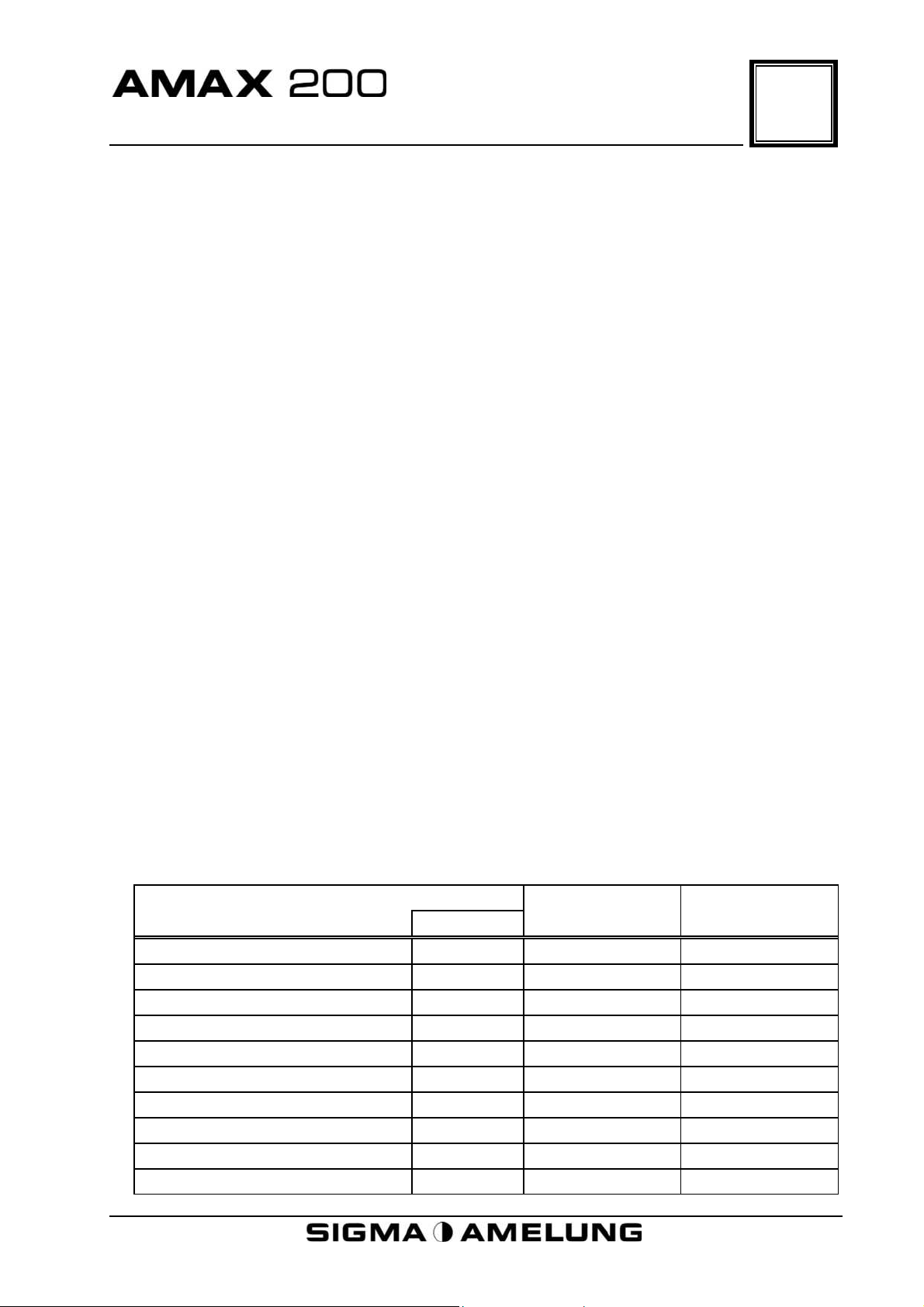
5.1 Overview
1. Power Switch
2. Cuvette Storage Chute
3. Empty Cuvette Box Disposal
Area
4. Cuvette Waste Drawer
5. Reagent/Sample Tray Area
6. Robot Arm
7. Measuring Wells
8. Syringe
9. Status Signal Lamps
10. Monitor
11. Floppy Drive
5
12. Keyboard Tray
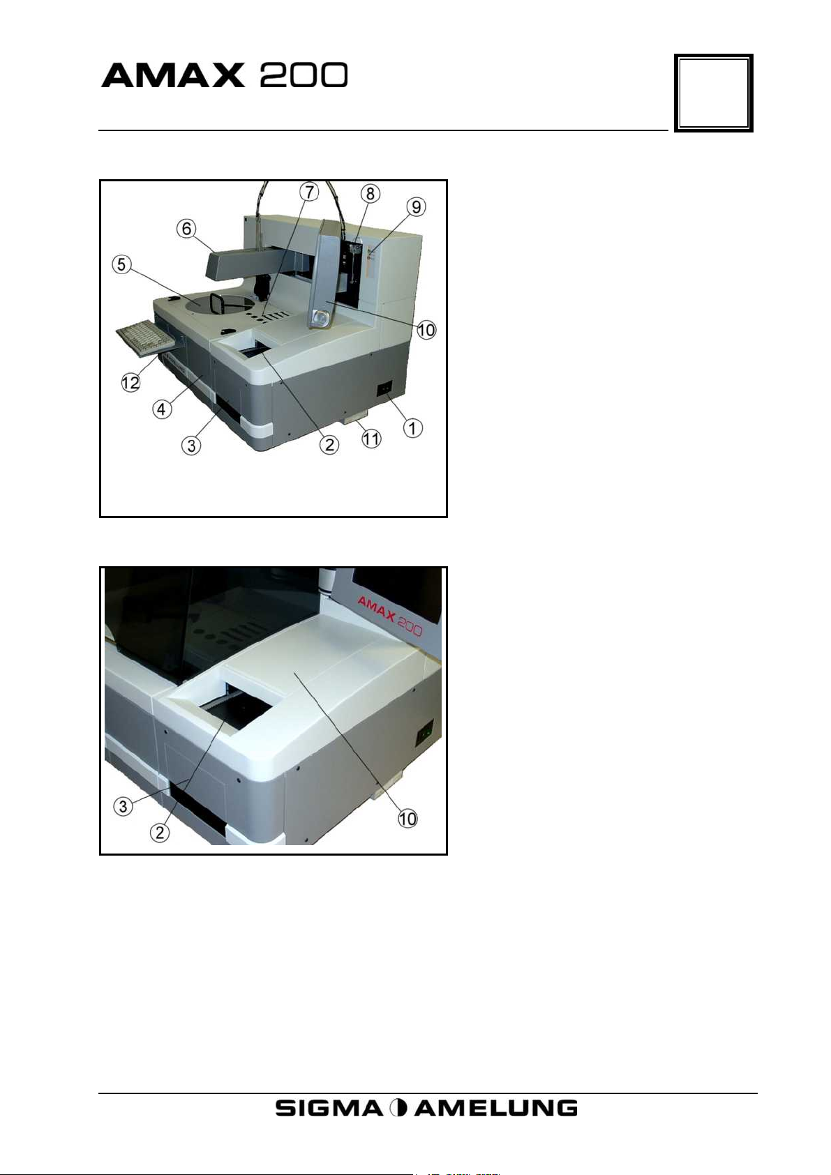
5.2 Cuvette Storage Chute
2. Cuvette Chute, Loading Area For
New Cuvette Boxes
3. Empty Cuvette Boxes Disposal
Area
10. Cuvette Storage Chute Cover
April 2001 5-1
Page 26
5
Physical Description
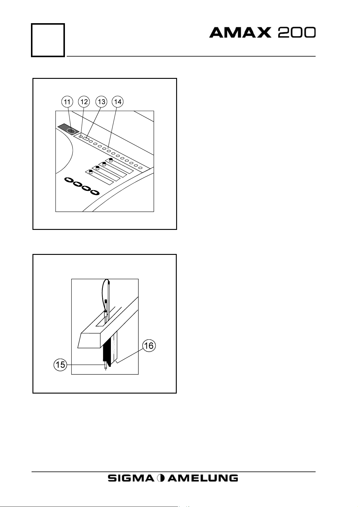
5.3 Incubation Rail and Probe Wash Well
11. Container For Decontaminating
Solution
12. Probe Wash Well
13. Cuvette Transfer Position
14. Incubation Rail
5.4 Robot Arm
15. Temperature Controlled Probe
16. Cuvette Removal and Transfer
Mechanism
5-2 April 2001
Page 27
Physical Description
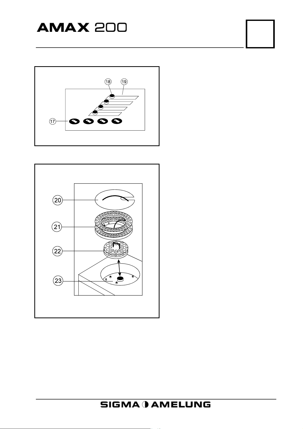
5.5 Measuring Wells
5.6 Reagent and Sample Tray
5
17. Mechanical Measuring Wells
18. Cover Knob
19. Optical Measuring Wells
20. Cover
21. Sample Tray
22. Reagent Tray
23. Reagent/Sample Tray Well
April 2001 5-3
Page 28
5
Physical Description
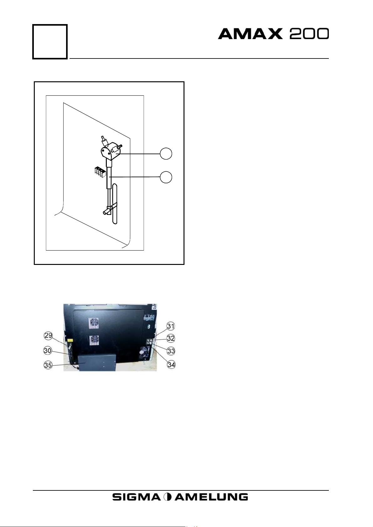
5.7 Syringe
27
28
27. Valve
28. Syringe
5.8 Back View
29. PC Computer Socket
30. Power Socket
31. Fresh Water Level Sensor
Connector
32. Fresh Water Inlet Connector
33. Drain Outlet
34. Drain Level Sensor Connector
35. Internal PC
5-4 April 2001
Page 29

6
General Software Use
1 GENERAL SOFTWARE USE
6 GENERAL SOFTWARE USE.................................................................................... 6-1
April 2001 6-0
Page 30

Page 31

6
General Software Use
Unless otherwise specified, all user interface instructions and screen descriptions are
for AMAX software version 3.1.1A.
Instructions are presented using conventional software terms. “Type” means use the
keyboard to type in information. “Press” means press the specified key.
Execution actions are in bold and enclosed by < >. For example: When the operator
action required is to press the “Enter” Key, the action is represented as <Enter>.
If simultaneous depression of two keys is required, both keys will be indicated,
separated by a hyphen and enclosed by < >. For example: When the operator action
required is to press both the “Alt” Key and the “F2” Key, the action is represented as
<Alt-F2>.
Menus and submenus may be selected either by moving the <Cursor Keys> to the
desired menu/submenu followed by <Enter> or by pressing the color-coded letter of
the desired menu/submenu.
Move through dialog windows using the <Cursor Keys>. Make appropriate entries
utilizing either the keyboard or <Function Keys>. Help information for the dialog
window appears in the first line at the top of the screen. Active <Function Keys> for
that dialog window are indicated in the second line on the screen. How to exit from the
screen is displayed at the bottom of the dialog window.
Most dialog windows are presented as examples. Because the display of the various
windows is conditional on events, the exact sequencing of window displays may vary.
When the AMAX 200
inactivity. Press any key to return to the menu screen.
When the AMAX 200 is in “Busy” mode, an audible alarm will alert the operator to
situations that may require operator attention or to instrument malfunctions. Pressing
<Alt-F2> will silence the alarm.
is in “Ready” mode, a screen saver will activate after 5 minutes of
April 2001 6-1
Page 32

7
Power On
1 POWER ON
7 POWER ON ........................................................................................................... 7-1
7.1 AMAX 200 .......................................................................................................... 7-1
7.2 PERIPHERAL EQUIPMENT.................................................................................. 7-1
April 2001 7-0
Page 33

Page 34

7
Power On
7.1 AMAX 200
Power up the AMAX 200 by pressing the power supply switch from OFF to ON.
The switch is located on the lower back corner of the right side of the instrument.
The switch lights up green when power to the instrument is ON.
Do not switch OFF and ON rapidly. Wait 10–15
seconds after switching OFF before switching ON.
At power ON, the robot arm and the Reagent/Sample Trays (if positioned in the well)
move to the home position.
7.2 Peripheral Equipment
Two minutes after the AMAX 200 is powered ON, the PC components may be turned
ON. Switch printer, monitor and PC to ON.
WARNING!
The Main Menu of the AMAX 200 Operating Program will be displayed on the monitor
screen.
The PC and other peripheral equipment are considered to be an integral part of the
AMAX 200 and are dedicated to the operation of the system. The addition of any other
software programs (including screen savers) will seriously compromise the operation
and reliability of the AMAX 200.
WARNING!
Under no circumstances should any software other than
that authorized by Sigma-Amelung GmbH be installed
n the PC provided for operation of the AMAX 200.o
April 2001 7-1
Page 35

8
Traffic Signal Lights and Status Indicator Bar
1 US INDICATOR BAR
8. TRAFFIC SIGNAL LIGHTS AND STATUS INDICATOR BAR ...................................... 8-1
8.1 TRAFFIC LIGHTS ................................................................................................ 8-1
8.2 STATUS INDICATOR BAR ...................................................................................8-1
8.2.1 Operating Status .................................................................................... 8-1
8.2.2 Reagent Level Monitor ............................................................................ 8-1
8.2.3 Temperature Monitors ............................................................................ 8-2
8.2.4 Lamp Monitor......................................................................................... 8-2
8.2.5 Cuvette Box Monitor............................................................................... 8-2
8.2.6 Cuvette Tray Waste Monitor ................................................................... 8-2
8.2.7 Fresh Water Input Monitor ..................................................................... 8-2
8.2.8 Waste Water Output Monitor .................................................................. 8-2
8.2.9 Test Group Selection .............................................................................. 8-2
8.2.10 Number of Files in Archive...................................................................... 8-2
8.2.11 File Format Date..................................................................................... 8-2
8.2.12 QC Status Monitor ................................................................................. 8-3
8.2.13 LIS Status Monitor ................................................................................. 8-3
April 2001 8-0
Page 36

Page 37

8
Traffic Signal Lights and Status Indicator Bar
8.1 Traffic Lights
The signal lights are located on the upper right-hand corner of the front panel. The
status of the instrument may be observed from a distance by the following light
patterns:
1. No lighted areas indicate that the instrument is not processing and there are no
error area conditions.
2. Green area lit (Go light) indicates that the instrument is processing and there are
no error conditions.
3. Yellow area lit (Caution light) indicates that a condition requiring operator attention
exists. Condition at this point in time is not of sufficient gravity to stop processing.
Error condition will be displayed in a red field in the status area at the bottom of
the main menu.
4. Red area lit (Stop light) indicates that a serious unrecoverable error condition has
been detected. If processing, the run has been aborted. Follow directions displayed
in red at the top of the monitor screen.
5. Sequential flashing lights indicate that a serious error has occurred and the
instrument is undergoing automatic reset. Processing has stopped.
8.2 Status Indicator Bar
The status of all the critical operating modules is indicated in the “Status Bar” located
across the bottom of the Main Menu screen.
Reagent
Operating
Status
8.2.1 Operating Status
The left-hand side of the status bar at the bottom of the Main Menu screen displays
the operating status. It provides information as to whether the instrument is ready
to operate, is busy, or is waiting for an incubation to end. A black "Ready" is
displayed when no error conditions exist and the instrument is available to begin
processing. A red "Ready" indicates an error condition that needs operator attention
before beginning processing. During processing, the area will be green when there
are no error conditions on the sample currently being processed. The area will be
red when an error condition on the sample has occurred (i.e., duplicate, no sample,
timeout exceeded). The area will revert to green when measuring on the next
sample begins. When "Wait" is displayed, a sample is incubating prior to
measurement and no other tasks are imminent.
Levels
Reagent
Tray
ºC
Incubation
Rail ºC
Probe
ºC
Lamp Status Cuvette
Boxes
Optical
Meas.
ºC
Mech.
Meas.
ºC
Cuvette
Waste
Fresh
Water
Waste
Water
Current Test
Group
Number
of files
in
Archive
File
format
date
QC
Status
LIS
Status
8.2.2 Reagent Level Monitor
Red with flashing “Chk. Reagent” when reagent is below the programmed minimum
volume level. Area is empty when reagent levels are OK or have not been checked.
April 2001 8-1
Page 38

8
Traffic Signal Lights and Status Indicator Bar
8.2.3 Temperature Monitors
The temperatures of five critical areas are constantly monitored. These areas are (1)
Sample/Reagent area; (2) Incubation Rail; (3) Probe; (4) Optical Measuring Wells;
and, (5) Mechanical Measuring Wells. The temperature area will be red with
flashing numbers if the indicated temperature is outside of set limits. When
temperatures are within the set limits, the numbers are displayed in black.
8.2.4 Lamp Monitor
The lamp status monitor indicates whether the lamp is ON or OFF. It will be a red
“Wait” until the operational voltage output is reached. It will be a red field with
flashing “Lamp error” if the lamp is burned out or otherwise inoperable. The area
will be blank if all optical wells have been locked out.
8.2.5 Cuvette Box Monitor
A minimum of two cuvette boxes must always be present. When at least two boxes
are in the cuvette chute, the field will display black “OK”. The field will be red with
flashing “Cups” if fewer than two boxes are present.
8.2.6 Cuvette Tray Waste Monitor
The cuvette boxes fall to the bottom of the chute area and are either removed from
the chute manually or allowed to fall through a disposal opening into a waste
container. When there are no more than two empty boxes in the chute area in front
of the disposal opening, the monitor area will display as black “OK”. When there are
more than two boxes in the disposal area, the area will display as red with flashing
yellow “Tray waste”.
8.2.7 Fresh Water Input Monitor
When the input supply water level is adequate, the area will display as black “OK”.
When input water is below sensor level, the area will display as red with flashing
“Empty”.
8.2.8 Waste Water Output Monitor
When waste water in the output water container is below sensor level, the area will
display as black “OK”. When the waste water is above the sensor level, the area will
display as red with flashing “Full”.
8.2.9 Test Group Selection
Displays the currently selected test group. If no group is currently selected, the
area is blank.
8.2.10 Number of Files in Archive
Displays the number of files stored in the patient archive since the last file format.
8.2.11 File Format Date
Displays the date the patient archive was formatted.
8-2 April 2001
Page 39

Traffic Signal Lights and Status Indicator Bar
8.2.12 QC Status Monitor
When QC evaluation rules are enabled, the results of samples identified as QC
material are monitored as the results are completed. When no rule violation has
occurred, the area will display black “QcOK”. When a rule has been violated, the
area displays as red with flashing “QcErr”.
8.2.13 LIS Status Monitor
Displays the status of the current transmission to the host interface.
Display Description
Lis – black on white Last transmission successful; all OK
Lis – black on red Error in last transmission
Exp – yellow flashing on white Data is being transmitted to host
Exp – yellow flashing on red
Imp – yellow flashing on white Data is being received from host
Imp – yellow flashing on red Data is being received after a previous error
Data is being transmitted after previous
error
8
April 2001 8-3
Page 40

9
Operation – Quick-Start
1 OPERATION – QUICK-START
9 OPERATION - QUICK-START ................................................................................. 9-1
9.1 ENTRY INTO QUICK-START ................................................................................ 9-1
9.2 INTRODUCTION TO QUICK-START DIALOG WINDOW........................................ 9-3
9.3 TEST GROUP SELECTION .................................................................................. 9-3
9.4 ORDERING TESTS.............................................................................................. 9-4
9.5 REAGENT TRAY PREPARATION .......................................................................... 9-6
9.6 PRELIMINARY CHECKS ...................................................................................... 9-8
9.7 START PROCESSING .......................................................................................... 9-9
9.8 STOPPING OR ABORTING PROCESSING .......................................................... 9-10
9.9 VIEWING RESULTS .......................................................................................... 9-11
9.10 ADDING NEW SAMPLES ................................................................................... 9-11
9.11 REPLENISHING REAGENTS.............................................................................. 9-13
9.12 REPEATING TESTS ........................................................................................... 9-13
9.13 ADDING STAT SAMPLES .................................................................................. 9-14
9.13.1 Stat Sample Deletion ............................................................................ 9-15
9.14 PRINTING RESULTS ......................................................................................... 9-16
9.14.1 Routine Samples .................................................................................. 9-17
9.14.2 Stat Samples ........................................................................................ 9-17
9.15 STARTING A NEW SAMPLE TRAY ..................................................................... 9-18
9.16 CHECKING QC RESULTS ................................................................................. 9-18
9.17 OPERATION AND MONITOR FUNCTIONS ......................................................... 9-18
9.17.1 Reagent Overview ................................................................................. 9-19
9.17.2 AMAX 200 - Status ............................................................................... 9-19
9.17.3 Prime.................................................................................................... 9-20
9.17.4 Wash .................................................................................................... 9-20
9.17.5 Test Groups.......................................................................................... 9-20
9.17.6 Check Reagent ..................................................................................... 9-20
9.17.7 Stop ..................................................................................................... 9-20
9.17.8 Abort .................................................................................................... 9-20
9.18 EXITING QUICK-START .................................................................................... 9-20
ABBREVIATED QUICK-START OPERATING PROCEDURE............................................ 9-22
April 2001 9-0
Page 41

Page 42

9
Operation – Quick-Start
The following are prerequisites to operation in the Quick-Start mode:
•
System is powered up (Section 7).
•
All operating parameters have been defined (Sections 18 and 19).
A Quick-Start summary is provided at the end of this section.
9.1 Entry into Quick-Start
“Quick-Start” is an alternative operation mode that has been designed to minimize
operator interaction with multiple screens. Because it is so easy to use this operation
mode, operators with minimal training may utilize it very effectively. It is also very
useful in laboratories with continuous sample arrival.
In order to make operation of the AMAX 200 as simple as possible, the number of
commands needed to operate have been reduced to an absolute minimum. All
operations are carried out using a single dialog window.
Because a single dialog window is used, there are certain limitations when compared
to the normal operating mode.
•
All samples are identified by an ID code. Entry of full patient demographic
information or location is not possible. Either a unique number or name may be
used as the ID code.
•
The integral barcode reader is not used. The barcode number may be entered either
manually with the keyboard or with an off-line barcode reader.
•
The number of tests that may be requested per sample is limited to 8.
•
A maximum of 60 samples may be processed per processing period.
•
The “Quick-Start” dialog window cannot be exited during processing.
Whenever the AMAX 200 is activated, the main menu screen appears:
Overview Service Measure Stat Patients System Q.C. End
Operating
Status
Reagent
Levels
Reagent
Tray
°C
Incubation
Rail °C
Probe
°C
Lamp Status
Optical
Meas.
°C
Mech.
Meas.
°C
Cuvette
Boxes
Cuvette
Waste
Fresh
Water
Waste
Water
Current Test Group QC
Status
Number
of files in
Archive
File
format
date
LIS
Status
The available menus are displayed across the top of the screen.
April 2001 9-1
Page 43

9
Operation – Quick-Start
There are two ways to access the Quick-Start operating mode:
1. Using the <arrow> keys, move the cursor to Stat and press <Enter>; or,
2. Press < t >
The “Stat menu” will open.
Overview Service Measure Stat Patients System Q.C. End
Operating
Status
Reagent
Levels
Reagent
Tray
°C
Incubation
Rail °C
Probe
°C
Quick-Start
Quick-Start
1. Position
2. Position
3. Position
4. Position
Lamp Status
Optical
Meas.
°C
Mech.
Meas.
°C
If there are no Stat positions assigned in
current Test Group reagent layout, only
Quick-Start is displayed.
If Stat positions are assigned in current
Test Group Reagent Layout, the window also
shows the number of assigned Stat
positions (1-8).
Cuvette
Boxes
Cuvette
Waste
Fresh
Water
Waste
Water
Current Test Group
Number
of files in
Archive
File
format
date
QC
Status
LIS
Status
The Stat menu will open with the cursor on “Quick-Start”.
9-2 April 2001
Page 44

9
Operation – Quick-Start
With the cursor on Quick-Start, press <Enter>.
If a Test Group is active, the Quick-Start dialog window opens immediately. If no Test
Group is currently selected, the “Select Test Group” dialog window appears. See
Section 9.3, Step 3 for instructions on selecting a Test Group. If any reagents in the
currently selected Test Group are expired, the “Expired reagent” dialog window will
appear. Replace expired reagent(s) as necessary. After replacing reagents, respond to
“Start run?” with <y><Enter>.
“/”,”*”,”-”,”+”,”R”,<Space> selects, <Shift>-<Enter>, ↓,↑, copies
F1:Display F2:Print F3:Service F8:Panel F9:Process F10:Delete
P. Identification PT-O
1
2
3
4
Sec
PTT-M
Sec
FIB-O
mg/dL
AT%A
5
6
9.2 Introduction to Quick-Start Dialog Window
The keystrokes and function keys used to carry out tasks within Quick-Start are
displayed in the two rows at the top of the screen. The listing serves as a reminder
during operation. The use of these keys will be covered later when it's time to use
them.
The numbers in the “P” column indicate the sample tray position number. The sample
tray is numbered from 1 to 60. Samples are positioned consecutively in the tray. Up to
sixty samples may be processed within any processing period.
The “Identification” column is used to identify the samples. Samples may be identified
by either number or name (20-character limit). Anything that provides a unique entry
is acceptable. The instrument will not accept duplication of any entered sequence. The
entry must be unique.
The next 8 columns are used for test ordering. The short name codes listed at the top
of each column are the tests that are available and may be ordered during the
processing period. All processing on the AMAX 200 is done in “Test Groups”. A Test
Group in Quick-Start may be composed of any 8 currently programmed tests. The
tests listed at the top of the column are those of the currently active test group.
9.3 Test Group Selection
The first consideration is to assure that the tests you want to run are available. Since
all testing on the AMAX 200 is done by Test Groups, the first task is to pick a Test
Group that contains the tests you want to run. In Quick-Start, a Test Group may be
comprised of from 1 to 8 currently programmed tests. Test Groups cannot be defined
within Quick-Start. The Test Group selection must be from those previously defined.
April 2001 9-3
Page 45

9
Operation – Quick-Start
The currently active Test Group is always displayed in the bottom righthand corner of the Main Menu Screen and is visible even
when the Quick-Start dialog window is open. The Test
Group for any given processing period may be selected from
within Quick-Start.
The <Function Keys> at the top of the screen are used to
perform certain tasks.
To select a Test Group:
1. Press <F3> (Service).
2. The Quick-Start Service submenu will open.
19.1
Reagent overview
CS200 – Status
Prime
Wash
Test Groups
Check Reagent
Stop
Abort
3. Move the cursor to <Test groups> and confirm selection with <Enter>.
The “Test Groups” selection window opens.
Group
Routine
PT
PTT
PT/PTT
Quick-Start
FIB
TT
Infac
Exfac
The Service submenu offers a variety of utility operations
and monitoring functions. The complete use of this
submenu is covered later.
The window displays the code name for all defined test
groups. The designation may be anything that adequately
describes the test group. Test groups are not defined
within Quick-Start.
It is common to have a “Quick-Start” test group defined
that contains all tests (up to 8) that are routinely run in
the Quick-Start operation mode.
It is useful to have a listing of the tests included in each
test group posted near the instrument.
4. Move the cursor to the desired <Test Group> and confirm with <Enter>.
5. Press <Esc> to return to the Quick-Start dialog window.
6. The tests included in the selected test group are displayed at the top of the test
ordering columns. Any one or all of these displayed tests may be run in the current
processing sequence. If a test group is selected that contains more than 8 tests,
only the first 8 tests in that group will be available.
9.4 Ordering Tests
1. Patient samples: Type a unique sample identification in the “Identification”
column. Type in the appropriate numbers or characters. Press <Enter>. An off-line
barcode reader (optional equipment) may be used to enter the ID. If the number or
name entered is not unique, there will be an audible beep and a message that says
“multiple!!!” is displayed. It means that this sample ID is already in the patient
archive and cannot be used again in this file-formatting period.
9-4 April 2001
Page 46

Operation – Quick-Start
QC samples are entered using a QC code which represents the ID Code defined for
that control in combination with a 2-digit identifier sequence code. The 2-digit
sequence identifier may be any combination of the following:
A. 00 through 99
B. A0 through Z9
C. 0A through 9Z
D. AA through ZZ
The 2-digit sequence identifier is prefaced by the ID Code defined for that specific
control. For example: One of the defined controls is ACCUCLOT Normal and its ID
Code has been defined as ACN. Valid ID entries to signal the AMAX 200 that this is
a QC sample are: ACN00 through ACN99; ACNA0 through ACNZ9; ACN0A through
ACN9Z; and, ACNAA through ACNZZ.
The same QC number cannot be used repeatedly. For example, the first AccuClot
Normal after file formatting is called ACN00; the second ACN01; the third ACN02.
If the QC code entered is not unique, there will be an audible beep and a message
that says “multiple!!!” is displayed. It means that this QC ID code is already in the
data archive and cannot be used again in this file-formatting period.
9
2. The cursor will move into the test ordering area.
3. The <arrow> keys are one way to move from place to place. Another, and usually
more efficient way, is to use the numerical keypad. The numerical keypad is used
to facilitate rapid test selection and movement through the dialog window.
Order test(s) on the first sample as described below.
The <Num Lock> indicator light must
be illuminated.
< / > moves the cursor one column to
the left.
< – > moves the cursor one column to
the right.
<
> orders the test assigned to that
*
column and advances the cursor
to the next column to the right.
< + > Orders test assigned to column.
<F8> (Function Key). Brings up a
listing of defined panels. Type in
the <Panel #><Enter>.
4. When a test is ordered, ***** fills the selected test column for that sample. If a test
is ordered accidentally or if you change your mind and want to delete an already
ordered test, the <Space> key on the letter keyboard deletes an ordered test. Move
the cursor over the test you wish to remove and press the <Space> key.
5. New entries are displayed in yellow.
April 2001 9-5
Page 47

9
Operation – Quick-Start
6. Once tests have been ordered on a sample, there are several options for proceeding.
Which option to use is dependent on the next sample.
<Enter> (either on character keyboard or on numeric keypad) advances
the cursor to the next sample identification position and
numerically increments the previous ID by 1.
<↓> advances cursor to the next sample position without numerical
increment ready for entry of the next sample ID.
<Shift-Enter> copies the ordered tests on the current sample to the next
or <Shift-
7. Continue as above until the appropriate identification and tests have been
completed for other samples that are ready for processing. More information on
processing options is presented below. Note that if Quick-Start is exited prior to
starting processing, all previously entered new IDs and test requests will be
cancelled.
↓
> sample. If the sample has not been identified and a numeric ID
was used for the previous sample, the next consecutive number
will be automatically assigned as the ID-code.
9.5 Reagent Tray Preparation
1. Each Test Group has an assigned Reagent Layout. A Reagent Layout designates the
position of each reagent used by all the tests within the test group. The levels for all
reagents used by the group are automatically checked prior to beginning
processing.
Reagent Layouts cannot be defined or modified from
within Quick-Start.
To find out what reagents are required, access the Service submenu by pressing
<F3>.
Reagent overview
CS200 – Status
Prime
Wash
Test Groups
Check Reagent
Stop
Abort
The “Reagent overview” window will open.
The submenu will open with the cursor on “Reagent
overview”.
Confirm the selection by pressing <Enter>.
If for any reason the cursor is not on “Reagent overview”,
use the <↑> or <↓> keys to position it correctly. Confirm with
<Enter>.
19.3
9-6 April 2001
Page 48

Operation – Quick-Start
[Reagent overview]
9
Cleaner
1. Ring (outer) 2. Ring (middle) 3. Ring (inner)
1 Stat 9 ThromboMAX 17
2 Stat 10 18 APTT
3 Stat 11 19 Calcium Chloride
4 Stat 12 20
5 13 21 Thrombin (FIB)
6 14 22
7 15 Imidazole Buffer 23 AT Thrombin/Hep
8 16 24 AT Substrate
The exact position in the reagent tray of
all reagents required is displayed. The
position number corresponds to a
numbered position in the Reagent Tray.
The green bar indicates the last measured
amount of each reagent. The red bar
1
169
17
24
indicates the amount of reagent that has
been used. If the red bar is flashing, the
reagent is below the minimum level
3
2319
required prior to processing.
If the test group has been changed or if no
processing has been performed using this
reagent layout, all levels will be indicated
in red regardless of the actual amount of
reagent present.
20
4
22
21
1312
5
Although not required prior to processing,
the reagent level monitor may be updated
whenever the instrument is not
processing. If levels are not monitored
prior to processing, it is the responsibility
of the Operator to assure that sufficient
Ring 1 Ring 2 Ring 3 Stir Bar
quantities of reagent(s) are present. If a
new test group is selected or if this is the
first processing period for the test group, when processing is started, the first task
that the instrument performs is a check of the reagent levels. If the level of any
reagent is below the minimum amount required prior to starting processing, no
tests using that reagent will be processed. Tests with missing reagents will no
longer be displayed at the top of the test ordering columns. If the cleaner is below
the minimum required level, no tests will be processed.
82
151810
7
1411
6
Position
2. Reagent levels may be checked either manually or automatically.
To manually check levels: Remove the Plexiglas cover over the reagent tray storage
area. Remove any lids present on all reagents assigned in the reagent layout. Check
the reagent levels by examining each reagent container for an adequate fill.
April 2001 9-7
Page 49

9
Operation – Quick-Start
Replenish reagent(s) as necessary. Reagent containers are considered disposable
although they may be reused several times with appropriate periodic cleaning. Be
sure to retrieve any stir bars prior to disposal. Replace cover when finished. The
notch in the cover must be aligned with the matching alignment guide. There is a
magnet on the lid that when in contact with the sensor on the lip of the storage
area will assure that the cover is in the correct position.
To automatically check levels: If still in the Reagent Overview window, press <Esc>
to close the window. The underlying Service submenu will be revealed. If
performing this task from the Quick-Start dialog window, press <F3> to gain access
to the Service submenu.
Reagent overview
CS200 – Status
Prime
Wash
Test Groups
Check Reagent
Stop
Abort
Assure that the lids have been removed from all assigned reagents. Reposition
cover. The cover must be on and properly positioned.
Move the cursor to “Check reagent”. Confirm selection by pressing <Enter>.
The robot probe will go to each assigned reagent position, check the level and
update the monitor. The cleaner level is checked first and if the cleaner level is
insufficient, no other levels will be checked. Return to the “Reagent Overview”
window to observe the level check.
Replenish reagents as necessary.
9.6 Preliminary Checks
1. Check that the supply of fresh degassed water is adequate and that the waste
container is not full. Replenish or empty as necessary.
Optimum performance of the instrument is dependent on having a bubble free
hydraulic system. If this is the first processing period of the day or if fresh degassed
water has just been added, access the “Service” menu by pressing <F3>.
Reagent overview
CS200 – Status
Prime
Wash
Test Groups
Check Reagent
Stop
Abort
Position the cursor over “Prime” and press <Enter>. Water will be primed through
the system ensuring bubble-free operation. Observe the tubing entering and exiting
the syringe. The persistence of a few small bubbles is not a cause for alarm but
suggests that syringe maintenance may need to be done.
9-8 April 2001
Page 50

9
Operation – Quick-Start
The priming process may also include a cleaning cycle if considered necessary.
Position the cursor over “Wash” and press <Enter>. Water and cleaner will be
pumped through the system. Sometimes the instrument will ask how many wash
cycles you want to be done. Three (3) cycles are usually sufficient. Type <3>
followed by <Enter>.
2. Assure that a minimum of two (2) cuvette boxes is available. The cuvette box
loading chute will hold four boxes. A fifth box may be started into the chute. It will
feed in as the first box is discarded.
Insert cuvette box into the chute with the box oriented arrow side up with the
arrows pointing into the chute.
3. Assure that lids have been removed from all reagents.
9.7 Start Processing
Press <F9> to start processing. The “Place new samples” window will be displayed.
1: QC204 21: 41:
2: 301 22: 42:
3: 302 23: 43:
4: 303 24: 44:
5: 304 25: 45:
6: 305 26: 46:
7: 306 27: 47:
8: 307 28: 48:
9: 308 29: 49:
10: 309 30: 50:
11: 310 31: 51:
12: QC104 32: 52:
13: 311 33: 53:
14: 312 34: 54:
15: 313 35: 55:
16: 314 36: 56:
17: 315 37: 57:
18: 38: 58:
19: 39: 59:
20: 40: 60:
The samples to be added are highlighted in red. The sample ID is directly opposite the
sample's correct position in the sample tray. Remove cover and place each sample into
its designated position. Reposition cover when finished. Processing will not start if the
cover is off.
Press <Enter> when samples have been added and you are ready to begin processing.
If a new Test Group was selected or if this is the first processing period for the Test
Group, reagent levels for all reagents in the reagent layout are checked. Sampling
begins with the first unprocessed sample in the tray. The test processing order is
April 2001 9-9
Page 51

9
Operation – Quick-Start
determined by the instrument. Processing order is prioritized according to the testing
time. Shortest tests are processed first.
Prior to starting processing, ordered tests are indicated by “ ***** “. As soon as
processing starts, the ordered tests display changes to “. . . . .”.
Note that if Quick-Start is exited prior to starting processing, all IDs and test requests
will be cancelled.
9.8 Stopping or Aborting Processing
In the typical laboratory, things occasionally happen that require that processing be
discontinued. Whether because of an emergency or simply because you forgot
something, processing may be discontinued at anytime.
Processing does not have to be discontinued in order to add new samples (See 9.10,
Adding New Samples).
Processing does not have to be discontinued in order to replenish reagents (See 9.11,
Replenishing Reagents).
If at any time the instrument detects an emergency which might cause damage to the
instrument if processing is continued, the instrument will immediately abort
processing. For some critical situations, the AMAX 200 must be powered down. A
message is displayed on the screen telling you what to do. Flip the ON/OFF switch to
the OFF position. The green light will go out. Turn the PC OFF.
Do not switch OFF and ON rapidly. Wait 10-15
seconds after switching OFF before switching ON.
After 10-15 seconds, press the ON/OFF switch on the AMAX 200 to the ON position.
Turn the PC back ON. Re-enter the Quick-Start dialog window after the Main Menu is
displayed. See 9.1 above.
There are two operator-initiated ways to discontinue processing:
1. Stop. Stops the current processing. Sampling is discontinued but tests already
sampled and currently in progress will be completed (soft stop).
2. Abort. Aborts the current processing. All tests currently in process are lost (hard
stop).
With software versions 3.1.13 and above, as soon as <Abort> is pressed, the “Abort
confirmation” screen will be displayed:
If you do want to stop all processing, press <y><Enter>. If you do not want to lose
all testing currently in progress, press <Enter> to deny the abort request.
Confirm: NO
WARNING!
After appropriate corrective actions have been taken, restart processing by pressing
<F9>.
9-10 April 2001
Page 52

9
Operation – Quick-Start
9.9 Viewing Results
As soon as results are available, the test result is displayed in the appropriate test
column. If an error condition occurs, it will be indicated in the test column.
You can always tell at a glance the status of any sample:
***** tests ordered but not processed
. . . . . tests ordered and are being processed, results not yet available
Numbers testing completed
CV duplicate error, %CV between duplicates not acceptable
NC testing completed but no clot detected
empty no reagent present
E no sample present
For any test that has a calculated result, the display may be switched between the
calculated result and the measured value (time or mE).
Press <F1> to open the result display dialog window.
Sec/mE or Result
Graphic
Q.C. Charts
Note that the “Result” displayed is the first calculated result defined in the “Data
reduction” section of the test parameters. A calculated result may only be displayed if
“C” or “R” is listed as the first reporting option in “Data reduction”. If two calculated
results are defined (e.g., Ratio and INR), only the first listed in “Data reduction” is
displayed.
Move the cursor to the desired display and select with <Enter>.
If “Graphic” is selected, the Graphic Display screen is displayed. To activate graphics
press <F1>. As optical reactions are taking place, the reaction progress will be
displayed on the screen. The graphic reaction representation will also be stored in the
patient file and may be retrieved later. Because throughput is slowed and because of
the considerable amount of disc space that graphic storage requires, this option
should not be used routinely. Pressing <F6> deactivates graphics. Graphics are
printed by pressing <F9>.
Press <Esc> to return to the Quick-Start screen. The
graphics option is covered extensively in later sections of
this manual and only cursory coverage is given in this
section.
Sec/mE = measured time or mE units (absorbance units)
Result = calculated result
Graphic = graphic display of optical reactions
Q.C. Charts = access to QC charts and QC data
15.5
If “Q.C. Charts” is selected, the thumbnail view of the active
QC files is displayed. QC results may be accessed, reviewed
and edited at any time during processing. More information
is provided later in this chapter and in the “Quality Control
Menu” chapter.
9.16
20.3.1
20.3.2
9.10 Adding New Samples
New samples may be added at almost any time during a processing period.
1. Using the < ↓ > key, move the cursor to the end of the patient list.
April 2001 9-11
Page 53

9
Operation – Quick-Start
2. Type a unique Sample ID into the ID column. Complete with <Enter>.
3. Order tests as appropriate. The procedure is the same as that used in section 9.4.
The acceptable keystrokes are displayed at the top of the screen.
4. Ordered tests will be indicated by *****. New patients will be displayed in yellow.
5. Press <F9> to start processing.
Processing is paused to allow positioning of the new sample(s). The screens that
appear are dependent on what the instrument is doing when <F9> is pressed.
There will be occasions when there isn't enough time for the instrument to interupt
processing before it has to do something else. In that event, the message “Run cannot
be paused!” will appear on the screen.
Run cannot be paused!
After a short time delay, the “Please Wait” screen will replace this screen.
Please wait . . .
When processing may be paused, a time bar screen is displayed. This is a limited time
procedure. The time you have to complete the addition is indicated on the screen.
Time left: 120
0 30 60 120
Make a mental note of the time remaining and press <any key> to continue. “New
samples added?” “YES” will appear on the screen. If the time allowed is sufficient,
press <Enter> to continue. The “Place new samples” screen is displayed showing the
sample tray position of the new samples. The robot goes to the far right. Position
samples as indicated. If the time allotted is not sufficient, press <n><Enter>. Try again
after the instrument has completed its current task. If time allows, reagent(s) may also
be replenished at this time.
When the new samples have been placed into the sample tray, press <Enter> to start
processing.
Whether or not new samples will be processed during the current processing period
depends on the stage of processing the instrument is in. Each Test Group has a
defined batch size that determines the number of samples included in a batch. For
example: If the batch size is 4, all tests on 4 samples will be processed before going to
the next group of 4 samples. If processing has begun on the sample group in which the
new sample would normally be a member, processing will not be done in this
processing period.
If a sample has been included in the current processing period, the ***** display will
change to ..... The display color will change from yellow (new) to blue (old or in
process).
If new samples are not included in the current processing period, they may be
processed by pressing <F9> as soon as the current processing period is completed.
9-12 April 2001
Page 54

9
Operation – Quick-Start
9.11 Replenishing Reagents
Reagents may be replenished at almost any time during a processing period. The
procedure used is the same as when adding new samples. <F9> is used to pause
processing.
1. Reconstitute or otherwise prepare reagent for use. Reagent must be ready to add as
soon as the pause procedure is initiated.
2. Press <F9> to pause processing. The “Run cannot be paused!” and “Please wait ...”
screens may be displayed. When processing may be paused, a time bar screen is
displayed. The time you have to complete the addition is indicated on the screen.
Time left: 120
0 30 60 120
3. If the time allowed is sufficient, press <Enter> to continue. The instrument thinks
you are going to add new samples and will display the “Place new samples” screen.
The robot goes to the far right. Ignore the request to position new samples. If the
time allotted is not sufficient to complete reagent replenishment, press
<n><Enter>. Try again after the instrument has completed its tasks.
4. Remove the cover to the Sample/Reagent Trays area. Replenish reagents as
necessary.
5. When reagent has been replenished, replace cover and press <Enter> to re-start
processing.
9.12 Repeating Tests
Any or all tests may be repeated at the discretion of the operator. Tests resulting in an
error condition should always be repeated. Tests ending in an unexpected result
should always be repeated. Repetition of abnormal test results is at the discretion of
the Operator.
The request for test repeat may be done at any time after the sample has been
processed and results are indicated on the screen. Note that if the test repeat request
is made while the instrument is not currently processing and Quick-Start is exited
prior to re-starting processing, the repeat request will be cancelled. Upon re-entry into
Quick-Start, the original results will be displayed.
Position the cursor over the specific test result on a particular sample that is to be
repeated. Press <r>. The repeat request screen will appear.
Repeat test? “N”
Confirm that the test is to be repeated by pressing <y> followed by <Enter>. If you
decide not to repeat the test, press <Enter>. Once repeat testing has been requested,
the previous result is no longer available.
Since processing has already been completed on this test, repeat testing will not be
included in the current processing period. The previously displayed result or error
condition will be replaced by “ ***** “ indicating that the test has been reordered.
Any error condition must be corrected prior to starting processing.
April 2001 9-13
Page 55

9
Operation – Quick-Start
At the end of the current processing period, press <F9> to restart processing. A screen
showing the samples to be processed will appear on the screen. Assure that all the
indicated samples are present in the designated position of the sample tray and that
there is sufficient sample present for the tests to be processed. Assure that a sufficient
supply of reagent is present.
After all prerequisite conditions have been fulfilled, press <Enter> to confirm the start
of processing.
“ ***** “ will change to “ ..... “ indicating that processing has begun.
9.13 Adding Stat Samples
Stat samples are positioned in the reagent tray not
the sample tray. Stat samples may be processed in
Quick-Start only if the reagent layout for the test
group is defined to include Stat samples and if the
required reagents are present at the start of
processing. Reagent layouts cannot be defined or
modified from within Quick-Start.
19.3.1.c
In the Quick-Start dialog window, the Stat sample positions are above the normal
sample entry positions. To check to see if Stat positions are available, use the < ↑ > to
move the cursor to sample position 1. Press the < ↑ > again. If Stat positions are
available, the cursor will move into the Stat ordering area. If no Stat positions are
defined, entry into the Stat request area will be denied.
P. Identification
S1 1210 ***** *****
S2
S3
S4
1 QC204 22.5 49.6
2 301 18.1 .....
3 302 14.3 ..... .....
4 303 ..... .....
5 304 ..... .....
PT-O
Sec
PTT-M
Sec
FIB-O
mg/dL
AT%A
Another way to check to see if Stat positions are available is to press <F3> to display
the Service menu. With the cursor over “Reagent overview”, press <Enter>.
9-14 April 2001
Page 56

Operation – Quick-Start
[Reagent overview]
Cleaner
1. Ring (outer) 2. Ring (middle) 3. Ring (inner)
1 Stat 9 ThromboMAX 17
2 Stat 10 10 18 APTT
3 Stat 11 11 19 Calcium Chloride
4 Stat 12 12 20
5 13 13 21 Thrombin (FIB)
6 14 14 22
7 15 Imidazole Buffer 23 AT Thrombin
8 16 24 AT Substrate
Positions 1 through 8 in any given reagent layout may
be used for either reagents or as Stat sample positions.
These positions must be predefined. It is not possible to
define or modify reagent layouts in Quick-Start.
19.3.1.C
9
Stat positions that have already been used are highlighted in red.
Press <Esc> to return to the Quick-Start dialog window.
Go to the first available Stat position and make the appropriate ID and test request
entries in the same way as for “normal” samples (see 9.4).
When request information has been completed, press <F9> to start processing.
Processing is temporarily paused to allow sample positioning. Respond to the
“CS200 Pause” windows as described in Section 9.10, Adding New Samples. Position
samples in their programmed Stat position. Replace cover and press <Enter>.
Note that the volume of sample in the tube must be of sufficient amount so that the
top of the liquid is above the bottom level set for sample in the normal 1-60 positions.
This is particularly critical for the Sample Trays where 12x75 mm tubes either sit on
the middle shelf of the Sample Tray or for the Sample Trays fitted with O-rings that
may be used with multiple tube sizes. The bottom of the Reagent Tray is level with the
bottom shelf of the Sample Tray. To minimize the amount of sample needed in the Stat
positions, do not seat the tube to the bottom of the Reagent Tray. Position tube bottom
closer to the middle shelf which is the same height as the middle shelf of the Sample
Tray.
When processing on the Stat(s) has begun, “ ***** “ will be replaced by “ ..... “.
9.13.1 Stat Sample Deletion
If for any reason you decide not to run the sample as a Stat, a single Stat sample
may be deleted prior to the initiation of processing. Once the sample information
has been transferred to the patient archive, the sample may be run normally.
Once a Stat position has been used, it cannot be reused until the Stat sample is
transferred out of the Stat files and into the patient archive files. A Stat is
transferred using the “Delete” function.
April 2001 9-15
Page 57

9
Operation – Quick-Start
No information is lost when a Stat sample is deleted. The “deletion” process
transfers all ID and test information into the patient archive. With the cursor over
the Stat sample that you wish to delete, press <F10>. Only that sample will be
deleted. Only single Stat samples may be deleted in this manner. Samples loaded in
“normal” positions cannot be deleted singly. When the cursor is in the “normal”
area of the Quick-Start screen, all samples are deleted by pressing <F10>. More
information is given in section 9.15.
A Stat sample cannot be deleted while it is processing. Once processing has been
completed, the Stat position may be deleted to open the position to accommodate
an additional Stat sample. No information is lost when a Stat sample is deleted.
The “deletion” process transfers all ID and test information into the patient archive.
The Stat position is then available for reuse.
9.14 Printing Results
Results are printed out in real-time during processing. As soon as all requested tests
that are being processed on a sample are completed, the results for all tests on that
sample are printed. Real-time results do not necessarily printout in ID sequence, or in
position sequence.
ATTENTION!
Real-time results do not necessarily printout in ID sequence.
Always check the ID prior to reporting any results.
A collated result list may be printed at any time. The result list contains all results on
selected patients; or, if processing on selected samples is not completed, a status
report on ordered tests is printed. An interim report on individually selected Stat
samples may be printed.
Press <F2> to open the “Print” submenus. “Stat #” is only present if Stat positions are
defined in the Reagent Layout for the selected Test Group.
Results
Stat 1
Stat 2
Stat 3
Stat 4
Selecting “Results” provides printing access to results in the patient
archive.
Selecting one of the “Stat #” provides a way to add a name and location
to a Stat sample and to print interim results for the selected Stat
position.
9-16 April 2001
Page 58

9
Operation – Quick-Start
9.14.1 Routine Samples
With the cursor on “Results”, press <Enter>. The “Result list” dialog window will be
displayed.
[Result list]
from: first sample ID to be included in printout
from:
to: last sample ID to be included in printout
to:
Confirm: NO
A. With the cursor at “from:” Type the sample ID for the first sample to be included
in the printout. Complete with <Enter>.
ATTENTION!
Failure to make a valid entry into this field will
result in printout of all results from the beginning
of the patient archive up to the specified “to” ID.
B. The cursor advances to “to:”. Type the sample ID for the last sample to be
included in the printout. Complete with <Enter>.
ATTENTION!
Failure to make a valid entry into this field will
result in printout of all results from the specified
” ID to the end of the patient arch“from ive.
C. The cursor advances to “Confirm: NO”. If everything is acceptable (pay
particular attention to the entries for “from:” and “to:”), confirm by pressing <y>
followed by <Enter>.
Printout of the collated results on the inclusive sample ID's commences.
Press <Esc> to return to the Quick-Start dialog window.
9.14.2 Stat Samples
With the “Print submenu” open, move the cursor to the “Stat #” of the sample to be
printed, press <Enter>. The “Stat #” dialog window will be displayed.
Ident.:S052899-14
Name :Harry Houdini
Loc. :ICU
-------TESTS------ FIB 85
PT Pending
PTT
[Stat 1]
The ID number assigned in the corresponding Stat position of the Quick-Start
screen will have been transferred into the “Ident.” position.
April 2001 9-17
Page 59

9
Operation – Quick-Start
The sample may be further identified as appropriate with the addition of a name
and location.
The test codes listed below “TESTS” will be those that are available in the currently
selected Test Group. A result will be displayed for any tests that have been ordered
and completed. If the test has been ordered but is not yet completed, the message
assigned to Error Code 0 (Not Processed code) will be displayed.
A formal report cannot be printed on any Stat sample until the Stat sample has
been transferred into the patient archive. An interim report may be printed by
pressing <Print Screen>. The “Stat #” dialog window will be printed.
9.15 Starting a New Sample Tray
Starting over with a new sample tray may be done anytime the instrument is not
currently processing samples. Sample results are not lost and may be retrieved at any
time using <F2> (print results). Sample IDs and test results will no longer be displayed
on the Quick-Start dialog window. Nothing further may be processed in Quick-Start
mode on these samples.
When all 60 sample positions in a sample tray have been used, the sample tray must
be emptied to enable processing of a new sample tray. It may also be desirable to start
anew if all the Stat positions have been used.
1. Press <F10>.
A window will appear asking the question: “Cancel samples? NO”.
2. Confirm your desire to delete the current sample tray by pressing <y> followed by
<Enter>.
The Quick-Start dialog window will contain no entries. Sample addition begins at
position 1. Previous samples must be removed from the sample tray.
9.16 Checking QC Results
QC results may be accessed, reviewed and edited at any time by pressing
<F1><Q.C. Charts>.
The thumbnail charts for all active QC files will be displayed.
Use the page down key to move to the next page of
charts and the page up key to go back to the previous
page of charts. Detailed information for each chart may
be accessed by using the page up, page down and
arrow keys to move a specific chart and pressing
<Enter>. Detailed information on QC editing may be
found in Chapter 20.
20.3.1
20.3.2
9.17 Operation and Monitor Functions
Once familiar with the operation of the AMAX 200, there are certain operations that
you may wish to perform or monitor. All of these operations are accessed through the
“Service” menu. All except one of these operations have already been described in this
section. For operations already described, this section will serve as a summary review.
Press <F3> to access the “Service” menu.
9-18 April 2001
Page 60

Operation – Quick-Start
9
Reagent overview
AMAX200 – Status
Prime
Wash
Test groups
Check reagent
Stop
Abort
9.17.1 Reagent Overview
Shows the reagent layout in use. Shows exact position for each reagent and
provides information on the levels of reagent present. The location, availability and
status of any Stat positions are also shown.
9.17.2 AMAX 200 - Status
During processing you may want to see just what is going on with regards to
incubation and measuring. The status may be viewed at any time by accessing the
“CS200 - Status” window. This is a monitor-only operation. Nothing may be done
except to look at what is happening.
Position the cursor over “AMAX 200 - Status” and press <Enter>. The “AMAX200 Status” window appears.
A
1:
2:
3:
4:
5:
6:
7:
8:
9:
10:
11:
12:
B
EC
D
Key Description
A
B
12-position incubation rail area. Incubation area for samples in process prior to
addition of starting reagent.
RED = position contains a sample in process.
GREEN = open incubation position.
Sample identification area. Contains a listing of the group/ batch of samples
currently being processed. See Chapter 12, Section 12.4, DOS option “ITCHK” for
an alternative display option.
April 2001 9-19
Page 61

9
Operation – Quick-Start
Key Description
C
D
E
9.17.3 Prime
“Prime” is used to prime the system assuring a bubble-free hydraulic system.
9.17.4 Wash
“Wash” is used to prime and decontaminate the system.
9.17.5 Test Groups
“Test groups” is used to select a Test Group to be used during the current
processing period.
Optical measuring wells.
RED = measurement in process. Real-time graphic reaction representation may be
obtained (graphics mode ON).
GREEN = open measuring position.
BLACK = position has been locked and will not be used for measurement.
Mechanical measuring wells.
RED = measurement in process.
GREEN = open measuring position.
BLACK = position has been locked and will not be used for measurement.
Cuvette box area.
GREEN = box present.
RED = box missing. Run will be aborted if not replaced.
9.17.6 Check Reagent
“Check reagent” is used to update the reagent level monitor prior to the start of
processing.
9.17.7 Stop
“Stop” is used to interrupt processing. Sampling is stopped. Tests currently in
progress are completed.
9.17.8 Abort
“Abort” is used to immediately terminate processing. Sampling is stopped. Tests
currently in preparation or incubation are cancelled. Tests in the measuring wells
are completed.
9.18 Exiting Quick-Start
Exiting the Quick-Start operation mode is not allowed during processing. Once
processing has started, you cannot leave Quick-Start without stopping processing.
When new IDs or repeat requests have been entered, if Quick-Start is exited without
starting processing, all newly entered IDs and repeat requests will be deleted.
Quick-Start may be exited and re-entered without losing any data after a processing
period is completed. Any new IDs or repeat requests entered prior to processing stop
will not be lost.
9-20 April 2001
Page 62

9
Operation – Quick-Start
To exit the Quick-Start mode, press <Esc>. Note that pressing <Esc> during
processing will not exit the mode. The <Esc> command will be ignored.
After pressing <Esc>, an exit confirmation window will open.
Leave Quick-Start? NO
To confirm that you do indeed wish to leave Quick-Start, press <y> followed by
<Enter>. The Main Menu screen will be displayed.
If you wish to remain in Quick-Start, respond to the “Leave Quick-Start? NO” message
by pressing <Enter>. The Quick-Start dialog window will be displayed.
April 2001 9-21
Page 63

9
Operation – Quick-Start
Abbreviated Quick-Start Operating Procedure:
1. Enter Quick-Start: <Stat Menu><Enter><Quick-Start><Enter>
2. Test Group Selection:
<F3><Test groups><Enter><Appropriate Group><Enter>
3. Order Tests: <Type ID><Enter> and < → > to go to <test to be
ordered> select with < ✷ > or <+>.
<F8> to go to panel list <panel #><Enter> to order all tests in the
panel.
< / > backs cursor to the left, < - > advances cursor to the right.
<Enter> advances to the next sample ID.
<Shift-Enter> or <Shift ↓> copies ordered same tests to next
sample.
4. Prepare Reagent Tray: <F3><Reagent overview><Enter> to see
reagent layout.
Check for sufficient amounts either manually or automatically.
Remove all lids. Automatic: <F3><Check reagent><Enter>.
Replenish reagents as necessary.
5. Check fresh water supply and drain waste. Fill or empty as
necessary.
Check cuvette boxes supply. Add as necessary.
Chapter
Reference
9.1
9.3
9.4
9.5
9.6
6. Start Processing: Position samples appropriately. <F9> to start
processing. Screen displays order of samples. <Enter> to confirm
and start run.
7. Stop Processing: <F3><Stop><Enter> for a soft stop; or
<Abort><Enter> for a hard stop.
8. Check QC results: <F1><Q.C. Charts>
9. Add New Samples: Go to next open position. Type in ID and order
tests. <F9> to start processing.
10. Repeating Tests:
With cursor over test to be repeated: <r><y><Enter>. At end of
current processing period, press <F9> to start processing repeat
samples.
11. Adding Stats: Go to first sample. < ↑ > to Stat entry screen.
Type in ID and order tests. <F9> to start processing.
12. Printing Results: <F2> “From”/”to”:
<starting sample ID><Enter><Ending sample ID><Enter>
Confirm: <y><Enter> starts printout.
13. Starting Over: <F10><y><Enter> deletes sample tray.
14. Exiting Quick-Start: When not processing: <Esc><y><Enter>.
9.7
9.8
9.9
9.10
9.12
9.13
9.14
9.15
9.17
9-22 April 2001
Page 64

10
Operation - Normal
10 OPERATION - NORMAL ........................................................................................10-1
10.1 REAGENT PREPARATION ................................................................................. 10-1
10.2 FRESH AND WASTE WATER CHECKS.............................................................. 10-3
10.3 CUVETTE PREPARATION.................................................................................. 10-4
10.4 FORMAT DATA FILES ....................................................................................... 10-6
10.5 SAMPLE IDENTIFICATION, POSITIONING AND TEST REQUISITIONING ........... 10-6
10.5.1 Keyboard Addition of New Patients ....................................................... 10-8
10.5.2 Keyboard Edit of Old Patients ............................................................. 10-10
10.5.3 Position Samples in Sample Tray ........................................................ 10-11
10.6 START PROCESSING ...................................................................................... 10-11
10.6.1 Select Test Group ............................................................................... 10-12
10.6.2 Start................................................................................................... 10-12
10.7 PAUSE, STOP AND ABORT ............................................................................. 10-15
10.7.1 Pause ................................................................................................. 10-15
10.7.2 Stop ................................................................................................... 10-16
10.7.3 Abort .................................................................................................. 10-16
10.8 STAT TESTING................................................................................................ 10-16
10.8.1 Stat Requisitioning ............................................................................. 10-16
10.8.2 Viewing and Printing Stat Results....................................................... 10-17
10.8.3 Emptying Stat Positions and Transferring Sample to Archive.............. 10-17
10.9 OVERVIEW ..................................................................................................... 10-18
10.10 GRAPHIC MODE............................................................................................. 10-18
10.11 REPEAT TESTING ........................................................................................... 10-18
10.12 PRINTOUT OF RESULTS ................................................................................. 10-19
10.13 EVALUATION OF QC RESULTS....................................................................... 10-20
10.14 PRINTOUT OF PATIENT REPORTS .................................................................. 10-21
10.15 ERRORS DURING PROCESSING: NON-FATAL ................................................ 10-21
10.16 ERRORS DURING PROCESSING: FATAL......................................................... 10-22
10.17 SHUTDOWN.................................................................................................... 10-23
1 N - NORMAL
April 2001 10-0
Page 65

Page 66

10
Operation - Normal
In the Normal Operating Mode, the operator interacts with multiple dialog windows
that provide maximum utilization of all the features of the AMAX 200.
This section assumes that the following prerequisites to operation are already in place:
•
System is powered up (Section 7); and,
•
All operating parameters have been defined (Sections 18 and 19).
For additional information on topics covered extensively in other sections of this
manual, go to the indicated reference section.
10.1 Reagent Preparation
1. All testing on the AMAX 200 is done in Test Groups. A
Test Group is a defined group of from 1 to 12 tests. The
currently active Test Group is always displayed in the
lower right-hand corner of the Main Menu screen. If no
group is selected, the area above the file format date will be blank.
A Reagent Layout defines the exact location of a group
of reagents. Most laboratories have multiple reagent
layouts. It is recommended that when a reagent is
assigned to more than one layout, the positioning be the
same in all layouts. One Reagent Layout is assigned to every Test Group. Whenever
the Test Group is active, the assigned Reagent Layout is active and the instrument
expects to see all reagents assigned in that layout.
19.1
19.3
If the currently active Test Group is not the one you
want to use, select a different Test Group that includes
the tests you want to run: <Measure><Test Groups>.
Move the cursor to the <desired group> and press
<Enter>.
2. To display the load map for the Reagent Layout
assigned to the selected Test Group:
<Overview><Reagent>
Cleaner
1. Ring (outer) 2. Ring (middle) 3. Ring (inner)
1 Stat
2 Stat 10 18 APTT
3 Stat 11
4 Stat 12 20
5 Stat 13 21 Thrombin (FIB)
6 Stat 14 22
7 Stat 15 Imidazole Buffer 23 AT Heparin/Thrombin
8 Stat 16 24 AT Substrate
9 ThromboMAX 17
19.1
13.2
19 Calcium Chloride
April 2001 10-1
Page 67

10
Operation - Normal
The exact position of every reagent assigned to
the Reagent Layout is displayed. The position
number corresponds to a numbered position
in the Reagent Tray.
The green bar indicates the last measured
level of each reagent. The red part of the bar
indicates the amount of reagent that has been
used. If a new Test Group is selected, all levels
will be red regardless of the amount of reagent
present.
The bar proportions are displayed according to
the “Maximum volume” parameter in the
Reagent Definition parameters.
3. Check that there is sufficient reagent for all testing to
be performed. When Positive Id is active, all reagents
must be present prior to processing start. Enzyclean is
the system cleaner and must always be present.
Enzyclean is either poured into the trough next to the incubation rail; or, a 15-mL
bottle of Enzyclean may be placed in the right-hand end of the trough. Reagent
volume check may be performed either manually by examining each reagent
container or automatically.
To automatically check the reagent levels:
A. Remove all lids.
B. Select <Service><Check reagent>.
C. The probe will go to each reagent position assigned in the layout and check the
reagent level. Note that if the Enzyclean level is below the defined minimum
volume, no other reagents will be checked.
D. The reagent usage monitor will be updated and may be viewed by returning to
the Reagent Overview display window (<Overview><Reagent>).
4. Replenish reagents as necessary. Reconstitute reagents following the directions in
the reagent manufacturer's application for the AMAX 200 .
14.4
10-2 April 2001
The reactivity of expired reagents is unreliable. Do not
use unreconstituted reagents beyond the listed
expiration date. Do not use reconstituted reagents
beyond established stability claim limits.
ATTENTION!
Page 68

10
Operation - Normal
5. Place reagents into appropriately sized containers. The maximum reagent level in
bottles with necks should be the lower edge of the neck.
Level sensing may fail if the bottle is over-filled. Reagent
usage monitoring will be most accurate and reliable if
all reagent containers within a ring are the same size.
The following containers are recommended:
Reagent ring 1 12x75 mm plastic tubes
Reagent ring 2 20 mL glass, screw-cap Catalog No. K 2508
Reagent ring 3 12 ml plastic vial, snap-cap Catalog No. K 2758
19.5
ATTENTION!
Continued repeated addition of new reagent to old
reagent may lead to changes in the reagent composition
that may change its reactivity. It may also lead to
microbial contamination, which will seriously
compromise reagent stability. Reagent containers that
are reused should be thoroughly decontaminated with
10% bleach, rinsed thoroughly in tap water, rinsed in DI
water and dried prior to reuse.
To avoid contamination and the deleterious effects of evaporation, reagents should
be capped when not in use. Calcium chloride is hygroscopic and is particularly
prone to molarity changes if kept uncapped for extended periods.
6. A stir bar should be added to any reagent that is particulate. A special stir bar with
wings (Catalogue No. A 6208) should be used for any kaolin-containing reagents.
Reagent containers with stir bars must be placed in reagent tray position 9, 17 or
18.
Stir bars should be periodically decontaminated with
10% bleach, rinsed thoroughly with tap water, and rinsed
ATTENTION!
th DI waterwi .
7. Remove storage area cover. Place reagents into their assigned positions in the
Reagent Tray. Place the Reagent Tray into the storage area taking care to align the
hole in the bottom of the tray over the guide pin in the bottom of the storage area.
8. Replace storage area cover when finished. The cover must be on at the start of
processing. To facilitate temperature regulation within the storage area, it is
recommended that the cover be kept on except when actually working within the
area.
10.2 Fresh and Waste Water Checks
1. Check the supply of fresh DI water. Replenish as necessary. If using water from a
highly pressurized DI source, best performance is attained using degassed water.
The easiest way to degas water is to let it sit for a minimum of 8-12 hours. It is
convenient to have an extra 21 L container that may be filled ahead of time and be
degassed by the time it is needed.
April 2001 10-3
Page 69

10
Operation - Normal
The container should be emptied and rinsed periodically. If contamination is
suspected, decontaminate with 10% bleach. Rinse thoroughly with tap water. Rinse
thoroughly with DI water. Let container dry before reuse.
2. Check that the waste container is not full. Empty as necessary.
Addition of a concentrated biohazardous waste disinfectant is recommended (such
as Lysol
ammonium disinfectant). Add the amount of concentrated disinfectant
recommended by the manufacturer to effect disinfection of biohazardous materials
(e.g., a l:256 dilution of Lysol
the waste container is full, it will contain approximately 19 L of waste fluid.
19000/256 = 74 mL. The addition of approximately 75 mL of concentrated Lysol®
IC
Lysol® ICTM is a registered trademark of National Laboratories, L&F Products, Montvale, NJ 07645
Potentially biohazardous waste. Handle
according to laboratory safety regulations.
®
ICTM Brand Quaternary Disinfectant Cleaner or equivalent quaternary
TM
will effectively decontaminate the contents of a full waste container.)
WARNING!
®
ICTM is recommended by the manufacturer. When
Perform a system Prime or Wash. Optimum
performance is dependent on having a bubble-free
hydraulic system. Prime should always be performed
after adding fresh water or anytime the
suction/sensor assembly is removed from the fresh
water container.
The lines leading to and from the syringe should be visually examined daily for
bubbles and air gaps.
To prime the system: <Service><Prime> or <Wash>
Prime pumps only water through the system. A wash includes Enzyclean and
cleans both probe and tubing. Observe the lines leading to and from the syringe. If
bubbles are observed, flick the tubing during the priming process to move the
bubbles into the syringe so that they will be pumped out through the probe.
Repeat if large bubbles or air gaps persist.
A few small bubbles are not a cause for alarm
although their presence may suggest that the syringe
needs to be cleaned or replaced
ATTENTION!
14.1
14.2
23.4.1
23.6.2
10.3 Cuvette Preparation
1. Assure that a minimum of two boxes of cuvettes are in the chute. The chute will
hold 4 boxes. A fifth box may be started into the chute. It will feed in as the first
box is discarded.
10-4 April 2001
Page 70

10
Operation - Normal
Insert cuvette box into the chute with the box oriented arrow side up with the
arrows pointing into the chute.
2. To prepare a cuvette box for addition:
3. Assure that the cuvette and cuvette box disposal areas are not full. Cuvettes are
Careful attention to the arrows on the top of the cuvette
boxes is critical to trouble-free operation of the cuvette
transfer mechanism. The boxes must be inserted with the
arrows showing on the top and pointing into the chute.
A. Insert into the chute with the box oriented arrow side up with the arrows
pointing into the chute.
B. Push the box all the way in the chute until it touches the box in front of it,
making sure that the box is properly aligned in the chute.
discarded during processing through the bottom of the measuring wells. The
discarded cuvettes fall into the drawer below the measuring area.
ATTENTION!
Potentially biohazardous waste. Handle according
It is recommended that a biohazardous waste collection bag or liner be inserted
into the cuvette disposal area.
Empty cuvette boxes are transported out of the back of the chute and fall into the
disposal area below the chute. The cuvette boxes are manufactured using
recyclable plastic and may be recycled according to laboratory recycling policies.
to laboratory safety regulations.
WARNING!
April 2001 10-5
Page 71

10
Operation - Normal
10.4 Format Data Files
A data file is prepared for each unique ID code. A data file includes demographic
information and all associated test requisitions and results. A data file may belong to
either a patient or a control material. All data files are temporarily stored in the
“patient archive”. In addition to being stored in the patient archive, QC results are also
stored in the “QC archive”. The patient archive may hold up to 1,020 data files. All
patient archive data remains stored until it is deleted. It is customary to delete the
previous day's data files prior to starting a new day. All data files in the patient archive
are deleted using the “Format Data Files” function. No data is deleted from the QC
archive during file formatting.
When the data file is formatted, all stored information is
deleted. Make sure that there is no further need for this
To delete the data files in the patient archive:
<System><Format data file>
information before formatting the file.
ATTENTION!
FORMAT PATIENT FILE
If all data has been evaluated and/or stored elsewhere, confirm the file deletion with
<y><Enter>. Once formatting is completed, the lower right-hand corner of the Main
Menu status bar will say “0 today”, indicating that there are no files in the patient
archive and that the file was formatted today.
If you decide not to go ahead with the file formatting, deny the deletion by pressing
<Enter>.
All contained data will be lost ! !
Confirm : NO
10.5 Sample Identification, Positioning and Test Requisitioning
The AMAX 200 has an integral barcode reader that may be either active or inactive.
Samples may be identified and positioned either by the use of barcodes or by keyboard
entry. When the “Positive-Id” option is active, the barcode reader is active and
identifies samples as it reads the barcode. Samples may be positioned anywhere in a
tray. When the “Position oriented” option is active, the internal barcode reader is
inactive and all samples are identified and positioned through the keyboard.
When “Positive Id” is active, there are two options for the way in which tests are
requisitioned. Tests may either be requested individually on each sample; or, all tests
comprising the Test Group may be requested on all samples. When the “Requests only”
option is active, tests are requested as appropriate on each sample using either a
download from a LIS or through the keyboard. Only the requested tests will be run.
When the “Automatic profile” option is active, all tests in the Test Group will be run on
all samples. “Automatic profile” is not available with the “Position oriented” option.
10-6 April 2001
Page 72

10
Operation - Normal
There are two choices to be made:
•
Will sample identification and positioning be by barcode (“Positive Id” on); or by
keyboard entry (“Position oriented” on)?
•
If “Positive Id” is active, will test requisition be by “requests only” or “automatic
profile”?
To select the appropriate options:
Password Security system: <System><Password><Options><Enter>
PIN Security system: <System><Operator 1, 2 or 4 Sign On><Options><Enter>
♦ Positive Id
Position oriented
♦ Print protocol
No protocol
Extended protocol
♦ Reduced protocol
♦ On-Line: Real-Time
On-Line: Batch
Autom. Profile
♦ Requests only
18.5
Current selections are marked with ►.
These are all paired options.
•
Sample identification may either be “Positive Id” (barcode) or “Position oriented”
(keyboard).
•
Real-time results may be either printed or not printed using “Print protocol” and
“No protocol”.
•
The real-time printout may either be in an “Extended protocol” or a “Reduced
protocol”.
•
Host computer requisitioning may either be “On-Line: Real-Time” or “On-Line:
Batch”.
•
Tests may be requisitioned either as an “Automatic Profile” or by “Requests only”.
Move the cursor to the option you want to activate and press <Enter>. The opposite
pair member will automatically deselect (e.g., if “Positive Id” is selected, “Position
oriented” will automatically deselect; if “Autom. Profile” is selected, “Requests only” will
automatically deselect).
1. If “Positive Id” and “Automatic Profile” are active, nothing further needs to be done
before starting processing except to place the barcoded samples in the Sample
Tray. Samples may go into any position. The scanning always starts from position 1
and progresses around the tray. A full tray search may take up to 5 minutes. For a
fast start-up, avoid placing unprocessed samples at the end of the tray.
2. If “Position oriented” is selected, all samples are assigned a tray position number.
All identification, positioning and requisition entry is through the keyboard.
April 2001 10-7
Page 73

10
Operation - Normal
10.5.1 Keyboard Addition of New Patients
A. <Patients><New>: The “Enter new samples” dialog
window opens.
F2:Advance F3:Tests F4:Store panel F5:Multiple samples F8:Panel
Seq. number : 1
Tray/Posit. : 3/4
Ident.: 485467573
Name :
Loc :
Note :
- - - - - - - TESTS - - - - - - PT PTT FIB AT
[Enter new samples]
B. When the window opens, the cursor will be in the “Ident.” field. The numbers in
the “Tray/Posit.” field are the first tray that has
empty positions available and the first available
empty position. This may or may not be the tray that
you want to use.
17.1
15.2
To change the tray: Use the <↑> to move the cursor to the “Tray/Posit” field. The
“Select tray” dialog window appears.
No No smp first ID last ID Status
1 60 101 160 finished
2 60 201 260 finished
3 5 301 306 not compl.
4 25 401 425 ready
5 5 304 504 ready
6 free
7 free
. free
. free
17 free
[Select tray]
You may either start a new tray or add to any tray with any status except
“finished”. Move the cursor to the tray you want to use and press <Enter>.
Move the cursor to an empty position if you want to start a new tray.
The display returns to the “Enter new samples” dialog window. The selected tray
number will be in the Tray field. The position assigned will be the first open
position on that tray.
C. Entry into the “Ident.” field is mandatory.
Patient samples: Enter a unique patient identification number or name. Any
letter and number combination up to 20 characters may be used. An off-line
barcode reader (optional equipment) may be used to enter the ID. The ID
assigned must be unique. If it is not, an audible alert sounds and the message
“multiple!!!” is displayed in the “Ident.” field. It means that this sample ID is
already in the data archive and cannot be used again in this file-formatting
period.
10-8 April 2001
Page 74

Operation - Normal
QC samples are entered using a “QC code” which
represents the ID Code defined for that control in
combination with a 2-digit identifier sequence
code. The 2-digit sequence identifier may be any
combination of the following:
00 through 99
A0 through Z9
0A through 9Z
AA through ZZ
The 2-digit sequence identifier is prefaced by the ID Code defined for that
specific control (<Q.C.><Q.C. Setup><Controls>).
For example: One of the defined controls is ACCUCLOT Normal and it’s ID
Code has been defined as ACN. Valid ID entries to signal the AMAX 200 that
this is a QC sample are ACN00 through ACN99; ACNA0 through ACNZ9; ACN0A
through ACN9Z; and, ACNAA through ACNZZ.
The same QC code cannot be used repeatedly in any given file format period.
For example: The first ACCUCLOTNormal after formatting the file is called
ACN00; the second ACN01; the third ACN02. If the QC code entered is not
unique, there will be an audible beep and a message that says “multiple!!!” is
displayed. It means that this QC code is already in the data archive and cannot
be used again in this file-formatting period.
10
20.1.2.1
20.3
D. Entry into the name, location and note fields is optional. This information may
be entered now, never or at your leisure using the patient “Edit” option. Any of
these fields may be by-passed by pressing <Enter>. Pressing <F3> will bypass
all three fields and go directly to the test requisition area.
a. Name: Character limit = 40.
b. Loc: “Loc” refers to the location of the patient.
(1) Type in exact full name of the location
(Character limit = 20)
(2) <.> or <,> <defined location code><Enter>
(3) If you don’t know the codes, <.> or <,><Enter> will being up a location
code selection list. Move the cursor to the desired location and press
<Enter>.
(4) Note: Character limit = 40
E. Move to the test requisition area by using either <F3> or <↓>. Tests may be
requested in 3 ways:
a. Enter the Test Code or Test Number.
b. Using the numeric keyboard, <+><Enter> brings up the Test List. Move the
cursor to the desired test and press <Enter>.
c. Tests may be ordered as panels. <F8> brings up the Panels List. Either enter
the panel number or move the cursor to the desired panel and press
<Enter>.
18.6
Note: Only tests that are included in the active Test Group will be run during
processing. Extraneous tests may still be ordered now and then processed
without reordering during a different processing period using a different Test
Group.
April 2001 10-9
Page 75

10
Operation - Normal
F. There are 3 different ways to continue entering samples:
a. <F2> advances to the next “Ident.” field. Enter all ID and requisition
information as above.
b. <F4> stores the test combination just selected on the current patient. This
test combination will be automatically transferred to every subsequent
patient when <F2> is pressed. Enter ID information as above. The test
combination may be changed at any time by entering the test requisition
area and either adding or removing tests. A test may be removed by moving
the cursor to that test and pressing <Space><Enter> or <Delete>.
c. <F5> orders the test combination just selected on the current patient and
automatically increments the ID by 1.
d. When <F5> is pressed, a dialog window opens asking for the total number of
samples.
[Multiple samples]
N. of samples:
Enter the total number of samples (including the current sample) that are
to be numbered consecutively and have the same tests ordered. Complete
the request with <Enter>. The next available empty position will be
displayed.
G. Continue as above until all samples have been entered.
10.5.2 Keyboard Edit of Old Patients
An “Old” patient is one that already has ID information
registered in the patient data file. Information may be
added or changed. New tests may be requisitioned.
<Patients><Edit>. The “Edit samples” dialog window will open.
Modify sample-ID code: (ID code)
Enter the ID code of the first sample to be edited. Press <Enter> to complete. The
“Modify samples” dialog window will open. This window is identical to the “New
samples” window. It will contain whatever information has already been entered on
this sample.
Move through the window and make entries in the same manner as that described
above for “New sample addition”. All previously entered information may be altered.
If the ID code is changed, a confirmation request will be displayed. Confirm
(<y><Enter>) or deny (<Enter>) as appropriate.
17.2
All printouts on altered ID codes will be marked with an “ * ”.
Tests may be deselected by moving into the TESTS area and placing
the cursor over the test to be removed. Press <Space> or <Delete>.
10-10 April 2001
ATTENTION!
Page 76

Operation - Normal
10.5.3 Position Samples in Sample Tray
A. Positive Id: Samples may go anywhere in the tray.
B. Position oriented: Samples are positioned according to the assigned tray
position number.
10
a. To print a load map for the programmed tray: <Measure><Trays> <Show>.
Move cursor to the appropriate tray and press <Enter>.
b. The positioning of every programmed sample is displayed. Press
<Print Scrn>.
c. Position samples in tray according to the load map.
10.6 Start Processing
Processing may begin at any time after samples have been
programmed; or, if positive Id and auto-profiling are on,
after samples have been placed in the sample tray.
Prior to starting processing, the following conditions should be checked:
•
All stoppers have been removed from sample tubes.
•
All lids have been removed from reagent containers that will be accessed during the
processing period.
•
The cover of the reagent/sample tray storage area is on.
•
The cuvette waste bin is not full and that the drawer is closed.
•
The cuvette box disposal area is not full.
•
The supply of fresh water is adequate.
•
The waste water container is not full.
•
The supply of Enzyclean is adequate.
•
No objects are on the working surface of the instrument or under the dilutor
syringe.
15.4
April 2001 10-11
Page 77

10
Operation - Normal
10.6.1 Select Test Group
If a Test Group has not already been selected: <Measure><Test Groups>. Move the
cursor to the desired group and press <Enter>.
10.6.2 Start
<Measure><Start>
As soon as the “Start” command is given, the AMAX 200
performs internal checks to ascertain that all working
conditions are within specifications. The instrument
verifies that all temperatures are within specified ranges; the fresh water reservoir
is not empty; the drain container is not full; at least two cuvette boxes are in the
chute; and, the lamp is on. Processing will not begin until all conditions are within
specifications.
When there are no error conditions, the “Start-Test Group” dialog window is
displayed:
Name :Routine
Group :4
Reagent :ROUTINE
Tests -- Replicate
1: PT Single
2: PTT Single
3: FIB Duplicate
4:
5:
6:
7:
8:
9:
10:
11:
12:
Confirm : YES
[Start-Test Group]
15.4
19.1
A. If the correct Test Group is displayed, press <Enter>.
If the Test Group is not correct, press <n><Enter>. Go to <Measure><Test
groups> and select the correct group. Re-start by again pressing
<Measure><Start>.
B. The instrument next checks for expired reagents. If one or more reagents are
beyond the programmed expiration date, the “Expired reagents” window is
displayed:
10-12 April 2001
Reagent Lot expired
ALEXIN 45H6214 3/31/97
Start run? NO
If you want to replace the reagent now, press <Enter>. If the reagent has not
expired or you don't want to replace it now, respond to “Start run?” with
<y><Enter>.
[Expired reagents]
Page 78

Operation - Normal
10
C. If Positive-Id is not active, a dialog window asking for confirmation of the tray
The reactivity of expired reagents is unreliable. Do
not use unreconstituted reagents beyond the listed
expiration date. Do not use reconstituted reagents
beyond established stability claim limits.
Prepare fresh reagent or start a new unexpired lot
number. Update the lot number and expiration date
in the appropriate Reagent Definition dialog window
will be displayed:
Sample tray number : #
Confirm : NO
If the tray number displayed is correct, confirm with <y><Enter>.
If the tray number is not correct, press <F3> to open the “Select tray” dialog
window. Move the cursor to the correct tray and press <Enter>. Press <Esc> to
exit the window and return to the tray confirmation window. Confirm that the
tray is now correct by pressing <y><Enter>.
ATTENTION!
19.4.1
Processing begins.
D. If Positive-Id is active, the instrument scans all positions until a sample is found
that has unprocessed tests. All subsequent positions defined by the batch size
are scanned. Processing begins on the first batch of samples. Scanning of
subsequent samples continues while the first batch of samples are being
processed. Immediately prior to the processing of a new batch of samples, the
samples will be re-scanned. If the re-scanned barcode does not match the
barcode as read during the initial scan (indicating a moved sample), the sample
will not be processed and the error code message
assigned to Error Code 6 will be stored and printed
for that sample, e.g. “Barcode error”.
E. If a new Test Group has been selected or if this is the first processing period for
the Test Group, the instrument starts the processing cycle by checking reagent
levels. If one or more essential reagents are below the programmed required
minimum volume, processing is interrupted. “Reagent refill” will be displayed in
red on the bottom of the Main Menu screen. An audible alert will sound. All
reagents must be present if Positive Id is active.
a. Turn the alarm off by pressing <Alt-F2>.
b. Open the “Reagent overview” window: <Overview><Reagent>.
c. Reagents with insufficient volumes will be flashing red. Note that if the
Enzyclean level is below the required minimum, none of the other reagents
will be checked. Replenish reagents and Enzyclean as necessary.
18.8.2
April 2001 10-13
Page 79

10
Operation - Normal
Continued repeated addition of new reagent to old reagent
may lead to changes in the reagent composition that may
change its reactivity. It may also lead to microbial
contamination, which will seriously compromise reagent
stability. Reagent containers that are reused should be
thoroughly decontaminated with 10% bleach, rinsed in
p water, rinsed in DI water and dried prior to reuseta .
Enzyclean is the recommended system cleaner. To avoid
compromising precision and accuracy, water or other
unrecommended fluids should not be used.
d. Replace cover when finished. Restart processing with <Measure><Start>.
The cover to the storage area must be on at the start of processing. Although
it may be removed after processing has begun, it must be in place before
processing will start. To facilitate temperature regulation within the storage
area, it is recommended that the cover always be on except when actually
working in the area. If the cover is off at the start of processing, the following
message will be displayed:
ATTENTION!
ATTENTION!
WARNING Close lid
Replace cover. The message will disappear and processing will begin.
10-14 April 2001
Page 80

10
Operation - Normal
10.7 Pause, Stop and Abort
Processing may be interrupted or terminated at any time.
•
Pause. Interruption of processing for a brief period of
time. Processing is resumed on command at anytime
within an allotted time interval.
•
Stop. Sampling is stopped but tests currently in progress are completed (soft stop).
•
Abort. All processing is terminated immediately. All tests in preparation or
incubation are cancelled (hard stop). Tests in the measuring wells are completed.
10.7.1 Pause
The primary use of “Pause” is when adding samples or reagents. This allows
addition without having to dodge the robot or keep up with moving sample/reagent
trays. The instrument will automatically go into “Pause” mode when processing is
started on samples added during a processing period.
To initiate Pause: <Measure><Pause>.
Pause is a limited time procedure. The instrument will enter the “Pause” mode only
when there is enough time remaining before the instrument has to do something.
The screens that appear are dependent on what the instrument is doing when
<Pause> is selected.
15.6
There will be times when there isn't enough time for the instrument to pause
processing before it has to do something else. In that event, the message “Run
cannot be paused!” will be displayed.
After a short time delay, this screen will be replaced by the “Please wait . . .” screen.
When there is time for you to do something, a countdown time bar screen will be
displayed showing how much time that you have to accomplish your work.
The robot will move to the far right. Any work must be done within the allotted time
frame. The time will count down. An audible alert will sound when the time is at 10
seconds. When work is completed, press <any key> to end the “Pause” period. If
“Pause” is not ended within 5 seconds after time expires, processing will be
aborted. If the time initially allotted is not enough for you to do your work, press
<any key> to end the “Pause” procedure and try again later.
Run cannot be paused!
Please wait . . .
Time left: 45
0 30 60 120
April 2001 10-15
Page 81

10
Operation - Normal
The robot will immediately come left when <any key>
is pressed. Work must be completed and the operator
t of the area prior to ending “Pause”ou .
10.7.2 Stop
Sampling is stopped. No new tests will be started. Tests in progress will be
completed. At the completion of testing, the status will go to “Ready”.
To initiate a “Stop”: <Measure><Stop>.
10.7.3 Abort
All processing stops. No new tests will be started. Tests currently in preparation or
incubation will be terminated. Tests in the measuring wells will be completed.
To initiate an “Abort”: <Measure><Abort>.
An alarm immediately sounds. Turn off sound by pressing <Alt-F2>.
As soon as <Abort> is pressed, the “Abort confirmation” screen is displayed.
Confirm: NO
WARNING!
If you do want to stop all processing, press <y><Enter>. If you do not want to lose
all testing currently in progress, press <Enter> to deny the abort request.
Any cuvettes remaining in the incubation rail will be transported to the first optical
measuring well and discarded.
10.8 Stat Testing
Up to 8 Stat samples may processed at one time.
Positive Id is not used. Barcodes can be entered using
an offline scanner. Only tests that are in the currently
active Test Group may be ordered (19.1.1). The Reagent
Layout assigned to the currently active Test Group
must have assigned Stat positions (19.3.1.c).
10.8.1 Stat Requisitioning
A. <Stat><#. Position>
The “Stat” window for the selected position number is displayed.
[Stat #]
Ident. : 123456
Name :
Loc :
--------- TESTS --------PT ordered
PTT ordered
> FIB <
16
16
19.1.1
19.1.1
19.3.1.C
19.3.1.C
10-16 April 2001
Page 82

Operation - Normal
B. Entry of a sample ID is mandatory. For controls, use the defined Control ID
plus a 2-digit sequence number. Entry of name and location is optional. Type
in <Sample ID><Enter> or (<Control ID + 2-digit identifier><Enter>). A
barcode number may be entered as the ID. An optional offline barcode reader
may be used to enter the ID.
C. Entry of “name” and “location” is optional. Type in the <name>. Type in the
<exact location code> or press <.><Enter> to bring up the “Location codes”
pick list.
D. Using the cursor keys, move into the “TESTS” area. The only tests that will
appear are those assigned to the active Test Group. Move the cursor to the
appropriate test(s) and press <Enter>. Pressing <Enter> with the cursor over a
test that has been ordered will deselect the test.
E. Press <Esc> to complete the request.
a. If currently processing, one of the “Pause” screens will be displayed.
When the instrument is at a point where it can interrupt processing a screen
will appear showing the time left before the instrument must re-start
processing. Make a mental note of the time and press <any key> to clear the
screen. A confirmation to “Start Stat sample now?” is requested. The robot
moves to the far right. Position Stat sample into the programmed position in
the outside ring of the Reagent Tray. Close cover over the storage area and
confirm that the Stat sample is ready for processing by pressing <Enter>. If
for any reason you are not ready to start processing on the Stat sample,
deny the confirmation request by pressing <n><Enter>.
10
b. If the instrument is not currently processing, the confirmation to “Start Stat
sampling now?” is displayed. Press <Enter> to begin processing. A request
for confirmation of the sample tray is displayed. Press <Esc> to confirm the
displayed tray number. If the tray number is not correct, enter the correct
tray number. Confirm with <Esc>.
F. Once a Stat position has been programmed, the position will display in red in
the “Reagent overview” screen.
10.8.2 Viewing and Printing Stat Results
Stat results may be viewed as they are being processed. Re-enter the “Stat” menu
and select the Stat position whose results you want to view. As tests are completed,
the result will replace the comments. At the completion of testing on the sample, a
quick printout may be obtained by pressing <Print Scrn>.
10.8.3 Emptying Stat Positions and Transferring Sample to Archive
Once a Stat position has been used, it is locked and cannot be re-used until the
Stat sample is transferred out of the Stat files and into the patient archive files.
A Stat sample cannot be deleted while it is processing. Once processing on the Stat
is completed, it may be deleted to open the position to accommodate additional Stat
samples. Press <F10> to delete the Stat sample from the Stat file. Confirm the
“Delete Stat sample? NO” with <y><Enter>. All ID and result information is
transferred to the patient archive files. Once the information has been transferred
to the archive files, the sample may be recalled and printed using either the “Result
list” or “Report” option.
April 2001 10-17
Page 83

10
Operation - Normal
10.9 Overview
The “Overview” options provide real-time oversight of
exactly what is happening during processing. The different
processes that may be observed are:
1. Total operation overview: <Overview><CS>
2. Reagent usage levels: <Overview><Reagent>
3. Result review: <Overview><Results>
4. Sample staging: <Overview><Samples>
10.10 Graphic Mode
The “Graphic” mode allows real-time observation of photooptical and chromogenic reactions. The graphic reaction
representations are stored in the patient data file and may
be retrieved later and printed.
The default setting for “Graphic” is OFF. Routine operation in the graphics mode is
not recommended. Large amounts of storage space are required and throughput is
slowed. It is useful when developing new tests and may provide useful information
when troubleshooting.
13
15.5
To activate the “Graphic” mode: <Measure><Graphic><F1>.
The graphic mode will remain active until turned OFF or until the operating program is
exited and re-entered. To deactivate: <Measure><Graphic><F6>.
10.11 Repeat Testing
Any test that has been processed may be repeated. The
“Repeat” command deletes any previously registered result
for the selected test.
In addition to selecting samples for repeat testing, new tests may be requested on
samples already identified and new samples may be added and tested.
<Patients><Repeat>. The “Repeat test” dialog window opens. Enter the Test Code,
Test Number or press <+><Enter> to bring up a test listing. Move the cursor to the
test to be repeated and press <Enter>. The “Repeat test” entry window opens.
1: 223 16:
2: 224 17:
3: 419 18:
4: *595 19:
. .
. .
15: 30:
[Repeat test]
Test: PT
17.4
Type in the ID codes of the samples to be included in the repeat processing:
•
Previously processed tests may be repeated;
•
Additional tests on old samples may be requested; and,
10-18 April 2001
Page 84

10
Operation - Normal
• New samples (not already registered in the patient archive) may be added. New
samples will be marked on the repeat listing with an “ * ”. New samples must be
assigned a tray position (<Patient><Edit> or <Tray><Load>) prior to starting
processing.
If the desired Test group is not active, select the appropriate Test Group
(<Measure><Test groups>). Start processing (<Measure><Start>).
If “Positive-Id” is off, a load map of the repeat worklist is displayed with the samples
scheduled for repeat highlighted in red. Assure that the appropriate samples are in the
highlighted positions. Press <Enter> to begin processing. If you decide not to start
processing, press <Esc> to abort the repeat procedure.
If “Position oriented” is active, “old” samples are not moved
to new positions. “New” samples must be placed in their
assigned tray position. If “Positive-Id” is active, samples may
be moved to a position closer to the beginning of the tray.
ATTENTION!
10.12 Printout of Results
If the “Print protocol” option is active, results are printed
out real-time. The results are printed out as soon as all
requested tests currently being processed on a sample are
completed. Requested tests that are not in the test group
selected will be printed out according to the definition of Error Code 0.
Real-time results are not printed in ID sequence. Test results
are printed out in the order in which they are completed.
The “Result list” option provides a means of printing an ID
sequenced collated result list. All results on a sample are
printed together. Along with ID information, only the final
result on each test is printed. Stat samples must be
removed (deleted) from the Stat files in order to be included
in the “Result list”.
1. <Patients><Result list>. The “Result list” dialog window opens.
Always check the ID prior to reporting any results.
[Result list]
Loc :
from :
to :
Confirm : NO
ATTENTION!
18.9.2
17.8
The “Loc”, “from”, and “to” fields are used to sort the results. Only the inclusive
results specified will be printed.
April 2001 10-19
Page 85

10
Operation - Normal
2. Entry into the “Loc” field is optional. If a location is specified, only the inclusive
results (between “from” and “to”) for that location will be printed. Location codes
are entered in the same manner as described for “New sample addition” (<,> or
<.><Enter> brings up location listing). To by-pass “Loc”, press <Enter>.
3. Enter into the “from” field: The ID code of the first sample to be included in the
printout.
4. Enter into the “to” field: The ID code of the last sample to be included in the
Failure to make a valid entry into this field will
result in printout of all results from the beginning
of the patient archive up to the specified “to” ID.
printout.
Failure to make a valid entry into this field will
result in printout of all results from the specified
” ID to the end of the patient arch“from ive.
ATTENTION!
ATTENTION!
5. Confirm that all entries are correct with <y><Enter>.
10.13 Evaluation of QC Results
QC results are evaluated during processing according to
the Westgard Rules enabled in the QC File.
If the alarm has been enabled to provide an audiovisual
alert when a rule violation occurs, the “Q.C. Error”
message box indicating which rule or rules have been
violated will be displayed. The QC status indicator at the
far right top of the status bar, will display “QC Er” in
red.
QC results may be accessed, reviewed and edited at any time by pressing <Q.C.><Q.C.
charts>.
The thumbnail charts for all active QC files will be
displayed. Use the page down key to move to the next page
of charts and the page up key to go back to the previous
page of charts. Individual charts may be examined more
closely by using the <Page Up, Page Down and Arrow
Keys> to move to a <specific chart> and then pressing
<Enter>.
20.1
20.2
20.1.1.3
20.3.1
20.3.2
10-20 April 2001
Page 86

10
Operation - Normal
10.14 Printout of Patient Reports
A formatted formal report may be printed. Stat samples must be transferred to the
archive before a report may be printed.
<Patients><Report>. A dialog window similar to the “Print results” window will
appear.
Loc. :
from :
to :
All ? NO
Graphic ? NO
Confirm : NO
1. Entry into the “Loc”, “from” and “to” fields is the same
as that described in “Printout of results”. The same
“from” and “to” cautions apply.
2. The “All” option is used to differentiate between
previously printed reports and unprinted reports.
17.10
18.8
10.12
To printout all inclusive reports, regardless of whether or not they have been
previously printed, press <y><Enter>.
To printout only those inclusive reports that have not yet been printed, press
<Enter>.
3. When the “Graphic” mode was active during processing optical tests, the graphic
reaction representation may be printed out along with the report.
Press <Enter> to confirm that a graphic printout is not wanted. If a graphic
printout is desired, press <y><Enter>.
4. Confirm that all entries are correct by pressing <y><Enter>.
10.15 Errors During Processing: Non-Fatal
The AMAX 200 constantly monitors working conditions during processing. If working
conditions deteriorate, these are immediately registered. An audible alert sounds and
the “CS-Status” window automatically appears on the screen. The condition that is out
of specification will be in a red field.
Clear the alarm by pressing <Alt-F2>.
Non-Fatal, operator-correctable errors are:
•
Fresh water low (sys. fluid – Input);
•
Waste container full (sys. fluid – Output);
•
Too few cuvette boxes (Cuvettes – Input); and,
•
Cuvette tray waste full (Cuvettes – Tray waste).
When one of these error conditions occur, you have 5 minutes (300 seconds) to
correct the error. The time elapsed since the error was registered is displayed beside
the question “Continue? Y/N”. If the condition is not corrected and the question is not
answered within 5 minutes, processing will stop.
The instrument allows itself 5 minutes to correct temperature errors. The warning will
automatically cancel if temperature adjustment is achieved within 5 minutes.
April 2001 10-21
Page 87

10
Operation - Normal
10.16 Errors During Processing: Fatal
If an error occurs which may affect the quality of the results, processing is immediately
aborted.
If an unresolvable mechanical or software system error occurs, processing is
immediately aborted. A message describing the error will be displayed at the top of the
screen:
Error Robot <133> Hdw. error. Switch system off
and on again. Carry out PC reset.
Before switching the instrument off, record the module causing the error and the error
number code. If the situation does not resolve itself, this information will be of
assistance in resolving the condition.
Do not switch OFF and ON rapidly. Wait 10-15
seconds after switch OFF before switching ON.
WARNING!
While the instrument is OFF, if the error involves the robot, sample/reagent tray,
cuvette or dilutor modules look at these areas to see if there is a visible cause for the
error. Correct as necessary. Some of the possible causes are:
1. Robot Error
A. Obstruction within area is restricting movement. Remove obstruction.
B. Lid of storage area not positioned correctly. Reposition so that the notch
straddles the guide.
2. Cuvette Error
A. Cuvette box inserted backwards (arrows pointing out of the chute). Reposition
box with the arrows pointing into the chute.
B. Cuvette box inserted upside down. Turn box over so that the arrows are on the
top and pointing into the chute.
C. A cuvette in the first row of cuvettes is not aligned correctly and transfer
mechanism is unable to deliver it into the incubation rail. Realign if possible or
remove offending cuvette. If this error occurs repeatedly with this cuvette box,
remove box and discard.
3. Reagent/Sample Tray Error
A. Trays are not positioned correctly. Alignment holes on both trays must be over
the guide pins. Reposition.
B. Obstruction within storage area is interfering with movement. Remove
obstructing object.
4. Dilutor Error
A. Obstruction under the dilutor is interfering with down movement of the syringe
plunger. Remove obstruction.
After correcting any observable problem, switch the instrument ON. During power ON,
the system automatically goes through a system reset. This often corrects
unobservable problems.
As soon as the operating program restarts, any cuvettes that were in process in the
incubation rail will be automatically removed and discarded. If the problem was in the
10-22 April 2001
Page 88

10
Operation - Normal
cuvette module, observe this process carefully to verify that the condition has been
corrected.
Proper functioning of the cuvette module may also be checked by using the “Transfer
cups” command. Open the “Service” menu. Move the cursor to “Transfer cups” and
press <Enter><Enter>. Enter the number (1-400) of cups
to transfer (2-3 is usually an adequate function check if the
problem occurred in the middle of a row but may require
more than 10 if the problem occurred when a new cuvette
row was delivered to the transfer row).
Re-start Processing. <Measure><Start>.
If the same error re-occurs repeatedly, call Sigma Diagnostics Technical Service
(1-800-325-0250) for assistance in resolving the problem.
Internal instrument repair work should only be
performed by authorized service personnel.
WARNING!
14.3
10.17 Shutdown
If the AMAX 200 will be OFF for more than 8 hours, a 5-cycle system wash is
recommended prior to powering down. This will assure a clean system.
<Service><Wash><Enter><Enter><5><Enter>
A 5-cycle wash will commence.
Shutdown is accomplished using the “End” menu. Access to this menu is denied
during processing.
There are several exit conditions which must be met prior to shutdown:
1. Empty Stat positions. If Stats have been programmed, go into the appropriate
<#. position> and delete with <F10>. All ID and result information is transferred to
the archive files. If any of the Stat positions contain samples which are
unprocessed or have pending results, the “Append-Stat” window will appear. These
samples and/or tests may either be completed now or after re-starting the
operating program.
2. If interfaced to a host computer, check the host status by pressing <Alt-F3>. If the
data link is active, wait until data transfer is completed. Alternatively, observe the
Lis status message displayed in the right hand corner of the status bar. A blinking
message indicates that the data link is active. Wait until the status changes to the
message Lis (black on white background).
3. Check contents of the printer buffer by pressing and holding <Alt>. If there is
unprinted data in the printer buffer, <F8> will be displayed as a function key
option. If the buffer is empty, <F8> will not be displayed as an option.
The most common reasons that the buffer is not empty is that the printer is off, not
on-line or has run out of paper. If you want to printout the buffer, correct whatever
is wrong as necessary. Printout will occur automatically.
If you want to see what is in the buffer before printing; or, do not want to print the
contents of the buffer, press <Alt-F8> to display the contents of the buffer. The first
April 2001 10-23
Page 89

10
Operation - Normal
page of data contained in the buffer is displayed. Press <Enter> to display any
subsequent pages. If you do not want to print the buffer, press <Enter> or <Esc>.
A cancellation request confirmation (“Delete? NO”) is displayed at the bottom of the
page. Data may either be printed or deleted.
To print the buffer contents, correct any printer error condition. Buffer will be
printed automatically.
If you do not want to print the buffer contents, confirm the deletion request with
<y><Enter>.
When all exit conditions have been met, the operating program is exited. The DOS
screen is displayed with the currently active drive and path.
Once the DOS screen is displayed, the instrument may be powered down by pressing
the OFF/ON switch. If at the DOS screen, you may re-enter the operating program by
typing in <a><Enter> or with one of the valid DOS
parameters. If one of the DOS parameters is entered,
when the operating program is re-entered, the selected
DOS parameter will be active.
12.4
10-24 April 2001
Page 90

11
Measurement Principles
MEASUREMENT PRINCIPLES
11 MEASUREMENT PRINCIPLES ...............................................................................11-1
11.1 MECHANICAL MEASUREMENT (BALL METHOD) ............................................. 11-1
11.2 OPTICAL MEASUREMENT ................................................................................ 11-3
11.3 KINETIC OPTICAL MEASUREMENT (CHROMOGENIC)...................................... 11-5
April 2001 11-0
Page 91

Page 92

11
Measurement Principles
The AMAX 200 offers three alternative ways to measure test reactions:
1. Measurement of clotting endpoint by mechanical principles.
2. Measurement of clotting endpoint by optical principles.
3. Measurement of chromogenic enzyme and immunological assays by optical
principles
11.1 Mechanical Measurement (Ball Method)
Mechanical measurement methods depend on the physical formation of fibrin strands
that attach to a moving mechanical device which ultimately either completes or opens
an electrical circuit.
The Amelung ball method utilizes a special cuvette that
contains a stainless steel ball. The cuvette rotates. The
ball is held in a steady state position by a magnet.
Sample and reagent are dispensed into the cuvette that is
then automatically inserted into one of the mechanical
measuring wells.
With the addition of the starting reagent, the cuvette
starts to rotate around its longitudinal axis while the steel
ball is kept in its predetermined position by a magnet.
At the start of coagulation, the fibrin filaments drag the
ball away from its steady state position. This change of
position releases an impulse in the magnetic sensor that
automatically stops the time measurement.
The elapsed time from the addition of the start reagent up to the beginning of fibrin
formation is measured. Any test that has fibrin formation as its endpoint may be
determined. When used in conjunction with appropriate reagents, the sample may be
either plasma or whole blood.
An additional feature of the principle of mechanical operation is the impulse mode. A
moving mechanical device may produce two artifactual effects. The first effect is a
prolongation of clotting time caused by the breakdown of fragile fibrin formations by
the constantly moving mechanical device. The second effect is a shortening of clotting
time caused by spurious activation (“whipping action”) resulting from the constantly
moving mechanical device. This effect is particularly noticeable in samples deficient in
factors II and V. The AMAX 200 uses intermittent rotation to minimize any artifactual
effects caused by a continuously moving mechanical device. The measuring cell rotates
continually until the rotation is paused at a defined time interval. From this time on,
the cell pauses after every half rotation. Each pause period is 0.1 second longer than
the preceding pause period. This pause allows fragile fibrin formations to organize and
minimizes any “whipping action”. The “impulse time” is defined for every mechanical
test procedure, which assures optimal performance based on the reaction
characteristics of each test.
April 2001 11-1
Page 93

11
Measurement Principles
Impulse Time Entry Start of Impulse Time
< 25.6 Seconds (1-25) Approximately 1 second after delay time
> 25.6 < 51.2 seconds (26-51) 25.6 seconds
> 51.2 < 76.8 seconds (52-76) 51.2 seconds
> 76.8 < 102.4 seconds (77-102) 76.8 seconds
Continuing increments of 25.6 seconds Continuing increments of 25.6 seconds
11-2 April 2001
Page 94

11
Measurement Principles
11.2 Optical Measurement
The basic premise of optical measurement systems is that as coagulation takes place
the optical density increases thereby decreasing the transmission of light. The AMAX
200 measures the initial absorbance and monitors the absorbance change over time.
Because the change in absorbance between the initial reading and the final reading is
used to calculate the results, the effect of adverse sample conditions such as lipemia
or icterus is minimized.
The AMAX 200 has a programmable delay time that is designed to eliminate false noise
interference that may precede true clot formation.
The same cuvette containing a stainless steel ball is utilized for optical measurement.
The stainless steel ball is below the light path and does not interfere.
Sample and reagent are dispensed into the cuvette that is automatically inserted into
one of the optical measuring wells.
With the addition of the starting reagent, measurement timing begins.
A light beam (405 nm) passes through the cuvette. A sensor that records any change
in the absorbance of the reaction mixture constantly monitors the beam. As
coagulation occurs the optical density of the reaction mixture changes causing a
change of the absorbance rate. As soon as the predetermined programmable threshold
rate change is reached, time measurement is stopped.
Light source Filter Lens Aperture Cuvette Aperture Lens Aperture Sensor
April 2001 11-3
Page 95

11
Measurement Principles
11-4 April 2001
Page 96

11
Measurement Principles
11.3 Kinetic Optical Measurement (Chromogenic)
Enzymes react with specific peptide sequences. A specific amino acid sequence
determines the cleavage site. In chromogenic analyses, a synthetic amino acid
sequence serves as the substrate for a specific enzyme. A chromophore is used as an
indicator tag. The active-site sequence is coupled to an optically active chromophore.
The enzyme cleaves the bond between the active site and the chromophore releasing
the chromophore tag. The optical characteristics of the free tag are significantly
different from those of the coupled tag resulting in an optical density change that may
be measured. The rate of release of the chromophore tag quantifies enzymatic activity.
The same cuvette containing a stainless steel ball is utilized for chromogenic
measurement. The stainless steel ball is below the light path and does not interfere.
Sample and reagent are dispensed into the cuvette that is automatically inserted into
one of the optical measuring wells.
A monochromatic light beam (405 nm) passes through the cuvette. A sensor that
records any change in the absorbance of the reaction mixture constantly monitors the
beam.
With the addition of starting reagent, the rate of absorbance change is measured at
predetermined intervals. The change is calculated in mE/min. The concentration is
calculated by comparison to a standard curve.
A2-A1 = ∆A1
A
= ∆A2 ∆A1 = ∆A2 Reaction linear
3-A2
A
= ∆A3 ∆A2 = ∆A3 Reaction linear
4-A3
A
= ∆A4 ∆A3 > ∆A4 Reaction non-linear
5-A4
A measuring mode set to read at 20, 40, 60 seconds will
be measuring within the linear range
April 2001 11-5
Page 97

12
Menus Overview
MENUS OVERVIEW
12 MENUS OVERVIEW ..............................................................................................12-1
12.1 MAIN MENU...................................................................................................... 12-1
12.2 <ALT>-FUNCTION KEYS ................................................................................... 12-3
12.3 <CTRL-F1>-FUNCTION KEYS............................................................................ 12-5
12.4 DOS PARAMETERS........................................................................................... 12-5
12.5 MENUS OUTLINE ........................................................................................... 12-10
12.6 MENUS FLOWCHARTS ................................................................................... 12-14
April 2001 12-0
Page 98

Page 99

12
Menus Overview
12.1 Main Menu
Whenever the AMAX 200 is activated, the Main Menu is displayed. The Main Menu
provides access to all of the operation-associated menus. It also indicates the status of
the critical operating modules the critical operating modules.
Key Description Indicates
1 Function key area Lists certain active function keys and submenus associated
with those keys. The keys displayed change with menu topic
selection.
2 Current time Displays the time according to the PC battery-operated clock.
Time is set in DOS.
To set the time to 10:30 PM: C:>TIME 10:30P
3 Main Menu topics Access area to all main menu topics. All menus may be
accessed by moving cursor to topic and pressing <Enter> or
by pressing the color-highlighted letter for each topic.
4 Window display area Display area for menus, submenus and messages
5 Operating Status Displays the current operating status of system. Provides
information as to whether the instrument is ready to
operate, is busy, is waiting for an incubation to end. If red
highlighted, an error condition exists. Green highlighted
indicates no error conditions.
6 Reagent levels Flashing red field when reagent below minimum volume level
7 Reagent/Sample Tray
area
8 Incubation rail
temperature
9 Probe temperature Indicates the temperature of the probe. Flashing red field if
10 Lamp status Indicates whether the lamp is ON or OFF. Red with “Wait” if
Indicates temperature of reagent/sample tray area. Flashing
red field when above or below set limits
Indicates the temperature in the incubation rail area.
Flashing red field when above or below set limits
above or below set limits
hasn't reached operational output
April 2001 12-1
Page 100

12
Menus Overview
Key Description Indicates
11 Optical measuring
wells
12 Mechanical
measuring wells
13 Cuvette boxes Indicates whether the supply of cuvette boxes is OK.
14 Cuvette waste Indicates whether the cuvette waste chute is OK. Flashing
15 Fresh water Indicates whether the supply of fresh water is OK. Flashing
16 Drain water Indicates whether the waste water level is OK. Flashing red
17 Current test group Displays the currently selected test group
18 Number of files in
Archive
19 File Format Date Displays the date of last file format
20 QC status Indicates QC evaluation status of last run. Red field with
21 Lis Display of host interface status. Lis (black on white) = OK.
Indicates the temperature in the optical measuring wells.
Flashing red field if above or below set limits
Indicates the temperature in the mechanical measuring
wells. Flashing red field if above or below set limits
Flashing red field if less than 2 boxes present
red field if full
red field if below sensor level
field when above sensor level
Displays the number of files entered into patient archive
since last file format
“QcErr” if one or more QC samples violated enabled
evaluation rules. Field will remain red until the out-of-range
control has been repeated.
Lis (black on red) = error in last transmission. Exp (blinking
yellow on white) = data being transmitted. Exp (blinking
yellow on red) = data being transmitted after previous error.
Imp (blinking yellow on white) = data being received. Imp
(blinking yellow on red) = data being received after previous
error.
All of the operations of the AMAX 200 start at the Main Menu. There are 8 main topic
areas. Each of these along with their associated submenus will be covered extensively
in the section indicated.
Overview Section 13 Monitor functions
Service Section 14 Utility tasks
Measure Section 15 Processing tasks
Stat Section 9 Quick Start operating mode
Section 16 Stats - Normal operating mode
Patients Section 17 Identification and test requisitions
System Section 18 Operating protocols
Section 19 Parameters
QC Section 20 Quality control functions
Patient Distribution statistics
End Section 21 Exit to DOS
12-2 April 2001
 Loading...